Control of Storage Elements in an Islanded Microgrid with ...
26
Control of Storage Elements in an Islanded Microgrid with Voltage-Based Control of DG Units and Loads Tine L. Vandoorn, Jeroen D. M. De Kooning, Bart Meersman, Brecht Zwaenepoel Dept. of Electrical Energy, Systems & Automation, Ghent University, St-Pietersnieuwstraat 41, 9000 Gent, Belgium, +32 9 264 34 22, [email protected] (corresponding author) Abstract Because of their small scale and large share of intermittent power sources, islanded microgrids require additional means of flexibility, such as dedicated storage. For controlling the loads and distributed generation (DG) units in an islanded microgrid, the voltage-based droop (VBD) control has been developed. This controller determines the switching actions of these units’ power electronic interfaces in order to ensure a stable islanded microgrid op- eration. In this paper, the VBD control is extended for storage applications, taking into account the state of charge. As the VBD control automatically fixes the priority of power changes of the microgrid elements, the storage elements are included in this priority list without inter-unit communication, benefiting the coordinated integration of DG units in the system. Simulation examples are included illustrating the transient and dynamic response of the VBD control of all grid assets. The paper also provides an experimental val- idation of the VBD control for both the DG units and the storage elements in an islanded microgrid. Keywords: distributed generation, droop control, microgrid, storage control 1. Introduction There is an urgent need for more flexibility in the electric power system because the electric grid lacks a substantial storage capacity. Nowadays, the balancing of the power system faces some problems. Firstly, it is hard to impossible to accurately predict the demand, the occurrence of incidents on the grid and the renewable energy output. Secondly, the load and renewable generating units are to a large extend inflexible, i.e., they do not react on changes in the power system. Instead of taking the conventional approach of Preprint submitted to International Journal of Electrical Power & Energy SystemsAugust 4, 2014
Transcript of Control of Storage Elements in an Islanded Microgrid with ...

Control of Storage Elements in an Islanded Microgridwith Voltage-Based Control of DG Units and Loads
Tine L. Vandoorn, Jeroen D. M. De Kooning, Bart Meersman, BrechtZwaenepoel
Dept. of Electrical Energy, Systems & Automation, Ghent University,St-Pietersnieuwstraat 41, 9000 Gent, Belgium, +32 9 264 34 22,
[email protected] (corresponding author)
Abstract
Because of their small scale and large share of intermittent power sources,islanded microgrids require additional means of flexibility, such as dedicatedstorage. For controlling the loads and distributed generation (DG) unitsin an islanded microgrid, the voltage-based droop (VBD) control has beendeveloped. This controller determines the switching actions of these units’power electronic interfaces in order to ensure a stable islanded microgrid op-eration. In this paper, the VBD control is extended for storage applications,taking into account the state of charge. As the VBD control automaticallyfixes the priority of power changes of the microgrid elements, the storageelements are included in this priority list without inter-unit communication,benefiting the coordinated integration of DG units in the system. Simulationexamples are included illustrating the transient and dynamic response of theVBD control of all grid assets. The paper also provides an experimental val-idation of the VBD control for both the DG units and the storage elementsin an islanded microgrid.
Keywords: distributed generation, droop control, microgrid, storagecontrol
1. Introduction
There is an urgent need for more flexibility in the electric power systembecause the electric grid lacks a substantial storage capacity. Nowadays, thebalancing of the power system faces some problems. Firstly, it is hard toimpossible to accurately predict the demand, the occurrence of incidents onthe grid and the renewable energy output. Secondly, the load and renewablegenerating units are to a large extend inflexible, i.e., they do not react onchanges in the power system. Instead of taking the conventional approach of
Preprint submitted to International Journal of Electrical Power & Energy SystemsAugust 4, 2014

investing in grid assets, which requires long lead times and massive invest-ments, flexibility is increasingly being sought elsewhere, e.g. by dynamicallycontrolling the DG units and loads.Another means for providing more flexibility can be given by storage equip-ment. For instance, in [1], the operational benefit of a microgrid with windfarm and pumped hydro storage facility is maximized through optimal schedul-ing in the electricity market. Storage is regarded as not yet economicallyviable, however, in the future, this may not be the case any more. Evenmore, not only the economic impact, but also the reliability and environ-mental assessment should be taken into account for evaluating a microgridwith storage facilities [2]. The potential of energy storage to provide voltageregulation and peak shaving is increasing, e.g., using batteries for support-ing the operation of the distribution grids gains wide interest. Even moreso than in large interconnected systems, in small islanded systems, energystorage is an important asset. The electrification of autonomous systems of-ten deals with high production costs combined with low quality of supply.The paper [3] estimates the mean annual cost reductions by using energystorage for primary reserve and peak shaving in two isolated Spanish powersystems. Also, the optimum sizing of energy storage systems for islandedsystems has been widely discussed [4, 5].On one hand, dedicated storage equipment can be installed in the networks.A first, and often-used example are pumped storage hydro facilities, but theavailable locations for these units are restricted due to geographic issues.Flywheels and battery banks also provide opportunities for dedicated stor-age. On the other hand, some already installed grid assets can be used asstorage equipment, where the storage property becomes an ancillary service.In this sense, electrical vehicles provide huge opportunity. They can eitherbe used as buffer elements, altering their charging times based on the stateof the network, which is analogous to demand response. Or, they can beused as storage element with bi-directional power flow.Microgrids are widely regarded as pilot versions of the grid of the futureand fundamental building blocks of the smart grid [6]. Microgrids consistof an aggregation of distributed generation (DG) units, (controllable) loadsand often also storage elements [7]. Many microgrid elements are power-electronically interfaced to the network. Hence, the microgrid control entailsthe converter control, an overview of which is given in [8]. Microgrids canoperate both in grid-connected mode and islanded mode [9]. In the grid-connected mode, the microgrid offers economic benefits for its participantsby allowing them to participate in the electricity markets more easily andbeneficially. For the network operators, grid-connected microgrids can beseen as single entities, providing them scaling benefits in their system man-agement. Although the normal operation of the microgrid is generally thegrid-connected mode, microgrids can island during special circumstances. In
2

case of problems in the utility network, such as grid outages or low powerquality, microgrids can offer a significant reliability improvement. By op-erating in the islanded mode, microgrids can also enable maintenance ofthe grid assets without de-electrifying the network downstream, which isdemonstrated in Canada [10]. Also, remote microgrids can help electrifyingareas that otherwise have no grid access. This is a significant contributionof microgrids as it is often emphasized that electrification is an importantcondition for achieving a sustainable economic development.Even more so than in the conventional electric power system, storage el-ements are fundamental components of a microgrid, in order to maintainstability, facilitate integration of renewables and improve power quality [11].Energy storage application in microgrids also provides a test environmentfor storage extended to the utility grids.The authors have analyzed the microgrid islanded operation and proposeda control strategy for the DG units as well as the loads. This strategy, calledthe voltage-based droop (VBD) control, is a primary controller, hence, it isresponsible for the reliability of the microgrid [12]. Therefore, it operates fastand automatically. Further issues, such as economic optimization or takinginto account the long-term constraints of the grid elements are handled inan overlaying secondary controller [13]. The VBD controller uses the gridvoltage as the non-conventional parameter for the active power sharing be-tween the different DG units. The reason for using the voltage amplitudeas trigger is the low inertia available in the considered low-voltage islandedmicrogrids and the high R/X values of the distribution lines.In this paper, storage equipment will be utilized in addition to the DG andload control. An analogous control strategy for the storage equipment ispresented, based on voltage droops and constant-power bands like the VBDcontrol. This enables an optimal coordination of the responses of the dif-ferent grid assets. After a load change, an automatic priority is set, suchthat for instance first the controllable DG units, later the storage elements,then the controllable loads and last the other grid elements alter their out-put/input power. A main advantage is that this priority is followed withoutinter-unit communication between the units, benefiting the reliability of themicrogrid. As the paper presents a generic control strategy, it does not con-sider the specific energy storage technology, such as batteries and flywheelenergy storage, and modeling. An overview of this is given in [11]. In § II,the VBD control for the DG units and loads is summarized. In § III, theVBD control for storage equipment is presented. Some simulation examples,including a transient study (§ IV) and some dynamical studies (§ V) are dis-cussed. Finally, § V presents some experimental results of firstly, the VBDcontrol of the DG units in an islanded microgrid, and secondly, that of thestorage equipment.
3

2. Voltage-based droop control: overview
2.1. VBD control of DG units
A survey of various primary control strategies for islanded microgrids isgiven in [14]. For (extended) islanded microgrids, the droop control conceptis most promising to ensure a reliable system operation. Droop controllersin microgrids are derived from the well-known active power/grid frequency(P/f) droop control principle incorporated in the large central synchronousgenerators in the conventional electric power system [15, 16]. Different vari-ants on P/f droops have been developed, such as adaptive droops [17] andvirtual impedance loops [18, 19]. While the P/f droop control-based meth-ods work well in a microgrid with mainly inductive line impedances, it leadsto a concern when implemented in a low-voltage microgrid, without signif-icant inertia and with predominantly resistive lines [20]. In case of mainlyresistive lines, the active power (P ) is linked with the voltage difference (V ),while reactive power (Q) is linked with the phase angle, hence frequency (f).This leads to P/V and Q/f droops as opposed to the conventional P/f andQ/V droops [21, 22].The voltage-based droop (VBD) microgrid control (Fig. 1) of [12] for is-landed microgrids is a variant of the P/V droop control that focuses onan optimal integration of renewables in the network and also incorporatesa dc-bus controller. As it is a local primary controller operating withoutcommunication, the VBD controller is responsible for the reliability of thesystem. This VBD controller takes into account the lack of iner-tia, resistive lines and high share of renewables which are specificcharacteristics of the considered low-voltage islanded microgrids.It offers high flexibility to address different kinds of distributedenergy resources to ensure a stable microgrid operation. As dis-cussed further in the paper, these units are addressed in a pre-defined priority order, without need for communication. This con-trol goes beyond the state of the art that uses the fit-and-forgetapproach for integrating DG, which poses limits on the number ofrenewable sources in the network. In the VBD control, the P/V droopcontroller is divided into two droop controllers, the Vg/Vdc and Pdc/Vg droopcontrollers, with Vg the rms value of the terminal voltage, Vdc the dc-linkvoltage and Pdc the dc-side power as depicted in Fig. 2. The Vg/Vdc droopcontroller is responsible for balancing the ac and dc-side of the inverter. Adifference in dc-side and ac-side power is reflected in a change of the dc-link voltage Vdc. The Vg/Vdc droop controller alters the ac-side power basedon a measurement of Vdc by changing the amplitude of the inverters’ ter-minal voltage Vg, such that further dc-link voltage change is inhibited. Ofcourse, the grid voltage should be kept inside the limits. Hence, the Pdc/Vg
droop controller changes the dc-side power Pdc based on the value of Vg. A
4

Figure 1: VBD controller and virtual impedance loop
T1
T2 T3
T4
Pdc
ig
C vg
rest of microgrid LC-filter primary energy source
Lload
lineimpedance
Cdc
Pc
PdcP
VSI
Vdc
Figure 2: DG unit connected to the microgrid through a power-electronic interface, viz avoltage-source inverter (VSI). Parameters (vg, ig, Vdc, P , Pdc)
constant-power band on this change of Pdc is included as depicted in Fig. 1.This constant-power band is a voltage band in which the DG unit does notmodify its output power based on the state of the microgrid. The parameter2b in in Fig. 1 determines the width of the constant-power band. In casethe terminal voltage Vg of the DG unit is in the constant-power band, i.e.,(1 − b)Vg,ref < Vg < (1 + b)Vg,ref , the DG unit delivers its reference powerPdc,nom. Otherwise, the power of the DG unit is changed based on the stateof the microgrid.
A distinction is made between dispatchable and less dispatchable DG unitsas illustrated in Fig. 3. For dispatchable DG units, analogously as for thecentral large generators, Pref represents the scheduled power that can bedetermined in the electricity markets. In this case, the value of b is small,such that the unit reacts on small variations of the grid voltage.For less dispatchable DG units, such as many renewables, a wider constant-power band is used. In this way, these units do not react on all load vari-
5

Figure 3: Width of the constant-power band dependent on the characteristics of the con-sidered DG unit
ations but change their output power only in case of more extreme voltagevariations compared to the dispatchable DG units. These extreme voltagesoccur merely when the power limits of the dispatchable DG units are nearlyreached. In these less dispatchable units, Pref can, for example, representthe instantaneous maximum power point of a wind turbine. Subsequently,an optimized integration of renewables is possible because the VBD controlprioritizes the power changes of the units, by setting different values of b,without the need for communication.Also, as the voltage is a local parameter, the voltage limits are sometimesalready reached in areas where the dispatchable units are a minority com-pared to the less dispatchable ones. The current fit-and-forget strategy ofintegrating DG, solves these voltage problems by turning the DG units off.The latter may give rise to oscillation problems due to multiple switchingof DG units and a significant loss of the renewable energy potential. In con-trast, the VBD controller uses soft power curtailment to capture more ofthe renewable energy. In this way, voltage problems can be overcome as therenewables also take part in the voltage control [23].For the reactive power sharing and the synchronization of the DG units,a Q/f droop controller is used. As shown in Fig. 1, the Vg/Vdc and Q/fdroop controllers, which are digital controllers, determine the droop voltagev?g,droop,k = Vg,k sin(αk) (k is the discrete time instance and α the phase
angle of the reference voltage). Discrete values are utilized because pulsewidth modulation with sampling period Ts is used in the converter. Theamplitude Vg of the droop voltage is set by the Vg/Vdc droop controllerand the phase angle is obtained from the frequency f in the Q/f droop
6

Figure 4: VBD control in the loads with constant-power band: active load with a primaryload control based on the terminal voltage in a relay function
controller. Together, they determine
v?g,droop,k = Vg,k sin(αk−1 + 2πfkTs) (1)
Fig. 1 also shows the virtual output impedance loop. A resistive outputimpedance zv = Rv is chosen as this provides more damping in the system[18, 19] and complies with the power control strategies of the loads andgenerators:
v?g = v?g,droop −Rvig, (2)
with v?g the reference voltage for the voltage controller, v?g,droop the volt-age obtained by the VBD controller and ig the current injected into themicrogrid, as illustrated in Fig. 2.
2.2. VBD control of loads
Because of the small scale of the microgrid and the large share of inter-mittent power sources, relying only on the DG units for the primary controlmay prove to be insufficient in islanded microgrids. Therefore, the loads areequipped with an analogous VBD control as the DG units [24]. Like in theDG units, the voltage is used to alter the consumption, with an examplegiven in Fig. 4. Fig. 4(a) shows a conventional load, not acting on the stateof the power system, while in Fig. 4(b), VBD control is included in this load,combined with a relay function for avoiding frequent switching. This is stilla primary controller, operating fast and with negligible effects for the loads,e.g., a short-term (seconds) turning off a heating or ventilation system, orbriefly changing the set temperatures of industrial freezers. A secondarycontroller will further deal with the specific load constraints, desires and theeconomic effect.By also including constant-power bands in the load control, an automaticpriority allocation can be set, e.g., (i) dispatchable DG units, (ii) control-lable loads, (iii) less dispatchable DG units, (iv) other loads. The band iswider from category (i) to (iv).
7

3. Voltage-based droop control of storage
Similar with the VBD control of the DG units and loads, in this paper, aVBD control is included in the storage elements as well. The VBD controlhas been developed for low-voltage microgrids which are charac-terized by mainly resistive microgrid lines inducing a linkage be-tween active power P and grid voltage amplitude Vg. Hence, P/Vg
droops instead of the frequency based control (P/f droop control)is used for the active power sharing between the units, includingthe storage elements, in the network. A generic storage element isconsidered and the control strategy is a primary control strategy. The maindifference with the already-developed VBD control is that the state of charge(SOC) of the storage element needs to be taken into account.An overview of the control layout is depicted in Fig. 5. The Vg/Vdc
droop and Q/f droop controllers and the resistive virtual impe-dance zv = Rv, are the same as in the DG units. The Pdc/Vg droopcontroller is however different in the storage elements. First, thestorage elements are equipped with a Pdc/Vg droop controller that deter-
mines the active power output of the storage element where Vg,ref instead of
Vg,nom determines the droop. Also, generally in storage elements
Pdc,nom equals 0 W as Fig. 5 shows:
Pdc =
Pdc,nom −KP(Vg − (Vg,ref + bVg,nom) if Vg > Vg,ref + bVg,nom
Pdc,nom if Vg,ref − bVg,nom < Vg < Vg,ref + bVg,nom
Pdc,nom −KP(Vg − (Vg,ref − bVg,nom) if Vg < Vg,ref − bVg,nom
(3)The droop KP is generally determined according to the ratings of the units,
such thatPdc,nom
KPis equal for each DG unit. A constant-power band of width
2b · Vg,nom is included, as depicted in Fig. 6(a). The first reason for imple-menting this band in the storage units is to allow for the normal variationof the grid voltage from its nominal value, i.e., between the voltage limits.The second reason is to allocate an automatic priority for the power changesbetween the different microgrid elements. The constant power band of thestorage element is normally larger than that for controllable DG units, butsmaller than for less controllable DG units and loads. In this way basedon voltage changes, first, the controllable DG units react, e.g., by changingthe fuel intake of a diesel genset. Next, storage elements react. If these arenot sufficient, finally, the loads or less dispatchable DG units will alter theirpower exchange with the microgrid. Opposed to the loads and DG units,Pref of the storage element is equal to zero. The reference power can alsobe changed by a secondary, communication based controller that overlaysthe described primary VBD control strategy. This change can be based on
8

Figure 5: Control layout diagram
forecasts of the consumption/injection and market prices.With Pdc/Vg droop control with constant-power band, a static list in the re-action of the different units by setting the value of b is imposed. The staticlisting can be dynamically varied by a slower, communication-based sec-ondary controller changing b of the units. However, for the storage element,the listing of this unit should be altered dynamically without inter-unitcommunication and based on its SOC, which is possible by the primary con-troller as it depends on local measurements only. For example a nearly emptystorage element cannot react to voltage drops, which should be reflected inthe control strategy. Therefore, second, the SOC of the unit is taken intoaccount, with:
SOC =
∑Ni=1 Pexchange∆t
Emax+Einitial
Emax. (4)
9

Figure 6: VBD control in the storage elements taking into account the SOC
This is done by making the Vg,ref parameter in the Pdc/Vg droop controllerdependent on the SOC. This is done by a Vg,ref/SOC curve as shown inFig. 6(b):
Vg,ref =
Vg,nom + KS(SOC− SOChigh) if SOC > SOChigh
Vg,nom if SOClow < SOC < SOChigh
Vg,nom −KS(SOClow − SOC) if SOC < SOClow
(5)
When the storage element is half full, i.e., SOC equals 0.5, Vg,ref = Vg,nom,with Vg,nom the nominal value of the considered microgrid, here 230 V. Incase the SOC of the storage element is low, the Vg,ref/SOC curve lowersVg,ref . This shifts the Pdc/Vg droop curve to the left, such that the deliveryof power to the network in case of low terminal voltages is postponed toeven lower voltages and the consumption of power is facilitated in case ofa high grid voltage. High SOCs lead to a shift of the Pdc/Vg droop curveto the right, facilitating the delivery of active power. Also, there is a deadband included in the Vg,nom/SOC curve.Third, some specific constraints of the storage element are taken into ac-count. The SOC limits are taken into account by enforcing that if SOC <SOClow (e.g., 0.05), P ≤ 0 (P smaller than zero indicates consumption ofactive power by the storage element) and vice versa, when SOC > SOChigh,P ≥ 0, thus, injection of active power into the microgrid. An adequate valuefor SOClow equals 0.3 and SOChigh equals 0.7. The droop KS is equal to
23, following KS =∆Vg
∆SOC =10%Vg,nom
1 . The droop KP of the Pdc/Vg droopcontroller is set in a similar manner, i.e., is generally determined according
to the ratings of the units, such that KP =Pdc,nom
∆Vg. Here, the full power is
injected for a voltage change of 10 V (= ∆Vg).For the reactive power control, a Q/f droop controller can be included,similar to that in the DG units. In this way, the storage element can alsocontribute in the reactive power sharing.
10

4. VBD storage control: transients study
In the following simulation, the microgrid control in an islanded micro-grid with one DG unit and one storage element is studied. First, the transienteffects are studied in a simplified resistive microgrid. Next, inductance is in-cluded in the network lines showing a minimal impact.The DG unit is modeled upto the level of the converter switches by us-ing the PLECS library in MatLab/Simulink. The dc-side source of the DGunits is simplified as a current source because a short-term transient studyis made, i.e., the primary droop controller is studied. The difference in mod-eling for instance a PV panel and a diesel generator is the width of theconstant-power band as generic DG units are used. The same is valid forthe storage elements, i.e., generic elements are considered. Therefore, thedc-side is modeled as a current source, representing e.g., a battery (volt-age source) behind a boost dc/dc converter which is controlled as a currentsource. Details concerning energy storage modeling are given in [11]. Thestorage element starts loading (P < 0 W) for high Vg and delivers power tothe microgrid (P > 0 W) is case of low Vg. In this way, the storage elementsupports the microgrid. Helped by the usage of VBD control, high voltagesoccur for low load burden simultaneous with high renewable injection. Asit is a primary controller, thus, without communication, the Pdc/Vg droopcontroller enables the storage element to assist the microgrid by charging,hence, avoiding curtailment of the less dispatchale DG units. The chargedpower can again be injected into the microgrid in case of low grid voltagesVg. Again, this is triggered without communication as low voltages indicatea high load burden simultaneous with low injection and the dispatchableDG units already injecting close to their limits.The DG unit is connected through a line impedance of 0.5 Ω to a load of15 Ω, which in turn is connected to the storage element through a line impe-dance of 2 Ω. The transient effects after output changes of the DG unit arestudied. From 0 < t < 0.4 s, the nominal output power of the DG unit equals2 kW, from 0.4 < t < 0.8 s it increases to 2.5 kW and from 0.8 < t < 1.2 sit becomes 4.5 kW. The DG unit is equipped with a large constant-powerband with b = 8 %, e.g., representing a PV panel with a changing solarirradiation.In the simulation results of Fig. 7, a storage element is included in the mi-crogrid. This storage element has a maximum output power of 3 kW andhas sufficient capacity such that the SOC is not affected significantly in thissimulation. It operates without constant-power band. A small-scale micro-grid is considered as large state variations can be imposed to clearly showthe effects of the controllers. In the first time span, the terminal voltage ofthe storage element is below the nominal value, such that it contributes inthe grid control by delivering active power to the microgrid. In the last time
11

t (s)
Vg(V)
0 0.2 0.4 0.6 0.8 1 1.2 1.4 1.6180
190
200
210
220
230
240
250
260
(a) Terminal voltage Vg
t (s)
P(W)
0 0.2 0.4 0.6 0.8 1 1.2 1.4 1.6-1000
0
1000
2000
3000
4000
5000
(b) Delivered power P
Figure 7: Small microgrid with transients study, actions of storage equipment (— = DGunit, · · · = storage element)
period, the DG unit is delivering significantly more active power, such thatthe storage element starts charging.In Fig. 7, relatively large voltage variations are observed. The reason is
that a small microgrid without storage element is chosen. Also, the unitsare mainly inflexible. The primary controller studied here takes care of thetransient effects, which are the focus of the paper. However, this primarycontroller is assisted by a secondary controller taking care of the energymanagement, thus, voltage management, in the islanded microgrid by dis-patching and planning the microgrid assets.Finally, in Fig 8, the line parameters (R/X = 3) and the load (load factor of0.95) have an inductive part. The simulations show a minimal effect on thevoltage, and virtually no transient effect. The same conclusion is drawn in[12, 24], hence, in the dynamics study of the following paragraph, an averagemodel not taking into account inductive elements, can be used for studyinglonger simulation times.
12

t (s)
Vg(V)
0 0.2 0.4 0.6 0.8 1 1.2 1.4 1.6180
190
200
210
220
230
240
250
260
(a) Terminal voltage Vg
t (s)
P(W),Q(VAr)
0 0.2 0.4 0.6 0.8 1 1.2 1.4 1.6-1000
0
1000
2000
3000
4000
5000
(b) Delivered power P and Q
Figure 8: Small microgrid with transients study, with storage equipment and inductiveline parameters (— = DG unit (Vg and P ), · · · = storage element (Vg and P ), grayscale— = DG unit (Q) and — = storage element (Q) )
5. VBD storage control: dynamics study
In the previous simulation, the SOC of the storage element did notchange significantly because of the short simulation time. The reason is thatfor the transient study, the grid assets were modeled upto the converterswitches in MatLab/Simulink, by using the PLECS library. In the follow-ing simulations, averaged models are used enabling longer simulation times.In averaged models, the storage elements and DG units are represented asvoltage sources with voltage reference derived from the VBD control. Hence,opposed to the previous simulations, no switches and voltage controller areincluded. Only active power variations are studied (reactive power and fre-quency changes are studied above). The reason to leave out specific DG andstorage details is that here, the interaction with the grid is considered ina generic manner. The time scales from storage/DG point of view are stillshort (16 s), from a grid’s point of view they are large. First, a small mi-crogrid is studied with significant changes in the SOC and next, a largermicrogrid with more dynamic events.
5.1. Slow dynamic changes
The studied microgrid configuration is depicted in Fig. 9. Dynamic varia-tions in the load and generation are included (‘//’ denotes ‘in parallel with’),
13

Figure 9: Configuration of studied microgrid: slow dynamic variations
these variations are summarized in Table 1. Three cases are compared. First,
Table 1: Dynamic variations in Fig. 9
Unit Time span ValueLoad 1 0 < t < 16 s 20ΩLoad 2 0 < t < 3.5 s 20Ω // 20Ω//100Ω
3.5 < t < 5.0 s 20Ω // 100Ω // 100Ω5.0 < t < 16.0 s 20Ω // 100Ω
Load 3 0 < t < 16 s 25Ω
DG1 0 < t < 16 s Pref = 2 kWDG2 0 < t < 10 s Pref = 4 kW
10 < t < 16 s Pref = 6 kW
a purely non flexible DG unit in a microgrid without storage is simulated.Next, the contribution of a storage element is analyzed. Finally, the impactof some flexibility of the DG unit is studied.
5.1.1. No flexibility in storage element nor DG unitFirst, all DG units are undispatchable (b =∞) and no storage is included
in Fig. 10. The voltage limits are exceeded for a large amount of time, i.e.,10 < t < 16 s. This illustrates the need for flexibility.
5.1.2. Flexibility in storage element not in DG unitTherefore, in Fig. 11, a storage element with b = 0 % is included,
with a maximum output/input power of 4 kW and a maximum capacityof 10 mAh (i.e., a very small storage element in order to magnify and fas-ten the effect of the SOC changes). The initial SOC equals 0.5. The volt-age limits (±10%Vg,nom) are exceeded for a smaller amount of time, i.e.,12.1 < t < 16 s. This illustrates the need to properly tune the flexibilityof all grid elements (constant power bands of DG units, loads and storageelements as well as the storage buffer). In the first time span 0 < t < 1.4 s,
14

t (s)
Vg(V)
0 2 4 6 8 10 12 14 16200
210
220
230
240
250
260
270
280
290
(a) Terminal voltage Vg
t (s)
P(W)
0 2 4 6 8 10 12 14 1610001500200025003000350040004500500055006000
(b) Delivered power P
Figure 10: Microgrid with dynamic changes, without actions of storage equipment, undis-patchable DG units (— = DG1, - - - = DG2)
the SOC of the storage element is between 0.3 and 0.7, which is the deadband of the Vg,nom/SOC curve (SOClow = 0.3 and SOChigh = 0.7 in Fig. 6).Hence, Vg,ref = Vg,nom and remains constant. As in this time span, the ter-minal voltage of the storage element is slightly under its nominal value, thestorage element delivers power to the network. Next, the SOC drops below0.3, leading to a decreasing Vg,ref (Vg,ref < Vg,nom), proportionally with SOC.This shifts the Pdc/Vg droop curve to the left, decreasing the power delivery.At t = 3.5 s, the load burden decreases, which increases the terminal volt-ages. As Vg,storage < Vg,ref , the storage element starts charging. At t = 5 sthe load decreases even more, leading to an increased consumption of thestorage equipment. At t = 6.7 s, the rate of charging the storage elementdecreases as the SOC again reaches the 0.3 value, hence, Vg,ref = Vg,nom.From t = 11.5 s on, the storage element is full, losing the flexibility for thevoltage control in the microgrid.
5.1.3. Flexibility in both storage element and DG unitWhen some flexibility is included in the DG units as well, the voltage
limits are not reached. For instance, DG1 is a slightly controllable DG unitwith constant-power band of b = 8 %. DG2 is more dispatchable with b =
15

t (s)
Vg(V)
0 2 4 6 8 10 12 14 16210
220
230
240
250
260
270
280
290
(a) Terminal voltage Vg
t (s)
P(W)
0 2 4 6 8 10 12 14 16-2000
-1000
0
1000
2000
3000
4000
5000
6000
(b) Delivered power P
t (s)
SOC
0 2 4 6 8 10 12 14 1600.10.20.30.40.50.60.70.80.91
(c) State of charge (SOC)
Figure 11: Microgrid with dynamic changes, actions of storage equipment, undispatchableDG units (— = DG1, - - - = DG2, · · · = storage element)
5 %. Hence, although this remains a microgrid that is to a large extend stillinflexible, the combination of storage and some flexibility in the generationssignificantly improves the voltage quality. Both units have a droop KP =Pnom/10. In this case, only DG2 needs to react, i.e., P < Pref = 6 kW in thelast time spans to avoid voltage limit violation.
5.1.4. SummaryThe simulations show that the storage element alone has already a signifi-
cant positive effect on the microgrid operation. The cooperation between thestorage element and flexible DG units, through VBD control, helps avoidingvoltage limit violation with a minimal curtailment of the renewable energy
16

sources. Also, the VBD controllers of the DG unit and the storage elementoperate appropriately together in assuring a reliable microgrid operation,priority in activation of output power changes and in voltage control. Evenbetter results would be obtained when including a slow communication-based controller. The storage element’s VBD controller reacts as desired,i.e., the reaction of the storage element is based on its SOC as imposedby the droop in Fig. 6b; and based on the terminal voltage as imposed byFig. 6(a).
5.2. Fast dynamic changes
In the following simulation, some faster dynamical events are includedin order to study the effect of changing parameters in an islanded microgridincluding a storage element, flexible DG units and flexible loads (demanddispatch). Two cases are compared, i.e., with and without storage element.The microgrid configuration of Fig. 12 is studied. The main microgrid pa-rameters are detailed in the table of Fig. 12. This is the same microgrid asin [24], here with inclusion of storage. This microgrid consists of three powersources DG1, DG2 and DG3, the details of which are given in Fig. 12. Thenominal generated dc currents are: Idc,1 = 12 A, Idc,2 = 8 A and Idc,3 = 5 A.The loads considered here are a combination of variable and non-variableloads. The simulations mimic a dynamic profile, with dynamic events suchas losing a generator (DG2) and changing the demand dispatch (Rvar,1 andRvar,2). Further details concerning the demand dispatch strategy are pre-sented in [24].Note that the transients follow very quickly. The reason is to have shortsimulation times, as the steady-state conditions give no further information.Starting from 230 V without demand dispatch:
t = 0 s: all DG units operate at 100 % (nominal) current; t = 0.35 s: DG3 switches off; t = 0.36 s: start of the demand dispatch for both variable loads ac-
cording to the previous case. The demand dispatch operates with adelay, for stability reasons, to include measurement and responsive de-lay and for practical reasons in the implementation in the loads. Rvar,1
can change from 25 Ω to 50 Ω when the terminal voltage Vg dropsbelow 0.91Vg,nom and back to 25 Ω when it again exceeds 0.96Vg,nom
in the relay function of Fig. 4. The second load with demand dis-patch Rvar,2 can change from 25 Ω to 5000 Ω (i.e., turned off) whenVg,o ≤ 0.93 · Vg,nom and back to 25 Ω when Vg,d > 0.97 · Vg,nom.
t = 0.70 s: DG3 starts operating at 50 %; t = 0.85 s: demand dispatch turns off for the first variable load, such
that Rvar,1 = 25 Ω, as, e.g., its power consumption can not be delayedany further, then, Rvar,1 = 25 Ω.
t = 1 s: the nominal current of DG2 decreases to 75 %, i.e., Idc,2,nom=6 A.
17

S1 S2 S3
G2 L1 L4
S4
G1
S5 S6
L5 G3L2 L6L3S7
ST
Figure 12: Microgrid configuration: extended example
The storage unit has a maximum output power of 4 kW, which it can deliverduring 0.4 s (i.e., a small capacity of the storage element for decreasing thesimulation times). Its initial SOC equals 0.5 and the SOC measurements areupdated each 0.1 s.The simulation results are depicted in Fig. 13. The SOC remains between
0.48 and 0.58.
0 < t < 0.35 s: After a start-up transient, the terminal voltages reachVg,1 = 221 V, Vg,2 = 224 V, Vg,3 = 240 V and for the storage elementVg,stor = 232 V. Hence, the storage element charges.
0.35 < t < 0.7 s: The demand signal for both variable loads turnson. Despite the loss of DG3, the contribution of the demand dispatchleads to a small voltage increase to Vg,1 = 226 V, Vg,2 = 228 V, Vg,3 =240 V. As the storage element is connected near the DG unit (DG3)which is turned off, the voltage at this location slightly decreases, i.e.,Vg,stor = 228 V. Therefore, the storage element changes its state fromconsuming to delivering some active power to the microgrid.
0.7 < t < 0.85 s: Higher microgrid voltages are obtained because ofthe activation of DG3. Hence, the storage element’s delivered powerdecreases slightly.
0.85 < t < 1 s: At 0.85 s, the demand signal of Rvar,1 is turned off.The load turns back on, leading to a higher load burden. Therefore, themicrogrid voltages are slightly decreased and DG1 and DG2 respondby increasing their output current. The storage element decreases itspower consumption.
18

t (s)
Vg(V)
0.2 0.4 0.6 0.8 1 1.2 1.4210
215
220
225
230
235
240
245
(a) Terminal voltage Vg
t (s)
P(W)
0.2 0.4 0.6 0.8 1 1.2 1.4-2000
-1000
0
1000
2000
3000
4000
5000
6000
7000
(b) Delivered power P
t (s)
I dc(A)
0.2 0.4 0.6 0.8 1 1.2 1.4-2
0
2
4
6
8
10
12
14
16
(c) Delivered dc-current Idc
Figure 13: Microgrid with fast dynamic changes, actions of storage equipment and(slightly) controllable DG units (— = DG1, - - - = DG2, — (grayscale)= DG3, · · ·= storage element)
t > 1 s: Because less power is delivered by DG2, the microgrid voltagesare lower compared to the previous time span: with Vg,1 = 222.4 V,Vg,2 = 221.6 V, Vg,3 = 230.8 V and Vg,stor = 230.2 V. Furthermore,because of the lower output current of DG2, the output current of DG1increases (Idc/Vg droop control). In steady-state also, Idc,1 = 13.8 A,Idc,2 = 7.0 A, Idc,3 = 2.5 A and Idc,stor = −0.1 A.
This simulation illustrates the contribution of the storage element in the mi-crogrid control. For comparison, the case without contribution of the storageelement is depicted in Fig. 14. In this case, more extreme voltages and pos-
19

t (s)
Vg(V)
0.2 0.4 0.6 0.8 1 1.2 1.4190
200
210
220
230
240
250
260
(a) Terminal voltage Vg
t (s)
P(W)
0.2 0.4 0.6 0.8 1 1.2 1.4-2000
-1000
0
1000
2000
3000
4000
5000
6000
7000
8000
(b) Delivered power P
t (s)
I dc(A)
0.2 0.4 0.6 0.8 1 1.2 1.4-2
0
2
4
6
8
10
12
14
16
18
(c) Delivered dc-current Idc
Figure 14: Microgrid with fast dynamic changes, without actions of storage equipmentand (slightly) controllable DG units (— = DG1, - - - = DG2, — (grayscale)= DG3, · · ·= storage element)
sible over and under voltages can be reached. For instance, in the first timespan, by consuming, the storage element is effective in decreasing the voltagenear DG3. This shows that certainly in small-scale microgrids with limiteddemand response and a significant share of renewables, storage can largelyimprove the voltage quality.
20

6. Experimental results
The experimental microgrid set-up consists of two voltage-source inverter(VSI) interfaced DG units and various loads. The inverters have been real-ized by using a printed circuit board that was developed at Ghent University.In the experiments described here, this inverter is applied in a single-phaseconfiguration by using a full-bridge. The dc-side of the inverter, i.e., theenergy source, is emulated as a dc current source by means of the SorensenSGI6000/17C source. In the experiments, the islanded microgrid consists oftwo DG units connected to the same load through line impedances. Themeasurements are digitized by using 12-bit analogue-to-digital converters(ADCs). An FPGA Spartan 3E 1600 is used for determining the PWMsignals.
6.1. VBD control of the DG units
Table 2: Active power sharing of 2 DG units
case load unit (DG) b Idc Vdc Vg P(Ω) (%) (A) (V) (V) (W)
1 27 1 ∞ 1 186 146 1832 ∞ 1 188 148 183
2 13 1 ∞ 1 120 80 1112 ∞ 1 121 81 107
3 13 1 ∞ 2 181 141 3402 ∞ 2 184 144 342
4 27 1 0 1.5 213 173 3002 ∞ 1 212 172 206
5 13 1 0 2.8 181 141 4712 ∞ 1 170 120 160
Table 2 illustrates the power sharing between the two DG units for vary-ing loads, constant power bands and dc-current of the DG units. The nominalratings of the units are Idc,nom = 2 A, Vdc,nom = 200 V and Vg,nom = 160 Vamplitude. The DG units are operated as current sources at the dc-side andthe effect of changing load and dc current is studied. When comparing cases1-2, the units deliver the same Idc for a variable load showing that Vg is al-tered when the load changes, i.e., according to the Vg/Vdc droop controller.Here, if the load increases (the dc-link voltage decreases), the output powerdecreases. This is because the DG units are modeled as constant dc-currentsources. For instance, for wind turbines and photovoltaic panels, this is avalid assumption for transients, i.e., the primary control considered here.
21

For larger time frames, they are constant-power sources (as long as solar ir-radiation or wind power remains equal), hence, Idc alters when Vdc changes.In cases 1-3, units with b = ∞ are used, hence, with a fixed Idc. Here, thedelivered dc-current Idc equals a pre-set value. In case 2, the load has sig-nificantly increased. This is clearly visible in the lower grid voltage becauseof the large constant-power band. In the case 3, the larger output powers ofthe DG units lead to higher microgrid voltages compared to case 1.In the cases 4-5, DG1 is dispatchable (b = 0 %), while DG2 remains withlarge (here, infinite) constant-power band. Hence, the output current of DG1is determined by the Idc/Vg droop controller, which is equivalent with thePdc/Vg droop controller, thus, Idc,1 = Idc,1,droop, and Idc,2 = Idc,2,nom. Whencomparing the cases, indeed DG1 captures the changing load by altering theoutput Idc. Compared to case 2, in case 5, the voltage is clearly closer to itsnominal value of 160 V because of the presence of a dispatchable DG unit.In conclusion, the active power is shared according to the ratings of the DGunits. For undispatchable DG units, the terminal voltage is altered to deliverthe available power to the islanded microgrid. Dispatchable DG units altertheir input power (Idc) to force the voltage closer to its nominal value.
6.2. Storage control
Next, one undispatchable DG unit and a storage element are connectedto the microgrid set-up. The storage element has been implemented as a dc-battery emulator connected to the dc-link of an inverter of the same type asthat of the DG unit. Here, large droops (thus, not taking into account voltagelimits) are included to clearly show the effect of changing parameters. TheDG unit and the storage element are connected to the load of 27 Ω througha line resistance of 3.6 Ω each. The measurement results are summarized inTable 3.For the cases 1 to 4, the DG units’ output power has increased. If the
Table 3: DG unit (DG) and storage element (ST)
case 1 2 3 4
Vg (V)DG 108 147 188 203ST 83 113 144 157
P (W)DG 284 526 868 1020ST -78 -153 -249 -299
terminal voltage would not alter, this results in an increasing Vdc. Because ofthe Vg/Vdc droop controller and the large constant power band, Vg increasesto deliver the available power to the network. The storage element sensesthis increasing terminal voltage and increases its charging from cases 1 to 4.
22
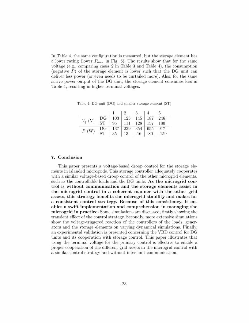
In Table 4, the same configuration is measured, but the storage element hasa lower rating (lower Pmax in Fig. 6). The results show that for the samevoltage (e.g., comparing cases 2 in Table 3 and Table 4), the consumption(negative P ) of the storage element is lower such that the DG unit candeliver less power (or even needs to be curtailed more). Also, for the sameactive power output of the DG unit, the storage element consumes less inTable 4, resulting in higher terminal voltages.
Table 4: DG unit (DG) and smaller storage element (ST)
1 2 3 4 5
Vg (V)DG 103 125 145 187 246ST 95 111 128 157 180
P (W)DG 137 239 354 655 917ST 35 13 -16 -80 -159
7. Conclusion
This paper presents a voltage-based droop control for the storage ele-ments in islanded microgrids. This storage controller adequately cooperateswith a similar voltage-based droop control of the other microgrid elements,such as the controllable loads and the DG units. As the microgrid con-trol is without communication and the storage elements assist inthe microgrid control in a coherent manner with the other gridassets, this strategy benefits the microgrid stability and makes fora consistent control strategy. Because of this consistency, it en-ables a swift implementation and comprehension in managing themicrogrid in practice. Some simulations are discussed, firstly showing thetransient effect of the control strategy. Secondly, more extensive simulationsshow the voltage-triggered reaction of the controllers of the loads, gener-ators and the storage elements on varying dynamical simulations. Finally,an experimental validation is presented concerning the VBD control for DGunits and its cooperation with storage control. This paper illustrates thatusing the terminal voltage for the primary control is effective to enable aproper cooperation of the different grid assets in the microgrid control witha similar control strategy and without inter-unit communication.
23

Acknowledgments
The research was carried out in the frame of the Inter-university Attrac-tion Poles program IAP-VII-02, funded by the Belgian Government. Theresearch of T. Vandoorn and J. D. M. De Kooning is funded by the SpecialResearch Fund (BOF) of Ghent University (Belgium) with a post-doctoraland a PhD fellowship respectively.
References
[1] T. Malakar, S. K. Goswami, A. K. Sinha, Optimum scheduling of amicro grid connected wind-pumped storage hydro plant in a frequencybased pricing environment, Electrical Power and Energy Systems 54(2014) 341–351.
[2] S. Youli, Z. Litifu, K. Nagasaka, Efficiency of micro grid with storagebattery in reliability, economy and environment assessments, ElectricalPower and Energy Systems 3 (2009) 154–162.
[3] Energy storage systems providing primary reserve and peak shaving insmall isolated power systems: An economic assessment, InternationalJournal of Electrical Power & Energy Systems 53 (2013) 675 – 683.
[4] J. K. Kaldellis, D. Zafirakis, E. Kondili, Optimum sizing ofphotovoltaic-energy storage systems for autonomous small islands, In-ternat. Journal of Electrical Power and Energy Systems 32 (2010) 24–36.
[5] A new approach for optimal sizing of battery energy storage system forprimary frequency control of islanded microgrid, Internat. Journal ofElectrical Power and Energy Systems 54 (2014) 325 – 333.
[6] H. Farhangi, The path of the smart grid, IEEE Power & EnergyMagazine 8 (2010) 18–28.
[7] R. H. Lasseter, P. Paigi, Microgrid: A conceptual solution, in: Proc.IEEE Power Electron. Spec. Conf. (PESC 2004), volume 6, Aachen,Germany, pp. 4285–4298.
[8] J. Rocabert, A. Luna, F. Blaabjerg, P. Rodrıgez, Control of powerconverters in AC microgrids, IEEE Trans. Power Electron. 27 (2012)4734–4748.
[9] F. Katiraei, M. R. Iravani, P. W. Lehn, Micro-grid autonomous oper-ation during and subsequent to islanding process, IEEE Trans. PowerDel. 20 (2005) 248–257.
24

[10] M. Gauthier, C. Abbey, F. Katiraei, J.-L. Pepin, M. Plamondon,G. Simard, Planned islanding as a distribution system operator tool forreliability enhancement, in: 19th International Conference on ElectricityDistribution, Vienna.
[11] X. Tan, Q. Li, H. Wang, Advances and trends of energy storage tech-nology in microgrid, Internat. Journal on Electrical Power and EnergySystems 44 (2013) 179 – 191.
[12] T. L. Vandoorn, B. Meersman, L. Degroote, B. Renders, L. Vandevelde,A control strategy for islanded microgrids with dc-link voltage control,IEEE Trans. Power Del. 26 (2011) 703–713.
[13] J. M. Guerrero, M. Chandorkar, T.-L. Lee, P. C. Loh, Advanced con-trol architectures for intelligent microgrids - Part I: Decentralized andhierarchical control, IEEE Trans. Ind. Electron. 60 (2013) 1254–1262.
[14] T. L. Vandoorn, J. D. M. De Kooning, B. Meersman, L. Vandevelde,Review of primary control strategies for islanded microgrids with power-electronic interfaces, Renewable and Sustainable Energy Reviews 19(2013) 613–628.
[15] M. C. Chandorkar, D. M. Divan, R. Adapa, Control of parallel con-nected inverters in standalone ac supply systems, IEEE Trans. Ind.Appl. 29 (1993) 136–143.
[16] M. Marwali, A. Keyhani, Control of distributed generation systems –part i: Voltages and current control, IEEE Trans. Power Electron. 19(2004) 1541–1550.
[17] Y. Mohamed, E. F. El-Saadany, Adaptive decentralized droop con-troller to preserve power sharing stability for paralleled inverters in dis-tributed generation microgrids, IEEE Trans. Power Electron. 23 (2008)2806–2816.
[18] J. M. Guerrero, J. Matas, L. Garcıa de Vicuna, M. Castilla, J. Miret,Decentralized control for parallel operation of distributed generationinverters using resistive output impedance, IEEE Trans. Ind. Electron.54 (2007) 994–1004.
[19] W. Yao, M. Chen, J. M. Guerrero, Z.-M. Qian, Design and analysis ofthe droop control method for parallel inverters considering the impactof the complex impedance on the power sharing, IEEE Trans. Ind.Electron. 58 (2011) 576–588.
25

[20] Y. W. Li, C. N. Kao, An accurate power control strategy for powerelectronics interfaced distributed generation units operating in a lowvoltage multibus microgrid, IEEE Trans. Power Electron. 24 (2009)2977–2988.
[21] A. Engler, O. Osika, M. Barnes, N. Hatziargyriou, DB2 Evaluation ofthe local controller strategies, www.microgrids.eu/micro2000, 2005.
[22] C. Sao, P. Lehn, Control and power management of converter fed mi-crogrids, IEEE Trans. Power Syst. 23 (2008) 1088–1098.
[23] T. L. Vandoorn, J. D. M. De Kooning, B. Meersman, L. Vandevelde,Voltage-based droop control of renewables to avoid on-off oscillationscaused by overvoltages, IEEE Trans. Power Del. 28 (2013) 845–854.
[24] T. L. Vandoorn, B. Renders, L. Degroote, B. Meersman, L. Vandevelde,Active load control in islanded microgrids based on the grid voltage,IEEE Trans. on Smart Grid 2 (2011) 139–151.
26