Control devices HM, HS5 and EO Series 1x and 30
68
RE 92076/2021-04-23, Bosch Rexroth AG Control devices HM, HS5 and EO Series 1x and 30 RE 92076/2021-04-23 Replaces: 05.2018 Features ▶ Electro-hydraulic control with proportional- and control valve ▶ Digital electro-hydraulic control systems with amplifier or on-board electronics and IntraWorks freely programmable operating software (HS5 and HS5E) ▶ Control of swivel angle, pressure and torque limitation (HS5P) ▶ Control for speed variability with HS5 and HS5E. ▶ Mechanical V g min and V g max limitation ▶ Electric control for inside-reservoir installation under fluid (HS5M, EO2M) ▶ The special version enables overcenter and decompression via the pump. ▶ HS5(E)V, HS5(E)L with internal control pressure supply, as standard, including overcenter and decompression ▶ Control and adjustment systems for the axial piston variable pumps A4VSO, A4VBO, A4VSG and A4CSG ▶ Open and closed circuits Contents Type code for A4VSO, A4VBO, A4VSG, A4CSG 2 HM1 / HM2 – Hydraulic, quantity-dependent 6 HM2C – Proportional valve, position transducer 12 HS5(P) – electro-hydraulic control, control valve 16 HS5M – suitable for use under fluid 23 HS5V – Internal control pressure supply, open circuit 27 HS5L – Internal control pressure supply, closed circuit 29 HS5E(P) – Integrated digital electronics (OBE) 32 Electrical data of pilot control valve HS5E 35 Signals and pin assignment of the central connector 37 HS5EV(P) – Integrated digital electronics (OBE) and internal control pressure supply 43 HS5EL - Internal control pressure supply for A4CSG 47 HS5K / EO1K / EO2K – short circuit valve 49 EO1 / EO2 – control with proportional valve 53 EO2M – Suitable for use under fluid 62 Project planning notes 66 Installation instructions 66 Safety instructions 67 Related documentation 68
Transcript of Control devices HM, HS5 and EO Series 1x and 30

RE 92076/2021-04-23, Bosch Rexroth AG
Control devicesHM, HS5 and EO Series 1x and 30
RE 92076/2021-04-23Replaces: 05.2018
Features ▶ Electro-hydraulic control with proportional- and
control valve ▶ Digital electro-hydraulic control systems with amplifier
or on-board electronics and IntraWorks freely programmable operating software (HS5 and HS5E)
▶ Control of swivel angle, pressure and torque limitation (HS5P)
▶ Control for speed variability with HS5 and HS5E. ▶ Mechanical Vg min and Vg max limitation ▶ Electric control for inside-reservoir installation under
fluid (HS5M, EO2M) ▶ The special version enables overcenter and
decompression via the pump. ▶ HS5(E)V, HS5(E)L with internal control pressure supply,
as standard, including overcenter and decompression
▶ Control and adjustment systems for the axial piston variable pumps A4VSO, A4VBO, A4VSG and A4CSG
▶ Open and closed circuits
ContentsType code for A4VSO, A4VBO, A4VSG, A4CSG 2HM1 / HM2 – Hydraulic, quantity-dependent 6HM2C – Proportional valve, position transducer 12HS5(P) – electro-hydraulic control, control valve 16HS5M – suitable for use under fluid 23HS5V – Internal control pressure supply, open circuit 27HS5L – Internal control pressure supply, closed circuit 29HS5E(P) – Integrated digital electronics (OBE) 32Electrical data of pilot control valve HS5E 35Signals and pin assignment of the central connector 37HS5EV(P) – Integrated digital electronics (OBE) and internal control pressure supply 43HS5EL - Internal control pressure supply for A4CSG 47HS5K / EO1K / EO2K – short circuit valve 49EO1 / EO2 – control with proportional valve 53EO2M – Suitable for use under fluid 62Project planning notes 66Installation instructions 66Safety instructions 67Related documentation 68

Bosch Rexroth AG, RE 92076/2021-04-23
2 HM, HS5 and EO Series 1X | Control devicesType code for A4VSO
Type code for A4VSO
01 02 03 04 05 06 07 08 09 10 11 12
A4VS(L) O / –
Hydraulic fluid
01 For details see data sheet 92050
Axial piston unit
02 Swashplate design, variable A4VS(L)1)
Operating mode
03 Pump, open circuit (see data sheet 92050) O
Size (NG)
04 Geometric displacement Vg [cm3] 40 71 125 180 250 355 500 750 1000
Control device 40 71 125 180 250 355 500 750 1000
05 Hydraulic control, depending on quantity
minimum control pressure 20 bar ● ● ● – ● – – – – HM1
minimum control pressure 50/100/125 bar ● ● ● ● ● ● ● ● ● HM2
Customer compact solution: electro-hydraulic control with proportional valve and with AWAX position transducer (prepared for customer-specific control system)
○ ○ ● ○ ● ○ ● ○ ○ HM2C
Digital, electro-hydraulic control, with control valve for electric displacement and pressure and torque limitation with VT-HPC-1-1X with external control pressure supply.For variable-speed drives (Sytronix), please order separate spare SD card, see (data sheet 30237)
● ● ● ● ● ● ● ● ● HS52)
....and with pressure transducer HM20-2X/630-C-K35 ● ● ● ● ● ● ● ● ● HS5P2)
....suitable for use under fluid ● ● ● ● ● ● ● ● ● HS5M2)
....with internal control pressure supply ● ● ● ● ● ● – – – HS5V2)
....and with pressure transducer HM20-2X/630-C-K35 ● ● ● ● ● ● – – – HS5VP2)
Digital electro-hydraulic control system, with control valve with OBE for electric displacement and pressure control and torque limitation with external control pressure supply
● ● ● ● ● ● ● ○ ○ HS5E2)
....and with pressure transducer HM20-2X/630-C-K35 ● ● ● ● ● ● ● ○ ○ HS5EP2)
....with internal control pressure supply ● ● ● ● ● ● – – – HS5EV2)
....and with pressure transducer HM20-2X/630-C-K35 ● ● ● ● ● ● – – – HS5EVP2)
Analog, electro-hydraulic control, with proportional valve for electric displacement control with VT 5035-1X
....minimum control pressure 20 bar ● ● ● – ● – – – – EO12)
....and with short circuit valve ▲ ▲ ▲ – ▲ – – – – EO1K2)
....minimum control pressure 50/100/125 bar ● ● ● ● ● ● ● ● ● EO22)
....suitable for use under fluid ● ● ● ● ● ● ● ● ● EO2M
....and with short circuit valve ▲ ▲ ▲ ▲ ▲ ▲ ▲ ▲ ▲ EO2K2)
Series 40 71 125 180 250 355 500 750 1000
06 Series 1, index 0 ● ● – – – – – – – 10
Series 3, index 0 – – ● ● ● ● ● ● ● 30
Further details on positions 07 to 12 can be found in data sheet 92050
● = Available ○ = On request – = Not available1) Charge pump (L) only available with NG 7502) Operation with HF hydraulic fluids on request

RE 92076/2021-04-23, Bosch Rexroth AG
3 Control devices | HM, HS5 and EO Series 1X Type code for A4VBO
Type code for A4VBO
01 02 03 04 05 06 07 08 09 10 11 12
O / –
Rotary group version
01 For details see data sheet 92122
Axial piston unit 71 125 250 450
02 Swashplate design, variable, high-pressure unit up to 450 bar (see data sheet 92122)
● ● ● ● A4VB
Operating mode
03 Pump, open circuit O
Size (NG)
04 Geometric displacement Vg [cm3] 71 125 250 450
Control device 71 125 250 450
05 Customer compact solution: electro-hydraulic control with proportional valve and with AWAX - position transducer (prepared for customer-specific control system)
○ ○ ○ ○ HM2C
Digital, electro-hydraulic control, with control valve for electric displacement and pressure and torque limitation with VT-HPC-1-1X with external control pressure supply
● ● ● ● HS51)
....and with pressure transducer HM20-2X/630-C-K35 ● ● ● ● HS5P1)
....suitable for use under fluid ● ● ● ● HS5M1)
....with internal control pressure supply ● ● ● – HS5V1)
....and with pressure transducer HM20-2X/630-C-K35 ● ● ● – HS5VP1)
Digital electro-hydraulic control system, with control valve with OBE for electric displacement and pressure control and torque limitation with external control pressure supply
● ● ● ● HS5E1)
....with internal control pressure supply ● ● ● – HS5EV1)
....and with pressure transducer HM20-2X/630-C-K35 ● ● ● – HS5EVP
Series
06 Series 1, index 0 ● – – – 10
Series 3, index 0 – ● ● ● 30
For details see data sheet 92122 (A4VBO)
07 Direction of rotation
08 Sealing material
09 Drive shaft
10 Mounting flange
11 Port plate for working lines
12 Through drive
● = Available ○ = On request – = Not available ▲ = Not for new projects
1) Operation with HF hydraulic fluids on request

Bosch Rexroth AG, RE 92076/2021-04-23
4 HM, HS5 and EO Series 1X | Control devicesType code for A4VSG
Type code for A4VSG
01 02 03 04 05 06 07 08 09 10 11 12 13 14
A4VS G / –
Hydraulic fluid
01 For details see data sheet 92100
Axial piston unit
02 Swashplate design, variable A4VS
Operating mode
03 Pump, closed circuit (see data sheet 92100) G
Size (NG)
04 Geometric displacement Vg [cm3] 40 71 125 180 250 355 500 750 1000
Control device 40 71 125 180 250 355 500 750 1000
05 Hydraulic control, depending on quantity
minimum control pressure 20 bar ● ● ● – ● – – – – HM1
minimum control pressure 50/100/125 bar ● ● ● ● ● ● ● ● ● HM2
Customer compact solution: electro-hydraulic control with proportional valve and with AWAX - position transducer (prepared for customer-specific control system)
○ ○ ● ○ ● ○ ● ○ ○ HM2C
Digital, electro-hydraulic control, with control valve for electric displacement and pressure and torque limitation with VT-HPC-1-1X with external control pressure supply
● ● ● ● ● ● ● ● ● HS51)
....with 2 pressure transducers HM20-2X/630-C-K35 ● ● ● ● ● ● ● ● ● HS5P1)
....with short circuit valve ● ● ● ● ● ● ● ● ● HS5K1)
....with 2 pressure transducers HM20-2X/630-C-K35 ● ● ● ● ● ● ● ● ● HS5KP1)
....suitable for use under fluid ● ● ● ● ● ● ● ● ● HS5M1)
Digital electro-hydraulic control system, with control valve with OBE for electric displacement and pressure control and torque limitation with external control pressure supply
● ● ● ● ● ● ● ● ● HS5E1)
....with 2 pressure transducers HM20-2X/630-C-K35 ● ● ● ● ● ● ● ● ● HS5EP1)
....with short circuit valve ● ● ● ● ● ● ● ● ● HS5EK1)
....with 2 pressure transducers HM20-2X/630-C-K35. ● ● ● ● ● ● ● ● ● HS5EKP1)
Analog electro-hydraulic control, with proportional valve for electric displacement control with VT 5035-1X
....minimum control pressure 20 bar ● ● ● – ● – – – – EO11)
....and with short circuit valve ● ● ● – ● – – – – EO1K1)
....minimum control pressure 50/100/125 bar ● ● ● ● ● ● ● ● ● EO21)
....and with short circuit valve ● ● ● ● ● ● ● ● ● EO2K1)
For details of positions 06 to 14 see data sheet 92100 (A4VSG)
1) Operation with HF hydraulic fluids on request
● = Available ○ = On request – = Not available ▲ = Not for new projects

RE 92076/2021-04-23, Bosch Rexroth AG
5 Control devices | HM, HS5 and EO Series 1X Type code for A4CSG
1) Operation with HF hydraulic fluids on request
Type code for A4CSG
01 02 03 04 05 06 07 08 09 10 11 12 14
A4CS G / –
Axial piston unit
01 Swashplate design, variable A4CS
Operating mode
02 Pump, closed circuit (see data sheet 92105) G
Size (NG)
03 Geometric displacement Vg [cm3] 250 355 500 750
Control device 250 355 500 750
04 Hydraulic control, depending on quantity
Customer compact solution: electro-hydraulic control with proportional valve and with AWAX - position transducer (prepared for customer-specific control system)
● ○ ● ○ HM2C
Digital, electro-hydraulic control, with control valve for electric displacement and pressure and torque limitation with VT-HPC-1-1X with external control pressure supplyFor variable-speed drives (Sytronix), please order the required SD card separately, see (data sheet 30237)
● ● ● ● HS51)
....with 2 pressure transducers HM20-2X/630-C-K35 ● ● ● ● HS5P1)
....with short circuit valve ● ● ● ● HS5K1)
....with 2 pressure transducers HM20-2X/630-C-K35 ● ● ● ● HS5KP1)
....with internal control pressure supply ● ● ● ● HS5L1)
....with 2 pressure transducers HM20-2X/630-C-K35 ● ● ● ● HS5LP1)
Digital electro-hydraulic control system, with control valve with OBE for electric displacement and pressure control and torque limitation with external control pressure supply
● ● ● ● HS5E1)
....with 2 pressure transducers HM20-2X/630-C-K35 ● ● ● ● HS5EP1)
....with internal control pressure supply ● ● ● ● HS5EL1)
....with 2 pressure transducers HM20-2X/630-C-K35 ● ● ● ● HS5ELP1)
....with short circuit valve ● ● ● ● HS5EK1)
....with 2 pressure transducers HM20-2X/630-C-K35 ● ● ● ● HS5EKP1)
Analog electro-hydraulic control, with proportional valve for electric displacement control with VT 5035-1X
....minimum control pressure 100/125 bar ● ● ● ● EO21)
....and with short circuit valve ● ● ▲ ▲ EO2K1)
For details of positions 05 to 14 see data sheet 92105 (A4CSG)
● = Available ○ = On request – = Not available ▲ = Not for new projects

Bosch Rexroth AG, RE 92076/2021-04-23
6 HM, HS5 and EO Series 1X | Control devicesHM1 / HM2 – Hydraulic control, quantity-dependent
HM1 / HM2 – Hydraulic control, quantity-dependent
Type NG 40 71 125 180 250 355 500 750 1000
A4VSO, A4VSG ● ● ● – ● – – – – HM1
A4VSO, A4VSG ● ● ● ● ● ● ● ● ● HM2
The control HM1/2 sets the displacement of the pump depending on the control fluid quantity. This control is used for 2-point circuit or as a base device for controls with proportional valves (additional electric feedback required), e.g. HS5, HS5E, E02, E01.
Spring-centeringThe spring-centering of the stroking cylinder is standard. It is used for setting and adjustment in the depressurized neutral position, but without a defined reset during high-pressure operation.
Notice ▶ The spring feedback in the controller and pump
control spring centering are no safety devices. The controller can stick in an undefined position due to internal contamination (contaminated hydraulic fluid, abrasion or residual contamination from system components). As a result, the flow in the axial piston unit will no longer respond correctly to the operator's specifications. Check whether the application on your machine requires additional safety measures to bring the driven consumer to a safe position (immediate stop).
Swivel angle limitationMinimum and maximum swivel angle limitation is mechanically adjustable up to 50 % Vg max. For size 500, Vg min is adjustable up to 50 % Vg max and Vg max up to 70 % Vg max.
NoticeSetting with A4VSO and A4VBO (open circuit):
▶ The Vg max stop is set to nominal Vg max as standard. Please specify different values in your order
▶ The Vg minstop is set to Vg= 0 l/min with PHD= 20 bar as standard. Other values should be specified when placing the order.
Setting with A4VSG and A4CSG (closed circuit): ▶ The Vg max stops are set on both sides to nominal Vg max.
When ordering, please state other setting requests in plain text.Two versions are available:
Type Control pressure [bar] Sizes
HM1 from 20 40, 71, 125 and 250 (see page 7)
HM2 from 50/100/125 40...1000 (see page 8)
HM2: To minimize the control fluid consumption, the stroking chambers are sealed in sizes 125 to 750.
▼ Flow direction in closed circuit
Direction of rotation
Swiveling range1)
clockwise counter-clockwise
B to A A to B clockwise
A to B B to A counter-clockwise
Overcenter with A4VSO is available on request.
▼ Flow direction in open circuit
Direction of rotation
Swiveling range1)
clockwise counter-clockwise
S to B counter-clockwise
S to B clockwise
1) See swivel angle indicator
15°
15°
0°clockwise
counter-clockwise

RE 92076/2021-04-23, Bosch Rexroth AG
7 Control devices | HM, HS5 and EO Series 1X HM1 / HM2 – Hydraulic control, quantity-dependent
Technical data HM1
Size NG 40 71 125 250
Control pressure (in X1, X2) pmin bar 20 20 20 20
pmax bar 100 100 100 100
Control stroke smax mm 14.2 17.1 20.7 25.9
Control area A cm2 16.6 24.6 36.3 56.7
Control volume VS max cm3 23.6 42.1 75.2 147
Weight: approx. (A4VSO…HM1…N00) m kg 38 55 92 194
Circuit diagrams HM1
▼ Sizes 40 and 71 Example: open circuit A4VSO
▼ Sizes 125 and 250 Example: closed circuit A4VSG
B1 MBBX1X2
K1 K2 R(L)TMSU S
MB MA
B
X1 X2K2K3 R(L)TU
A
E
Ports with swivel direction
X1 Control pressure counter-clockwise
X2 Control pressure clockwise

Bosch Rexroth AG, RE 92076/2021-04-23
8 HM, HS5 and EO Series 1X | Control devicesHM1 / HM2 – Hydraulic control, quantity-dependent
Technical data HM2For A4CSG with HM2, the control pressure relief valve (see data sheet 92105, circuit diagram for version F with integrated boost pump) is not required and is replaced with a threaded plug.
To minimize the control fluid consumption, the stroking chambers are sealed in sizes 125...1000 and can be bled via the ports R2…R7.
Size NG 40 71 125 180 250 355 500 750 1000
Control pressure (in X1, X2) pmin bar 50 50 50 100 100 100 125 125 125
pmax bar 350 350 350 350 350 350 350 350 350
Control stroke smax mm 14.2 17.1 20.7 20.7 25.9 25.9 32.6 37.0 41.4
Control area A cm2 8.1 12.6 18.1 18.1 28.3 28.3 38.2 56.8 63.6
Control volume VS max cm3 11.4 21.5 37.5 37.5 73.2 73.2 124.5 210 263.3
Weight: approx. (A4VSO…HM2…N00) m kg 38 55 92 106 194 214 327 470 600
Circuit diagrams HM2
▼ Sizes 40 and 71 Example: open circuit A4VSO
▼ Sizes 125 to 355 Example: open circuit A4VSO
B1 MBBX1X2
K1 K2 R(L)TMSU S
B1 MBB
X1 X2K1 K2 R(L)TMSU S R5 R6R7 R2R3R4
▼ Sizes 500 to 1000 Example: closed circuit A4VSG
X1 X2
MX2MX1
MX
U
MB MA
B A
E
R5 R6 R7 R2R3R4R(L)TK2K3
Ports
X1 Control pressure
X2 Control pressure
MX, MX1, MX2 Measuring ports control pressure
R2 … R7 Air bleeding the stroking chamber

RE 92076/2021-04-23, Bosch Rexroth AG
9 Control devices | HM, HS5 and EO Series 1X HM1 / HM2 – Hydraulic control, quantity-dependentDimensions [mm]
Dimensions HM1/HM2
▼ A4VSO and A4VSG, size 40 and 71
Mounting face in accordance with porting pattern DIN 24340 A6
B
R(L)
R(L)
X1
X2
RL
U
A 3
A 1
A 4
A5
A 2
T
15°0
°15°
NG A1 A2 A3 A4 A5
40 296 136 24 102 217 For detailed dimensions and technical data for the variable pump, see data sheet 92050 (A4VSO) or 92100 (A4VSG)71 332 157 28 120 245
Ports Standard Size pmax [bar]1) State2)
X1, X2 Control pressure DIN 3852-1 M14 × 1.5; 12 deep 100 (with HM1)350 (with HM2)
O
1) Depending on the application, momentary pressure peaks can occur. Keep this in mind when selecting measuring devices and fittings.
2) O = Must be connected (plugged on delivery) X = Plugged (in normal operation)

Bosch Rexroth AG, RE 92076/2021-04-23
10 HM, HS5 and EO Series 1X | Control devicesHM1 / HM2 – Hydraulic control, quantity-dependent
Dimensions [mm]
Dimensions HM1/HM2
▼ A4VSO, A4VSG and A4CSG, sizes 125 to 355
B
R(L)
R(L)
X1
X2
U
A 3
A 3
A 1
A 4
A5
A 2
T
RL
S
R5
R6
R2
R3
R7/R4
15°0
°15°
NG A1 A2 A3 A4 A5
125/1802) 402 191 67 186.5 251 For detailed dimensions and technical data for the variable pump, see data sheet 92050 (A4VSO), 92100 (A4VSG) or 92105 (A4CSG)250/3552) 485 238 71 233 311
Ports Standard Size pmax [bar]1) State3)
X1, X2 Control pressure DIN 3852-1 M14 x 1.5; 12 deep (NG 125 and 180)M18 × 1.5; 12 deep (NG 250 and 355)
100 (with HM1)350 (with HM2)
OO
R2 … R7 Air bleeding the stroking chamber DIN 3852-1 M10 × 1; 8 deep 350 (only with HM2) X
1) Depending on the application, momentary pressure peaks can occur. Keep this in mind when selecting measuring devices and fittings.
2) Size 180 and 355 only with HM2
3) O = Must be connected (plugged on delivery) X = Plugged (in normal operation)

RE 92076/2021-04-23, Bosch Rexroth AG
11 Control devices | HM, HS5 and EO Series 1X HM1 / HM2 – Hydraulic control, quantity-dependentDimensions [mm]
Dimensions HM2
▼ A4VSO, A4VSG and A4CSG, sizes 500 to 1000
Mounting face in accordance with porting pattern DIN 24340 A6
X1
MX1
MX1
MX
MX2 X2
X1, X2
A 3
A 1
A 4
A5
A 2
RL
R2
R3
R6
R5
R7/R4
R(L)
B
T S
U
15°0
°15°
NG A1 A2 A3 A4 A5
500 555 283 50 274 388For detailed dimensions and technical data for the variable pump, see data sheet 92050 (A4VSO), 92100 (A4VSG) or 92105 (A4CSG)
750 630 320 50 304 420
1000 670 347 50 327 486
Ports Standard Size1) pmax [bar]2) State
X1, X2 Control pressure DIN 3852-1 M27 × 2; 16 deep 350 O
MX, MX1, MX2 Control pressure measuring DIN 3852-1 M14 × 1.5; 12 deep 350 X
R2 … R7 Air bleeding the stroking chamber DIN 3852-1 M14 × 1.5; 12 deep 350 X
1) Depending on the application, momentary pressure peaks can occur. Keep this in mind when selecting measuring devices and fittings.
2) O = Must be connected (plugged on delivery) X = Plugged (in normal operation)

Bosch Rexroth AG, RE 92076/2021-04-23
12 HM, HS5 and EO Series 1X | Control devicesHM2C – Customer solution with proportional valve, position transducer
HM2C – Customer solution with proportional valve, position transducer
Type NG 40 71 125 180 250 355 450 500 750 1000
A4VSO ○ ○ ● ○ ● ○ – ● ○ ○
A4VBO – ○ ○ – ○ – ○ – – –
A4VSG ○ ○ ● ○ ● ○ – ● ○ ○
A4CSG – – – – ● ○ – ● ○ –
The HM2C customer solution provides the base unit, sensors and actuators required for a control system. This means that a pump control system can be built up by the end users themselves for electronic volume, pressure and power control. Notice: No finished pump control electronics is available for the HM2C like for the HS5. The HM2C can be integrated freely in the control architecture of the plant operator machine with defined standard interfaces. On the pump side, the base unit is equipped with:
▶ a proportional valve (including integrated valve amplifier) ▶ Swivel angle sensor
All components are already installed and piped up and only have to be connected with the on-site control.The HM2C control receives the setpoint value for the mounted proportional valve from the superordinate control in the form of an electric current signal.Component Designation Material number
Valve Sizes 40 to 1804WREE6V08-2X/G24K31/F1V-989Data sheet 29061
R901438013
Sizes 250 to 10004WREE6V16-2X/G24K31/F1V-989Data sheet 29061
R901377315
Swivel angle sensor
Standardized output signal4 to 20 mA and 2 to 10 V
Depending on the size
The pump setting is recorded via the swivel angle sensor. These two parameters are therefore available to the superordinate control. Example applications:
▶ The plant operator wants to retain his own machine control and integrate the pump control in it.
This type of customer-specific solution can be set up with the HM2C and the Motion Logic Control (MLC) from Bosch Rexroth, for example. Together with a matching I/O axis module, a freely programmable control is available to the user.The axis module and the MLC for actuating the HM2C control are not included in the HM2C scope of delivery.
Spring-centering The spring-centering of the stroking cylinder is standard.It is used for setting and adjustment in the depressurized neutral position, but without a defined reset during high-pressure operation.
Notice ▶ The spring feedback in the controller and pump
control spring centering are no safety devices. The controller can stick in an undefined position due to internal contamination (contaminated hydraulic fluid, abrasion or residual contamination from system components). As a result, the flow in the axial piston unit will no longer respond correctly to the operator's specifications. Check whether the application on your machine requires additional safety measures to bring the driven consumer to a safe position (immediate stop).
To minimize the control fluid consumption, the stroking chambers are sealed in sizes 125 to 1000 and can be bled via the ports R2 to R7.Swivel angle limitationMinimum and maximum swivel angle limitation is mechanically adjustable up to 50 % Vg max. For size 500, Vg min is adjustable up to 50 % Vg max and Vg max up to 70 % Vg max (75 % with A4VBO 450).
NoticeSetting with A4VSO (open circuit):
▶ The Vg max stop is set to nominal Vg max as standard. Please specify different values in your order
▶ The Vg minstop is set to Vg= 0 l/min with PHD= 20 bar as standard. Other values should be specified when placing the order.
When ordering, please state other setting requests in plain text.
RE 92076/2021-04-23, Bosch Rexroth AG
13 Control devices | HM, HS5 and EO Series 1X HM2C – Customer solution with proportional valve, position transducer
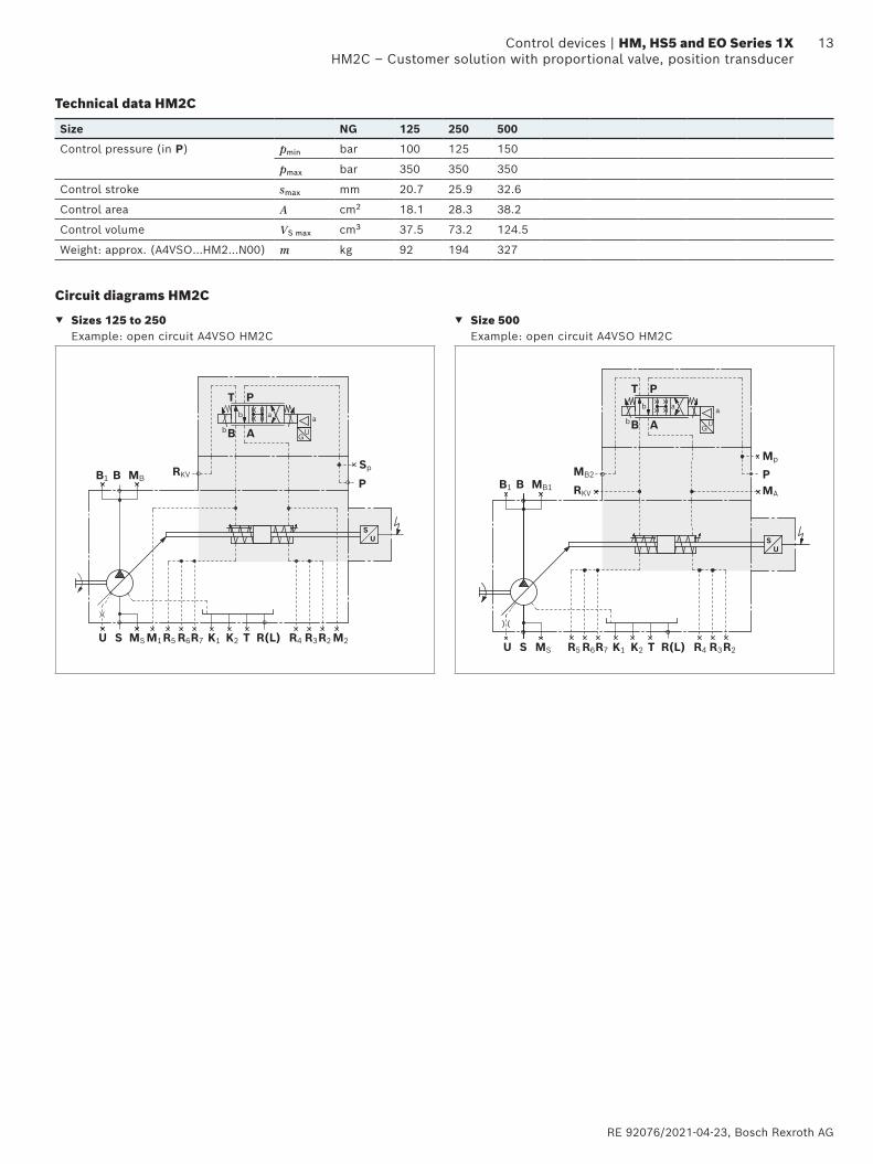
Technical data HM2C
Size NG 125 250 500
Control pressure (in P) pmin bar 100 125 150
pmax bar 350 350 350
Control stroke smax mm 20.7 25.9 32.6
Control area A cm2 18.1 28.3 38.2
Control volume VS max cm3 37.5 73.2 124.5
Weight: approx. (A4VSO…HM2…N00) m kg 92 194 327
Circuit diagrams HM2C
▼ Sizes 125 to 250 Example: open circuit A4VSO HM2C
▼ Size 500 Example: open circuit A4VSO HM2C
US
b a
ba
GU
T P
AB
RKVSp
PB1 MBB
K1 K2 R(L)TMS M1 M2U S R5 R6R7 R2R3R4
US
b a
ba
GU
T P
AB
B1 MB1
MB2
RKV
Mp
MA
PB
K1 K2 R(L)TMSU S R5 R6R7 R2R3R4

Bosch Rexroth AG, RE 92076/2021-04-23
14 HM, HS5 and EO Series 1X | Control devicesHM2C – Customer solution with proportional valve, position transducer
Dimensions [mm]
Dimensions HM2C
▼ A4VSO, A4VSG and A4CSG, size 125, 250
A 2
A3
A 1
A4
RL 15
°0°1
5°
R(L)
B
R7/R4
SP
PRKV
M2
M1
R2
R3
R5
R6
U
NG A1 A2 A3 A4
125 401 304 350 309 For detailed dimensions and technical data for the variable pump, see data sheet 92050 (A4VSO), 92100 (A4VSG) or 92105 (A4CSG)250 485 344 412 372
Ports Standard Size pmax [bar]1) State2)
P, RKV Control pressure DIN 3852-1 M27 × 2 100 O
MX, MX1, MX2 Control pressure measuring DIN 3852-1 M14 × 1.5 315 X
R2 … R7 Air bleeding the stroking chamber DIN 3852-1 M14 × 1.5 315 X
1) Depending on the application, momentary pressure peaks can occur. Keep this in mind when selecting measuring devices and fittings.
2) O = Must be connected (plugged on delivery) X = Plugged (in normal operation)

RE 92076/2021-04-23, Bosch Rexroth AG
15 Control devices | HM, HS5 and EO Series 1X HM2C – Customer solution with proportional valve, position transducerDimensions [mm]
Dimensions HM2C
▼ A4VSO, A4VSG and A4CSG, size 500
A 4
A 2
A3
A 1
A 6
A5
A7
RL 15
°0°1
5°
R(L)MP
B
R7/R4
R2
R3
PRKV
RKVMA
MB2
P
MB2
R5
R6
NG A1 A2 A3 A4 A5 A6 A7
500 555 363 520 274 388 50 392 For detailed dimensions and technical data for the variable pump, see data sheet 92050 (A4VSO), 92100 (A4VSG) or 92105 (A4CSG)
Ports Standard Size pmax [bar]1) State2)
P, RKV Control pressure DIN 3852-1 M27 × 2 100 O
MX, MX1, MX2 Control pressure measuring DIN 3852-1 M14 × 1.5 315 X
R2 … R7 Air bleeding the stroking chamber DIN 3852-1 M14 × 1.5 315 X
1) Depending on the application, momentary pressure peaks can occur. Keep this in mind when selecting measuring devices and fittings.
2) O = Must be connected (plugged on delivery) X = Plugged (in normal operation)

Bosch Rexroth AG, RE 92076/2021-04-23
16 HM, HS5 and EO Series 1X | Control devicesHS5(P) – electro-hydraulic control with control valve
Dimensions [mm]
HS5(P) – electro-hydraulic control with control valve
Type NG 40 71 125 180 250 355 450 500 750 1000
A4VSO, A4VSG ● ● ● ● ● ● – ● ● ●
HS5(P)A4CSG – – – – ● ● – ● ● –
A4VBO – ● ● – ● – ● – – –
For electric displacement and pressure control as well as torque limitation with VT-HPC-1-1X with external control pressure supplyThe control HS5 sets the displacement of the pump with the mounted direct operated control valve proportional to the setpoint value.The pump setting is reported by an inductive position transducer.With HS5P, the mounted pressure transducer HM20 (see data sheet 30272) records the system pressure, with A4VSG and A4CSG, each pressure side is assigned a pressure transducer. Together with the relevant control electronics VT-HPC-1-1X and the operating software IndraWorks, the user has a precise and freely parameterizable control, which offers a comfortable operating and diagnosis interface.The digital control amplifier VT-HPC-1-1X for actuating the HS5 control is not included in the scope of delivery, please order separately in accordance with data sheet 30237.The programming of the digital control electronics takes place via the Ethernet interface of the IndraWorks operating software.Machine and system dynamics must be optimized by the system operator using the pressure control function.Spring-centering The spring-centering of the stroking cylinder is standard. It is used for setting and adjustment in the depressurized neutral position, but without a defined reset during high-pressure operation.
Notice ▶ The spring feedback in the controller and pump control
spring centering are no safety devices. The controller can stick in an undefined position due to internal contamination (contaminated hydraulic fluid, abrasion or residual contamination from system components). As a result, the flow in the axial piston unit will no longer respond correctly to the operator's specifications. Check whether the application on your machine requires additional safety measures to bring the driven consumer to a safe position (immediate stop).
To minimize the control fluid consumption, the stroking chambers are sealed in sizes 125...1000 and can be bled via the ports R2 … R7.Swivel angle limitationMinimum and maximum swivel angle limitation is mechanically adjustable up to 50 % Vg max. For size 500, Vg min is adjustable up to 50 % Vg max and Vg max up to 70 % Vg max (75 % with A4VBO 450).
NoticeSetting with A4VSO (open circuit):
▶ The Vg max stop is set to nominal Vg max as standard. Please specify different values in your order
▶ The Vg min stop is set to nominal Vg= 0 l/min with PHD= 20 bar as standard. Other values should be specified when placing the order.
Setting with A4VSG and A4CSG (closed circuit): ▶ The Vg max stops are set on both sides to nominal
Vg max.
When ordering, please state other setting requests in plain text.
Optional: ▶ HS5P with one (open circuit) or two (closed circuit)
pressure transducer(s) for pressure control and torque limitation
▶ Speed variation possible with SD card: VT-SD-HPC-HS5n. For a description of the functionality, see pump control 30237-Z manual.

RE 92076/2021-04-23, Bosch Rexroth AG
17 Control devices | HM, HS5 and EO Series 1X HS5(P) – electro-hydraulic control with control valve
Technical data HS5(P)
Size NG 40 71 125 180 250 355 450 500 750 1000
Control pressure (in P)
A4VSO, A4VSG, A4CSG
pmin bar 100 100 100 125 125 125 – 150 150 150
A4VBO pmin bar – 130 130 – – – 190 – – –
pmax1) bar 350 350 350 350 350 350 350 350 350 350
Control stroke smax mm 14.2 17.1 20.7 20.7 25.9 25.9 32.6 32.6 37.0 41.4
Control area A cm2 8.1 12.6 18.1 18.1 28.3 28.3 38.2 38.2 56.8 63.6
Control volume VS max cm3 11.4 21.5 37.5 37.5 73.2 73.2 124.5 124.5 210 263.3
Actuating time tmin2) s 0.04 0.06 0.09 0.09 0.12 0.12 0.15 0.15 0.2 0.25
Weight: approx. (A4VSO…HS5…N00)
m kg 42 59 98 112 200 220 333 333 476 606
Control loop performance hysteresis ≤ 0.2%
Repeat accuracy ≤ 0.2%
Linearity deviation swivel angle ≤ 1.0%
Linearity deviation pressure ≤ 1.5% of pmax3)
A4VSO – open circuit
▼ Characteristic curve
p
α
Basic setting for design without short circuit valve, de-energized proportional valve and connected control pressure: Vg min (see table).
▼ Flow direction S to B
Direction of rotation
Swiveling range4) Basic setting
clockwise counter-clockwise Vg min (counter-clockwise)
counter-clockwise clockwise Vg min (clockwise)
A4VSG and A4CSG – closed circuit
▼ Characteristic curve
p
+α
p
-α
Basic setting for design without short circuit valve, de-energized proportional valve and connected control pressure: Vg max (see table).
▼ Flow direction
Direction of rotation
Swiveling range4) Flow direction
Basic setting
clockwiseclockwise B to A Vg max clockwise
counter-clockwise A to B
counter-clockwise
clockwise A to B Vg max counter-clockwisecounter-clockwise B to A
1) Due to the permissible data of the proportional valve2) With minimum control pressure3) Pressure transducer value
4) See swivel angle indicator
15°
15°
0°clockwise
counter-clockwise

Bosch Rexroth AG, RE 92076/2021-04-23
18 HM, HS5 and EO Series 1X | Control devicesHS5(P) – electro-hydraulic control with control valve
Circuit diagrams HS5(P)
▼ Sizes 40 and 71 Example: A4VSO HS5P (with pressure transducer)
Clockwise rotation Counter-clockwise rotation
U S MS R(L)TK1 K2
B MBB1 RKV(5)
1
3
2
4SP
P
US
PI
b b a a
PT
AB
b b a
PT
AB
U S MS R(L)TK1 K2
B(5) MBB1RKV
1
3
2
4SP
P
US
PI
a
▼ Sizes 125 to 355 Example: A4VSO HS5P (with pressure transducer)
Clockwise rotation Counter-clockwise rotation
U S R5MSM1 M2R6 R7 R2R3R4R(L)TK1K2
B(5) MBB1 RKV
3
2
4SP
P
1
US
PI
b b a
PT
AB
a
B
U S R5MSM1 M2R6 R7 R2R3R4R(L)TK1K2
1
3
2
(5)
4SP
PMBB1RKV
US
PI
b b a
PT
AB
a
1 Pump with hydraulic control device A4VSO (see data sheet 92050), A4VBO (see data sheet 92122) or A4VHO (data sheet in preparation)
2 4/4 directional control valve (see data sheet 29027)
NG Type
40 to 180 4WRPH6CA24L-2X/G24Z4/V-855
250 and 355 4WRPH6CA40L-2X/G24Z4/V-855
3 Inductive position transducer
NG Type
40, 125 and 180 AWAX004D03
71 AWAX004D02 with spacer
250, 355 AWAX004D02
with round connector 4-pin M12 × 14 Intermediate plate5 Only with HS5P: Pressure transducer HM20-2X/630-C-K35
(see data sheet 30272) with intermediate flange, with A4VSG and A4CSG, each pressure side has 1 pressure transducer assigned and mounted

RE 92076/2021-04-23, Bosch Rexroth AG
19 Control devices | HM, HS5 and EO Series 1X HS5(P) – electro-hydraulic control with control valve
▼ Sizes 500 to 1000 Example: A4VSG HS5P (with pressure transducer)
B A
E
U R5 R6 R7 R2R3R4R(L)TK3 K2
(5)
P
MB1 MA1
MA2
MP
MB2
RKV
1
3
2
4
US
PI
PI
b b a
PT
AB
a
1 Pump with hydraulic control device A4VSG (see data sheet 92100)2 4/4 directional control valve (see data sheet 29027)
NG Type
500 to 1000 4WRPH6CA40L-2X/G24Z4/V-855
3 Inductive position transducer
NG Type
500 to 1000 AWAX004D02
with round connector 4-pin M12 × 14 Intermediate plate5 Only with HS5P: Pressure transducer HM20-2X/630-C-K35
(see data sheet 30272) with intermediate flange, with A4VSG and A4CSG, each pressure side has 1 pressure transducer assigned and mounted
Ports
P Control pressure
SP Control pressure accumulator
RKV Control fluid return flow
M… Measuring ports control pressure
R2 … R7 Air bleeding the stroking chamber

Bosch Rexroth AG, RE 92076/2021-04-23
20 HM, HS5 and EO Series 1X | Control devicesHS5(P) – electro-hydraulic control with control valve
Dimensions [mm]
Dimensions HS5(P)
▼ Size 40 and 71; example: A4VSO HS5P with pressure transducer in B (clockwise rotation with; counter-clockwise without HM20)
With A4VSO and A4VBO counter-clockwise and clockwise rotation, partly different components and dimensions. With A4VSG, the dimensions "L" apply for both directions of rotation.
B
B
Einschraubloch M33
A 5 A 8
A 9 A 1
0 A 6
A 1
0L
A 6L
SP
SP
RKV
RKV
P
P
R(L)
LR
15°0
°15°
(5)
A 2A 2
L
A 3
A7A4
A 1
30
23
1
4
RKV
W
A 5L
A 8L
A 3L
A7LA4L
23
1
4
RKV
A9L
to mounting face to mounting face
to mounting face to mounting face
Transport lock▼ Detail W clockwise rotation
▼ Clockwise rotation ▼ Counter-clockwise
rotation
▼ Detail W counter-clockwise rotation
With pressure transducer, position 5: Intermediate flange with through
holes (dimensions dependent on NG) for mounting bolts (for fastening
threads, see relevant pump data sheet)
Valve mounting withA4VSGA4VSO for clockwise rotationA4VBO for clockwise rotation
Valve mounting withA4VSO for counter-clockwise rotationA4VBO for counter-clockwise rotation
NG A1 A2 A2L A3 A3L A4 A4L A5 A5L A6(L) A7 A7L A8 A8L A9 A9L A10(L)
40 296 110.3 104 251 232 222 229.5 108 107 48 273 253 128 94 30 0 48
71 332 105.3 107.1 268 249 249 256.5 123 122 48.4 300 280 143 109 30 0 49.6
For detailed dimensions and technical data for the variable pump, see data sheets 92050 (A4VSO), 92122(A4VBO) or 92100 (A4VSG)
Ports Standard1) Size pmax [bar]2) State3)
P Control pressure DIN 3852-1 M22 × 1.5; 14 deep 315 O
SP Control pressure accumulator DIN 3852-1 M22 × 1.5; 14 deep 315 X
RKV Control fluid return flow DIN 3852-1 M22 × 1.5; 14 deep 210 O
1) ISO 6149 with A4VBO 712) Depending on the application, momentary pressure peaks can
occur. Keep this in mind when selecting measuring devices and fittings.
3) O = Must be connected (plugged on delivery) X = Plugged (in normal operation)
For key, see page 19
RE 92076/2021-04-23, Bosch Rexroth AG
21 Control devices | HM, HS5 and EO Series 1X HS5(P) – electro-hydraulic control with control valveDimensions [mm]
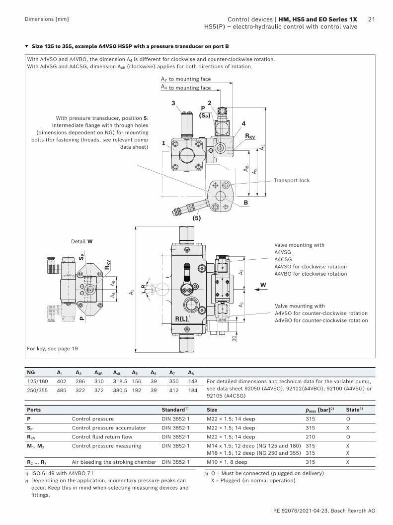
▼ Size 125 to 355, example A4VSO HS5P with a pressure transducer on port B
With A4VSO and A4VBO, the dimension A4 is different for clockwise and counter-clockwise rotation. With A4VSG and A4CSG, dimension A4R (clockwise) applies for both directions of rotation.
Detail W30
B
M12 (x1.75)
Einschraubloch M33
A 2A 2
A 6
A 6 A 1
S P
RK
V
P R(L)
LR
15°0
°15°
W
A 5A 8
A 3
A7A4
23
1
P(SP)
4
RKV
(5)
to mounting face
to mounting face
Transport lock
With pressure transducer, position 5: Intermediate flange with through holes
(dimensions dependent on NG) for mounting bolts (for fastening threads, see relevant pump
data sheet)
Valve mounting withA4VSGA4CSGA4VSO for clockwise rotationA4VBO for clockwise rotation
Valve mounting withA4VSO for counter-clockwise rotationA4VBO for counter-clockwise rotation
NG A1 A3 A4R A4L A5 A6 A7 A8
125/180 402 286 310 318.5 156 39 350 148 For detailed dimensions and technical data for the variable pump, see data sheet 92050 (A4VSO), 92122(A4VBO), 92100 (A4VSG) or 92105 (A4CSG)
250/355 485 322 372 380.5 192 39 412 184
Ports Standard1) Size pmax [bar]2) State3)
P Control pressure DIN 3852-1 M22 × 1.5; 14 deep 315 O
SP Control pressure accumulator DIN 3852-1 M22 × 1.5; 14 deep 315 X
RKV Control fluid return flow DIN 3852-1 M22 × 1.5; 14 deep 210 O
M1, M2 Control pressure measuring DIN 3852-1 M14 x 1.5; 12 deep (NG 125 and 180)M18 × 1.5; 12 deep (NG 250 and 355)
315315
XX
R2 … R7 Air bleeding the stroking chamber DIN 3852-1 M10 × 1; 8 deep 315 X
For key, see page 19
1) ISO 6149 with A4VBO 712) Depending on the application, momentary pressure peaks can
occur. Keep this in mind when selecting measuring devices and fittings.
3) O = Must be connected (plugged on delivery) X = Plugged (in normal operation)

Bosch Rexroth AG, RE 92076/2021-04-23
22 HM, HS5 and EO Series 1X | Control devicesHS5(P) – electro-hydraulic control with control valve
Dimensions [mm]
▼ A4VSO, A4VBO, A4VSG and A4CSG, size 500 to 1000 Example A4VSG HS5P with two pressure transducers on port B
LR
15
15
0
R3 R2
R(L)
A 1
A3
A5
R5R6
30
A 6
RKV
P
MA
A 4A 2
R7/R4
43
1
2
MB2MP
M14 (x2)
B
A
(5)
to mounting face
to mounting face
with counter-clockwise rotation A3 = A5
Transport lock
With pressure transducer, position 5: Intermediate flange with through
holes (dimensions dependent on NG) for mounting bolts (for fastening
threads, see relevant pump data sheet)
Valve mounting withA4VSGA4CSGA4VSO for clockwise rotationA4VBO for clockwise rotation
Valve mounting withA4VSO for counter-clockwise rotationA4VBO for counter-clockwise rotation
NG A1 A2 A3 A4 A5 A6
500(450 with A4VBO)
555 363 392 274 388 50 For detailed dimensions and technical data for the variable pump, see data sheet 92050 (A4VSO), 92122 (A4VBO), 92100 (A4VSG) or 92105 (A4CSG)750 630 402 424 304 420 50
1000 670 429 490 327 486 50
Ports Standard1) Size pmax [bar]2) State3)
P Control pressure DIN 3852-1 M27 × 2; 16 deep 315 O
RKV Control fluid return flow DIN 3852-1 M27 × 2; 16 deep 120 O
MA2, MB2, MP Control pressure measuring DIN 3852-1 M14 × 1.5; 12 deep 315 X
R2 … R7 Air bleeding the stroking chamber DIN 3852-1 M14 × 1.5; 12 deep 315 X
For key, see page 19
1) ISO 6149 with A4VBO 712) Depending on the application, momentary pressure peaks can
occur. Keep this in mind when selecting measuring devices and fittings.
3) O = Must be connected (plugged on delivery) X = Plugged (in normal operation)

RE 92076/2021-04-23, Bosch Rexroth AG
23 Control devices | HM, HS5 and EO Series 1X HS5M – suitable for use under fluid
HS5M – suitable for use under fluid
Type NG 40 71 125 180 250 355 450 500 750 1000
A4VSO, A4VSG ● ● ● ● ● ● – ● ● ●HS5M
A4VBO – ● ● – ● – ● – – –
The version HS5M corresponds to the HS5 design, but without proportional valve, but with pilot pressure ports X1 and X2.The proportional valve can be positioned separately in the system and piped up via the designated ports X1 and X2 of the pump.The unit can be installed in the reservoir together with the directly mounted position transducer. Approved for HLP fluids DIN 51524.Recommendation
▶ Directional control valve 4WRPH6, see data sheet 29027 ▶ Electronics VT-HPC-1-1X see data sheet 30237 ▶ For cables, see data sheet 30237-B
NoticeSetting with A4VSO (open circuit):
▶ The Vg max stop is set to nominal Vg max as standard. Please specify different values in your order
▶ The Vg min stop is set to nominal Vg= 0 l/min with PHD= 20 bar as standard. Other values should be specified when placing the order.
Setting with A4VSG and A4CSG (closed circuit): ▶ The Vg max stops are set on both sides to
nominal Vg max.
▼ Flow direction in closed circuit
Direction of rotation Swiveling range1)
clockwise counter-clockwise
B to A A to B clockwise
A to B B to A counter-clockwise
▼ Flow direction in open circuit
Direction of rotation Swiveling range1)
clockwise counter-clockwise
S to B counter-clockwise
S to B clockwise
Technical data inductive position transducer AWAX
Temperature range -25 °C to +80 °Cfor AWAX004D02 and AWAX004D03
Type of protection IPX7 DIN VDE 0470-EN 60529
Typical temperature drift 0.05% / K (based on the total output voltage swing)
Vibration resistance 10 g sine; 10 g noise; 15 g shock
Use under fluid approved for HLPD 46(with installed mating connector)
Sealing material FKM
Technical data HS5M
Size NG 40 71 125 180 250 355 500 750 1000
Control pressure (in X1, X2) pmin bar 50 50 50 100 100 100 125 125 125
pmax2) bar 350 350 350 350 350 350 350 350 350
Control stroke from 0 cm3 to Vg max smax mm 14.2 17.1 20.7 20.7 25.9 25.9 32.6 37.0 41.4
Control area A cm2 8.1 12.6 18.1 18.1 28.3 28.3 38.2 56.8 63.6
Control volume VS max cm3 11.4 21.5 37.5 37.5 73.2 73.2 124.5 210 263.3
Weight: approx. (A4VSO…HS5M…N00) m kg 38 55 92 106 194 214 327 470 600
1) See swivel angle indicator
15°
15°
0°clockwise
counter-clockwise
2) Observe any restrictions due to the proportional valve

Bosch Rexroth AG, RE 92076/2021-04-23
24 HM, HS5 and EO Series 1X | Control devicesHS5M – suitable for use under fluid
Circuit diagrams HS5M
▼ Size 40 to 1000 for A4VSO and A4VSG, size 250 to 750 for A4CSG Example: A4VSO…HS5M, size 125 to 1000
Clockwise rotation Counter-clockwise rotation
U S MS R(L)TK1R7 R4 R3 R2R6R5 K2
B MBB1
X1 X2
1
2
3
US
b b a
PT
AB
a
U S MS R(L)TK1R7 R4 R3 R2R6R5 K2
B MBB1
X1 X2
1
2
3
US
b b a
PT
AB
a
1 Pump with hydraulic control device A4VSO (see data sheet 92050)
2 Inductive position transducer:
NG Type
40, 125 and 180 AWAX004D03
71 AWAX004D02 with spacer
250 to 1000 AWAX004D02
with round connector 4-pin M12 × 13 Port plate
Ports
X1 Control pressure
X2 Control pressure
R2 … R7 Air bleeding of stroking chamber (NG 125 to 1000)
RE 92076/2021-04-23, Bosch Rexroth AG
25 Control devices | HM, HS5 and EO Series 1X HS5M – suitable for use under fluidDimensions [mm]
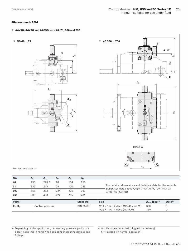
Dimensions HS5M
▼ A4VSO, A4VSG and A4CSG, size 40, 71, 500 and 750
RL 15
°0°1
5°
15°0
°15°
B
W
A 4A 2
A 4A 2
3
3
X1 X2A3
A 1
A5
A 1
A 3
A5
X1
X2
Detail W
▼ NG 40 … 71 ▼ NG 500 … 750
NG A1 A2 A3 A4 A5
40 296 223.7 28 104 218For detailed dimensions and technical data for the variable pump, see data sheet 92050 (A4VSO), 92100 (A4VSG) or 92105 (A4CSG)
71 332 243 28 120 245
500 555 363 224 205 399
750 630 400 224 235 431
Ports Standard Size pmax [bar]1) State2)
X1, X2 Control pressure DIN 3852-1 M14 × 1.5; 12 deep (NG 40 and 71)M22 × 1.5; 14 deep (NG 500)
350350
OO
1) Depending on the application, momentary pressure peaks can occur. Keep this in mind when selecting measuring devices and fittings.
2) O = Must be connected (plugged on delivery) X = Plugged (in normal operation)
For key, see page 24

Bosch Rexroth AG, RE 92076/2021-04-23
26 HM, HS5 and EO Series 1X | Control devicesHS5M – suitable for use under fluid
Dimensions [mm]
▼ A4VSO, A4VSG and A4CSG, sizes 125 to 355
RL 15
°0°1
5°
B
X1
X2
1
2
3
R(L)
A 3
A 3
A 1
A 4
A5
A 2
NG A1 A2 A3 A4 A5
125/180 402 272 67 186.5 251 For detailed dimensions and technical data for the variable pump, see data sheet 92050 (A4VSO), 92100 (A4VSG) or 92105 (A4CSG)250/355 485 318.2 71 233 310.5
Ports Standard Size pmax [bar]1) State2)
X1, X2 Control pressure DIN 3852-1 M14 x 1.5; 12 deep (NG 125 and 180)M18 × 1.5; 12 deep (NG 250 and 355)
350350
OO
1) Depending on the application, momentary pressure peaks can occur. Keep this in mind when selecting measuring devices and fittings.
2) O = Must be connected (plugged on delivery) X = Plugged (in normal operation)
For key, see page 24
RE 92076/2021-04-23, Bosch Rexroth AG
27 Control devices | HM, HS5 and EO Series 1X HS5V – control with internal control pressure supply for open circuit
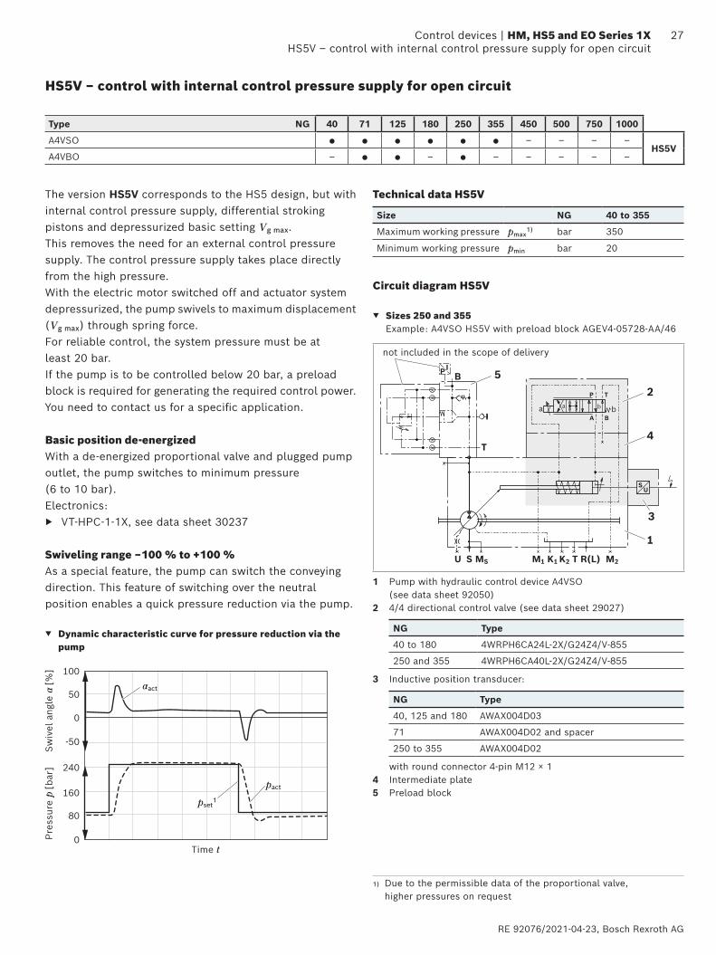
HS5V – control with internal control pressure supply for open circuit
Type NG 40 71 125 180 250 355 450 500 750 1000
A4VSO ● ● ● ● ● ● – – – –HS5V
A4VBO – ● ● – ● – – – – –
The version HS5V corresponds to the HS5 design, but with internal control pressure supply, differential stroking pistons and depressurized basic setting Vg max. This removes the need for an external control pressure supply. The control pressure supply takes place directly from the high pressure.With the electric motor switched off and actuator system depressurized, the pump swivels to maximum displacement (Vg max) through spring force.For reliable control, the system pressure must be at least 20 bar. If the pump is to be controlled below 20 bar, a preload block is required for generating the required control power. You need to contact us for a specific application.
Basic position de-energizedWith a de-energized proportional valve and plugged pump outlet, the pump switches to minimum pressure (6 to 10 bar).Electronics:
▶ VT-HPC-1-1X, see data sheet 30237
Swiveling range –100 % to +100 %As a special feature, the pump can switch the conveying direction. This feature of switching over the neutral position enables a quick pressure reduction via the pump.
▼ Dynamic characteristic curve for pressure reduction via the pump
100
0
50
-50
0
80
160
240
Time t
αact
pset1
pact
Pre
ssur
e p
[bar
]S
wiv
el a
ngle
α [%
]
Technical data HS5V
Size NG 40 to 355
Maximum working pressure pmax1) bar 350
Minimum working pressure pmin bar 20
Circuit diagram HS5V
▼ Sizes 250 and 355 Example: A4VSO HS5V with preload block AGEV4-05728-AA/46
B
T
3
PI
2
4
5
1
U
R(L)TK2K1MSS M2M1U
S
bba
P T
A B
a
not included in the scope of delivery
1 Pump with hydraulic control device A4VSO (see data sheet 92050)
2 4/4 directional control valve (see data sheet 29027)
NG Type
40 to 180 4WRPH6CA24L-2X/G24Z4/V-855
250 and 355 4WRPH6CA40L-2X/G24Z4/V-855
3 Inductive position transducer:
NG Type
40, 125 and 180 AWAX004D03
71 AWAX004D02 and spacer
250 to 355 AWAX004D02
with round connector 4-pin M12 × 14 Intermediate plate5 Preload block
1) Due to the permissible data of the proportional valve, higher pressures on request

Bosch Rexroth AG, RE 92076/2021-04-23
28 HM, HS5 and EO Series 1X | Control devicesHS5V – control with internal control pressure supply for open circuit
Dimensions [mm]
Dimensions HS5V
▼ A4VSO, size 40 to 355
RL 15
°0°1
5°
BA 3
A 3
A4
A4
1
1
23
4
B
23
R(L)
M2
M1
A 1
A 2
A 1
A 2
M2
M1L
R
015
°15
°
▼ Sizes 40 to 71 ▼ Sizes 125 to 355
Valve mounting with A4VSO for clockwise rotation
Valve mounting with A4VSO for clockwise rotation
Valve mounting with A4VSO for counter-clockwise rotation
Valve mounting with A4VSO for counter-clockwise rotation
NG A1 A2 A3 A4
40 130 104 224 281
For detailed dimensions and technical data of the variable pump, see data sheet 92050 (A4VSO)
71 148 126 244.7 309
125 177 147 271 375
180 177 147 271 375
250/355 212 179 309 433
Ports Standard Size pmax [bar]1) State2)
M1, M2 Control pressure measuring DIN 3852-1 M14 × 1.5; 12 deep (size 40 to 71)M18 × 1.5; 12 deep (size 125 to 355)
315 X
1) Depending on the application, momentary pressure peaks can occur. Keep this in mind when selecting measuring devices and fittings.
2) O = Must be connected (plugged on delivery) X = Plugged (in normal operation)
For key, see page 27

RE 92076/2021-04-23, Bosch Rexroth AG
29 Control devices | HM, HS5 and EO Series 1X HS5L – control with internal control pressure supply for A4CSG
HS5L – control with internal control pressure supply for A4CSG
Type NG 250 355 500 750
A4CSG ● ● ● ● HS5L
The HS5L variant corresponds to the HS5 version but with internal control pressure supply. With a rotating pump and not active control (valve de-energized), the pump swivels to ‒Vg max by the boost pressure. The control pressure supply takes place directly from the high pressure or boost pressure. This removes the need for an external control pressure supply. With the electric motor switched off and actuator system depressurized, the pump swivels to 0% swivel angle through spring-centering.
Notice ▶ The spring feedback in the controller and pump
control spring centering are no safety devices. The controller can stick in an undefined position due to internal contamination (contaminated hydraulic fluid, abrasion or residual contamination from system components). As a result, the flow in the axial piston unit will no longer respond correctly to the operator's specifications. Check whether the application on your machine requires additional safety measures to bring the driven consumer to a safe position (immediate stop).
For safe control, the control pressure must be twice the boost pressure (for NG 355 +5 bar). See also boost pressures in data sheet 92105.
Swiveling range –100 % to +100 %As a special feature, the pump can switch the conveying direction. This feature of switching over the neutral position enables a quick pressure reduction via the pump.
▼ Dynamic characteristic curve for pressure reduction via the pump
100
0
50
-50
0
80
160
240
Time t
αact
pset1
pact
Pre
ssur
e p
[bar
]S
wiv
el a
ngle
α [%
]
Technical data HS5L
Size NG 250 to 750
Maximum working pressure pmax1) bar 350
Minimum working pressure pmin bar 20
Minimum required control pressure
pmin bar Double boost pressure +5 bar for size 355
Circuit diagram HS5L
▼ Sizes 250 and 750 Example: A4CSG 500HS5L
4
2
1
Rkv
K4
MK4
R2R3R4
R7R6R5
U
B AMB1 MA1K1
R(L)TK3K2
ME3
MAB E2 E1 S MS
b b a
PT
AB
a
3
US
1 Pump with hydraulic control device A4CSG (see data sheet 92105)
2 4/4 directional control valve (see data sheet 29027)
NG Type
250 and 750 4WRPH6CA40L-2X/G24Z4/V-855
3 Inductive position transducer:
NG Type
250 to 750 AWAX004D02
with round connector 4-pin M12 × 14 Intermediate plate
▼ Flow direction in closed circuit
Direction of rotation Swiveling range
clockwise counter-clockwise
B to A A to B clockwise
A to B B to A counter-clockwise
1) Due to the permissible data of the proportional valve, higher pressures on request
15°
15°
0°clockwise
counter-clockwise

Bosch Rexroth AG, RE 92076/2021-04-23
30 HM, HS5 and EO Series 1X | Control devicesHS5L – control with internal control pressure supply for A4CSG
Dimensions HS5L ▼ Size 250 to 355, example A4CSG HS5LP with two pressure transducers on port B and A
Dimension A4Rapplies for both directions of rotation
Detail W
B
M12 (x1.75)
Einschraubloch M33
A 2A 2
A 6
A 6 A 1
SP
RK
V
P R(L)
LR
15°0
°15°
W
A 5A 8
A 3
A7
A4
23
1
P(SP)
4
RKV
(5)
to mounting faceto mounting face
Transport lock
With pressure transducer, position 5: Intermediate flange with through holes
(dimensions dependent on NG) for mounting bolts (for fastening threads,
see relevant pump data sheet)
Valve mounting for clockwise rotation
NG A1 A3 A4 A5 A6 A7 A8
250/355 485 322 372 192 39 412 184 For detailed dimensions and technical data of the variable pump, see data sheet 92105
Ports Standard Size pmax [bar]1) State2)
P Control pressure DIN 3852-1 M22 × 1.5; 14 deep 315 O
SP Control pressure accumulator DIN 3852-1 M22 × 1.5; 14 deep 315 X
RKV Control fluid return flow DIN 3852-1 M22 × 1.5; 14 deep 210 O
M1, M2 Control pressure measuring DIN 3852-1 M18 × 1.5; 12 deep 315 X
R2 … R7 Air bleeding the stroking chamber DIN 3852-1 M10 × 1; 8 deep 315 X
1) Depending on the application, momentary pressure peaks can occur. Keep this in mind when selecting measuring devices and fittings.
2) O = Must be connected (plugged on delivery) X = Plugged (in normal operation)

RE 92076/2021-04-23, Bosch Rexroth AG
31 Control devices | HM, HS5 and EO Series 1X HS5L – control with internal control pressure supply for A4CSGDimensions [mm]
Dimensions HS5L
▼ A4CSG, sizes 500 to 1000 Example A4VSG HS5LP with two pressure transducers on ports B and A
LR
15
15
0
R3 R2
R(L)
A 1
A3
A5
R5R6
A 6
RKV
P
MA
A 4
A 2
R7/R4
43
1
2
MB2MP
(5)B
to mounting face
to mounting face
with counter-clockwise rotation A3 = A5
Transport lock
With pressure transducer, position 5: Intermediate flange with through holes
(dimensions dependent on NG) for mounting bolts (for fastening threads,
see relevant pump data sheet)
Valve mounting withA4CSGClockwise rotation
NG A1 A2 A3 A4 A5 A6
500 555 363 392 274 388 50 For detailed dimensions and technical data of the variable pump, see data sheet 92105 (A4CSG)750 630 402 424 304 420 50
Ports Standard1) Size pmax [bar]1) State2)
P Control pressure DIN 3852-1 M27 × 2; 16 deep 315 O
RKV Control fluid return flow DIN 3852-1 M27 × 2; 16 deep 120 O
MA2, MB2, MP Control pressure measuring DIN 3852-1 M14 × 1.5; 12 deep 315 X
R2 … R7 Air bleeding the stroking chamber DIN 3852-1 M14 × 1.5; 12 deep 315 X
1) Depending on the application, momentary pressure peaks can occur. Keep this in mind when selecting measuring devices and fittings.
2) O = Must be connected (plugged on delivery) X = Plugged (in normal operation)

Bosch Rexroth AG, RE 92076/2021-04-23
32 HM, HS5 and EO Series 1X | Control devicesHS5E(P) – control system with integrated digital electronics (OBE)
HS5E(P) – control system with integrated digital electronics (OBE)
Type NG 40 71 125 180 250 355 450 500 750 1000
A4VSO ● ● ● ● ● ● – ● ○ ○
HS5E(P)A4VSG ● ● ● ● ● ● – ● ● ●
A4CSG – – – – ● ● – ● ● –A4VBO – ● ● – ● – ● – – –
An axial piston variable pump with HS5E is a complete solution for an entire Bosch Rexroth pump control system for electro-hydraulic
▶ swivel angle control ▶ Pressure control (optional HS5EP) ▶ Torque limitation (optional HS5EP)
and external control pressure supply.
The control system consists of the following components: ▶ A4VSO, A4VSG, A4CSG or A4VBO axial piston variable
pump ▶ Directional control valve with On Board Electronics ▶ Swivel angle sensor for detecting pump swivel angle ▶ Optional (HS5EP): one pressure transducer with A4VSO
or two pressure sensors with A4VSG/A4CSGMachine and system dynamics must be optimized by the system operator using the pressure control function.Spring-centering Pump control spring centering comes standard. It is used for setting and adjustment in the depressurized neutral position, but without a defined reset during high-pressure operation. Spring centering is not a safety device. To minimize the control fluid consumption, the stroking chambers are sealed in sizes 125 to 1000 and can be bled via the ports R2 to R7.Swivel angle limitationMinimum and maximum swivel angle limitation is mechanically adjustable up to 50 % Vg max. For size 500, Vg min is adjustable up to 50 % Vg max and Vg max up to 70 % Vg max.
NoticeSetting with A4VSO (open circuit):
▶ The Vg max stop is set to nominal Vg max as standard. Please specify different values in your order
▶ The Vg minstop is set to Vg= 0 l/min with PHD= 20 bar as standard. Other values should be specified when placing the order.
Electrical control loop performanceSwivel angle control Pressure control1)
Linearity tolerance ≤ 1.0% ≤ 1.5% (≤ 1.0%2))
Temperature error ≤ 0.5% / 10 K ≤ 0.5% / 10 K
Hysteresis ≤ 0.2% ≤ 0.2%
Repeat accuracy ≤ 0.2% ≤ 0.2%
Connection ▶ 24 V voltage supply ▶ Ambient temperature -20 °C to +60 °C
Hydraulic fluid temperature -20 °C to +70 °C ▶ LED status indicator ▶ Interface for:
EtherNet/IP, Sercos III, EtherCAT, ProfiNET RT connection
3
12
10456
987
Example A4VS size 250
1 Proportional solenoid
2 Inductive position transducer for valve position
3 X8A actual swivel angle input
4 reserved, X2N
5 Configurable sensor interface X2M2 (Pressure sensor input)
6 Configurable sensor interface X2M1 (Pressure sensor input)
7 Multi-EtherNet interface X7E1
8 Multi-EtherNet interface X7E2
9 Plug-in connector XH4
10 VT-SWA-LIN-G15 swivel angle sensor
1) Without taking into account the pump pulsation2) Using the integrated calibration function

RE 92076/2021-04-23, Bosch Rexroth AG
33 Control devices | HM, HS5 and EO Series 1X HS5E(P) – control system with integrated digital electronics (OBE)
Sectional view of A4VSO … HS5E(P)
1
3 2
Circuit diagrams HS5EP ▼ Sizes 40 and 71
Example: A4VSO...HS5EP (with pressure transducer)
Clockwise rotation Counter-clockwise rotation
U S MS R(L)TK1 K2
B MBB1 RKV(5)
1
3
2
4SP
P
US
PI
ab ab
B A
PTG
U S MS R(L)TK1 K2
B(5) MBB1RKV
1
3
2
4SP
P
US
PI
ab ab
B A
PTG
1 Pump with hydraulic control device A4VSO (see data sheet 92050)
2 HS5E pilot control valve
NG Type
40 to 180 HS5E/6 CA 24L-2X/VH0/24MD7G
250 to 1000 HS5E/6 CA 40L-2X/VH0/24MD7G
3 Swivel angle sensor (see data sheet 30263):
NG Type
40, 125 and 180 VT-SWA-LIN-1X/G15-1-C20
71 VT-SWA-LIN-1X/G15-2-C20
250 to 1000 VT-SWA-LIN-1X/G15-3-C20
with round connector 4-pin M12 × 1
Preferred types
R902569939 A A4VSO 125 HS5E/30R-VZB25U99
R902569940 A A4VSO 180 HS5E/30R-VZB25U99
R902569941 AH A4VSO 250 HS5E/30R-VZB25U99
R902569937 AH A4VSO 355 HS5E/30R-VZB25U99
Optional: ▶ HS5EP with one or two pressure transducer(s) for
pressure control and torque limitation ▶ HS5EL(P) with internal control fluid supply see HS5L ▶ HS5E(L)(V)(P) with speed variation (in preparation)

Bosch Rexroth AG, RE 92076/2021-04-23
34 HM, HS5 and EO Series 1X | Control devicesHS5E(P) – control system with integrated digital electronics (OBE)
Circuit diagrams HS5EP
▼ Sizes 125 to 500 Example: A4VSO...HS5EP (with pressure transducer)
Clockwise rotation Counter-clockwise rotation
ab ab
B A
PTG
U S R5MSM1 M2R6 R7 R2R3R4R(L)TK1K2
B(5) MBB1 RKV
3
2
4SP
P
1
US
PI
B
U S R5MSM1 M2R6 R7 R2R3R4R(L)TK1K2
1
3
2
(5)
4SP
PMBB1RKV
US
PI
ab ab
B A
PTG
1 Pump with hydraulic control device A4VSO (see data sheet 92050), A4VBO (see data sheet 92122)
2 Pilot control valve HS5E3 Swivel angle sensor VT-SWA-LIN-1X/G15-...-C204 Intermediate plate5 Only with HS5EP: Pressure transducer HM20-2X/630-C-K35
(see data sheet 30272) with intermediate flange, with A4VSG and A4CSG, each pressure side has 1 pressure transducer assigned and mounted
Connection table HS5EPorts
S Suction port
B Working port
P Control pressure
SP Control pressure accumulator
RKV Control fluid return flow
M1, M2 Control pressure measuring
R2 … R7 Air bleeding the stroking chamber
MS Suction pressure measuring
MB Measuring operating pressure
K1, K2 Flushing port
T Drain port
R(L) Fluid filling; air bleeding (drain port)
U Flushing port
B1 Additional connection

RE 92076/2021-04-23, Bosch Rexroth AG
35 Control devices | HM, HS5 and EO Series 1X Electrical data of pilot control valve HS5E
Electrical data of pilot control valve HS5E
Ambient and operating conditions
Characteristics Values
Supply voltage1) Nominal voltage UB 24 VDC
Lower limit value UB(t)min 18 VDC
Upper limit value UB(t)max 36 VDC
maximum permissible residual ripple 2.5 Vss
Power consumption maximum P 40 W
Current consumption (in static control operation)
Rated current Inom 0.6 A
Maximum current Imax 2.3 A
Required external fuse protection 4 A, slow-blow
Ambient temperature range at the pump ϑ -20 to +60 °C
Storage temperature range pump/electronics permissible 0 to +70 °C
Ideal storage temperature +5 to +20 °C
Hydraulic fluid temperature -20 to +70 °C (for detailed information see instruction manual 92076-01-B)
Cleanliness level of hydraulic fluid according to ISO 4406 for particle size 4/6/14 µm
18/16/13
Environmentally acceptable systems for the areas of EMC, climate, and mechanical loading
Characteristics Values
Mechanical loading: Sinus test according to DIN EN 60068-2-6 10 … 2000 Hz / maximum 10g / 10 cycles / 3 axes
Mechanical loading: Noise check according to DIN EN 60068-2-64 20 … 2000 Hz / 10g RMS / 30g peak / 30 min / 3 axes
Mechanical loading: Transport shock according to DIN EN 60068-2-27 15g / 11 ms / 3 axes
Electromagnetic compatibility (EMC)
▶ EN 61000-6-2 / EN 61000-6-3 – EN 61000-4-2 ESD – EN 61000-4-4 burst – EN 61000-4-5 surge – EN 61000-4-6 HF line-conducted – EN 55016-2-1 radio interference voltage
10 kV CD/15 kV AD with BWK B2 kV with BWK B0.5 kV (sym./asym.) with BWK B10 Veff (150 kHz … 80 MHz)with BWK A0.15 … 30 MHz, Class A, EN 55022
Maximum relative humidity (non-condensing) 95%
Design of electronics Integrated on pilot valve (OBE)
Electrical connection see following page 37
Type of protection according to EN 60529 (pump including pilot valve and sensors)
IP 65 with mounted and locked plug-in connectors
Notice ▶ The information about mechanical loading only refers
to components containing electronics, i.e. the HS5E pilot control valve, HM20 and the VT-SWA-LIN.
1) Supply voltage is used directly for sensor connections X2M1, X2M2, and X2N (no internal voltage limitation)

Bosch Rexroth AG, RE 92076/2021-04-23
36 HM, HS5 and EO Series 1X | Control devicesElectrical data of pilot control valve HS5E
Electrical features of inputs and outputs
Ports Values
Digital inputsXH4
Number 1 (+2 optional, configurable, if analog inputs are omitted)
Low level V –3 … 5
High level V 15 … UB
Current consumption at high level mA < 1
Reference potential Pin 5
Digital OutputsXH4
Number 1
Low level V 0...3
High level V 15 … UB
Current capacity A 1.5 (short circuit resistant)
Signal delay time ms < 2 (depending on set scan time)
Reference potential GND
Analog inputsXH4
Number (current or voltage input parameterizable)
2 optional, configurable, if digital inputs are omitted
AD resolution Bit 12
Voltage inputs (differential inputs)
– measuring range V –10…+10
– input resistance kΩ 80 +10%
– temperature drift < 14 mV / 10 K
Current inputs (reference to AGND)
– input current mA 4 … 20 (0 … 20 physical)
– input resistance Ω 200, measuring resistor plus FET
– temperature drift < 25 μA / 10 K
Analog outputsXH4
Number (current or voltage input parameterizable)
1
AD resolution Bit 10
Voltage outputs
– output range V –10 … +10 (0 … 10 by software)
– minimum load impedance kΩ 10
– temperature drift < 5 mV / 10 K
Current outputs
– output range mA 0 … 20 (4 … 20 by software)
– maximum ohmic resistance Ω 200
Analog sensorsX2M1, X2M2
Number (current or voltage input configurable)
1 per connector
Supply voltage V 24 (same as supply voltage applied to XH4)
Maximum supply current mA 350 (total X2M1, X2M2 and X2N)
AD resolution Bit 12
Voltage inputs
– measuring range V 0 … 20
– input resistance kΩ 200 +/-10 %
– temperature drift < 15 mV / 10 K
Current inputs (reference to AGND)
– input current mA 4…20 (0…20 physical)
– input resistance Ω 200, measuring resistor plus PTC
– temperature drift < 10 μA / 10 K

RE 92076/2021-04-23, Bosch Rexroth AG
37 Control devices | HM, HS5 and EO Series 1X XH4: Signals and pin assignment of the central connectorDimensions [mm]
XH4: Signals and pin assignment of the central connector
The following table shows the pin assignment of the central connector 11 + PE for pilot control valve HS5E. The "code" column refers to the cable kit that can be ordered as optional accessories.(For cable sets, see instruction manual 92076-01-B chapter "Cable sets")
Pin Signal Description Signal direction
Signal level Code
1 + UB Voltage supply IN +24 V 1
2 L0 Reference potential for voltage supply - - 2
Ground Ground connection for the electronics - - Yellow/
green
3 DO Switching output 24 V, max. 1.5 AFactory setting: Error signal
OUT Logical 24 V(Load I max ≤ 50 mA)
white
4 M0 Reference potential for analog signals - - yellow
5 AI 2 Analog input 2 (or digital input, configuration via software) factory setting: Swivel angle setpoint value standardized
IN analog +/-10V(digital 24V)
green
6 AO 2 Analog output 2 factory setting: Swivel angle actual value standardized
OUT +/- 10V or 0-20 mA(Load I max ≤ 1 mA)
Violet
7 AI 1 Analog input 1 (or digital input, configuration via software) Factory setting: Pressure setpoint value standardized
IN +/- 10 V or24 V digital
Pink
8 AO 1 Analog output 1 factory setting: Actual pressure value standardized
OUT +/- 10V or 0-20 mA(Load I max ≤ 1 mA)
red
9 DI Digital input (use can be freely configured) Factory setting: Error reset
IN Logical 24 V Brown
10 Actual pressure value High
Pressure sensor input: Signal level dependent on parameter setting.
IN 0-10 V, 0-20 mA(freely configurable)
Black
11 Actual pressure value Low
Reference potential for actual pressure value High (pin 10)
- - blue
n.c. gray
Notice ▶ Connect ports M0 and L0 in the control cabinet to
prevent potential shifts. ▶ Signal lines (pin 3 to 11) must be shielded.
The shielding must be connected to the control on one side!
▼ XH4: Central connector
33
90

Bosch Rexroth AG, RE 92076/2021-04-23
38 HM, HS5 and EO Series 1X | Control devicesXH4: Signals and pin assignment of the central connector
X2M1 and X2M2: Analog, configurable pressure sensor interface (coding A), M12, 5-pin, socket
Pin assignment of X2M1 and X2M2:Pin Assignment
1 + 24 V voltage output (sensor supply)1)
2 Sensor signal input for current(4 … 20 mA)2)
3 GND
4 Sensor signal input voltage (0 … 10V) 2)
5 Negative differential amplifier input to pin 4 (optional)
Voltage supply of the HS5E pilot control valveThe HS5E pilot control valve is supplied with 24 V DC. If this system-side voltage supply is not present, you can use the VT-NE30-2X/ power supply unit according to data sheet 29929. You connect the 24 V of the power supply unit to connections 1 (+24 V) and 2 (L0) of the plug-in connector.With the available connection cable, this corresponds to the two black wires of the 1 mm² cross-section 3-pole cable. In this context, you must connect the wire labeled "1" to +24 V and the one labeled "2" to L0 (Ground). The yellow/green wire must be connected to ground.
Mating connector on valve VT-DFPD
Connection cable for voltage supply
Connection cable for signals
Green/yellow = Black (2) = pin 2
Ground connection
0V+24 V
Black (1) = pin 1
.
X7E1 and X7E2: Plug-in connector assignment for Ethernet interface (coding D), M12, 4-pin, socket
Pin assignment of X7E1 and X7E2:Pin Assignment
1 TxD +
2 RxD +
3 TxD -
4 RxD -
5 not assigned
▶ Use a shielded bus cable as the data cable. When doing this, the shield should be connected to the connector housing.
▶ Ethernet M12 connection cable, please contact Rexroth for the material number.
Connecting the voltage supply of the HS5E pilot control valve Recommendation On the system-side, the voltage supply of the HS5E pilot control valve should be fuse-protected using a 4 A slow-blow fuseThe HS5E pilot control valve does not have an enable input to block the function of the valve. In the event of a fault, the drive enable should be canceled via fieldbus. All other safety-relevant intervention must be carried out by the higher-level control (e.g. drive motor OFF, close isolator valves, etc.)
1) Maximum load capacity 50 mA, voltage output same as connected voltage supply at input XH4.
2) Only one signal input per interface can be configured

RE 92076/2021-04-23, Bosch Rexroth AG
39 Control devices | HM, HS5 and EO Series 1X XH4: Signals and pin assignment of the central connector
LED status indicatorsLED Interface Sercos EtherNET/IP EtherCAT PROFINET
1 X7E1 Activity Activity not used Activity
2 Link Link Link/Activity Link
3 Electronics-module
S Network status Network status Network status
4 Module status Module status Module status Module status
5 X7E2 Activity Activity not used Activity
6 Link Link Link/Activity Link
▶ LEDs 1, 2, 5, and 6 refer to interfaces "X7E1" and "X7E2" - Link: Cable is plugged in, connection has been established (lit up permanently) - Activity: Data has been sent/received (flashing) Module status LEDs 3 and 4 refer to the electronics module For a detailed description of the diagnosis LEDs, refer to the functional description of the Rexroth HydraulicDrive.
Indication of status LEDModule status LED (LED 4)
Indication status
Network status LED
Indication status
Off No voltage supply
Off No voltage supply
Green/red flashing
Self-test Green Operation
Green flashing Drive ready for operation
Green in control
Red flashing Warning
Red Fault
������
����

Bosch Rexroth AG, RE 92076/2021-04-23
40 HM, HS5 and EO Series 1X | Control devicesXH4: Signals and pin assignment of the central connector
Dimensions [mm]
Dimensions HS5E(P)
▼ A4VSO, size 40 to 71, example: A4VSO HS5EP with pressure transducer in B (clockwise rotation with; counter-clockwise without HM20)
K B
R(L)
B
P (SP)
Rkv
W
A 10
A 9
A 6
SPRKV
P
A 10
A9L A 6
SP RKV
P
A 2A 2
LA 5 A 8
A 3
A7
A4
K B
P (SP)
Rkv
A 5L
A 8L
A 3L
A7L
A4L
Einschraubloch M33
LR
15°0
°15°
A 1
30
to mounting face to mounting faceto mounting face to mounting face
▼ Detail W clockwise rotation
▼ Clockwise rotation ▼ Counter-clockwise rotation
▼ Detail W counter-clockwise rotation
Valve mounting withA4VSGA4VSO for clockwise rotationA4VBO for clockwise rotation
Valve mounting withA4VSO for counter-clockwise rotationA4VBO for counter-clockwise rotation
NG A1 A2 A2L A3 A3L A4 A4L A5 A5L A6 A7 A7L A8 A8L A9 A9L A10
40 296 164 166 319.7 301 222 229.5 108 107 48 273 253 128 94 30 0 48
71 332 159.3 161 335 318 249 256.5 123 122 48.4 300 280 143 109 30 0 49.6
For detailed dimensions and technical data of the variable pump, see data sheet 92050 (A4VSO)
Ports Standard Size pmax [bar]1) State2)
P, SP Control pressure DIN 3852-1 M22 × 1.5; 14 deep 315 O
RKV Control fluid return flow DIN 3852-1 M22 × 1.5; 14 deep 120 O
1) Depending on the application, momentary pressure peaks can occur. Keep this in mind when selecting measuring devices and fittings.
2) O = Must be connected (plugged on delivery) X= Plugged (in normal operation)

RE 92076/2021-04-23, Bosch Rexroth AG
41 Control devices | HM, HS5 and EO Series 1X XH4: Signals and pin assignment of the central connectorDimensions [mm]
Dimensions HS5E(P)
▼ A4VSO, sizes 125 to 355
A7A7
A 4
A3
A2
K B
R(L)
BL
R
15°
15°
0
M1
M2
R5
R7
R6R3
R4
R2
A 6A 5
A1
A8 A9
P (SP)
SPP
Rkv
W
Rkv
RKV
P SPEin
schrau
bloch
M22
B
30
Valve mounting withA4VSO for counter-clockwise rotation
Detail W
NG A1 A2 A3 A4 A5 A6 A7 A8 A9
125 203 147 107 343 156 148 177 39 39 For detailed dimensions and technical data of the variable pump A4VSO, see data sheet 92050
180 203 147 107 354 156 148 201 39 39
250 248 164 124 379 192 184 242.5 39 39
355 248 164 124 379 192 184 242.5 39 39
Ports Standard Size pmax [bar]1) State2)
M1, M2 Control pressure measuring DIN 3852-1 M14 x 1.5; 12 deep (NG 125 and 180)M18 × 1.5; 12 deep (NG 250 and 355)
315 X
P, SP Control pressure DIN 3852-1 M22 × 1.5; 14 deep 315 O
R2 … R7 Air bleeding the stroking chamber DIN 3852-1 M14 × 1.5; 8 deep 315 X
RKV Control fluid return flow DIN 3852-1 M22 × 1.5; 14 deep 120 O
1) Depending on the application, momentary pressure peaks can occur. Keep this in mind when selecting measuring devices and fittings.
2) O = Must be connected (plugged on delivery) X= Plugged (in normal operation)

Bosch Rexroth AG, RE 92076/2021-04-23
42 HM, HS5 and EO Series 1X | Control devicesXH4: Signals and pin assignment of the central connector
Dimensions [mm]
Dimensions HS5E(P)
▼ A4VSO, size 500
A 4
A3
A2
R5
R7
R6R3
R4
R2
A 6 A 5
A1
A7A715
~15
~0
B -0.2
22 h9
R(L)
B
MB2
MP
B1
LR
MA
Rkv
PB
LR
BB
30
Valve mounting withA4VSO for counter-clockwise rotation
NG A1 A2 A3 A4 A5 A6 A7
500 279 122 119 400 245 205 277.5 For detailed dimensions and technical data of the variable pump, see data sheet 92050 (A4VSO)
Ports Standard Size pmax [bar]1) State2)
MB1 Control pressure measuring DIN 3852-1 M18 × 1.5; 12 deep 315 X
MB2, MA, MP Control pressure measuring DIN 3852-1 M14 × 1.5; 12 deep 315 X
P Control pressure DIN 3852-1 M27 × 2; 16 deep 315 O
R2 … R7 Air bleeding the stroking chamber DIN 3852-1 M14 × 1.5; 12 deep 315 X
RKV Control fluid return flow DIN 3852-1 M27 × 2; 16 deep 120 O
1) Depending on the application, momentary pressure peaks can occur. Keep this in mind when selecting measuring devices and fittings.
2) O = Must be connected (plugged on delivery) X = Plugged (in normal operation)

RE 92076/2021-04-23, Bosch Rexroth AG
43 Control devices | HM, HS5 and EO Series 1X HS5EV(P) – control supply with integrated digital electronics (OBE) and internal control pressure supplyDimensions [mm]
HS5EV(P) – control supply with integrated digital electronics (OBE) and internal control pressure supply
Type NG 40 71 125 180 250 355 500 750 1000
A4VSO ● ● ● ● ● ● – – –A4VBO – ● ● – ● – – – –
An axial piston variable pump with HS5E control system is a complete solution for an entire Bosch Rexroth pump control system for an electro-hydraulic
▶ swivel angle control ▶ pressure control (optional HS5EVP) ▶ torque limitation (optional HS5EVP)
with internal control pressure supply.
The control system consists of the following components: ▶ A4VSO or A4VBO axial piston variable pump ▶ Directional control valve with On Board Electronics ▶ Swivel angle sensor for detecting pump swivel angle ▶ Optional (HS5EVP): one pressure transducer with
A4VSO and A4VBOMachine and system dynamics must be optimized by the system operator using the pressure control function.In contrast to the HS5E control system, the HS5EV control system eliminates the need for an external control pressure supply. The control pressure supply takes place directly from the high pressure.With the electric motor switched off and actuator system depressurized, the pump swivels to maximum displacement (Vg max) through spring force.For reliable control, the system pressure must be at least 20 bar. If the pump is to be controlled below 20 bar, a preload block is required for generating the required control power. You need to contact us for a specific application.
Property, basic position de-energizedWith the proportional valve de-energized, the pump outlet plugged and the axial piston unit rotating, a minimum pressure (approx. 6 to 10 bar) settles.
Swiveling range –100 % to +100 %As a special feature, the pump can switch the conveying direction. This feature of switching over the neutral position enables a quick pressure reduction via the pump.
▼ Dynamic characteristic curve for pressure reduction via the pump
100
0
50
-50
0
80
160
240
Time t
αact
pset1
pact
Pre
ssur
e p
[bar
]S
wiv
el a
ngle
α [%
]
Technical data: Working pressure HS5E control system
Size NG 40 to 355
Maximum working pressure pmax1) bar 350
Minimum working pressure pmin bar 20
Electrical control loop performanceSwivel angle control
Pressure control1)
Linearity tolerance ≤ 1.0% ≤ 1.5% (≤ 1.0%2))
Temperature error ≤ 0.5% / 10 K ≤ 0.5% / 10 K
Hysteresis ≤ 0.2% ≤ 0.2%
Repeat accuracy ≤ 0.2% ≤ 0.2%
Notice ▶ Information on electrical data and ambient and
operating conditions of the pilot control valve as well as further information on the central connector can be found on page 35 and 37.
1) Without taking into account the pump pulsation2) Using the integrated calibration function

Bosch Rexroth AG, RE 92076/2021-04-23
44 HM, HS5 and EO Series 1X | Control devicesHS5EV(P) – control supply with integrated digital electronics (OBE) and internal control pressure supply
Dimensions [mm]
Connection ▶ 24 V voltage supply ▶ Ambient temperature -20 °C to +60 °C
Hydraulic fluid temperature -20 °C to +70 °C ▶ LED status indicator ▶ Interface for:
EtherNet/IP, Sercos III, EtherCAT, ProfiNET RT connection
For further technical information see HS5E
3
12
10456
987
Example: A4VSO size 250, clockwise rotation
1 Proportional solenoid
2 Inductive position transducer for valve position
3 X8A actual swivel angle input
4 reserved, X2N
5 Configurable sensor interface X2M2 (Pressure sensor input)
6 Configurable sensor interface X2M1 (Pressure sensor input)
7 Multi-EtherNet interface X7E1
8 Multi-EtherNet interface X7E2
9 Plug-in connector XH4
10 VT-SWA-LIN-G15 swivel angle sensor
Sectional view of A4VSO…HS5EV(P)
1
3 2
1 Pump A4VSO with hydraulic control device (see data sheet 92050)
2 HS5E pilot control valve
NG Type
40 to 180 HS5E/6 CA 24L-2X/VH0/24MD7G
250 and 355 HS5E/6 CA 40L-2X/VH0/24MD7G
3 Swivel angle sensor (see data sheet 30263):
NG Type
40, 125 and 180 VT-SWA-LIN-1X/G15-1-C20
71 VT-SWA-LIN-1X/G15-2-C20
250 to 1000 VT-SWA-LIN-1X/G15-3-C20
with round connector 4-pin M12 × 1
Preferred types
R902564081 A A4VSO 40 HS5EV/10R-PZB13N00
R902569938 A A4VSO 71 HS5EV/10R-PZB13N00
Optional: ▶ HS5EVP with a pressure transducer for pressure control
and torque limitation

RE 92076/2021-04-23, Bosch Rexroth AG
45 Control devices | HM, HS5 and EO Series 1X HS5EV(P) – control supply with integrated digital electronics (OBE) and internal control pressure supplyDimensions [mm]
System circuit diagram HS5EVP
▼ A4VSO, size 40 to 355 Example: A4VSO 250HS5EVP with preload block AGEV
a ba b
BA
P TG
(5)
3
2
4
1
B
T
PI
U
R(L)TK2K1MSS M2M1U
S
Consumer
not included in the
scope of delivery
Ports
S Suction port
B Working port
M1, M2 Control pressure measuring
MS Suction pressure measuring
K1, K2 Flushing port
T Drain port
R(L) Fluid filling; air bleeding (drain port)
U Flushing port
Circuit diagram HS5EVP
▼ Sizes 40 to 355 Example: A4VSO...HS5EVP (with pressure transducer)
U S MS M1 M2R(L)TK1K2
B MBB1(5)
3
2
4
1
US
PI
GTP
A B
ba ba
1 Pump with hydraulic control device A4VSO (see data sheet 92050), A4VBO (see data sheet 92122) or A4VHO (data sheet in preparation)
2 Pilot control valve HS5E3 Swivel angle sensor VT-SWA-LIN-1X/G15-...-C204 Intermediate plate5 Only with HS5EVP: Pressure transducer HM20-2X/630-C-K35
(see data sheet 30272) with intermediate flange.

Bosch Rexroth AG, RE 92076/2021-04-23
46 HM, HS5 and EO Series 1X | Control devicesHS5EV(P) – control supply with integrated digital electronics (OBE) and internal control pressure supply
Dimensions [mm]
Dimensions HS5EVP
▼ A4VSO, sizes 40 to 355, clockwise rotation
A 3
R(L)
BM1
B1M2
A 2A 6
A5A4
A1
B
L
R
15°
15°
0
Valve mounting with A4VSO for counter-clockwise rotation
NG A1 A2 A3 A4 A5 A6
40 144 282 293.5 130 104 120
For detailed dimensions and technical data of the variable pump A4VSO, see data sheet 92050
71 166 252 309 148 126 122.5
125 203 251 343 177 147 142.5
180 203 250 343 177 147 150
250 248 248 379 213 179 174
355 248 248 379 213 179 178
Ports Standard Size pmax [bar]1) State2)
M1, M2 Control pressure measuring DIN 3852-1 M14 × 1.5; 12 deep (NG 40 to 180)M18 × 1.5; 12 deep (NG 250 and 355)
315 X
1) Depending on the application, momentary pressure peaks can occur. Keep this in mind when selecting measuring devices and fittings.
2) O = Must be connected (plugged on delivery) X= Plugged (in normal operation)

RE 92076/2021-04-23, Bosch Rexroth AG
47 Control devices | HM, HS5 and EO Series 1X HS5EL – control with internal control pressure supply for A4CSG
HS5EL – control with internal control pressure supply for A4CSG
Type NG 250 355 500 750
A4CSG ● ● ● ● HS5EL
The HS5EL variant corresponds to the HS5E version but with internal control pressure supply. With a rotating pump and not active control (valve de-energized), the pump swivels to ‒Vg max by the boost pressure.The control pressure supply takes place directly from the high pressure or boost pressure. This removes the need for an external control pressure supply.With the electric motor switched off and actuator system depressurized, the pump swivels to 0 swivel angle through spring-centering.
Notice ▶ The spring feedback in the controller and pump control
spring centering are no safety devices. The controller can stick in an undefined position due to internal contamination (contaminated hydraulic fluid, abrasion or residual contamination from system components). As a result, the flow in the axial piston unit will no longer respond correctly to the operator's specifications. Check whether the application on your machine requires additional safety measures to bring the driven consumer to a safe position (immediate stop).
For safe control, the control pressure must be twice the boost pressure (for NG 355 +5 bar). See also boost pressures in data sheet 92105.
Swiveling range –100 % to +100 %As a special feature, the pump can switch the conveying direction. This feature of switching over the neutral position enables a quick pressure reduction via the pump.
▼ Dynamic characteristic curve for pressure reduction via the pump
100
0
50
-50
0
80
160
240
Time t
αact
pset1
pact
Pre
ssur
e p
[bar
]S
wiv
el a
ngle
α [%
]
Technical data HS5EL
Size NG 250 to 750
Maximum working pressure pmax1) bar 350
Minimum working pressure pmin bar 20
Minimum required control pressure
pmin bar Double boost pressure (+5 bar with NG 355)
Circuit diagram HS5EL
▼ Sizes 250 to 750 Example: A4CSG 250HS5EL
3
2
4
1
US
Rkv
K4
MK4
R2R3R4
R7R6R5
U
B AMB1 MA1K1
R(L)TK3K2
ME3
MAB E2 E1 S MS
ab ab
B A
PTG
1 Pump with hydraulic control device A4CSG (see data sheet 92105)
2 HS5E pilot control valve
NG Type
250 to 750 HS5E/6 CA 40L-2X/VH0/24MD7G
3 Swivel angle sensor (see data sheet 30263):
NG Type
250 to 750 VT-SWA-LIN-1X/G15-3-C20
with round connector 4-pin M12 × 14 Intermediate plate
▼ Flow direction in closed circuit
Direction of rotation Swiveling range
clockwise counter-clockwise
B to A A to B clockwise
A to B B to A counter-clockwise

Bosch Rexroth AG, RE 92076/2021-04-23
48 HM, HS5 and EO Series 1X | Control devicesHS5EL – control with internal control pressure supply for A4CSG
Dimensions [mm]
Dimensions HS5EL
▼ A4CSG, sizes 250 to 750, clockwise rotation
R(L)
B
M1
Rkv
M2A 4
A 3A 2
A1
15°
15°
0
LR
Valve mounting withA4CSG for counter-clockwise rotation
NG A1 A2 A3 A4
250 248 242.5 242.5 390For detailed dimensions and technical data of the variable pump A4CSG, see data sheet 92105
355 248 242.5 242.5 390
500 279 278 278
750 279 278 278
Ports Standard Size pmax [bar]1) State2)
M1, M2 Control pressure measuring DIN 3852-1 M18 × 1.5; 12 deep (NG 250 and 355) 315 X
MA2, MP M14 × 1.5; 12 deep (NG 500) 315 X
1) Depending on the application, momentary pressure peaks can occur. Keep this in mind when selecting measuring devices and fittings.
2) O = Must be connected (plugged on delivery) X= Plugged (in normal operation)

RE 92076/2021-04-23, Bosch Rexroth AG
49 Control devices | HM, HS5 and EO Series 1X HS5K / EO1K / EO2K – short circuit valve
HS5K / EO1K / EO2K – short circuit valve
Type NG 40 71 125 180 250 355 500 750 1000
A4VSG ● ● ● ● ● ● ● ● ●HS5K
A4CSG – – – – ● ● ● ● –
A4VSG ● ● ● – ● – – – – EO1K
● ● ● ● ● ● ◊2) ◊2) ◊2)
EO2KA4CSG – – – – ● ● ◊2) ◊2) –
A 4/2-way shut-off valve is installed between the proportional or control valve and the control device.
Notice ▶ The short circuit switching is used for setting and
adjustment in depressurized neutral position, but with no defined reset during high-pressure operation
▶ The spring feedback in the controller and pump control spring centering are no safety devices. The controller can stick in an undefined position due to internal contamination (contaminated hydraulic fluid, abrasion or residual contamination from system components). As a result, the flow in the axial piston unit will no longer respond correctly to the operator's specifications. Check whether the application on your machine requires additional safety measures to bring the driven consumer to a safe position (immediate stop).
▶ With a de-energized short circuit valve, the proportional valve has no function due to the interrupted connection, i.e. the control does not follow the setpoint value.
Detailed information on EO1 and EO2 control is available from page 53.
● = short circuit valve (4/2-way shut-off valve)Type Z4WE6E68-3X/EG24N9Z4/V1) (see data sheet 23193, please observe limits of performance).
◊ = short circuit valve (4/2-way shut-off valve)Type Z4WEH10E68-4X/6EG24N9ETZ4/B10D31) (see data sheet 24753).
1) With plug-in connector according to DIN EN 175301-803 / ISO 4400 Cable gland M16 × 1.5 for cable diameters 4.5 to 10 mm
2) For circuit diagram and dimensions, see page 52

Bosch Rexroth AG, RE 92076/2021-04-23
50 HM, HS5 and EO Series 1X | Control devicesHS5K / EO1K / EO2K – short circuit valve
Dimensions [mm]
Circuit diagrams
▼ Sizes 125 to 355 Example: open circuit A4VSO EO2K
R(L)TK2 R2R5R6R7 R3R4MS M1 M2K1U S
US
SP
PB MBB1 RKV
ab
▼ Sizes 500 to 1000 Example: closed circuit A4VSG HS5KP
R(L)TK2 R2R5 R6 R7 R3R4K3U
US
PI
PI
MP
MA2
MA1MB1
MB2
P
B
E
A
RKV
b b a
PT
AB
a

RE 92076/2021-04-23, Bosch Rexroth AG
51 Control devices | HM, HS5 and EO Series 1X HS5K / EO1K / EO2K – short circuit valveDimensions [mm]
Dimensions
▼ HS5K, size 40 to 355 ▼ HS5K, sizes 500 to 1000
B
A 2
A3
P
50
to mounting face
B
A8
P50
to mounting face
▼ EO1K, size 40 and 71 ▼ EO1K, sizes 125 and 250
EO2K, size 40 to 355
to mounting faceA4
P
50
R(L)
B
A7
A 6 A 5
P50
to mounting face
NG A2 A3 A4 A5 A6 A7 A8
40 301 296 324 298 246 295 –
71 311 323 351 314 265 322 –
125 / 180 336 381 – 331 298 379 –
250 / 355 365.5 443 – 365 345 443 –
500 – – – – – – 551
750 – -– – – -– – 583
1000 – – – – – – 649

Bosch Rexroth AG, RE 92076/2021-04-23
52 HM, HS5 and EO Series 1X | Control devicesHS5K / EO1K / EO2K – short circuit valve
Dimensions [mm]
Circuit diagram EO2K
▼ Sizes 500 to 1000 Example: closed circuit A4VSG EO2K
R(L)TK2 R2R5 R6 R7 R3R4K3U
US
MP
MA2
MA3
MA1MB1
MB2
MB3
P
B
E
A
RKV
ab
ab
Dimensions EO2K
▼ Sizes 500 to 1000
A4A 3
A 2
50
B
P
to mounting face
NG A2 A3 A4
500 386 392 609
750 417 427 641
1000 439 456 707

RE 92076/2021-04-23, Bosch Rexroth AG
53 Control devices | HM, HS5 and EO Series 1X EO1 / EO2 – control with proportional valve
EO1 / EO2 – control with proportional valve
Type NG 40 71 125 180 250 355 500 750 1000
A4VSO, A4VSG ● ● ● – ● – – – – EO1
● ● ● ● ● ● ● ● ●EO2
A4CSG – – – – ● ● ● ● –
For electric displacement control with VT-5035-1XThe control EO1/2 sets the displacement of the pump with the mounted direct operated proportional directional valve proportional to the setpoint value.The pump setting is reported by an inductive position transducer.
Spring-centering The spring-centering of the hydraulic stroking cylinder is standard. It is used for setting and adjustment in the depressurized neutral position, but without a defined reset during high-pressure operation.
Notice ▶ The spring feedback in the controller and pump control
spring centering are no safety devices. The controller can stick in an undefined position due to internal contamination (contaminated hydraulic fluid, abrasion or residual contamination from system components). As a result, the flow in the axial piston unit will no longer respond correctly to the operator's specifications. Check whether the application on your machine requires additional safety measures to bring the driven consumer to a safe position (immediate stop).
Swivel angle limitationMinimum and maximum swivel angle limitation is mechanically adjustable up to 50 % Vg max. For size 500, Vg min is adjustable up to 50 % Vg max and Vg max up to 70 % Vg max.
NoticeSetting with A4VSO (open circuit):
▶ The Vg max stop is set to nominal Vg max as standard. Please specify different values in your order
▶ The Vg min stop is set to nominal Vg= 0 l/min with PHD= 20 bar as standard. Other values should be specified when placing the order.
Setting with A4VSG and A4CSG (closed circuit): ▶ The Vg max stops are set on both sides to nominal Vg max.
When ordering, please state other setting requests in plain text.
Electric amplifierThe electric amplifier VT 5035-1X for controlling the pump swivel angle is not included in the EO scope of delivery, please order separately in accordance with data sheet 29955.
Two versions are available:
Type Control pressure [bar] Sizes
EO1 from 20 40, 71, 125 and 250 (see from page 54)
EO2 from 50/100/125 40...1000 (see from page 56)

Bosch Rexroth AG, RE 92076/2021-04-23
54 HM, HS5 and EO Series 1X | Control devicesHS5K / EO1K / EO2K – short circuit valve
A4VSO – open circuit
▼ Characteristic curve
UUmax
VgVg max
▼ Flow direction S to B
Direction of rotation
Swiveling range1) Actuation of solenoid
clockwise counter-clockwise a
counter-clockwise clockwise b
Overcenter is available on request.
A4VSG and A4CSG – closed circuit
▼ Characteristic curve
UUmax
+
UUmax
–
+Vg
Vg max– Vg
Vg max
▼ Flow direction
Direction of rotation
Swiveling range1) Flow direction Actuation of solenoid
clockwiseclockwise B to A b
counter-clockwise A to B a
counter-clockwise
clockwise A to B b
counter-clockwise B to A a
Technical data EO1
Size NG 40 71 125 250
Control pressure (in P) pmin bar 20 20 20 20
pmax bar 100 100 100 100
Control stroke smax mm 14.2 17.1 20.7 25.9
Control area A cm2 16.6 24.6 36.6 56.7
Control volume VS max cm3 23.6 42.1 75.2 147
Setting time2) tmin s 0.12 0.20 0.22 0.40
Weight: approx. (A4VSO…EO1…N00) m kg 42 59 98 200
Maximum hysteresis ∆ Vg3) ≤ ±2% of Vg max
Minimum repeatability3) ≤ ±1.5% of Vg max
Linearity deviation3) ≤ 2.5% of Vg max
1) Cf. Swivel angle indicator
15°
15°
0°clockwise
counter-clockwise
2) With 50 bar control pressure3) Values are valid for a constant operating temperature of 50 °C

RE 92076/2021-04-23, Bosch Rexroth AG
55 Control devices | HM, HS5 and EO Series 1X HS5K / EO1K / EO2K – short circuit valve
EO1 circuit diagramsThe control fluid to be supplied externally on port P is drained internally via the drain port R(L) of the pump.
▼ Sizes 40 and 71 Example: closed circuit A4VSG
▼ Sizes 125 to 355 Example: open circuit A4VSO
ab
3
2
1.1
U
R(L)TK2 K3
MAMB
U P
S
B
E
A
3
2
4
1.2
ab
U
R(L)TK2K1MSS M2M1U
S
SP
PB MBB1 RKV
1 Pump with hydraulic control device1.1 A4VSG (see data sheet 92100) 1.2 A4VSO (see data sheet 92050)2 4/3-way proportional valve (see data sheet 29055)
NG Type1)
40 and 71 4WRA6V15-2X/G24N9K4/V-589
125 and 250 4WRA6V30-2X/G24N9K4/V-589
3 Inductive position transducer AWXX004D021)
4 Flow control plate
Ports
P Control pressure
SP Control pressure accumulator
RKV Control fluid return flow
M1, M2 Measuring ports control pressure
1) Solenoids with plug-in connector according to DIN EN 175.301-803 / ISO 4400 Cable gland M16 × 1.5 for cable diameters 4.5 to 10 mm

Bosch Rexroth AG, RE 92076/2021-04-23
56 HM, HS5 and EO Series 1X | Control devicesHS5K / EO1K / EO2K – short circuit valve
Dimensions [mm]
Dimensions EO1
▼ A4VSO and A4VSG, size 40 and 71
B
P
R(L)
A3
A 1
A 2
A 5
A4
RL 15
°0°1
5°
1.1 2
3
P
U
NG A1 A2 A3 A4 A5
40 296 246 279 178 135 For detailed dimensions and technical data for the variable pump, see data sheet 92050 (A4VSO) or 92100 (A4VSG)71 332 265 306 205 152
Ports Standard Size1) pmax [bar]2) State
P Control pressure DIN 3852-1 M14 × 1.5; 12 deep 100 O
1) Depending on the application, momentary pressure peaks can occur. Keep this in mind when selecting measuring devices and fittings.
2) O = Must be connected (plugged on delivery)X = Plugged (in normal operation)
For key, see page 55

RE 92076/2021-04-23, Bosch Rexroth AG
57 Control devices | HM, HS5 and EO Series 1X HS5K / EO1K / EO2K – short circuit valveDimensions [mm]
▼ A4VSO and A4VSG, size 125 and 250
B
PM1
M2
R5
R6
R3
R2
RKV
RKV
P(SP)
SP
R7/R4
R(L)
A4
A8
A 5A 1A 6
A 6A 7
A 2
RL 15
°0°1
5°
1.1
2
4
R(L)3
NG A1 A2 A4 A5 A6 A7 A8
125 402 298 312 156 39 148 352 For detailed dimensions and technical data for the variable pump, see data sheet 92050 (A4VSO) or 92100 (A4VSG)250 485 345 372 192 39 184 412
Ports Standard Size pmax [bar]1) State2)
P Control pressure DIN 3852-1 M22 × 1.5; 14 deep 100 O
SP Control pressure accumulator DIN 3852-1 M22 × 1.5; 14 deep 100 X
RKV Control fluid return flow DIN 3852-1 M22 × 1.5; 14 deep 4 O
M1, M2 Control pressure measuring DIN 3852-1 M14 × 1.5; 12 deep (NG 125)M18 × 1.5; 12 deep (NG 250)
100100
XX
R2 … R7 Air bleeding the stroking chamber DIN 3852-1 M10 × 1; 8 deep 100 X
1) Depending on the application, momentary pressure peaks can occur. Keep this in mind when selecting measuring devices and fittings.
2) O= Must be connected (plugged on delivery)X = Plugged (in normal operation)
For key, see page 55

Bosch Rexroth AG, RE 92076/2021-04-23
58 HM, HS5 and EO Series 1X | Control devicesHS5K / EO1K / EO2K – short circuit valve
Technical data EO2
Size NG 40 71 125 180 250 355 500 750 1000
Control pressure (in P) pmin bar 50 50 50 100 100 100 125 125 125
pmax1) bar 315 315 315 315 315 315 315 315 315
Control stroke smax mm 14.2 17.1 20.7 20.7 25.9 25.9 32.6 37.0 41.4
Control area A cm2 8.1 12.6 18.1 18.1 28.3 28.3 38.2 56.8 63.6
Control volume VS max cm3 11.4 21.5 37.5 37.5 73.2 73.2 124.5 210 263.3
Setting time2) tmin s 0.1 0.12 0.2 0.2 0.25 0.25 0.3 3) 3)
Weight: approx. (A4VSO…EO2…N00) m kg 42 59 98 122 200 220 338 481 611
Maximum hysteresis ∆Vg4) ≤ ±2% of Vg max
Minimum repeatability4) ≤ ±1.5% of Vg max
Linearity deviation4) ≤ 2.5% of Vg max
1) Due to the permissible data of the proportional valve2) With minimum control pressure3) Values are valid for a constant operating temperature of 50 °C4) On request

RE 92076/2021-04-23, Bosch Rexroth AG
59 Control devices | HM, HS5 and EO Series 1X HS5K / EO1K / EO2K – short circuit valve
Circuit diagrams EO2 – size 40 to 355The control fluid to be supplied externally on port P is drained internally via the drain port R(L) of the pump.For A4CSG with EO2, the control pressure relief valve is not required and is replaced with a threaded plug.To minimize the control fluid consumption, the stroking chambers are sealed in sizes 125...355 and can be bled via the ports R2 to R7.
▼ Sizes 40 and 71 Example: open circuit A4VSO
2
4
3
1.1
ab
U
R(L)TK2K1MSU S
S
B MBB1 RKVSP
P
▼ Sizes 125 to 355 Example: open circuit A4VSO
2
4
3
1.1
ab
U
R(L)TK2K1MSM1 M2U S
S
B MBB1 RKVSP
P
R7 R4R3R2R6R5
Circuit diagram EO2 – size 500 to 1000The control fluid to be supplied externally on port P is drained via the port RKV to be connected externally to the reservoir.For A4CSG with EO2, the control pressure relief valve is not required and is replaced with a threaded plug.To minimize the control fluid consumption, the stroking chambers are sealed and can be bled via the ports R2 to R7.
▼ Sizes 500 to 1000 Example: closed circuit A4VSG
3
2
5
4
1.2
ab
U
R(L)TK2R7 R4R3R2R6R5 K3U
S
RKV
MA1
MA2
MA3
MP
P
MB1MB3
MB2
B
E
A
1 Pump with hydraulic control device1.1 A4VSO (see data sheet 92050)1.2 A4VSG (see data sheet 92100)2 4/3-way proportional valve (see data sheet 29055 or 29061)
NG Type1)
40 and 71 4WRA6V15-2X/G24N9K4/V-589
125 to 355 4WRA6V30-2X/G24N9K4/V-589
500 to 1000 4WRE10E25-2X/24K4/V-93
3 Inductive position transducer AWXX004D021)
4 Intermediate plate5 Flow control plate
1) Solenoids with plug-in connector according to DIN EN 175.301-803 / ISO 4400 Cable gland M16 × 1.5 for cable diameters 4.5 to 10 mm

Bosch Rexroth AG, RE 92076/2021-04-23
60 HM, HS5 and EO Series 1X | Control devicesHS5K / EO1K / EO2K – short circuit valve
Dimensions [mm]
Dimensions EO2
▼ A4VSO, A4VSG and A4CSG, size 40 to 355
B
P
P
P
M1
M2
R5
R6
R3
SP
R2
RKV
RKV
RKV
R7/R4
R(L)
A4
A7
A 5 A 8A 1
A 6A 9
A 6A 1
0
A 9
A 2A 3R
L 15°0
°15°
1.1
2
4
3
W
Detail W
to mounting faceto mounting face
NG A1 A2 A3 A4 A5 A6 A7 A8 A9 A10
40 296 248 246 222 108 43 273 128 35 53 For detailed dimensions and technical data for the variable pump, see data sheet 92050 (A4VSO), 92100 (A4VSG) or 92105 (A4CSG)
71 332 264 265 249 123 48 300 143 30 48
125/180 402 281 298 310 156 39 350 148 0 39
250/355 485 317 345 372 192 39 412 184 0 39
Ports Standard Size pmax [bar]1) State2)
P Control pressure DIN 3852-1 M22 × 1.5; 14 deep 315 O
SP Control pressure accumulator DIN 3852-1 M22 × 1.5; 14 deep 315 X
RKV Control fluid return flow DIN 3852-1 M22 × 1.5; 14 deep 210 X
M1, M2 Control pressure measuring DIN 3852-1 M14 x 1.5; 12 deep (NG 125 and 180)M18 × 1.5; 12 deep (NG 250 and 355)
315315
XX
R2 … R7 Air bleeding the stroking chamber DIN 3852-1 M10 × 1; 8 deep (NG 125 to 355) 315 X
1) Depending on the application, momentary pressure peaks can occur. Keep this in mind when selecting measuring devices and fittings.
2) O = Must be connected (plugged on delivery) X = Plugged (in normal operation)
For key, see page 59

RE 92076/2021-04-23, Bosch Rexroth AG
61 Control devices | HM, HS5 and EO Series 1X HS5K / EO1K / EO2K – short circuit valveDimensions [mm]
▼ A4VSO, A4VSG and A4CSG, sizes 500 to 1000
B
P
MB2
MB3
MA3
MA2
MP
R5
R6
R3
R2
RKV
P, RKV
R7/R4
R(L)
A 4
A5
A 1
A 6
A2
A 3
RL 15
°0°1
5°
1.2
2
5
4
3
NG A1 A2 A3 A4 A5 A6
500 555 559 392 274 388 50For detailed dimensions and technical data for the variable pump, see data sheet 92050 (A4VSO), 92100 (A4VSG) or 92105 (A4CSG)
750 630 591 427 304 420 50
1000 670 657 456 327 486 50
Ports Standard Size1) pmax [bar]2) State
P Control pressure DIN 3852-1 M27 × 2; 16 deep 315 O
RKV Control fluid return flow DIN 3852-1 M27 × 2; 16 deep 210 O
MP, MA2, MB2 Control pressure measuring DIN 3852-1 M14 × 1.5; 12 deep 315 X
MA3, MB3 Control pressure measuring DIN 3852-1 G 1/4 in 315 X
R2 … R7 Air bleeding the stroking chamber DIN 3852-1 M14 × 1.5; 12 deep 315 X
1) Depending on the application, momentary pressure peaks can occur. Keep this in mind when selecting measuring devices and fittings.
2) O = Must be connected (plugged on delivery)X = Plugged (in normal operation)
For key, see page 59

Bosch Rexroth AG, RE 92076/2021-04-23
62 HM, HS5 and EO Series 1X | Control devicesEO2M – Suitable for use under fluid
EO2M – Suitable for use under fluid
Type NG 40 71 125 180 250 355 500 750 1000
A4VSO ● ● ● ● ● ● ● ● ● EO2M
The EO2M variant corresponds to the EO2 version, but without proportional valve, but with pilot pressure ports X1 and X2.The proportional valve can be positioned separately in the system and piped up via the designated ports X1 and X2 of
the pump.The unit can be installed in the reservoir together with the directly mounted position transducer. Approved for HLP fluids DIN 51524.
Technical data EO2M
Size NG 40 71 125 180 250 355 500 750 1000
Control pressure (in P) pmin bar 50 50 50 100 100 100 125 125 125
pmax1) bar 315 315 315 315 315 315 315 315 315
Control stroke smax mm 14.2 17.1 20.7 20.7 25.9 25.9 32.6 37.0 41.4
Control area A cm2 8.1 12.6 18.1 18.1 28.3 28.3 38.2 56.8 63.6
Control volume VS max cm3 11.4 21.5 37.5 37.5 73.2 73.2 124.5 210 263.3
Setting time2) tmin s 0.1 0.12 0.2 0.2 0.25 0.25 0.3 3) 3)
Weight approx. (A4VSO…EO2M…N00) m kg 42 59 98 122 200 220 338 481 611
Maximum hysteresis ∆Vg4) ≤ ±2% of Vg max
Minimum repeatability4) ≤ ±1.5% of Vg max
Linearity deviation4) ≤ 2.5% of Vg max
1) Due to the permissible data of the proportional valve2) With minimum control pressure3) Values are valid for a constant operating temperature of 50 °C4) On request

RE 92076/2021-04-23, Bosch Rexroth AG
63 Control devices | HM, HS5 and EO Series 1X EO2M – Suitable for use under fluidDimensions [mm]
Circuit diagrams EO2M – size 40 to 355The control fluid to be supplied externally on port X1 and X2 is drained internally via the drain port R(L) of the pump.
To minimize the control fluid consumption, the stroking chambers are sealed in sizes 125...355 and can be bled via the ports R2 to R7.
▼ Sizes 40 and 71 Example: open circuit A4VSO
X1X2
U
BB1 MB
R(L)TK2K1MSS
US
3
2
1
▼ Sizes 125 to 355 Example: open circuit A4VSO
BB1 MB
US
3
2
1
R5R6
R7 R2R3
R4U R(L)TK2K1MSS X2X1
Circuit diagram EO2M – size 500 to 1000The control fluid to be supplied externally on port X1 and X2 is drained via the port RKV to be connected externally to the reservoir.
To minimize the control fluid consumption, the stroking chambers are sealed and can be bled via the ports R2 to R7.
▼ Sizes 500 to 1000 Example: closed circuit A4VSO
BB1 MB
US
3
2
1
MA
MX
X2
MB1
X1
R5R6R7 R2R3R4U R(L)TK2K1S MS
1 Pump with hydraulic control device (see data sheet 92050)
2 Inductive position transducer AWXX004D021)
3 Intermediate plate

Bosch Rexroth AG, RE 92076/2021-04-23
64 HM, HS5 and EO Series 1X | Control devicesEO2M – Suitable for use under fluid
Dimensions [mm]
Dimensions EO2M
▼ A4VSO, size 40 to 355
2
15°
15°
0
L
R
X1
X2
X1; X2
X1; X2
X1
B
X2
R(L)R(L)
A5
A6A 4
A 6A 3
A 3A 2 A 2
A 1
A 1
B
1
3
2
B
1
B
3
A 5
Size125 to 355
Size40 to 71
NG A1 A2 A3 A4 A5 A6
40/71 264.5 332 28 – 119.5 79 For detailed dimensions and technical data for the variable pump, see data sheet 92050 (A4VSO)
125/180 298 402 67 67 47.5 186.5
250/355 345 485 71 71 62.5 233
Ports Standard Size pmax [bar]1) State2)
X1, X2 Pilot pressure DIN 3852-1 M14 x 1.5; 12 deep (NG 40 and 180)M18 × 1.5; 12 deep (NG 250 and 355)
315315
OO
1) Depending on the application, momentary pressure peaks can occur. Keep this in mind when selecting measuring devices and fittings.
2) O = Must be connected (plugged on delivery) X = Plugged (in normal operation)

RE 92076/2021-04-23, Bosch Rexroth AG
65 Control devices | HM, HS5 and EO Series 1X EO2M – Suitable for use under fluidDimensions [mm]
▼ A4VSO, sizes 500 to 750
MB1
X1
X2
B1MA
MX
R(L)
A5
A 4A 6
A 3
A 2
A 1
B
1
3
2
BL
R 15°
15°
0
NG A1 A2 A3 A4 A5 A6
500 392 555 50 50 109 274 For detailed dimensions and technical data for the variable pump, see data sheet 92050 (A4VSO)750 427 630 50 50 119 304
Ports Standard Size pmax [bar]1) State2)
X1, X2 Pilot pressure DIN 3852-1 M27 × 2; 16 deep 315 O
MA, MB1, MX Control pressure measuring DIN 3852-1 M14 × 1.5; 12 deep (NG 500) 315 X
1) Depending on the application, momentary pressure peaks can occur. Keep this in mind when selecting measuring devices and fittings.
2) O = Must be connected (plugged on delivery) X = Plugged (in normal operation)

Bosch Rexroth AG, RE 92076/2021-04-23
66 HM, HS5 and EO Series 1X | Control devicesProject planning notes
Dimensions [mm]
Project planning notes
▶ The control devices HM, HS5 and EO are designed for use in the open circuit (A4VSO, A4VBO) or closed circuit (A4VSG, A4CSG) depending on the pump.
▶ Project planning, installation and commissioning of the axial piston units requires the involvement of skilled personnel.
▶ Before using the axial piston unit, please read the corresponding instruction manual completely and thoroughly. If necessary, this can be requested from Bosch Rexroth.
▶ Before finalizing your design, request a binding installation drawing. If you need a 3D installation model, please consult the responsible contact person at Bosch Rexroth .
▶ The specified data and notes contained herein must be observed. More information on the products can be found in the data sheets listed on page 1.
▶ Depending on the operating conditions of the axial piston unit (working pressure, fluid temperature), the characteristic curve may shift.
▶ The characteristic curve may also shift due to the dither frequency or control electronics.
▶ Preservation: Our axial piston units are supplied as standard with preservation protection for a maximum of 12 months. If longer preservation protection is required (maximum 24 months), please specify this in plain text when placing your order. The preservation periods apply under optimal storage conditions, details of which can be found in the data sheet 90312 or the instruction manual.
▶ Not all versions of the product are approved for use in a safety function according to ISO 13849. Please consult the proper contact at Bosch Rexroth if you require reliability parameters (e.g. MTTFd) for functional safety.
▶ Depending on the type of control used, electromagnetic effects can be produced when using solenoids. Use of the recommended direct current (DC) on the electromagnet does not produce any electromagnetic interference (EMI) nor is the electromagnet influenced by EMI. A possible electromagnetic interference (EMI) exists if the solenoid is supplied with modulated direct current (e.g. PWM signal). The machine manufacturer should conduct appropriate tests and take appropriate measures to ensure that other components or operators (e.g. with a pacemaker) are not affected by this potentiality.
▶ Pressure controllers are not safeguards against pressure overload. Be sure to add a pressure relief valve to the hydraulic system.
▶ For drives that are operated for a long period of time with constant rotational speed, the natural frequency of the hydraulic system can be stimulated by the excitation frequency of the pump (rotational speed frequency x 9). This can be prevented with suitably designed hydraulic lines.
▶ Please note the details regarding the tightening torques of port threads and other threaded joints in the instruction manual.
▶ The ports and fastening threads are designed for the pmax permissible pressures of the respective ports, see the connection tables. The machine or system manufacturer must ensure that the connecting elements and lines correspond to the specified application conditions (pressure, flow, hydraulic fluid, temperature) with the necessary safety factors.
▶ The working ports and function ports are only intended to accommodate hydraulic lines.
Installation instructions
The installation instructions for the relevant variable pump apply:
▶ A4VSO, data sheet 92050 ▶ A4VBO, data sheet 92122 ▶ A4VSG, data sheet 92100 ▶ A4CSG, data sheet 92105
Only the controls HM1, HM2 and HS5M are suitable for use under fluid.

RE 92076/2021-04-23, Bosch Rexroth AG
67 Control devices | HM, HS5 and EO Series 1X Safety instructions
Safety instructions
▶ During and shortly after operation, there is a risk of getting burnt on the axial piston unit and especially on the solenoids. Take the appropriate safety measures (e.g. by wearing protective clothing).
▶ Moving parts in control equipment (e.g. valve spools) can, under certain circumstances, get stuck in position as a result of contamination (e.g. contaminated hydraulic fluid, abrasion, or residual dirt from components). As a result, the hydraulic fluid flow and the build-up of torque in the axial piston unit can no longer respond correctly to the operator’s specifications. Even the use of various filter elements (external or internal flow filtration) will not rule out a fault but merely reduce the risk. The machine/system manufacturer should test whether additional measures are required on the machine for the relevant application in order to bring the driven consumer into a safe position (e.g. safe stop) and make sure any measures are properly implemented.

Bosch Rexroth AG, RE 92076/2021-04-23
Bosch Rexroth AGAn den Kelterwiesen 1472160 Horb a.N.GermanyTel. +49 7451 [email protected]
© Bosch Rexroth AG 2021. All rights reserved, also regarding any disposal, exploitation, reproduction, editing, distribution, as well as in the event of applications for industrial property rights. The data specified within only serves to describe the product. No statements concerning a certain condition or suitability for a certain application can be derived from our information. The information given does not release the user from the obligation of own judgment and verification. It must be remembered that our products are subject to a natural process of wear and aging.
68 HM, HS5 and EO Series 1X | Control devicesRelated documentation
Related documentation
Product-specific documentation
Document type Title Document number
Data sheet Axial piston variable pump A4VSO series 1x and 3x 92050
Axial piston variable pump A4VSG series 1x and 3x 92100
Axial piston variable pump A4CSG series 3x 92105
Axial piston variable pump A4VBO series 1x and 3x 92122
Instruction manuals Axial piston variable pump A4VSO series 1x and 3x 92050-01-B
Axial piston variable pump A4VSG series 1x and 3x 92100-01-B
Axial piston variable pump A4CSG series 3x 92105-01-B
Axial piston variable pump A4VBO series 1x and 3x 92122-01-B
Control system HS5E(V)(L) for Axial piston variable pump A4VSO, A4VBO, A4VSG and A4CSG
92076-01-B
VT-HPC-1-1X Digital control electronics for axial piston pumps 30237-B
Documentation for control valves and control electronics
Control Title Document number
HM2C 4/2 and 4/3 proportional directional valves direct operated, with electric position feedback, without/with integrated electronics (OBE)
29061
HS5.../HS5M/HS5V/HS5L Pressure transducer for hydraulic applications; type HM20 30272
Digital control electronics for axial piston pumps; type VT-HPC 30237
Directional control valves, direct operated, without electric position feedback; type 4WRPH
29027
HS5E../HS5EV/HS5EL Swivel angle sensor; type ASSEMBLY KIT VT-SWA-LIN 30263
Compact power supply units VT-NE30, unit series 2X, VT-NE31, unit series 1X
29929
Directional spool valves, direct operated, with solenoid actuation; type Z4WE
23193
4/2 and 4/3 directional shut-off valves, internally pilot operated, externally pilot operated; type Z4WEH and Z4WH
24753
Electric amplifier for 1/8 flow adjuster withproportional valves; type VT 5035
29955
Electric amplifiers; type VT-VSPA1-5..-1X/V0/RTP 29055
Documentation for hydraulic fluids
Document type Title Document number
Data sheet Hydraulic fluids based on mineral oils and related hydrocarbons 90220
Environmentally acceptable hydraulic fluids 90221
Bosch Rexroth Fluid Rating List for Rexroth hydraulic components (pumps and motors)
90245