
Control Considerations in the Design of a Parallel ... · Figure 2, Special 6-6 PKM Table 2....
6
Control Considerations in the Design of a Parallel Kinematic Machine with Separate Actuation and Metrology Mechanisms Shannon C. Ridgeway Carl D. Crane III Center for Intelligent Machines and Robotics Department of Mechanical and Aerospace Engineering P.O. Box 116300 University of Florida Gainesville, Florida 32605 email: [email protected] Abstract- Machines based on parallel kinematics typically utilize connector geometry to establish the kinematic state of the moving platform. Most active applications require the connectors to be both prime movers and sensors. In some applications, the connectors are passive, with a metrology function of determining moving platform position and orientation. A methodology is developed that generates optimized parallel kinematic mechanism geometry based on design criteria. This methodology is applied to two parallel kinematic mechanisms to develop a high payload machine that has direct manual input for motion command. The deign criteria utilized for objective function development are directly related to control issues. The actuation frame is developed with load leveling between actuators in mind, and the metrology frame is designed with accuracy of determination of position and orientation in mind. An overview of the machine’s control architecture is presented. Several control behaviors are detailed. A control behavior in which the operator provides the motion command directly is developed, and concerns with respect to command determination and sensitivity are discussed. Introduction, Motivation An application of parallel geometry is proposed. An operational mode of the proposed device is the augmentation of a manual assembly task. An example would be aiding the fitting of a transmission to an engine block. It is desired that the resulting machine cause no damage to surrounding structures. An operational mode to meet this requirement will incorporate force control of the machine. A load is acquired by the machine, gravity effects are compensated for, and then the operational mode is effected that controls the mechanism to move away from external loadings. These loading can be from an operator’s direct input, contact with the environment, or a combination of both. The machine is to be utilized in a research setting. The application of parallel geometry in simulators and amusement rides is routine. Other attempts, for example in machining and robotics, at utilizing parallel geometry based mechanism have met less success. The study of parallel mechanisms is driven by a lack of knowledge in the field and by failures in various applications. The resulting knowledge can be utilized to implement a machine based on parallel geometry that avoids previous failure modes and improves on the applicability of the geometry. A design methodology is developed that utilizes and extends existing kinematic analysis of the parallel mechanism to achieve design goals. This methodology is applied to the design problem derived from the application to arrive at a machine incorporating the methodology’s results. The resulting machine will provide a test bed for further research in the area of parallel kinematic mechanisms. Several unique considerations have been made in the design specification to allow a more useful resultant machine. These include separation of the actuation and metrology functions of the machine, inclusion of load cells in connectors, utilization of open hardware in the controller development, and use of commercial off the shelf components (COTS) when possible. The control methodology utilized to achieve the desired machine performance characteristics is developed considering the unique elements that comprise the machine. The separation of the actuation and metrology functions between two mechanisms requires substantial computations to determine the pose of the machine at any given instant. Force measurement is via load cells in the actuation frame, so applied force must be calculated.
Transcript of Control Considerations in the Design of a Parallel ... · Figure 2, Special 6-6 PKM Table 2....
Control Considerations in the Design of a Parallel Kinematic Machine with Separate Actuation and Metrology Mechanisms
Shannon C. Ridgeway Carl D. Crane III
Center for Intelligent Machines and Robotics
Department of Mechanical and Aerospace Engineering P.O. Box 116300
University of Florida Gainesville, Florida 32605
email: [email protected]
Abstract- Machines based on parallel kinematics typically utilize connector geometry to establish the kinematic state of the
moving platform. Most active applications require the connectors to be both prime movers and sensors. In some applications, the connectors are passive, with a metrology function of determining moving platform position and orientation. A methodology is developed that generates optimized parallel kinematic mechanism geometry based on design criteria. This
methodology is applied to two parallel kinematic mechanisms to develop a high payload machine that has direct manual input for motion command. The deign criteria utilized for objective function development are directly related to control
issues. The actuation frame is developed with load leveling between actuators in mind, and the metrology frame is designed with accuracy of determination of position and orientation in mind. An overview of the machine’s control architecture is
presented. Several control behaviors are detailed. A control behavior in which the operator provides the motion command directly is developed, and concerns with respect to command determination and sensitivity are discussed.
Introduction, Motivation
An application of parallel geometry is proposed. An operational mode of the proposed device is the augmentation of a manual assembly task. An example would be aiding the fitting of a transmission to an engine block. It is desired that the resulting machine cause no damage to surrounding structures. An operational mode to meet this requirement will incorporate force control of the machine. A load is acquired by the machine, gravity effects are compensated for, and then the operational mode is effected that controls the mechanism to move away from external loadings. These loading can be from an operator’s direct input, contact with the environment, or a combination of both. The machine is to be utilized in a research setting.
The application of parallel geometry in simulators and amusement rides is routine. Other attempts, for example in machining and robotics, at utilizing parallel geometry based mechanism have met less success. The study of parallel mechanisms is driven by a lack of knowledge in the field and by failures in various applications. The resulting knowledge can be utilized to implement a machine based on parallel geometry that avoids previous failure modes and improves on the applicability of the geometry.
A design methodology is developed that utilizes and extends existing kinematic analysis of the parallel mechanism to achieve design goals. This methodology is applied to the design problem derived from the application to arrive at a machine incorporating the methodology’s results. The resulting machine will provide a test bed for further research in the area of parallel kinematic mechanisms. Several unique considerations have been made in the design specification to allow a more useful resultant machine. These include separation of the actuation and metrology functions of the machine, inclusion of load cells in connectors, utilization of open hardware in the controller development, and use of commercial off the shelf components (COTS) when possible. The control methodology utilized to achieve the desired machine performance characteristics is developed considering the unique elements that comprise the machine. The separation of the actuation and metrology functions between two mechanisms requires substantial computations to determine the pose of the machine at any given instant. Force measurement is via load cells in the actuation frame, so applied force must be calculated.

Terminology
There is variation in terminology used in the literature to discuss parallel geometry based mechanisms. Both Stewart’s and Gough’s name has been associated with specific configurations, and frequently, any spatial parallel geometry based mechanism. A common characteristic of these mechanisms is that the kinematics are parallel in nature. A more general name for a mechanism of this class is Parallel Kinematic Mechanism, or PKM for short. This nomenclature will be utilized in this work to denote a mechanism with the output connected to ground by more than one link in parallel. Table 1 lists the nomenclature used in discussing the geometry of PKM’s. Figure 1-1 illustrates the basic descriptive nomenclature applied to a general PKM.
Table 1. Nomenclature for parallel geometry mechanisms
PKM’s include planar and spatial mechanisms exhibiting one or more degrees of freedom. The design problem requires a spatial six degree of freedom solution so we will restrict the discussion to spatial mechanisms with full range of mobility. The most general form of the spatial PKM is taken by a mechanism with two bodies restrained with respect to each other by six connectors, with each connector having a connector joint common with each body. The connectors typically allow one degree of freedom between the connector joints of the two bodies. This freedom is generally a displacement, and is kinematically modeled as a prismatic joint. The connector joints account for the other five degrees of freedom of the connectors. Generally, the connector joints are taken as a spherical and a universal or Hooke joint. It is also common to take both as spherical,
introducing an extraneous degree of freedom defined as a rotation about an axis defined by the connector joint centers. This degree of freedom does not affect the kinematics of the moving platform. Figure 1 illustrates a general PKM as defined here. The connector joints are drawn as spherical joints.
Figure 1. General PKM
Separation of Actuation and Metrology Functions
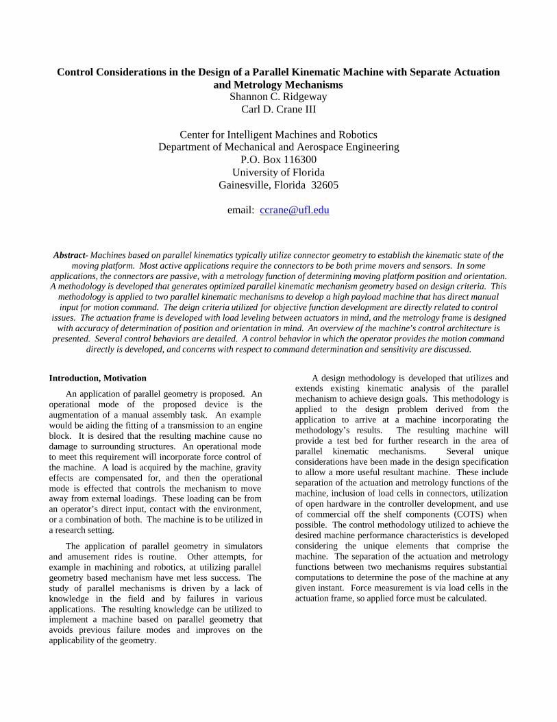
Previous work has shown the accurate measurement of connector length to be difficult due to force and heat based deflections1, 2, 3. One of the design problem’s goals is the production of a research test bed that will allow further study of the PKM and its implementation. It is also anticipated that the design criteria applicable to the actuation of the solution may not necessarily be applicable to the metrology function of the machine. A novel concept is introduced whereby the two functions are separated. A metrology PKM and an actuation PKM are to be combined to arrive at a design solution. This methodology does add complexity to the control scheme. A forward position analysis is necessary to effect control if the actuation connectors are not directly instrumented. A closed form forward position analysis exists for some geometric configurations of the connector joints of PKMs. A mechanism of the special 6-6 variety, for which a closed form forward position analysis exists will be employed for the metrology PKM4. The Special 6-6 confines 3 connector joints to lie at the vertices of a triangle that makes up the fixed and moving platforms. The remaining three joints per platform are required to lie on the line connecting two vertices, or the side of the triangle. Figure 2 illustrates the special 6-6 configuration with symmetry. The triangles making up the platforms are equilateral, and the displacement along the side from a vertex to an intermediate connection is uniform for all three sides of a platform. Table 2 details the parameters utilized to define the special 6-6 geometry.
Term Definition Parallel Kinematic Mechanism: PKM
A mechanism consisting of two bodies connected by two or more struts.
Connector Strut or leg that connects the two bodies of a PKM.
Connector joint Kinematic connection between the connector and fixed or moving platform.
Fixed platform The grounded body of a PKM.
Moving platform The moving body of a PKM Forward analysis Determination of moving
platform properties as a function of connector properties.
Reverse analysis Determination of connector properties as a function of moving platform properties.
Connector
Fixed Platform
Moving Platform
Connector Joint
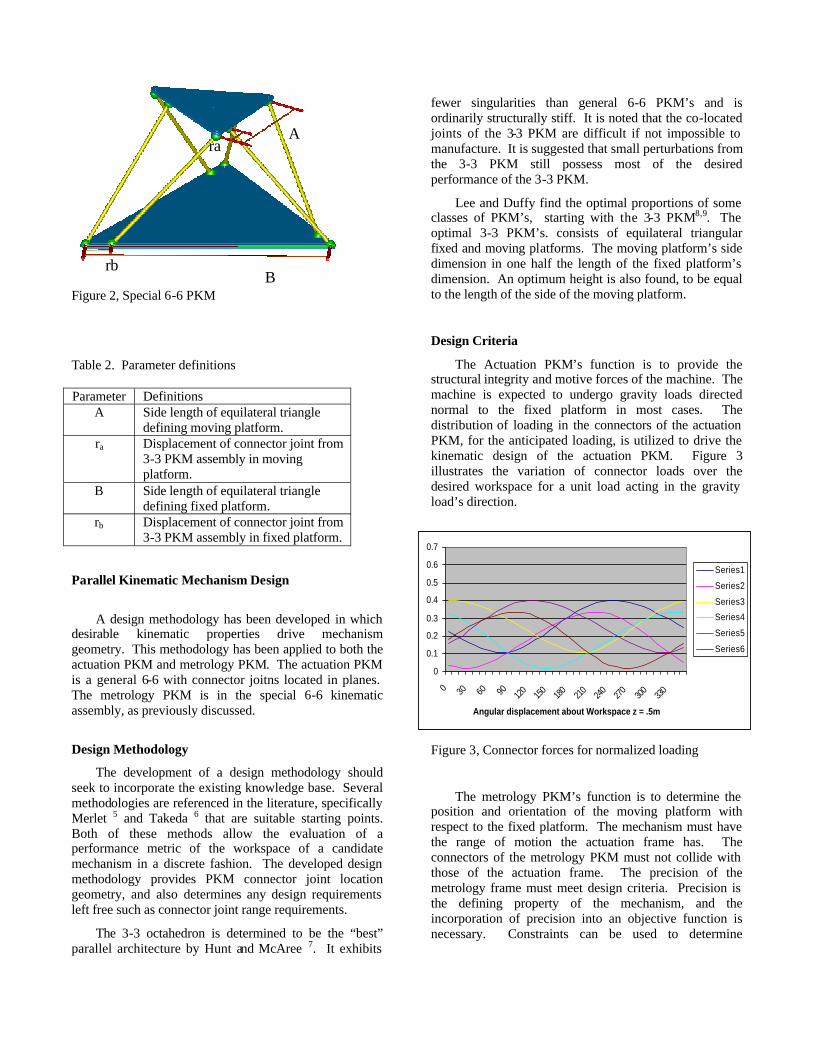
Figure 2, Special 6-6 PKM
Table 2. Parameter definitions
Parallel Kinematic Mechanism Design
A design methodology has been developed in which desirable kinematic properties drive mechanism geometry. This methodology has been applied to both the actuation PKM and metrology PKM. The actuation PKM is a general 6-6 with connector joitns located in planes. The metrology PKM is in the special 6-6 kinematic assembly, as previously discussed.
Design Methodology
The development of a design methodology should seek to incorporate the existing knowledge base. Several methodologies are referenced in the literature, specifically Merlet 5 and Takeda 6 that are suitable starting points. Both of these methods allow the evaluation of a performance metric of the workspace of a candidate mechanism in a discrete fashion. The developed design methodology provides PKM connector joint location geometry, and also determines any design requirements left free such as connector joint range requirements.
The 3-3 octahedron is determined to be the “best” parallel architecture by Hunt and McAree 7. It exhibits
fewer singularities than general 6-6 PKM’s and is ordinarily structurally stiff. It is noted that the co-located joints of the 3-3 PKM are difficult if not impossible to manufacture. It is suggested that small perturbations from the 3-3 PKM still possess most of the desired performance of the 3-3 PKM.
Lee and Duffy find the optimal proportions of some classes of PKM’s, starting with the 3-3 PKM8,9. The optimal 3-3 PKM’s. consists of equilateral triangular fixed and moving platforms. The moving platform’s side dimension in one half the length of the fixed platform’s dimension. An optimum height is also found, to be equal to the length of the side of the moving platform.
Design Criteria
The Actuation PKM’s function is to provide the structural integrity and motive forces of the machine. The machine is expected to undergo gravity loads directed normal to the fixed platform in most cases. The distribution of loading in the connectors of the actuation PKM, for the anticipated loading, is utilized to drive the kinematic design of the actuation PKM. Figure 3 illustrates the variation of connector loads over the desired workspace for a unit load acting in the gravity load’s direction.
Figure 3, Connector forces for normalized loading
The metrology PKM’s function is to determine the position and orientation of the moving platform with respect to the fixed platform. The mechanism must have the range of motion the actuation frame has. The connectors of the metrology PKM must not collide with those of the actuation frame. The precision of the metrology frame must meet design criteria. Precision is the defining property of the mechanism, and the incorporation of precision into an objective function is necessary. Constraints can be used to determine
Parameter Definitions A Side length of equilateral triangle
defining moving platform. ra Displacement of connector joint from
3-3 PKM assembly in moving platform.
B Side length of equilateral triangle defining fixed platform.
rb Displacement of connector joint from 3-3 PKM assembly in fixed platform.
0
0.1
0.2
0.3
0.4
0.5
0.6
0.7
0 30 60 90 120
150
180
210
240
270
300
330
Angular displacement about Workspace z = .5m
Series1
Series2
Series3
Series4
Series5
Series6
B rb
A ra

candidate mechanisms that meet the above remaining criteria.
The geometry of the candidate metrology PKM’s is restricted to the special 6-6 PKM, for which a reverse kinematic analysis exists4. The geometry of the actuation frame applies constraints on the workspace of candidate PKM’s for the metrology application.
Utilizing an objective function based on the propagation of measurement errors through the forward analysis, a geometry is found for the metrology PKM10. Average error for any one of a set of reference points located in the moving platform is 0.00075 m for a connector measurement precision of 0.00002 m.
Figure 4 illustrates the assembled machine. The actuation frame connectors are made up of a COTS hydraulic cylinder, a two stage servo-hydraulic valve, and a load cell. The fixed platform connector joint is a COTS u-joint, the moving platform connector joint is a COTS u-joint modified to incorporate a third orthogonal rotation, effectively making this joint a spherical joint.
Figure 4, Parallel Kinematic Machine
The metrology frame connector structure is provided by a linear recirculating ball bearing slide. Instrumentation is via a linear encoder with a 20 µm scale. The fixed and moving platform connector joints are spherical rolling element joints, each having three degrees of freedom.
Control Methodology The overall control system architecture is shown in Figure 5. The system hardware (actuation frame and metrology frame) is shown below the horizontal dashed line and the control system above the line. Simply put, the control system’s primary function is to generate instantaneous commanded position and velocity commands for the actuation frame hydraulic actuators. These commanded values are based on either (1) desired values that are generated from a path planning algorithm (position control mode) or (2) the current pose of the platform and the current applied external wrench (force control mode).
Metrology Frame Actuation Frame

Figure 5, System Control Architecture
The portion of the controller for the machine that is depicted in the software section of Figure 5 is implemented in a rack mounted pc. The hardware that comprises the interface between the control computer and the actuation and metrology frame is housed primarily on a carrier card located in the PCI bus of the motherboard of the control computer. This hardware consists of the following components: carrier card, digital to analog converter, encoder interface, analog to digital converter, and general input/output.
The control architecture implements the two desired control behaviors. One is a typical path following control in which the system is given a trajectory, and it controls the machine along the trajectory. The second is a reflexive type of control, in which forces on the moving
platform are measured and the resultant force is calculated. The direction of this resultant force is taken as the commanded direction, and the magnitude is taken as the level of effort along the direction. If the machine is subject to a continuous force, for instance, a gravity load, the continuous force can be removed from the force balance.
The second control mode can be driven by an operator directly manipulating the moving platform. It should be noted that the velocities of the moving platform are such that the system may be modeled quasi-statically. In this control mode, the moving platform with reflexively move away from operator input and from environmental interference, making the machine useful for obstacle avoidance in an unstructured environment. Currently, the moving platform loading is measured with load cells in each connector. It is anticipated that
Software
Hardware
User Specified
Metrology Connector
Connector
Parameters (D to A)Commanded Connector
Platform Connector Hardware
Parameters
Platform Parameters Parameters
Measured Top
Force Control
Metrology Connector
Interface (encoder)
Actuation Connector
Controller Interface
Servo ValveAmplifiers
ActuationConnector
MetrologyConnector
Forward Analysis
PathPath Planning
Reverse Analysis
Command Generation
Compensation
Performance
Commanded Connector
System DynamicCommand
EvaluationOf Simulated System
Model
Desired ConnectorParameters
Parameters
Reverse Analysis
Off-Line Control
Position Control
ConnectorLoad cell
Connector Load Cell
Interface (A to D)
Actuation

performance will be adequate. If performance is not acceptable, the load cells can be replaced with elastic elements with length measurement.
Conclusion and Discussions
This paper has introduced a parallel kinemtaic machine based on two parallel kinematic mechanisms. The PKM’s were designed with control issues as driving factors. Consideration of load balance between actuation connectors drove the actuation PKM design. Error propagation from connector space to moving platform space was considered in the design of the metrology PKM. These considerations are incorporated into the control methodology.
The load cells utilized in implementing the force measurement for the moving platform have a bandwidth of approximately 30 Hz. The sensitivity is such that the manual application of force should be detectable, but the resolution of the magnitude of the applied force may not be sufficient to allow the calculation of the force’s direction with a useable precision. As mentioned above, replacement of this component with a more sensitive measurement scheme will alleviate this concern.
Acknowledgements
The authors would like to gratefully acknowledge the support of the United States Department of Energy for their support of this work.
References 1. Patel, A. J., and Ehmann, K. F. Volumetric Error
Analysis of a Stewart Platform Based Machine Tool. Annals of CIRP, Vol. 46/1/1997, pp. 287-290.
2. Soon, J. A. Error Analysis of a Hexapod machine
Tool. Third International Conference and Exhibition on laser Metrology and Machine Performance, Huddersfield, W. Yorkshire,UK. July 15-17, 1997.
3. Wavering, A. J., Parallel Kinematic machine
Resaearch at Nist: Past, Present, and Future. 1st European-American Forum on Parallel Kinematics Machines, Milan, Italy, August 31-September 1, 1998.
4. Griffis et al. Method and Apparatus for Controlling
Geometrically Simple Parallel Mechansims with Distinctive Connections, United States Patent, patent # 5179525, 1993.
5. Merlet, J.P Determination of the Orientation Workspace of Parallel Manipulators. Journal of Intelligent and Robotic Systems. Vol 13, 1995: pp 143-160.
6. Takeda, Y. and Funabashi, H., Kinematic Synthesis of
In-Parallel Actuated Mechanisms Based on the Global Isotropy Index. Journal of Robotics and Mechatronics, Vol 11 No. 5, 1999, pp 404 -410.
7. Hunt, K. H. and McAree, P. R., 1998. Octahedral
Manipulator: Geometry and Mobility. International Journal of Robotics Research, Vol. 17, No. 8, pp. 868-885.
8. Lee, J., Duffy, D., Hunt, K. H., 1998, A Practical
Quality Index Based on the Octahedral Manipulator, The International Journal of Robotics Research, 17/10:1081-1090.
9. Lee, J., and Duffy. J., 1999. The Optimum Quality
Index for Some Spatial In-parallel Devices. Florida Conference on Recent Advances in Robotics, Gainesville, Florida.
10. Ridgeway, S. and Crane, C., 2004. Design
Methodology for Parallel Kinematic Mechanisms Considering Metrology Performance. 10th International Conference on Robotics and Remote Systems for Hazardous Environments, Gainesville, Florida. March 28-31 2004.


![Kinematic [The 38th Parallel]](https://static.fdocuments.net/doc/165x107/568c52151a28ab4916b5401b/kinematic-the-38th-parallel.jpg)
