CONTROL BOX WITH INVERTER - EBARA Pumps Europe...
33
Transcript of CONTROL BOX WITH INVERTER - EBARA Pumps Europe...


CONTROL BOX WITH INVERTER HERTZ ONE
CONTENTS
100
EBARA PUMPS EUROPE S.p.A.
Page
CONTENTS 100
INTRODUCTION 102
DESCRIPTION AND SPECIFICATIONS 200 MODEL RANGE 200 BASIC FUNCTIONING 201 MOTOR REQUIREMENTS 201 SINGLE PHASE HERTZ ONE - COMPOSITION 202 - FEATURES 202 - EBARA PUMPS THAT CAN BE CONNECTED 202 - EBARA GROUPS THAT CAN BE CONNECTED 202 - SPECIFICATIONS 203 - FUNCTIONS 204 - DISPLAY 204 THREE PHASE HERTZ ONE - COMPOSITION 205 - FEATURES 205 - EBARA PUMPS THAT CAN BE CONNECTED 205 - SPECIFICATIONS 206 - FUNCTIONS 207 - DISPLAY 207 SERIAL COMMUNICATION OPTION 208 - HERTZ ONE NETWORKING 208
CONSTRUCTION 300 CONTROL BOX FRONTAL VIEW - CONTROL BOX SINGLE PUMP 300 - CONTROL BOX TWO PUMPS 301 - CONTROL BOX THREE PUMPS 302 INTERNAL DRAWING WITH MAIN COMPONENTS - CONTROL BOX THREE PUMPS 303 DISPLAY PANEL CHARACTERISTICS - FRONT PANEL 304 - HOW TO READ PARAMETERS ON DISPLAY 305 - PROGRAMMING 307

CONTROL BOX WITH INVERTER HERTZ ONE
CONTENTS
101
EBARA PUMPS EUROPE S.p.A.
- PROGRAMMING PARAMETERS TABLE 308
ELECTRICAL CONNECTIONS 400 - GENERAL SAFETY WARNINGS 400 - CONNECTIONS IN A THREE PUMPS CONTROL BOX 401
CONNECTIONS FOR REMOTE PC MANAGEMENT OF CONTROL BOX 402 THREE PHASE CONTROL BOX CONNECTIONS IN A MASTER/SLAVE SYSTEM 403
DIMENSIONS AND WEIGHT 500 DIMENSIONS 500 CONNECTION CABLES 501 WEIGHT 502
APPENDIX 600 PUMP SELECTION ON A VARIABLE SPEED SYSTEM - SINGLE PUMP- CONSTANT PRESSURE HERTZ ONE PUMP SELECTION ON A VARIABLE SPEED GROUP 600 - INTRODUCTION 601 - THREE PUMPS- CONSTANT PRESSURE HERTZ ONE 601 - THREE CONTROL BOXES HERTZ ONE THREE PHASE NETWORK - CONSTANT PRESSURE 601

CONTROL BOX WITH INVERTER HERTZ ONE INTRODUCTION
102
EBARA PUMPS EUROPE S.p.A.
HERTZ ONE SERIES The new HERTZ ONE control box is an automatic device for the control of single or three phase centrifugal electropumps equipped with induction motor. Supply of the control box is only single phase. PRINCIPLE The HERTZ ONE control box is designed to adjust the speed of centrifugal pumps through an inverter (electronic frequency converter) that supplies their motor. Pump capacity and head vary according to the speed of rotation hence offering best efficiency for a wide range of operating conditions (Fig.101)
0
20
40
60
80
100
0 20 40 60 80 100 120 140
Capacity [l/min]
He
ad
[
m ]
Reduced speed
Rated speed
76%
63%70%
74%
76%
74%
70%
77%77%
Fig.101 – Pump performance variation with speed
The settings allow to keep a constant pressure after a change of capacity. The speed variation presents the following advantages compared to a throttling valves regulation:
- Energy saving (less specific energy) - Better and faster regulation, - Reduction of water hammering thanks to a gradual starting and stop, - Enhanced comfort in heating, conditioning and booster systems, - Lower noise levels with reduced loads, - Considerable reduction in the volume of storage systems.
The use of an inverter provides the following advantages:
- Reduced starting current, - Better thermal protections against overloads.

CONTROL BOX WITH INVERTER HERTZ ONE
DESCRIPTION AND SPECIFICATIONS
200
EBARA PUMPS EUROPE S.p.A.
MODEL RANGE The product HERTZ ONE with single phase output is available for one, two or three electropumps. The product HERTZ ONE with three phase output can control only one electropump. Systems with many three phase electropumps have their single boxes (if equipped with transmission option) connected through a serial network RS485 (a simple phone line) in order to create a MASTER / SLAVE (where each pump is controlled through an inverter).
Electropump(s) output Input
Variable speed Constant speed Motor type Optional
No.1 --- Single phase
No.1 No.1 Single phase
No.1 No.2 Single phase Single phase
No.1 --- Three phase
Serial communication card (RS 232, RS 485)
TYPE KEY: Example: HZ ONE 1x1,1M
HZ ONE 1x 1,1 M HZ ONE Inverter name
1x No. of pumps that can be connected
2x
3x 1,1 Max power for each pump [kW] 1,5
M Single phase pump supply = M Single phase pump supply = MX with buster exchange Three phase pump supply = T

CONTROL BOX WITH INVERTER HERTZ ONE
DESCRIPTION AND SPECIFICATIONS
201
EBARA PUMPS EUROPE S.p.A.
BASIC FUNCTIONING SINGLE PUMP VERSION When the system pressure drops below the setpoint value, the HERTZ ONE controller starts the electropump. The box detects the system pressure through a transmitter and keeps it constant with an error lower than 0.1 bar. When water demand ceases, the pressure tends to increase and exceed the setpoint. The controller will then stop the pump (in a non transitional situation). TWO OR THREE PUMPS VERSION When the system pressure drops below the setpoint value, the HERTZ ONE controller starts the inverter-driven electropump. The system pressure is detected through a transmitter and is kept constant with an error lower than 0.1 bar. The controller adjusts the pump speed till the user setpoint is reached. In case the user sets a head value that cannot be reached with a single pump, the HERTZ ONE starts another of the two pumps that are directly supplied by the single phase line. The controller, through a continuous check of the system pressure, keeps adjusting the inverter-driven electropump in order to maintain the preset pressure and switches back to the single inverter-driven pump working mode when possible. If working load increases (this means that two electropumps are not enough to keep the preset pressure) the HERTZ ONE controller will start a third pump (if available). The HERTZ ONE controller will always adjust the inverter-driven electropump in order to maintain the preset pressure also in case that three pumps are running. Working conditions are continuously detected in order to work with the lowest number of pumps possible. The equal use of pump no.2 and 3. is ensured by recalculating the starting sequence at every restart. When pressure reaches the preset value, all pumps are switched off. Electropumps 2 and 3 can be driven by pressure switches (when connected) in case of inverter failure. MOTOR REQUIREMENTS Asynchronous motors (pump motors) used with a HERTZ ONE controller are the same motors that can be used in standard applications, since much attention was put on the fact that the inverter-generated wave does not create tension peaks on the auxiliary winding (if not the insulation could fail in case of single phase motors). For three phase applications the supply tension of the three phase pump is 230V (delta connection).

CONTROL BOX WITH INVERTER HERTZ ONE
DESCRIPTION AND SPECIFICATION
202
EBARA PUMPS EUROPE S.p.A.
SINGLE PHASE HERTZ ONE COMPOSITION The HERTZ ONE control box is composed of:
- Auxiliary starting circuits and electropumps protection, - Frequency converter no.1 for pump governing, - Control and regulation board with display, - Auxiliary circuits, - EMC compliant filter, - Start/stop keys for each electropump with luminous signalling, - Disconnecting switch with door lock.
FEATURES The main HERTZ ONE features are synthesized below:
- Control and regulation of a pump or of a group of pumps according to the better logic for the application needs,
- Starting of pump no.1 with speed adjustment, starting and monitoring of the remaining pumps through relay,
- In case of groups, uniform distribution of the load among the pumps, - Ensure automatic working in case of emergency, - Avoid excessive starting per hour. - Protect motors and inverter with relative alarms - Ensure people’s safety
EBARA PUMPS THAT CAN BE CONNECTED
SERIES SINGLE PHASE MODEL MD MD 32-125/1.1M
EVM EVM3 9N5/1.1 – EVM 3 11N5 1.1 EVM5 6N5/1.1 – EVM10 3N5/1.1
JES – JE / JESX –JEX JESM 8 – JEM 120 – JESXM8 – JEXM 120 AGA – AGE – AGF AGA 100M – AGE 0.80M – AGF 0.80M
CMA – B – C CMA 100M – CMB 100M – CMC 100M - CDA CDA 100 M
COMPACT COMPACT AM/12 – COMPACT BM/12 CVM CVM AM/12 – CVM AM/15 - CVM B/12
MULTIGO MULTIGO M40/15 – MULTIGO M80/15 PRA PRA 1.00M
IDROGO IDROGO M40/15 – IDROGO M80/15 WINNER Motor OY up to 1.1, motor WY up to 0.75
DW DWM 100 M CD – CDX – 2CD – 2CDX CDM 120/12 – CDXM 120/12 – 2CDM 70/12 –
2CDXM 70/12 MATRIX Please check current conditions on page 203
The table shows the pumps with max power input allowed by the single phase HERTZ ONE control box. Pumps with lower power input can be connected too.
EBARA GROUPS THAT CAN BE CONNECTED GP COMPACT – CDXM – CMA – CDA – MULTIGO – CVM - EVM (Max size of pump that can be connected is shown on the previous paragraph table)
CONTROL BOX WITH INVERTER HERTZ ONE
DESCRIPTION AND SPECIFICATION
203
EBARA PUMPS EUROPE S.p.A.
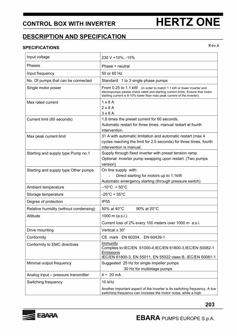
SPECIFICATIONS
Input voltage 230 V +10%, -15%
Phases Phase + neutral
Input frequency 50 or 60 Hz
No. Of pumps that can be connected Standard: 1 to 3 single phase pumps
Single motor power From 0.25 to 1.1 kW (in order to match 1.1 kW or lower inverter and electropumps please check rated and starting current limits. Ensure that motor starting current is 8-10% lower than max peak current of the inverter).
Max rated current 1 x 8 A 2 x 8 A 3 x 8 A
Current limit (60 seconds) 1,6 times the preset current for 60 seconds. Automatic restart for three times, manual restart at fourth intervention.
Max peak current limit 31 A with automatic limitation and automatic restart (max 4 cycles reaching the limit for 2.5 seconds) for three times, fourth intervention is manual.
Starting and supply type Pump no.1 Supply through fixed inverter with preset tension ramp. Optional: Inverter pump swapping upon restart. (Two pumps version)
Starting and supply type Other pumps On line supply with: - Direct starting for motors up to 1.1kW
Automatic emergency starting (through pressure switch) Ambient temperature –10°C + 50°C
Storage temperature -25°C + 55°C
Degree of protection IP55
Relative humidity (without condensing) 50% at 40°C 90% at 20°C
Altitude 1000 m (a.s.l.)
Current loss of 2% every 100 meters over 1000 m a.s.l.
Drive mounting Vertical ± 30°
Conformity CE mark EN 60204, EN 60439-1
Conformity to EMC directives Immunity Complies to:IEC/EN 61000-4,IEC/EN 61800-3,IEC/EN 50082-1 Emissions IEC/EN 61800-3, EN 55011, EN 55022 class B, IEC/EN 50081-1
Minimal output frequency Suggested 25 Hz for single impeller pumps 30 Hz for multistage pumps
Analog input – pressure transmitter 4 ÷ 20 mA
Switching frequency 10 kHz Another important aspect of the inverter is its switching frequency. A low switching frequency can increase the motor noise, while a high

CONTROL BOX WITH INVERTER HERTZ ONE
DESCRIPTION AND SPECIFICATION
204
EBARA PUMPS EUROPE S.p.A.
switching frequency requires the inverter to be equipped with high power components as well as an efficient cooling system.
FUNCTIONS
Working Dual possibility: ● During normal working the group gets a signal from the pressure transmitter and by means of the inverter-equipped control box it detects the speed of pump no.1, starting the remaining pumps in sequence, by contactors. Alternate starting of electropumps 2 and 3 ● By PRESSURE SWITCHES (if connected) the group (inverter is excluded) replies to the signal from the pressure transmitter of every single pump, and keeps the preset pressure field constant. The working mode by pressure switches is automatically activated in case of inverter or pressure transmitter failure (the inverter-driven pump is excluded in the pressure switch mode)
Motor protections - Against overload - Against short-circuits (12 A fuses AM type) - Automatic restart with a reference pressure reduced of 0.5 bar to avoid
continuous restarts Pump protections - Against dry running (inverter-driven pump is stopped after a minute of shut-off
working) - Against overpressure - Monitoring of working hours for each electropump
Inverter protections - Against overload - Against short circuits (10A fuses type Gg)
Distance control - Control of each pump by pressure switch - Control of the system by pressure transmitter
SIGNALLING
Indications - Four digit LED for INVERTER control box parameters Luminous signals
- Pumps running - Pumps enabled at startup - Generic alarm for any of the following cases: - Motor maintenance, wrong parameters, transmitter failure, electrical connections
interruption, pumps overload, inverter alarm, overpressure, minimal pressure Distance signals By potential free contacts (contact N.A. 5A 250V)
A pair of connectors collects the following alarms: - Lack of water or minimal pressure - Overpressure - No signal from the pressure transmitter - Inverter alarm - Motor overload A dual-output module (RS485 and RS232) for PC software monitoring of the system is available upon request. RS232 output is suitable for use with a local PC RS485 output is suitable for use with a remote PC (an adaptor from RS485 to

CONTROL BOX WITH INVERTER HERTZ ONE
DESCRIPTION AND SPECIFICATION
205
EBARA PUMPS EUROPE S.p.A.
RS232 is required for the control PC)
THREE PHASE HERTZ ONE (one pump only) COMPOSITION Control box is composed of:
- Frequency converter for three phase pump governing, - Control and regulation board with display, - Auxiliary circuits, - EMC compliant filter,
FEATURES The main features are synthesized below:
- Control and regulation of a pump or of a group of pumps when a network of control boxes is installed - Starting of pump no.1 with speed adjustment, - In case of groups, uniform distribution of the load among the pumps, - Avoid excessive startings per hour - Protect motors and inverter with relative alarms - Ensure people’s safety
EBARA PUMPS THAT CAN BE CONNECTED
SERIES THREE PHASE MODEL EVM EVM3 9N5/1.1 – EVM5 5N5/1.1
EVM 5 6N5/1.1 - EVM10 3N5/1.1 JES – JE / JESX –JEX JES8 – JE120 – JESX8 – JEX120
AGA – AGE – AGF AGA 1.00T – AGE 0.80T – AGF 0.80T CMA – B – C CMA 1.00T – CMB 1.00T – CMC 1.00T
CDA CDA 1.00T COMPACT COMPACT A/12 – COMPACT B/12
CVM CVM A/15 – CVM B/15 PRA PRA 1.00
CD – CDX – 2CD – 2CDX CD 200/12 DWC DWC 300/1.1
MATRIX Please check current conditions on page 206 The table shows the pumps with max power input allowed by the three phase HERTZ ONE control box.

CONTROL BOX WITH INVERTER HERTZ ONE
DESCRIPTION AND SPECIFICATION
206
EBARA PUMPS EUROPE S.p.A.
SPECIFICATIONS
Input voltage 230 V +10%, -15%
Phases Phase + neutral
Input frequency 50 or 60 Hz
No. Of pumps that can be connected 1 three phase
Single motor power From 0.25 to 1.1 kW (three phase motor delta connection) (in order to match 1.5 kW inverter and electropumps please check rated and starting current limits. Ensure that motor starting current is 8-10% lower than max peak current of the inverter).
Max rated current 1 x 8 A
Current limit (60 seconds) 1,6 times the preset current for 60 seconds. Automatic restart for three times, manual restart at fourth intervention.
Max peak current limit 31 A with automatic limitation and automatic restart (max 4 cycles reaching the limit for 2.5 seconds) for three times, fourth intervention is manual.
Starting and supply type Pump no.1 Supply through fixed inverter with preset tension ramp
Ambient temperature –10°C + 50°C
Storage temperature -25°C + 55°C
Degree of protection IP55
Relative humidity (without condensing) 50% to 40°C
90% to 20°C
Altitude 1000 m (a.s.l.);
Current loss of 2% every 100 meters over 1000 m a.s.l.
Drive mounting Vertical ± 30°
Conformity CE mark
EN 60204, EN 60439-1
Conformity to EMC directives
Immunity Complies to IEC/EN 61000-4, IEC/EN 61800-3, IEC/EN 50082-1 Emissions IEC/EN 61800-3, EN 55011, EN 55022 class B, IEC/EN 50081-1
Minimal output frequency Suggested 25 Hz for single impeller pumps 30 Hz for multistage pumps
Analog input – pressure transmitter 4 ÷ 20 mA

CONTROL BOX WITH INVERTER HERTZ ONE
DESCRIPTION AND SPECIFICATION
207
EBARA PUMPS EUROPE S.p.A.
FUNCTIONS
Working: The group gets a signal from the pressure transmitter and by means of the inverter-equipped control box it controls the speed of pump no.1. Alternate starting of electropumps 2 , 3 and 4 achieved through their respective control boxes .
Motor protections - Against overload - Against short-circuits (12 A fuses AM type) - Automatic restart with a reference pressure reduced of 0.5 bar to avoid
continuous restarts Pump protections
- Against dry running (automatic stop, after a minute, of the inverter supplied pump with capacity = 0 litres/min).
- Against overpressure - Monitoring of working hours of electropump
Inverter protections - Against overload - Against short circuits (10A fuses type Gg)
Distance controls - Control of the system by pressure transmitter.
SIGNALLING
Indications - Four digit LED for INVERTER control box parameters. Luminous signals - Pump running
- Pump enabled at startup. - Generic alarm for any of the following cases:- - Motor maintenance, wrong parameters, transmitter failure, electrical connections
interruption, pump overload, inverter alarm, overpressure, minimal pressure
Distance signals By potential free contacts (contact N.A. 5A 250V) A pair of connectors collect the following alarms: - Lack of water or minimal pressure - Overpressure - No signal from the pressure transmitter - Inverter alarm - Motor overload An-output module (RS485 and RS232) for PC software monitoring of the system is available upon request. This option is only available for a single-pump system In order to connect multiple three phase HERTZ ONE the RS485 serial output must be used, then the remaining RS232 serial output must be connected to a PC based monitoring software.

CONTROL BOX WITH INVERTER HERTZ ONE
CONSTRUCTION
208
EBARA PUMPS EUROPE S.p.A.
SERIAL COMMUNICATION OPTION A serial communication module for PC monitoring and programming of single or multiple frequency converters is available upon request. The software displays the following information:
- frequency of the inverter-driven pump - system pressure - set pressure - single pumps status - system parameters can be edited; - alarm signalling (maintenance, wrong parameters transmitter failure, thermal alarms inverter fault,
danger ;
The optional module is equipped with 2 serial ports:
- RS232 - RS485
The choice between the two ports depends on the distance from the controller to the PC. The RS485 standard can transmit the signal to hundreds of meters (up to 1 km), while shorter distances (up to 10 m) can be reached by the RS232 standard The RS232 standard allows a direct connection to the PC (if a port is available) with a DB9 connector ( 9 pins) The RS485 standard requires an adaptor from RS485 to RS232 on the PC. The required cable for RS485 is made of two twisted wires of about 10 rounds per meter and a third wire as reference. Connections made of non-twisted wires are not suitable (unless used for a few centimetres in a low interferences ambient and low speed. In order to obtain good performances (in terms of interferences) a shielded cable must be used. HERTZ ONE NETWORKING The three phase HERTZ ONE (inverter single-phase supply, electropump three-phase supply) can be connected in a network. The maximum number of HERTZ ONE that can be connected is four. (1 MASTER and 3 SLAVES). The above-mentioned configuration can be obtained by inserting the optional module described on paragraph “Serial communication option”. All HERTZ ONE control boxes connections are RS485 standard. The pressure transmitter is connected to the controller terminal identified as Master, the others SLAVE controllers get the pressure signal in chain (MASTER – SLAVE1 – SLAVE2 – SLAVE3). The system obtained is commanded by the MASTER, and the differences with the previous types are described below.
- Supply of the electropumps is three phase; - Each electropump speed is modulated by its respective inverter; - Pumps starting sequences is modified every restart.
When many three phase HERTZ ONE are connected together the port RS485 is no longer available (as already used) for the connection with a PC. In this case the serial port RS232 of the MASTER HERTZ ONE must be used (max distance for connection:10 mt).

CONTROL BOX WITH INVERTER HERTZ ONE
CONSTRUCTION
300
EBARA PUMPS EUROPE S.p.A.
CONTROL BOX FRONTAL VIEW CONTROL BOX SINGLE PUMP
Pos. COMPONENTS Pos. COMPONENTS
1 Disconnecting switch 7 ÷ 9 Signalling LED
2 Frontal of the System Controller board 14 STOP KEY (disable pump for automatic run)
3 ÷ 6 Keys to confirm, edit , increase and decrease the electronic control parameters 15 START KEY (enable pump for automatic run)

CONTROL BOX WITH INVERTER HERTZ ONE
CONSTRUCTION
301
EBARA PUMPS EUROPE S.p.A.
CONTROL BOX FRONTAL VIEW CONTROL BOX TWO PUMPS
Pos. COMPONENTS Pos. COMPONENTS
1 Disconnecting switch 7 ÷ 11 Signalling LED
2 Frontal of the system controller board 14 ÷ 15 Stop / Start key Pump 1
3 ÷ 6 Keys to confirm, edit , increase and decrease the electronic control parameters 16 ÷ 17 Stop / Start key Pump 2

CONTROL BOX WITH INVERTER HERTZ ONE
CONSTRUCTION
302
EBARA PUMPS EUROPE S.p.A.
CONTROL BOX FRONTAL VIEW CONTROL BOX THREE PUMPS
Pos. COMPONENTS Pos. COMPONENTS
1 Disconnecting switch 14 ÷ 15 Stop / Start key Pump 1
2 Frontal of the System Controller board 16 ÷ 17 Stop / Start key Pump 2
3 ÷ 6 Keys to confirm, edit , increase and decrease the electronic control parameters 18 ÷ 19 Stop / Start key Pump 3
7 ÷ 13 Signalling LED

CONTROL BOX WITH INVERTER HERTZ ONE
CONSTRUCTION
303
EBARA PUMPS EUROPE S.p.A.
INTERNAL DRAWING WITH MAIN COMPONENTS CONTROL BOX THREE PUMPS
Pos. COMPONENTS Pos. COMPONENTS
1 Disconnecting switch 3 Fuses
2 Terminal board 4 Inverter electronics transformer

CONTROL BOX WITH INVERTER HERTZ ONE
CONSTRUCTION
304
EBARA PUMPS EUROPE S.p.A.
DISPLAY PANEL CHARACTERISTICS FRONT PANEL The front panel is the interface used to monitor all functions as well as the system pressure. The drawing below is an example of the three pumps version.
(ENTER) key to confirm the entered value.
(SHIFT) key to select the value to edit.
(INCREASE) key to increase the selected value or to access the upper parameters line
(DECREASE) key to decrease the selected value or to access the lower parameters line. The STOP key (one for each pump) is used to disable the current pump. The START key (one for each pump) enables the pump for automatic working, if held more than 5 seconds, it starts the pump. When the key is released the pump is stopped. The yellow LED STANDBY means the pump is ready for startup, the green led ON means the pump is running.

CONTROL BOX WITH INVERTER HERTZ ONE
CONSTRUCTION
305
EBARA PUMPS EUROPE S.p.A.
HOW TO READ PARAMETERS ON DISPLAY The parameters shown on the display in the view mode (when the programming mode is off, no password inserted) are listed on table 1. Keys INCRESE e DECREASE are used to browse trough the parameters. When the HERTZ ONE Is activated the actual system pressure is displayed (all LEDS are off as well as all pumps). Tab.1
DISPLAY DESCRIPTION P 00.0
Actual system pressure. (bar)
r 00.0 Set pressure. (bar)
Inv0 HERTZ ONE models with inverter pump swapping only shows pump currently driven by inverter Inv1: inverter activated on pump no.1 Inv2: inverter activated on pump no.2
F 00.0 Inverter supplied motor frequency (Hz)
A 00.0 Inverter supplied Pump no.1 motor input (Ampere)
b 00.0 Pump no.2 motor input (Ampere)
c 00.0 Pump no.3 motor input (Ampere)
An1 Working hours pump no.1. 1 unit= 10 working hours
An2 Working hours pump no.2. 1 unit= 10 working hours
An3 Working hours pump no.3. 1 unit= 10 working hours
PSET System pressure to be kept constant CP Proportional correction of the error between the system pressure and
the reference pressure PSET (decrease the value in case of excessive pressure fluctuations, increase the value if pressure drops excessively at startup.)
AL0 Alarms memory SrE1 Software version PASS Password to be entered: 2222

CONTROL BOX WITH INVERTER HERTZ ONE
CONSTRUCTION
306
EBARA PUMPS EUROPE S.p.A.
ALARM CODES AL1 Maintenance alarm: Working hours of TnAm parameter have been exceeded
(PROGRAMMING SET) The alarm does not stop the pumps, that will keep running In addition to the display warning the alarm red LED is on.
AL2 Programming error due to: PSET>Pn or Pn>PFS (from the pressure transmitter). This alarm stops all pumps and the red LED alarm is on Pump P1 (inverter driven) is off Pumps P2 and P3 (if they are available) will work with the pressure switches.
AL4 Sensor failure (it could also be activated in case of disconnection of the sensor cable). This alarm turns off all pumps. If pressure switches connection is activated, pumps 2 and 3 are run by the controller while the inverter driven pump is off The alarm red LED is on.
AL8 Motor overload alarm (three restarts each minute, manual at fourth attempt). If restarts fail, the system controller stops the motor(s) presenting an overload. During the automatic restarts the red LED is flashing, in case of manual intervention , the red LED is on. The following messages are used to identify the defective pump: a 8 = pump P1 fault; b 8 = pump P2 fault; c 8 = pump P3 fault;
AL16 Inverter fault. The inverter driven pump (number 1) is stopped. The controller will run pumps no.2 and no.3 (if they are available) by direct command through pressure transmitter Alarm red LED is on
AL32 Overpressure The controller stops all pumps. When pressure becomes normal with a minimum time of 5 seconds there is a restart. Alarm red LED is on
AL64 Lack of water (three automatic restarts each minute, manual restart at fourth attempt). Alarm red LED is on.
When many alarms are active at the same time the display will show them as sum of the two respective alarms.
- ALARM 12 = ALARMS 4 + 8 - ALARM 24 = ALARMS 8 + 16 - ALARM 68 = ALARMS 4 + 64 - ALARM 72 = ALARMS 8 + 64
As previously described each alarm turns on a red LED (the LED is situated beside the display, with the alarm triangle indication). Below is a drawing of the alarm.

CONTROL BOX WITH INVERTER HERTZ ONE
CONSTRUCTION
307
EBARA PUMPS EUROPE S.p.A.
!
PROGRAMMING To access programming mode, do the following:
Power on the HERTZ ONE box, and when display turns on press till the symbol PASS appears on
the display, then press the key to access the password page. When the value 0 appears, use the key
to select it (value 0 starts flashing). Enter the password 2222. To increase the value 0 to 2 , use the
key and then confirm with . Repeat the above mentioned procedure to set to 2 the second and third digit.
When fourth digit is increased to 2, press At this point the parameters codes will be displayed as described in “Programming parameters table” To browse trough parameter use the key DECREASE. Press any other key to exit the programming mode. To view and edit programming parameters use the key RETURN. When pressed for the first time view and edit of the field is enabled, when pressed for the second time this mode is off. When inside the edit/view field, a pressure of the key SHIFT will cause the first digit of the value to flash (further pressure of the SHIFT key will select the next digit. Keys INCREASE/DECREASE are used to edit the value while the key RETURN confirms the entered value If no key is pressed in 10 min the display will exit the programming mode and display the current system pressure.

CONTROL BOX WITH INVERTER HERTZ ONE
CONSTRUCTION
308
EBARA PUMPS EUROPE S.p.A.
PROGRAMMING PARAMETERS TABLE
PARAMETERS CODE DESCRIPTION FIELD
A Max input motor no.1 (inverter driven) Insert rated current of the motor
0 ÷ 10 (Ampere)
B Max input motor no.2 (direct working motor). Insert rated current of the motor
0 ÷ 10 (Ampere)
C Max input motor no.3 (direct working motor). Insert rated current of the motor
0 ÷ 10 (Ampere)
CI Constant correction of the error between the system pressure and the reference pressure PSET
(a value too high can produce fluctuations. No correction applied if the value is “0”, error instantly corrected if value is “255”
0 ÷ 255
Pn Pump rated pressure with no capacity (0 litres) (insert pump pressure at 0 litres).
0 ÷ 25.5 (bar)
VEL Minimum inverter speed for stopping of pumps 2 and 3. Parameter is calculated based on values at
PSET and Pn
0 ÷ 100 (%)
Pr Restarting pressure. 0,0 ÷ 2 (bar)
Vrp Minimal inverter speed. Below this value the inverter stops
0 ÷ 100 (%)
rP PSET reduction to stop inverter driven pump
0,0 ÷ 2 (bar)
InTr Time interval to enable PSET reduction (inverter driven pump stop)
0,0 ÷ 99 (secondi)
PH20 Minimal pressure for stopping the pumps due to lack of water in suction.
0 ÷ 25.5 (bar)
PPEr Pressure setting at which HERTZ ONE stops all pumps PPEr (Warning P.) = PSET x 1,5 x (Pn-PSET)
0 ÷ 100 (%)
PFS End scale pressure of the pressure transmitter installed on the system
(0 ÷ 10 bar) (0 ÷ 16 bar) (0 ÷ 25 bar)
TIP System kind: one, two or three pumps
1, 2, 3
Addr** Serial port address
0 ÷ 4
SEO Hour of change of starting order Insert a value from 1 to 24 to invert the starting sequence of the
pumps at a specific time of the day. Insert the value 25 to change the sequence at every restart
1 ÷ 25
TnAm* Pump maintenance time (1 unit = 10 working hours)
0 ÷ 9999
CONTROL BOX WITH INVERTER HERTZ ONE
CONSTRUCTION
309
EBARA PUMPS EUROPE S.p.A.
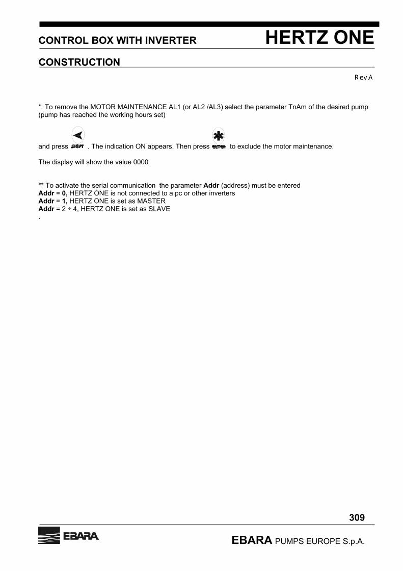
*: To remove the MOTOR MAINTENANCE AL1 (or AL2 /AL3) select the parameter TnAm of the desired pump (pump has reached the working hours set)
and press . The indication ON appears. Then press to exclude the motor maintenance. The display will show the value 0000 ** To activate the serial communication the parameter Addr (address) must be entered Addr = 0, HERTZ ONE is not connected to a pc or other inverters Addr = 1, HERTZ ONE is set as MASTER Addr = 2 ÷ 4, HERTZ ONE is set as SLAVE .

CONTROL BOX WITH INVERTER HERTZ ONE
ELECTRICAL CONNECTIONS
400
EBARA PUMPS EUROPE S.p.A.
GENERAL SAFETY WARNINGS CLASS A differential switches must be installed in the system before the HERTZ ONE control boxes.(the type A differential is tested for sinusoidal as well as pulsating current with a continuous component) with leakage current that can be set till a max of 30 mA, selective and protected against behind time activation with a delay of 0.5 sec. As regards the automatic protection against short-circuits, the supply line must be protected with fuses type “AM” or with magnetotermic switches type D. Please make sure the earth connection is correctly made. The following table shows the correct values of the fuses for the line protection (calculated on max load).
Rated supply tension 230 V – 10%, 230 V +15% Power (kW) of controller HERTZ ONE
Current (A) Fuses type
1 x 1.1 12 A AM – 10 x 38 2 x 1.1 25 A AM – 10 x 38 3 x 1.1 32 A AM – 14 x 51 1 x 1,5 12 A AM – 10 x 38

CONROL BOX WITH INVERTER HERTZ ONE
ELECTRICAL CONNECTIONS
401
EBARA PUMPS EUROPE S.p.A.
CONNECTIONS IN A THREE PUMPS CONTROL BOX
TERMINAL DESCRIPTION ALARM 1 – 2 –3
Terminals for remote signalling of control box alarms (inverter alarm, motor overload, lack of water or minimal pressure, sensor failure)
REMOTE CONT 4 – 5
Terminals for remote control connection. If used, remove the bypass jumper situated between terminals 4 and 5 Input characteristics: 24 Vac 0.04 A
PR:TR 6 – 7 - 9
Terminals for connection of pressure transmitter Input characteristics: 15 Vd.c, 4÷20 mA Terminal: 6 supply 7 signal input 9 screen
PSM2 10 – 11
Cables connected to pressure switch PS1 for control of pump no.2
PSM3 12 – 13
Cables connected to pressure switch PS2 for control of pump no.3
L / N 14 – 15
Connection of pump no.1 to inverter
L / N 16 – 17
Connection of pump no.2
L / N 18 - 19
Connection of pump no.3

CONTROL BOX WITH INVERTER HERTZ ONE
ELECTRICAL CONNECTIONS
402
EBARA PUMPS EUROPE S.p.A.
CONNECTIONS OF CONTROL BOX FOR REMOTE PC MANAGEMENT

CONTROL BOX WITH INVERTERHERTZ ONE
ELECTRICAL CONNECTIONS
403
EBARA PUMPS EUROPE S.p.A.
THREE PHASE CONTROL BOX CONNECTION IN A MASTER/SLAVE SYSTEM

CONTROL BOX WITH INVERTER HERTZ ONE
DIMENSIONS AND WEIGHT
500
EBARA PUMPS EUROPE S.p.A.
DIMENSIONS

CONTROL BOX WITH INVERTER HERTZ ONE
DIMENSIONS AND WEIGHT
501
EBARA PUMPS EUROPE S.p.A.
CONNECTION CABLES Here below are specified all the cables that can be supplied with the control box: The transmitter cable used with the cabinet is 140 cm long instead of 83 cm.

CONTROL BOX WITH INVERTER HERTZ ONE
DIMENSIONS AND WEIGHT
502
EBARA PUMPS EUROPE S.p.A.
WEIGHT SINGLE PUMP CONTROL BOXES TWO PUMPS CONTROL BOXES
MODEL WEIGHT (Kg)
MODEL WEIGHT Kg
HZ ONE 1x1,1M 5,5 HZ ONE 2x1,1M 5,7 HZ ONE 1x1,5T 5,5
THREE PUMPS CONTROL BOXES
MODEL WEIGHT Kg
HZ ONE 3x1,1M 6

CONTROL BOX WITH INVERTER HERTZ ONE
APPENDIX
EBARA PUMPS EUROPE S.p.A.
600
PUMP SELECTION ON A VARIABLE SPEED SYSTEM Single pump HERTZ ONE – constant pressure (Fig.601) Pump must be chosen starting from the basic requirements: - Pressure required (Hset) - Maximum system capacity (Qmax). With the above-mentioned data the hydraulic curves of the variable speed pumps must be checked, and the one that covers the rated pressure field up to Qmax must be selected. This point should be at the right of the maximum efficiency point of the pump, but it should also have an efficiency which is not lower than 10% of the maximum. Possibly, the minimum capacity point should have an efficiency not lower than 10% of the maximum, too.
0
80
0 500
Capacity Q
Head
H
min Speed
Max Speed- 5%
-20%-10%
-10%
-20%
Max eff.
- 5%
Qmax
Hset
The optimal use of the selected pump, as far as energy saving is concerned, is possible when point Qmax-Hset is very close to the pump maximum speed curve. Furthermore, when conditions are particularly critical, a check of the NPSH at the conditions of Qmax-Hset should be performed by calculating the NPSH available for the system. This should be higher than the one requested by the pump at max. speed. Concerning the conditions at reduced speed, the situation becomes less critical as the required NPSH decreases and generally, the available one increases.
Fig.601 : Pump selection in constant pressure system
CONTROL BOX WITH INVERTER HERTZ ONE
APPENDIX
EBARA PUMPS EUROPE S.p.A.
601
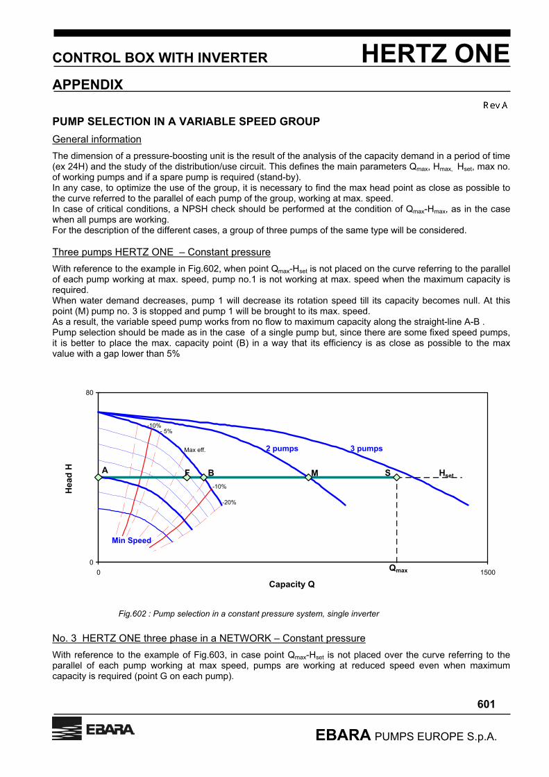
PUMP SELECTION IN A VARIABLE SPEED GROUP General information The dimension of a pressure-boosting unit is the result of the analysis of the capacity demand in a period of time (ex 24H) and the study of the distribution/use circuit. This defines the main parameters Qmax, Hmax, Hset, max no. of working pumps and if a spare pump is required (stand-by). In any case, to optimize the use of the group, it is necessary to find the max head point as close as possible to the curve referred to the parallel of each pump of the group, working at max. speed. In case of critical conditions, a NPSH check should be performed at the condition of Qmax-Hmax, as in the case when all pumps are working. For the description of the different cases, a group of three pumps of the same type will be considered. Three pumps HERTZ ONE – Constant pressure With reference to the example in Fig.602, when point Qmax-Hset is not placed on the curve referring to the parallel of each pump working at max. speed, pump no.1 is not working at max. speed when the maximum capacity is required. When water demand decreases, pump 1 will decrease its rotation speed till its capacity becomes null. At this point (M) pump no. 3 is stopped and pump 1 will be brought to its max. speed. As a result, the variable speed pump works from no flow to maximum capacity along the straight-line A-B . Pump selection should be made as in the case of a single pump but, since there are some fixed speed pumps, it is better to place the max. capacity point (B) in a way that its efficiency is as close as possible to the max value with a gap lower than 5%
0
80
0 1500
Capacity Q
Head
H
Min Speed
3 pumps
- 5%-10%
-10%
-20%
Max eff.
Qmax
Hset
2 pumps
SB MFA
No. 3 HERTZ ONE three phase in a NETWORK – Constant pressure With reference to the example of Fig.603, in case point Qmax-Hset is not placed over the curve referring to the parallel of each pump working at max speed, pumps are working at reduced speed even when maximum capacity is required (point G on each pump).
Fig.602 : Pump selection in a constant pressure system, single inverter

CONTROL BOX WITH INVERTER HERTZ ONE
APPENDIX
EBARA PUMPS EUROPE S.p.A.
602
When water demand decreases, pump 1, 2 and 3 will decrease their rotation speed till capacity Q2-3 (point F on each pump). At this point (M) pump no. 3 is stopped and pump no. 1 and 2 will increase their rotation speed to adjust to the new conditions. After a further decrease of water supply, pumps 1 and 2 will reduce their rotation speed till capacity Q1-2 is reached (point E on each pump). At this point (B) pump no. 2 will stop and pump no.1 will increase its speed to adjust to the new conditions. From this moment till the point of no demand (point A), pump no 1 works individually. As a result, all pumps at variable speed work from no capacity to max capacity along the straight-line A-B but mostly in the field E-B.
0
80
0 1500
Capacity Q
Head
H
Min Speed
3 pumps
- 5%-10%
-10%
-20%
Max efficiency
Qmax
Hset
2 pumps
SB MFA E G
Q1-2 Q2-3
The pump selection should be made as in the case of a single pump, but considering the speed variation of all the group units, it is better to place the maximum capacity point (B) in a way that its efficiency is as close as possible to the max value with a gap lower than 5%. Point E should have good values of efficiency too.
Fig.603 : pump selection in a constant pressure group-Multi-inverter