CONTROL ARCHITECTURE FOR RECONFIGURABLE …CONTROL ARCHITECTURE FOR RECONFIGURABLE AND DISTRIBUTED...
12
CONTROL ARCHITECTURE FOR RECONFIGURABLE AND DISTRIBUTED MANUFACTURING SYSTEM Robson Marinho da Silva Universidade Estadual de Santa Cruz, Ilhéus, BA, Brasil [email protected] Mauricio Fontoura Blos Fabrício Junqueira Diolino José dos Santos Filho Paulo Eigi Miyagi Escola Politécnica da Universidade de São Paulo, São Paulo, SP, Brasil [email protected], [email protected], [email protected],[email protected] Abstract. Control systems for conventional manufacturing systems are designed based on division in scope and control problems organized into hierarchical levels such as, enterprise control, factory control, and shop-floor control. However, currently manufacturing systems must assure integration and reconfiguration flexibility characteristics, i.e., a reconfig- urable manufacturing system must collaborate each other, combining a global vision with a relatively agile reaction to unexpected variations of the shop-floor control level or new businesses processes in enterprise and factory control lev- els. On the other hand, in a global market, control systems must also consider businesses processes of geographically distributed manufacturing systems to take advantages of local facilities. Holonic and Multi-Agent System (HMAS) and Service-Oriented Architecture (SOA) techniques are effective to model control system of RDMS, but a formal method must also be considered to ensure this combination and a systematic application of design specifications. Therefore, this paper proposes models of control architecture for RDMS using bottom–up and top–down approaches through Petri net technique. This models extends a method to model a control system for RDMS based on combination of HMAS and SOA. Fault-tolerant control mechanisms and their application aspects are treated and an application example demonstrates advantages of this proposal, such as autonomy, flexibility, collaboration, reuse and robustness. Keywords: manufacturing system; reconfigurable system; service oriented architecture; holonic and multi-agent system; distributed productive system 1. INTRODUCTION Manufacturing systems have been designed to meet demands of goods production, transforming materials and pro- cessing information based on control functions. These functions were organized into hierarchical levels as Fig. 1a shows: enterprise control — where decisions and control are made in long-term management; factory control — where deci- sions and control are related to ordination of requests and supervision of productive processes; and shop-floor control — where decisions and control are machines operations, which are automatically executed through programmable controllers connected to sensors and actuators (Groba et al., 2008). The growing competitiveness and the need for efficiency imposed changes requiring greater flexibility under different aspects. The evolution is characterized by a gradual migration of manufacturing paradigms: mass manufacturing is con- cerned to cheaper products; lean manufacturing is concerned to continuous quality improvement; flexible manufacturing system is concerned to products diversity; and reconfigurable manufacturing system is concerned to be “adjustable” to business and market interests. Figure 1b shows economic goals associated with this evolution (Mehrabi et al., 2000). Besides, control systems of distributed manufacturing systems in dispersed geographic location with different businesses processes (material transformation and/or information processing) must interact each other (Ali et al., 2005; Garcia Melo et al., 2008) to take advantages of local facilities and expertise. Despite advantages of Reconfigurable and Distributed Manufacturing System (RDMS) paradigm, its implementation is not trivial. There is the need for increasing safety in machines and their controllers, adequate use of resources and for methods that allow qualified staff to update (or replace) legacy systems. Besides, a global vision of the system goal must be combined to autonomous components. These challenges, associated with the lack of quantitative performance data to evaluate these aspects, restrict the expansion of this paradigm (Vrba et al., 2011). For increasing safety, solutions based on Active Fault-Tolerant Control System (AFTCS) (Zhang and Jiang, 2008) involving fault detection, study of its effects, identification of its causes and finally, reconfiguration of the system through relocating and choosing alternative productive processes can be considered. According to Silva et al. (2012a), the control strategy must recover the functionality of the system (also called regeneration) or maintaining operations where parts affected by the fault are disabled without affecting operations in other parts of the system (also called degeneration). Therefore, to ensure that a RDMS meets all their purposes, their control systems must be updated for agile reaction both ABCM Symposium Series in Mechatronics - Vol. 6 Copyright © 2014 by ABCM Part I - International Congress Section I - Modelling, Control & Identification 219
Transcript of CONTROL ARCHITECTURE FOR RECONFIGURABLE …CONTROL ARCHITECTURE FOR RECONFIGURABLE AND DISTRIBUTED...

CONTROL ARCHITECTURE FOR RECONFIGURABLE ANDDISTRIBUTED MANUFACTURING SYSTEM
Robson Marinho da SilvaUniversidade Estadual de Santa Cruz, Ilhéus, BA, [email protected] Fontoura BlosFabrício JunqueiraDiolino José dos Santos FilhoPaulo Eigi MiyagiEscola Politécnica da Universidade de São Paulo, São Paulo, SP, [email protected], [email protected], [email protected],[email protected]
Abstract. Control systems for conventional manufacturing systems are designed based on division in scope and controlproblems organized into hierarchical levels such as, enterprise control, factory control, and shop-floor control. However,currently manufacturing systems must assure integration and reconfiguration flexibility characteristics, i.e., a reconfig-urable manufacturing system must collaborate each other, combining a global vision with a relatively agile reaction tounexpected variations of the shop-floor control level or new businesses processes in enterprise and factory control lev-els. On the other hand, in a global market, control systems must also consider businesses processes of geographicallydistributed manufacturing systems to take advantages of local facilities. Holonic and Multi-Agent System (HMAS) andService-Oriented Architecture (SOA) techniques are effective to model control system of RDMS, but a formal methodmust also be considered to ensure this combination and a systematic application of design specifications. Therefore, thispaper proposes models of control architecture for RDMS using bottom–up and top–down approaches through Petri nettechnique. This models extends a method to model a control system for RDMS based on combination of HMAS and SOA.Fault-tolerant control mechanisms and their application aspects are treated and an application example demonstratesadvantages of this proposal, such as autonomy, flexibility, collaboration, reuse and robustness.
Keywords: manufacturing system; reconfigurable system; service oriented architecture; holonic and multi-agent system;distributed productive system
1. INTRODUCTION
Manufacturing systems have been designed to meet demands of goods production, transforming materials and pro-cessing information based on control functions. These functions were organized into hierarchical levels as Fig. 1a shows:enterprise control — where decisions and control are made in long-term management; factory control — where deci-sions and control are related to ordination of requests and supervision of productive processes; and shop-floor control —where decisions and control are machines operations, which are automatically executed through programmable controllersconnected to sensors and actuators (Groba et al., 2008).
The growing competitiveness and the need for efficiency imposed changes requiring greater flexibility under differentaspects. The evolution is characterized by a gradual migration of manufacturing paradigms: mass manufacturing is con-cerned to cheaper products; lean manufacturing is concerned to continuous quality improvement; flexible manufacturingsystem is concerned to products diversity; and reconfigurable manufacturing system is concerned to be “adjustable” tobusiness and market interests. Figure 1b shows economic goals associated with this evolution (Mehrabi et al., 2000).Besides, control systems of distributed manufacturing systems in dispersed geographic location with different businessesprocesses (material transformation and/or information processing) must interact each other (Ali et al., 2005; Garcia Meloet al., 2008) to take advantages of local facilities and expertise.
Despite advantages of Reconfigurable and Distributed Manufacturing System (RDMS) paradigm, its implementationis not trivial. There is the need for increasing safety in machines and their controllers, adequate use of resources and formethods that allow qualified staff to update (or replace) legacy systems. Besides, a global vision of the system goal mustbe combined to autonomous components. These challenges, associated with the lack of quantitative performance data toevaluate these aspects, restrict the expansion of this paradigm (Vrba et al., 2011).
For increasing safety, solutions based on Active Fault-Tolerant Control System (AFTCS) (Zhang and Jiang, 2008)involving fault detection, study of its effects, identification of its causes and finally, reconfiguration of the system throughrelocating and choosing alternative productive processes can be considered. According to Silva et al. (2012a), the controlstrategy must recover the functionality of the system (also called regeneration) or maintaining operations where partsaffected by the fault are disabled without affecting operations in other parts of the system (also called degeneration).Therefore, to ensure that a RDMS meets all their purposes, their control systems must be updated for agile reaction both
ABCM Symposium Series in Mechatronics - Vol. 6 Copyright © 2014 by ABCM
Part I - International Congress Section I - Modelling, Control & Identification
219

(a) (b)Figure 1. Each control level represented in classical manufacturing control architecture (a) involves functions controlof businesses processes. At enterprise control level, there are Enterprise Resource Planning (ERP), Customer Relation-ship Management (CRM), Supply Chain Management (SCM) and document control functions. At factory control level,there are Manufacturing Execution System (MES), Advanced Planning and Scheduling (APS), Supervisory Control AndData Acquisition (SCADA) and Resource Management (RM) functions. At shop-floor control level, there are ComputerIntegrated Manufacturing (CIM), work cell, equipment control Programmable Logic Controller (PLC), engineering and
operator workstations functions. In (b) the evolution of manufacturing systems associated to economic goals.
for unexpected variations of shop-floor control level (such as fault occurrence; and addition, replacement or exclusionof resources) as for variations of businesses processes in enterprise and factory control levels. In other words, a controlsystem for RDMS must consider reconfiguration flexibility (da Silva et al., 2014b).
For adequate use of resources, a method to model control system must also avoid repetition of tasks and overlappingof project scope through reuse models, ensuring through formal models the implementation of design specifications,interoperability and collaboration among its entities (Tommila et al., 2005). Holonic Multi-Agent System (HMAS) canallow conception of an intelligent control component (agent) (Ferber, 1999) for RDMS. Moreover, the agent-based controlsoftware, which is part of the resource, can be endowed with communications and information processing capabilities,transforming it into a self-reconfiguring, intelligent element, i.e., a holon (Koestler, 1968). The result is a distributedintelligent automation system associating hierarchical and heterarchical control (Colombo et al., 2001).
The control system for RDMS must also consider collaboration activities among distributed subsystems that composewhole manufacturing system. According to Han et al. (2008), the service oriented architecture (SOA) is an effectivesolution for this. In SOA, an integration level is introduced among the factory control and shop-floor control levels. Theintegration level is a middleware which has available application tools and interfaces to communicate with other applica-tions in other levels. Mendes et al. (2009) explain how to combine the service-oriented agents in industrial automation,sharing resources in the form of services by sending requests among agents. Nagorny et al. (2012) proposed the use ofhardware and software accessed remotely via communication network, and where operational activities are described asservices. Other studies presented new perspectives about how to combine the SOA and HMAS concepts, but there arefew publications proposing a method based on formal technique (formal method).
In previous studies (Silva et al., 2012a,b), HMAS was combined with AFTCS and resulting system was applied inintelligent buildings, which is another important class of productive system. In Silva et al. (2012c, 2011), the focus wason reconfiguration mechanisms for agile reaction based on control mode switching (among two operational modes). Inda Silva et al. (2014b,a) different aspects about joining SOA and HMAS concepts are introduced. In the light of theforegoing, this paper extends the method to model a control system for RDMS based on combination of HMAS, SOAand Petri net (Murata, 1989), focusing on description control architecture and modeling fault-tolerant mechanisms andtheir application aspects. To describe the models, Petri Net (PN) is used to validate manufacturing control system due itsadvantages on graphical and formal representation, analysis and simulation tools, and similarity to controller language.This paper has following structure: in Section 2 the control architecture is presented; in Section 3 the control architectureand an application example are presented; and in Section 4 are the main conclusions.
2. CONTROL ARCHITECTURE FOR RDMS
A RDMS can be approached as a class of discrete event system. Therefore, PN and its extensions are adequatefor description its behavior (Murata, 1989). Specifically, this work adopts a channel/agent PN type called ProductionFlow Schema (PFS) (Miyagi et al., 1988) for conceptual description of the system, and an Extended place/transitionPN (E-PN) in which temporized transitions, inhibitor arcs and enabling arcs (terms related to PN are inTypewriter) were added (David and Alla, 1994) for functional description of the system. The idea is combine bottom-upapproach from the productive processes models in E-PN, and the top-down approach of stepwise refinement associated toPFS models of the system’s activities associated with o flow of discrete items (information or material).
ABCM Symposium Series in Mechatronics - Vol. 6 Copyright © 2014 by ABCM
Part I - International Congress Section I - Modelling, Control & Identification
220

Figure 2. Holonic concept applied to manufacturing system and proposed control architecture.
Figure 2 shows an example of holonic abstraction (Colombo et al., 2001) for manufacturing system. A holon cancomposite larger holons or being decomposed in atomic holons. They should have characteristics of autonomy, recursionand collaborating and interact with same level and with holons of higher or lower levels. The interactions vary from simpleinformation exchanges through requests to perform a particular operation until complex negotiations. The proposedarchitecture considers the following holons:
• product holon (PrH) which contains the necessary knowledge for the general operation of RDMS and choosingthe general strategy that attains the planned objectives. Each PrH has an internal process flow, the required inputtypes and output types. The PrHs represent the products of the RDMS which can be intermediates if there is somemanufacturing operation to get the final products;
• strategies holon (StH) which contains the knowledge to manage the execution of the strategies to attend the requests(market demands);
• supervisor holon (SuH) which contains all the knowledge to coordinate holons of lower hierarchical levels, regis-tering the abilities of each component and providing services combined with other entities of the control system;and
• operational holon (OpH) which represents the RDMS physical resources (operators or equipments) that have spe-cific control devices for its automatic operation, and determines the behavior of these resources in accordance to itsobjectives and abilities.
The structure and relations among these holons are showed in Fig. 3 according to the UML class diagram (Booch et al.,2005) and specification of HMAS (FIPA, 2002).
ABCM Symposium Series in Mechatronics - Vol. 6 Copyright © 2014 by ABCM
Part I - International Congress Section I - Modelling, Control & Identification
221
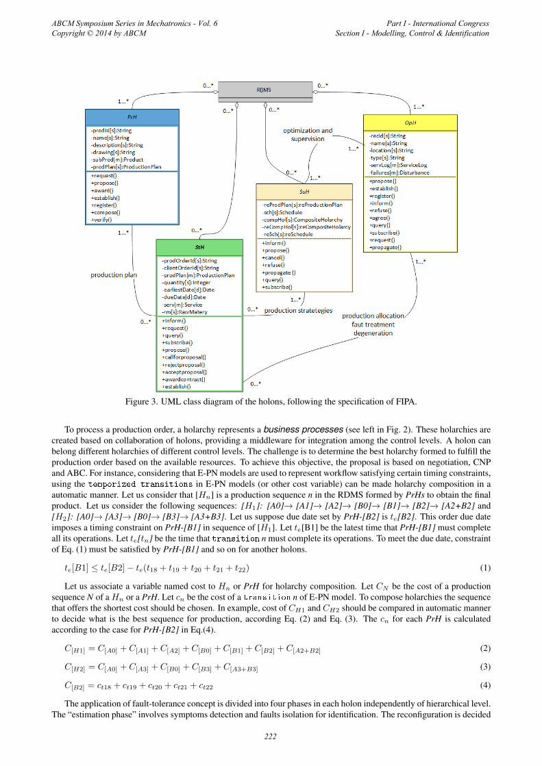
Figure 3. UML class diagram of the holons, following the specification of FIPA.
To process a production order, a holarchy represents a business processes (see left in Fig. 2). These holarchies arecreated based on collaboration of holons, providing a middleware for integration among the control levels. A holon canbelong different holarchies of different control levels. The challenge is to determine the best holarchy formed to fulfill theproduction order based on the available resources. To achieve this objective, the proposal is based on negotiation, CNPand ABC. For instance, considering that E-PN models are used to represent workflow satisfying certain timing constraints,using the temporized transitions in E-PN models (or other cost variable) can be made holarchy composition in aautomatic manner. Let us consider that [Hn] is a production sequence n in the RDMS formed by PrHs to obtain the finalproduct. Let us consider the following sequences: [H1]: [A0]→ [A1]→ [A2]→ [B0]→ [B1]→ [B2]→ [A2+B2] and[H2]: [A0]→ [A3]→ [B0]→ [B3]→ [A3+B3]. Let us suppose due date set by PrH-[B2] is te[B2]. This order due dateimposes a timing constraint on PrH-[B1] in sequence of [H1]. Let te[B1] be the latest time that PrH-[B1] must completeall its operations. Let te[tn] be the time that transition n must complete its operations. To meet the due date, constraintof Eq. (1) must be satisfied by PrH-[B1] and so on for another holons.
te[B1] ≤ te[B2]− te(t18 + t19 + t20 + t21 + t22) (1)
Let us associate a variable named cost to Hn or PrH for holarchy composition. Let CN be the cost of a productionsequence N of a Hn or a PrH. Let cn be the cost of a transition n of E-PN model. To compose holarchies the sequencethat offers the shortest cost should be chosen. In example, cost of CH1 and CH2 should be compared in automatic mannerto decide what is the best sequence for production, according Eq. (2) and Eq. (3). The cn for each PrH is calculatedaccording to the case for PrH-[B2] in Eq.(4).
C[H1] = C[A0] + C[A1] + C[A2] + C[B0] + C[B1] + C[B2] + C[A2+B2] (2)
C[H2] = C[A0] + C[A3] + C[B0] + C[B3] + C[A3+B3] (3)
C[B2] = ct18 + ct19 + ct20 + ct21 + ct22 (4)
The application of fault-tolerance concept is divided into four phases in each holon independently of hierarchical level.The “estimation phase” involves symptoms detection and faults isolation for identification. The reconfiguration is decided
ABCM Symposium Series in Mechatronics - Vol. 6 Copyright © 2014 by ABCM
Part I - International Congress Section I - Modelling, Control & Identification
222

Figure 4. Estimation of the reconfiguration time
Table 1. Negotiation of control system for RDMS based on CNP, adapted from Smith (1980) .
in “planning phase”, which is based on predefined priorities and on historical data, such as statistical significance eachtype of fault in terms of frequency rate, recovery time, and operational cost. The “execution phase” involves sendingcommands for the execution of the selected action plan. The last is “learning phase”, which involves the storage relevantdata to be used in further cases. Therefore, this control system acts according to the following rules:
• if <symptoms> then <selects fault>;
• if <selected fault> then <selects action>;
• if <selected action> then <activates reconfiguration>; and
• if<executed reconfiguration> then <store relevant data>.
In fault occurrence, the holons propagate messages to ensure agile response to faults. The holon that detected fault sendsthis information to SuH starting the propagation of messages and indicating the need for reorganization. StHs receive thismessage propagating to neighboring holons. To prevent accidents, a degeneration holarchy (as illustrated in the right ofFig. 2) can be formed allowing quicker reaction if the fault treatment does not solve the problem.
Figure 4 illustrates how to estimate reconfiguration time. If the resource affected by fault becomes unavailable for longperiod, OpH estimates the recovery time (tr), checks planned orders during this period and cancels current allocation theseorders notifying StH. For this, OpH estimates two different parameters: te, time that the order return to StH; and tc, timeto check if the fault was recovered, re–estimate and re–apply time parameters, if the fault was not recovered as expected.To calculate these two values, tr is determined based on spent in the previous treatment faults and on this time, 50% fortc and 90% for te are increased. If the fault is not recovered, time parameters are re-estimated and planned orders for thisnew time interval (obtained by tc+ te) are canceled . During time that the resource is unavailable, OpH only receives newcommands if they can be run outside estimated range for recovery time.
The negotiation mechanism is based on Contract Net Protocol (CNP) (Smith, 1980) and Activity-Based Costing (ABC)(Cooper, 1988). These rules allow negotiation among holons based on credits (rewards) and fee (penalties) depending ifwork order is completed in due time or not. When StH is responsible for implementing a particular strategy, it receives thefollowing information of PrH: chosen strategy; quantitative measure named “order production fund” (π); scheduled time;penalty for delay (ϕ); and reward value (ε) to be finalized successfully. The StH should manage negotiation to OpHs forachieving goal without exceeding the service fund; and in resource allocation, regarding the performance of them givenby µ. Table 1 summarizes the evolution of this mechanism.
ABCM Symposium Series in Mechatronics - Vol. 6 Copyright © 2014 by ABCM
Part I - International Congress Section I - Modelling, Control & Identification
223

Figure 5. Schema of the method to design control system for RDMS, using PFS and UML techniques.
The “diagnoser” and the “decider” fulfill requirements of fault-tolerant control for diagnosis and decision phases. Thesteps to design these E-PN models are:
• construction E-PN models for control objects;
• construction of E-PN models for control strategies;
• definition of observable events, generally those related to control strategy commands; and non-observable events,generally related to faults – see Sampath et al. (1996);
• construction of E-PN models of sensors;
• initiating construction of “diagnoser” from initial state considered “normal” (without faults);
• relating, by means of transitions and enabling arcs, performed strategies to possible observable and non-observable events which may happen from initial state; and
• relating states obtained to states of sensors. If “diagnoser” does not indicate correct state then possible faults’ causesmust be inferred to solve possible conflicts. This decision mechanism is called “decider” and its decision makingrules may be based on probabilistic data, for example.
3. CONTROL ARCHITECTURE DESIGN FOR RDMS
This Section presents models of the method since initial conception until operation phase of the proposed controlarchitecture (Fig. 5). Each phase involves actors1, the utilized and generated artifacts which are detailed as follows.The phase 5 – integration – ensures a closed-loop to manage the re-designing of the other phases. In the followingexplanation, an application example of benchmark RDMS, illustrated in Fig. 6, is also presented. As cited, this paperfocus on description control architecture and modeling fault-tolerant mechanisms and their application aspects, for detailabout the method see da Silva et al. (2014b,a).
In conceptual modeling phase, specifications are defined: aim of the system, control object, control devices, definitionof tasks, strategies and control functions, description of interaction among parts of the system, and cases of reconfigura-tion. The benchmark RDMS is composed by six workstations WSs that represent autonomous subsystems: distributingworkstation (D −WS), testing workstation (Te −WS), transporting workstation (Tr −WS), handling workstation(H −WS), assembly workstation (A−WS) and robot workstation (R−WS). Work orders (wos) can be executed oneach WS which has its respective controller and operates independently as a stand-alone industrial plant. Each controller
1Terms related to SOA technique are underlined.
ABCM Symposium Series in Mechatronics - Vol. 6 Copyright © 2014 by ABCM
Part I - International Congress Section I - Modelling, Control & Identification
224

Figure 6. Benchmark reconfigurable and distributed manufacturing system.
Table 2. Devices and their functions list of D−WS, which are identified according to DIN/ISO 1219-2:1996-11 and IEC61346-2:2000-12. For example, in the nomenclature “1S2”: 1 =circuit number, S =device code, and 2 =device number.
is connected to the internet allowing operators and clients interact. The aim of benchmark RDMS is automatically assem-bling products composed of workpieces (wps): a cylinder body (black [bcb], red [rcb] or aluminum [acb]), a piston (black[bp] or aluminum [ap]), a spring [s] and a cover [co]. The aluminum piston is assembled only on black cylinder bodywhile black piston is assembled on red or aluminum cylinder bodies. Springs and covers are the same in all assemblies.Furthermore, final products are: [bcb + ap + s + co]; [rcb + bp + s + co]; and [acb + bp + s + co]. Each workstationprocesses the wps at each time, and has buffers with limited storage capacity, besides another resources. Control devices,their control functions, commands and signals for actuation and detection should be identified. The identification is madeaccording to DIN/ISO 1219-2:1996-11 (DIN – Deutsches Institut für Normung)/(ISO – International Organization forStandardization) and IEC 61346-2:2000-12. Table 2 shows the proper primitives to perform the control task for D−WS.
Recursive structure (holons made up of holons) allows designing each holon to figure out the advantages of decom-posing it into a new holarchy. This process is repeated until every holon is completely defined and there is no need forfurther decompositions. Holonic processes are production workflow created dynamically and based on the collaborationof the holons. Each PrH represents a product and has an internal process flow, the required input types and output types.There are the intermediate PrHs: [bcb], [rcb], [acb], [ap], [bp], [s], [co], [bcb + ap], [rcb + bp], [acb + bp], [bcb + ap + s],[acb + bp + s], [rcb + bp + s] and there are three final PrHs: [bcb + ap + s + co], [rcb + bp + s + co] and [acb + bp + s + co].
The synchronization of E-PN models is made by enabling arcs and inhibitor arcs. The following interactiveprocesses are considered in the modeling: request products, implementation services, fault treatment and reconfiguration.These processes are described using UML diagrams (Booch et al., 2005) and the proposed CNP protocol, following thespecifications of FIPA for HMAS.
In dynamic modeling phase, the PN models are created based on preview specifications. Figure 7 illustrates modelingexamples: Fig. 7a shows models of product order for a cylinder body workpiece and following sub-models: PFS of the
ABCM Symposium Series in Mechatronics - Vol. 6 Copyright © 2014 by ABCM
Part I - International Congress Section I - Modelling, Control & Identification
225

(a) Plan production wp[cb] and control objects models (b) Fault treatment and degeneration modelsFigure 7. Examples of modeling
production plan, E-PN of [executesOp_WS] of robot and its controller. E-PN models consider influence of transmissionof control signals and the faults states. Figure 7b presents examples for fault treatment and degeneration.
Figure 8a illustrates PFS of global production process, representing the combination of intermediates PrHs to get finalPrHs, and the required input types and output types among them. To model workflow of a PrH, a place represents a statewhile a transition represents an event or operation that brings the flow from one state to other. Figure 8b exemplifiesthis flow for a PrH.
Figure 9 represents the E-PN and the list of conditions (places) and actions (transitions) to the control process ofD −WS .
Figure 10 shows valve 1 component commanded by OpH, PFS and E-PN models of valve 1 model considering theinfluence of the control signal transmission network, diagnoser for valve 1, flowmeter, and the related decider device.
Analysis of the structure and the dynamic behavior are based on E-PN properties. Qualitative analysis is based onstructural analysis of the E-PN models. Quantitative analysis is performed through simulation of E-PN with timed
transitions. This analysis uses PIPE software (Bonet et al., 2007) and allows re-designing and re-engineering controlsystem during design phase. Scenarios are also identified and models are built for each case. These models must meet therestrictions and achieve the objectives outlined in the hypothesis. Furthermore, they revise the control system models and
(a) Global production (b) Workflow process of a PrHFigure 8. Production process
ABCM Symposium Series in Mechatronics - Vol. 6 Copyright © 2014 by ABCM
Part I - International Congress Section I - Modelling, Control & Identification
226
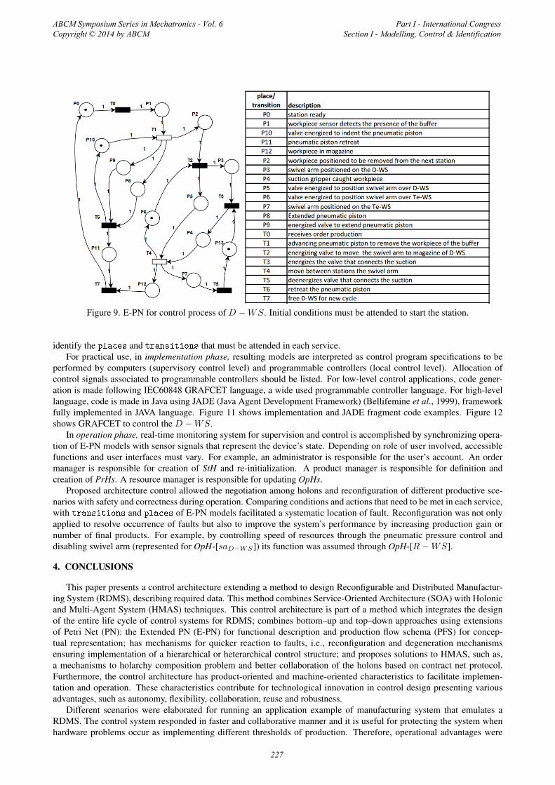
Figure 9. E-PN for control process of D −WS. Initial conditions must be attended to start the station.
identify the places and transitions that must be attended in each service.For practical use, in implementation phase, resulting models are interpreted as control program specifications to be
performed by computers (supervisory control level) and programmable controllers (local control level). Allocation ofcontrol signals associated to programmable controllers should be listed. For low-level control applications, code gener-ation is made following IEC60848 GRAFCET language, a wide used programmable controller language. For high-levellanguage, code is made in Java using JADE (Java Agent Development Framework) (Bellifemine et al., 1999), frameworkfully implemented in JAVA language. Figure 11 shows implementation and JADE fragment code examples. Figure 12shows GRAFCET to control the D −WS.
In operation phase, real-time monitoring system for supervision and control is accomplished by synchronizing opera-tion of E-PN models with sensor signals that represent the device’s state. Depending on role of user involved, accessiblefunctions and user interfaces must vary. For example, an administrator is responsible for the user’s account. An ordermanager is responsible for creation of StH and re-initialization. A product manager is responsible for definition andcreation of PrHs. A resource manager is responsible for updating OpHs.
Proposed architecture control allowed the negotiation among holons and reconfiguration of different productive sce-narios with safety and correctness during operation. Comparing conditions and actions that need to be met in each service,with transitions and places of E-PN models facilitated a systematic location of fault. Reconfiguration was not onlyapplied to resolve occurrence of faults but also to improve the system’s performance by increasing production gain ornumber of final products. For example, by controlling speed of resources through the pneumatic pressure control anddisabling swivel arm (represented for OpH-[saD−WS]) its function was assumed through OpH-[R−WS].
4. CONCLUSIONS
This paper presents a control architecture extending a method to design Reconfigurable and Distributed Manufactur-ing System (RDMS), describing required data. This method combines Service-Oriented Architecture (SOA) with Holonicand Multi-Agent System (HMAS) techniques. This control architecture is part of a method which integrates the designof the entire life cycle of control systems for RDMS; combines bottom–up and top–down approaches using extensionsof Petri Net (PN): the Extended PN (E-PN) for functional description and production flow schema (PFS) for concep-tual representation; has mechanisms for quicker reaction to faults, i.e., reconfiguration and degeneration mechanismsensuring implementation of a hierarchical or heterarchical control structure; and proposes solutions to HMAS, such as,a mechanisms to holarchy composition problem and better collaboration of the holons based on contract net protocol.Furthermore, the control architecture has product-oriented and machine-oriented characteristics to facilitate implemen-tation and operation. These characteristics contribute for technological innovation in control design presenting variousadvantages, such as autonomy, flexibility, collaboration, reuse and robustness.
Different scenarios were elaborated for running an application example of manufacturing system that emulates aRDMS. The control system responded in faster and collaborative manner and it is useful for protecting the system whenhardware problems occur as implementing different thresholds of production. Therefore, operational advantages were
ABCM Symposium Series in Mechatronics - Vol. 6 Copyright © 2014 by ABCM
Part I - International Congress Section I - Modelling, Control & Identification
227
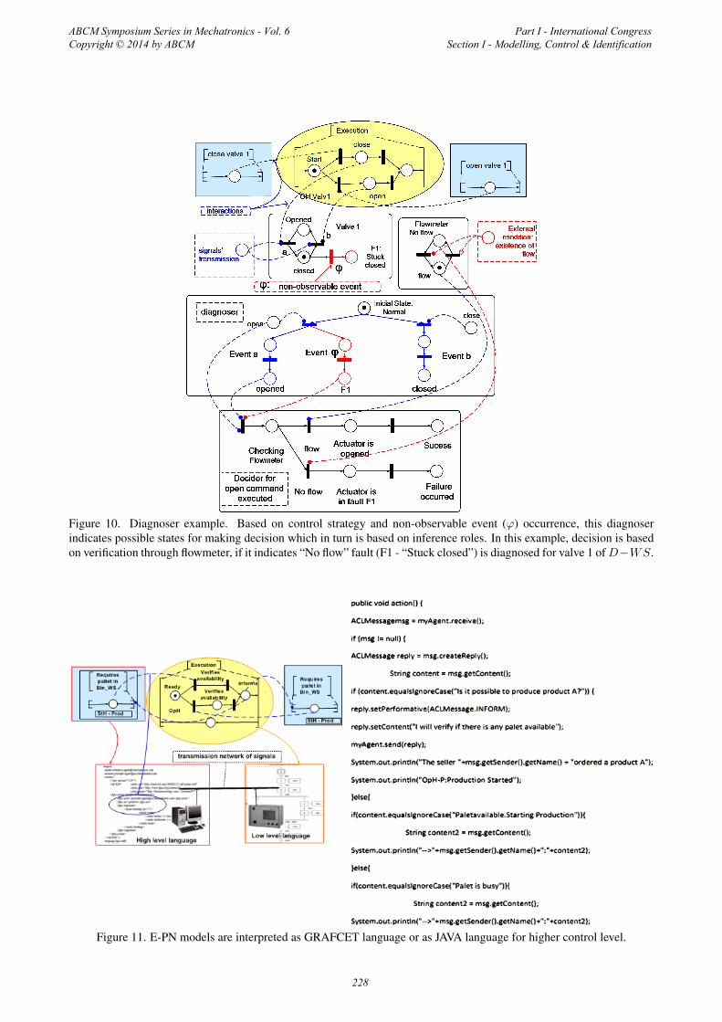
Figure 10. Diagnoser example. Based on control strategy and non-observable event (ϕ) occurrence, this diagnoserindicates possible states for making decision which in turn is based on inference roles. In this example, decision is basedon verification through flowmeter, if it indicates “No flow” fault (F1 - “Stuck closed”) is diagnosed for valve 1 ofD−WS.
Figure 11. E-PN models are interpreted as GRAFCET language or as JAVA language for higher control level.
ABCM Symposium Series in Mechatronics - Vol. 6 Copyright © 2014 by ABCM
Part I - International Congress Section I - Modelling, Control & Identification
228

Figure 12. GRAFCET to controlD−WS. Petri net models facilitate implementation because are similar to this language.
demonstrated such as, better and more efficient use of manufacturing resources, speed of production and ability to deliverproducts faster. As demonstrated in Silva et al. (2012a,b) the method and its control mechanisms and concepts can betailored for other productive systems.
5. ACKNOWLEDGMENTS
The authors would like to thank the partial financial support of the governmental agencies: CNPq, CAPES, FAPESP.
6. REFERENCES
Ali, S.A., Seifoddini, H. and Sun, H., 2005. “Intelligent modeling and simulation of flexible assembly systems”. InProceedings of the 37th conference on Winter simulation. Winter Simulation Conference, pp. 1350–1358.
Bellifemine, F., Poggi, A. and Rimassa, G., 1999. “JADE–A FIPA-compliant agent framework”. In Proc. of PAAM4th International Conference on Practical Application of Intelligent Agents and Multi-Agent Technology. Vol. 99, pp.97–108.
Bonet, P., Lladó, C.M., Puijaner, R. and Knottenbelt, W.J., 2007. “Pipe v2. 5: A petri net tool for performance modelling”.In Proc. of CLEI 23rd Latin American Conference on Informatics.
Booch, G., Rumbaugh, J. and Jacobson, I., 2005. Unified Modeling Language User Guide. Addison-Wesley.Colombo, A.W., Neubert, R. and Schoop, R., 2001. “A solution to holonic control systems”. In In: Proc. of ETFA 8th
IEEE InternationalConference on Emerging Technologies and Factory Automation. Vol. 2, pp. 489–498.Cooper, R., 1988. “The rise of activity-based costing. part one: what is an activity-based cost system?” Journal of Cost
Management, Vol. 2, No. 2, pp. 45–54.da Silva, R.M., Blos, M.F., Junqueira, F., Santos Filho, D.J. and Miyagi, P.E., 2014a. “A service-oriented and holonic
ABCM Symposium Series in Mechatronics - Vol. 6 Copyright © 2014 by ABCM
Part I - International Congress Section I - Modelling, Control & Identification
229

control architecture to the reconfiguration of dispersed manufacturing systems”. In Technological Innovation for Col-lective Awareness Systems, Springer Berlin Heidelberg, Vol. 423 of IFIP Advances in Information and CommunicationTechnology, pp. 111–118.
da Silva, R.M., Junqueira, F., dos Santos Filho, D.J. and Miyagi, P.E., 2014b. “A method to design a manufacturingcontrol system considering flexible reconfiguration”. In Industrial Informatics (INDIN), 2014 12th IEEE InternationalConference on. pp. 82–87. doi:10.1109/INDIN.2014.6945488.
David, R. and Alla, H., 1994. “Petri nets for modeling of dynamic systems: a survey”. Automatica, Vol. 30, No. 2, pp.175–202. doi:10.1016/0005-1098(94)90024-8.
Ferber, J., 1999. Multi-agent systems: an introduction to distributed artificial intelligence. Addison-Wesley LongmanPublishing Co., Inc.
FIPA, A., 2002. “Foundation for intelligent physical agents”. http://www.fipa.org.Garcia Melo, J.I., Junqueira, F., Morales, R.A. and Miyagi, P.E., 2008. “A procedure for modeling and analysis of service-
oriented and distributed productive systems”. In International Conference on Automation Science and Engineering.IEEE, Washington, pp. 941–946. doi:10.1109/COASE.2008.4626561.
Groba, C., Braun, I., Springer, T. and Wollschlaeger, M., 2008. “A service-oriented approach for increasing flexibil-ity in manufacturing”. In International Workshop on Factory Communication Systems. IEEE, pp. 415 –422. doi:10.1109/WFCS.2008.4638735.
Han, R., Liu, K., Ju, Y. and Zhao, J., 2008. “A Petri net theory-based method for modeling web service-based sys-tems”. In International Conference on Wireless Communications, Networking and Mobile Computing. pp. 1–7. doi:10.1109/WiCom.2008.2839.
Koestler, A., 1968. “The ghost in the machine.”Mehrabi, M.G., Ulsoy, A.G. and Koren, Y., 2000. “Reconfigurable manufacturing systems and their enabling technolo-
gies”. International Journal of Manufacturing Technology and Management, Vol. 1, No. 1, pp. 114–131.Mendes, J.M., Leitão, P., Restivo, F. and Colombo, A.W., 2009. “Service-oriented agents for collaborative industrial
automation and production systems”. In Holonic and Multi-agent Systems for Manufacturing, Springer, pp. 13–24.Miyagi, P.E., Hasegawa, K. and Takahashi, K., 1988. “A programming language for discrete event production systems
based on production flow schema and mark flow graph”. Trans. of the Society of Intrument and Control Engineers(SICE Japan), Vol. 24, No. 2, February, pp. 77–84.
Murata, T., 1989. “Petri nets: Properties, analysis and applications”. Proceedings of IEEE, Vol. 77, No. 4, pp. 541–580.Nagorny, K., Colombo, A.W. and Schmidtmann, U., 2012. “A service-and multi-agent-oriented manufacturing automation
architecture: An IEC 62264 level 2 compliant implementation”. Computers in Industry.Sampath, M., Sengupta, R., Lafortune, S., Sinnamohideen, K. and Teneketzis, D.C., 1996. “Failure diagnosis using
discrete-event models”. Control Systems Technology, IEEE Transactions on, Vol. 4, No. 2, pp. 105–124.Silva, R.M., Arakaki, J., Junqueira, F., Santos Filho, D.J. and Miyagi, P.E., 2012a. “Modeling of active holonic control
systems for intelligent buildings”. Automation in Construction, Vol. 25, pp. 20–33.Silva, R.M., Arakaki, J., Junqueira, F., Santos Filho, D.J. and Miyagi, P.E., 2012b. “A procedure for modeling of holonic
control systems for intelligent building (HCS-IB)”. Advanced Materials Research, Vol. 383, pp. 2318–2326.Silva, R.M., Miyagi, P.E. and Santos Filho, D.J., 2011. “Design of active holonic fault-tolerant control systems”. Springer
IFIP Advances in Information and Communication Technology, Vol. 349, pp. 367–374.Silva, R.M., Junqueira, F., dos Santos Filho, D.J. and Miyagi, P.E., 2012c. “Design of reconfigurable and collaborative
control system for productive systems”. ABCM Symposium Series in Mechatronics. 1ed.Rio de Janeiro, RJ, Vol. 5, pp.813–822.
Smith, R., 1980. “The contract net protocol: High-level communication and control in a distributed problem solver”.IEEE Transactions on Computers, Vol. 100, No. 12, pp. 1104–1113.
Tommila, T., Hirvonen, J., Jaakkola, L., Peltoniemi, J., Peltola, J., Sierla, S. and Koskinen, K., 2005. “Next generationof industrial automation concepts and architecture of a component-based control system”. VTT Tiedotteita. ResearchNotes, Vol. 2303.
Vrba, P., Tichý, P., Marík, V., Hall, K.H., Staron, R.J., Maturana, F.P. and Kadera, P., 2011. “Rockwell automation’sholonic and multiagent control systems compendium”. Systems, Man, and Cybernetics, Part C: Applications andReviews, IEEE Transactions on, Vol. 41, No. 1, pp. 14–30.
Zhang, Y. and Jiang, J., 2008. “Bibliographical review on reconfigurable fault-tolerant control systems”. Annual Reviewsin Control, Vol. 32, No. 2, pp. 229–252.
7. RESPONSIBILITY NOTICE
The authors are the only responsible for the printed material included in this paper.
ABCM Symposium Series in Mechatronics - Vol. 6 Copyright © 2014 by ABCM
Part I - International Congress Section I - Modelling, Control & Identification
230