
Control Activities and Interests M.Jonker. CV 75: Cern (summer student) –drift-chambers (i.e....
38
Control Activities and Interests M.Jonker
-
Upload
tristan-grimmer -
Category
Documents
-
view
219 -
download
0
Transcript of Control Activities and Interests M.Jonker. CV 75: Cern (summer student) –drift-chambers (i.e....

Control Activities and Interests
M.Jonker

CV• 75: Cern (summer student)
– drift-chambers (i.e. particle detector) tests
• 76: UvA/Cern (‘diploma work for IT-option’)– Development of detector readout electronics. (4 ns precision hit recording system)
• 77-82: Charm neutrino experiment (PhD student)– DAQ system, physics analysis, thesis.
• 83-86: SLAC ASP experiment (Post-Doc)– Detector building, Readout Electronics, DAQ and monitoring, physics analysis.
• 86-93: Delphi (Fellow / Staff)– DAQ, monitoring, control.
• 93-99: SL/OP EIC– LEP and SPS operations + control software, timing, RSO
• 99- ?: SL/CO– SPS2001, …

Current Activities & Interests
• SPS2001 related– Architecture
– Parameter Maintenance
– Contracts
– Device Server Contract Support
• Rocs/mugef – BT device servers• Timing• SPS interlock• RT feedback

SPS2001 Project
Objectives:Design and implement the operational software to run the SPS in
the LHC era
Most important: deal with multi cycling environment.
It is not:– just a matter of cycle scheduling (aka timing).
If it were, it it would have been solved already a long time ago.
– rewriting the actual SPS software with the latest software technologies.

SPS2001 ProjectMajor problems:
- Management of multiple resident cycles in the equipment- … and in the application layer- Parameter maintenance that is capable to manage multiple instances of the same
cycle but with different settings.- Protection system (interlock) that is cycle aware.- Provide input for an efficient scheduling of the CERN accelerator complex
(CBCM).- Unify three underlying control systems (sps, orbit, tz)- Eradicate c-tree database- Base control system on subscription not on polling (eradicate sl-equip)
In the implementation aim for a maximum of reusability, and homogeneity, reduce inter-component coupling
Build the control system up out of generic components.

SPS2001 Architecture
SPS Equipment domains
SPS2001 compliantdevice
SPS2001 compliantdevice
SPS2001 compliantdeviceSPS2001 compliant
deviceSPS2001 compliantdevice
SPS2001 compliantdeviceSPS2001 compliant
deviceSPS2001 compliantdevice
SPS2001 compliantdevice SPS2001 compliant
device
Equipment to logical entity mapping layer.
Logical State Devices
Measurement Device ManagerLogical State
Devices
Logical State Device
Cycle Configuration Manager Parameter Loader
Measurement Device Manager
Cycle generation dom
ains
Beam Process Model &Setting Generator
Machine EquipmentModel
Optim
isation and surveillance domains
Feed Forward andcorrections
Fixed Display generator
Data logging
External dom
ains
Central Alarm System
Central Beam andCycle Manager
Legacy Software
Interactive Applications
Operator WorkContext
Parameter EditingTools
InteractiveOptimisationTools.
Generic equipmentdiagnostics
Cycle ExploitationApplications
Standard ParameterDisplay
Exploitation dom
ains
User Request Handler
Interlock Handler
Local Beam and CycleManager
Exploitation
Cycle and SequenceManager
Beam process, Cycle andSequence Repository
Param
eter maintenance dom
ains
Trim Manager
Parameter Manager andTranslator
Parameter Repositoryand Version Manager
Exploitation domain:
• Optimises SPS cycle usage
• Handles user requests
• Responds to interlock conditions
• Machine Access
Parameter Maintenance Domain:
• Trim Server
• Settings translation
• Trim propagation
Beam optimization domain
• Correction procedures
• Surveillance
• Logging and reporting

PC Ref: IQ.f1, IQ.f2, IQ.d
Beam ParametersNon correctable
Operator
Expert
Equipment ParametersNon correctable
Operator
Expert
HWSend to HW
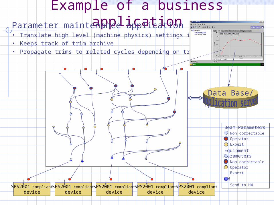
Example of a business application
Tune matix
Strength: KQ.f1, KQ.f2
Q.ph62 (Phase.h 6-2)
Energy
Q.h, Q.v
PC Transfer Function: Vref(I)
Magnet Currents IQ.f1, IQ.f2, IQ.d
GQ.f1, GQ.f2, GQ.d
Equipm
ent m
odelB
eam m
odel
Strength: KQ.f, KQ.d
Calibration: I(G)
… a minor detail of the overall SPS parameter model:
Beam ParametersNon correctable
Operator
Expert
Equipment ParametersNon correctable
Operator
Expert
HWSend to HW
Example of a business applicationParameter maintenance application• Translate high level (machine physics) settings into device settings
• Keeps track of trim archive
• Propagate trims to related cycles depending on trim context
SPS2001 compliant
deviceSPS2001 compliant
deviceSPS2001 compliant
deviceSPS2001 compliant
deviceSPS2001 compliant
device
Data Base/

What and Why of Device Contracts ?
Accelerator equipment is composed of a large variety of different types such as:– Magnets, RF, Kickers, Beam-obstacles, Beam-observation
The control of this equipment deals with various aspects such as:– State Control– Setting Management– Measurements– Cycle Organisation– Expert Settings and Options– Diagnostics and Reporting– etc
The Device Contracts provides the framework to provide a homogeneous view of a heterogeneous set of devices.

Device modelOne could be tempted to arrange accelerator control equipment into
a hierarchical class model (i.e. based on single inheritance).
AcceleratorDevice
ObservationDevice
ControlDevice
Orbit
Tune
Etc
Cycle Oriented ControlDevice
NonCycling ControlDevice
VacuumStopper
Kicker
RF
Magnet
Extraction
Correctors
Quads
MAIN Magnets
However,
this organization does not reflect th
e
usage pattern by the business
applications.

Multiple inheritanceIt is more appropriate for Accelerator control equipment inherit from one or more
“super-classes” that represent general control aspects:
RFOrbit
Kicker Stopper
VacuumTune MagnetsMagnets
The applications only care about these type of devices.
StateDevice
SettingDevice
MeasurementDevice
CycleOrientedDevice
…
Every such “general control aspect” is represented by a specific device contract.
An accelerator device implements the contracts that are required for its functionality.

Why contracts ?Contracts is NOT middleware, it is based on middleware:
• Standardisation on communication and a get-/set- “property” device model (aka middleware) is not enough.
• Need to define the semantics (I.e. which device properties are used, how these properties are expected to behave).This should not be left to the individual equipment groups:– The SPS equipment has a heterogynous interface and semantics. This has
led to the need of black boxes (I.e. equipment specific driver routines), which provided some level of homogenisation of the equipment to the application layer.
Contracts lay down the semantics of the device property model used by the SPS2001 applications. They avoid the need for black boxes (which makes the applications much simpler).
What do the SPS2001 contracts provide ?
In general:• Definition of group of logical functionality with a protocol for
information exchange.• Support data subscription.• Provide methods to obtain device and data description from the
severs.
Advantages• No need to know the equipment type, equipment self-description
is part of the contract. Examples:– BT, PC, RF & BI equipment, can all use the same interface for loading
cycle settings– Virtual devices can be build from physical devices easily (simple recipes
because all equipment is access identically)
Note: Contracts are used by logical equipment as well.

Example: Device Contracts Usage
Physical device
PC
Physical device
Kicker
Physical device
PC
Physical device
Stopper
Physical device
You name it
MCSM-Control
SPS2001 applicationMCSM
Logical device
SPS_ring
Logical device
TT10_proton
SPS_ring:State Operational• Stopper out, QF1 on, etcState Beam Safe• QF1 on, etcState Shutdown• etc
Note that these logical devices act in two directions:
• Commands propagate down
• Status propagate up

Example: Device Contracts Usage
Physical device
PC
Physical device
Kicker
Physical device
PC
Physical device
Stopper
Physical device
You name it
SPS2001 application
Setting Management
Logical device Settings Repository
• In sending a setting to the hardware we do not have to understand the contents of the settings.
• We have to care about coherence of a setting update: data acceptance check HW commit

Contracts overview
• Identification (mandatory for all devices)– Identifies a particular device– Identifies the implemented contracts of the device and other device constants.– Identifies associated devices (used in tree browsers)
• StateManagement– Request state change (reply through transaction and/or state change)– Subscribe state changes– Get state– Get detailed state (subcomponents state)– Get State Model (both main state and subcomponents state)
– The state model defines which states are possible and which states can be requested. They also define the mapping between a binary format and a user readable format.

Contracts overview
Data Catalogue contractsA data catalogue provides a list of properties published by a device
• Can get/set/subscribe to these properties
• Can obtain a data description of these device properties
• DeviceData (intended usage: cycle independent expert parameters)– Read/write– Restricted access (through the security contract)
• SettingData (intended usage: operational settings)– Read/write/subscribe– Cycle aware (i.e. data is specific for a given cycle)– Transaction handling including commit (through a timing message).
• MeasurementData– Read/write-filter/subscribe– Cycle aware– Data may be filtered on a per user defined criteria

Contracts overview
Others• CycleManagement (cycle space management of cycle oriented equipment)
• Expert
• Security
• Transaction Management
• Diagnostic
• Logging and Alarms
• Configuration

DataCatalogues in more detail
• A data catalogue provides a list of DataEntries with their format descriptions. Example:
• GefFunction: a table of undefined depth with a time and a value column.
• DataCatalogue Entries are described in XML format:Example:
<table id="EPD" format="long" depth="4" > <comment text="EPD module parameters of the kicker system." /> <permission expert="RWC" control="R" operator="R" public="R" /> <column name="EPDIndex" accessibility="None" minimum="1" maximum="4" /> <column name="RequestedStatus" accessibility="RW" minimum="0" maximum="1" /> <column name="ActualStatus" accessibility="R" minimum="0" maximum="1" /> <column name="RequestedDelay" accessibility="RW" unit="seconds" scale="-6“
precision="1000" minimum="0" maximum="2000000" /> <column name="ActualDelay" accessibility="R" unit="seconds" scale="-6“
precision="1000" minimum="0" maximum="2000000" /></table>

DataCatalogues in more detail
This XML description is used to:– generate C structures and wrapper code (to enforce
strong typing) that can be used by the device server.– java meta data for creating jtable model
+ in the future:
– generate data validation functions (for the device servers)
– generate device specific java wrapper classes based on generic DataContainer classes.
– generate database mappings (to archive any device data on database tables)
– Assist in generic filtering
<table id="EPD" format="long" depth="4" > <comment text="EPD module parameters of the kicker system." /> <permission expert="RWC" control="R" operator="R" public="R" /> <column name="EPDIndex" accessibility="None" minimum="1" maximum="4" /> <column name="RequestedStatus" accessibility="RW" minimum="0" maximum="1" /> <column name="ActualStatus" accessibility="R" minimum="0" maximum="1" /> <column name="RequestedDelay" accessibility="RW" unit="seconds" scale="-6“
precision="1000" minimum="0" maximum="2000000" /> <column name="ActualDelay" accessibility="R" unit="seconds" scale="-6“
precision="1000" minimum="0" maximum="2000000" /></table>

XML based data descriptionReminder: XML is used to describe the data entry points (properties) format, not
to encode the data itself.
Advantages of XML data description:• Format is independent of a database.
However, mapping between an XML-based data description and a database resident data description is possible. (I.e. one does not exclude the other)
• There is never a mismatch between the device server and its data description.
• Simple device explorers can be used to discover the data (no need for database connections).
• XML is source code and can be subjected to version management.

XML Parsing how it works• XML provides an excellent syntax for defining
configuration information.• Using SAX parsers (Simple Api for Xml) the contents
of an xml text can be decoded and stored in an object:
XML:<table name=data depth=4> <comment>a table</comment> <column name=injection/> <column name=volt/> <column name=length/></table>
class TableString name;String comment;Column[] theColumns;
class ColumnString name;
Sax parsing:

XML Parsing: the schema
In the example of previous slide, the definition of the class have to match the syntax of the xml. To enforce that an xml text obeys the syntax we can define a schema. (Today a proper schema language itself is based on XML)
XML:<table name=data depth=4> <comment>a table</comment>
class TableString name;String comment;Column[] theColumns;
class ColumnString name;
Sax parsing(schema):
<schema …> <element name=table> <element name = column /> etc… </element></schema>

XML Parsing: the schema compiler
The schema can be used to enforce that the xml code matches the target class, but it can do more…
It can be used to generate the target class itself, including a constructor that will invoke the sax parser and creates the objects.
XML:<table name=data depth=4> <comment>a table</comment>
class TableString name;String comment;Column[] theColumns;Table(String XML)
class ColumnString name;
Constructor()
<schema …> <element name=table> <element name = column /> etc… </element></schema>
object
object
SchemaCompiler

transaction handlingAn important aspect of setting management in the devices is
transaction handling.(Transaction Handling is a standard feature of the Setting DataCatalogue entries.)
Transaction handing provides coherent setting updates : All settings take effect on the same cycle.
Transaction handing aims at optimizing bulk setting updates (100 - 2000 settings).
The client does not need to wait for the individual replies.
– It is based on asynchronous communication (sends).– The return status is obtained by subscription to the transaction
property (a property shared with all devices in a device server).– The transaction property on the server also keeps track of the
pending update requests and accepts commands to abort or commit the pending requests.

transaction handling
From the client perspective:– Get a transaction object from the device access package.
(Get a hardware commit key and give it to the transaction object.)– Get the cycle identification
These three items form part of the user context which is passed when sending data to the equipment.
– Send data to one or more device, (Note, data is send asynchronously, the completion status will be communicated to the transaction object.)
– Check (and wait) for the completion status of the transaction object. The transaction object can tell which of the equipment failed or rejected the request.
– Either commit or abort the transaction object:• Commit: the transaction uses the HW commit key• Abort: the transaction knows which equipment needs to be informed.

Contracts definition and implementation status
Contract: defined implemented (server C- support)
Identification fullExpert fullStateManagement fullDataCatalogues (3) fullCycle Management rudimentarySecurity noTransaction Management fullDiagnostic - -Logging and Alarms - -Configuration full

Device Server implementationsTo assist equipment groups with a correct implementation of the contracts, the SPS2001 project offers a library with common code.
Example: Resident cycle management, commit handling
The implementation of a device server calls functions of the support library to register properties and to declare set- get- property callbacks. (c version) (or overwrites virtual methods (future c++ version)
a callbacks can:a) do the work themselves directly (i.e. talk directly to the VME devices)b) Use different threads to schedule the real work.c) Communicate with other processes through shared memory and other
mechanisms.
Option a) and b) is used by BT, option b) and c) is used by PO.

Device Server implementations.
Implementation by SPS equipment groups:BT:
– MKP device server in production.– Various other device servers (for beam obstacles) ready for deployment.
PO:– Implementation support provided by me. (manpower shortage in the
equipment group).– Contracts are implemented based on a local SPS2001 server. – Improve some of the the underlying processes of the power converters to
make a local integration of the SPS2001 device server more efficient and effective. (See next slide)
• PowerConveter state status/control• Setting Management
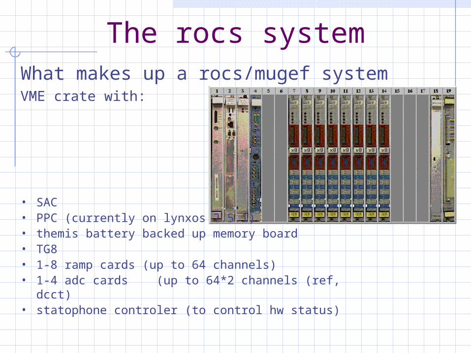
The rocs systemWhat makes up a rocs/mugef systemVME crate with:
• SAC• PPC (currently on lynxos 2.5.1)• themis battery backed up memory board• TG8• 1-8 ramp cards (up to 64 channels)• 1-4 adc cards (up to 64*2 channels (ref, dcct)• statophone controler (to control hw status)

SPS2001 architecture
SPS2001 device server
SPS2001 deviceSPS2001 device
SPS2001 device
SPS2001 device
m3sba3
SPS2001 device server
SPS2001 device
SPS2001 device
SPS2001 device
SPS2001 device
SPS2001 device server
SPS2001 device
SPS2001 device
SPS2001 device
SPS2001 device
mkp
rf
SPS2001 device server
SPS2001 device
SPS2001 device
SPS2001 device
SPS2001 device
SPS2001 device server
SPS2001 device
SPS2001 device
SPS2001 device
SPS2001 device
SPS2001 device server
SPS2001 device
SPS2001 device
SPS2001 device
SPS2001 device
m.sba.
SPS2001 state devices
SPS RINGTT60
TT20
TT10
InterlockAlarm Console Display
measurement devices
SPS RINGTT60
TT20
TT10
Function Loader
SPS RINGTT60
TT20
TT10

ROCS software
Motivation:
The involvement with the rocs/mugef system was motivated by the implementation work of the SPS2001 device server for the PowerConverters.
Some work was started in september 2001 by John Brazier and me.
I took it up again in the beginning of May.

The rocs clientsThe initial SPS2001 server was developed as a
regular EQUIP client. However, as such it was not alone. Other clients are:
• SSIS (poling individual status channels)
• Nodal alarm survey
• TZ survey for pvss/ST
• Steering
• CMW client
This has made some of the bottlenecks apparent.

Rocs architectureor where to hang the SPS2001 server
mhmhmhmh
SL_Equip client
mugef server
rocsfe
sequence
threadthreadthreadthread
timing
acquire
floader
stato
Startup
SPS2001 server
actionactionactionactionaction
SPS2001 clients
statoSurvey
Rocssystem

statoSurvey implementation
statoSurveyance
Survey-Thread
Client- Thread
Statophon HW
PSTAT cacheShared memory(read only for others)
Sequence task SPS2001 server
Anonymous data signal:Signals report number updates to “whom it may concern”

Floader Implementation (in progres)
Based on the same principle components as the statoSurvey process:• Client thread to accept and execute commands (reply is optional)• A high priority thread to respond to timing interrupts• Structured shared memory segments (read only access to outside) with
status information• Anonymous signal mechanism to inform anyone that something has
changed.
More complications:• Manage memory on HW boards• Manage memory of persistent memory boards• Reply to external events• Accept rt-corrections (one more thread)

Floader Implementation (in progres)Implementation in C++
Class to manage shareable memory managed data stores
• position independent memory management tool
Class to manage setting and setting transaction:
• A shareable transaction store
• A shareable persistent setting store
• Multiple shareable hw resident setting stores
• (Allows binding of multiple events to the same setting, special rocs/mugef feature for coast/economy)
These are generic classes which are then specialized into Rocs specific classes.

Floader Implementation
floader
StartFunc-Thread
Client-Thread
Ramp Cards
Setting and transaction cacheShared memory(read only for others)
Sequence task SPS2001 server
Anonymous data signal:Signals report number updates to “whom it may concern”
Timing task(existing)


![· 2018-04-16 · Drift Chambers, Proportional Chambers E B Ring Imageing Cerenkov Counter, TRI), Preshower Detector, Calorimeter B fi 50 Ring Imageing Cerenkov Counter y [cm] 300](https://static.fdocuments.net/doc/165x107/5f9fa151da910861e0246e21/2018-04-16-drift-chambers-proportional-chambers-e-b-ring-imageing-cerenkov-counter.jpg)


