Contract No: PL019864 - Microgridsmicrogrids.eu/documents/661.pdf · transformer stations Wa24,...
36
More Microgrids DF5 1 Advanced Architectures and Control Concepts for MORE MICROGRIDS Contract No: PL019864 WORK PACKAGE F Task F6: Field test on the transfer between interconnected and islanding mode Deliverable DF5: Report on Field Test for the Transfer between Interconnected and Islanding Mode at the Ecological Settlement in Mannheim-Wallstadt (MVV) December 2009 Final Version
Transcript of Contract No: PL019864 - Microgridsmicrogrids.eu/documents/661.pdf · transformer stations Wa24,...
More Microgrids DF5 1
Advanced Architectures and Control Concepts for
MORE MICROGRIDS
Contract No: PL019864
WORK PACKAGE F
Task F6: Field test on the transfer between interconnected and islanding mode
Deliverable DF5: Report on Field Test for the Transfer between Interconnected and Islanding Mode at the Ecological Settlement in Mannheim-Wallstadt (MVV)
December 2009
Final Version

More Microgrids DF5 1
Document Information Title: Advanced Architectures and Control Concepts for MORE MICROGRIDS Date: December 31, 2009 Task(s): TF6: Transfer between interconnected and islanding mode Deliverable DF5: Report on Field Test for the Transfer between Interconnected and Islanding Mode
at the Ecological Settlement in Mannheim-Wallstadt (MVV) Review Britta Buchholz, MVV and José Oyarzabal, Labein - Tecnalía Approver Georges Kariniotakis, Ecole des Mines de Paris Coordination: Roland Pickhan [email protected] Authors: Mariam Khattabi [email protected]
Stefan Drenkard [email protected]
Hans Dietschmann [email protected]
Aris Dimeas [email protected]
Panayiotis Moutis [email protected]
Access: Project Consortium European Commission x PUBLIC
Status: For Information Draft Version Final Version (internal document) Submission for Approval (deliverable) X Final Version (deliverable, approved on. )

More Microgrids DF5 2
Table of Contents 1. Objectives 3 2. Description of the field test Mannheim 4
2.1 Preparation of the grid segment for microgrid operation 4 2.1.1 Awareness building with prosumers 4 2.1.2 Adaptation of grid structure 5 2.1.3 Power quality and grid characteristics 6
2.2 Study of the distribution system 9 2.2.1 Distribution grid 9 2.2.2 System analysis 10
2.3 Generators and loads 13 2.3.1 Loads 14 2.3.2 Generators 16
2.4 Multi agents system in the Mannheim field test 17 2.4.1 Multi-Agent System Structure 19 2.4.2 Jade Platform 21
3. Realized experiments in Mannheim-Wallstadt 22 3.1 Introduction 22 3.2 Transition from grid connected to islanded mode in the Kinderhaus 23 3.3 Test of functionality of the agents 26
3.3.1 Set-up 26 3.3.2 Functionality test 27 3.3.3 Test of the negotiation abilities of the NTUA agents 29
4. Conclusions and future prospects 32 5. References 34 6. Acknowledgements 34

More Microgrids DF5 3
1. Objectives The project More Microgrids intended to investigate, develop and demonstrate the operation, control, protection, safety and telecommunication infrastructure of novel architectures for microgrids and to determine and quantify their economic benefits and operation and control concepts in both stand-alone and interconnected mode on laboratory microgrids. A key feature of a microgrid is its ability to separate and isolate itself from the utility seamlessly with little or no disruption to the loads within the microgrid during a utility grid disturbance. Then, when the utility grid returns to normal, the microgrid automatically resynchronizes and reconnects itself to the grid, in an equally seamless fashion. The microgrid concept seeks to provide this technically challenging functionality without extensive (i.e. expensive) custom engineering. In addition, the design of the microgrid also provides high system reliability and great flexibility in the placement of distributed generation within the microgrid. The microgrid is intended to offer these functionalities at much lower costs than traditional approaches by incorporating peer-to-peer and plug-and-play concepts for each component within the microgrid. In Mannheim, the objective of the task as stated in Annex 1 of the contract has been to aggregate several DG sources and controllable loads to an interconnected micro grid with islanding option within a small grid segment of the Mannheim electricity grid. The first objective was to prepare a suitable grid segment for microgrids operation. The second objective was to show reliable communication with diverse loads and generators. Because the selected test site is no laboratory site but a “regular” segment of the grid, all tests have to comply with the German grid quality standards and regulations. The third objective was to prove seamless transition from grid connected to islanding mode. Challenge has been to assure that the Microgrid central controller recognizes if a grid disconnection is intended and necessary for maintenance or if it is due to blackout. In both cases the Microgrid shall continue the operation in a flawless islanded mode. The fourth objective was to test functionalities and negotiation abilities of the agents developed at NTUA. The control strategy “Multi Agent Systems (MAS)” had been developed in WPB. For safety reasons, a proof of correct communication at the NTUA laboratory test and at the Microgrids test site in Kythnos (TF3) as well as at the MVV laboratory was mandatory prior to the installation in Mann-heim. This report will first describe the technical configuration of the field test Mannheim, and then explain the control strategies for the experiments. The report will further evaluate operation experiences and monitoring results of the field test. Socio-economic and legal aspects are dealt within the experiment “Washing with the sun” as well as in the work packages G and H and have not been reported in this deliverable DF5.

More Microgrids DF5 4
2. Description of the field test Mannheim 2.1 Preparation of the grid segment for microgrid operation 2.1.1 Awareness building with prosumers The selected field test site is an ecologically-oriented residential estate in the district “Wallstadt” of Mannheim, Germany. It is a key success factor to start awareness building with consumers and producers (prosumers) who have a positive attitude towards innovation and renewable energy. The settlement includes 580 households. It represents a typical residential area with an intermeshed ring grid structure which is connected to 3 transformer stations. Regarding distributed generation, the site includes several privately owned small photovoltaic systems and one private Whispergen cogenera-tion unit. Further PV-installations are planned by private persons. One measure for awareness building in preparation of the field test was the customization and installation of the display panel “VisiKid” at the entrance of the Kinderhaus in Mannheim-Wallstadt. VisiKid shows in real time, which power and how much energy is being produced by the PV-Panels. This intuitive explanation brings the timely value of energy from photovoltaic systems closer to parents and children.
Figure 2.1: The VisiKid panel displaying the PV-generation at the entrance of the Kinderhaus To achieve a reduced consumption or load a shift within a demand side management scheme the co-operation from customer’s side needs to be ensured. To study and stimulate customer’s co-operation, the team carried out the activity “Washing with the Sun” in 2006. During a testing period of one month, selected residents of the Mannheim-Wallstadt estate have been given daily recommendations to shift loads to time zones with high local PV generation. They wrote down their individual load shifts of washing machines and tumble dryers, and were provided with electronic meters as technical support for monitoring their reactions. Goal of this activity was to evaluate the ability of the residents to adapt to a side demand management strategy and eventually change their behaviour according to it. The load profiles have then been evaluated, and promising results showed a significant load change. The customers have positively reacted to the instructions and are interested in further experiments in the context of our research projects.

More Microgrids DF5 5
2.1.2 Adaptation of grid structure The LV distribution grid is owned by MVV Energie. It represents a typical residential area with an intermeshed ring grid structure. It is fed from the MV-grid via three 20/0.4 kV, 400 kVA transformers and is operated in closed configuration. The LV grid, whose neutral is directly grounded at the MV/LV substation, is a three-phase network with distributed neutral. The LV voltage is 230 V (phase to neutral voltage) / 400 V (phase to phase voltage) the MV voltage is 20 kV. The apartments are connected to the electrical network by underground cables (Al 4x150mm2). 27 distribution boxes and further underground cables complete the low voltage grid in Wallstadt.
Figure 2.2: Map of the field test site in Mannheim - Wallstadt with 3 MV/LV transformers
(Wa24, Wa25 and Wa26) along Kormoranstrasse The team modified the LV-grid in order to prepare it for optional islanding. Figure 2.3 indicates the new distribution area served by one transformer, e.g. houses in the streets to the left are served by the red distribution sub-grid connected to transformer Wa24 (in the middle at the upper end), while the streets to the right are served through the green sub-grid by transformer Wa21 (in the middle at the right side). Distribution box Wa055 (in the middle near Wa21 where both red and green line meet) allows to connect parts of the red distribution sub-grid to the ‘green’ distribution grid of Wa21 in case of a failure of transformer Wa24. In a real micro-(sub-)grid this will not be necessary as in this case the internal generation possibly together with reduced load will allow to run the grid without external power fed-in.

More Microgrids DF5 6
Figure 2.3: Adapted low voltage network at Mannheim Wallstadt – the sub-grid shown in red is served by transformer WA24 (in the middle at the upper end), the green by Wa21 (right)
2.1.3 Power quality and grid characteristics In terms of power quality there is no call for action at the moment. The short circuit power is rated around 3 MVA or higher. Therefore photovoltaic systems with a capacity < 5 kW can be installed without problems. Within summer time the maximum load at the transformer has been measured to be 150kW which is 37.5% of the transformer capacity. The calculated value is about 240 kVA which would be about 60% of the transformer capacity. Typical for Germany the grid is meshed (i.e. neighbouring transformers are able to partially take over in case of failures) and operated far below maximum capacity offering chances to integrate further distributed generators. This grid segment is suitable for this study: • it can be disconnected from neighbouring transformers • it includes controllable loads and distributed generators • the main aspects of microgrids, such as balancing local generation and consumption can be
studied. As a preparation to the field test, power measurement equipment has been installed in each of the transformer stations Wa24, Wa25 and Wa26: the power analyser UMG 510 of Janitza electronics company (cf. Figure 2.4). The power quality analyzer is equipped with 4 current and voltage inputs and collects and digitizes the effective values (True RMS) from currents and voltages in the 50 Hz networks. The integrated micro-processor calculates the electrical parameters from the sampling values. UMG 510 allows the monitoring of power flows in all 3 phases, plus any voltage differences between neutral and ground. The relevant voltage can be defined as a phase-neutral or a phase-phase voltage for measurement in a three-phase system. This voltage serves the device as a reference voltage for harmonic measure-ment, transient and event recording and for the flicker meter. A nominal current can be set using this for the measurement of electrical current events. All the measurements are delivered according to the

More Microgrids DF5 7
EN 50160. The 4th current and voltage input represents a separate measurement system. However, it is generally used for measuring the current in the neutral or PE conductor or used for measuring a voltage difference between N and PE. This step was foreseen to assure that any experiments involving large scale loads and generators in a given transformer island could be monitored by MVV.
Figure 2.4: Installed UMG 510 power measurement device in the Wa24 Another related step was to allow the forwarding of the measurements to a central data collection point at a MVV location, and to eventually allow a software–based Demand Side Management system to receive grid relevant information. For this purpose a DSL modem has been installed in the Wa24 transformer station with a weekly check of the collected data. The following figure shows the DSL modem in the Wa24 station (cf. Figure 2.5).
Figure 2.5: DSL Modem for forwarding of grid data to a central position To prepare the site for a microgrid, the team analysed the Mannheim-Wallstadt grid. The following figures show the load profiles for a single day with a typical load increase at about 7am and decrease

More Microgrids DF5 8
at about 10-11pm, and over one week, with a reduced load on the weekend and some minor differences in the load curve on weekdays.
Figure 2.6: Day load profile for May 16, 2006 (x axis: time of the day; y axis max power used)
Figure 2.7: Week load profile May 16-22, 2006 (x axis: day time; y axis max power used)
More Microgrids DF5 9
2.2 Study of the distribution system 2.2.1 Distribution grid
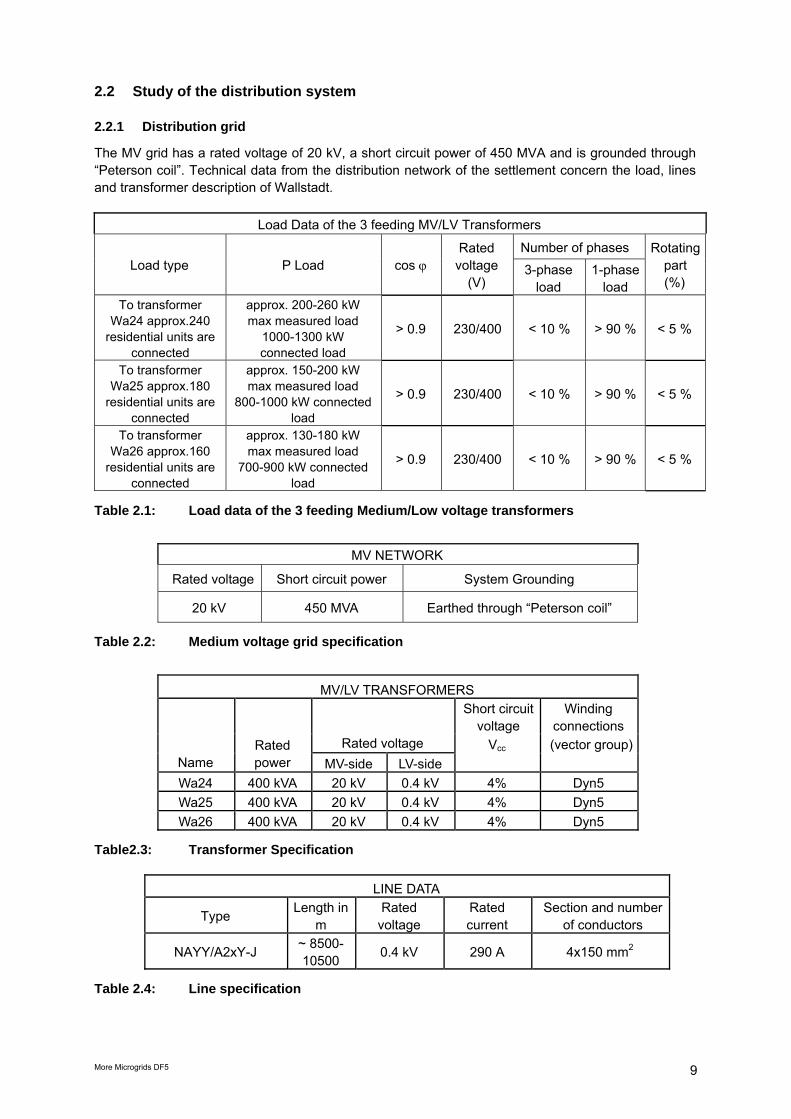
The MV grid has a rated voltage of 20 kV, a short circuit power of 450 MVA and is grounded through “Peterson coil”. Technical data from the distribution network of the settlement concern the load, lines and transformer description of Wallstadt.
Load Data of the 3 feeding MV/LV Transformers
Number of phases Load type P Load cos ϕ
Rated voltage
(V) 3-phase
load 1-phase
load
Rotating part (%)
To transformer Wa24 approx.240
residential units are connected
approx. 200-260 kW max measured load
1000-1300 kW connected load
> 0.9 230/400 < 10 % > 90 % < 5 %
To transformer Wa25 approx.180
residential units are connected
approx. 150-200 kW max measured load
800-1000 kW connected load
> 0.9 230/400 < 10 % > 90 % < 5 %
To transformer Wa26 approx.160
residential units are connected
approx. 130-180 kW max measured load
700-900 kW connected load
> 0.9 230/400 < 10 % > 90 % < 5 %
Table 2.1: Load data of the 3 feeding Medium/Low voltage transformers
MV NETWORK
Rated voltage Short circuit power System Grounding
20 kV 450 MVA Earthed through “Peterson coil”
Table 2.2: Medium voltage grid specification
MV/LV TRANSFORMERS Short circuit
voltage Winding
connections Rated voltage Vcc (vector group)
Name Rated power MV-side LV-side
Wa24 400 kVA 20 kV 0.4 kV 4% Dyn5 Wa25 400 kVA 20 kV 0.4 kV 4% Dyn5 Wa26 400 kVA 20 kV 0.4 kV 4% Dyn5
Table2.3: Transformer Specification
LINE DATA
Type Length in m
Rated voltage
Rated current
Section and number of conductors
NAYY/A2xY-J ~ 8500-10500 0.4 kV 290 A 4x150 mm2
Table 2.4: Line specification

More Microgrids DF5 10
2.2.2 System analysis A Microgrid is characterized by loads, generators and the ability to run in islanding mode. To realize a Microgrid the necessary generation had to be quantified as well as the over-all consumption had to be known, together with the peak load and the period of peak demand to estimate the renewable sources or CHP needed for compensation. Therefore load profiles have been generated by the software SINCAL. Besides the total loads, the amount of controllable loads and the ratio of controllable to uncontrollable loads had to be determined. The energy of a controllable load offers the possibility for load shifts. If the energy of a load is shifted to a later time, the power flow at the present time is reduced. Beside load shifting load shedding is another option to reduce consumption in a certain time period. Some application/consumers can better shed than curtail power. Shifting the use of a washing machine to a later time has only little effects on the present power flow (except maybe through the water heating period), since washing machines have only several cycles a week and therefore are idle most of the time. But deciding to run the machine at noon or evening is shifting the consumed energy. A freezer is not able to shift energy in a large amount, since it has to run more or less all the time. But it might reduce the power consumption at one time. Both effects are important for the balance of generation and load. The load analysis was focused on two main topics: • the amount of used electricity and the time of use and • the ratio of sheddable and non-sheddable electricity demand. The evaluation of the ratio of sheddable and non-sheddable load focused on two subtopics: • Electricity shed in the experiment “Washing with the Sun” • Potential of sheddable electricity in the ecological settlement Mannheim-Wallstadt
Figure 2.8: Comparison of measurements at the transformers and the compiled profile for
8-15 January 2007 (y-axis: ratio of power and peak power) Standard load profiles and the analysis of the amount of sheddable loads are based on measurements and logs of the use of household appliances in the settlement. Data for load analysis were collected in connection with the project «Washing with the sun» implemented in August and September 2006. Besides the data collected (see below), measurements at the transformer stations in the ecological settlement Mannheim-Wallstadt were made. The objective of «Washing with the sun» experiment is to evaluate the willingness of customers to
More Microgrids DF5 11
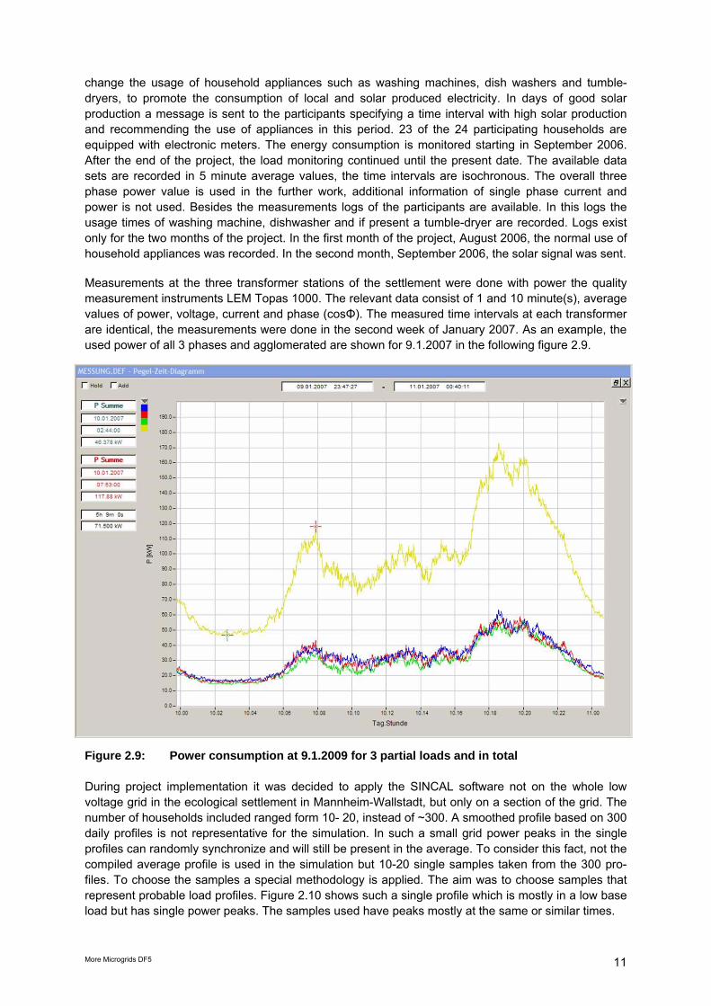
change the usage of household appliances such as washing machines, dish washers and tumble-dryers, to promote the consumption of local and solar produced electricity. In days of good solar production a message is sent to the participants specifying a time interval with high solar production and recommending the use of appliances in this period. 23 of the 24 participating households are equipped with electronic meters. The energy consumption is monitored starting in September 2006. After the end of the project, the load monitoring continued until the present date. The available data sets are recorded in 5 minute average values, the time intervals are isochronous. The overall three phase power value is used in the further work, additional information of single phase current and power is not used. Besides the measurements logs of the participants are available. In this logs the usage times of washing machine, dishwasher and if present a tumble-dryer are recorded. Logs exist only for the two months of the project. In the first month of the project, August 2006, the normal use of household appliances was recorded. In the second month, September 2006, the solar signal was sent. Measurements at the three transformer stations of the settlement were done with power the quality measurement instruments LEM Topas 1000. The relevant data consist of 1 and 10 minute(s), average values of power, voltage, current and phase (cosΦ). The measured time intervals at each transformer are identical, the measurements were done in the second week of January 2007. As an example, the used power of all 3 phases and agglomerated are shown for 9.1.2007 in the following figure 2.9.
Figure 2.9: Power consumption at 9.1.2009 for 3 partial loads and in total During project implementation it was decided to apply the SINCAL software not on the whole low voltage grid in the ecological settlement in Mannheim-Wallstadt, but only on a section of the grid. The number of households included ranged form 10- 20, instead of ~300. A smoothed profile based on 300 daily profiles is not representative for the simulation. In such a small grid power peaks in the single profiles can randomly synchronize and will still be present in the average. To consider this fact, not the compiled average profile is used in the simulation but 10-20 single samples taken from the 300 pro-files. To choose the samples a special methodology is applied. The aim was to choose samples that represent probable load profiles. Figure 2.10 shows such a single profile which is mostly in a low base load but has single power peaks. The samples used have peaks mostly at the same or similar times.

More Microgrids DF5 12
Figure 2.10: Typical client power profile (red in kW) and energy consumed (blue in kWh) With the redundant use of both approaches the deficiency of either approach can be compensated. In the logs, the daily use of machines is recorded. With this information the daily dispersion of machine use, as average over a month, is evaluated. Since the logs show that there are no significant differences between the usage on weekdays and on weekends, all days of the month can be regarded at once. This is done separately for the three observed machine types, washing machine, dish-washer, and tumble-dryer.
Figure 2.11: Comparison of the use of domestic appliances without recommendation for use
(in August 2006; blue bars) and with recommendation for use between 10-13h (in September 2006; red bars). This figure shows a significant shift of loads to the recommended time span.

More Microgrids DF5 13
2.3 Generators and loads As already explained above the ecological settlement Mannheim-Wallstadt is subject to several research projects of MVV Energie. It has been developed for long term testing of innovative smart grid solutions. The More Microgrids project has been the first project in this area. The first task was to motivate the inhabitants of this settlement to join our experiments and co-operate for the establish-ment of innovative smart grids concepts. The grid section had different generators and large scale controllable loads, which are requirements for a microgrid.
Figure 2.12: Available generators and loads (including back up system) studied in detail
Figure 2.13: Location of selected microgrid components (generators, loads, storage)
PV System 1 14,28 KWp PV System 2 9,18 KWp
Pump 3 x 0,75 KW
Kinderhaus Convector heater: 10.3 KW 3 air conditioners each 3.3kVA
Battery 105Ah, 21A, 5h Sunny-Backup System

More Microgrids DF5 14
This chapter is focusing on available generators and loads, and also on storage capacities in order to investigate the possibilities to study aspects of a microgrid in subgrids within the Wallstadt settlement. It also presents the loads and generators that are used in the context of satellite experiments done within the context of the More Microgrids project such as remote control of devices. The following figures provide an overview on the originally planned loads and generators. The loads and generators shown were all investigated for use but not necessarily used at the same time as will be detailed later on. 2.3.1 Loads Loads in the distribution grid can be separated in two categories: Private households with individual smaller loads, and several large-scale loads that can in principle be controlled by the distribution company. In respect to a load reduction in case of a need for balancing with internal generators in islanding mode, the controllable loads are of primary interest. Main controllable loads are described below. Water pumps The water pumps provide small artificial creeks in the settlement with water. This contributes to the high oxygen level in the small ponds in the settlement. The pumps can be stopped for a maximum of 5 times for one hour within a 24 hours time period. It is important to inform the inhabitants of these experiments in advance, because they watch the fountains carefully. There must be a visible sign that tells the inhabitants if the interruption is intended during the test phase or an unintended error. Furthermore, the municipal wastewater department of the City of Mannheim (“Stadtentwässerung“), must always be informed about the current status of the tests. This could be realised via a potential free output. In total, there are three identical water pumps at the location „Number 2“ which can be controlled separately or in all possible constellations. The following figure shows the electric control panel of the pumps and the following table provides technical specification of one water pump:
Figure 2.14: Electric board of the water pumps

More Microgrids DF5 15
Load type water pump Control on/off Power continuously 0,75 kW Starting current 15 A Grid connection single phase Restriction for experiment 0-5 interruptions per day; duration of 0-1 hour per interruption Location street name: Pfeilkrautweg in Mannheim-Wallstadt; marked as Nr. 2
in the map (Figure 2.13) Table 2.5 Technical specification of the water pump in Mannheim-Wallstadt Convector In the children’s day care centre, the Kinderhaus, the staff uses a convector for warming up meals for the children. Normally the convector runs continuously from 10am to 2pm. It turns on and off irregularly in order to keep a steady given temperature. In our tests, we could interrupt the heating process in the time between 10:30 am and 2 pm maximum allowable for 5 minutes and for 6 times within this time period. The staff of the day care centre has agreed to participate in the experiment. However, they must be informed at any time about the current status of the experiment. This could be realized by a visual sign at the convector (e.g. a lamp). The technical specifications of the convector are provided in the following table and a view in the following figure: Load type Electric oven for low temperatures – Convector Control on/off Power Peak of 10,3 kW, irregularly Starting current 25 A Grid connection three phase Restriction for experiment 0-6 interruptions between 10:30 am and 2 pm; duration of 0 - 5 min
per interruption Location street name: “Wertheimer Straße” in Mannheim-Wallstadt
marked as number 3 in the map(Figure 2.13) Table 2.6: Technical specification of a convector (electric oven) in the Kinderhaus
Figure 2.15: View of the convector (electric heater for meals) in the Kinderhaus Note: The convector has finally not been included in the experiments because its power of 12.5 kW would have exceeded the possible generation provided by the PV in the Kinderhaus based islanding mode, and considering the participation of other loads.

More Microgrids DF5 16
Three air conditioners: In the Kinderhaus additionally 3 air conditioners were installed to be used as controllable loads with the following specifications: Load type Air conditioner Control on/off Power 3,3kVA each; 9,9kVA for all three Starting current 14 A Grid connection one phase Restriction for experiment No restrictions Location street name: “Wertheimer Straße” in Mannheim-Wallstadt
marked as number 3 in the map (Figure 2.13). Table 2.7 Technical specification of the air conditioners in the Kinderhaus Mannheim 2.3.2 Generators In the grid segment several PV systems were installed and one Whispergen Micro CHP. The WhisperGen micro CHP installed in the subgrid is privately owned. It was included in the investigation as it is an excellent example for further potential generators but could not be included in full-scale in the experiments. The owner was not allowing a remote control as he had no sufficient heat buffer in case of a remote switching on/off of his micro CHP Two PV systems installed on the roof of the Kinderhaus are remotely controlled (see Figure 2.12.). The following table adds more technical details. PV panels – type PV system, crystalline modules Nominal power PV system 1 14.28 kWp Nominal power PV system 2 9,18 kWp Inverter: Manufacturer SMA, Sunny, data sheet inverter of SMA Power 1 SMC 7000 TL 3 string a 14 moduls Power 2 SMC 7000 TL 3 string a 14 moduls Power 3 SMC 7000 TL 3 string a 14 moduls Power 4 Sunny Boy 2100 TL 1 string a 12 moduls Grid connection single phase (specify which phases) Control Only monitoring Location “Wertheimer Strasse”; Mannheim-Wallstadt; On the roof of the
day care center (marked as number 1 in Fig. 2.12) Table 2.8 Technical specification of PV systems installed on the roof of the Kinderhaus The PV panels were attached to inverters which are then connected to a back-up system. The “Sunny back up” system is further detailed in section 3.1: Realisation of the islanded mode in the Kinderhaus. As one important result of the field test, the communication was successfully tested for all the loads and generators described in this chapter.

More Microgrids DF5 17
2.4 Multi agents system in the Mannheim field test The main concept of the Multi Agent System (MAS), as described in detail in the deliverables of WPB, is the decentralized decision process. Thus a number of agents (software entities) coordinate and collaborate in order to solve a problem or optimize a process. The agents control the loads of the test site and also monitor the production and storage units. The main element of MAS is the agent, which is a physical entity, or a virtual one. In our application the physical entity is a micro-source or a controllable load and the virtual one a piece of software that coordinates the agents. Although there is no strict definition about what an agent is, the literature provides some basic characteristics summarized in figure 2.16.
Figure 2.16: The Basic Characteristics of the agents The first characteristic is that an agent can be a physical entity that acts in the environment or a virtual one, i.e. with no physical existence. In our case the physical entity is the agent that controls directly a microturbine and a virtual one a piece of software that makes bids to the energy market or stores data in a database. An agent is capable of acting in the environment, i.e. the agent changes its environment with its actions. A diesel generator by altering its production changes the set points of the other local units, changes the voltage level of the adjacent buses and in a more global point of view changes the security level of the system [the stability of the system in case of a short circuit for example]. Agents communicate with each other and this could be regarded as part of their capability for acting in the environment. As an example, let’s consider a system that includes a wind generator and a battery system: the battery system uses power from the wind turbine to charge and to discharge it, in times of no wind. In order to achieve this operation optimally, the two agents have to exchange many messages. This is a type of action because the environment is altered in a different way by this communication, rather than if the two agents were acting without any kind of coordination. Significant part of the communication is the ontology, which is a set of vocabulary understandable by all agents.

More Microgrids DF5 18
Figure 2.17: The agents need a common vocabulary Agents have a certain level of autonomy, which means that they can take decisions without a central controller or commander. To achieve this, they are driven by a set of tendencies. For a battery system a tendency could be: “charge the batteries when the price for the kWh is low and the state of charge is low, too”. Thus, the MAS decides when to start charging based on its own rules and goals and not by an external command. In addition, the autonomy of every agent is related to the resources that it possesses and uses. These resources could be the available fuel for a diesel generator. Another significant characteristic of the agents is that they have partial or none at all representation of the environment. For example, in a power system the agent of a generator knows only the voltage level of its own bus and, maybe, it can estimate what is happening in certain specific buses. However, the agent does not know what is happening in the whole system. This is the core of the MAS technology, since the goal is to control a very complicated system with minimum data exchange and minimum computational demands. Finally, another significant characteristic is that an agent has a certain behaviour and tends to satisfy certain objectives using its resources, skills and services. An example of these skills could be the ability to produce or store power and an example for the services could be the ability to sell power in a market. The way that the agent uses the resources, skills and services characterizes its behaviour. As a consequence, it is obvious that the behaviour of every agent is formed by its goals. An agent that controls a battery system and its goal is to supply uninterruptible power to a load will have different behaviour from a similar battery, whose primary goal is to maximize profits by bidding in the energy market. The characteristics outlined above allow for several benefits that the Multi-Agent Systems can offer, as far as the control of the Microgrid is concerned. Taking into account that a Microgrid is comprised mostly from small-size production units, a centralized control approach would prove to be a quite expensive choice with relevance to the cost of the production units. Although in large production plants, the control units reflect only a small percent of the overall cost, this is not the case for small-size production units. Thus, low-cost innovative solutions must be investigated. The implementation of an intelligent agent requires only a processing unit with a microprocessor, similar to those found in every PC. Furthermore, depending on the intelligence of the agents, they are able to act without being constantly supervised, and, therefore, there is no need for an operator of the system. Additionally, the agents allow for advanced “plug and play” capabilities. Based on their characteristics, the agents can adapt to their environment and act accordingly in order to accomplish the goals set. For example, in the future electricity grids, power production units are expected to connect and disconnect from the grid in a stochastic manner. The agents are able to recognize autonomously when a new production unit has been connected to the grid, and adapt their behaviour in order to optimize
More Microgrids DF5 19
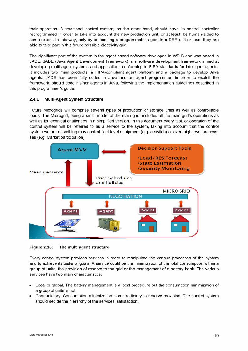
their operation. A traditional control system, on the other hand, should have its central controller reprogrammed in order to take into account the new production unit, or at least, be human-aided to some extent. In this way, only by embedding a programmable agent in a DER unit or load, they are able to take part in this future possible electricity grid The significant part of the system is the agent based software developed in WP B and was based in JADE. JADE (Java Agent Development Framework) is a software development framework aimed at developing multi-agent systems and applications conforming to FIPA standards for intelligent agents. It includes two main products: a FIPA-compliant agent platform and a package to develop Java agents. JADE has been fully coded in Java and an agent programmer, in order to exploit the framework, should code his/her agents in Java, following the implementation guidelines described in this programmer's guide. 2.4.1 Multi-Agent System Structure Future Microgrids will comprise several types of production or storage units as well as controllable loads. The Microgrid, being a small model of the main grid, includes all the main grid’s operations as well as its technical challenges in a simplified version. In this document every task or operation of the control system will be referred to as a service to the system, taking into account that the control system we are describing may control field level equipment (e.g. a switch) or even high level process-ses (e.g. Market participation).
Figure 2.18: The multi agent structure Every control system provides services in order to manipulate the various processes of the system and to achieve its tasks or goals. A service could be the minimization of the total consumption within a group of units, the provision of reserve to the grid or the management of a battery bank. The various services have two main characteristics: • Local or global. The battery management is a local procedure but the consumption minimization of
a group of units is not. • Contradictory. Consumption minimization is contradictory to reserve provision. The control system
should decide the hierarchy of the services’ satisfaction.

More Microgrids DF5 20
Figure 2.19: The services provided by the control system The two categories mentioned above, also reveal the main problem with Microgrid control: the complexity of the system. Figure 2.18 generally presents some of the several operations that should be adopted for the electrical control of the system.
Figure 2.20: A main goal of decentralized control is to deal with complexity As an example we could consider two of these operations: the control of total production and the control of a specific unit. Although the similar control process in the main grid would have been described as central, it is actually not, since the central SCADA does not take into account local information (e.g. temperature of a boiler) in order to decide the set point for a specific Power Station. The central SCADA has knowledge of only two values, frequently updated by the Power Station personnel: the Maximum and the Minimum production capability. Thus, it sends a set point between these two values. Several people may however urge that the DG units are very simple and therefore simple rules and models can be inserted in the central control system. This is wrong if we consider the operation of hundreds of DGs (scalability) the system becomes significantly complex or even infeasi-ble to solve (computational complexity).

More Microgrids DF5 21
The final conclusion about the control operation of the Microgrid is that the main challenge is not to deal with complex sub-systems (e.g. large power stations) but to deal with a complexity derived by the aggregation of several simple sub-systems as well as with several different services. Therefore the Decentralized Control approach actually emulates the operation of the larger system where several controls are distributed and thus is able to keep the complexity bounded as presented in Figure 2.19. 2.4.2 Jade Platform JADE (Java Agent Development Framework) is a software development framework aimed at developing multi-agent systems and applications conforming to FIPA standards for intelligent agents. It includes two main products: a FIPA-compliant agent platform and a package to develop Java agents. JADE has been fully coded in Java and an agent programmer, in order to exploit the framework, should code his/her agents in Java, following the implementation guidelines described in this programmer's guide. This guide supposes the reader to be familiar with the FIPA standards1, at least with the Agent Management specifications (FIPA no. 23), the Agent Communication Language, and the ACL Message Structure (FIPA no. 61). JADE is written in Java language and is made of various Java packages, giving application program-mers both ready-made pieces of functionality and abstract interfaces for custom, application depend-ent tasks. Java was the programming language of choice because of its many attractive features, par-ticularly geared towards object-oriented programming in distributed heterogeneous environments; some of these features are Object Serialization, Reflection API and Remote Method Invocation (RMI).The standard model of an agent platform, as defined by FIPA, is represented in the figure 2.21.
Figure 2.21: The AMS (Agent Management System) platform The Agent Management System (AMS) is the agent who exerts supervisory control over access to and use of the Agent Platform. Only one AMS will exist in a single platform. The AMS provides white-page and life-cycle service, maintaining a directory of agent identifiers (AID) and agent state. Each agent must register with an AMS in order to get a valid AID. The Directory Facilitator (DF) is the agent who provides the default yellow page service in the platform. The Message Transport System, also called Agent Communication Channel (ACC), is the software component controlling all the exchange of messages within the platform, including messages to/from remote platforms. JADE fully complies with this reference architecture and when a JADE platform is launched, the AMS and DF are immediately created and the ACC module is set to allow message communication. The agent platform can be split on several hosts. Only one Java application, and therefore only one Java Virtual Machine (JVM), is executed on each host. Each JVM is a basic container of agents that pro-vides a complete run time environment for agent execution and allows several agents to concurrently execute on the same host. The main-container, or front-end, is the agent container where the AMS and DF lives and where the RMI registry, that is used internally by JADE, is created. The other agent containers, instead, connect to the main container and provide a complete run-time environment for the execution of any set of JADE agents.

More Microgrids DF5 22
3. Realized experiments in Mannheim-Wallstadt 3.1 Introduction This chapter describes the experiments that have been realized in the Mannheim-Wallstadt field test site with a thorough description of how the experiments have evolved over four years of experiments. It was planned in 2005 in the project proposal to create a small microgrid, the MVV headquarters. At project start in 2006, MVV Energie selected the quarter “Mannheim-Wallstadt” as suitable test site for long term field tests and aimed to transform part of Mannheim-Wallstadt into a Microgrid. This required controllable loads, storage, negotiating agents and services. The aim was to communicate with these devices and to enable the Microgrid to switch between grid connected and islanding mode. As described in Chapter 2, in the context of the project, the team raised awareness for the topic of renewable energy and necessity to shift loads to host more renewable energy in a grid segment at the consumers and producers as well as the children who live in this estate. Main activity of awareness building was the installation of the VisiKid panel at the entrance of the Kinderhaus and the activity “Washing with the sun”. Solar energy is now integrated into the daily routine and educational work of the Kinderhaus. Children play interactively with VisiKid, and transport this message to their parents. In parallel, the team adapted the grid structure to allow for a microgrid with high penetration of renew-able energy and included the Kinderhaus as key stakeholder in awareness builiding into our experi-ments. To conclude the preparation of the grid, the team installed long term power quality monitoring equipment at the transformer stations. The analysis of the distribution system as well as of generators and controllable loads provided insight into feasibility of microgrid experiments. The supplied grid segment is not an experimental station but a normal distribution grid that is subject to German regulatory and technical framework and doesn´t allow for any additional failures such as frequency or voltage fluctuations or even temporal black-outs. To ensure the failure-free power supply in such a large subgrid, an internal calculation resulted in the need of a large electricity storage equivalent to a power supply of ~50 kW over at least one hour. The storage would have required to rent or buy a piece of land to install a garage-size container. But a suitable piece of land was not in the property of MVV, and the delivery of a 50 kW storage in the context of another European project was delayed to early 2010. As a result, this storage could not be realized within the project time and budget. However a smaller storage was available at the kinder-garten as part of the sunny back-up system. All distributed generators and loads mentioned in chapter 2 are privately owned. As a consequence, all tests with these devices are subject to approval by the owners. This is one important legal, techni-cal and psychological framework condition for all microgrids experiments. Fully available were the 2 PV systems installed at the kindergarden. The panels were connected with a sunny back-up system that included a battery as a smaller storage device. The main aim of this storage was not to supply any loads compensating missing electricity supply in case of island mode as it was the aim to balance supply and demand. But for the time this balancing was established (<1s) the storage was needed to stabilise the grid (frequency, voltage). Given this framework and grid simulation results, the team decided to realize three major technical experiments: • First, communication with all generators and loads as described in Chapter 2. • Second, transition from grid connection to islanding mode in a small microgrid, the Kinderhaus. • Third, test of functionality of the Multi-Agent system

More Microgrids DF5 23
3.2 Transition from grid connected to islanded mode in the Kinderhaus The team prepared the Kinderhaus as microgrid comprising two PV systems with a sunny back up system, controllable loads and adding a sufficiently designed battery storage as buffer able to supply 10 kW for 1 hour. The “Kinderhaus” has been the main focus of our further experiments. The Sunny-Backup System was installed in the Kinderhaus to allow part of the loads and generation to behave as microgrid. To prove the feasibility of an iterative switching from islanded to grid con-nected mode and vice versa an additional battery for stabilizing the frequency was installed in combi-nation with a system of inverters that are able to realize an islanding mode. This battery (48 V105 Ah, 21 A for 5h) has been used in combination with the system for the only purpose of regulating the frequency while switching to the islanding mode. The following figures show the installed system in the Kinderhaus and the electrical scheme of the 3 phase Sunny Backup System.
Figure 3.1: The Sunny-Backup system and its batteries (at the bottom) in the Kinderhaus
Figure 3.2: Electrical scheme of the innovative 3-phase Sunny-Backup system

More Microgrids DF5 24
The Sunny-Backup System has been connected to a part of the loads in the inside of the Kinderhaus, and an islanding mode has been flawlessly realised as the following figures show. In figure 3.3. the frequency development is shown. At ~15:40 and next day at ~11:40 for some 15 min the kinderhaus was disconnected from the grid running in islanded mode. During this periods the frequency increased from 50 to 52 Hz caused by un unbalance between generation and loads (less loads are connected to the sunny backup-system during the period of the islanding). After reconnection to the grid the frequency quickly returns to 50 Hz imposed by the dominance of the grid. Figure 3.3 documents the successful switch from the islanded to the grid connected mode and vice versa.
Figure 3.3: Frequency measurement at the transfer from grid-connected to islanding mode
and vice versa in the “Kinderhaus” The following figure 3.4 focuses on another aspect the current measurements during the islanding periods mentioned before are indicative of power consume of the islanded loads in the kinderhaus, lightening and phone devices –that is-. The aim of this figure is to show that actual loads were con-nected to the three inverters of the sunny Backup- system. The 3 phases are connected to differrent loads. Note, that 1 A corresponds to a power consumption of 230 W, only – all loads shown are quite moderate. The measures of the 3 phase current are taken in parallel to the frequency measurements shown above, i.e. exactly at the same time the kinderhaus was in islanding mode (for approx. 15 min starting around 15:40 and next day starting around 11:40) and for the other times connected to the grid. At the time of measurement there was no ‘intelligence’ disconnecting any consumer of the 3 phases during islanding mode. Thus, the consumption is not related to islanding or grid connected power supply. There is just a small effect visible indicating the switch from grid-connect to island mode and back for the blue phase: around the islanding mode operation consumption connected to the blue phase are almost stable with 1.2 A. Howver, during islanding mode around 15:45 and 11:45 next day there is a little drop in consumption by ~3% from 1.20 to ~1.17 A. This is thought to be caused by the inverter that tries to stabilize voltage at ~230 V and for this reduces current from 1.20 to 1.17 A.

More Microgrids DF5 25
Shortly before the re-connection to the grid at 15:50 deliberately some lamps connected to the red phase was switched on and an rise of the current can be seen from ~0.1A to 0.7 A (~120 W load) with a further rise to 1.4 Amps and more adding more consumers.
Figure 3.4: RMS current measurement at the transfer periods from grid-connected to islan-
ded mode and vice versa in the “Kinderhaus”

More Microgrids DF5 26
3.3 Test of functionality of the agents 3.3.1 Set-up In order to demonstrate the feasibility of the demand side management in a future Microgrid with a balancing storage, loads outside of the Kinderhaus have also been detected and prepared for the experiments. Initially, the outdoor loads that have been identified were a WhisperGen and three water pumps. Finally, we have considered the water pumps since the privately owned WhisperGen was not available for tests. Communication with these loads has also been prepared in order to enable all loads and generators to communicate and react to the demand side management software. A powerline connection of these loads was established, linked to the location “Kinderhaus” and tested by the MVV and the company Power Plus Communication (PPC) as the following figure shows. PPC operates the Mannheim Powerline and is research partner in the follow-up E-Energy research project “Model City Mannheim”.
Figure 3.5: MVV and Power Plus Communication (PPC) testing the broadband powerline
network in the concerned site Another step was to allow the agent-controllers of the NTUA to open loop control the loads. The I/O modules provided by the NTUA were designed for laboratory experiments, so an industrial alternative was necessary. The following figure shows the remote control chain as it was realized:
Figure 3.6: The loads control chain for the example of remote control of the pumps The communication equipment for the remote data inquiry was implemented and successfully tested, partially continued at begin of 2009 (e.g. the programming of the actuator/IO modules and the improved agent for the intelligent load management test and implementation). Powerline enabled I/O modules have been used for this purpose. The following figure shows one of the devices:

More Microgrids DF5 27
Figure 3.7: I/O module used in the site as a preparation to the experiment The same I/O modules have been tested inside of the Kinderhaus, and the loop control loads control was successfully demonstrated. The following figure shows the I/O BPL (broadband power line) installation control board inside the Kinderhaus:
Figure 3.8: Built in BPL-enabled I/O modules in the Kinderhaus This actuator has been used to demonstrate the ability of the NTUA software of remote controling the loads. At a later stage of the experiments, the hardware had to be modified so as to comply with the actual functionalities of the NTUA agents which are amongst others receiving consumption and generation data from the loads and generators successively. 3.3.2 Functionality test The components of the field test had to be adjusted to the novel situation, considering the constraints we had to deal with. The final status of the components and experiments realized in October 2009 included: • Two PV-Panels a 23.5 kWp as negotiating generators • Water pumps a 750 W each as negotiating loads • Three air conditioners in the Kinderhaus a 3.3kVA each as negotiating loads • A Sunny-Backup System and its accordingly dimensioned storage a 105 Ah, 21A, 5h as a unit to
realize the islanding mode
More Microgrids DF5 28
• Agent controller-software as virtual negotiators either on the behalf of loads or generators • Communication and measurement devices (comsumption and generation) - as follows: Control Equipment: 1. Ethernet Switch 2. In order for multiple modules with inherent IP addresses communicating on any network protocol to
be connected to the same point a switch is to be used. 3. In the framework of the experiments the ADAM-6520 Ethernet switch was installed. 4. AI/DO module 5. A module receiving analogue measurements as input was implemented for tests concerning the
load control within the Microgrids concept. For the load control itself a module controlling switching relays was installed. The combination of the above two functions led to analogue Input/Digital Output modules.
6. 24V feeder for the AI/DO modules 7. Current TF 8. Current transformers were required for the measurements read out from loads and sources. Two
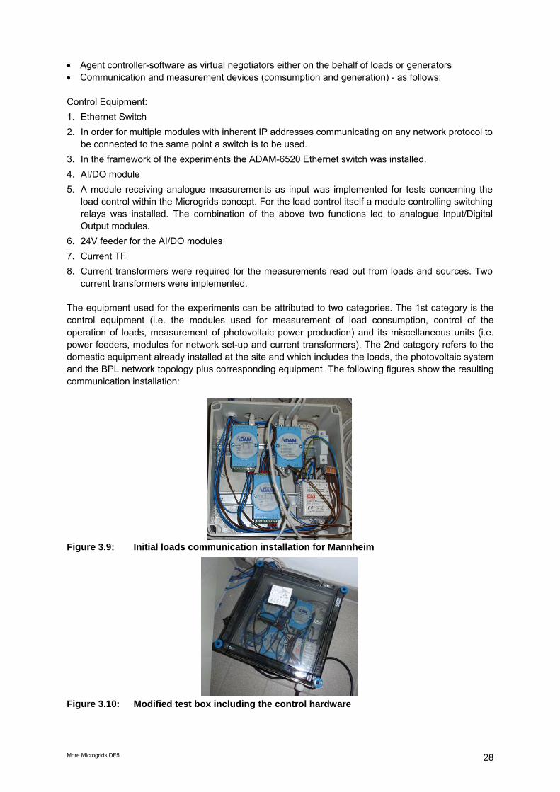
current transformers were implemented. The equipment used for the experiments can be attributed to two categories. The 1st category is the control equipment (i.e. the modules used for measurement of load consumption, control of the operation of loads, measurement of photovoltaic power production) and its miscellaneous units (i.e. power feeders, modules for network set-up and current transformers). The 2nd category refers to the domestic equipment already installed at the site and which includes the loads, the photovoltaic system and the BPL network topology plus corresponding equipment. The following figures show the resulting communication installation:
Figure 3.9: Initial loads communication installation for Mannheim
Figure 3.10: Modified test box including the control hardware

More Microgrids DF5 29
The project activities in the Mannheim location were focused on the management of loads exposed to fluctuating generation. A combination of agents’ management abilities and the necessary communication tools between the agents and their corresponding generators and/or loads was necessary; therefore a power-line network has been made available. In the network, IP addresses have been assigned to each load and generator involved in the sphere of action of the agents. The experiments carried out have shown that for instance it was possible to control three air-conditioning units by increasing or decreasing their total consumed power according to a defined percentage of photovoltaic power virtually assigned to them. The following figures show the control modules installed on the generators:
Figure 3.11: Generators communication for Wallstadt- Sunny Back-up System
Figure 3.12: Modified control installation of the generation 3.3.3 Test of the negotiation abilities of the NTUA agents Experiments aiming at testing the functionalities of the agents developed by NTUA were initially involving loads and generators in the Kinderhaus as well as loads outside of the Kinderhaus, i.e. the water pumps. In the development of the project the team focussed exclusively on Kinderhaus-based experiments. Broadband Powerline (BPL-) based experiments The planned experiments were involving water pumps (outdoor), air conditioners and PV-Panels in the Kinderhaus. These experiments have been named BPL-based.

More Microgrids DF5 30
Figure 3.13: BPL network in the test site Given the BPL Network, the first session of experiments was focused on running a negotiation with the main agent hosted on a PC located in the transformer-house facility and the load and production agents in the Kinderhaus facility. That way the BPL network would be used for exchanging messages and executing the negotiations. A generation agent would be measuring the generated power from the PV array and a 10% of that production would be virtually assigned as a consumption limitation to the loads which would be accordingly shed from load agents (also taking measurements of the power consumed) in order either the limitation or the energy consumption to be kept at a desired level. Three load agents were assigned to the three AC units respectively both measuring the consumption and switching ON and OFF the corresponding relays according to the outcome of the negotiations ran1. LAN based experiments The second session of experiments was executed over the LAN inside the Kinderhaus facility. The 10% over the PV production limitation of load consumption was kept and two parts were distinctively set up regarding the agents participating in the microgrid. The following figure shows the installation:
Figure 3.14: LAN connection between the agents, loads, and generators in the Kinderhaus
1 This part could not be realized for network incompatibility reasons, because the outdoor and indoor loads and
the generators were on different networks.

More Microgrids DF5 31
After the successful establishing of a communication between the agents, the air conditioners, and the sunny back-up system were tested. The tests have been successfully completed as a generation diffusion of the photovoltaic power has been made according to the negotiation of the three load agents (cf. chapter 2.4). All these experiments have been successfully completed inside the kinder-haus. The three loads agents negotiated between them which load is more likely to be disconnected, loads that where less important and did not need power had less priority, and the loads that needed immediate power, have been served. (cf. logs und CAD image) The following figure shows the successful negotiation by the load and generator agents, and a larger version of it is to be found in the appendix:
Figure 3.14: Screenshot of the Kinderhaus based experiments with LAN

More Microgrids DF5 32
4. Conclusions and future prospects The objective of the field test in Mannheim was to aggregate several distributed generators and controllable loads to form an interconnected microgrid as part of one real grid segment of the Mannheim low voltage grid. The field test focussed on seamless transition between grid connected and islanding mode and vice versa. Chapter 2 describes the successful preparation of one grid segment for microgrid operation: • Relevant study results of grid characteristics and power quality of this representative grid segment
in Mannheim are described • real profiles for controllable loads and generators are presented in detail. • Adaptation of grid segments served by MV/LV transformer WA24 to prepare it for islanding (less
loads, more DG) • Awareness building and social acceptance • Grid data can be forwarded online to future “microgrid control centres” (Janitza UMG 510). • Preparation of the field test to remain installed for education and demonstration purpose As a result, this test site is well prepared for further experiments with distributed generation or with novel system architectures for smart grids and microgrids in particular. Knowledge transfer between the field test team and academia has been secured during the whole project work. The multi agent system structure which had been developed in Work Package B of the More Microgrids project as well as the Jade Platform is explained to provide the rationale behind the experiments. Based on the above infrastructure for the field test and the newly developed multi agent sytem, Chapter 3 explains the realized experiments in the field test Mannheim-Wallstadt:
• Communication between loads and generation was implemented and tested. • Seamless transition from grid connection to islanding and back was shown without electricity
quality problems. This islanding test included a selection of the above described loads and generator within the Kinderhaus.
• Proof of functionality of the agents: The management of loads following on a fluctuating generation - backed up by storage – negotiated by the new agents was successfully tested.
Cost-benefit analyses were analysed in depth in Work Package G and H. Technical data of this deliverable DF5 served as input to above cost-benefit analyses. This chapter discusses the resulting conclusions, lessons learnt and future prospects. The intention is to serve as input to ongoing or following projects in the context of microgrids and smart grids. In particular, these conclusions have already been shared in a work shop with the project teams of the European funded projects “Smart houses/smart grids”, GROW-DERS and the German E-Energy project “Model city Mannheim (moma)”. From the utility point of view, a microgrid offers the possibility to be operated as a coordinated entity in interconnected and islanded mode. It is expected that distributed generation located close to loads will reduce flows in transmission and distribution networks with two main results: (i) reduced losses and (ii) offering the potential for reduced network asset investments. Furthermore, the presence of generation close to demand contributes to increased service quality at the end customer. Microgrids can provide network support in times of stress by relieving congestions and supporting restoration of the grid after faults. The latter was the main focus of the field test Mannheim-Wallstadt.

More Microgrids DF5 33
Technical and social challenges and solutions in the project In contrast to traditional power grids which have rotating masses, microgrids are dominated by inverter at the DER (distributed energy resources) interfaces, offering the possibility for more flexible operation. The experience with the Sunny Backup System was satisfactory, since the seemless transition between island and grid connected modes has been successful implemented. A further implication of the field test is that it shows new possibilities to stabilize the supply of buildings or grid segments in the constellation of smart grids, since during congestions times or grid failures by (intentional) islanding the electric grid of the building or a grid segment. This is an important business case that should be studied in depth. Storage (batteries) has been used only for frequency control during the switching periods from island to grid and vice versa. The planned large storage to realise a larger islanding grid was not available in time due to difficulties in buying the needed piece of land and delays in another research project that was supposed to provide the battery from its budget. A number of problems were experienced due to the work in real grids, with real customers facing real operation problems (e.g. that the powerline internet connection had to be reinforced according to the field test time schedule) The cooperating agents each responsible for either a load or a generator/storage ensure the balance between generation and consumption in a given island. This technology needs to be further studied in order to include intentional islanding scenarios. Microgrids can contribute to procedures for ‘self healing grids’. This should be studies in follow-up projects. Lessons learnt
Additional lessons learnt during field test performance include
• Synergies with other research projects help to realize more valuable results with research budgets, but it is complex to arrange the correct timing due to possible delays in development
• It is recommended in to consider full formal procedure to pass from laboratory stage to go life in a real system.
• Communities are interested in using renewable energy, and education should cope with this fact • Unbundling in the European electricity market creates additional challenges for the integration of
distributed generation. Field tests are more difficult to realize due to additional interfaces between unbundled subsidiaries within one group, e.g. at MVV Energie group. Benefits of microgrids and win-win situations are hard to realize under the current regulatory framework.
• Social acceptance by real prosumers requires more efforts and than expected • Children´s education and in particular the Kinderhaus for children aged 2-6 years is a very good
starting point for awareness building for our next generation and their parents. Future prospects
The ability to work in islanding mode increases the security of supply. This is less important for German meshed grids but could be well studied here under real conditions without endangering the power supply to customers. Many utilities, especially with weaker grids therefore are interested in developing grid segments to microgrids able to run in island mode during times of congestion or grid failures. This business case will be treated in more depth in several upcoming projects such as in the German national projects E-Energy. Research regarding the development of the load controllers is ongoing in other research projects (at NTUA). The research focuses in three areas: (i) research in the hardware and cheaper implemen-

More Microgrids DF5 34
tations, (ii) research in the algorithms and finally (iii) software development for mass applications (SOA architectures). The microgrids installations remain installed for educational and demonstration purposes. The demonstration has been integrated into the educational concept of the Kinderhaus. Renewable energy and the timely value of electricity is now part of the daily routine and the annual curricula for the children. Further schools in Mannheim would like to follow the visualization and experiments realized at this Kinderhaus. To conclude, the field test is successful and sustainable in that results have contributed to identify further research topics and prepare the infrastructure and our “prosumers” for follow-up projects, most visibly the E-Energy project “Model City Mannheim”. 5. References Paola Schlichting „Dezentrales Energiemanagement in Kombination mit neuen Tarifmodellen“, Master Thesis, MVV Energie and University of Applied Sciences, Mannheim, Germany, March 2006 Jens Röck “Integration dezentraler Anlagen ins Niederspannungsnetz: Technische Beschreibung der Siedlung Wallstadt“ (Integration of decentralized generators in the low voltage grid: technical description of the settlement Wallstadt) – Semester work, MVV Energie and University of cooperative education, Mannheim, Germany, August 2006 Patrick Harbarth „Smart Metering: Elektronische fernauslesbare intelligente Stromzähler“, Diploma Theses, MVV Energie and University of Applied Sciences, Mannheim, Germany, December 2006 Thomas Schaupp „Design of a test site for agent based microgrid management with dispersed generation in a real distribution grid“, Diploma Thesis, MVV Energie and University of Applied Sciences, Mannheim, Germany, March 2007 Mathias Düerkop „Untersuchung typischer Netzstrukturen im Hinblick auf die Simulation einer intelligenten Integration von dezentralen Erzeugern in Verteilnetze“ (Analysis of typical grid topologies with respect to simulation of an intelligent integration fo distributed generators in distribution grids), Diploma Thesis, MVV Energie and University of Applied Sciences, Mannheim, Germany, August 2007 Britta Buchholz, Thomas Erge, Nikos Hatziargyriou “Long Term European Field Tests for Microgrids”, in: Proceedings of PCC Nagoya 2007, Nagoya, Japan, April 2007
Nicolai Herrmann, Sebastian Gölz, Britta Buchholz „Washing with the sun: Results of a Field Test for the Use of Locally Generated Renewable Electricity and Load Shifting in Households“ in: International Journal of Distributed Energy Resources, Volume No. 4, October-December 2008, ISSN 1614-7138
Britta Buchholz, Nikos Hatziargyriou, Christine Schwaegerl, Sjef Cobben, Nicolai Herrmann „International field experiences and cost-benefit analyses for the transition towards active distribution networks“, in: Proceedings of CIGRE Session 2008, Paris, France, Paper C6-205, August 2008
Britta Buchholz, Andreas Kiessling, David Nestle „Individual Customer´s Influence on the Operation of Virtual Power Plants“, in: Proceedings of IEEE PES-GM 2009, Calgary, Canada, July 2009
6. Acknowledgements We kindly acknowledge partial funding of the European Commission under FP6. We thank the director of the Kinderhaus for her enthusiastic co-operation in this project. We thank the City of Mannheim for hosting the experiments and for co-operation. We thank the owner of the PV system and all participants in our experiments.

More Microgrids DF5 35
Appendix: Enlargement of the screenshot Fig.3.13 for improved readability