CONTRACER CV-2100 SERIES
16
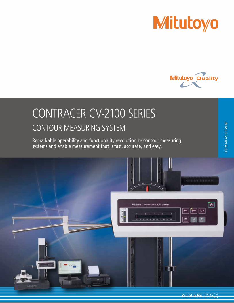
Bulletin No. 2135(2) FORM MEASUREMENT CONTRACER CV-2100 SERIES CONTOUR MEASURING SYSTEM Remarkable operability and functionality revolutionize contour measuring systems and enable measurement that is fast, accurate, and easy.
Transcript of CONTRACER CV-2100 SERIES
Bulletin No. 2135(2)
FORM
MEA
SURE
MEN
T
CONTRACER CV-2100 SERIESCONTOUR MEASURING SYSTEMRemarkable operability and functionality revolutionize contour measuring systems and enable measurement that is fast, accurate, and easy.

2
After a thorough analysis of all contour measurement operations, key operating functions are redesigned to enable fast, accurate and easy measurements.

3
4
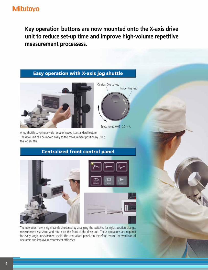
The operation flow is significantly shortened by arranging the switches for stylus position change, measurement start/stop and return on the front of the drive unit. These operations are required for every single measurement cycle. This centralized panel can therefore reduce the workload of operators and improve measurement efficiency.
A jog shuttle covering a wide range of speed is a standard feature.The drive unit can be moved easily to the measurement position by using the jog shuttle.
Easy operation with X-axis jog shuttle
Centralized front control panel
Key operation buttons are now mounted onto the X-axis drive unit to reduce set-up time and improve high-volume repetitive measurement processess.
Inside: Fine feedOutside: Coarse feed
Speed range: 0.02 - 20mm/s

5
The newly designed stand allows operators to quickly and easily move the drive unit to and from the measurement height without having to push or pull.Moreover, this stand is equipped with a reference stop for quick repositioning to the measurement height, which ensures an easy and highly efficient measurement flow.
By enabling faster X-axis movement and enhancing the stylus up/down functions, the drive unit can return to the measurement start position after auto-displacement of the stylus. This is especially useful when high volume repetitive measurements are being executed by a part program.
A quick-vertical-motion stand with remarkable operability
Highly efficient measurement
HandleFine-feed knob
Upside Bottom

6
"Pursuing high accuracy is our mission"Introducing a new highly accurate digital scale
Easy setup for highly accurate and efficient measurement
The detector unit (Z1 axis) is equipped with a highly accurate arc scale. This scale directly tracks the arc trajectory of the stylus tip so that the most accurate compensation can be applied to the scale output, which leads to higher accuracy and resolution.
The highly accurate digital arc scale not only improves measurement accuracy, but can also be set up easily.
Measurement range of detector: 50mmAccuracy: ±(2.5+|0.1H|) μm, where H is displacement
from mid-range position (mm)Resolution: 0.1μm (over entire measurement range)
Light emitter
Circular scale
Light receiver
The Circular Scale
Digital-scale detector Analog detector
Narrow
HighResolution
Constant Resolution
Entire measuring range
Measuringrange
Low
Wide
Easy setup without concern for the measurement range and magnification.
High resolution improves measuring accuracy.
Even after setup, the resolution is low.
Narrow measurement range and difficult setup.
Operators are free from bothersome operations such as measurement magnification switching and calibrating each magnification as required for analog instruments.
The combination of high accuracy and excellent operability allows for increased support of a wide range of measurement needs.

7
X-axis inclination handle is a standard feature
A range of options available according to the application
The CV-2100 series* is equipped with a drive unit inclination mechanism that enables inclined-plane measurement without changing settings.
Inclination angle (MAX): ±45°(For CV-2100M4)
CV-2100N4
Manual column stand for CV-2100N4*2
CV-2100M4Desktop PC
*1: If the CV-2100N4 is operated without the dedicated manual stand, the measuring range of the Z axis might be reduced, depending on the installation conditions. If you are considering using the CV-2100N4 without the stand, contact your local Mitutoyo sales office for advice.
*2: Optional accessory (refer to page 13).
*1
* For CV-2100N4, a manual column stand No.218-042 (refer to P13) is required (optional accessory.)

8
Contour Analysis Software: FORMTRACEPAKFORMTRACEPAK functions offer total support for measurement system control, surface roughness analysis, contour analysis, contour tolerancing, and inspection report creation.
To make only a single measurement, you can create a part programin the single mode. To measure multiple workpieces of an identicalshape, you can use the teaching mode.Since you can embed the entire flow, from making measurementto printing a report, into a part program, you can efficiently makemeasurements, analyze data, and output a report. A function is also provided that enables you to insert comments accompanied with photographs at desired timings, enabling you to embed the roles described in a measurement procedure document that specifies important points such as work settings.
To make immediate measurements, you can use the pull-downmenu to easily select and call up the desired operating procedure.
Help that can be viewed any time is incorporated into thesoftware. In addition to index and keyword searches, a status saving help button, which displays menus and Windows help witha click of the mouse, is provided.
You can hide buttons that are not used frequently. For example,you can choose to display only those buttons that are usedfrequently and increase the size of the displayed graphics window,thereby customizing the window to suit your needs.
You can switch the language* to be used in the measurement,analysis, and layout windows.After measurements have been made, you can switch to anotherlanguage and create a report in that language. This function can be used worldwide.* Supported languages: Japanese, English, German, French, Italian,
Spanish, Polish, Hungarian, Swedish, Czech, Simplified Chinese, Traditional Chinese, Korean, Turkish, Portuguese.
* Help function supports only Japanese and English.
Measurement control
Help function*
Multiple language support (15 languages)
Button-editing function
9
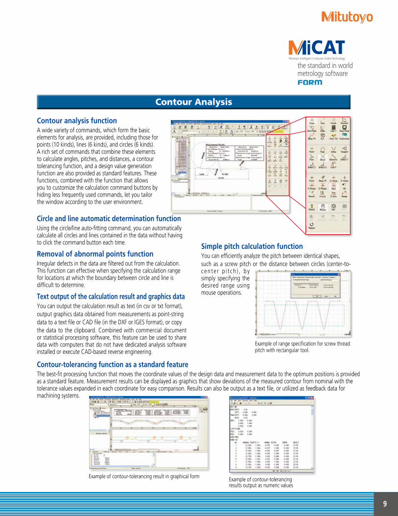
Circle and line automatic determination functionUsing the circle/line auto-fitting command, you can automaticallycalculate all circles and lines contained in the data without havingto click the command button each time.
Removal of abnormal points functionIrregular defects in the data are filtered out from the calculation. This function can effective when specifying the calculation range for locations at which the boundary between circle and line is difficult to determine.
Text output of the calculation result and graphics dataYou can output the calculation result as text (in csv or txt format),output graphics data obtained from measurements as point-stringdata to a text file or CAD file (in the DXF or IGES format), or copythe data to the clipboard. Combined with commercial document or statistical processing software, this feature can be used to share data with computers that do not have dedicated analysis software installed or execute CAD-based reverse engineering.
Contour analysis functionA wide variety of commands, which form the basicelements for analysis, are provided, including those forpoints (10 kinds), lines (6 kinds), and circles (6 kinds).A rich set of commands that combine these elementsto calculate angles, pitches, and distances, a contourtolerancing function, and a design value generationfunction are also provided as standard features. Thesefunctions, combined with the function that allowsyou to customize the calculation command buttons byhiding less frequently used commands, let you tailorthe window according to the user environment.
Simple pitch calculation functionYou can efficiently analyze the pitch between identical shapes,such as a screw pitch or the distance between circles (center-to-c e n t e r p i t c h ) , b y simply specifying the desired range using mouse operations.
Example of range specification for screw threadpitch with rectangular tool.
Contour-tolerancing function as a standard featureThe best-fit processing function that moves the coordinate values of the design data and measurement data to the optimum positions is provided as a standard feature. Measurement results can be displayed as graphics that show deviations of the measured contour from nominal with the tolerance values expanded in each coordinate for easy comparison. Results can also be output as a text file, or utilized as feedback data for machining systems.
Contour Analysis
Example of contour-tolerancing result in graphical form Example of contour-tolerancingresults output as numeric values

10
Contour Analysis Software: FORMTRACEPAK
Contour Analysis
Data combine
Data 2Data 1
Design value generation functionYou can generate design data from CAD data (DXF or IGES file) or text data. Furthermore, since you can also convertmeasurement data into design data, you can save parts data prior to use (testing) as design data and effectively utilize itfor checking the wear following use (testing).
Data combination functionYou can combine partial data collected separately from a work-piece (made necessary due to shape characteristics) into a single graphic for convenient analysis.
Calculation command repetition settingWhen identical shapes have the same pitch, you can analyze all ofthe shapes in a batch by specifying a single analysis location andthe pitch.
Best-fit processing function for measurementpoint stringsThis function tries to fit the measurement points to the stored reference data on the same coordinate system. It can eliminate the effects of a shift that may occur when setting the workpiece during automatic analysis.
Data superimposition commandYou can superimpose two sets of data by detecting their charac-teristic points. Use the mouse to drag and move the measurement point strings to the desired positions to be superimposed.

11
Integrated layout
You can use simple operations to lay out graphics obtained from measurements as well as measure-ment results for surface roughness, contour, and roundness on a single page.Furthermore, since the program now allows you to specify a saved file and paste it, you can easily paste results from multiple files.Note: the optional ROUNDPAK roundness/cylindricity analysis program is required. (Ver. 7 or higher)
Element information barThis bar displays the attribute values of the pasted items, allowing you to easily check the contents of the pasted measurement data files.
System layout printingBy simply selecting the items to be output, you can automatically lay out the page to be printed.Use this feature when you wish to simplify the printing task.
Element insertion barUsing the mouse to drag and drop the analysis content displayed in the element insertion bar, you can paste it into the layout. From the contour analysis result, you can also select the analysis result for a circle or line alone and paste it in position.
Saving the result as a web pageSince you can save the result in html or mhtml format, which can be displayed using Internet Explorer or Microsoft Word, you can check the result even on a PC on which no layout-editing program is installed.
Report creation functionYou can freely assemble measurement results/conditions/graphics as well as comments/circles/lines/arrows, and print them out in a measurementresult report. Furthermore, since you can paste bitmap files, you can also add a workpiece image or company logo to the layout.You can also save the created layout and use it again later for similar measurements.

12
Optional Accessories
3-axis Adjustment Table: 178-047
Table and fixture systems
This table helps make the adjustments required when measuring cylindrical surfaces. The corrections for the pitch angle and the swivel angle are determined from a preliminary measurement and the Digimatic micrometers are adjusted accordingly. A flat-surfaced workpiece can also be leveled with this table. By using Mitutoyo’s 3-axis adjustment table, the workpiece can be aligned and leveled easily, simply by following the FORMTRACEPAK guidance. No experience or special expertise is required.
Aligned Not Aligned
Path traced by stylus
End point
Path traced by stylus
End point
Start pointStart point
Recordedprofiles
Guidance display when using 3-axis adjustment table
Rotary vise218-003
V-block998291
Precision vise178-019
Cross-travel table218-001 (mm), 218-011 (inch)
Cross-travel table218-041 (mm), 218-051 (inch)
V-block with clamp172-234, 172-378
Holder with clamp176-107
Swivel center support172-197
Center support riser172-143
Center support172-142
Leveling table178-043-1 (mm), 178-053-1 (inch)
Digital Leveling table178-042-1 (mm), 178-052-1 (inch)
Leveling table178-016
Leveling table (for D.A.T.)178-016
Calibration stand*1
12AAG175
*1 Required for calibrating in bulk by mounting straight arm/small-hole stylus arm without using cross-travel table and Y-axis table.

13
Air Stand
64AAB357Vibration Isolation Stand
30" x 48" x 30"(762x1219x762mm)
178-024Stand for Desktop type
25.7”x18.5”x26.4”(640×470×670mm)
178-023Vibration isolatorManually charged
pneumatic type
178-025Vibration isolator
Automatically charged pneumatic type
Optional Accessories
17548 260
450600
8525
740
100
1751.89”(48) 10.23”(260)
45023.6”(600)
852529.1
”(74
0)
3.94
”(1
00)
.47”
(12)
218-042 Does not include (CV-2100N4)Vertical adjustment range: 12.6"(320mm)Inclination angle (MAX): ±45°Dimensions (W×D×H) : 23.6"x17.7"x29.1"(600×450×740mm)Mass: 242 lbs (110 kg)
Unit: inch (mm)
Example combination: with monitor arm butno side table*2 (tester and PC not included)
Vibration isolators (Desk types)
Manual column stand for CV-2100N4 Vibration isolators (Desktop types), floor stand and tables
Example combination: with a side table (tester and PC not included)
* Quick-vertical-motion function is not available
Desk type12AAK110
Monitor arm*1
12AAK120
Side table*2
12AAL019
*1 Used together with vibration isolator (12AAK110).*2 User to provide a printer rack.
Desk types

14
Arms and Stylus
15155
H
ø8
15
40155
H
φ8
Tip shape: One-sided cut (Tip Angle: 20°)Tip shape: Cone(Tip Angle: 30°)Tip radius: 25µmTip Material: Carbide
5040
ø8
ø42.5
h
Tip shape: One-sided cut (Tip Angle: 20°)Tip shape: Cone(Tip Angle: 30°)Tip radius: 25µmTip Material: Carbide
5020
ø6
ø31
h
Tip shape: One-sided cut (Tip Angle: 20°)Tip shape: Cone(Tip Angle: 30°)Tip radius: 25µmTip Material: Carbide
5012.5
ø6
ø1.60.4
h
25145
95H
ø8
One-sided cut stylus Intersecting cut stylus
Cone stylus Cone stylus
Knife-edge stylus Ball stylus
For small-hole stylus SP-11/31 For small-hole stylus SP-12/32
For small-hole stylus SP-13/33
Straight arm Eccentric arm
For small hole
Tip Angle: 12°Tip radius: 25µmTip Material: Carbide
ø3
h Tip Angle: 20°Tip radius: 25µmTip Material: Carbide
ø3
h
Tip Angle: 20°Tip radius: 25µmTip Material: Carbide
ø3
h Tip Angle: 30° (SPH-79 : 50°)Tip radius: 25µmTip Material: Sapphire·Carbide(SPH-79: Diamond)
ø3
h
Tip Angle: 20°Tip radius: 25µmEdge width: 3mmTip Material: Carbide
ø3
h
Tip radius: 1mmTip Material: Carbide
h
ø3
ø8
H
15155
40 stylus
* Select an arm and stylus that match the type of measurement you require.Type of arm Arm No. Part No. Adaptation stylus No. H: Inch (mm)AB-51 935111 SPH-51,52,53,54,55,56,57 .24"(6)
Straight armAB-61 935112 SPH-61,62,63,64,65,66,67 .48"(12)AB-71* 935113 SPH-71,72,73,74,75,76,77,79 .79"(20)AB-81 935114 SPH-81,82,83,84,85,86,87 1.19"(30)AB-91 935115 SPH-91,92,93,94,95,96,97 1.66"(42)AB-52 935116 SPH-51,52,53,54,55,56,57 .24"(6)AB-62 935117 SPH-61,62,63,64,65,66,67 .48"(12)
Eccentric arm AB-72 935118 SPH-71,72,73,74,75,76,77,79 .79"(20)AB-82 935119 SPH-81,82,83,84,85,86,87 1.19"(30)AB-92 935120 SPH-91,92,93,94,95,96,97 1.66"(42)
SP-11,31 .016"(0.4)For small hole AB-11 935110 SP-12,32 .04"(1)
SP-13,33 .1"(2.5)
*Standard accessory
Type of stylus Stylus No. Part No. Adaptation arm No. H: Inch (mm)SPH-51 354882 AB-51·52 .55"(14)SPH-61 354883 AB-61·62 .79"(20)
One-sided cut stylus SPH-71* 354884 AB-71·72 1.10"(28)SPH-81 345885 AB-81·82 1.5"(38)SPH-91 354886 AB-91·92 1.97"(50)SPH-52 354887 AB-51·52 .55"(14)SPH-62 354888 AB-61·62 .79"(20)
Intersecting cut stylus SPH-72 354889 AB-71·72 1.10"(28)SPH-82 354890 AB-81·82 1.5"(38)SPH-92 354891 AB-91·92 1.97"(50)SPH-57 12AAE865 AB-51·52 .55"(14)
Cone stylus SPH-67 12AAE866 AB-61·62 .79"(20)Tip angle 20° SPH-77 12AAE867 AB-71·72 1.10"(28)(Carbide) SPH-87 12AAE868 AB-81·82 1.5"(38)
SPH-97 12AAE869 AB-91·92 1.97"(50)SPH-53 354892 AB-51·52 .55"(14)
Cone stylus SPH-63 354893 AB-61·62 .79"(20)Tip angle 30° SPH-73 354894 AB-71·72 1.10"(28)(Sapphire) SPH-83 354895 AB-81·82 1.5"(38)
SPH-93 354896 AB-91·92 1.97"(50)Cone stylusTip angle 50° SPH-79 355129 AB-71·72 1.10"(28)(diamond)
SPH-56 12AAA566 AB-51·52 .55"(14)Cone stylus SPH-66 12AAA567 AB-61·62 .79"(20)Tip angle 30° SPH-76 12AAA568 AB-71·72 1.10"(28)(Carbide) SPH-86 12AAA569 AB-81·82 1.5"(38)
SPH-96 12AAA570 AB-91·92 1.97"(50)SPH-54 354897 AB-51·52 .55"(14)
Knife-edge stylusSPH-64 354898 AB-61·62 .79"(20) SPH-74 354899 AB-71·72 1.10"(28)SPH-84 354900 AB-81·82 1.5"(38)SPH-94 354901 AB-91·92 1.97"(50)SPH-55 354902 AB-51·52 .55"(14)
Ball stylusSPH-65 354903 AB-61·62 .79"(20)SPH-75 354904 AB-71·72 1.10"(28) SPH-85 354905 AB-81·82 1.5"(38)SPH-95 354906 AB-91·92 1.97"(50)
For small-hole stylus(One-sided cut)
SP-11 932693 AB-11 .08"(2)SP-12 932694 AB-11 .16"(4)SP-13 932695 AB-11 .26"(6.5)
For small-hole stylus(Cone)
SP-31 12AAE873 AB-11 .08"(2)SP-32 12AAE874 AB-11 .16"(4)SP-33 12AAE875 AB-11 .26"(6.5)
*Standard accessory
Arms (option)
Styli (option)

15
.47”
(12)
3.94
”(1
00)
5.7”(145)
2.76
”(70
)13
.8”(
350)
3.27”(83)
3.94”(100)
10.1”(257)
9.8”(250) (X=1.97”(50) Position)
13.7”(348.5)5.
45”
(138
.5)
30.4
”(77
3)34
.8”(
885)
17.7”(450)
3.35”(85)
5.65”(143.5) 6.89”(175)
1.73”(44)
4.76”(121)
3.92”(99.5)
23.6”(600)
Measuring area T-groove dimensions (CV-2100M4)
.59”(15)
.59”
(15).3”(8)
.3”(
8)
Specifications
Specifications
Dimensions
CV-2100M4 Unit: inch(mm)CV-2100N4
23.7”(601)
(79)
(34)(44)
44
809
234 57
13.7”(348.5)9.84”(250) (X=1.97”(50) Position)
2.87
”(7
3)
5.6”(143)
.78”(20) 1.73”(44)
5.45
”(1
38.5
)
1.36
”(34
.5) (
Z=0
Posit
ion)
6522050
.47”
(ø12
)
Model CV-2100M4 CV-2100N4Order No. 218-643A 218-623A
Measurement rangeX-axis 4"(100mm)Z1-axis (detector unit) 2"(50mm)
Z2-axis (column) travel range 13.8"(350mm) —X-axis inclination angle ±45° —
ResolutionX-axis 3.93μin (0.1μm)Z1-axis 3.93μin (0.1μm)
Drive methodX-axis Motorized drive 0 - 0.79in/s (0 - 20mm/s)Z2-axis (column) Manual (quick-up-and-down motion, fine feed) —
Measuring speed 0.00078 - 0.2in/sec (0.02 - 5mm/s)Linearity accuracy (X-axis horizontal orientation) 98.4μin/4in (2.5μm/100mm)
Accuracy (20°C)
X-axis ±(100+20L) μin [±(2.5+0.02L) μm)] L = Measurement Length (mm)Z1-axis ±(100+|100H|μin) [±(2.5+|0.1H|) μm] H = Measurementt height from horizontal position within 1"(±25mm)
Measurement direction Push and pullMeasurement surface direction DownwardMeasuring force (3gf) (30±10mN)Stylus traceable angle (Standard accessory stylus) Ascent 77°, Descent 87° (Depends on the surface condition)External dimensions (W×D×H) 29.3"x17.7"x34.8" (745×450×885mm) 25.6"x5.63"x5.45" (651×143×138.5mm)Mass 321.43 lbs (145.8 kg) 12.78 lbs (5.8 kg)

2.5M – 1213-04 Printed in USA, Aug. 2018
Whatever your challenges are, Mitutoyo supports you from start to finish.
Mitutoyo is not only a manufacturer of top-quality measuring products but one that also offers qualified support for the lifetime of the equipment, backed by comprehensive services that ensure your staff can make the very best use of the investment.
Apart from the basics of calibration and repair, Mitutoyo offers product and metrology training, as well as IT support for the sophisticated software used in modern measuring technology. We can also design, build, test and deliver measuring solutions and even, if deemed cost-effective, take your critical measurement challenges in-house on a sub-contract basis.
Coordinate Measuring Machines
Sensor Systems
Vision Measuring Systems
Test Equipment and Seismometers
Form Measurement
Digital Scale and DRO Systems
Optical Measuring
Small Tool Instruments and Data Management
Mitutoyo America Corporationwww.mitutoyo.comOne Number to Serve You Better1-888-MITUTOYO (1-888-648-8869)
M3 Solution Centers:Aurora, Illinois (Headquarters)Boston, MassachusettsCharlotte, North CarolinaCincinnati, OhioDetroit, MichiganLos Angeles, CaliforniaBirmingham, AlabamaSeattle, WashingtonHouston, Texas
© 2
018
Mitu
toyo
Am
erica
Cor
pora
tion
Find additional product literature and our product catalog
www.mitutoyo.com
Note: All information regarding our products, and in particular the illustrations, drawings, dimensional and performance data contained in this printed matter as well as other technical data are to be regarded as approximate average values. We therefore reserve the right to make changes to the corresponding designs. The stated standards, similar technical regulations, descriptions and illustrations of the products were valid at the time of printing. In addition, the latest applicable version of our General Trading Conditions will apply. Only quotations submitted by ourselves may be regarded as definitive. Specifications are subject to change without notice.
Mitutoyo products are subject to US Export Administration Regulations (EAR). Re-export or relocation of our products may require prior approval by an appropriate governing authority.
Trademarks and RegistrationsDesignations used by companies to distinguish their products are often claimed as trademarks. In all instances where Mitutoyo America Corporation is aware of a claim, the product names appear in initial capital or all capital letters. The appropriate companies should be contacted for more complete trademark and registration information.