CONTRA-RECUOS DENFLEX NVD - Uptech Brasil · CONTRA-RECUOS DISCFLEX EMBREAGENS INDUSTRIAIS FLEXOMAX...
46
2009/01 ACOPLAMENTO HIDRODINÂMICO CONTRA-RECUOS DISCFLEX EMBREAGENS INDUSTRIAIS FLEXOMAX G FLEXOMAX GBN FLEXOMAX GSN PINOFLEX - NP SPEFLEX - N VULBRAFLEX VB VULKARDAN - E VUL-MEX DENFLEX NVD
Transcript of CONTRA-RECUOS DENFLEX NVD - Uptech Brasil · CONTRA-RECUOS DISCFLEX EMBREAGENS INDUSTRIAIS FLEXOMAX...

2009/01
ACOPLAMENTO HIDRODINÂMICOCONTRA-RECUOS
DISCFLEXEMBREAGENS INDUSTRIAISFLEXOMAX GFLEXOMAX GBNFLEXOMAX GSNPINOFLEX - NPSPEFLEX - NVULBRAFLEX VBVULKARDAN - EVUL-MEX
DENFLEX NVD
01
MISCELLANEOUS
DENFLEX NVD
GENERALIDADES
São acoplamentos cuja transmisão de torquese dá através de denteado interno e externo.A geometria abaulada do denteado externo(cubo) permite uma articulação com odenteado interno (capa). A combinação deduas articulações confere ao acoplamento
a capacidade de compensartodos os tipos de desalinhamentos emoperação, bem como os desalinhamentosinevitáveis na instalação das máquinasacopladas.Por serem torcionalmente rídigos, osacoplamentos sãoespecialmente destinados às aplicações comnecessidade de sincronismo torcional,
DENFLEX NVD
DENFLEX NVD
ambientes agressivos a elastômeros(borracha, poliuretano, etc.), ou reversõesconstantes em carga.Os acoplamentos são con-feccionados em aço beneficiado, totalmenteusinados e conectados com parafusos de altaresistência, de modo a possuírem elevadacapacidade de transmissão em relaçãotamanho/peso e maior confiabilidade quantoà resistência a esforços ocasionais elevados(choques).Os flanges de união entre as capas dosacoplamentos tem dimen-sões conforme norma AGMA 516.01, sendoportanto, intercambiáveis com a maioria dos
DENFLEX NVD
DENFLEX NVD
acoplamentos de engrenagem.São adequados para trabalho em ambientescom temperatura entre -10ºC e + 90ºC, comlubrificação por graxa. Maiores detalhes vide“LUBRIFICAÇÃO” (pág. 43).Estão disponíveis em várias formasconstrutivas para atender a cada necessida-de com facilidade de manuseio e montagem.Os acoplamentos são forne-cidos com película de cera anticorrosiva paraproteção superifical.Em caso de dúvidas ou necessidades deacoplamentos especiais, favor consultar-nos.
DENFLEX NVD
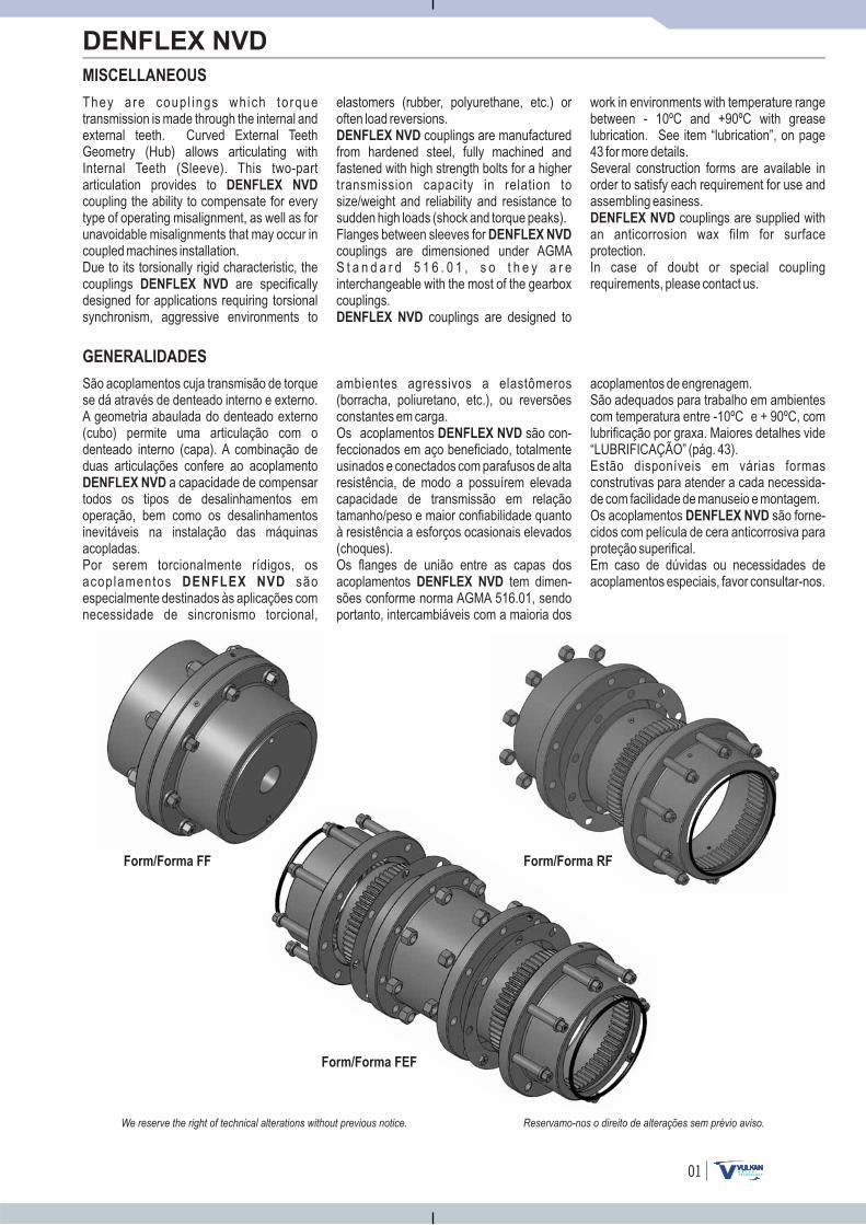
Form/Forma FEF
Form/Forma RFForm/Forma FF
They are coup l ings which torquetransmission is made through the internal andexternal teeth. Curved External TeethGeometry (Hub) allows articulating withInternal Teeth (Sleeve). This two-partarticulation provides tocoupling the ability to compensate for every
of operating misalignment, as well as forunavoidable misalignments that may occur incoupled machines installation.
DENFLEX NVD
are specificallyfor applications requiring
synchronism, aggressive environments
type
Due to its torsionally rigid characteristic, thecouplingsdesigned torsional
to
DENFLEX NVD
elastomers (rubber, polyurethane, etc.) oroften load reversions.DENFLEX NVD
DENFLEX NVD
DENFLEX NVD
couplings are manufacturedfrom hardened steel, fully machined andfastened with high strength bolts for atransmission capacity in relation tosize/weight and reliability and resistance tosudden high loads (shock and torque peaks).Flanges between sleeves forcouplings are dimensioned under AGMAS t a n d a r d 5 1 6 . 0 1 , s o t h e y a r einterchangeable with the most of thecouplings.
couplings are
higher
gearbox
designed to
work in environments temperature rangebetween - 10ºC and +90ºC with greaselubrication. See item “lubrication”, on page43 for more details.Several construction forms are available inorder to satisfy each requirement for use andassembling easiness.
couplings are supplied withan anticorrosion wax film for surfaceprotection.In case of doubt or special couplingrequirements, please contact us.
DENFLEX NVD
with
Reservamo-nos o direito de alterações sem prévio aviso.We reserve the right of technical alterations without previous notice.
02
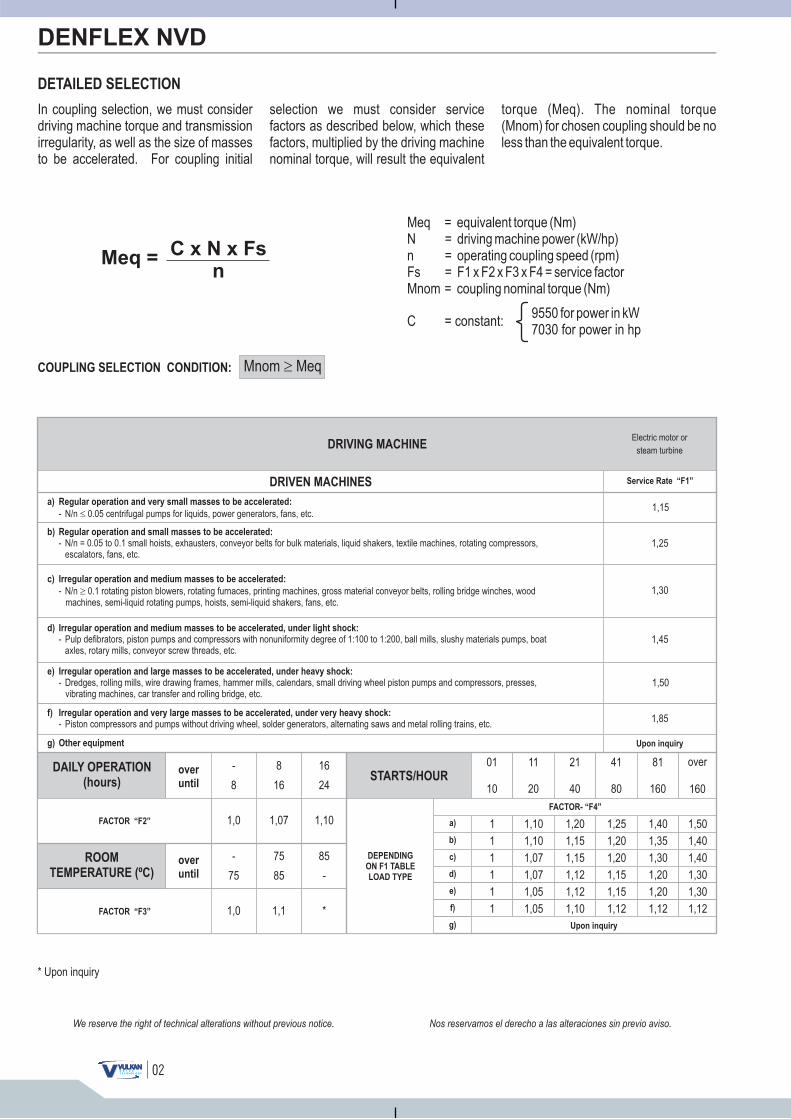
DETAILED SELECTION
DENFLEX NVD
Meq =N =n =Fs = F1 x F2 x F3 x F4 =Mnom =
equivalent torque (Nm)driving machine power (kW/hp)operating coupling speed (rpm)
service factorcoupling nominal torque (Nm)
Meq =C x N x Fs
n
9550 for power in kW7030 for power in hp
C = constant:
COUPLING SELECTION CONDITION: Mnom Meq�
DRIVING MACHINEElectric motor or
steam turbine
DRIVEN MACHINES Service Rate “F1”
1,15
1,25
1,30
1,45
1,50
1,85
DAILY OPERATION
(hours)
ROOM
TEMPERATURE (ºC)
FACTOR “F2”
FACTOR “F3”
over
until
over
until
-
8
1,0
-
75
1,0
8
16
1,07
75
85
1,1
16
24
01
10
11
20
21
40
41
80
81
160
over
160
1,10
85
-
*
STARTS/HOUR
DEPENDING
ON F1 TABLE
LOAD TYPE
FACTOR- “F4”
a)
b)
c)
d)
e)
f)
g)
1 1,10 1,20 1,25 1,40 1,50
1 1,10 1,15 1,20 1,35 1,40
1 1,07 1,15 1,20 1,30 1,40
1 1,07 1,12 1,15 1,20 1,30
1 1,05 1,12 1,15 1,20 1,30
1 1,05 1,10 1,12 1,12 1,12Upon inquiry
* Upon inquiry
Nos reservamos el derecho a las alteraciones sin previo aviso.We reserve the right of technical alterations without previous notice.
In coupling selection, we must considerdriving machine torque and transmissionirregularity, as well as the size of massesto be accelerated. For coupling initial
selection we must consider servicefactors as described below, which thesefactors, multiplied by the driving machinenominal torque, will result the equivalent
torque (Meq). The nominal torque(Mnom) for chosen coupling should be noless than the equivalent torque.
a) Regular operation and very small masses to be accelerated:
- N/n 0.05 centrifugal pumps for liquids, power generators, fans, etc.�
b) Regular operation and small masses to be accelerated:
- N/n = 0.05 to 0.1 small hoists, exhausters, conveyor belts for bulk materials, liquid shakers, textile machines, rotating compressors,escalators, fans, etc.
c) Irregular operation and medium masses to be accelerated:
- N/n 0.1 rotating piston blowers, rotating furnaces, printing machines, gross material conveyor belts, rolling bridge winches, woodmachines, semi-liquid rotating pumps, hoists, semi-liquid shakers, fans, etc.
�
d) Irregular operation and medium masses to be accelerated, under light shock:
- Pulp defibrators, piston pumps and compressors with nonuniformity degree of 1:100 to 1:200, ball mills, slushy materials pumps, boataxles, rotary mills, conveyor screw threads, etc.
e) Irregular operation and large masses to be accelerated, under heavy shock:
- Dredges, rolling mills, wire drawing frames, hammer mills, calendars, small driving wheel piston pumps and compressors, presses,vibrating machines, car transfer and rolling bridge, etc.
f) Irregular operation and very large masses to be accelerated, under very heavy shock:
- Piston compressors and pumps without driving wheel, solder generators, alternating saws and metal rolling trains, etc.
g) Other equipment Upon inquiry

03
DENFLEX NVD
Reservamo-nos o direito de alterações sem prévio aviso.We reserve the right of technical alterations without previous notice.
SELEÇÃO DETALHADA
Na seleção de um acoplamento é imprescindível considerar os momentos da máquina acionadora e o grau de irregularidade do sistema, como também a magnitude das massas a serem
aceleradas. Para determinação inicial do acoplamento é necessário considerar os fatores de serviço descritos abaixo, os quais multiplicados ao momento nominal da máquina acionadora, determinarão o
momento equivalente (Meq). O momento nominal (Mnom) do acoplamento escolhido deverá ser maior ou igual ao momento equivalente.
Meq = momento equivalente (Nm)N = potência da máquina acionadora (kW/ cv)n = rotação de trabalho do acoplamento (rpm)Fs = F1 x F2 x F3 x F4 = fator de serviçoMnom = momento nominal do acoplamento (Nm)
Meq = C x N x Fsn
9550 para potência em kW7030 para potência em cv
C = constante:
CONDIÇÃO PARA ASELEÇÃO DE UM ACOPLAMENTO: Mnom Meq
MÁQUINA ACIONADORAMotor elétrico ou
turbina a vapor
MÁQUINAS ACIONADAS Fator de Serviço - “F1”
a) Com serviço regular e reduzidas massas a acelerar:- Bombas centrífugas para líquidos, geradores elétricos, ventiladores com N/n 0,05, etc.
b) Com serviço regular e pequenas massas a acelerar:- Pequenos elevadores, exaustores, correias transportadoras para materiais a granel, agitadores para líquidos, máquinas têxteis, compressores
rotativos, escadas rolantes, ventiladores com N/n = 0,05 a 0,1, etc.
c) Com serviço irregular e médias massas a acelerar:- Sopradores de êmbolo rotativo, fornos giratórios, máquinas impressoras, correias transportadoras para materiais brutos, guinchos de pontes
rolantes, máquinas para madeira, bombas rotativas para semi-líquidos, elevadores de carga, agitadores para semi-líquidos, ventiladores com N/n 0,1, etc.
d) Com serviço irregular e médias massas a acelerar, com choques leves:- Desfibradores de polpa, bombas e compressores de êmbolo com grau de desuniformidade de 1:100 à 1: 200, moinhos de bolas, bombas para substâncias
pastosas, eixos de barcos, moinhos centrífugos, roscas transportadoras, etc.
e) Com serviço irregular e grandes massas a acelerar, com choques fortes:- Dragas, laminadores, trefiladores de arames, moinhos de martelo, calandras, bombas e compressores de êmbolo com volante pequeno, prensas,
máquinas vibradoras, translação de carro e ponte rolante, etc.
f) Com serviço irregular e massas muito grandes a acelerar, com choques muito fortes:- Compressores e bombas de êmbolo sem volante, geradores de solda, serras alternativas e trens de laminação de metais, etc.
g) Outros equipamentos Sob consulta
1,15
1,25
1,30
1,45
1,50
1,85
FUNCIONAMENTODIÁRIO (horas)
TEMPERATURAAMBIENTE (ºC)
FATOR - “F2”
FATOR - “F3”
mais deaté
mais deaté
-
8
1,0
-
75
1,0
8
16
1,07
75
85
1,1
16
24
01
10
11
20
21
40
41
80
81
160
acimade160
1,10
85
-
*
PARTIDAS/HORA
EM FUNÇÃODO TIPO DECARGA DA
TABELA DE F1
FATOR - “F4”
a)
b)
c)
d)
e)
f)
g)
1 1,10 1,20 1,25 1,40 1,50
1 1,10 1,15 1,20 1,35 1,40
1 1,07 1,15 1,20 1,30 1,40
1 1,07 1,12 1,15 1,20 1,30
1 1,05 1,12 1,15 1,20 1,30
1 1,05 1,10 1,12 1,12 1,12
Sob consulta
* Sob consulta
04
8000
6500
5600
5000
4400
3900
3600
3200
2900
2650
2450
2150
1750
1550
1450
1330
1200
(1)
4,0
9,1
15
27
41
65
97
132
193
256
312
500
680
950
1220
1590
2040
0,0054
0,0204
0,0450
0,1113
0,2098
0,4667
0,8856
1,4399
2,7284
4,2146
5,6461
12,0638
15,7200
27,8300
41,3300
63,4200
98,1900
3,9
9,0
14
27
40
61
95
130
190
230
300
470
680
940
1250
1620
2070
0,0052
0,0197
0,0414
0,1070
0,2015
0,4388
0,8460
1,3686
2,6048
3,8940
5,1480
11,1440
18,6500
32,5400
50,9200
75,8900
117,1000
0,0097
0,0356
0,0722
0,1791
0,3246
0,7112
1,3007
2,0027
3,9857
5,8523
6,5707
14,6859
DENFLEX NVD
SIZE
TAMANHO
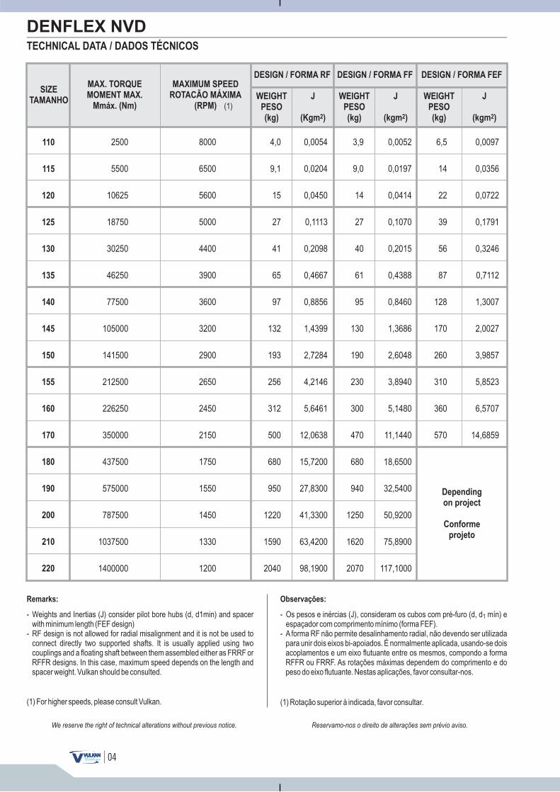
TECHNICAL DATA / DADOS TÉCNICOS
110
115
120
125
130
135
140
145
150
155
160
170
180
190
200
210
220
DESIGN / FORMA RF
WEIGHT
PESO
(kg)
J
(Kgm )2
DESIGN / FORMA FF
WEIGHT
PESO
(kg)
WEIGHT
PESO
(kg)
J
(kgm )2
J
(kgm )2
DESIGN / FORMA FEF
Depending
on project
Conforme
projeto
Observações:
- Os pesos e inércias (J), consideram os cubos com pré-furo (d, d mín) eespaçador com comprimento mínimo (forma FEF).
- A forma RF não permite desalinhamento radial, não devendo ser utilizadapara unir dois eixos bi-apoiados. É normalmente aplicada, usando-se doisacoplamentos e um eixo flutuante entre os mesmos, compondo a formaRFFR ou FRRF. As rotações máximas dependem do comprimento e dopeso do eixo flutuante. Nestas aplicações, favor consultar-nos.
1
(1) Rotação superior à indicada, favor consultar.
6,5
14
22
39
56
87
128
170
260
310
360
570
Remarks:
- Weights and Inertias (J) consider pilot bore hubs (d, d1min) and spacerwith minimum length (FEF design)
- RF design is not allowed for radial misalignment and it is not be used toconnect directly two supported shafts.
FRRF orRFFR designs. In this case, maximum speed depends on the length andspacer weight. Vulkan should be consulted.
It is usually applied using twocouplings and a floating shaft between them assembled either as
(1) For higher speeds, please consult Vulkan.
Reservamo-nos o direito de alterações sem prévio aviso.We reserve the right of technical alterations without previous notice.
MAX. TORQUE
MOMENT MAX.
Mmáx. (Nm)
2500
5500
10625
18750
30250
46250
77500
105000
141500
212500
226250
350000
437500
575000
787500
1037500
1400000
MAXIMUM SPEED
ROTACÃO MÁXIMA
(RPM)

05
FORM/FORMA FLF
FORM/FORMA FF
FORM/FORMA FF1I
FORM/FORMA FF2I
FORM/FORMA FF1L
FORM/FORMA FF1IL
Coupling formed by two standard toothed hubs and a continuous toothed sleeve (without screw). Indicated forhorizontal operation. It allows radial, axial, and angular misalignment.
Acoplamento composto por dois cubos dentados padrão e uma capa lisa dentada (sem aparafusamento). Indicadopara serviço horizontal. Admite desalinhamentos radial, axial e angular.
Acoplamento composto por dois cubos dentados padrão e duas capas dentadas padrão, sendo as duas capasaparafusadas e os dois cubos montados na posição normal, proporcionando o menor espaçamento entre si.Indicado para serviço horizontal.Admite desalinhamentos radial, axial e angular.
Acoplamento composto por dois cubos dentados padrão, duas capas dentadas padrão, sendo as duas capasaparafusadas e um cubo montado na posição normal e um cubo montado na posição invertida, proporcionando umespaçamento médio entre si. Indicado para serviço horizontal. Admite desalinhamentos radial, axial e angular.
Acoplamento composto por dois cubos dentados padrão, duas capas dentadas padrão, sendo as duas capasaparafusadas e os dois cubos montados na posição invertida, proporcionando o maior espaçamento entre si.Indicado para serviço horizontal. Admite desalinhamentos radial, axial e angular.
Acoplamento composto por um cubo dentado padrão e um cubo dentado longo e duas capas dentadas padrão,sendo as duas capas aparafusadas e os dois cubos montados na posição normal, proporcionando umespaçamento médio entre si. Indicado para serviço horizontal.Admite desalinhamentos radial, axial e angular.
Acoplamento composto por um cubo dentado padrão e um cubo dentado longo e duas capas dentadas padrão,sendo o cubo padrão montado na posição invertida e o cubo longo na posição normal, proporcionando o maiorespaçamento entre si. Indicado para serviço horizontal.Admite desalinhamentos radial, axial e angular.
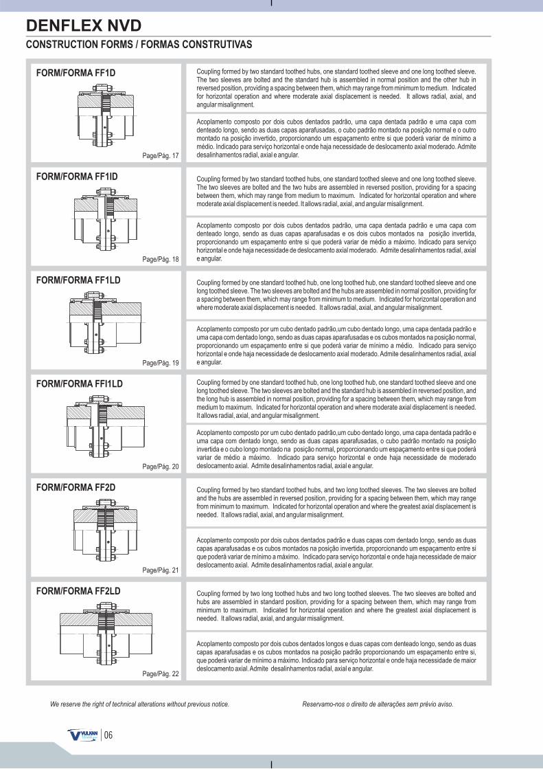
CONSTRUCTION FORMS / FORMAS CONSTRUTIVAS
DENFLEX NVD
FORM/FORMA FF2L
Acoplamento composto por dois cubos dentados longos e duas capas dentadas padrão, sendo as duas capasaparafusadas e os dois cubos longos montados na posição normal, proporcionando o maior espaçamento entre si.Indicado para serviço horizontal.Admite desalinhamentos radial, axial e angular.
Page/Pág. 10
Page/Pág. 11
Page/Pág. 12
Page/Pág. 13
Page/Pág. 14
Page/Pág. 15
Page/Pág. 16
Reservamo-nos o direito de alterações sem prévio aviso.We reserve the right of technical alterations without previous notice.
Coupling formed by two standard toothed hubs and two standard toothed sleeves. The two sleeves are bolted, onehub is assembled in normal position and other hub is assembled in reversed position, providing medium spacingbetween them. Indicated for horizontal operation. It allows radial, axial, and angular misalignment.
Coupling formed by two standard toothed hubs and two standard toothed sleeves. The two sleeves are bolted andhubs are assembled in normal position, providing the least spacing between them. Indicated for horizontaloperation. It allows radial, axial, and angular misalignment.
Coupling formed by two standard toothed hubs, two standard toothed sleeves. The two sleeves are bolted and hubsare assembled in reversed position, providing for the greatest spacing among them. Indicated for horizontaloperation. It allows radial, axial, and angular misalignment.
Coupling formed by one standard toothed hub and one long toothed hub, and two standard toothed sleeves. The twosleeves are bolted and hubs are assembled in normal position, providing a medium spacing between them.Indicated for horizontal operation. It allows for radial, axial and angular misalignment.
Coupling formed by one standard toothed hub and one long toothed hub, and two standard toothed sleeves. Thestandard hub is assembled in reversed position and the long hub in normal position, providing for the greatestspacing between them. Indicated for horizontal operation. It allows radial, axial, and angular misalignment.
Coupling formed by two long toothed hubs, and two standard toothed sleeves. The two sleeves are bolted and thetwo long hubs are assembled in normal position, providing for the greatest spacing them. Indicated forhorizontal operation. It allows radial, axial, and angular misalignment.
between
06
CONSTRUCTION FORMS / FORMAS CONSTRUTIVAS
Reservamo-nos o direito de alterações sem prévio aviso.
DENFLEX NVD
FORM/FORMA FF1D
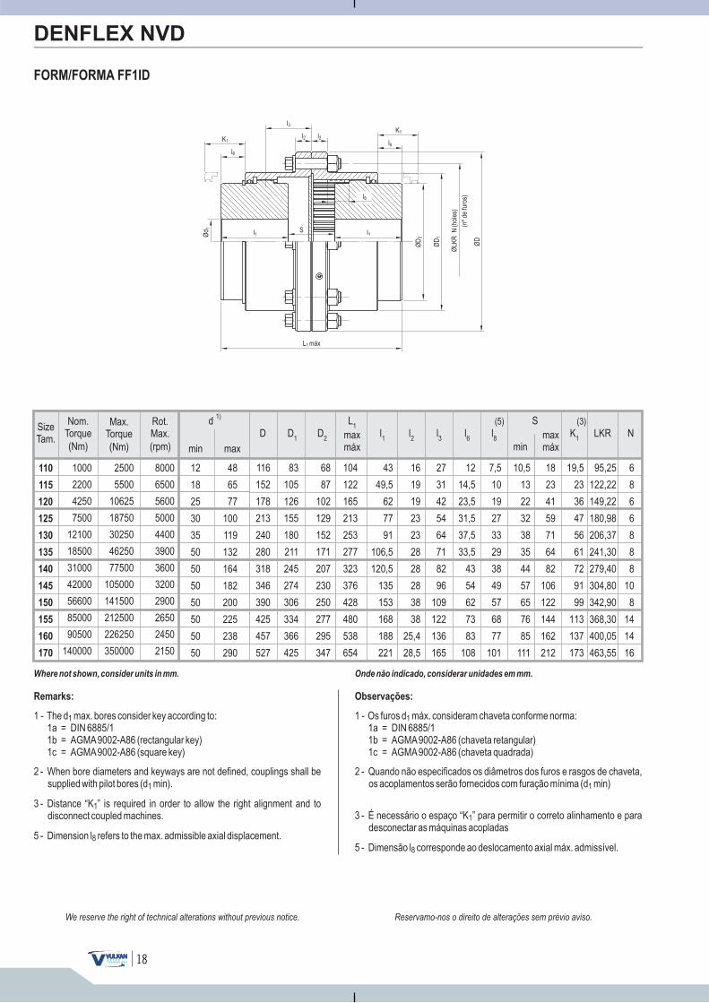
FORM/FORMA FF1ID
FORM/FORMA FF1LD
FORM/FORMA FFI1LD
Acoplamento composto por dois cubos dentados padrão, uma capa dentada padrão e uma capa comdenteado longo, sendo as duas capas aparafusadas, o cubo padrão montado na posição normal e o outromontado na posição invertido, proporcionando um espaçamento entre si que poderá variar de mínimo amédio. Indicado para serviço horizontal e onde haja necessidade de deslocamento axial moderado. Admitedesalinhamentos radial, axial e angular.
Acoplamento composto por dois cubos dentados padrão, uma capa dentada padrão e uma capa comdenteado longo, sendo as duas capas aparafusadas e os dois cubos montados na posição invertida,proporcionando um espaçamento entre si que poderá variar de médio a máximo. Indicado para serviçohorizontal e onde haja necessidade de deslocamento axial moderado. Admite desalinhamentos radial, axiale angular.
Acoplamento composto por um cubo dentado padrão,um cubo dentado longo, uma capa dentada padrão euma capa com dentado longo, sendo as duas capas aparafusadas, o cubo padrão montado na posiçãoinvertida e o cubo longo montado na posição normal, proporcionando um espaçamento entre si que poderávariar de médio a máximo. Indicado para serviço horizontal e onde haja necessidade de moderadodeslocamento axial. Admite desalinhamentos radial, axial e angular.
Acoplamento composto por um cubo dentado padrão,um cubo dentado longo, uma capa dentada padrão euma capa com dentado longo, sendo as duas capas aparafusadas e os cubos montados na posição normal,proporcionando um espaçamento entre si que poderá variar de mínimo a médio. Indicado para serviçohorizontal e onde haja necessidade de deslocamento axial moderado. Admite desalinhamentos radial, axiale angular.
FORM/FORMA FF2D
Acoplamento composto por dois cubos dentados padrão e duas capas com dentado longo, sendo as duascapas aparafusadas e os cubos montados na posição invertida, proporcionando um espaçamento entre sique poderá variar de mínimo a máximo. Indicado para serviço horizontal e onde haja necessidade de maiordeslocamento axial. Admite desalinhamentos radial, axial e angular.
FORM/FORMA FF2LD
Acoplamento composto por dois cubos dentados longos e duas capas com denteado longo, sendo as duascapas aparafusadas e os cubos montados na posição padrão proporcionando um espaçamento entre si,que poderá variar de mínimo a máximo. Indicado para serviço horizontal e onde haja necessidade de maiordeslocamento axial.Admite desalinhamentos radial, axial e angular.
Page/Pág. 17
Page/Pág. 18
Page/Pág. 19
Page/Pág. 20
Page/Pág. 21
Page/Pág. 22
We reserve the right of technical alterations without previous notice.
Coupling formed by two standard toothed hubs, one standard toothed sleeve and one long toothed sleeve.The two sleeves are bolted and the standard hub is assembled in normal position and the other hub inreversed position, providing a spacing between them, which may range from minimum to medium. Indicatedfor horizontal operation and where moderate axial displacement is needed. It allows radial, axial, andangular misalignment.
Coupling formed by one standard toothed hub, one long toothed hub, one standard toothed sleeve and onelong toothed sleeve. The two sleeves are bolted and the hubs are assembled in normal position, providing fora spacing between them, which may range from minimum to medium. Indicated for horizontal operation andwhere moderate axial displacement is needed. It allows radial, axial, and angular misalignment.
Coupling formed by two standard toothed hubs, one standard toothed sleeve and one long toothed sleeve.The two sleeves are bolted and the two hubs are assembled in reversed position, providing for a spacingbetween them, which may range from medium to maximum. Indicated for horizontal operation and wheremoderate axial displacement is needed. It allows radial, axial, and angular misalignment.
Coupling formed by one standard toothed hub, one long toothed hub, one standard toothed sleeve and onelong toothed sleeve. The two sleeves are bolted and the standard hub is assembled in reversed position, andthe long hub is assembled in normal position, providing for a spacing them, which may range frommedium to maximum. Indicated for horizontal operation and where moderate axial displacement is needed.It allows radial, axial, and angular misalignment.
between
Coupling formed by two standard toothed hubs, and two long toothed sleeves. The two sleeves are boltedand the hubs are assembled in reversed position, providing for a spacing between them, which may rangefrom minimum to maximum. Indicated for horizontal operation and where the greatest axial displacement isneeded. It allows radial, axial, and angular misalignment.
Coupling formed by two long toothed hubs and two long toothed sleeves. The two sleeves are bolted andhubs are assembled in standard position, providing for a spacing between them, which may range fromminimum to maximum. Indicated for horizontal operation and where the greatest axial displacement isneeded. It allows radial, axial, and angular misalignment.
07
CONSTRUCTION FORMS / FORMAS CONSTRUTIVAS
DENFLEX NVD
FORM/FORMA RF
FORM/FORMA RFI
FORM/FORMA RF1L
FORM/FORMA RFID
FORM/FORMA RF1LD
FORM/FORMA FEF
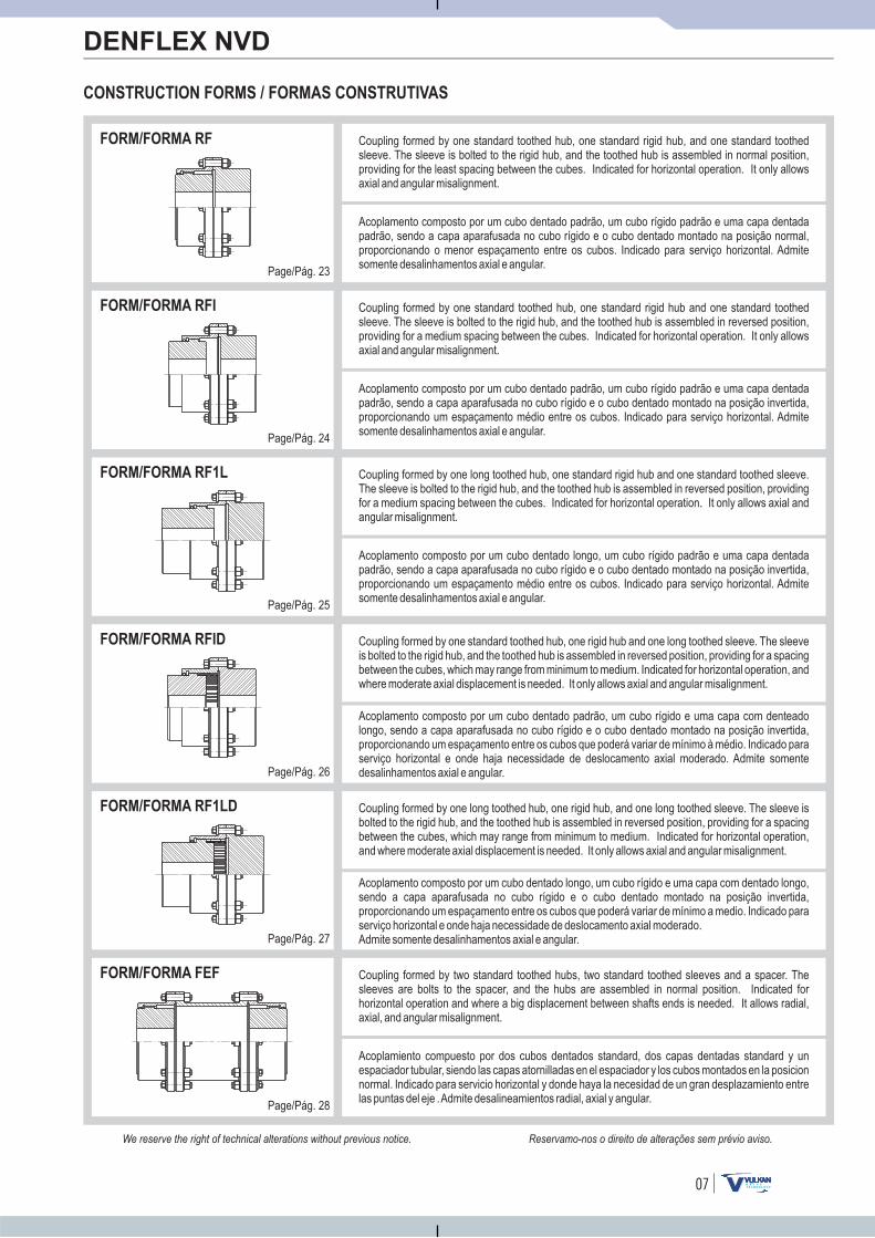
Acoplamento composto por um cubo dentado padrão, um cubo rígido padrão e uma capa dentadapadrão, sendo a capa aparafusada no cubo rígido e o cubo dentado montado na posição normal,proporcionando o menor espaçamento entre os cubos. Indicado para serviço horizontal. Admitesomente desalinhamentos axial e angular.
Acoplamento composto por um cubo dentado padrão, um cubo rígido padrão e uma capa dentadapadrão, sendo a capa aparafusada no cubo rígido e o cubo dentado montado na posição invertida,proporcionando um espaçamento médio entre os cubos. Indicado para serviço horizontal. Admitesomente desalinhamentos axial e angular.
Acoplamento composto por um cubo dentado longo, um cubo rígido padrão e uma capa dentadapadrão, sendo a capa aparafusada no cubo rígido e o cubo dentado montado na posição invertida,proporcionando um espaçamento médio entre os cubos. Indicado para serviço horizontal. Admitesomente desalinhamentos axial e angular.
Acoplamento composto por um cubo dentado padrão, um cubo rígido e uma capa com denteadolongo, sendo a capa aparafusada no cubo rígido e o cubo dentado montado na posição invertida,proporcionando um espaçamento entre os cubos que poderá variar de mínimo à médio. Indicado paraserviço horizontal e onde haja necessidade de deslocamento axial moderado. Admite somentedesalinhamentos axial e angular.
Acoplamento composto por um cubo dentado longo, um cubo rígido e uma capa com dentado longo,sendo a capa aparafusada no cubo rígido e o cubo dentado montado na posição invertida,proporcionando um espaçamento entre os cubos que poderá variar de mínimo a medio. Indicado paraserviço horizontal e onde haja necessidade de deslocamento axial moderado.Admite somente desalinhamentos axial e angular.
Acoplamiento compuesto por dos cubos dentados standard, dos capas dentadas standard y unespaciador tubular, siendo las capas atornilladas en el espaciador y los cubos montados en la posicionnormal. Indicado para servicio horizontal y donde haya la necesidad de un gran desplazamiento entrelas puntas del eje .Admite desalineamientos radial, axial y angular.
Page/Pág. 23
Page/Pág. 24
Page/Pág. 25
Page/Pág. 26
Page/Pág. 27
Page/Pág. 28
Reservamo-nos o direito de alterações sem prévio aviso.We reserve the right of technical alterations without previous notice.
Coupling formed by one standard toothed hub, one standard rigid hub, and one standard toothedsleeve. The sleeve is bolted to the rigid hub, and the toothed hub is assembled in normal position,providing for the least spacing between the cubes. Indicated for horizontal operation. It only allowsaxial and angular misalignment.
Coupling formed by two standard toothed hubs, two standard toothed sleeves and a spacer. Thesleeves are bolts to the spacer, and the hubs are assembled in normal position. Indicated forhorizontal operation and where a big displacement between shafts ends is needed. It allows radial,axial, and angular misalignment.
Coupling formed by one standard toothed hub, one rigid hub and one long toothed sleeve. The sleeveis bolted to the rigid hub, and the toothed hub is assembled in reversed position, providing for a spacingbetween the cubes, which may range from minimum to medium. Indicated for horizontal operation, andwhere moderate axial displacement is needed. It only allows axial and angular misalignment.
Coupling formed by one standard toothed hub, one standard rigid hub and one standard toothedsleeve. The sleeve is bolted to the rigid hub, and the toothed hub is assembled in reversed position,providing for a medium spacing between the cubes. Indicated for horizontal operation. It only allowsaxial and angular misalignment.
Coupling formed by one long toothed hub, one standard rigid hub and one standard toothed sleeve.The sleeve is bolted to the rigid hub, and the toothed hub is assembled in reversed position, providingfor a medium spacing between the cubes. Indicated for horizontal operation. It only allows axial andangular misalignment.
Coupling formed by one long toothed hub, one rigid hub, and one long toothed sleeve. The sleeve isbolted to the rigid hub, and the toothed hub is assembled in reversed position, providing for a spacingbetween the cubes, which may range from minimum to medium. Indicated for horizontal operation,and where moderate axial displacement is needed. It only allows axial and angular misalignment.
08
CONSTRUCTION FORMS / FORMAS CONSTRUTIVAS
DENFLEX NVD
FORM/FORMA FRRF
FORM/FORMA RFFR
FORM/FORMA FFV
FORM/FORMA RFV
FORM/FORMA RR
FORM/FORMA RRV
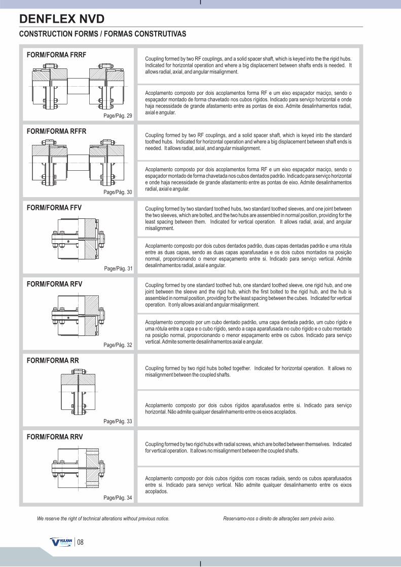
Acoplamento composto por dois acoplamentos forma RF e um eixo espaçador maciço, sendo oespaçador montado de forma chavetado nos cubos rígidos. Indicado para serviço horizontal e ondehaja necessidade de grande afastamento entre as pontas de eixo. Admite desalinhamentos radial,axial e angular.
Acoplamento composto por dois acoplamentos forma RF e um eixo espaçador maciço, sendo oespaçador montado de forma chavetada nos cubos dentados padrão. Indicado para serviço horizontale onde haja necessidade de grande afastamento entre as pontas de eixo. Admite desalinhamentosradial, axial e angular.
Acoplamento composto por dois cubos dentados padrão, duas capas dentadas padrão e uma rótulaentre as duas capas, sendo as duas capas aparafusadas e os dois cubos montados na posiçãonormal, proporcionando o menor espaçamento entre si. Indicado para serviço vertical. Admitedesalinhamentos radial, axial e angular.
Acoplamento composto por um cubo dentado padrão, uma capa dentada padrão, um cubo rígido euma rótula entre a capa e o cubo rígido, sendo a capa aparafusada no cubo rígido e o cubo montadona posição normal, proporcionando o menor espaçamento entre os cubos. Indicado para serviçovertical.Admite somente desalinhamentos axial e angular.
Acoplamento composto por dois cubos rígidos aparafusados entre si. Indicado para serviçohorizontal. Não admite qualquer desalinhamento entre os eixos acoplados.
Acoplamento composto por dois cubos rígidos com roscas radiais, sendo os cubos aparafusadosentre si. Indicado para serviço vertical. Não admite qualquer desalinhamento entre os eixosacoplados.
Page/Pág. 29
Page/Pág. 30
Page/Pág. 31
Page/Pág. 32
Page/Pág. 33
Page/Pág. 34
Reservamo-nos o direito de alterações sem prévio aviso.We reserve the right of technical alterations without previous notice.
Coupling formed by two RF couplings, and a solid spacer shaft, which is keyed into the the rigid hubs.Indicated for horizontal operation and where a big displacement between shafts ends is needed. Itallows radial, axial, and angular misalignment.
Coupling formed by two rigid hubs with radial screws, which are bolted between themselves. Indicatedfor vertical operation. It allows no misalignment between the coupled shafts.
Coupling formed by two rigid hubs bolted together. Indicated for horizontal operation. It allows nomisalignment between the coupled shafts.
Coupling formed by two standard toothed hubs, two standard toothed sleeves, and one joint betweenthe two sleeves, which are bolted, and the two hubs are assembled in normal position, providing for theleast spacing between them. Indicated for vertical operation. It allows radial, axial, and angularmisalignment.
Coupling formed by two RF couplings, and a solid spacer shaft, which is keyed into the standardtoothed hubs. Indicated for horizontal operation and where a big displacement between shaft ends isneeded. It allows radial, axial, and angular misalignment.
Coupling formed by one standard toothed hub, one standard toothed sleeve, one rigid hub, and onejoint between the sleeve and the rigid hub, which the first bolted to the rigid hub, and the hub isassembled in normal position, providing for the least spacing between the cubes. Indicated for verticaloperation. It only allows axial and angular misalignment.
01
CONSTRUCTION FORMS / FORMAS CONSTRUTIVAS
DENFLEX NVD
FORM/FORMA FFB
FORM/FORMA RFB
FORM/FORMA FFTB
FORM/FORMA RFTB
FORM/FORMA FFAR
FORM/FORMA FFAS
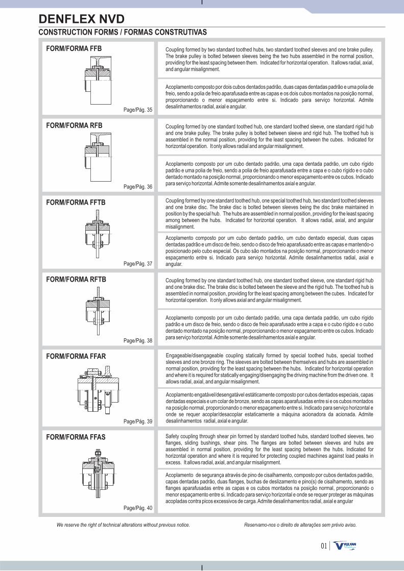
Acoplamento composto por dois cubos dentados padrão, duas capas dentadas padrão e uma polia defreio, sendo a polia de freio aparafusada entre as capas e os dois cubos montados na posição normal,proporcionando o menor espaçamento entre si. Indicado para serviço horizontal. Admitedesalinhamentos radial, axial e angular.
Acoplamento composto por um cubo dentado padrão, uma capa dentada padrão, um cubo rígidopadrão e uma polia de freio, sendo a polia de freio aparafusada entre a capa e o cubo rígido e o cubodentado montado na posição normal, proporcionando o menor espaçamento entre os cubos. Indicadopara serviço horizontal.Admite somente desalinhamentos axial e angular.
Acoplamento composto por um cubo dentado padrão, um cubo dentado especial, duas capasdentadas padrão e um disco de freio, sendo o disco de freio aparafusado entre as capas e mantendo-oposicionado pelo cubo especial. Os cubo são montados na posição normal, proporcionando o menorespaçamento entre si. Indicado para serviço horizontal. Admite desalinhamentos radial, axial eangular.
Acoplamento composto por um cubo dentado padrão, uma capa dentada padrão, um cubo rígidopadrão e um disco de freio, sendo o disco de freio aparafusado entre a capa e o cubo rígido e o cubodentado montado na posição normal, proporcionando o menor espaçamento entre os cubos. Indicadopara serviço horizontal.Admite somente desalinhamentos axial e angular.
Acoplamento de segurança através de pino de cisalhamento, composto por cubos dentados padrão,capas dentadas padrão, duas flanges, buchas de deslizamento e pino(s) de cisalhamento, sendo asflanges aparafusadas entre as capas e os cubos montados na posição normal, proporcionando omenor espaçamento entre si. Indicado para serviço horizontal e onde se requer proteger as máquinasacopladas contra picos excessivos de carga.Admite desalinhamentos radial, axial e angular
Acoplamento engatável/desengatável estáticamente composto por cubos dentados especiais, capasdentadas especiais e um colar de bronze, sendo as capas aparafusadas entre si e os cubos montadosna posição normal, proporcionando o menor espaçamento entre si. Indicado para serviço horizontal eonde se requer acoplar/desacoplar estaticamente a máquina acionadora da acionada. Admitedesalinhamentos radial, axial e angular.
Page/Pág. 35
Page/Pág. 36
Page/Pág. 37
Page/Pág. 38
Page/Pág. 39
Page/Pág. 40
Reservamo-nos o direito de alterações sem prévio aviso.We reserve the right of technical alterations without previous notice.
Coupling formed by two standard toothed hubs, two standard toothed sleeves and one brake pulley.The brake pulley is bolted between sleeves being the two hubs assembled in the normal position,providing for the least spacing between them. Indicated for horizontal operation. It allows radial, axial,and angular misalignment.
Safety coupling through shear pin formed by standard toothed hubs, standard toothed sleeves, twoflanges, sliding bushings, shear pins. The flanges are bolted between sleeves and hubs areassembled in normal position, providing for the least spacing between the hubs. Indicated forhorizontal operation and where it is required for protecting coupled machines against load peaks inexcess. It allows radial, axial, and angular misalignment.
Coupling formed by one standard toothed hub, one standard toothed sleeve, one standard rigid huband one brake disc. The brake disc is bolted between the sleeve and the rigid hub. The toothed hub isassembled in normal position, providing for the least spacing among between the cubes. Indicated forhorizontal operation. It only allows axial and angular misalignment.
Coupling formed by one standard toothed hub, one standard toothed sleeve, one standard rigid huband one brake pulley. The brake pulley is bolted between sleeve and rigid hub. The toothed hub isassembled in the normal position, providing for the least spacing between the cubes. Indicated forhorizontal operation. It only allows radial and angular misalignment.
Coupling formed by one standard toothed hub, one special toothed hub, two standard toothed sleevesand one brake disc. The brake disc is bolted between sleeves being the disc brake maintained inposition by the special hub. The hubs are assembled in normal position, providing for the least spacingamong between the hubs. Indicated for horizontal operation. It allows radial, axial, and angularmisalignment.
Engageable/disengageable coupling statically formed by special toothed hubs, special toothedsleeves and one bronze ring. The sleeves are bolted between themselves and hubs are assembled innormal position, providing for the least spacing between the hubs. Indicated for horizontal operationand where it is required for statically engaging/disengaging the driving machine from the driven one. Itallows radial, axial, and angular misalignment.
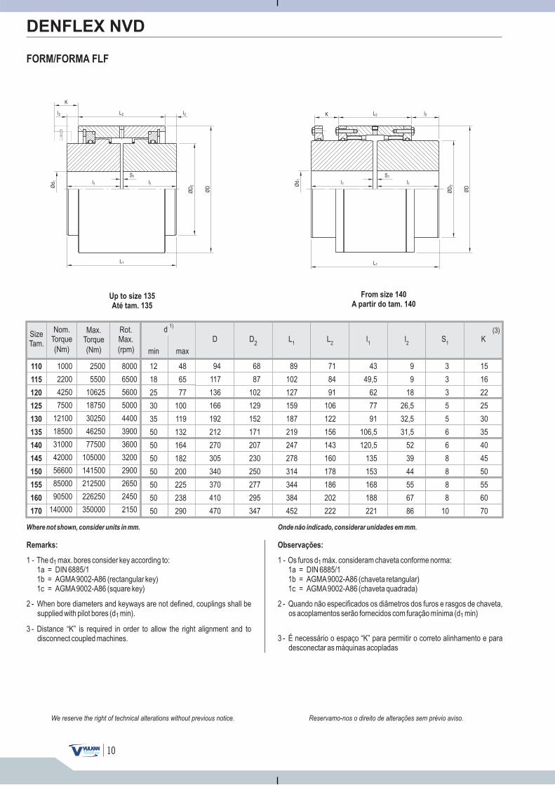
SizeTam.
min max
d 1)
(Nm)
Max.Torque
(Nm)
Nom.Torque
(rpm)
Rot.Max.
48
65
77
100
119
132
164
182
200
225
238
290
12
18
25
30
35
50
50
50
50
50
50
50
110
115
120
125
130
135
140
145
150
155
160
170
1000
2200
4250
7500
12100
18500
31000
42000
56600
85000
90500
140000
2500
5500
10625
18750
30250
46250
77500
105000
141500
212500
226250
350000
8000
6500
5600
5000
4400
3900
3600
3200
2900
2650
2450
2150
10
FORM/FORMA FLF
DENFLEX NVD
D D2
L2
L1
l1
l2
S1
K
Where not shown, consider units in mm. Onde não indicado, considerar unidades em mm.
Remarks: Observações:
(3)
94
117
136
166
192
212
270
305
340
370
410
470
68
87
102
129
152
171
207
230
250
277
295
347
89
102
127
159
187
219
247
278
314
344
384
452
71
84
91
106
122
156
143
160
178
186
202
222
43
49,5
62
77
91
106,5
120,5
135
153
168
188
221
9
9
18
26,5
32,5
31,5
52
39
44
55
67
86
3
3
3
5
5
6
6
8
8
8
8
10
15
16
22
25
30
35
40
45
50
55
60
70
1 - The d max. bores according to:1a = DIN 6885/11b = AGMA9002-A86 (rectangular key)1c = AGMA9002-A86 (square key)
1 consider key
2 - When diameters and keyways are not defined, couplings shall besupplied with pilot bores (d min).1
bore
3 - Distance “K” is required in order to allow the right alignment and todisconnect coupled machines.
1 - Os furos d máx. consideram chaveta conforme norma:1a = DIN 6885/11b = AGMA9002-A86 (chaveta retangular)1c = AGMA9002-A86 (chaveta quadrada)
1
2 - Quando não especificados os diâmetros dos furos e rasgos de chaveta,os acoplamentos serão fornecidos com furação mínima (d min)1
3 - É necessário o espaço “K” para permitir o correto alinhamento e paradesconectar as máquinas acopladas
Up to size 135
Até tam. 135
From size 140
A partir do tam. 140
ØD
ØD
2
L1
Ød 1
S1
l1l1
K l2L2
K
L2 l2
S1
l1 l1Ø
D2Ød 1
L1
ØD
l2
Reservamo-nos o direito de alterações sem prévio aviso.We reserve the right of technical alterations without previous notice.
11
K
ØD
2
Ød 1 l1
Sl1
L1
ØLK
RN
(nºd
e)
furo
s
(hol
es)
ØD
1
ØD
Ød 1
K
l5
l1S
l1
L1
ØD
2
ØLK
RN
(nºd
e)
furo
s
(hol
es)
ØD
1
ØD
K(3)
Sl5
D D2
D1
l1
l2
l3
L1
LKR
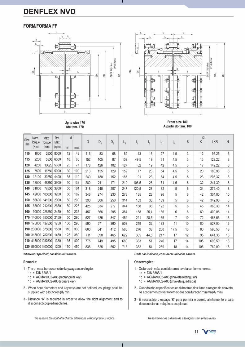
FORM/FORMA FF
DENFLEX NVD
Where not specified, consider units in mm. Onde não indicado, considerar unidades em mm.
Remarks: Observações:
1 - The d max. bores according to:1a = DIN 6885/11b = AGMA9002-A86 (rectangular key)1c = AGMA9002-A86 (square key)
1 consider keyways
2 - When bore diameters and keyways are not defined, couplings shall besupplied with pilot bores (d min).1
3 - Distance “K” is required in order to allow the right alignment and todisconnect coupled machines.
1 - Os furos d máx. consideram chaveta conforme norma:1a = DIN 6885/11b = AGMA9002-A86 (chaveta retangular)1c = AGMA9002-A86 (chaveta quadrada)
1
2 - Quando não especificados os diâmetros dos furos e rasgos de chaveta,os acoplamentos serão fornecidos com furação mínima (d min)1
3 - É necessário o espaço “K” para permitir o correto alinhamento e paradesconectar as máquinas acopladas
N
Up to size 170
Até tam. 170
From size 180
A partir do tam. 180
12
13
17
20
23
32
34
42
42
45
60
72
80
80
95
105
105
95,25
122,22
149,22
180,98
206,37
241,30
279,40
304,80
342,90
368,30
400,05
463,55
527,00
590,50
641,35
698,50
762,00
6
8
6
6
8
8
8
10
8
14
14
16
16
18
18
18
18
4,5
4,5
4,5
4,5
4,5
4,5
5
5
5
5
6
7
11
17,5
17
17
18
3
3
3
5
5
6
6
8
8
8
8
10
10
13
12
14
14
116
152
178
213
240
280
318
346
390
425
457
527
590
660
711
775
838
83
105
126
155
180
211
245
274
306
334
366
425
571
641
698
749
825
68
87
102
129
152
171
207
230
250
277
295
347
360
412
465
495
552
89
102
127
159
187
219
247
278
314
344
384
452
508
565
622
680
718
43
49,5
62
77
91
106,5
120,5
135
153
168
188
221
249
276
305
333
352
16
19
19
23
23
28
28
28
38
38
25,4
28,5
32
38
44,5
51
54
27
31
42
54
64
71
82
96
109
122
136
165
183
200
217
246
259
l3
l2 l2 l5
l3 l3
l2 l2
Reservamo-nos o direito de alterações sem prévio aviso.We reserve the right of technical alterations without previous notice.
110
115
120
125
130
135
140
145
150
155
160
170
180
190
200
210
220
12
18
25
30
35
50
50
50
50
50
50
50
100
110
125
135
150
1000
2200
4250
7500
12100
18500
31000
42000
56600
85000
90500
140000
175000
230000
315000
415000
560000
8000
6500
5600
5000
4400
3900
3600
3200
2900
2650
2450
2150
1750
1550
1450
1330
1200
2500
5500
10625
18750
30250
46250
77500
105000
141500
212500
226250
350000
437500
575000
787500
1037500
1400000
48
65
77
100
119
132
164
182
200
225
238
290
290
330
380
400
450

12
K
ØD
2
Ød 1 l1
Sl1
L1
ØLK
RN
(nºd
e)
furo
s
(hol
es)
ØD
1
ØD
K1
Ød 1
K
l5
l1S
l1
L1
ØD
2
ØLK
RN
(nºd
e)
furo
s
(hol
es)
ØD
1
ØD
K1
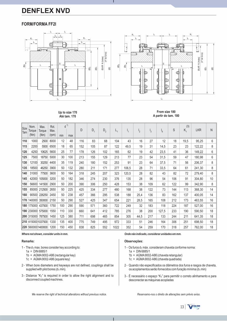
FORM/FORMA FF1I
DENFLEX NVD
Onde não indicado, considerar unidades em mm.
Observações:
1 - Os furos d máx. consideram chaveta conforme norma:1a = DIN 6885/11b = AGMA9002-A86 (chaveta retangular)1c = AGMA9002-A86 (chaveta quadrada)
1
Up to size 170
Até tam. 170
From size 180
A partir do tam. 180
2 - Quando não especificados os diâmetros dos furos e rasgos de chaveta,os acoplamentos serão fornecidos com furação mínima (d min)1
3 - São necessários os espaços “K” e “K ” para permitir o corretoalinhamento e para desconectar as máquinas acopladas
1
l3
l2 l2l6 l5
l3 l3
l2 l2 l6
Reservamo-nos o direito de alterações sem prévio aviso.We reserve the right of technical alterations without previous notice.
Where not shown, consider units in mm.
Remarks:
1 - The d max. bores according to:1a = DIN 6885/11b = AGMA9002-A86 (rectangular key)1c = AGMA9002-A86 (square key)
1 consider key
2 - When bore diameters and keyways are not defined, couplings shall besupplied with pilot bores (d min).1
3 - Distances “K” and “K ” are required in order to allow the right alignmentand to disconnect coupled machines.
1
110
115
120
125
130
135
140
145
150
155
160
170
180
190
200
210
220
12
18
25
30
35
50
50
50
50
50
50
50
100
110
125
135
150
1000
2200
4250
7500
12100
18500
31000
42000
56600
85000
90500
140000
175000
230000
315000
415000
560000
8000
6500
5600
5000
4400
3900
3600
3200
2900
2650
2450
2150
1750
1550
1450
1330
1200
2500
5500
10625
18750
30250
46250
77500
105000
141500
212500
226250
350000
437500
575000
787500
1037500
1400000
48
65
77
100
119
132
164
182
200
225
238
290
290
330
380
400
450
116
152
178
213
240
280
318
346
390
425
457
527
590
660
711
775
838
83
105
126
155
180
211
245
274
306
334
366
425
571
641
698
749
825
68
87
102
129
152
171
207
230
250
277
295
347
360
412
465
495
552
96,5
112
146
186
220
248
285
327
371
412
461
553
615
675
738
826
870
43
49,5
62
77
91
106,5
120,5
135
153
168
188
221
249
276
305
333
352
16
19
19
23
23
28
28
28
38
38
25,4
28,5
32
38
44,5
51
54
27
31
42
54
64
71
82
96
109
122
136
165
183
200
217
246
259
12
14,5
23,5
31,5
37,5
33,5
43
54
62
73
83
108
118
127,5
133
164
170
4,5
4,5
4,5
4,5
4,5
4,5
5
5
5
5
6
7
11
17,5
17
18
18
10,5
13
22
32
38
35
44
57
65
76
85
111
117
123
128
160
166
12
13
17
20
23
32
34
42
42
45
60
72
80
80
95
105
105
19,5
23
36
47
56
61
72
91
99
113
137
173
187
190
211
251
257
95,25
122,22
149,22
180,98
206,37
241,30
279,40
304,80
342,90
368,30
400,05
463,55
527,00
590,50
641,35
698,50
762,00
6
8
6
6
8
8
8
10
8
14
14
16
16
18
18
18
18
D D2D
1L
1l1
l2
l3
l5
l6
S K K1
LKR N(3) (3)
110
115
120
125
130
135
140
145
150
155
160
170
180
190
200
210
220
12
18
25
30
35
50
50
50
50
50
50
50
100
110
125
135
150
1000
2200
4250
7500
12100
18500
31000
42000
56600
85000
90500
140000
175000
230000
315000
415000
560000
8000
6500
5600
5000
4400
3900
3600
3200
2900
2650
2450
2150
1750
1550
1450
1330
1200
2500
5500
10625
18750
30250
46250
77500
105000
141500
212500
226250
350000
437500
575000
787500
1037500
1400000
48
65
77
100
119
132
164
182
200
225
238
290
290
330
380
400
450
13
FORM/FORMA FF2I
DENFLEX NVD
Onde não indicado, considerar unidades em mm.
Observações:
1 - Os furos d máx. consideram chaveta conforme norma:1a = DIN 6885/11b = AGMA9002-A86 (chaveta retangular)1c = AGMA9002-A86 (chaveta quadrada)
1
2 - Quando não especificados os diâmetros dos furos e rasgos de chaveta,os acoplamentos serão fornecidos com furação mínima (d min)1
3 - É necessário o espaço “K ” para permitir o correto alinhamento e paradesconectar as máquinas acopladas
1
Up to size 170
Até tam. 170
From size 180
A partir do tam. 180
K1
ØD
2
Ød 1 l1
Sl1
L1
ØLK
RN
(nºd
e)
furo
s
(hol
es)
ØD
1
ØD
K1
Ød 1
K1
l1S
l1
L1
ØD
2
ØLK
RN
(nºd
e)
furo
s
(hol
es)
ØD
1
ØD
K1
l3l3
l2l2
l6 l6
l3 l3
l6 l6
Reservamo-nos o direito de alterações sem prévio aviso.We reserve the right of technical alterations without previous notice.
Where not shown, consider units in mm.
Remarks:
1 - The d max. bores according to:1a = DIN 6885/11b = AGMA9002-A86 (rectangular key)1c = AGMA9002-A86 (square key)
1 consider key
2 - When bore diameters and keyways are not defined, couplings shall besupplied with pilot bores (d min).1
3 - Distance “K ” is required in order to allow the right alignment and todisconnect coupled machines.
1
19,5
23
36
47
56
61
72
91
99
113
137
173
187
190
211
251
257
95,25
122,22
149,22
180,98
206,37
241,30
279,40
304,80
342,90
368,30
400,05
463,55
527,00
590,50
641,35
698,50
762,00
6
8
6
6
8
8
8
10
8
14
14
16
16
18
18
18
18
12
14,5
23,5
31,5
37,5
33,5
43
54
62
73
83
108
118
127,5
133
164
170
18
23
41
59
71
64
82
106
122
144
162
212
224
233
244
306
318
116
152
178
213
240
280
318
346
390
425
457
527
590
660
711
775
838
83
105
126
155
180
211
245
274
306
334
366
425
571
641
698
749
825
68
87
102
129
152
171
207
230
250
277
295
347
360
412
465
495
552
104
122
165
213
253
277
323
376
428
480
538
654
722
785
854
972
1022
43
49,5
62
77
91
106,5
120,5
135
153
168
188
221
249
276
305
333
352
16
19
19
23
23
28
28
28
38
38
25,4
28,5
32
38
44,5
51
54
27
31
42
54
64
71
82
96
109
122
136
165
183
200
217
246
259
K1LKR N
(3)l6
SD D2
D1
L1
l1
l2
l3

110
115
120
125
130
135
140
145
150
155
160
170
180
190
200
210
220
12
18
25
30
35
50
50
50
50
50
50
50
100
110
125
135
150
1000
2200
4250
7500
12100
18500
31000
42000
56600
85000
90500
140000
175000
230000
315000
415000
560000
8000
6500
5600
5000
4400
3900
3600
3200
2900
2650
2450
2150
1750
1550
1450
1330
1200
2500
5500
10625
18750
30250
46250
77500
105000
141500
212500
226250
350000
437500
575000
787500
1037500
1400000
48
65
77
100
119
132
164
182
200
225
238
290
290
330
380
400
450
14
FORM/FORMA FF1L
DENFLEX NVD
Onde não indicado, considerar unidades em mm.
Observações:
Up to size 170
Até tam. 170
From size 180
A partir do tam. 180
1 - Os furos d máx. consideram chaveta conforme norma:1a = DIN 6885/11b = AGMA9002-A86 (chaveta retangular)1c = AGMA9002-A86 (chaveta quadrada)
1
2 - Quando não especificados os diâmetros dos furos e rasgos de chaveta,os acoplamentos serão fornecidos com furação mínima (d min)1
3 - São necessários os espaços “K” e “K ” para permitir o corretoalinhamento e para desconectar as máquinas acopladas
1
Ød 1
K1
lS
l1
L1
ØD
2
ØLK
RN
(nºd
e)
furo
s
(hol
es)
ØD
1
ØD
K K1
ØD
2
Ød 1 l
Sl1
L1
ØLK
RN
(nºd
e)
furo
s
(hol
es)
ØD
1
ØD
K
l5
l3 l3
l2 l2
l7
l5
l3 l3
l7
Reservamo-nos o direito de alterações sem prévio aviso.We reserve the right of technical alterations without previous notice.
Where not shown, consider units in mm.
Remarks:
1 - The d max. bores according to:1a = DIN 6885/11b = AGMA9002-A86 (rectangular key)1c = AGMA9002-A86 (square key)
1 consider key
2 - When bore diameters and keyways are not defined, couplings shall besupplied with pilot bores (d min).1
3 - Distances “K” and “K ” are required in order to allow the right alignmentand to disconnect coupled machines.
1
12
13
17
20
23
32
34
42
42
45
60
72
80
80
95
105
105
19,5
23
36
47
56
61
72
91
99
113
137
173
187
190
211
251
257
116
152
178
213
240
280
318
346
390
425
457
527
590
660
711
775
838
83
105
126
155
180
211
245
274
306
334
366
425
571
641
698
749
825
68
87
102
129
152
171
207
230
250
277
295
347
360
412
465
508,5
552
155,5
176,5
214
258
294
325,5
367,5
436
513
542
578
642
839
923
1012
1125
1186
102
114
130
149
165
184
203
244
295
298
305
310
473
524
579
632
668
43
49,5
62
77
91
106,5
120,5
135
153
168
188
221
249
276
305
333
352
16
19
19
23
23
28
28
28
38
38
25,4
28,5
32
38
44,5
51
54
27
31
42
54
64
71
82
96
109
122
136
165
183
200
217
246
259
71
79
92
104
112
111
126
163
204
203
200
197
342
375
407
463
486
4,5
4,5
4,5
4,5
4,5
4,5
5
5
5
5
6
7
11
17,5
17
18
18
10,5
13
22
32
38
35
44
57
65
76
85
111
117
123
128
160
166
95,25
122,22
149,22
180,98
206,37
241,30
279,40
304,80
342,90
368,30
400,05
463,55
527,00
590,50
641,35
698,50
762,00
6
8
6
6
8
8
8
10
8
14
14
16
16
18
18
18
18
K K1
(3) (3)D D
2D
1L
1l l
1l2
l3
l5
l7
S LKR N

110
115
120
125
130
135
140
145
150
155
160
170
180
190
200
210
220
12
18
25
30
35
50
50
50
50
50
50
50
100
110
125
135
150
1000
2200
4250
7500
12100
18500
31000
42000
56600
85000
90500
140000
175000
230000
315000
415000
560000
8000
6500
5600
5000
4400
3900
3600
3200
2900
2650
2450
2150
1750
1550
1450
1330
1200
2500
5500
10625
18750
30250
46250
77500
105000
141500
212500
226250
350000
437500
575000
787500
1037500
1400000
48
65
77
100
119
132
164
182
200
225
238
290
290
330
380
400
450
15
Onde não indicado, considerar unidades em mm.
Observações:
1 - Os furos d e d máx. consideram chaveta conforme norma:1a = DIN 6885/11b = AGMA9002-A86 (chaveta retangular)1c = AGMA9002-A86 (chaveta quadrada)
1
2 - Quando não especificados os diâmetros dos furos e rasgos de chaveta,os acoplamentos serão fornecidos com furação mínima (dd min)1
3 - É necessário o espaço “K ” para permitir o correto alinhamento e paradesconectar as máquinas acopladas
1
FORM/FORMA FF1IL
DENFLEX NVD
Up to size 170
Até tam. 170
From size 180
A partir do tam. 180
Ød 1
K1
lS
l1
L1
ØD
2
ØLK
RN
(nºd
e)
furo
s
(hol
es)
ØD
1
ØD
K1 K1
ØD
2
Ød 1 l
Sl1
L1
ØLK
RN
(nºd
e)
furo
s
(hol
es)
ØD
1
ØD
K1l3
l2 l2l6
l7
l3l3 l3
l6
l7
Reservamo-nos o direito de alterações sem prévio aviso.We reserve the right of technical alterations without previous notice.
Where not shown, consider units in mm.
Remarks:
1 - The d and d max. bores according to:1a = DIN 6885/11b = AGMA9002-A86 (rectangular key)1c = AGMA9002-A86 (square key)
1 consider key
2 - When bore diameters and keyways are not defined, couplings shall besupplied with pilot bores (dd min).1
3 - Distance “K ” is required in order to allow the right alignment and todisconnect coupled machines.
1
95,25
122,22
149,22
180,98
206,37
241,30
279,40
304,80
342,90
368,30
400,05
463,55
527,00
590,50
641,35
698,50
762,00
6
8
6
6
8
8
8
10
8
14
14
16
16
18
18
18
18
12
14,5
23,5
31,5
37,5
33,5
43
54
62
73
83
108
118
127,5
133
164
170
71
79
92
104
112
111
126
163
204
203
200
197
342
375
407
463
486
19,5
23
36
47
56
61
72
91
99
113
137
173
187
190
211
251
257
18
23
41
59
71
64
82
106
122
144
162
212
224
233
244
306
318
116
152
178
213
240
280
318
346
390
425
457
527
590
660
711
775
838
83
105
126
155
180
211
245
274
306
334
366
425
571
641
698
749
825
68
87
102
129
152
171
207
230
250
277
295
347
360
412
465
495
552
163
187
233
285
327
355
406
485
570
610
655
743
946
1033
1128
1271
1338
43
49,5
62
77
91
106,5
120,5
135
153
168
188
221
249
276
305
333
352
102
114
130
149
165
184
203
244
295
298
305
310
473
524
579
632
668
16
19
19
23
23
28
28
28
38
38
25,4
28,5
32
38
44,5
51
54
27
31
42
54
64
71
82
96
109
122
136
165
183
200
217
246
259
LKR Nl6 l7
K1
(3)SD D
2D
1L
1l1
l l2
l3
110
115
120
125
130
135
140
145
150
155
160
170
180
190
200
210
220
12
18
25
30
35
50
50
50
50
50
50
50
100
110
125
135
150
1000
2200
4250
7500
12100
18500
31000
42000
56600
85000
90500
140000
175000
230000
315000
415000
560000
8000
6500
5600
5000
4400
3900
3600
3200
2900
2650
2450
2150
1750
1550
1450
1330
1200
2500
5500
10625
18750
30250
46250
77500
105000
141500
212500
226250
350000
437500
575000
787500
1037500
1400000
48
65
77
100
119
132
164
182
200
225
238
290
290
330
380
400
450
16
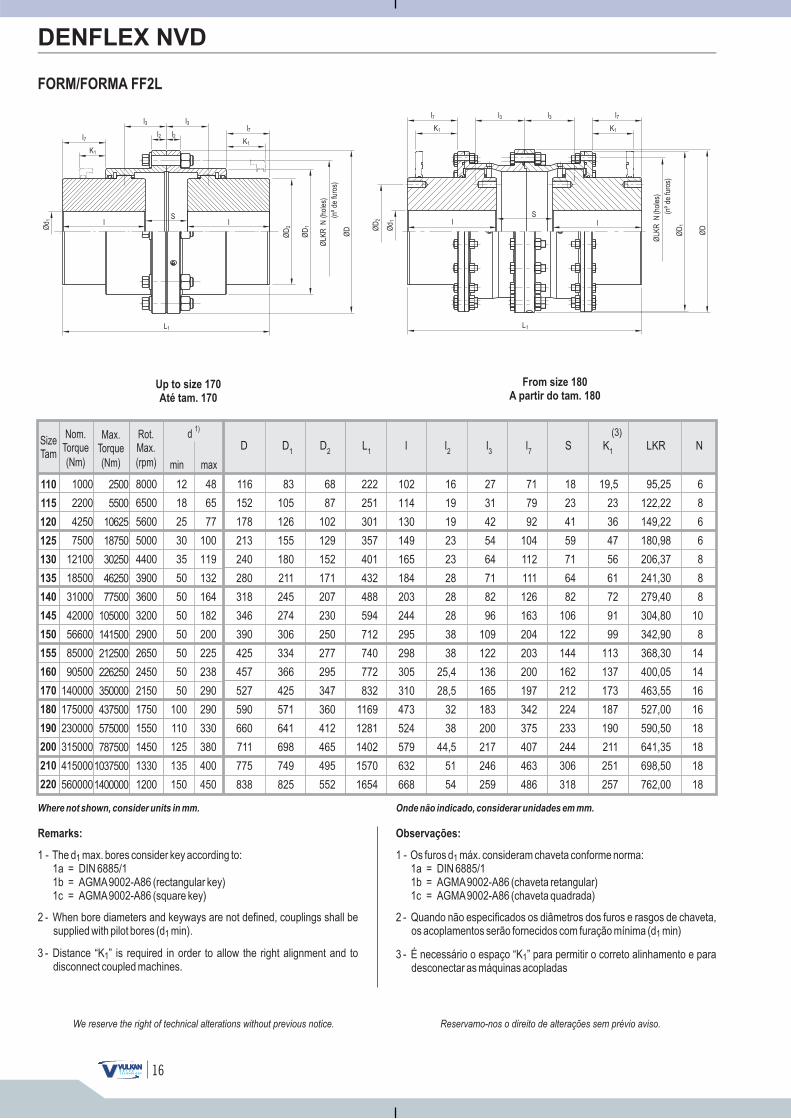
FORM/FORMA FF2L
DENFLEX NVD
Onde não indicado, considerar unidades em mm.
Observações:
1 - Os furos d máx. consideram chaveta conforme norma:1a = DIN 6885/11b = AGMA9002-A86 (chaveta retangular)1c = AGMA9002-A86 (chaveta quadrada)
1
2 - Quando não especificados os diâmetros dos furos e rasgos de chaveta,os acoplamentos serão fornecidos com furação mínima (d min)1
3 - É necessário o espaço “K ” para permitir o correto alinhamento e paradesconectar as máquinas acopladas
1
Up to size 170
Até tam. 170
From size 180
A partir do tam. 180
K1
ØD
2
Ød 1 l
Sl
L1
ØLK
RN
(nºd
e)
furo
s
(hol
es)
ØD
1
ØD
K1
Ød 1
K1
lS
L1
ØD
2
ØLK
RN
(nºd
e)
furo
s
(hol
es)
ØD
1
ØD
K1
l
l3 l3
l2 l2l7
l3 l3l7 l7
l7
Reservamo-nos o direito de alterações sem prévio aviso.We reserve the right of technical alterations without previous notice.
Where not shown, consider units in mm.
Remarks:
1 - The d max. bores according to:1a = DIN 6885/11b = AGMA9002-A86 (rectangular key)1c = AGMA9002-A86 (square key)
1 consider key
2 - When bore diameters and keyways are not defined, couplings shall besupplied with pilot bores (d min).1
3 - Distance “K ” is required in order to allow the right alignment and todisconnect coupled machines.
1
K1
LKR N(3)
l7
SD D2
D1
L1
l l2
l3
19,5
23
36
47
56
61
72
91
99
113
137
173
187
190
211
251
257
95,25
122,22
149,22
180,98
206,37
241,30
279,40
304,80
342,90
368,30
400,05
463,55
527,00
590,50
641,35
698,50
762,00
6
8
6
6
8
8
8
10
8
14
14
16
16
18
18
18
18
18
23
41
59
71
64
82
106
122
144
162
212
224
233
244
306
318
116
152
178
213
240
280
318
346
390
425
457
527
590
660
711
775
838
83
105
126
155
180
211
245
274
306
334
366
425
571
641
698
749
825
68
87
102
129
152
171
207
230
250
277
295
347
360
412
465
495
552
222
251
301
357
401
432
488
594
712
740
772
832
1169
1281
1402
1570
1654
16
19
19
23
23
28
28
28
38
38
25,4
28,5
32
38
44,5
51
54
27
31
42
54
64
71
82
96
109
122
136
165
183
200
217
246
259
71
79
92
104
112
111
126
163
204
203
200
197
342
375
407
463
486
102
114
130
149
165
184
203
244
295
298
305
310
473
524
579
632
668
SizeTam.
min max
d 1)
(Nm)
Max.Torque
(Nm)
Nom.Torque
(rpm)
Rot.Max.
48
65
77
100
119
132
164
182
200
225
238
290
12
18
25
30
35
50
50
50
50
50
50
50
110
115
120
125
130
135
140
145
150
155
160
170
1000
2200
4250
7500
12100
18500
31000
42000
56600
85000
90500
140000
2500
5500
10625
18750
30250
46250
77500
105000
141500
212500
226250
350000
8000
6500
5600
5000
4400
3900
3600
3200
2900
2650
2450
2150
17
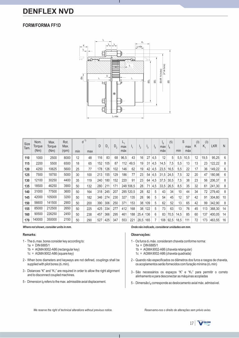
FORM/FORMA FF1D
DENFLEX NVD
Onde não indicado, considerar unidades em mm.
Observações:
1 - Os furos d máx. consideram chaveta conforme norma:1a = DIN 6885/11b = AGMA9002-A86 (chaveta retangular)1c = AGMA9002-A86 (chaveta quadrada)
1
2 - Quando não especificados os diâmetros dos furos e rasgos de chaveta,os acoplamentos serão fornecidos com furação mínima (d min)1
3 - São necessários os espaços “K” e “K ” para permitir o corretoalinhamento e para desconectar as máquinas acopladas
1
5 - Dimensão l corresponde ao deslocamento axial máx. admissível.8
Ød 1
K
l1S
L máx1
ØD
2
ØLK
RN
(nºd
efu
ros)
(hol
es)
ØD
1
ØD
K1
l1
l5
l3
l2 l2l6 máx
l8
Reservamo-nos o direito de alterações sem prévio aviso.We reserve the right of technical alterations without previous notice.
Where not shown, consider units in mm.
Remarks:
1 - The d max. bores according to:1a = DIN 6885/11b = AGMA9002-A86 (rectangular key)1c = AGMA9002-A86 (square key)
1 consider key
2 - When bore diameters and keyways are not defined, couplings shall besupplied with pilot bores (d min).1
3 - Distances “K” and “K ” are required in order to allow the right alignmentand to disconnect coupled machines.
1
5 - Dimension l refers to the max. admissible axial .8 displacement
K K1
(3) (3)D D
2D
1
L1
l1
l2
l3
l5
l8
l6
SLKR N
minmaxmáx
maxmáx
maxmáx
(5)
12
13
17
20
23
32
34
42
42
45
60
72
19,5
23
36
47
56
61
72
91
99
113
137
173
116
152
178
213
240
280
318
346
390
425
457
527
83
105
126
155
180
211
245
274
306
334
366
425
68
87
102
129
152
171
207
230
250
277
295
347
96,5
112
146
186
220
248
285
327
371
412
461
553
43
49,5
62
77
91
106,5
120,5
135
153
168
188
221
16
19
19
23
23
28
28
28
38
38
25,4
28,5
27
31
42
54
64
71
82
96
109
122
136
165
5
7,5
16,5
24,5
30,5
26,5
34
45
52
63
70,5
92,5
4,5
4,5
4,5
4,5
4,5
4,5
5
5
5
5
6
7
5,5
5,5
5,5
7,5
7,5
8,5
10
12
13
13
14,5
18,5
10,5
13
22
32
38
35
44
57
65
76
85
111
95,25
122,22
149,22
180,98
206,37
241,30
279,40
304,80
342,90
368,30
400,05
463,55
6
8
6
6
8
8
8
10
8
14
14
16
12
14,5
23,5
31,5
37,5
33,5
43
54
62
73
83
108
SizeTam.
min max
d 1)
(Nm)
Max.Torque
(Nm)
Nom.Torque
(rpm)
Rot.Max.
48
65
77
100
119
132
164
182
200
225
238
290
12
18
25
30
35
50
50
50
50
50
50
50
110
115
120
125
130
135
140
145
150
155
160
170
1000
2200
4250
7500
12100
18500
31000
42000
56600
85000
90500
140000
2500
5500
10625
18750
30250
46250
77500
105000
141500
212500
226250
350000
8000
6500
5600
5000
4400
3900
3600
3200
2900
2650
2450
2150
18
FORM/FORMA FF1ID
DENFLEX NVD
Onde não indicado, considerar unidades em mm.
Observações:
1 - Os furos d máx. consideram chaveta conforme norma:1a = DIN 6885/11b = AGMA9002-A86 (chaveta retangular)1c = AGMA9002-A86 (chaveta quadrada)
1
2 - Quando não especificados os diâmetros dos furos e rasgos de chaveta,os acoplamentos serão fornecidos com furação mínima (d min)1
3 - É necessário o espaço “K ” para permitir o correto alinhamento e paradesconectar as máquinas acopladas
1
5 - Dimensão l corresponde ao deslocamento axial máx. admissível.8
Ød 1
K1
l1 S
L máx1
ØD
2
ØLK
RN
(nºd
efu
ros)
(hol
es)
ØD
1
ØD
K1
l1
l3
l2 l2
l6
l6
l8
Reservamo-nos o direito de alterações sem prévio aviso.We reserve the right of technical alterations without previous notice.
Where not shown, consider units in mm.
Remarks:
1 - The d max. bores :1a = DIN 6885/11b = AGMA9002-A86 (rectangular key)1c = AGMA9002-A86 (square key)
1 consider key according to
2 - When bore diameters and keyways are not defined, couplings shall besupplied with pilot bores (d min).1
3 - Distance “K ” is required in order to allow the right alignment and todisconnect coupled machines.
1
5 - Dimension l refers to the max. admissible axial .8 displacement
Smaxmáxmin
K1
(3)D D
2D
1
L1
l1
l2
l3
l8
l6
LKR Nmaxmáx
(5)
19,5
23
36
47
56
61
72
91
99
113
137
173
116
152
178
213
240
280
318
346
390
425
457
527
83
105
126
155
180
211
245
274
306
334
366
425
68
87
102
129
152
171
207
230
250
277
295
347
104
122
165
213
253
277
323
376
428
480
538
654
43
49,5
62
77
91
106,5
120,5
135
153
168
188
221
16
19
19
23
23
28
28
28
38
38
25,4
28,5
27
31
42
54
64
71
82
96
109
122
136
165
7,5
10
19
27
33
29
38
49
57
68
77
101
95,25
122,22
149,22
180,98
206,37
241,30
279,40
304,80
342,90
368,30
400,05
463,55
6
8
6
6
8
8
8
10
8
14
14
16
12
14,5
23,5
31,5
37,5
33,5
43
54
62
73
83
108
10,5
13
22
32
38
35
44
57
65
76
85
111
18
23
41
59
71
64
82
106
122
144
162
212
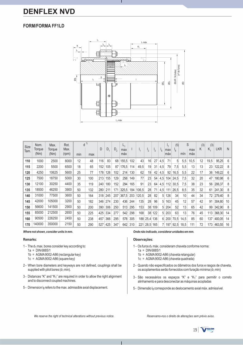
SizeTam.
min max
d 1)
(Nm)
Max.Torque
(Nm)
Nom.Torque
(rpm)
Rot.Max.
48
65
77
100
119
132
164
182
200
225
238
290
12
18
25
30
35
50
50
50
50
50
50
50
110
115
120
125
130
135
140
145
150
155
160
170
1000
2200
4250
7500
12100
18500
31000
42000
56600
85000
90500
140000
2500
5500
10625
18750
30250
46250
77500
105000
141500
212500
226250
350000
8000
6500
5600
5000
4400
3900
3600
3200
2900
2650
2450
2150
19
FORM/FORMA FF1LD
DENFLEX NVD
Onde não indicado, considerar unidades em mm.
Observações:
1 - Os furos d máx. consideram chaveta conforme norma:1a = DIN 6885/11b = AGMA9002-A86 (chaveta retangular)1c = AGMA9002-A86 (chaveta quadrada)
1
2 - Quando não especificados os diâmetros dos furos e rasgos de chaveta,os acoplamentos serão fornecidos com furação mínima (d min)1
3 - São necessários os espaços “K” e “K ” para permitir o corretoalinhamento e para desconectar as máquinas acopladas
1
5 - Dimensão l corresponde ao deslocamento axial máx. admissível.8
Ød 1
K
l1S
L máx1
ØD
2
ØLK
RN
(nºd
efu
ros)
(hol
es)
ØD
1
ØD
K1
l
l5
l3
l2l7 máx
l2
l8
Reservamo-nos o direito de alterações sem prévio aviso.We reserve the right of technical alterations without previous notice.
Where not shown, consider units in mm.
Remarks:
1 - The d max. bores :1a = DIN 6885/11b = AGMA9002-A86 (rectangular key)1c = AGMA9002-A86 (square key)
1 consider key according to
2 - When bore diameters and keyways are not defined, couplings shall besupplied with pilot bores (d min).1
3 - Distances “K” and “K ” are required in order to allow the right alignmentand to disconnect coupled machines.
1
5 - Dimension l refers to the max. admissible axial .8 displacement
l2
l3
K K1
(3) (3)D D
2D
1
L1
l1
l l5
l8
l7
SLKR N
mínmaxmáx
maxmáx
maxmáx
(5)
16
19
19
23
23
28
28
28
38
38
25,4
28,5
27
31
42
54
64
71
82
96
109
122
136
165
12
13
17
20
23
32
34
42
42
45
60
72
19,5
23
36
47
56
61
72
91
99
113
137
173
116
152
178
213
240
280
318
346
390
425
457
527
83
105
126
155
180
211
245
274
306
334
366
425
68
87
102
129
152
171
207
230
250
277
295
347
155,5
176,5
214
258
294
325,5
367,5
436
513
542
578
642
43
49,5
62
77
91
106,5
120,5
135
153
168
188
221
102
114
130
149
165
184
203
244
295
298
305
310
5
7,5
16,5
24,5
30,5
26,5
34
45
52
63
70,5
92,5
4,5
4,5
4,5
4,5
4,5
4,5
5
5
5
5
6
7
5,5
5,5
5,5
7,5
7,5
8,5
10
12
13
13
14,5
18,5
10,5
13
22
32
38
35
44
57
65
76
85
111
95,25
122,22
149,22
180,98
206,37
241,30
279,40
304,80
342,90
368,30
400,05
463,55
6
8
6
6
8
8
8
10
8
14
14
16
71
79
92
104
112
111
126
163
204
203
200
197

SizeTam.
min max
d 1)
(Nm)
Max.Torque
(Nm)
Nom.Torque
(rpm)
Rot.Max.
48
65
77
100
119
132
164
182
200
225
238
290
12
18
25
30
35
50
50
50
50
50
50
50
110
115
120
125
130
135
140
145
150
155
160
170
1000
2200
4250
7500
12100
18500
31000
42000
56600
85000
90500
140000
2500
5500
10625
18750
30250
46250
77500
105000
141500
212500
226250
350000
8000
6500
5600
5000
4400
3900
3600
3200
2900
2650
2450
2150
20
FORM/FORMA FFI1LD
DENFLEX NVD
Onde não indicado, considerar unidades em mm.
Observações:
1 - Os furos d máx. consideram chaveta conforme norma:1a = DIN 6885/11b = AGMA9002-A86 (chaveta retangular)1c = AGMA9002-A86 (chaveta quadrada)
1
2 - Quando não especificados os diâmetros dos furos e rasgos de chaveta,os acoplamentos serão fornecidos com furação mínima (d min)1
3 - É necessário o espaço “K ” para permitir o correto alinhamento e paradesconectar as máquinas acopladas
1
5 - Dimensão l corresponde ao deslocamento axial máx. admissível.8
Ød 1
K1
l1S
L máx1
ØD
2
ØLK
RN
(nºd
e)
furo
s
(hol
es)
ØD
1
ØD
K1
l
l3
l2 l2
l6
l7 máx
l8
Reservamo-nos o direito de alterações sem prévio aviso.We reserve the right of technical alterations without previous notice.
Where not shown, consider units in mm.
Remarks:
1 - The d max. bores :1a = DIN 6885/11b = AGMA9002-A86 (rectangular key)1c = AGMA9002-A86 (square key)
1 consider key according to
2 - When bore diameters and keyways are not defined, couplings shall besupplied with pilot bores (d min).1
3 - Distance “K ” is required in order to allow the right alignment and todisconnect coupled machines.
1
5 - Dimension l refers to the max. admissible axial .8 displacement
l2
l3
l7
l1
L1
Smaxmáxmin
K1
(3)D D
2D
1l l
8LKR N
(5)l6
27
31
42
54
64
71
82
96
109
122
136
165
71
79
92
104
112
111
126
163
204
203
200
197
43
49,5
62
77
91
106,5
120,5
135
153
168
188
221
163
186,5
233
285
327
354,5
405,5
485
570
610
655
743
19,5
23
36
47
56
61
72
91
99
113
137
173
116
152
178
213
240
280
318
346
390
425
457
527
83
105
126
155
180
211
245
274
306
334
366
425
68
87
102
129
152
171
207
230
250
277
295
347
7,5
10
19
27
33
29
38
49
57
68
77
101
95,25
122,22
149,22
180,98
206,37
241,30
279,40
304,80
342,90
368,30
400,05
463,55
6
8
6
6
8
8
8
10
8
14
14
16
10,5
13
22
32
38
35
44
57
65
76
85
111
18
23
41
59
71
64
82
106
122
144
162
212
102
114
130
149
165
184
203
244
295
298
305
310
12
14,5
23,5
31,5
37,5
33,5
43
54
62
73
83
108
16
19
19
23
23
28
28
28
38
38
25,4
28,5

21
Reservamo-nos o direito de alterações sem prévio aviso.We reserve the right of technical alterations without previous notice.
21 1D L LKR N
Donde no está indicado, considere unidades en mm.
(2) (1)d max/máx1
Observaciones:
1 - Los agujeros d máx. consideran chaveta conforme a la norma:1a = DIN 6885/11b = AGMA9002-A86 (chaveta rectangular)1c = AGMA9002-A86 (chaveta cuadrada)
2 - Cuando no son espicificados los diámetros de los agujeros y los rasgos
1
de la chaveta, los acoplamientos serán suministrados con agujeromínimo (d min)
3 - El espacio "K ” es necesario para permitir un correcto alineamiento y
1
para desconectar las máquinas acopladas
5 - La dimensión l corresponde al dislocamiento axial máx. admisible
1
8
lll ll862 31
(5)
Ød 1
K1
lS
1
L1
ØD
2
ØLK
RN
(nºd
efu
ros
)
(hol
es)
ØD
1
ØD
K1
l
l
l l
l
l
l
1
3
2 2
6
6
8
Where not shown, consider units in mm.
Remarks:
1 - The d max. bores :1a = DIN 6885/11b = AGMA9002-A86 (rectangular key)1c = AGMA9002-A86 (square key)
1 consider key according to
2 - When bore diameters and keyways are not defined, couplings shall besupplied with pilot bores (d min).
3 - Distance “K ” is required in order to allow the right alignment and to
1
disconnect coupled machines.
5 - Dimension l refers to the max. admissible axial .
1
8 displacement
l2
l3
l1
L1
D D2
D1
l6
Smaxmáxmin
K1
(3)l8
LKR N(5)
27
31
42
54
64
71
82
96
109
122
136
165
43
49,5
62
77
91
106,5
120,5
135
153
168
188
221
104
122
165
213
253
277
323
376
428
480
538
654
116
152
178
213
240
280
318
346
390
425
457
527
83
105
126
155
180
211
245
274
306
334
366
425
68
87
102
129
152
171
207
230
250
277
295
347
19,5
23
36
47
56
61
72
91
99
113
137
173
5
7,5
16,5
24,5
30,5
26,5
34
45
52
6370,5
92,5
95,25
122,22
149,22
180,98
206,37
241,30
279,40
304,80
342,90
368,30
400,05
463,55
6
8
6
6
8
8
8
10
8
14
14
16
8
5,5
5,5
7,5
7,5
8,5
10
12
13
13
14,5
18,5
18
23
41
59
71
64
82
106
122
144
162
212
12
14,5
23,5
31,5
37,5
33,5
43
54
62
73
83
108
16
19
19
23
23
28
28
28
38
38
25,4
28,5
SizeTam.
min max
d 1)
(Nm)
Max.Torque
(Nm)
Nom.Torque
(rpm)
Rot.Max.
48
65
77
100
119
132
164
182
200
225
238
290
12
18
25
30
35
50
50
50
50
50
50
50
110
115
120
125
130
135
140
145
150
155
160
170
1000
2200
4250
7500
12100
18500
31000
42000
56600
85000
90500
140000
2500
5500
10625
18750
30250
46250
77500
105000
141500
212500
226250
350000
8000
6500
5600
5000
4400
3900
3600
3200
2900
2650
2450
2150
Onde não indicado, considerar unidades em mm.
Observações:
1 - Os furos d máx. consideram chaveta conforme norma:1a = DIN 6885/11b = AGMA9002-A86 (chaveta retangular)1c = AGMA9002-A86 (chaveta quadrada)
1
2 - Quando não especificados os diâmetros dos furos e rasgos de chaveta,os acoplamentos serão fornecidos com furação mínima (d min)1
3 - É necessário o espaço “K ” para permitir o correto alinhamento e paradesconectar as máquinas acopladas
1
5 - Dimensão l corresponde ao deslocamento axial máx. admissível porcubo
8
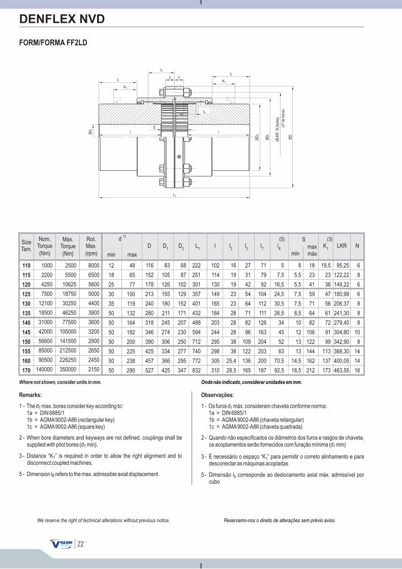
SizeTam.
min max
d 1)
(Nm)
Max.Torque
(Nm)
Nom.Torque
(rpm)
Rot.Max.
48
65
77
100
119
132
164
182
200
225
238
290
12
18
25
30
35
50
50
50
50
50
50
50
110
115
120
125
130
135
140
145
150
155
160
170
1000
2200
4250
7500
12100
18500
31000
42000
56600
85000
90500
140000
2500
5500
10625
18750
30250
46250
77500
105000
141500
212500
226250
350000
8000
6500
5600
5000
4400
3900
3600
3200
2900
2650
2450
2150
22
FORM/FORMA FF2LD
DENFLEX NVD
Onde não indicado, considerar unidades em mm.
Observações:
1 - Os furos d máx. consideram chaveta conforme norma:1a = DIN 6885/11b = AGMA9002-A86 (chaveta retangular)1c = AGMA9002-A86 (chaveta quadrada)
1
2 - Quando não especificados os diâmetros dos furos e rasgos de chaveta,os acoplamentos serão fornecidos com furação mínima (d min)1
3 - É necessário o espaço “K ” para permitir o correto alinhamento e paradesconectar as máquinas acopladas
1
5 - Dimensão l corresponde ao deslocamento axial máx. admissível porcubo
8
Ød 1
K1
lS
L1
ØD
2
ØLK
RN
(nºd
e)
furo
s
(hol
es)
ØD
1
ØD
K1
l
l3
l2l7
l8
l7l2
Reservamo-nos o direito de alterações sem prévio aviso.We reserve the right of technical alterations without previous notice.
Where not shown, consider units in mm.
Remarks:
1 - The d max. bores :1a = DIN 6885/11b = AGMA9002-A86 (rectangular key)1c = AGMA9002-A86 (square key)
1 consider key according to
2 - When bore diameters and keyways are not defined, couplings shall besupplied with pilot bores (d min).1
3 - Distance “K ” is required in order to allow the right alignment and todisconnect coupled machines.
1
5 - Dimension l refers to the max. admissible axial .8 displacement
l7
l8
(5)l2
l3
L1
Smaxmáxmin
K1
(3)D D
2D
1l LKR N
71
79
92
104
112
111
126
163
204
203
200
197
5
7,5
16,5
24,5
30,5
26,5
34
45
52
63
70,5
92,5
16
19
19
23
23
28
28
28
38
38
25,4
28,5
27
31
42
54
64
71
82
96
109
122
136
165
222
251
301
357
401
432
488
594
712
740
772
832
19,5
23
36
47
56
61
72
91
99
113
137
173
116
152
178
213
240
280
318
346
390
425
457
527
83
105
126
155
180
211
245
274
306
334
366
425
68
87
102
129
152
171
207
230
250
277
295
347
95,25
122,22
149,22
180,98
206,37
241,30
279,40
304,80
342,90
368,30
400,05
463,55
6
8
6
6
8
8
8
10
8
14
14
16
8
5,5
5,5
7,5
7,5
8,5
10
12
13
13
14,5
18,5
18
23
41
59
71
64
82
106
122
144
162
212
102
114
130
149
165
184
203
244
295
298
305
310
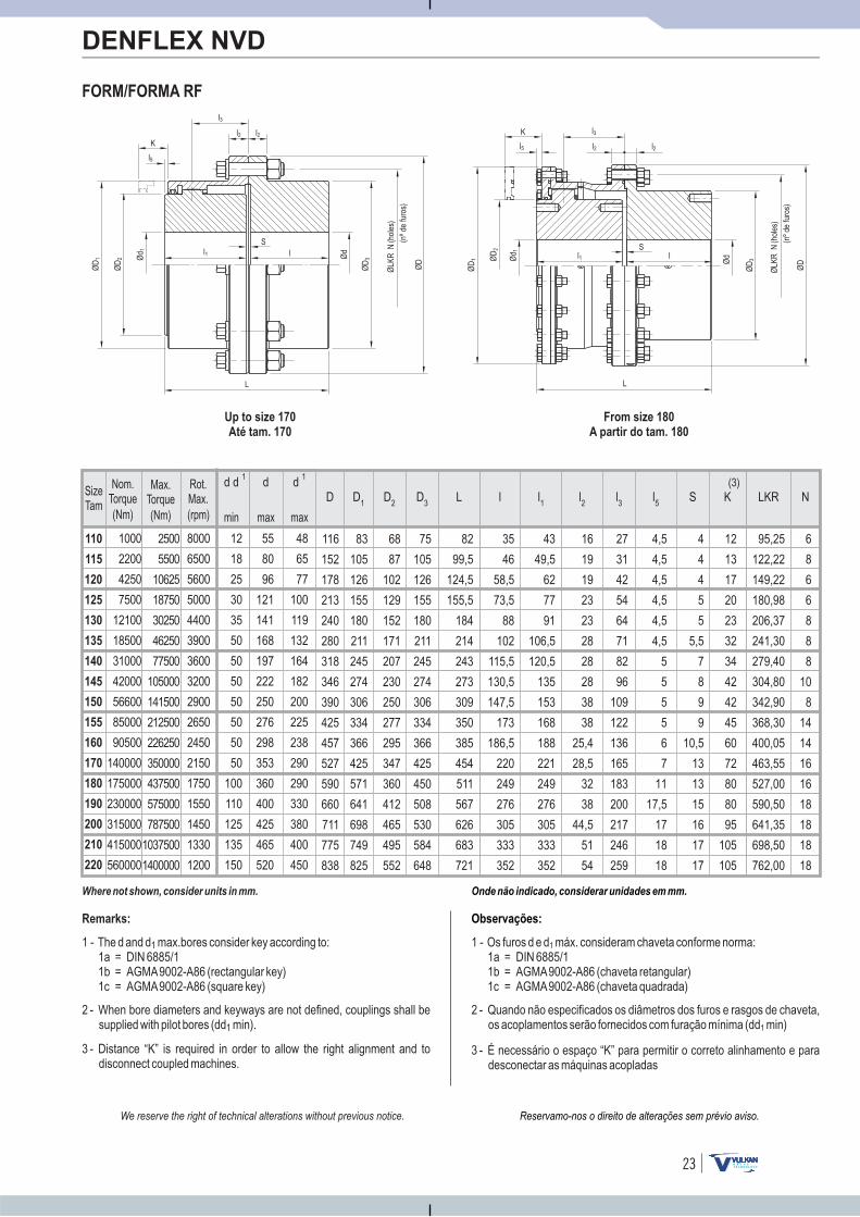
110
115
120
125
130
135
140
145
150
155
160
170
180
190
200
210
220
12
18
25
30
35
50
50
50
50
50
50
50
100
110
125
135
150
1000
2200
4250
7500
12100
18500
31000
42000
56600
85000
90500
140000
175000
230000
315000
415000
560000
8000
6500
5600
5000
4400
3900
3600
3200
2900
2650
2450
2150
1750
1550
1450
1330
1200
2500
5500
10625
18750
30250
46250
77500
105000
141500
212500
226250
350000
437500
575000
787500
1037500
1400000
55
80
96
121
141
168
197
222
250
276
298
353
360
400
425
465
520
d d 1 d 1d
48
65
77
100
119
132
164
182
200
225
238
290
290
330
380
400
450
23
43
49,5
62
77
91
106,5
120,5
135
153
168
188
221
249
276
305
333
352
l1
16
19
19
23
23
28
28
28
38
38
25,4
28,5
32
38
44,5
51
54
l2
27
31
42
54
64
71
82
96
109
122
136
165
183
200
217
246
259
l3
6
8
6
6
8
8
8
10
8
14
14
16
16
18
18
18
18
N
4,5
4,5
4,5
4,5
4,5
4,5
5
5
5
5
6
7
11
17,5
17
18
18
l5
4
4
4
5
5
5,5
7
8
9
9
10,5
13
13
15
16
17
17
S
95,25
122,22
149,22
180,98
206,37
241,30
279,40
304,80
342,90
368,30
400,05
463,55
527,00
590,50
641,35
698,50
762,00
LKR
12
13
17
20
23
32
34
42
42
45
60
72
80
80
95
105
105
K(3)
35
46
58,5
73,5
88
102
115,5
130,5
147,5
173
186,5
220
249
276
305
333
352
l
83
105
126
155
180
211
245
274
306
334
366
425
571
641
698
749
825
68
87
102
129
152
171
207
230
250
277
295
347
360
412
465
495
552
75
105
126
155
180
211
245
274
306
334
366
425
450
508
530
584
648
D2
D3
D1
116
152
178
213
240
280
318
346
390
425
457
527
590
660
711
775
838
D
FORM/FORMA RF
DENFLEX NVD
Onde não indicado, considerar unidades em mm.
82
99,5
124,5
155,5
184
214
243
273
309
350
385
454
511
567
626
683
721
L
Observações:
1 - Os furos d e d máx. consideram chaveta conforme norma:1a = DIN 6885/11b = AGMA9002-A86 (chaveta retangular)1c = AGMA9002-A86 (chaveta quadrada)
1
2 - Quando não especificados os diâmetros dos furos e rasgos de chaveta,os acoplamentos serão fornecidos com furação mínima (dd min)1
3 - É necessário o espaço “K” para permitir o correto alinhamento e paradesconectar as máquinas acopladas
Up to size 170
Até tam. 170
From size 180
A partir do tam. 180
Ød
K
l1S
l
LØ
LKR
N
(nºd
e)
furo
s
(hol
es)
ØD
3
ØD
ØD
2
ØD
1 Ød 1
K
ØD
2
Ød 1 l1
Sl
L
ØLK
RN
(nºd
e)
furo
s
(hol
es)
ØD
3
ØD
ØD
1 Ød
l5
l3
l2
l5
l3
l2
l2
l2
Reservamo-nos o direito de alterações sem prévio aviso.We reserve the right of technical alterations without previous notice.
Where not shown, consider units in mm.
Remarks:
1 - The d and d max.bores :1a = DIN 6885/11b = AGMA9002-A86 (rectangular key)1c = AGMA9002-A86 (square key)
1 consider key according to
2 - When bore diameters and keyways are not defined, couplings shall besupplied with pilot bores (dd min).1
3 - Distance “K” is required in order to allow the right alignment and todisconnect coupled machines.
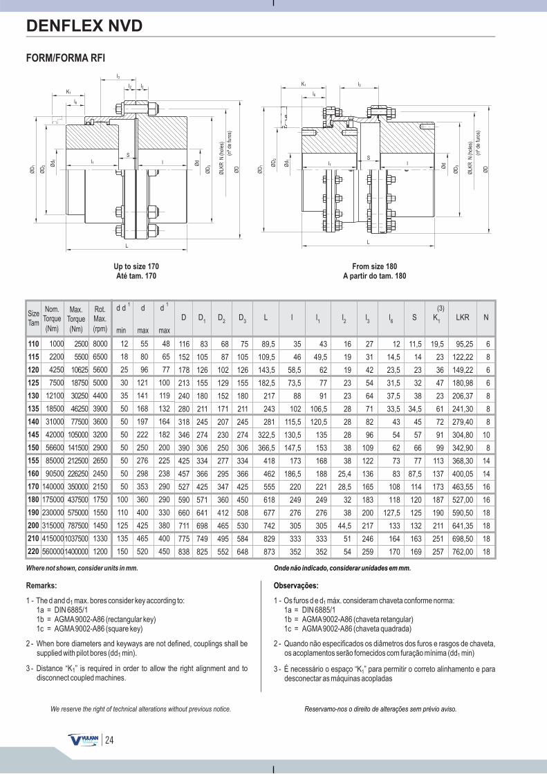
110
115
120
125
130
135
140
145
150
155
160
170
180
190
200
210
220
12
18
25
30
35
50
50
50
50
50
50
50
100
110
125
135
150
1000
2200
4250
7500
12100
18500
31000
42000
56600
85000
90500
140000
175000
230000
315000
415000
560000
8000
6500
5600
5000
4400
3900
3600
3200
2900
2650
2450
2150
1750
1550
1450
1330
1200
2500
5500
10625
18750
30250
46250
77500
105000
141500
212500
226250
350000
437500
575000
787500
1037500
1400000
55
80
96
121
141
168
197
222
250
276
298
353
360
400
425
465
520
d d 1 d 1d
48
65
77
100
119
132
164
182
200
225
238
290
290
330
380
400
450
24
FORM/FORMA RFI
DENFLEX NVD
43
49,5
62
77
91
106,5
120,5
135
153
168
188
221
249
276
305
333
352
l1
16
19
19
23
23
28
28
28
38
38
25,4
28,5
32
38
44,5
51
54
l2
27
31
42
54
64
71
82
96
109
122
136
165
183
200
217
246
259
l3
6
8
6
6
8
8
8
10
8
14
14
16
16
18
18
18
18
N
12
14,5
23,5
31,5
37,5
33,5
43
54
62
73
83
108
118
127,5
133
164
170
l6
11,5
14
23
32
38
34,5
45
57
66
77
87,5
114
120
125
132
163
169
S
95,25
122,22
149,22
180,98
206,37
241,30
279,40
304,80
342,90
368,30
400,05
463,55
527,00
590,50
641,35
698,50
762,00
LKR
19,5
23
36
47
23
61
72
91
99
113
137
173
187
190
211
251
257
(3)
35
46
58,5
73,5
88
102
115,5
130,5
147,5
173
186,5
220
249
276
305
333
352
l
83
105
126
155
180
211
245
274
306
334
366
425
571
641
698
749
825
68
87
102
129
152
171
207
230
250
277
295
347
360
412
465
495
552
75
105
126
155
180
211
245
274
306
334
366
425
450
508
530
584
648
D2
D3
D1
116
152
178
213
240
280
318
346
390
425
457
527
590
660
711
775
838
D
Onde não indicado, considerar unidades em mm.
89,5
109,5
143,5
182,5
217
243
281
322,5
366,5
418
462
555
618
677
742
829
873
L
Observações:
1 - Os furos d e d máx. consideram chaveta conforme norma:1a = DIN 6885/11b = AGMA9002-A86 (chaveta retangular)1c = AGMA9002-A86 (chaveta quadrada)
1
2 - Quando não especificados os diâmetros dos furos e rasgos de chaveta,os acoplamentos serão fornecidos com furação mínima (dd min)1
3 - É necessário o espaço “K ” para permitir o correto alinhamento e paradesconectar as máquinas acopladas
1
Up to size 170
Até tam. 170
From size 180
A partir do tam. 180
K1
Ød
K1
l1S
l
L
ØLK
RN
(nºd
e)
furo
s
(hol
es)
ØD
3
ØD
ØD
2
ØD
1 Ød 1
K1
ØD
2
Ød 1 l1
Sl
L
ØLK
RN
(nºd
e)
furo
s
(hol
es)
ØD
3
ØD
ØD
1 Ød
l3
l2 l2
l6
l3
l6
Reservamo-nos o direito de alterações sem prévio aviso.We reserve the right of technical alterations without previous notice.
Where not shown, consider units in mm.
Remarks:
1 - The d and d max. bores :1a = DIN 6885/11b = AGMA9002-A86 (rectangular key)1c = AGMA9002-A86 (square key)
1 consider key according to
2 - When bore diameters and keyways are not defined, couplings shall besupplied with pilot bores (dd min).1
3 - Distance “K ” is required in order to allow the right alignment and todisconnect coupled machines.
1
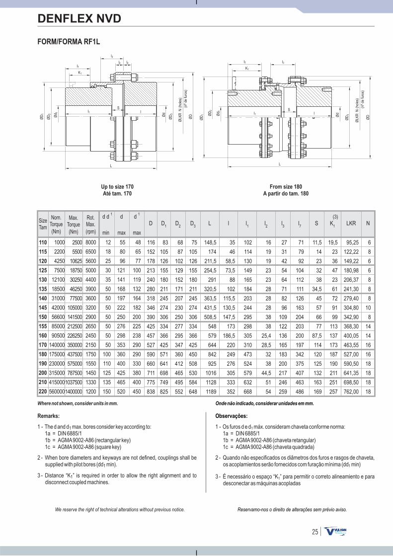
110
115
120
125
130
135
140
145
150
155
160
170
180
190
200
210
220
12
18
25
30
35
50
50
50
50
50
50
50
100
110
125
135
150
1000
2200
4250
7500
12100
18500
31000
42000
56600
85000
90500
140000
175000
230000
315000
415000
560000
8000
6500
5600
5000
4400
3900
3600
3200
2900
2650
2450
2150
1750
1550
1450
1330
1200
2500
5500
10625
18750
30250
46250
77500
105000
141500
212500
226250
350000
437500
575000
787500
1037500
1400000
55
80
96
121
141
168
197
222
250
276
298
353
360
400
425
465
520
d d 1 d 1d
48
65
77
100
119
132
164
182
200
225
238
290
290
330
380
400
450
25
102
114
130
149
165
184
203
244
295
298
305
310
473
524
579
632
668
l1
16
19
19
23
23
28
28
28
38
38
25,4
28,5
32
38
44,5
51
54
l2
27
31
42
54
64
71
82
96
109
122
136
165
183
200
217
246
259
l3
6
8
6
6
8
8
8
10
8
14
14
16
16
18
18
18
18
N
71
79
92
104
112
111
126
163
204
203
200
197
342
375
407
463
486
l7
11,5
14
23
32
38
34,5
45
57
66
77
87,5
114
120
125
132
163
169
S
95,25
122,22
149,22
180,98
206,37
241,30
279,40
304,80
342,90
368,30
400,05
463,55
527,00
590,50
641,35
698,50
762,00
LKR
19,5
23
36
47
23
61
72
91
99
113
137
173
187
190
211
251
257
(3)
35
46
58,5
73,5
88
102
115,5
130,5
147,5
173
186,5
220
249
276
305
333
352
l
83
105
126
155
180
211
245
274
306
334
366
425
571
641
698
749
825
68
87
102
129
152
171
207
230
250
277
295
347
360
412
465
495
552
75
105
126
155
180
211
245
274
306
334
366
425
450
508
530
584
648
D2
D3
D1
116
152
178
213
240
280
318
346
390
425
457
527
590
660
711
775
838
D
FORM/FORMA RF1L
DENFLEX NVD
Onde não indicado, considerar unidades em mm.
148,5
174
211,5
254,5
291
320,5
363,5
431,5
508,5
548
579
644
842
925
1016
1128
1189
L
Observações:
1 - Os furos d e d máx. consideram chaveta conforme norma:1a = DIN 6885/11b = AGMA9002-A86 (chaveta retangular)1c = AGMA9002-A86 (chaveta quadrada)
1
2 - Quando não especificados os diâmetros dos furos e rasgos de chaveta,os acoplamientos serão fornecidos com furação mínima (dd min)1
3 - É necessário o espaço “K ” para permitir o correto alineamiento e paradesconectar as máquinas acopladas
1
Up to size 170
Até tam. 170
From size 180
A partir do tam. 180
K1
Ød
K1
l1S
l
L
ØLK
RN
(nºd
e)
furo
s
(hol
es)
ØD
3
ØD
ØD
2
ØD
1
Ød 1
K1
ØD
2
Ød 1 l1
Sl
L
ØLK
RN
(nºd
e)
furo
s
(hol
es)
ØD
3
ØD
ØD
1 Ød
l3
l2 l2l7
l3l7
Reservamo-nos o direito de alterações sem prévio aviso.We reserve the right of technical alterations without previous notice.
Where not shown, consider units in mm.
Remarks:
1 - The d and d max. bores :1a = DIN 6885/11b = AGMA9002-A86 (rectangular key)1c = AGMA9002-A86 (square key)
1 consider key according to
2 - When bore diameters and keyways are not defined, couplings shall besupplied with pilot bores (dd min).1
3 - Distance “K ” is required in order to allow the right alignment and todisconnect coupled machines.
1
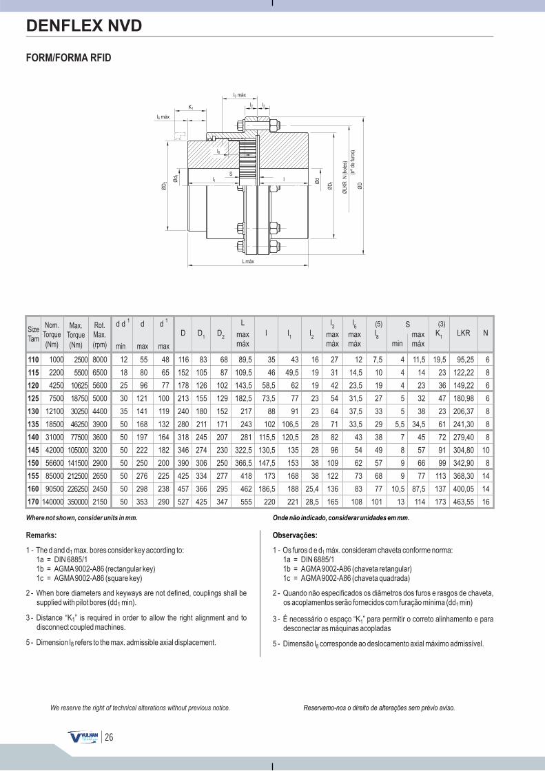
110
115
120
125
130
135
140
145
150
155
160
170
12
18
25
30
35
50
50
50
50
50
50
50
1000
2200
4250
7500
12100
18500
31000
42000
56600
85000
90500
140000
8000
6500
5600
5000
4400
3900
3600
3200
2900
2650
2450
2150
2500
5500
10625
18750
30250
46250
77500
105000
141500
212500
226250
350000
55
80
96
121
141
168
197
222
250
276
298
353
d d 1 d 1d
48
65
77
100
119
132
164
182
200
225
238
290
26
7,5
10
19
27
33
29
38
49
57
68
77
101
l8
4
4
4
5
5
5,5
7
8
9
9
10,5
13
S
min
11,5
14
23
32
38
34,5
45
57
66
77
87,5
114
89,5
109,5
143,5
182,5
217
243
281
322,5
366,5
418
462
555
L
FORM/FORMA RFID
Reservamo-nos o direito de alterações sem prévio aviso.
DENFLEX NVD
6
8
6
6
8
8
8
10
8
14
14
16
N
27
31
42
54
64
71
82
96
109
122
136
165
l3
12
14,5
23,5
31,5
37,5
33,5
43
54
62
73
83
108
l6
95,25
122,22
149,22
180,98
206,37
241,30
279,40
304,80
342,90
368,30
400,05
463,55
LKR
19,5
23
36
47
23
61
72
91
99
113
137
173
(3)(5)
43
49,5
62
77
91
106,5
120,5
135
153
168
188
221
l1
16
19
19
23
23
28
28
28
38
38
25,4
28,5
l2
35
46
58,5
73,5
88
102
115,5
130,5
147,5
173
186,5
220
l
83
105
126
155
180
211
245
274
306
334
366
425
68
87
102
129
152
171
207
230
250
277
295
347
D2
D1
116
152
178
213
240
280
318
346
390
425
457
527
D
Onde não indicado, considerar unidades em mm.
Observações:
1 - Os furos d e d máx. consideram chaveta conforme norma:1a = DIN 6885/11b = AGMA9002-A86 (chaveta retangular)1c = AGMA9002-A86 (chaveta quadrada)
1
2 - Quando não especificados os diâmetros dos furos e rasgos de chaveta,os acoplamentos serão fornecidos com furação mínima (dd min)1
3 - É necessário o espaço “K ” para permitir o correto alinhamento e paradesconectar as máquinas acopladas
1
K1max
máxmaxmáx
maxmáx
5 - Dimensão l corresponde ao deslocamento axial máximo admissível.8
Ød 1
K1
l1S
L máx
ØD
2
ØLK
RN
(nºd
e)
furo
s
(hol
es)
ØD
1
ØD
l Ød
l2 l2
l8
l6 máx
l3 máx
maxmáx
We reserve the right of technical alterations without previous notice.
Where not shown, consider units in mm.
Remarks:
1 - The d and d max. bores :1a = DIN 6885/11b = AGMA9002-A86 (rectangular key)1c = AGMA9002-A86 (square key)
1 consider key according to
2 - When bore diameters and keyways are not defined, couplings shall besupplied with pilot bores (dd min).1
3 - Distance “K ” is required in order to allow the right alignment and todisconnect coupled machines.
1
5 - Dimension l refers to the max. admissible axial .8 displacement
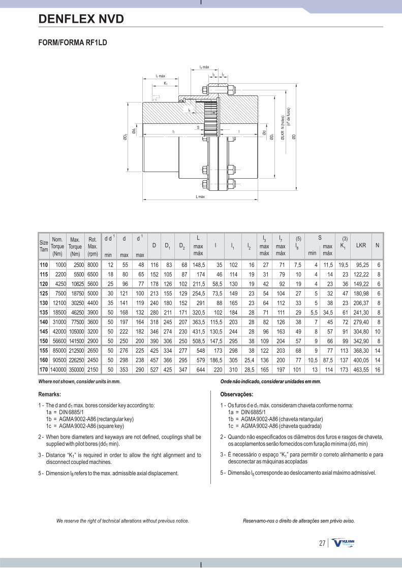
110
115
120
125
130
135
140
145
150
155
160
170
12
18
25
30
35
50
50
50
50
50
50
50
1000
2200
4250
7500
12100
18500
31000
42000
56600
85000
90500
140000
8000
6500
5600
5000
4400
3900
3600
3200
2900
2650
2450
2150
2500
5500
10625
18750
30250
46250
77500
105000
141500
212500
226250
350000
55
80
96
121
141
168
197
222
250
276
298
353
d d 1 d 1d
48
65
77
100
119
132
164
182
200
225
238
290
27
FORM/FORMA RF1LD
DENFLEX NVD
7,5
10
19
27
33
29
38
49
57
68
77
101
l8
4
4
4
5
5
5,5
7
8
9
9
10,5
13
S
min
11,5
14
23
32
38
34,5
45
57
66
77
87,5
114
148,5
174
211,5
254,5
291
320,5
363,5
431,5
508,5
548
579
644
L
6
8
6
6
8
8
8
10
8
14
14
16
N
27
31
42
54
64
71
82
96
109
122
136
165
l3
71
79
92
104
112
111
126
163
204
203
200
197
l7
95,25
122,22
149,22
180,98
206,37
241,30
279,40
304,80
342,90
368,30
400,05
463,55
LKR
19,5
23
36
47
23
61
72
91
99
113
137
173
(3)(5)
102
114
130
149
165
184
203
244
295
298
305
310
l1
16
19
19
23
23
28
28
28
38
38
25,4
28,5
l2
35
46
58,5
73,5
88
102
115,5
130,5
147,5
173
186,5
220
l
83
105
126
155
180
211
245
274
306
334
366
425
68
87
102
129
152
171
207
230
250
277
295
347
D2
D1
116
152
178
213
240
280
318
346
390
425
457
527
D
Onde não indicado, considerar unidades em mm.
Observações:
1 - Os furos d e d máx. consideram chaveta conforme norma:1a = DIN 6885/11b = AGMA9002-A86 (chaveta retangular)1c = AGMA9002-A86 (chaveta quadrada)
1
2 - Quando não especificados os diâmetros dos furos e rasgos de chaveta,os acoplamentos serão fornecidos com furação mínima (dd min)1
3 - É necessário o espaço “K ” para permitir o correto alinhamento e paradesconectar as máquinas acopladas
1
K1max
máxmaxmáx
maxmáx
maxmáx
5 - Dimensão l corresponde ao deslocamento axial máximo admissível.8
Ød 1
K1
l1S
L máx
ØD
2
ØLK
RN
(nºd
e)
furo
s
(hol
es)
ØD
1
ØD
l Ød
l2 l2
l8
l7 máx
l3 máx
Reservamo-nos o direito de alterações sem prévio aviso.We reserve the right of technical alterations without previous notice.
Where not shown, consider units in mm.
Remarks:
1 - The d and d max. bores :1a = DIN 6885/11b = AGMA9002-A86 (rectangular key)1c = AGMA9002-A86 (square key)
1 consider key according to
2 - When bore diameters and keyways are not defined, couplings shall besupplied with pilot bores (dd min).1
3 - Distance “K ” is required in order to allow the right alignment and todisconnect coupled machines.
1
5 - Dimension l refers to the max. admissible axial .8 displacement
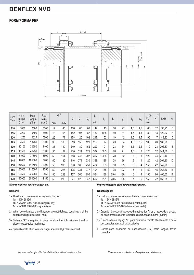
SizeTam.
min max
d 1)
(Nm)
Max.Torque
(Nm)
Nom.Torque
(rpm)
Rot.Max.
48
65
77
100
119
132
164
182
200
225
238
290
12
18
25
30
35
50
50
50
50
50
50
50
110
115
120
125
130
135
140
145
150
155
160
170
1000
2200
4250
7500
12100
18500
31000
42000
56600
85000
90500
140000
2500
5500
10625
18750
30250
46250
77500
105000
141500
212500
226250
350000
8000
6500
5600
5000
4400
3900
3600
3200
2900
2650
2450
2150
28
FORM/FORMA FEF
Reservamo-nos o direito de alterações sem prévio aviso.
DENFLEX NVD
Onde não indicado, considerar unidades em mm.
Observações:
1 - Os furos d máx. consideram chaveta conforme norma:1a = DIN 6885/11b = AGMA9002-A86 (chaveta retangular)1c = AGMA9002-A86 (chaveta quadrada)
1
2 - Quando não especificados os diâmetros dos furos e rasgos de chaveta,os acoplamentos serão fornecidos com furação mínima (d min)1
3 - É necessário o espaço “K” para permitir o correto alinhamento e paradesconectar as máquinas acopladas
4 - Construções especiais ou espaçadores (S2) mais longos, favorconsultar
K
S (mín)2
ØD
2
ØLK
RN
(nºd
e)
furo
s
(hol
es)
L (mín)1
ØD
ØD
1
Ød 1
S1
l1S1
l1
l5
l3
l2l2
We reserve the right of technical alterations without previous notice.
Where not shown, consider units in mm.
Remarks:
1 - The d max. bores :1a = DIN 6885/11b = AGMA9002-A86 (rectangular key)1c = AGMA9002-A86 (square key)
1 consider key according to
2 - When bore diameters and keyways are not defined, couplings shall besupplied with pilot bores (d min).1
3 - Distance “K” is required in order to allow the right alignment and todisconnect coupled machines.
4 - Special construction forms or longer spacers (S ), please consult.2
60
80
90
100
110
120
120
120
150
150
150
150
1,5
1,5
1,5
2,5
2,5
3
3
4
4
4
4
5
12
13
17
20
23
32
34
42
42
45
60
72
116
152
178
213
240
280
318
346
390
425
457
527
83
105
126
155
180
211
245
274
306
334
366
425
68
87
102
129
152
171
207
230
250
277
295
347
149
182
217
259
297
339
367
398
464
494
534
602
43
49,5
62
77
91
106,5
120,5
135
153
168
188
221
16
19
19
23
23
28
28
28
38
38
25,4
28,5
27
31
42
54
64
71
82
96
109
122
136
165
4,5
4,5
4,5
4,5
4,5
4,5
5
5
5
5
6
7
95,25
122,22
149,22
180,98
206,37
241,30
279,40
304,80
342,90
368,30
400,05
463,55
6
8
6
6
8
8
8
10
8
14
14
16
S1K
(3)D D
2D
1l1
l2
l3
l5
LKR Nmin min
L1 S
2
(4)
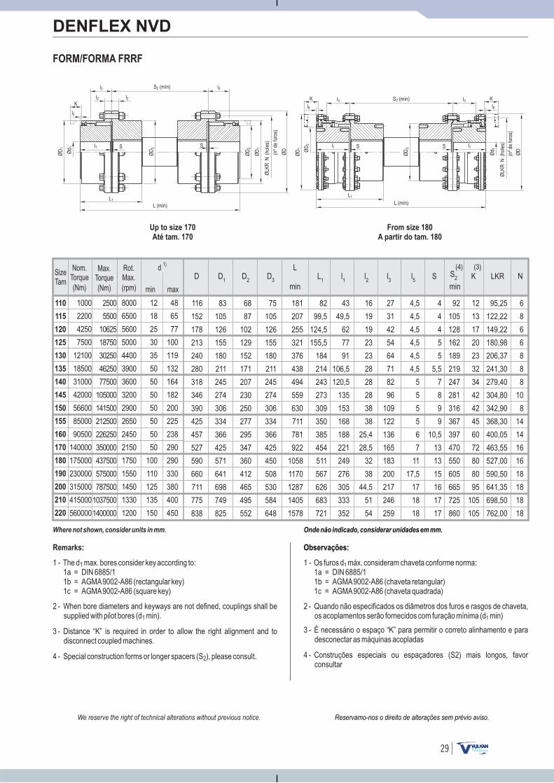
110
115
120
125
130
135
140
145
150
155
160
170
180
190
200
210
220
12
18
25
30
35
50
50
50
50
50
50
50
100
110
125
135
150
1000
2200
4250
7500
12100
18500
31000
42000
56600
85000
90500
140000
175000
230000
315000
415000
560000
8000
6500
5600
5000
4400
3900
3600
3200
2900
2650
2450
2150
1750
1550
1450
1330
1200
2500
5500
10625
18750
30250
46250
77500
105000
141500
212500
226250
350000
437500
575000
787500
1037500
1400000
48
65
77
100
119
132
164
182
200
225
238
290
290
330
380
400
450
29
Onde não indicado, considerar unidades em mm.
Observações:
1 - Os furos d máx. consideram chaveta conforme norma:1a = DIN 6885/11b = AGMA9002-A86 (chaveta retangular)1c = AGMA9002-A86 (chaveta quadrada)
1
2 - Quando não especificados os diâmetros dos furos e rasgos de chaveta,os acoplamentos serão fornecidos com furação mínima (d min)1
3 - É necessário o espaço “K” para permitir o correto alinhamento e paradesconectar as máquinas acopladas
4 - Construções especiais ou espaçadores (S2) mais longos, favorconsultar
FORM/FORMA FRRF
DENFLEX NVD
Up to size 170
Até tam. 170
From size 180
A partir do tam. 180
K
l1 S
L1
L (mín)
ØLK
RN
(nºd
e)
furo
s
(hol
es)
ØD
3
ØD
ØD
1
Ød 1
S (mín)2
S
ØD
2
ØD
1
K
ØD
2
Ød 1
l1 S
L1
L (mín)
ØLK
RN
(nºd
e)
furo
s
(hol
es)
ØD
ØD
1
ØD
3
KS (mín)2
l1S
l5
l3
l2
l5
l3l2
l3
l3l5
Where not shown, consider units in mm.
Remarks:
1 - The d max. bores :1a = DIN 6885/11b = AGMA9002-A86 (rectangular key)1c = AGMA9002-A86 (square key)
1 consider key according to
2 - When bore diameters and keyways are not defined, couplings shall besupplied with pilot bores (d min).1
3 - Distance “K” is required in order to allow the right alignment and todisconnect coupled machines.
4 - Special construction forms or longer spacers (S ), please consult.2
Reservamo-nos o direito de alterações sem prévio aviso.We reserve the right of technical alterations without previous notice.
16
19
19
23
23
28
28
28
38
38
25,4
28,5
32
38
44,5
51
54
27
31
42
54
64
71
82
96
109
122
136
165
183
200
217
246
259
6
8
6
6
8
8
8
10
8
14
14
16
16
18
18
18
18
4,5
4,5
4,5
4,5
4,5
4,5
5
5
5
5
6
7
11
17,5
17
18
18
4
4
4
5
5
5,5
7
8
9
9
10,5
13
13
15
16
17
17
92
105
128
162
189
219
247
281
316
367
397
470
550
605
665
725
860
95,25
122,22
149,22
180,98
206,37
241,30
279,40
304,80
342,90
368,30
400,05
463,55
527,00
590,50
641,35
698,50
762,00
12
13
17
20
23
32
34
42
42
45
60
72
80
80
95
105
105
43
49,5
62
77
91
106,5
120,5
135
153
168
188
221
249
276
305
333
352
83
105
126
155
180
211
245
274
306
334
366
425
571
641
698
749
825
68
87
102
129
152
171
207
230
250
277
295
347
360
412
465
495
552
75
105
126
155
180
211
245
274
306
334
366
425
450
508
530
584
648
116
152
178
213
240
280
318
346
390
425
457
527
590
660
711
775
838
82
99,5
124,5
155,5
184
214
243
273
309
350
385
454
511
567
626
683
721
181
207
255
321
376
438
494
559
630
711
781
922
1058
1170
1287
1405
1578
LKRS K(3)
D D2
D3
D1
l1
l2
l3
l5
Nmin min
LS
2
(4)L
1
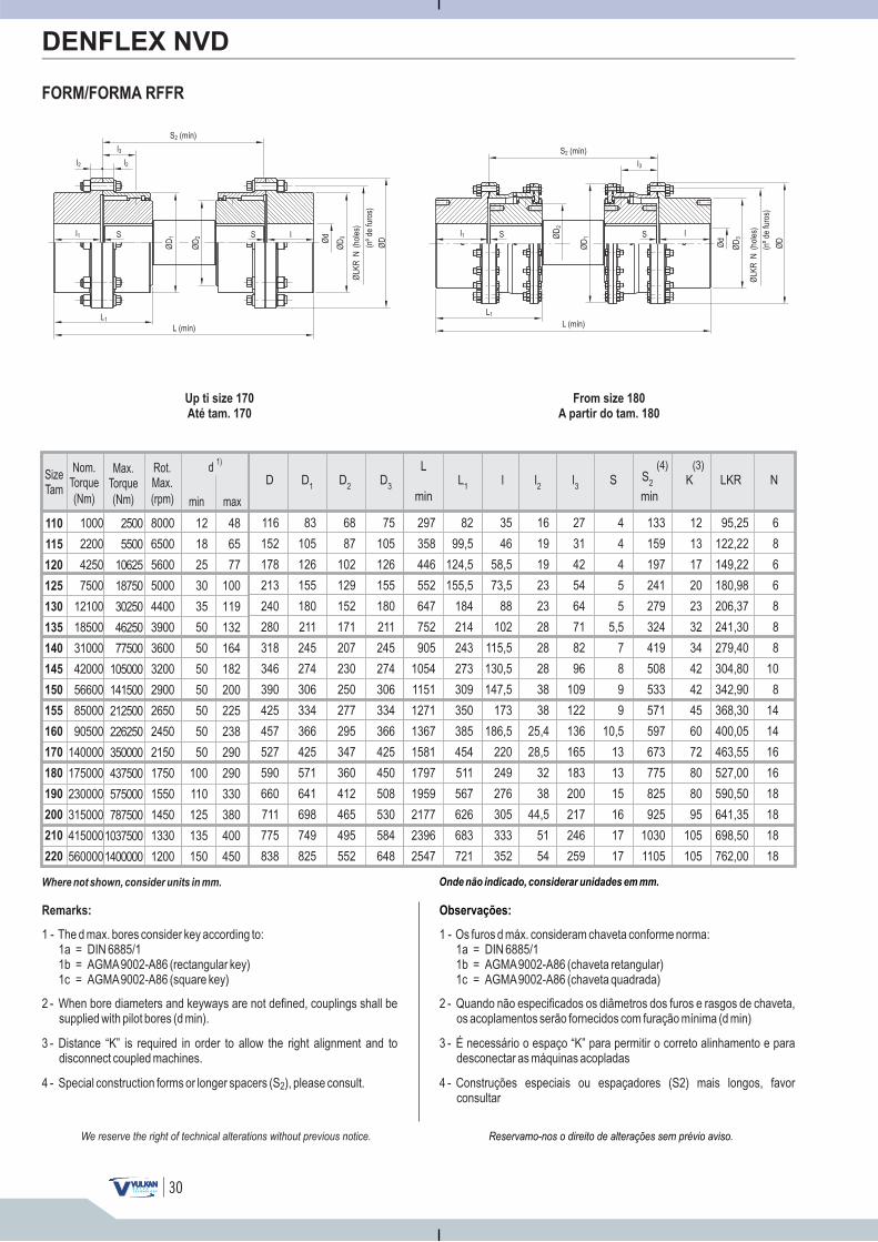
110
115
120
125
130
135
140
145
150
155
160
170
180
190
200
210
220
12
18
25
30
35
50
50
50
50
50
50
50
100
110
125
135
150
1000
2200
4250
7500
12100
18500
31000
42000
56600
85000
90500
140000
175000
230000
315000
415000
560000
8000
6500
5600
5000
4400
3900
3600
3200
2900
2650
2450
2150
1750
1550
1450
1330
1200
2500
5500
10625
18750
30250
46250
77500
105000
141500
212500
226250
350000
437500
575000
787500
1037500
1400000
48
65
77
100
119
132
164
182
200
225
238
290
290
330
380
400
450
30
Onde não indicado, considerar unidades em mm.
Observações:
1 - Os furos d máx. consideram chaveta conforme norma:1a = DIN 6885/11b = AGMA9002-A86 (chaveta retangular)1c = AGMA9002-A86 (chaveta quadrada)
2 - Quando não especificados os diâmetros dos furos e rasgos de chaveta,os acoplamentos serão fornecidos com furação mínima (d min)
3 - É necessário o espaço “K” para permitir o correto alinhamento e paradesconectar as máquinas acopladas
4 - Construções especiais ou espaçadores (S2) mais longos, favorconsultar
FORM/FORMA RFFR
DENFLEX NVD
Up ti size 170
Até tam. 170
From size 180
A partir do tam. 180
l1 S
L1
L (mín)
ØLK
RN
(nºd
e)
furo
s
(hol
es)
ØD
1
ØD
S (mín)2
S
ØD
2
ØD
3l
Ød
Ød
l1 S
L1
L (mín)
ØLK
RN
(nºd
e)
furo
s
(hol
es)
ØD
ØD
1
S (mín)2
lSØD
2
ØD
3
l2 l3l2
l3
Reservamo-nos o direito de alterações sem prévio aviso.We reserve the right of technical alterations without previous notice.
Where not shown, consider units in mm.
Remarks:
1 - The d max. bores :1a = DIN 6885/11b = AGMA9002-A86 (rectangular key)1c = AGMA9002-A86 (square key)
consider key according to
2 - When bore diameters and keyways are not defined, couplings shall besupplied with pilot bores (d min).
3 - Distance “K” is required in order to allow the right alignment and todisconnect coupled machines.
4 - Special construction forms or longer spacers (S ), please consult.2
16
19
19
23
23
28
28
28
38
38
25,4
28,5
32
38
44,5
51
54
27
31
42
54
64
71
82
96
109
122
136
165
183
200
217
246
259
35
46
58,5
73,5
88
102
115,5
130,5
147,5
173
186,5
220
249
276
305
333
352
6
8
6
6
8
8
8
10
8
14
14
16
16
18
18
18
18
4
4
4
5
5
5,5
7
8
9
9
10,5
13
13
15
16
17
17
133
159
197
241
279
324
419
508
533
571
597
673
775
825
925
1030
1105
95,25
122,22
149,22
180,98
206,37
241,30
279,40
304,80
342,90
368,30
400,05
463,55
527,00
590,50
641,35
698,50
762,00
12
13
17
20
23
32
34
42
42
45
60
72
80
80
95
105
105
83
105
126
155
180
211
245
274
306
334
366
425
571
641
698
749
825
68
87
102
129
152
171
207
230
250
277
295
347
360
412
465
495
552
75
105
126
155
180
211
245
274
306
334
366
425
450
508
530
584
648
116
152
178
213
240
280
318
346
390
425
457
527
590
660
711
775
838
82
99,5
124,5
155,5
184
214
243
273
309
350
385
454
511
567
626
683
721
297
358
446
552
647
752
905
1054
1151
1271
1367
1581
1797
1959
2177
2396
2547
l l2 l3
LKRS K(3)
D D2
D3
D1
Nmin min
LS
2
(4)L
1
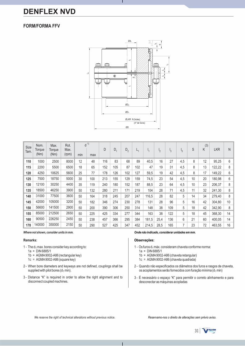
SizeTam.
min max
d 1)
(Nm)
Max.Torque
(Nm)
Nom.Torque
(rpm)
Rot.Max.
48
65
77
100
119
132
164
182
200
225
238
290
12
18
25
30
35
50
50
50
50
50
50
50
110
115
120
125
130
135
140
145
150
155
160
170
1000
2200
4250
7500
12100
18500
31000
42000
56600
85000
90500
140000
2500
5500
10625
18750
30250
46250
77500
105000
141500
212500
226250
350000
8000
6500
5600
5000
4400
3900
3600
3200
2900
2650
2450
2150
31
Onde não indicado, considerar unidades em mm.
FORM/FORMA FFV
DENFLEX NVD
Observações:
1 - Os furos d máx. consideram chaveta conforme norma:1a = DIN 6885/11b = AGMA9002-A86 (chaveta retangular)1c = AGMA9002-A86 (chaveta quadrada)
1
2 - Quando não especificados os diâmetros dos furos e rasgos de chaveta,os acoplamentos serão fornecidos com furação mínima (d min)1
3 - É necessário o espaço “K” para permitir o correto alinhamento e paradesconectar as máquinas acopladas
Ød1
K
l 1
S
l 1
L 1
ØD2
ØLKR N
(nº de )furos
(holes)
ØD1
ØD
l 5
l 3
l 2l 2
Reservamo-nos o direito de alterações sem prévio aviso.We reserve the right of technical alterations without previous notice.
Where not shown, consider units in mm.
Remarks:
1 - The d max. bores :1a = DIN 6885/11b = AGMA9002-A86 (rectangular key)1c = AGMA9002-A86 (square key)
1 consider key according to
2 - When bore diameters and keyways are not defined, couplings shall besupplied with pilot bores (d min).1
3 - Distance “K” is required in order to allow the right alignment and todisconnect coupled machines.
95,25
122,22
149,22
180,98
206,37
241,30
279,40
304,80
342,90
368,30
400,05
463,55
6
8
6
6
8
8
8
10
8
14
14
16
8
8
8
10
10
11
14
16
18
18
21
23
116
152
178
213
240
280
318
346
390
425
457
527
83
105
126
155
180
211
245
274
306
334
366
425
68
87
102
129
152
171
207
230
250
277
295
347
89
102
127
159
187
219
247
278
314
344
384
452
40,5
47
59,5
74,5
88,5
104
116,5
131
148
163
181,5
214,5
16
19
19
23
23
28
28
28
38
38
25,4
28,5
27
31
42
54
64
71
82
96
109
122
136
165
K LKR N(3)
SD D2
D1
L1
l1
l2
l3
l5
4,5
4,5
4,5
4,5
4,5
4,5
5
5
5
5
6
7
12
13
17
20
23
32
34
42
42
45
60
72
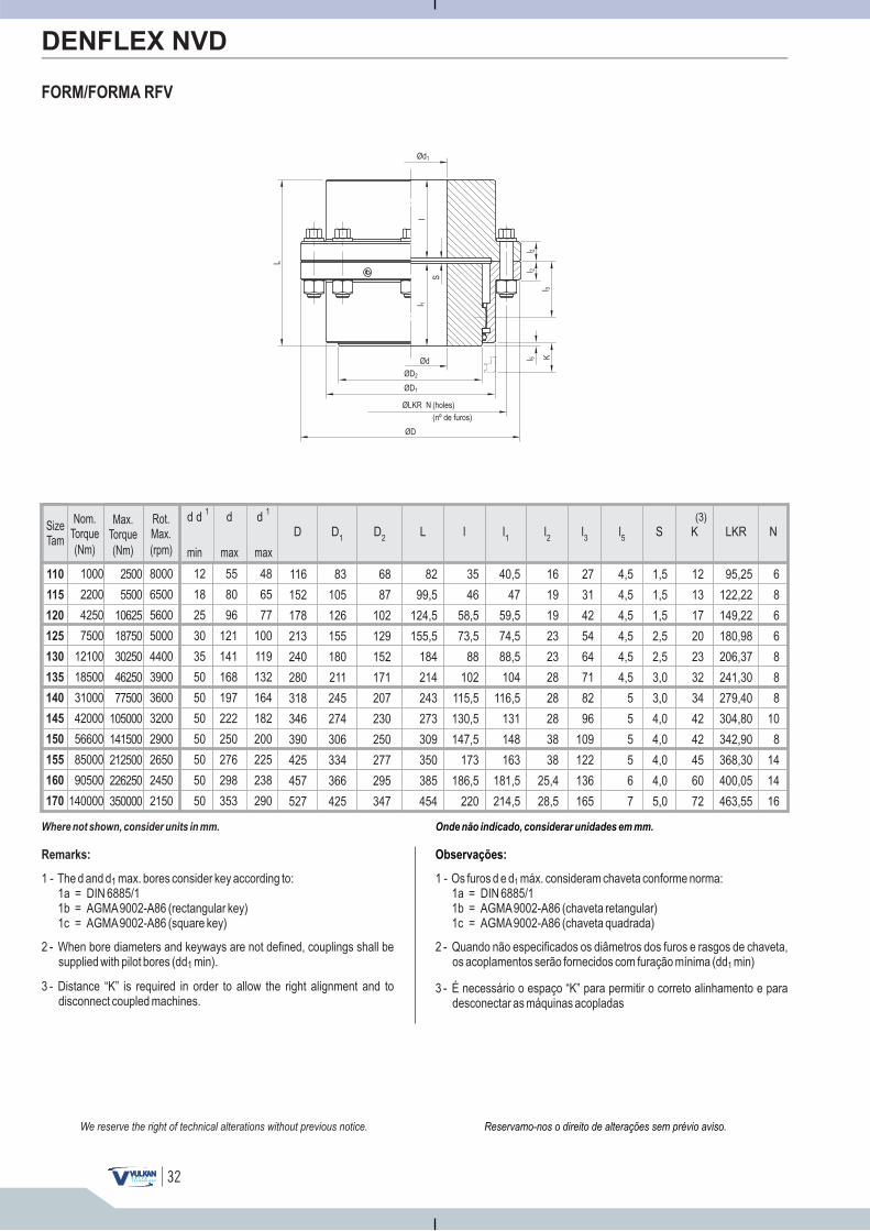
110
115
120
125
130
135
140
145
150
155
160
170
12
18
25
30
35
50
50
50
50
50
50
50
1000
2200
4250
7500
12100
18500
31000
42000
56600
85000
90500
140000
8000
6500
5600
5000
4400
3900
3600
3200
2900
2650
2450
2150
2500
5500
10625
18750
30250
46250
77500
105000
141500
212500
226250
350000
55
80
96
121
141
168
197
222
250
276
298
353
d d 1 d 1d
48
65
77
100
119
132
164
182
200
225
238
290
32
Onde não indicado, considerar unidades em mm.
FORM/FORMA RFV
DENFLEX NVD
Observações:
1 - Os furos d e d máx. consideram chaveta conforme norma:1a = DIN 6885/11b = AGMA9002-A86 (chaveta retangular)1c = AGMA9002-A86 (chaveta quadrada)
1
2 - Quando não especificados os diâmetros dos furos e rasgos de chaveta,os acoplamentos serão fornecidos com furação mínima (dd min)1
3 - É necessário o espaço “K” para permitir o correto alinhamento e paradesconectar as máquinas acopladas
Ød K
l 1
S
l
L
ØLKR N
(nº de )furos
(holes)
ØD2
ØD
Ød1
ØD1
l 5
l 3
l 2l 2
Reservamo-nos o direito de alterações sem prévio aviso.We reserve the right of technical alterations without previous notice.
Where not shown, consider units in mm.
Remarks:
1 - The d and d max. bores :1a = DIN 6885/11b = AGMA9002-A86 (rectangular key)1c = AGMA9002-A86 (square key)
1 consider key according to
2 - When bore diameters and keyways are not defined, couplings shall besupplied with pilot bores (dd min).1
3 - Distance “K” is required in order to allow the right alignment and todisconnect coupled machines.
40,5
47
59,5
74,5
88,5
104
116,5
131
148
163
181,5
214,5
16
19
19
23
23
28
28
28
38
38
25,4
28,5
27
31
42
54
64
71
82
96
109
122
136
165
6
8
6
6
8
8
8
10
8
14
14
16
4,5
4,5
4,5
4,5
4,5
4,5
5
5
5
5
6
7
1,5
1,5
1,5
2,5
2,5
3,0
3,0
4,0
4,0
4,0
4,0
5,0
95,25
122,22
149,22
180,98
206,37
241,30
279,40
304,80
342,90
368,30
400,05
463,55
12
13
17
20
23
32
34
42
42
45
60
72
35
46
58,5
73,5
88
102
115,5
130,5
147,5
173
186,5
220
82
99,5
124,5
155,5
184
214
243
273
309
350
385
454
83
105
126
155
180
211
245
274
306
334
366
425
68
87
102
129
152
171
207
230
250
277
295
347
116
152
178
213
240
280
318
346
390
425
457
527
l1 l2
l3
Nl5
S LKRK(3)
lLD2
D1
D

SizeTam.
min max
d 1)
(Nm)
Max.Torque
(Nm)
Nom.Torque
(rpm)
Rot.Max.
48
65
77
100
119
132
164
182
200
225
238
290
12
18
25
30
35
50
50
50
50
50
50
50
110
115
120
125
130
135
140
145
150
155
160
170
1000
2200
4250
7500
12100
18500
31000
42000
56600
85000
90500
140000
2500
5500
10625
18750
30250
46250
77500
105000
141500
212500
226250
350000
8000
6500
5600
5000
4400
3900
3600
3200
2900
2650
2450
2150
33
116
152
178
213
240
280
318
346
390
425
457
527
75
105
126
155
180
211
245
274
306
334
366
425
75
97
122
152
181
209
239
268
304
356
386
456
D D1
L
5
5
5
5
5
5
8
7
9
10
13
16
S
35
46
58,5
73,5
88
102
115,5
130,5
147,5
173
186,5
220
16
19
19
23
23
28
28
28
38
38
25,4
28,5
l l2
95,25
122,22
149,22
180,98
206,37
241,30
279,40
304,80
342,90
368,30
400,05
463,55
6
8
6
6
8
8
8
10
8
14
14
16
LKR N
Onde não indicado, considerar unidades em mm.
FORM/FORMA RR
DENFLEX NVD
Observações:
1 - Os furos d máx. consideram chaveta conforme norma:1a = DIN 6885/11b = AGMA9002-A86 (chaveta retangular)1c = AGMA9002-A86 (chaveta quadrada)
1
2 - Quando não especificados os diâmetros dos furos e rasgos de chaveta,os acoplamentos serão fornecidos com furação mínima (d min)1
Ød 1 l
S
l
L
ØLK
RN
(nºd
e)
furo
s
(hol
es)
ØD
1
ØD
l2 l2
Reservamo-nos o direito de alterações sem prévio aviso.We reserve the right of technical alterations without previous notice.
Where not shown, consider units in mm.
Remarks:
1 - The d max. bores :1a = DIN 6885/11b = AGMA9002-A86 (rectangular key)1c = AGMA9002-A86 (square key)
1 consider key according to
2 - When bore diameters and keyways are not defined, couplings shall besupplied with pilot bores (d min).1
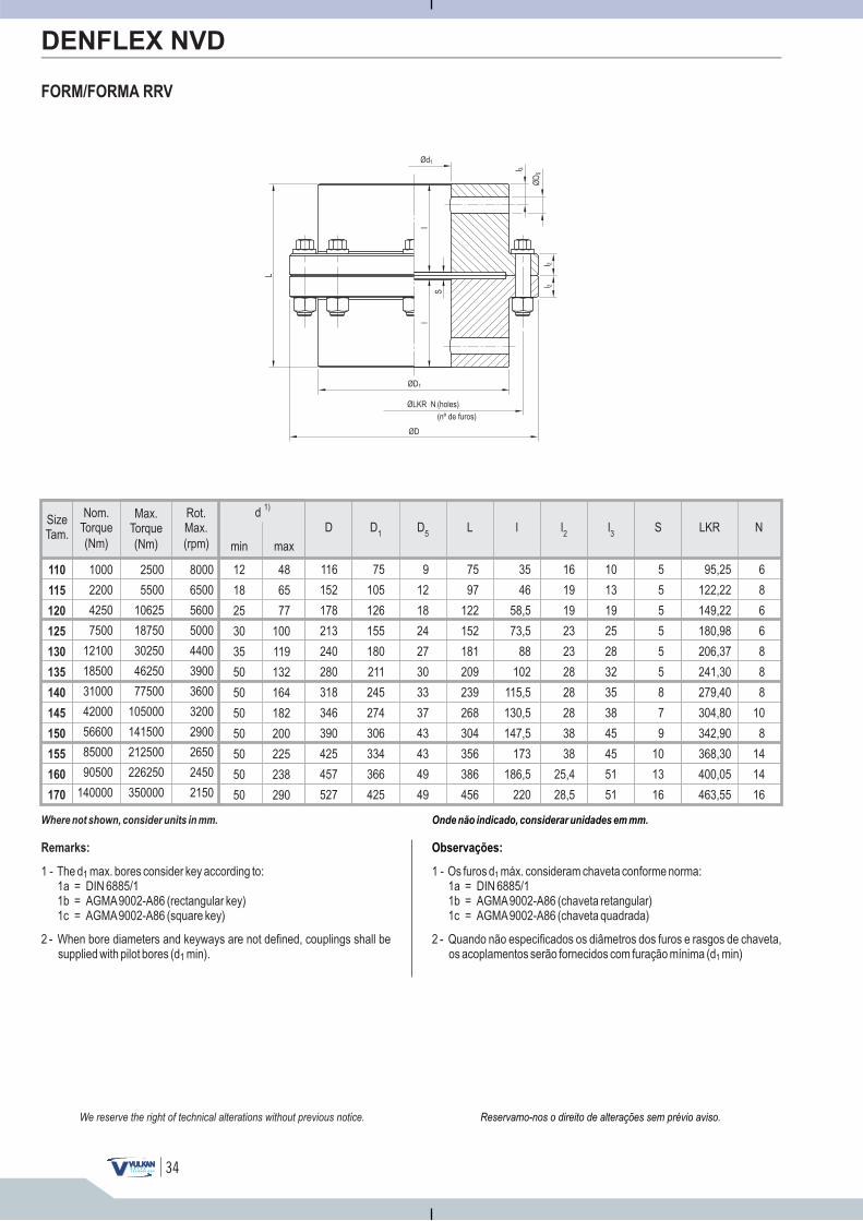
SizeTam.
min max
d 1)
(Nm)
Max.Torque
(Nm)
Nom.Torque
(rpm)
Rot.Max.
48
65
77
100
119
132
164
182
200
225
238
290
12
18
25
30
35
50
50
50
50
50
50
50
110
115
120
125
130
135
140
145
150
155
160
170
1000
2200
4250
7500
12100
18500
31000
42000
56600
85000
90500
140000
2500
5500
10625
18750
30250
46250
77500
105000
141500
212500
226250
350000
8000
6500
5600
5000
4400
3900
3600
3200
2900
2650
2450
2150
34
95,25
122,22
149,22
180,98
206,37
241,30
279,40
304,80
342,90
368,30
400,05
463,55
LKR
6
8
6
6
8
8
8
10
8
14
14
16
N
116
152
178
213
240
280
318
346
390
425
457
527
75
105
126
155
180
211
245
274
306
334
366
425
9
12
18
24
27
30
33
37
43
43
49
49
75
97
122
152
181
209
239
268
304
356
386
456
D D5
D1
L
5
5
5
5
5
5
8
7
9
10
13
16
S
35
46
58,5
73,5
88
102
115,5
130,5
147,5
173
186,5
220
16
19
19
23
23
28
28
28
38
38
25,4
28,5
10
13
19
25
28
32
35
38
45
45
51
51
l l2
l3
Onde não indicado, considerar unidades em mm.
Observações:
1 - Os furos d máx. consideram chaveta conforme norma:1a = DIN 6885/11b = AGMA9002-A86 (chaveta retangular)1c = AGMA9002-A86 (chaveta quadrada)
1
2 - Quando não especificados os diâmetros dos furos e rasgos de chaveta,os acoplamentos serão fornecidos com furação mínima (d min)1
FORM/FORMA RRV
DENFLEX NVD
Ød1
l
S
l
L
ØLKR N
(nº de )furos
(holes)
ØD1
ØD
ØD
5l 3
l 2l 2
Reservamo-nos o direito de alterações sem prévio aviso.We reserve the right of technical alterations without previous notice.
Where not shown, consider units in mm.
Remarks:
1 - The d max. bores :1a = DIN 6885/11b = AGMA9002-A86 (rectangular key)1c = AGMA9002-A86 (square key)
1 consider key according to
2 - When bore diameters and keyways are not defined, couplings shall besupplied with pilot bores (d min).1
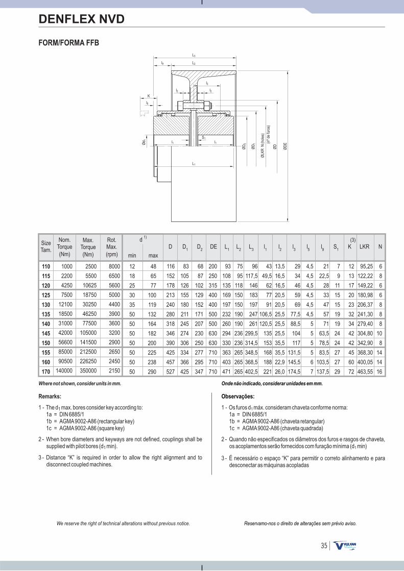
SizeTam.
min max
d 1)
(Nm)
Max.Torque
(Nm)
Nom.Torque
(rpm)
Rot.Max.
48
65
77
100
119
132
164
182
200
225
238
290
12
18
25
30
35
50
50
50
50
50
50
50
110
115
120
125
130
135
140
145
150
155
160
170
1000
2200
4250
7500
12100
18500
31000
42000
56600
85000
90500
140000
2500
5500
10625
18750
30250
46250
77500
105000
141500
212500
226250
350000
8000
6500
5600
5000
4400
3900
3600
3200
2900
2650
2450
2150
35
Onde não indicado, considerar unidades em mm.
Observações:
1 - Os furos d máx. consideram chaveta conforme norma:1a = DIN 6885/11b = AGMA9002-A86 (chaveta retangular)1c = AGMA9002-A86 (chaveta quadrada)
1
2 - Quando não especificados os diâmetros dos furos e rasgos de chaveta,os acoplamentos serão fornecidos com furação mínima (d min)1
3 - É necessário o espaço “K” para permitir o correto alinhamento e paradesconectar as máquinas acopladas
FORM/FORMA FFB
DENFLEX NVD
Ød 1
K
l1S1
l1
L1
ØD
2
ØLK
RN
(nºd
e)
furo
s
(hol
es)
ØD
1
ØD
L2
ØD
E
L3
l5
l3
l2
l9
l2
Reservamo-nos o direito de alterações sem prévio aviso.We reserve the right of technical alterations without previous notice.
Where not shown, consider units in mm.
Remarks:
1 - The d max. bores :1a = DIN 6885/11b = AGMA9002-A86 (rectangular key)1c = AGMA9002-A86 (square key)
1 consider key according to
2 - When bore diameters and keyways are not defined, couplings shall besupplied with pilot bores (d min).1
3 - Distance “K” is required in order to allow the right alignment and todisconnect coupled machines.
93
108
135
169
197
232
260
294
330
363
403
471
75
95
118
150
150
190
190
236
236
265
265
265
96
117,5
146
183
197
247
261
299,5
314,5
348,5
368,5
402,5
95,25
122,22
149,22
180,98
206,37
241,30
279,40
304,80
342,90
368,30
400,05
463,55
43
49,5
62
77
91
106,5
120,5
135
153
168
188
221
13,5
16,5
16,5
20,5
20,5
25,5
25,5
25,5
35,5
35,5
22,9
26,0
29
34
46
59
69
77,5
88,5
104
117
131,5
145,5
174,5
4,5
4,5
4,5
4,5
4,5
4,5
5
5
5
5
6
7
21
22,5
28
33
47
57
71
63,5
78,5
83,5
103,5
137,5
7
9
11
15
15
19
19
24
24
27
27
29
12
13
17
20
23
32
34
42
42
45
60
72
116
152
178
213
240
280
318
346
390
425
457
527
83
105
126
155
180
211
245
274
306
334
366
425
68
87
102
129
152
171
207
230
250
277
295
347
200
250
315
400
400
500
500
630
630
710
710
710
6
8
6
6
8
8
8
10
8
14
14
16
L1L
2L
3LKRl
1l2
l3
l5
l9
S1
K(3)
D D2
DED1
N
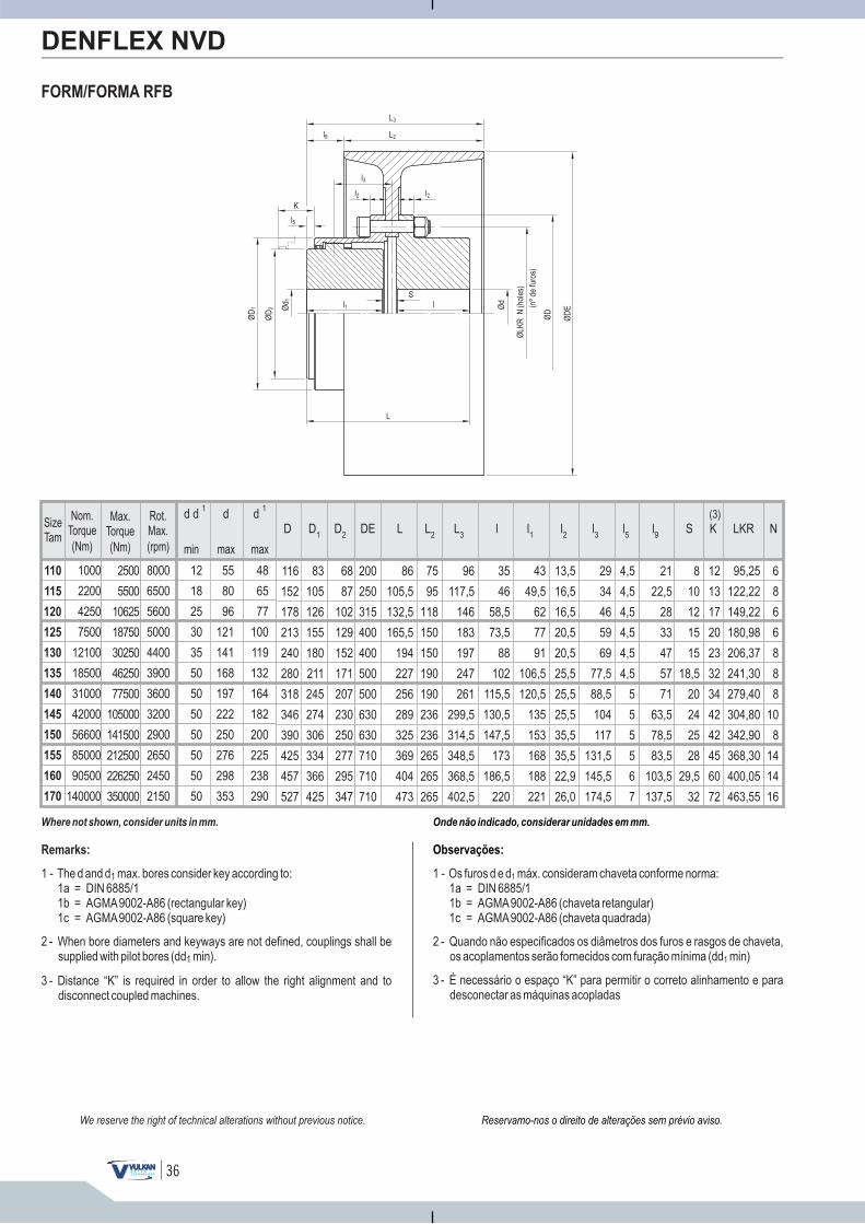
110
115
120
125
130
135
140
145
150
155
160
170
12
18
25
30
35
50
50
50
50
50
50
50
1000
2200
4250
7500
12100
18500
31000
42000
56600
85000
90500
140000
8000
6500
5600
5000
4400
3900
3600
3200
2900
2650
2450
2150
2500
5500
10625
18750
30250
46250
77500
105000
141500
212500
226250
350000
55
80
96
121
141
168
197
222
250
276
298
353
d d 1 d 1d
48
65
77
100
119
132
164
182
200
225
238
290
36
Onde não indicado, considerar unidades em mm.
Observações:
1 - Os furos d e d máx. consideram chaveta conforme norma:1a = DIN 6885/11b = AGMA9002-A86 (chaveta retangular)1c = AGMA9002-A86 (chaveta quadrada)
1
2 - Quando não especificados os diâmetros dos furos e rasgos de chaveta,os acoplamentos serão fornecidos com furação mínima (dd min)1
3 - É necessário o espaço “K” para permitir o correto alinhamento e paradesconectar as máquinas acopladas
FORM/FORMA RFB
DENFLEX NVD
Ød 1
K
l1S
l
L
Ød
ØLK
RN
(nºd
e)
furo
s
(hol
es)
ØD
L2
ØD
E
L3
ØD
2
ØD
1
l5
l3
l2
l9
l2
Reservamo-nos o direito de alterações sem prévio aviso.We reserve the right of technical alterations without previous notice.
Where not shown, consider units in mm.
Remarks:
1 - The d and d max. bores :1a = DIN 6885/11b = AGMA9002-A86 (rectangular key)1c = AGMA9002-A86 (square key)
1 consider key according to
2 - When bore diameters and keyways are not defined, couplings shall besupplied with pilot bores (dd min).1
3 - Distance “K” is required in order to allow the right alignment and todisconnect coupled machines.
l9
l1
l2
l3
Nl5
S LKRK(3)
lD2
DED1
D L L2
L3
43
49,5
62
77
91
106,5
120,5
135
153
168
188
221
6
8
6
6
8
8
8
10
8
14
14
16
4,5
4,5
4,5
4,5
4,5
4,5
5
5
5
5
6
7
95,25
122,22
149,22
180,98
206,37
241,30
279,40
304,80
342,90
368,30
400,05
463,55
12
13
17
20
23
32
34
42
42
45
60
72
35
46
58,5
73,5
88
102
115,5
130,5
147,5
173
186,5
220
83
105
126
155
180
211
245
274
306
334
366
425
68
87
102
129
152
171
207
230
250
277
295
347
116
152
178
213
240
280
318
346
390
425
457
527
86
105,5
132,5
165,5
194
227
256
289
325
369
404
473
75
95
118
150
150
190
190
236
236
265
265
265
200
250
315
400
400
500
500
630
630
710
710
710
96
117,5
146
183
197
247
261
299,5
314,5
348,5
368,5
402,5
13,5
16,5
16,5
20,5
20,5
25,5
25,5
25,5
35,5
35,5
22,9
26,0
29
34
46
59
69
77,5
88,5
104
117
131,5
145,5
174,5
21
22,5
28
33
47
57
71
63,5
78,5
83,5
103,5
137,5
8
10
12
15
15
18,5
20
24
25
28
29,5
32
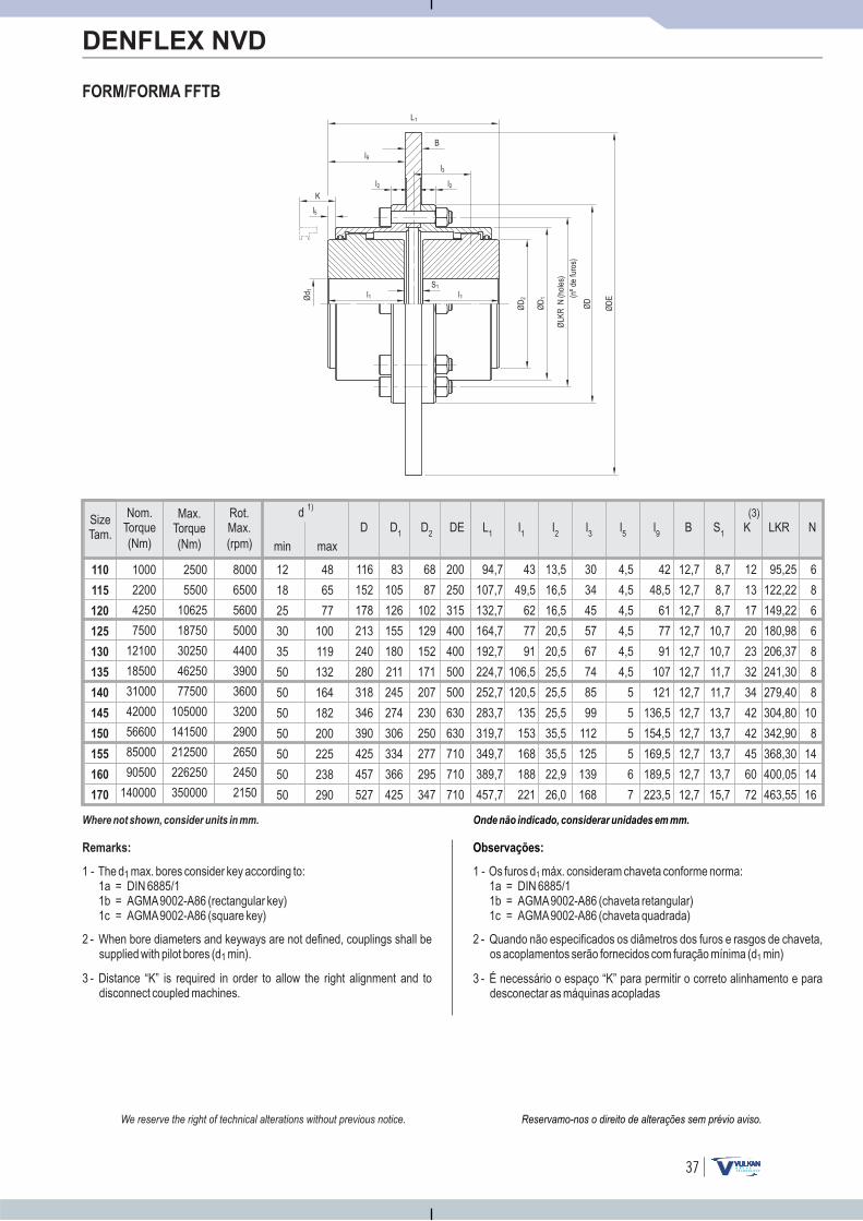
SizeTam.
min max
d 1)
(Nm)
Max.Torque
(Nm)
Nom.Torque
(rpm)
Rot.Max.
48
65
77
100
119
132
164
182
200
225
238
290
12
18
25
30
35
50
50
50
50
50
50
50
110
115
120
125
130
135
140
145
150
155
160
170
1000
2200
4250
7500
12100
18500
31000
42000
56600
85000
90500
140000
2500
5500
10625
18750
30250
46250
77500
105000
141500
212500
226250
350000
8000
6500
5600
5000
4400
3900
3600
3200
2900
2650
2450
2150
37
Onde não indicado, considerar unidades em mm.
Observações:
1 - Os furos d máx. consideram chaveta conforme norma:1a = DIN 6885/11b = AGMA9002-A86 (chaveta retangular)1c = AGMA9002-A86 (chaveta quadrada)
1
2 - Quando não especificados os diâmetros dos furos e rasgos de chaveta,os acoplamentos serão fornecidos com furação mínima (d min)1
3 - É necessário o espaço “K” para permitir o correto alinhamento e paradesconectar as máquinas acopladas
FORM/FORMA FFTB
DENFLEX NVD
Ød 1
K
l1S1
l1
ØD
2
ØLK
RN
(nºd
e)
furo
s
(hol
es)
ØD
1
ØD
ØD
E
L1
B
l5
l3
l2
l9
l2
Reservamo-nos o direito de alterações sem prévio aviso.We reserve the right of technical alterations without previous notice.
Where not shown, consider units in mm.
Remarks:
1 - The d max. bores :1a = DIN 6885/11b = AGMA9002-A86 (rectangular key)1c = AGMA9002-A86 (square key)
1 consider key according to
2 - When bore diameters and keyways are not defined, couplings shall besupplied with pilot bores (d min).1
3 - Distance “K” is required in order to allow the right alignment and todisconnect coupled machines.
95,25
122,22
149,22
180,98
206,37
241,30
279,40
304,80
342,90
368,30
400,05
463,55
43
49,5
62
77
91
106,5
120,5
135
153
168
188
221
13,5
16,5
16,5
20,5
20,5
25,5
25,5
25,5
35,5
35,5
22,9
26,0
30
34
45
57
67
74
85
99
112
125
139
168
4,5
4,5
4,5
4,5
4,5
4,5
5
5
5
5
6
7
42
48,5
61
77
91
107
121
136,5
154,5
169,5
189,5
223,5
12,7
12,7
12,7
12,7
12,7
12,7
12,7
12,7
12,7
12,7
12,7
12,7
8,7
8,7
8,7
10,7
10,7
11,7
11,7
13,7
13,7
13,7
13,7
15,7
12
13
17
20
23
32
34
42
42
45
60
72
116
152
178
213
240
280
318
346
390
425
457
527
83
105
126
155
180
211
245
274
306
334
366
425
68
87
102
129
152
171
207
230
250
277
295
347
200
250
315
400
400
500
500
630
630
710
710
710
6
8
6
6
8
8
8
10
8
14
14
16
L1LKRl
1l2
l3
l5
l9
B S1
K(3)
D D2
DED1
N
94,7
107,7
132,7
164,7
192,7
224,7
252,7
283,7
319,7
349,7
389,7
457,7
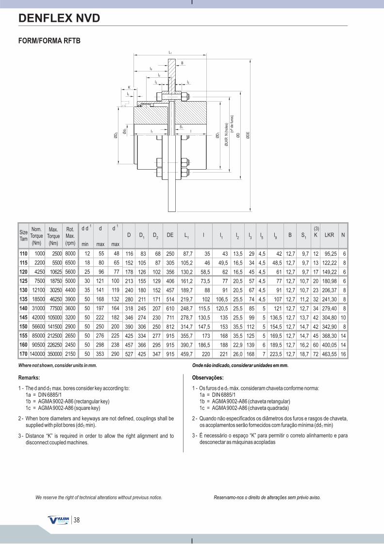
110
115
120
125
130
135
140
145
150
155
160
170
12
18
25
30
35
50
50
50
50
50
50
50
1000
2200
4250
7500
12100
18500
31000
42000
56600
85000
90500
140000
8000
6500
5600
5000
4400
3900
3600
3200
2900
2650
2450
2150
2500
5500
10625
18750
30250
46250
77500
105000
141500
212500
226250
350000
55
80
96
121
141
168
197
222
250
276
298
353
d d 1 d 1d
48
65
77
100
119
132
164
182
200
225
238
290
38
Onde não indicado, considerar unidades em mm.
Observações:
1 - Os furos d e d máx. consideram chaveta conforme norma:1a = DIN 6885/11b = AGMA9002-A86 (chaveta retangular)1c = AGMA9002-A86 (chaveta quadrada)
1
2 - Quando não especificados os diâmetros dos furos e rasgos de chaveta,os acoplamentos serão fornecidos com furação mínima (dd min)1
3 - É necessário o espaço “K” para permitir o correto alinhamento e paradesconectar as máquinas acopladas
FORM/FORMA RFTB
DENFLEX NVD
42
48,5
61
77
91
107
121
136,5
154,5
169,5
189,5
223,5
12,7
12,7
12,7
12,7
12,7
12,7
12,7
12,7
12,7
12,7
12,7
12,7
43
49,5
62
77
91
106,5
120,5
135
153
168
188
221
6
8
6
6
8
8
8
10
8
14
14
16
13,5
16,5
16,5
20,5
20,5
25,5
25,5
25,5
35,5
35,5
22,9
26,0
4,5
4,5
4,5
4,5
4,5
4,5
5
5
5
5
6
7
9,7
9,7
9,7
10,7
10,7
11,2
12,7
13,7
14,7
14,7
16,2
18,7
95,25
122,22
149,22
180,98
206,37
241,30
279,40
304,80
342,90
368,30
400,05
463,55
12
13
17
20
23
32
34
42
42
45
60
72
35
46
58,5
73,5
88
102
115,5
130,5
147,5
173
186,5
220
83
105
126
155
180
211
245
274
306
334
366
425
68
87
102
129
152
171
207
230
250
277
295
347
116
152
178
213
240
280
318
346
390
425
457
527
250
305
356
406
457
514
610
711
812
915
915
915
87,7
105,2
130,2
161,2
189,7
219,7
248,7
278,7
314,7
355,7
390,7
459,7
l9 Bl1
Nl2
l3
l5
LKRK(3)
lD2
D1
D L1
DE S1
29
34
45
57
67
74
85
99
112
125
139
168
Ød 1
K
l1S1
l
ØD
2
ØLK
RN
(nºd
e)
furo
s
(hol
es)
ØD
1
ØD
ØD
E
L1
B
l5
l3
l2
l9
l2
Reservamo-nos o direito de alterações sem prévio aviso.We reserve the right of technical alterations without previous notice.
Where not shown, consider units in mm.
Remarks:
1 - The d and d max. bores :1a = DIN 6885/11b = AGMA9002-A86 (rectangular key)1c = AGMA9002-A86 (square key)
1 consider key according to
2 - When bore diameters and keyways are not defined, couplings shall besupplied with pilot bores (dd min).1
3 - Distance “K” is required in order to allow the right alignment and todisconnect coupled machines.

SizeTam.
min max
d 1)
(Nm)
Max.Torque
(Nm)
Nom.Torque
(rpm)
Rot.Max.
48
65
77
100
119
132
164
182
200
225
238
290
12
18
25
30
35
50
50
50
50
50
50
50
110
115
120
125
130
135
140
145
150
155
160
170
1000
2200
4250
7500
12100
18500
31000
42000
56600
85000
90500
140000
2500
5500
10625
18750
30250
46250
77500
105000
141500
212500
226250
350000
8000
6500
5600
5000
4400
3900
3600
3200
2900
2650
2450
2150
39
Onde não indicado, considerar unidades em mm.
Observações:
FORM/FORMA FFAR
DENFLEX NVD
1 - Os furos d e d máx. consideram chaveta conforme norma:1a = DIN 6885/11b = AGMA9002-A86 (chaveta retangular)1c = AGMA9002-A86 (chaveta quadrada)
1
2 - Quando não especificados os diâmetros dos furos e rasgos de chaveta,os acoplamentos serão fornecidos com furação mínima (dd min)1
3 - É necessário o espaço “K” para permitir o correto alinhamento e paradesconectar as máquinas acopladas
Engagement /Disengagement hand lever (optional)
Palanca de enganche /desengate manual (opcional)
Ød 1 l
S1
l1
ØD
2
ØD
4
L1
ØLK
RN
(nºd
e)
furo
s
(hol
es)
ØD
3
ØD
1
ØD
Ød
l3
l2 l2
l4
Reservamo-nos o direito de alterações sem prévio aviso.We reserve the right of technical alterations without previous notice.
Where not shown, consider units in mm.
Remarks:
1 - The d and d max. bores :1a = DIN 6885/11b = AGMA9002-A86 (rectangular key)1c = AGMA9002-A86 (square key)
1 consider key according to
2 - When bore diameters and keyways are not defined, couplings shall besupplied with pilot bores (dd min).1
3 - Distance “K” is required in order to allow the right alignment and todisconnect coupled machines.
3
3
3
5
5
6
6
8
8
8
8
10
12
13
17
20
23
32
34
42
42
45
60
72
95,25
122,22
149,22
180,98
206,37
241,30
279,40
304,80
342,90
368,30
400,05
463,55
6
8
6
6
8
8
8
10
8
14
14
16
13
14
22
22
26
29
36
40
44,5
54
54
63
116
152
178
213
240
280
318
346
390
425
457
527
83
105
126
155
180
211
245
274
306
334
366
425
68
87
102
129
152
171
207
230
250
277
295
347
159
184
197
229
247
302
353
394
381
451
476
584
128
147
179
214
246
276
306
314
360
386
465
479
72,5
82
104
127
133
158
177
174
199,5
199,5
166
263
43
52
62
73
99
102
112
122
143
168
181
197
16
19
19
23
23
28
28
28
38
38
25,4
28,5
93
108
136
165
200
219
245
252
283
338
370
383
S1K LKR Nl
4D D
2D
4D
1L
1l1
l l2
l3
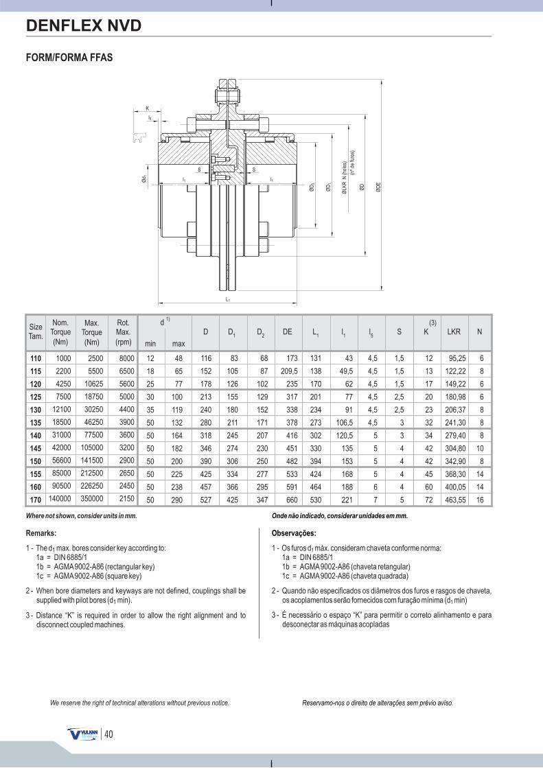
SizeTam.
min max
d 1)
(Nm)
Max.Torque
(Nm)
Nom.Torque
(rpm)
Rot.Max.
48
65
77
100
119
132
164
182
200
225
238
290
12
18
25
30
35
50
50
50
50
50
50
50
110
115
120
125
130
135
140
145
150
155
160
170
1000
2200
4250
7500
12100
18500
31000
42000
56600
85000
90500
140000
2500
5500
10625
18750
30250
46250
77500
105000
141500
212500
226250
350000
8000
6500
5600
5000
4400
3900
3600
3200
2900
2650
2450
2150
40
FORM/FORMA FFAS
DENFLEX NVD
Onde não indicado, considerar unidades em mm.
Observações:
1 - Os furos d máx. consideram chaveta conforme norma:1a = DIN 6885/11b = AGMA9002-A86 (chaveta retangular)1c = AGMA9002-A86 (chaveta quadrada)
1
2 - Quando não especificados os diâmetros dos furos e rasgos de chaveta,os acoplamentos serão fornecidos com furação mínima (d min)1
3 - É necessário o espaço “K” para permitir o correto alinhamento e paradesconectar as máquinas acopladas
Ød 1
K
l1
S
l1
L1
ØD
2
ØLK
RN
(nºd
e)
furo
s
(hol
es)
ØD
1
ØD
S
ØD
E
l5
Reservamo-nos o direito de alterações sem prévio aviso.We reserve the right of technical alterations without previous notice.
Where not shown, consider units in mm.
Remarks:
1 - The d max. bores :1a = DIN 6885/11b = AGMA9002-A86 (rectangular key)1c = AGMA9002-A86 (square key)
1 consider key according to
2 - When bore diameters and keyways are not defined, couplings shall besupplied with pilot bores (d min).1
3 - Distance “K” is required in order to allow the right alignment and todisconnect coupled machines.
12
13
17
20
23
32
34
42
42
45
60
72
1,5
1,5
1,5
2,5
2,5
3
3
4
4
4
4
5
4,5
4,5
4,5
4,5
4,5
4,5
5
5
5
5
6
7
83
105
126
155
180
211
245
274
306
334
366
425
68
87
102
129
152
171
207
230
250
277
295
347
173
209,5
235
317
338
378
416
451
482
533
591
660
116
152
178
213
240
280
318
346
390
425
457
527
43
49,5
62
77
91
106,5
120,5
135
153
168
188
221
131
138
170
201
234
273
302
330
394
424
464
530
95,25
122,22
149,22
180,98
206,37
241,30
279,40
304,80
342,90
368,30
400,05
463,55
K(3)
Sl5
D D2
DED1
l1
L1
LKR N
6
8
6
6
8
8
8
10
8
14
14
16

41
DRI (1)
(mm)
DMA (2)
(mm)
S1 (3)
(mm) (mm) (mm)(mm)
Radial R� Axial
3,0
3,0
3,0
5,0
5,0
6,0
6,0
8,0
8,0
8,0
8,0
10,0
10,0
13,0
12,0
14,0
14,0
± 0,5
± 0,5
± 0,5
± 0,6
± 0,6
± 0,7
± 0,7
± 0,8
± 0,8
± 0,8
± 0,8
± 1,0
± 1,0
± 1,0
± 1,0
± 1,0
± 1,0
4,0
4,0
4,0
5,0
5,0
5,5 5
7,0
8,0
9,0 9
9,0 9
10,5 1 0
13,0
13,0
15,0
16,0
17,0
17,0
± 0,5
± 0,5
± 0,5
± 0,5
± 0,5
± 0,
± 0,7
± 0,8
± 0,
± 0,
± ,
± 1,0
± 1,0
± 1,0
± 1,0
± 1,0
± 1,0
0,57
0,81
1,10
1,41
1,67
1,86
2,15
2,51
2,85
3,19
3,59
4,32
4,79
5,22
5,75
6,45
6,67
0,05
0,07
0,10
0,10
0,15
0,15
0,20
0,20
0,25
0,25
0,30
0,35
0,40
0,40
0,45
0,50
0,55
DRI (1) DMA (2) S (3)
Angular A� Axial
0,77
1,14
1,33
1,69
1,99
2,24
2,71
3,01
3,27
3,62
3,86
4,54
4,81
5,35
6,05
6,70
7,35
0,06
0,10
0,10
0,15
0,15
0,20
0,20
0,25
0,25
0,30
0,30
0,40
0,40
0,45
0,50
0,55
0,60
DRI (1) DMA (2)
Angular A�
Form/Forma FF (4) Form/Forma RF (4)
1,54
2,28
2,67
3,38
3,98
4,48
5,42
6,02
6,54
7,25
7,72
9,08
9,63
10,70
12,10
13,40
14,70
0,10
0,20
0,20
0,30
0,35
0,35
0,45
0,50
0,55
0,60
0,65
0,75
0,80
0,90
1,00
1,10
1,20
DENFLEX NVD
MISALIGNMENT LIMITS LIMITES DE DESALINHAMENTO
A curvatura do perfil dos dentes externos do cubo combinados comos dentes internos da capa criam uma articulação, permitindo obasculamento angular de até 0,75º em qualquer direção, sendoválido para todos os tamanhos da linha NVD. Esta característicaenquadra os acoplamentos de engrenagem NVD na categoria de“acoplamento flexível torcionalmente rígido”.
Size
Tam.
110
115
120
125
130
135
140
145
150
155
160
170
180
190
200
210
220
S1
RADIAL/AXIAL
�R
A2
S1
A1
A2
S
A1
ANGULAR
ANGULAR
Form/Forma RFForm/Forma FF
�A = A - A2 1 �A = A - A2 1
MISALIGNMENT LIMITS / LIMITES DE DESALINHAMENTOS
(mm) (mm)
Acombinação de duas articulações na forma construtiva FF, permitea compensação de desalinhamentos radiais e angulares entre oseixos acoplados. Já os acoplamentos da forma RF, dotados de umaúnica articulação, não permitem a compensação dedesalinhamento radial.
The curved profile of the hub external gear teeth, together with thesleeve internal gear teeth, creates a link, a maximum of0.75º angular tilting, in any direction, and it is valid for every NVDsizes. This feature includes NVD Gear Couplings in the class of“Rigid Torsionally Flexible Coupling”.
allowing
Two-link combination, as in the FF construction form, allows radialand angular misalignments between coupled shafts. However, RFform couplings, containing only one link, radialmisalignment.
does not allow
Reservamo-nos o direito de alterações sem prévio aviso.We reserve the right of technical alterations without previous notice.

42
DENFLEX NVD
1) DRI - Desalinhamentos máximos recomendados na
instalação (montagem)
A vida útil do acoplamento e o bom rendimento da transmissãodependem do perfeito alinhamento entre os eixos das máquinasacopladas. Quanto maior o desalinhamento, maior será o desgastedo acoplamento. Recomenda-se que os desalinhamentos residuaisda montagem sejam o mínimo possível. Na tabela são indicados osvalores referenciais (DRI) para o controle do alinhamento após amontagem dos acoplamentos.
2) DMA - Desalinhamentos máximos absolutos
(operação)
Os valores tabelados de DMA angular (DA) e radial (DR), produzemcada qual, isoladamente, a flexão máxima de 0,75º nas articulaçõesdo acoplamento (entre cubo e capa).Para que esse limite não seja ultrapassado, obrigatoriamente énecessário restringir o efeito combinado de ambos DMA´s, de talforma que o percentual disponível de um tipo de desalinhamentocorresponda ao percentual não utilizado do outro.Exemplo: Se utilizado 40% do DMA angular, restará disponível 60%do DMAradial e vice-versa.O DMA deve ser entendido como uma reserva de capacidade doacoplamento para a compensação de desalinhamentos de difícilprevisibilidade, tais como, os provocados pelas cargas de trabalhonas máquinas acopladas, dilatações térmicas, vibrações,acomodação das fundações, etc.Assim sendo, o DMAnão deve serutilizado como referência de controle do alinhamento quando damontagem.
RADIAL
L
ØD
2
4.2) DRI:12
DMA
3) A dimensão S ou S1, representa o espaço entre os cubos e é oparâmetro de controle do posicionamento axial dos mesmos.
4) Os valores tabelados consideram as formas construtivas FF, FLFe RF padrões, conforme catálogo. Para outras formasconstrutivas não abrangidas pela tabela (formas FEF, RFFR,FRRF, etc.), os desalinhamentos admissíveis poderão serestimados como se segue:
Obs: Em caso de divergência entre as informações do desenhotécnico de fornecimento e este catálogo, prevalecem as dodesenho.
4.1) DMA: for/para �A38,2ØD2 for/para �R
76,4L
1) DRI - Maximum misalignments recommended for
installation (assembling)
The coupling's useful life and a good transmission performancedepend on the perfect alignment between the coupled machinesshafts. The greater is misalignment, the greater coupling wearshould be. It is advisable that residual assembling misalignmentsare restricted to the minimum as possible. On the table, referencevalues (DRI) for alignment control after coupling assembling arehighlighted.
2) DMA - Absolute maximum misal ignments
(operation)
Angular DMA (DA) and radial DMA (DR) tabled values generateeach one, individually, a maximum 0.75º angular tilting on couplinglinks (between the hub and sleeve).In order for such maximum value not be exceeded, it must berequired to limit both DMA combined effects, in a way that thepercentage of one type of misalignment corresponds to thepercentage not used by the other.Example: If a 40% angular DMA is used, a 60% radial DMA willremain available, and vice-versa.DMAshall be understood as coupling reserved capacity for a difficultforecast on misalignments compensation, such as those caused bycoupled machines workloads, thermal expansion, vibration,foundation adjustment, etc. So, DMAshall not be used as alignmentcontrol reference of assembling.
3) Dimension S or S is a gap between the cubes, and it is a controlparameter for their axial positioning.
1
4) Tabled values consider standard FF, FLF and RF constructionforms, as in catalog. For other construction forms not included inthe table (FEF, RFFR, FRRF forms, etc.), allowablemisalignments may be forecast as follows:
Reservamo-nos o direito de alterações sem prévio aviso.We reserve the right of technical alterations without previous notice.
Remark: If there is a difference between supplying technicaldrawing information and this catalog, drawinginformation shall prevail.
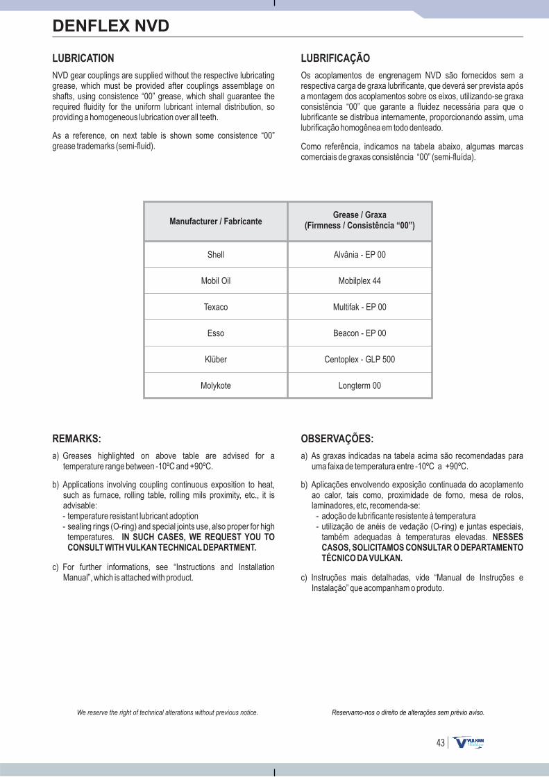
43
DENFLEX NVD
LUBRICATION LUBRIFICAÇÃO
Os acoplamentos de engrenagem NVD são fornecidos sem arespectiva carga de graxa lubrificante, que deverá ser prevista apósa montagem dos acoplamentos sobre os eixos, utilizando-se graxaconsistência “00” que garante a fluidez necessária para que olubrificante se distribua internamente, proporcionando assim, umalubrificação homogênea em todo denteado.
Manufacturer / Fabricante
Shell
Mobil Oil
Texaco
Esso
Klüber
Molykote
Alvânia - EP 00
Mobilplex 44
Multifak - EP 00
Beacon - EP 00
Centoplex - GLP 500
Longterm 00
Como referência, indicamos na tabela abaixo, algumas marcascomerciais de graxas consistência “00” (semi-fluída).
REMARKS: OBSERVAÇÕES:
a) As graxas indicadas na tabela acima são recomendadas parauma faixa de temperatura entre -10ºC a +90ºC.
b) Aplicações envolvendo exposição continuada do acoplamentoao calor, tais como, proximidade de forno, mesa de rolos,laminadores, etc, recomenda-se:
- adoção de lubrificante resistente à temperatura- utilização de anéis de vedação (O-ring) e juntas especiais,
também adequadas à temperaturas elevadas. NESSES
CASOS, SOLICITAMOS CONSULTAR O DEPARTAMENTO
TÉCNICO DAVULKAN.
c) Instruções mais detalhadas, vide “Manual de Instruções eInstalação” que acompanham o produto.
NVD gear couplings are supplied without the respective lubricatinggrease, which must be provided after couplings assemblage onshafts, using consistence “00” grease, which shall guarantee therequired fluidity for the uniform lubricant internal distribution, soproviding a homogeneous lubrication over all teeth.
As a reference, on next table is shown some consistence “00”grease trademarks (semi-fluid).
a) Greases highlighted on above table are advised for atemperature range between -10ºC and +90ºC.
b) Applications involving coupling continuous exposition to heat,such as furnace, rolling table, rolling mils proximity, etc., it isadvisable:- temperature resistant lubricant adoption- sealing rings (O-ring) and special joints use, also proper for high
temperatures. IN SUCH CASES, WE REQUEST YOU TO
CONSULT WITH VULKAN TECHNICAL DEPARTMENT.
c) For further informations, see “Instructions and InstallationManual”, which is attached with product.
Reservamo-nos o direito de alterações sem prévio aviso.We reserve the right of technical alterations without previous notice.
Grease
Firmness
/ Graxa
( / Consistência “00”)
DENFLEX NVD
Notes / Anotações:
44
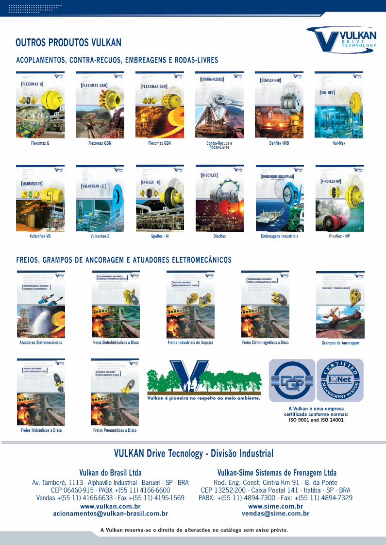
OUTROS PRODUTOS VULKAN
VULKAN Drive Tecnology - Divisão Industrial
Vulkan do Brasil Ltda Vulkan-Sime Sistemas de Frenagem Ltda
A Vulkan reserva-se o direito de alteracões no catálogo sem aviso prévio.
ACOPLAMENTOS, CONTRA-RECUOS, EMBREAGENS E RODAS-LIVRES
FREIOS, GRAMPOS DE ANCORAGEM E ATUADORES ELETROMECÂNICOS
Atuadores Eletromecânicos Freios Eletrohidráulicos a Disco Freios Industriais de Sapatas Freios Eletromagnéticos a Disco Grampos de Ancoragem
Freios Hidráulicos a Disco Freios Pneumáticos a Disco
A Vulkan é uma empresacertificada conforme normas:
ISO 9001 and ISO 14001
Av. Tamboré, 1113 - Alphaville Industrial - Barueri - SP - BRACEP 06460-915 - PABX +(55 11) 4166-6600
Vendas +(55 11) 4166-6633 - Fax +(55 11) 4195-1569www.vulkan.com.br
Rod. Eng. Const. Cintra Km 91 - B. da Ponte CEP 13252-200 - Caixa Postal 141 - Itatiba - SP - BRA
PABX: +(55 11) 4894-7300 - Fax: +(55 11) 4894-7329www.sime.com.br
Flexomax G Flexomax GBN Flexomax GSN Contra-Recuos eRodas-Livres
Vulbraflex VB Speflex - NVulkardan-E Discflex Embreagens Industriais Pinoflex - NP
Denflex NVD Vul-Mex