CONTINUOUS WEIGHING & FEEDING OF BULK MATERIALS · automatically applying a known test load and...
5
LOSS-IN-WEIGHT FEEDERS SCREW VIBRATORY VANE CONTINUOUS BATCH THAYER SCALE CONTINUOUS WEIGHING & FEEDING OF BULK MATERIALS
Transcript of CONTINUOUS WEIGHING & FEEDING OF BULK MATERIALS · automatically applying a known test load and...

LOSS-IN-WEIGHT FEEDERS
SCREWVIBRATORYVANECONTINUOUS BATCH
THAYER SCALECONTINUOUS WEIGHING & FEEDING OF BULK MATERIALS

Thayer Scale Loss-In-Weight Feeders are designed to provide precision class accuracy and repeatability even in the harshest of industrial environments. They range in capacity from grams per minute to tons per hour.
These are the most versatile feeders in the industry. At the heart of each Loss-In-Weight Feeder is a THAYER scale that has been designed exclusively for the stringent requirements of Loss-In-Weight feeding.
Thayer Scale offers a powerful set of proprietary add-on accessories that are designed to defeat the problematic flow issues encountered by industry such as bridging, flushing, adhesion and cohesion. Comprehensive process solutions that can only come from a company with over fifty years experience.
“FMSS” CABLE SUSPENSION SYSTEMThe THAYER Cable Suspension System (patented) is the most rugged and forgiving Force Measurement Weighing System available on today’s market. It can take more physical abuse and can tolerate more foundation distortion/deflection than all other known designs.
The exclusive Thayer Scale “FMSS” (Force Measurement Suspension System) design provides extremely high sensitivity. Feeder and weigh hopper “dead load” are mass-counterbalanced so that only material weight (live load) is measured. This feature helps assure excellent control in “noisy” environments.
All of the articulate parts of the scale mechanism are supported from “axially inextensible, but laterally yieldable” suspension elements (stainless steel pre-stressed aircraft cable), which are arranged to hang freely, thereby avoiding any appreciable spring or hysteresis effect, variation in mechanical advantage, or binding due to imperfect leveling.
Because of this unique mechanical property of the force transmission system, any laterally directed forces and shock on the scale or its supported feeder can not cause destructive shear and bending stresses to develop in the elements themselves or at the load cell junction. The system, being yieldable in the lateral direction, is therefore effectively and completely protected by using laterally placed “stops” in proximity of the weighed structure.
AUTOMATED TEST WEIGHT LIFTER (ATWL) for Cable ScaleMore and more weigh feeders are being used in conjunction with statistical process control where performance records are routinely generated and delivered with the product as required by a customer’s quality assurance program. Such a record should contain a “validation of scale calibration” step to be truly meaningful as a quality assurance tool. Thayer Scale’s Automated Test Weight Lifter (“ATWL”) provides a means for automatically applying a known test load and going through a calibration sequence on computer or push-button command to check scale calibration. A “foolproof” self-checking software algorithm in the feeder control instrumentation prevents erroneous calibration.
The test weight calibration method has proven accurate and reliable over decades of in-plant use. Unlike material sampling, it is always clean, fast and safe and free from human error. Unlike electronic signal simulation, it mechanically tests the performance of critical electro-mechanical components under the full deflection range of the load cell.
• Accurately measures load regardless of load position.• Immune to support structure deflections and process
vibrations.• Inherently self aligning to gravity.• Nulls out heavy tare loads.• 1,000% over load capacity.• Scale may be suspended from above or supported below.• Immune to shock or impact loads. • Easily accessible load cell can be accessed without
removing the feeder.
Two Types Load Cells to Choose From THAYER LVDT Load Cell The LVDT Load Cell was specifically developed as the ideal adjunct to THAYER’S “reverse-action” Force Measurement Suspension System. It is essentially a precision and extremely durable “tension-style” force transducer that is manufactured in a fine series of force ranges to produce scale capacities from 10 to 500 lbs depending on the application. The LVDT is the ideal load cell for “light loading” applications where mechanical tare loads represent as much as 10 to 40 times the net material load and provides unparalleled overload protection at 1000% of rated output.
THAYER Strain Gauge Load Cell The Strain Gauge Load Cell is available in force ranges from 25 to 500 lbs with an overload protection of 300% of rated output.
“FMSS” FLEXURE PLATE SYSTEM Flexure plate system eliminates all wearing parts, such as bearings, pivots and knife edges and is not susceptible to vibration. Flexure suspension system transfers all loading forces to a single load transducer, which accurately measures load regardless of load position. Most platform scales are not designed to be immune to side loading and/or tortional loading caused by the plant environment and by the movement of the feed screw, agitator, etc. These factors can cause poor accuracy and poor calibration stability. Thayer’s flexure system cancels all horizontal force vectors and also allows heavy tare loads (weight of feeder and hopper) to be completely mass counterbalanced , permitting load cell sizing based on net rather than gross weight.
TWO TYPES OF SCALES TO CHOOSE FROM:
THAYER MODEL NO.
APPROX. FEED RATE
RANGE
SCALE CAPACITY (POUNDS)
WEIGH HOPPER EXTENSION CAPACITY
AVAILABLE SCREWS SCALE
SUSPENSION TYPE
LOAD CELL TYPE
ATWL CAPABLE TYPICAL MATERIALS HANDLED
MIN. MAX. MIN. MAX. LIQUID USABLE DIA. (IN)
MSF-15L-S 0.25 60 3 25 3 2.4
0.375 0.5
0.625 1.0
FLEXURE SGLVDT NO
CANDLE WAX, RICE POWDER, SALT, FLOUR, LITHIUM
ION POWDER, GROUND BIOMASS, VITAMIN ADDITIVE,
SEASONING
PFM-15L-S 20 1,250 10 200
1.03.0
5.527.5
9.75
0.82.4
4.426.07.8
1.0 1.5 2.0
FLEXURE SGLVDT NO
GRAPHITE POWDER, ZINC OX-IDE, KAOLIN CLAY, GUAR GUM,
PLASTIC ADDITIVE, QUICK LIME, PIGMENT, COPPER POW-DER, RUBBER GRANULES, TSP,
WHEY POWDER
PFM-18L-S 20 1,250 10 500
1.03.0
5.527.5
9.75
0.82.4
4.426.07.8
1.0 1.5 2.0
FLEXURE SGLVDT NO
TRONA ORE, MICROCELL E, POWDERED MILK ADDITIVE, CALCIUM CARBONATE, SALT, SPICE, ADDITIVE POWDERS,
TiO2, STEARATE, BORAX
PF-18L-S 20 7,500 10 500
1.03.0
5.527.5
9.75
0.82.4
4.426.07.8
1.0 1.5 2.0 3.0 4.0 6.0
FLEXURE SGLVDT NO
COCOA POWDER, FLOUR, RICE, IMPACT MODIFIER, PP PELLETS, CRUMB RUBBER,
SUGAR, ADVAWAX, CALCIUM STEARATE, ALMONDS, TOFFEE
CHIPS
MSF-MC-S 0.50 900 5 2501.03.0
1.83.65.47.2
0.375 0.5
0.625 1.0
CABLE SGLVDT YES
SPICES, SEASONING ADDITIVE, CANDLE WAX
BEADS, CALCIUM CARBONATE, VITAMIN POWDER, GRAPHITE
POWDER
PFM-SC-S 20 1,250 30 500
1.23.0
5.257.5
9.75
0.962.4
1.0 1.5 2.0
CABLE SGLVDT YES
CLAY, POLYETHYLENE PEL-LETS, LIMESTONE, PIGMENTS,
IRON OXIDE, ZINC BORATE, ZINC OXIDE, OSB RESIN,
QUICK LIME, STARCH, FLUOR-SPAR, ZEOLITE
PF-SC-S 20 7.500 30 500
3.3754.5
6.759.0
10.011.2515.05.739.8311.8313.8315.83
2.73.65.47.28.09.0
12.04.587.869.4611.0612.66
1.0 1.5 2.0 3.0 4.0 6.0
CABLE SGLVDT YES
PULVERIZED LIMESTONE, AMMONIUM BICARBONATE, SODA ASH, EAF DUST, OAT FLAKES, PLASTIC RESIN,
TALC, RUBBER, MICA, VITAMIN POWDER, BRAN,
CALCIUM CARBONATE, ZINC OXIDE, PLASTIC STABILIZER,
PULVERIZED COAL
PF-LC-S 100 250 2,200
5.739.8311.8313.8315.8320.030.040.050.060.0
4.587.869.4611.0612.6616.024.032.040.048.0
3.0 4.0 6.0 CABLE SG
LVDT YES
PLASTIC PELLETS, AGRICULTURAL CHEMICALS, CEMENT, GYPSUM, SNACK
FOOD MIX, DOG FOOD PREMIX., COCOA POWDER
TiO2, CHROMATE ORE, SODA ASH, CALCIUM OXIDE, TALC
LOSS-IN-WEIGHT SCREW FEEDERS

Powder FeederTM “U-Trough” Problem: Conventional feeders cannot reliably meter difficult powdersIt is difficult to achieve reliable feeding of powders such as Cabosil®, TiO2 and other sticky and cohesive powders with conventional feeders. These powders create problems such as flooding, or bridging above the feed screw and thus interrupting flow. They can also bind the screw flights and thus damage the equipment and halt production.
Normal adjustable operating range is a 20:1 turndown capability from maximum feed rate. Special ranges are available.
Solution: Patented system that assures reliable meteringThe patented Thayer Scale “U-trough” hopper and feed section provides the first practical and economical means for metering difficult powders. The geometry of the trough and agitator effectively de-aerate and contain the powder on initial fill cycle to help prevent flooding. An independently driven agitator maintains optimum material conditioning while screw speed can vary to control flow rate. Material does not build up within the trough or feed tube, preventing binding or erratic feed. In conjunction with a THAYER® Loss of Weight scale system, the Powder Feeder U-trough provides the most reliable and accurate feed system for difficult powders
No Flood DesignStream of Material is deflected by the agitator bar, than curved sidewalls. Material velocity is reduced, controlling the tendency to aerate and flood.
FA - Flow of AgitatorFO - Flow of OverwindFS - Flow of Screw
Progressive opening of screw chamber and feed screw design work together to eliminate binding.
Trough agitator assures uniform material density and consistent filling of screw flights
THAYER MODEL No.
APPROX. FEED RATE RANGE
(lbs/hr)
SCALE CAPACITY (POUNDS)
HOPPER CAPACITY
(FT3)AVAILABLE TRAYS
SCALE SUSPENSION
TYPE
LOAD CELL
ATWL CAPABLE
TYPICAL MATERIALS HANDLED
MIN. MAX. MIN. MAX. MAX WIDTH (INCHES)
LENGTH (INCHES)
LWF-SG-10V 0.1 20 3 25 0.51.754.05.0
122020
FLEXURE SGLVDT NO
VITAMIN ADDITIVE, SEASONING, TALC POWDER, RESIN,
PIGMENTS, GRASS SEEDS, SALT
LWF-15L-V 10 750 10 200 3.0
4.05.0
2020 FLEXURE SG
LVDT NO
ZINC STEARATE, GRAPHITE POWDER, ZINC
OXIDE, KAOLIN CLAY, CORN STARCH, CARBON BLACK, POLYPROPYLENE
STRAND, PE POWDER, TOBACCO SEEDS
LWF-18L-V 10 3,000 10 500 6.04.05.0 7.0
202021
FLEXURE SGLVDT NO
ADDITIVE POWDERS, CITRATE ACID, POWDERED
METAL, FLOUR, TRISODIUM PHOSPHATE,
IRGONOX, POLYETHYLENE POWDER, RICE
LWF-MC-V 10 3,000 10 500 3.0 4.05.0
2020 FLEXURE SG
LVDT YES
CALCIUM STEARATE, ALMONDS, CEREAL, SAND,
PREMIX MASTERBATCH, CHOCOLATE CHUNKS, SCRAP FIBERGLASS, CHARCOAL, LLDPE
LWF-SC-V 10 4,000 30 500 204.05.0 7.0
202021
CABLE SGLVDT YES
SPICES, SEASONING, CALCIUM CARBONATE,
CRUMB RUBBER, SODIUM BICARBONATE, IRON POWDER, PE RESIN,
NYLON PELLETS
LWF-LC-V 100 7,000 250 2,500 751012
CUSTOMCUSTOM CABLE SG
LVDT YES
LIMESTONE, RESIN, PIGMENTS, FREEZE
DRIED STRAWBERRIES, FIBERGLASS, GRANULATED
GYPSUM,OXIDE PELLETS,
LWF-HC-V CONSULT FACTORY 400 4,000
CONSULT FACTORY CUSTOM
CUSTOM CUSTOM CABLE SGLVDT YES
GLASS CULLET, COKE BREEZE, ANTHRACITE
COAL, PULVERIZED LIMESTONE, SODA ASH, EAF DUST, OAT FLAKES, PLASTIC RESIN, TALC, RUBBER, PULVERIZED
COAL
LOSS-IN-WEIGHT VIBRATORY FEEDERS
THAYER SCALE Loss-In-Weight Vibratory Feeders Special Features and Benefits
Thayer Scale has spent many years developing the Loss-In-Weight Feeder and control system for use with vibratory feeders. Since virtually all of the controllers on the market were originally designed for use with a screw feeder, it should not be surprising to find that very few of them have the versatility to cope with the special requirements of the vibratory feeder type. Without (certain) special control features, the vibratory feeder can not be controlled effectively in a volumetric mode, nor can it be controlled gravimetrically over a wide operating range without making controller adjustments to suit its non-linear characteristics.
With complete absence of motors, bearings, seals and lubricating fluids, along with the un-contested pulse free delivery “smoothness” at maximum turn down, the vibratory feeder has powerful advantages over the screw feeder in a great number of applications.
Some important differences that need to be taken into account in controlling these two fundamentally different volumetric feed devices are:
1. The gain of a screw feeder is constant over its operating range. That is the increments of change in feed output for a given change in drive input is constant throughout its range. The “gain” of a vibratory feeder increases exponentially with its operating point. That is, the increment of change in feed output becomes larger for a given change in drive input as the operating point increases. The consequence of this is overall gain of the control loop is lower in the low operating ranges and higher in the high operating ranges. If something is not provided to compensate for this effect, the controller gain needs to be adjusted if the set point is changed any significant amount.
2. The “volumetric” delivery of a screw feeder stays relatively constant under a constant drive input (such as during hopper refill). Under conditions of a constant drive input, the “volumetric” delivery is relatively independent of material’s bulk density. Variation in its “gravimetric” delivery under constant drive input is essentially determined by density changes of the material handled at the time.3. The “volumetric” delivery of a vibratory feeder stays relatively constant providing the vibration amplitude is held consistent (frequency assumed constant @ 60 hz). However, for the vibration amplitude to hold constant, the drive input must be increased or decreased to offset the loading effect on the tray itself.
4. A screw feeder can accept a refill with less material “heel” (the minimum quantity of material that is always maintained over the feeder inlet) than a vibratory feeder can, since the flights of a screw within the feed tube offers greater resistance to “flushing’ than does an open channel tray.
5. The magnetic-drive of a vibratory feeder is capable of rapidly responding to changes in controller output signal. A gear-motor drive system for a screw feeder, and the screw itself, represents considerable angular ”inertia” which simply can not be made to respond quickly to demand changes.
SPIRALATORTM
Enjoy the benefits of using a simple and reliable vibratory feeder on non-floodable materials that normally can not be reliably discharged through the small opening of a conical hopper. The benefits of using a vibratory feeder in place of a screw feeder include: higher turn-down, pulsation-free discharge, cleaning ability, and elimination of troublesome seals and bearings.
The SPIRALATORTM is a slowly rotating, non-agitating, conical wire-spiral within the hopper which counteracts the material’s tendency to pack under its own weight by virtue of its “lifting” action throughout the stored material. The resulting reduction in consolidation pressures throughout the material mass assures that the stored material will not develop sufficient strength to form stable arches that can cause erratic flow or complete flow stoppage. The combination of the unique material conditioning system and a vibrating pan feeder assures that the material will be handled reliably and gently throughout the entire feeding range.
NODAL MEMBRANE VIBRATORY TRAY INSERTThis patented feeder meters material on an elastic membrane feed tray that responds uniquely to the action of the magnetic vibratory drive. A transverse multiple node standing wave is produced in the membrane that serves to discourage any ad-herence of material to its surface. The cross-sectional shape of the membrane is made up of multiple distinct curves which alternate between convexity and concavity so as to produce corresponding tensile and compressive surface strains in the elastomer. It is amplified and reversible surface “straining” (stretching and compressing) that creates the self- shedding action. The feeder is frequently supplied in combination with the SpiralatorTM agitator for sluggish powders.
Key Features of the THAYER Loss-In-Weight Controller That Addresses “Vibratory Feeder” Control Issues
1. “OCMP” (Controller Output Compensation). This is a vibratory feeder gain compensation control block that can be programmed into the control loop between the controller output stage and the drive input stage. It represents a “characteristic” equation that permits a single controller gain setup to operate over a wide range (typically 50:1 but can go as high as 100:1) with most vibratory feeders.
2. “EFT” Excitation Tracking. A transducer physically mounted to the vibratory tray is used in conjunction with specialized circuitry to control and monitor the amplitude of the vibratory tray. During gravimetric control cycles, amplitude readings and weight readings are combined in time adjustable averaging registers for purposes of continually updating a “density” register. Thus, when a volumetric feed cycle is called for during refill, the transducer signal and the density factor are combined to provide a dynamic weight-rate signal in the control loop in place of the normal scale-derived value. Thus “closed loop” control is never discontinued, and the feeder is always responsive to changing set points. Should head pressure on the vibrating tray begin to load down its amplitude, the controller automatically responds immediately with a compensatory output change.
This parameter, which has a direct effect on the system’s front-end damping, and thus its “measurement dead time”, establishes a limit on how high the controller gain can be set without experiencing bothersome control oscillation. The combination of less front-end damping along with the higher degree of responsiveness of a magnetic drive unit (over a motor drive), reduces the overall loop time-constant dramatically making the vibratory Loss-In-Weight Feeder an excellent choice where process demand changes may occur abruptly.
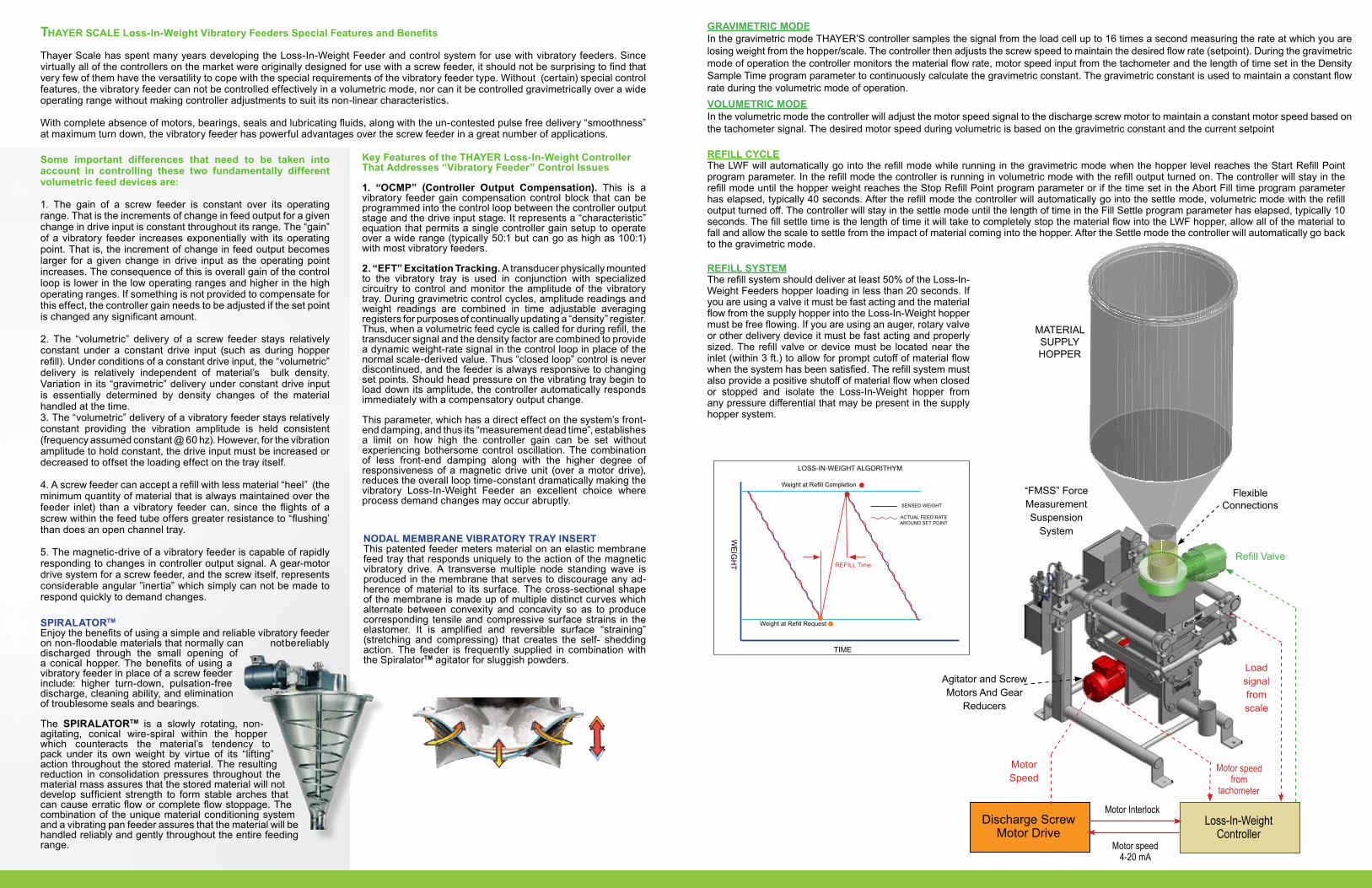
REFILL CYCLEThe LWF will automatically go into the refill mode while running in the gravimetric mode when the hopper level reaches the Start Refill Point program parameter. In the refill mode the controller is running in volumetric mode with the refill output turned on. The controller will stay in the refill mode until the hopper weight reaches the Stop Refill Point program parameter or if the time set in the Abort Fill time program parameter has elapsed, typically 40 seconds. After the refill mode the controller will automatically go into the settle mode, volumetric mode with the refill output turned off. The controller will stay in the settle mode until the length of time in the Fill Settle program parameter has elapsed, typically 10 seconds. The fill settle time is the length of time it will take to completely stop the material flow into the LWF hopper, allow all of the material to fall and allow the scale to settle from the impact of material coming into the hopper. After the Settle mode the controller will automatically go back to the gravimetric mode.
REFILL SYSTEMThe refill system should deliver at least 50% of the Loss-In-Weight Feeders hopper loading in less than 20 seconds. If you are using a valve it must be fast acting and the material flow from the supply hopper into the Loss-In-Weight hopper must be free flowing. If you are using an auger, rotary valve or other delivery device it must be fast acting and properly sized. The refill valve or device must be located near the inlet (within 3 ft.) to allow for prompt cutoff of material flow when the system has been satisfied. The refill system must also provide a positive shutoff of material flow when closed or stopped and isolate the Loss-In-Weight hopper from any pressure differential that may be present in the supply hopper system.
GRAVIMETRIC MODEIn the gravimetric mode THAYER’S controller samples the signal from the load cell up to 16 times a second measuring the rate at which you are losing weight from the hopper/scale. The controller then adjusts the screw speed to maintain the desired flow rate (setpoint). During the gravimetric mode of operation the controller monitors the material flow rate, motor speed input from the tachometer and the length of time set in the Density Sample Time program parameter to continuously calculate the gravimetric constant. The gravimetric constant is used to maintain a constant flow rate during the volumetric mode of operation.VOLUMETRIC MODEIn the volumetric mode the controller will adjust the motor speed signal to the discharge screw motor to maintain a constant motor speed based on the tachometer signal. The desired motor speed during volumetric is based on the gravimetric constant and the current setpoint
“FMSS” Force Measurement Suspension
System
Agitator and Screw Motors And Gear
Reducers
Flexible Connections
Refill Valve
MATERIAL SUPPLY HOPPER
Loss-In-Weight Controller
Discharge Screw Motor Drive
Motor Interlock
Motor speed 4-20 mA
Motor speed from
tachometer
Load signal from scale
Motor Speed
REFILL Time
TIMEW
EIG
HT
LOSS-IN-WEIGHT ALGORITHYM
Weight at Refill Request
Weight at Refill Completion
SENSED WEIGHT
ACTUAL FEED RATE AROUND SET POINT

THAYER SCALE-HYER INDUSTRIES, INC.91 Schoosett St., Pembroke, MA 02359Ph: 781-826-8101 Fax: 781-826-7944
e-Mail: [email protected]: www.ThayerScale.com
THAYER® and the THAYER logo are Registered Trademarks of Hyer Industries, Inc.© Hyer Industries, Inc. 2004. All rights reserved
MADE IN USA
Model LWF-HC- V-50 with Vibratory Feeder Model LWF-LC-V-30 with
Rotary FeederModel PF-LC-S-25 with
Screw Feeder, Sanitary Design
Model LWF-LC-V-20 with Vibratory Feeder
Model LWF-LC-S-Batch Feeder/ Tote Unloader
Cascade Blender with Model LWF-SC-V-10 with
Vibratory Feeder and Model MWF-OS Weigh Belt
Model LWF-SC-TS-8 with Twin Screw Feeder
Model LWF-SC-V-6 with Vibratory Feeder and hopper
SPIRALATOR TM
Model PF-18L-V-20 with Screw Feeder
Model LWF-15-V with Vibratory Feeder and hopper
SPIRALATOR TM
Model LWF-SG10-V-2 with Vibratory Feeder and Refill System
Model LWF-SG10-TS-2 with Twin Screw Feeder