
Contents · Oman Cables Industry (SAOG) develops, manufactures and markets a totally integrated...
86
Transcript of Contents · Oman Cables Industry (SAOG) develops, manufactures and markets a totally integrated...


MKXXS005
Co
nten
ts
Company ProfilePage
02
Product RangePage
03
Constructional FeaturesPage
04
Plant and MachineryPage
05
MV Cables Testing Facility
Oman Cables Quality Assurance
Notes on FRlS and FR Sheathed Cables
Technical Section
Page
06
Page
07
Page
08
Page
09
Section Cable Type Conductor Type Table Page No.
A Single Core Unarmoured Cables Copper
Aluminium
1 To 5
6 To 10
11 To 15
16 To 20
B Single Core Aluminium Wire
Armoured Cables
Copper
Aluminium
1 To 5
6 To 10
21 To 25
26 To 30
C Three Core Unarmoured Cables Copper
Aluminium
1 To 5
6 To 10
31 To 35
36 To 40
D Three Core Steel Wire Armoured
Cables
Copper
Aluminium
1 To 5
6 To 10
41 To 45
46 To 50
E Three Core Steel Tape Armoured
Cables
Copper
Aluminium
1 To 5
6 To 10
51 To 55
56 To 60
F Rating Factors and other Technical Details 1 To 17 65 To 84

2 MKXXS005 01/08/2015
Oman Cables Industry (SAOG) develops, manufactures and markets a totally integrated variety of electrical products, which include medium voltage power cables, low voltage power and control cables, pilot cables, overhead power transmission line conductors and building wires.
OCI offers cables with special features suitable for different types of applications, environmental conditions or as per customer requirement.
Flame Retardant Properties
low Smoke and Fume (lSF) Properties
Cables with Anti-Termite Sheaths
UV Resistant Outer Sheath
lead Sheath
The manufacturing facilities are situated within the largest industrial complex in Muscat, The Sultanate of Oman, with its offices and factory presently occupying an area of 135000 sqm with future expansion plans in mind. OCI have equivalent facilities in Sohar, Oman at its Aluminum manufacturing facility and together has a capacity of copper and aluminum of more than 120,000 MT annually.
Oman Cables Industry (SAOG) has its offices in Oman, UAE, Qatar, and KSA and has an extensive network of distributors and agents throughout MENA, Asia and Europe.
Company Profile

3MKXXS005 01/08/2015
Product Range
Voltage Grade : 3.6/6/7.2 kV To 18/30/36 kV (uo/u/um) As Per IEC-60502-2 (Equivalent 3.8/6.6/7.2 kV To 19/33/36 kV - (uo/u/um) As Per BS 6622)
Conductor : Copper or Aluminium
Conductor Size : 25 To 1000 Sq. mm
Specification : IEC 60502 Part 2, BS 6622, or Any Other International specification covering above voltage range
uo : Nominal Phase To Earth Voltage
u : Nominal Phase To Phase Voltage
um : Maximum Phase To Phase Voltage
Special Features
OCI can also offer cables with different sheathing, screening, taping & armouring options as per customer’s specific requirements. We can also offer cables suitable for superior fire performance characteristics as well as with low smoke & fume (lSF or lSOh/lSzh) properties. Special features like longitudinal water sealing of conductors & CU screens, radial water sealing of CU screens as well as different colour of outer sheath can be provided on request.
The cable design in this catalogue conforms to IEC 60502 Part 2 & in most cases to BS 6622. however if requested, we can separately offer guaranteed technical particulars for cables as per different international specifications or specific customer needs.

4 MKXXS005 01/08/2015
Conductor
We can offer cables with both copper or aluminium conductors. Conductors upto 1000 sq mm will be circular compacted & stranded and shall comply with IEC-60228 Class 2.
Conductor screen
This will be an extruded layer of semiconducting XlPE applied under simultaneous triple extrusion process over the conductor along with the insulation and the insulation screen.
Insulation
This will be an extruded layer of insulating grade XlPE applied over conductor screen under triple extrusion process along with conductor screen and insulation screen.
Insulation screen
This will be a layer of semiconducting XlPE which will be applied by tripe extrusion process over the insulation.
Metallic screen
It will consist of a layer of copper tape applied helically with overlap over insulation screen. Other combinations of metallic screens as per customer’s requirement can also be provided on request.
Laying-up
In case of three core cables, the three cores are laid up with non hygroscopic fillers like polypropylene (PP) fillers at interstices and a binder tape is applied with an overlap. These binder tapes can be a PVC or Polyethylene, or Polypropylene or Polyester.
Inner Sheath (Bedding)
Extruded layer of PVC or PE is applied over the laid-up cores. PVC is normally of grade ST2 or PE of grade ST7 as per IEC 60502 Part 2.
Armour
In case of Armoured cables, the armour is applied over inner sheath. For Single core cables this is of aluminium wires and for multicore cables the armour can be of one among the following options:-
a) Galvanized steel wire.
b) Galvanized steel tape.
The armour is applied helically over the inner sheath.
Outer sheath
An extruded layer is applied over the armour in case of armoured cables and over the laid-up cores (for multi core)/copper screen (for single core) in case of unarmoured cables. Outer sheath material can be either PVC of grade ST2 or PE of grade ST7 as per IEC-60502 Part 2.
Special features which we can offer
• Water tight construction (both radial & longitudinal for Cu screen and longitudinal for conductor)
• Strippable insulation screen
• TR-XLPE insulation
• Metallic screen of multiple layers of copper tapes or a combination of copper wires and tapes to increase the earth fault current carrying capacity.
• Increased armour conductivity by way of insertion of tinned copper wires in armour.
• UV resistant coloured outer sheath.
• LSF (Low Smoke & Fume) (LSOH/LSZH) MV cables as per BS 7835 with lSF (lSOh/lSzh) inner/outer sheath.
• Flame Retardant MV cables conforming to IEC 60332
• FR-PVC or FRRT - PVC or FRLS-PVC inner sheath and/or outer sheath
• Graphite coating on outer sheath.
Constructional Features

5MKXXS005 01/08/2015
Triple Head Extrusion - CCV Plant
The medium voltage cable manufacturing facility at OCI is the most modern facility available in the region today with the state of the art machinery & equipment supplied by the biggest & the best names in the cable manufacturing machinery industry. The entire MV cables manufacturing plant at OCI is fully air-conditioned with humidity control to ensure contamination free atmosphere, the only kind in the whole of Middle East.
The heart of the MV cables manufacturing facility is the CCV line. These lines are supplied by Maillefer, Finland and incorporates some of the most modern features like,
• Triple extrusion head to ensure superior quality of extrusion and uniform bonding of conductor screen, XlPE insulation & the insulation screen.
• In line X-ray machine for checking proper concentricity of all 3 layers of Insulation as well as measuring thickness of extruded materials, ovality and overall diameter.
• CDCC - Completely Dry Curing & Cooling in an inert atmosphere of nitrogen.
• Fully Computerized auto-cure control system which controls all driving parameters to achieve best curing of extruded materials.
• Fully automatic compound handling system ensuring a contamination free line, which is
absolutely essential to achieve a superior quality product.
Some Of The Other Machines Include:
• Central stranding machine from SKET Germany
• Combined CU taping & Multi wire screening machine from Pourtier France
• 3000 mm Drum twister Laying-up machine from SKET Germany
• 3000 mm Drum twister Armouring machine from Pourtier France
• Combined 3000 mm Drum twister Laying-up & Armouring machine from Pourtier France
• Steel tape Armouring machine from Pourtier France
• Extrusion sheathing lines from Maillefer Finland and from Troester Germany
• Lead extruder from HFSAB Sweden.
With the manufacturing facilities incorporating the use of latest available technology, the MV cables offered by OCI provides customers with a definite advantage in terms of:
• Complete adherence to specifications,
• Superior overall performance,
• Minimum risk of insulation failures,
• Much longer service life.
Plant and Machinery

6 MKXXS005 01/08/2015
OCI has made a major investment in the Testing facilities for its MV Cables factory. We have equipped ourselves with the latest and most advanced cable testing facility available in the world.
All testing equipment such as Partial discharge detector, high Voltage Tester, Tan delta bridge and Impulse tester are supplied and erected by hipotronics USA/haefely & Tattex Switzerland.
The screened room for ‘Partial Discharge’ Test has been supplied & erected by M/s ETS lindgren, UK, who are the world leaders in interference technology products. This facility is the first of its kind in the region & ensures detecting discharge levels less than 1pC.
Apart from the above, the other major testing facilities include:
a) Partial Discharge detector from M/s hipotronics (Robinson) USA
b) 1000 kVA/100 kV - Series Resonance Test set with fully automatic control system - from M/s hipotronics, USA.
c) 1500 kVA/120 kV - Series Resonance test set with fully automatic control system from M/s haefely Switzerland.
d) 300 kV/15 kJ - latest Impulse Test facility from M/s haefely, Switzerland.
e) Fully automatic ‘Tan delta’ measuring facility from M/s Tettex, Switzerland.
We have also installed many in line devices/facilities for checking the product quality during the manufacturing process, examples of this are the X-Ray machine installed on the CCV line, Curing Optimization Software, online conductor resistance measurement device etc. These features reduce any risk of failure and ensure a long service life for our products.
With this modern equipment & facilities, we ensure close manufacturing tolerances and compliance to customer specifications as well as effective monitoring of the entire manufacturing process to ensure a world class product.
OCI’s quality management system is accredited to ISO 9001 by BASEC, UK. The design validation for our MV Cables range has been done at recognized international laboratories.
With the above state of the art Testing Facility, we can conduct all Routine Tests, Type Tests and Sample Tests mentioned in IEC 60502 Part 2, BS 6622 & other international specifications, in-house. 100% of the cables manufactured by OCI are routine tested prior to dispatch, however if the customers desire to witness these tests or other Type / Sample tests, they can nominate their representatives or appoint a third party to witness the same at OCI factory.
Control Panel In Line X ray Unit
MV Cables Testing Facility

7MKXXS005 01/08/2015
In order to ensure the best quality products, it is essential to test and inspect the product at each stage of manufacturing including raw materials and finished product.
Oman Cables Quality Assurance System includes:A. Raw Materials InspectionB. In-process inspectionC. Finished product inspection
Raw Materials Inspection:All the raw materials are sourced from internationally approved companies, known for their quality products. Once the material is received with their product certificate, Oman Cables quality team tests and inspects the same again. Only those materials which meet Oman Cables internal standards are released for production.
In-Process Inspection:A team of well experienced and qualified personnel, dedicated to quality, inspects and test all the in-process materials at every stage, and only materials complying to the specified requirements are released for processing.
Finished Product Inspection:Oman Cables products are fully tested to the applicable standard to which it is manufactured before leaving the factory.
Routine tests are carried out for conformity to the specifications on 100% cable drums. Sample tests and type tests are carried out at regular intervals as per the applicable standards to confirm the product quality.
Testing Laboratory
Oman Cables Quality Assurance

8 MKXXS005 01/08/2015
Oxygen Index (ASTM D 2863)
The criterion for burning is presence of percentage of oxygen in air. By mixing oxygen and nitrogen at various percentages this test finds at what percentage of oxygen the standard specimen starts burning. higher the oxygen index higher the resistance to get ignited. Min. oxygen index shall be 30%.
Temperature Index (ASTM D 2863)
Temperature index is the temperature at which the oxygen index of the material becomes 21.This test is carried out usually by extrapolation after the oxygen index is measured at various temperatures. Minimum temperature index shall be 250 °C.
Smoke Density (ASTM D 2843)
This parameter relates to measuring and observing relative amounts of smoke produced by the burning or decomposition of materials. This test is carried out in accordance with ASTM D 2843. The measurements are made in terms of loss of light transmission through a collected volume of smoke produced under control standardized conditions. Generally requirement by customer is smoke density rating less than 60%.
Acid Gas Emission (IEC 60754-1)
During burning of cable materials acid gases are evolved especially hydrogen chloride. The gas
emission is evaluated in accordance with test method IEC 60754-1, where approximately 1 gm. of the material is pyrolysed at 800 0C in a combustion tube and resultant gases are analyzed.
Flame Retardance (IEC 60332-1)
A single cable sample is clamped vertically. The Bunsen or other similar burner is arranged at 45 Degree to the axis of the cable sample, applying flame at 475 mm below to top clamp. The flame is applied for a period of time depending upon the diameter of the cable.
The test requirement is that after all burning has ceased the charred or affected portion shall not have reached within 50 mm from the top clamp.
Flame Retardance Test (IEC 60332 -3)
This test is carried out to check flame retardant properties of bunched cables. Three categories of tests namely category “A”, “B” and “C” have been defined according to quantity of combustible material available over unit length. Cable pieces are tied on vertical ladder and flame is applied from a horizontal ladder. After the specified time the burner is removed. All parameters are pre defined according to specification. The charred portion is measured and compared with the standards to decide on acceptability.
Special PVC Compounds with Additional Requirements which OCI can provide:
Property Material
FR FRLS FRRT
Oxygen Index (Min.)
Temperature Index (Min.)
Smoke Density Rating (Max.)
Acid Gas Generation (Max.)
Flammability Test*
30
250
-
-
IEC 60332-1 and
IEC 60332-3-24
30
250
60
20 %
IEC 60332-1 and
IEC 60332-3-24
30
250
-
17%
IEC 60332-1 and
IEC 60332-3-24
* Based on specific request, we can provide compounds which can meet flammability requirements of IEC 60332-3-23 and IEC 60332-3-22
Notes on FRLS and FR Sheathed Cables

9MKXXS005 01/08/2015
Technical Section

10 MKXXS005 01/08/2015
11MKXXS005 01/08/2015
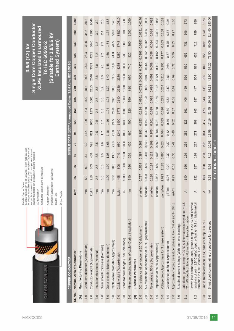
3.6/
6 (7
.2) k
VSi
ngle
Cor
e C
oppe
r Con
duct
orXL
PE In
sula
ted
Una
rmou
red
To IE
C 6
0502
-2(S
uita
ble
for 3
.8/6
.6 k
V Ea
rthe
d Sy
stem
)
Met
allic
Cop
per
Scr
een
(Cop
per
scre
en c
an b
e of
Cu
wire
s +
ope
n he
lix C
u ta
pe
or c
oppe
r ta
pe (
The
deta
ils g
iven
in b
elow
Tab
le a
re f
or
copp
er ta
pe s
cree
ned
cabl
es).
For c
oppe
r wire
scr
eene
d ca
bles
the
det
ails
can
be
give
n on
spe
cific
req
uest
.)
X lP
E In
sula
tion
Con
duct
or S
cree
n (S
emi-c
ondu
ctiv
e)
Cop
per
Con
duct
or
Insu
latio
n S
cree
n (S
emi-c
ondu
ctiv
e)
Bin
der
Tape
Out
er S
heat
h
COPP
ER C
OND
UCTO
RSI
NGLE
CO
RE, 2
XCY,
Una
rmou
red
Cabl
es, 3
.6/6
kV
to IE
C 60
502-
2Sr
. No.
Nom
inal
Are
a of
Con
duct
orm
m²
2535
5070
9512
015
018
524
030
040
050
063
080
010
00(A
)M
anuf
actu
ring
Dim
ensi
ons
1.0
Cond
ucto
r dia
met
er (A
ppro
ximat
e)m
m5.
96.
98.
19.
711
.412
.914
.316
.018
.420
.623
.326
.330
.034
.238
.22.
0Co
nduc
tor w
eigh
t (Ap
prox
imat
e)kg
/km
218
303
408
591
821
1035
1277
1601
2110
2640
3383
4272
5640
7286
9046
3.0
Insu
latio
n th
ickne
ss (N
omin
al)
mm
2.5
2.5
2.5
2.5
2.5
2.5
2.5
2.5
2.6
2.8
3.0
3.2
3.2
3.2
3.2
4.0
Out
er s
heat
h th
ickne
ss (N
omin
al)
mm
1.5
1.5
1.6
1.6
1.7
1.7
1.8
1.8
1.9
2.0
2.1
2.2
2.3
2.4
2.6
5.0
Out
er s
heat
h th
ickne
ss (M
inim
um)
mm
1.00
1.00
1.08
1.08
1.16
1.16
1.24
1.24
1.32
1.40
1.48
1.56
1.64
1.72
1.88
6.0
Cabl
e ov
eral
l dia
met
er (A
ppro
ximat
e)m
m17
.018
.019
.521
.023
.024
.526
.028
.030
.533
.537
.041
.044
.550
.054
.57.
0Ca
ble
weig
ht (A
ppro
ximat
e)kg
/km
495
600
740
960
1240
1490
1775
2140
2730
3350
4235
5250
6745
8580
1051
08.
0St
anda
rd d
rum
leng
th (±
5% T
oler
ance
)m
1000
1000
1000
1000
1000
1000
1000
1000
1000
1000
1000
500
500
500
500
9.0
Min
imum
ben
ding
radi
us o
f cab
le (D
urin
g in
stal
latio
n)m
m34
036
039
042
046
049
052
056
061
067
074
082
089
010
0010
90(B
)El
ectri
cal P
aram
eter
s1.
0DC
resis
tanc
e of
con
duct
or a
t 20
°C (M
axim
um)
ohm
/km
0.
727
0.52
40.
387
0.26
80.
193
0.15
30.
124
0.09
910.
0754
0.06
010.
0470
0.03
660.
0283
0.02
210.
0176
2.0
AC re
sista
nce
of c
ondu
ctor
at 9
0 °C
(Ap
prox
imat
e)oh
m/k
m
0.92
80.
669
0.49
40.
343
0.24
70.
197
0.16
00.
128
0.09
90.
080
0.06
40.
052
0.04
20.
036
0.03
13.
0Re
acta
nce
at 5
0 Hz
(App
roxim
ate)
ohm
/km
0.
130
0.12
40.
119
0.10
90.
105
0.10
10.
099
0.09
50.
092
0.09
10.
089
0.08
80.
084
0.08
40.
082
4.0
Impe
danc
e at
50
Hz (A
ppro
ximat
e)oh
m/k
m
0.93
70.
680
0.50
80.
360
0.26
80.
221
0.18
80.
159
0.13
50.
121
0.11
00.
102
0.09
40.
091
0.08
85.
0Vo
ltage
dro
p (A
ppro
ximat
e fo
r 3 p
hase
sys
tem
)v/
amp/
km1.
623
1.17
80.
880
0.62
40.
464
0.38
30.
326
0.27
50.
234
0.21
00.
191
0.17
70.
163
0.15
80.
152
6.0
Capa
citan
ce a
t 50
Hz (A
ppro
ximat
e)mF
/km
0.26
0.29
0.32
0.37
0.42
0.46
0.50
0.54
0.59
0.61
0.64
0.67
0.75
0.86
0.94
7.0
Appr
oxim
ate
char
ging
curre
nt p
er p
hase
at U
o =
3.6
kV a
nd f=
50
Hzm
A/m
0.29
0.33
0.36
0.42
0.48
0.52
0.57
0.61
0.67
0.69
0.72
0.76
0.85
0.97
1.06
8.0
Sust
aine
d cu
rrent
ratin
gs (W
ith b
oth
end
bond
ing)
:-
8.1
Laid
dire
ct, g
roun
d te
mp.
= 2
0 °C
& T
herm
al re
sistiv
ity o
f soi
l = 1
.5
°C m
/W, d
epth
of l
ayin
g =
0.8
m, l
aid
in tr
efoi
l for
mat
ion.
A14
016
619
623
928
532
336
140
646
952
659
065
573
180
687
3
8.2
Draw
n in
to e
arth
enwa
re d
uct,
grou
nd te
mp.
= 2
0 °C
and
The
rmal
re
sistiv
ity o
f soi
l = 1
.5 °C
m/W
, dep
th o
f layin
g =
0.8
m, la
id in
tref
oil
form
atio
n in
One
Com
mon
Duc
tA
132
157
186
227
271
308
343
387
447
504
564
635
712
789
859
8.3
Laid
in tr
efoi
l for
mat
ion
in a
ir, a
mbi
ent t
emp.
= 3
0 °C
A
163
198
238
296
361
417
473
543
641
735
845
956
1095
1241
1373
9.0
Shor
t circ
uit c
urre
nt ra
ting
of c
ondu
ctor
for 1
sec
ond
kA3.
585.
017.
1510
.01
13.5
917
.16
21.4
526
.46
34.3
242
.90
57.2
071
.50
90.0
911
4.40
143.
00
SEC
TIO
N A
- TA
BLE
1

12 MKXXS005 01/08/2015
6/10
(12)
kV
Sing
le C
ore
Cop
per C
ondu
ctor
XLPE
Insu
late
d U
narm
oure
dTo
IEC
605
02-2
(Sui
tabl
e fo
r 6.3
5/11
kV
Eart
hed
Syst
em)
COPP
ER C
OND
UCTO
RSI
NGLE
CO
RE, 2
XCY,
Una
rmou
red
Cabl
es, 6
/10
kV to
IEC
6050
2-2
Sr. N
o.No
min
al A
rea
of C
ondu
ctor
mm
²25
3550
7095
120
150
185
240
300
400
500
630
800
1000
(A)
Man
ufac
turin
g Di
men
sion
s1.
0Co
nduc
tor d
iam
eter
(App
roxim
ate)
mm
5.9
6.9
8.1
9.7
11.4
12.9
14.3
16.0
18.4
20.6
23.3
26.3
30.0
34.2
38.2
2.0
Cond
ucto
r wei
ght (
Appr
oxim
ate)
kg/k
m21
830
340
859
182
110
3512
7716
0121
1026
4033
8342
7256
4072
8690
463.
0In
sula
tion
thick
ness
(Nom
inal
)m
m3.
43.
43.
43.
43.
43.
43.
43.
43.
43.
43.
43.
43.
43.
43.
44.
0O
uter
she
ath
thick
ness
(Nom
inal
)m
m1.
51.
61.
61.
71.
71.
81.
81.
92.
02.
02.
12.
22.
32.
52.
65.
0O
uter
she
ath
thick
ness
(Min
imum
)m
m1.
001.
081.
081.
161.
161.
241.
241.
321.
401.
401.
481.
561.
641.
801.
886.
0Ca
ble
over
all d
iam
eter
(App
roxim
ate)
mm
19.0
20.0
21.5
23.0
25.0
26.5
28.0
30.0
32.5
34.5
38.0
41.0
45.0
50.5
54.5
7.0
Cabl
e we
ight
(App
roxim
ate)
kg/k
m55
067
080
510
4013
1515
8018
5522
4028
3034
2042
8052
7567
7086
3510
545
8.0
Stan
dard
dru
m le
ngth
(±5%
Tol
eran
ce)
m10
0010
0010
0010
0010
0010
0010
0010
0010
0010
0010
0050
050
050
050
09.
0M
inim
um b
endi
ng ra
dius
of c
able
(Dur
ing
inst
alla
tion)
mm
380
400
430
460
500
530
560
600
650
690
760
820
900
1010
1090
(B)
Elec
trica
l Par
amet
ers
1.0
DC re
sista
nce
of c
ondu
ctor
at 2
0 °C
(Max
imum
)oh
m/k
m
0.72
70.
524
0.38
70.
268
0.19
30.
153
0.12
40.
0991
0.07
540.
0601
0.04
700.
0366
0.02
830.
0221
0.01
762.
0AC
resis
tanc
e of
con
duct
or a
t 90
°C (
Appr
oxim
ate)
ohm
/km
0.
928
0.66
90.
494
0.34
30.
247
0.19
60.
160
0.12
80.
099
0.08
00.
064
0.05
20.
042
0.03
60.
031
3.0
Reac
tanc
e at
50
Hz (A
ppro
ximat
e)oh
m/k
m
0.13
70.
131
0.12
50.
115
0.11
00.
106
0.10
30.
100
0.09
60.
093
0.09
00.
088
0.08
50.
084
0.08
24.
0Im
peda
nce
at 5
0 Hz
(App
roxim
ate)
ohm
/km
0.
938
0.68
20.
510
0.36
20.
270
0.22
30.
190
0.16
20.
138
0.12
30.
110
0.10
20.
095
0.09
10.
088
5.0
Volta
ge d
rop
(App
roxim
ate
for 3
pha
se s
yste
m)
v/am
p/km
1.62
51.
181
0.88
30.
627
0.46
80.
386
0.32
90.
281
0.23
90.
213
0.19
10.
177
0.16
50.
158
0.15
26.
0Ca
pacit
ance
at 5
0 Hz
(App
roxim
ate)
mF/k
m0.
210.
230.
250.
290.
320.
350.
380.
420.
470.
510.
570.
630.
710.
810.
897.
0Ap
prox
imat
e ch
argin
g cu
rrent
per
pha
se a
t Uo
= 6
kV a
nd f=
50
Hzm
A/m
0.40
0.43
0.47
0.55
0.60
0.66
0.72
0.79
0.89
0.96
1.07
1.19
1.34
1.53
1.68
8.0
Sust
aine
d cu
rrent
ratin
gs (W
ith b
oth
end
bond
ing)
:-
8.1
Laid
dire
ct, g
roun
d te
mp.
= 2
0 °C
& T
herm
al re
sistiv
ity o
f soi
l = 1
.5
°C m
/W, d
epth
of l
ayin
g =
0.8
m, l
aid
in tr
efoi
l for
mat
ion.
A14
016
619
623
928
532
336
140
646
952
659
065
573
180
687
3
8.2
Draw
n in
to e
arth
enwa
re d
uct,
grou
nd te
mp.
= 2
0 °C
and
The
rmal
re
sistiv
ity o
f soi
l = 1
.5 °C
m/W
, dep
th o
f layin
g =
0.8
m, la
id in
tref
oil
form
atio
n in
One
Com
mon
Duc
tA
132
157
186
227
271
308
343
387
447
504
564
635
712
789
859
8.3
Laid
in tr
efoi
l for
mat
ion
in a
ir, a
mbi
ent t
emp.
= 3
0 °C
A
163
198
238
296
361
417
473
543
641
735
845
956
1095
1241
1373
9.0
Shor
t circ
uit c
urre
nt ra
ting
of c
ondu
ctor
for 1
sec
ond
kA3.
585.
017.
1510
.01
13.5
917
.16
21.4
526
.46
34.3
242
.90
57.2
071
.50
90.0
911
4.40
143.
00
SEC
TIO
N A
- TA
BLE
2
Met
allic
Cop
per
Scr
een
(Cop
per
scre
en c
an b
e of
Cu
wire
s +
ope
n he
lix C
u ta
pe
or c
oppe
r ta
pe (
The
deta
ils g
iven
in b
elow
Tab
le a
re f
or
copp
er ta
pe s
cree
ned
cabl
es).
For c
oppe
r wire
scr
eene
d ca
bles
the
det
ails
can
be
give
n on
spe
cific
req
uest
.)
XlP
E In
sula
tion
Con
duct
or S
cree
n (S
emi-c
ondu
ctiv
e)
Cop
per
Con
duct
or
Insu
latio
n S
cree
n (S
emi-c
ondu
ctiv
e)
Bin
der
Tape
Out
er S
heat
h

13MKXXS005 01/08/2015
8.7/
15 (1
7.5)
kV
Sing
le C
ore
Cop
per C
ondu
ctor
XLPE
Insu
late
d U
narm
oure
dTo
IEC
605
02-2
(Sui
tabl
e fo
r 8.7
/15
kV
Eart
hed
Syst
em)
COPP
ER C
OND
UCTO
RSI
NGLE
CO
RE, 2
XCY,
Una
rmou
red
Cabl
es, 8
.7/1
5 kV
to IE
C 60
502-
2Sr
. No.
Nom
inal
Are
a of
Con
duct
orm
m²
2535
5070
9512
015
018
524
030
040
050
063
080
010
00(A
)M
anuf
actu
ring
Dim
ensi
ons
1.0
Cond
ucto
r dia
met
er (A
ppro
ximat
e)m
m5.
96.
98.
19.
711
.412
.914
.316
.018
.420
.623
.326
.330
.034
.238
.22.
0Co
nduc
tor w
eigh
t (Ap
prox
imat
e)kg
/km
218
303
408
591
821
1035
1277
1601
2110
2640
3383
4272
5640
7286
9046
3.0
Insu
latio
n th
ickne
ss (N
omin
al)
mm
4.5
4.5
4.5
4.5
4.5
4.5
4.5
4.5
4.5
4.5
4.5
4.5
4.5
4.5
4.5
4.0
Out
er s
heat
h th
ickne
ss (N
omin
al)
mm
1.6
1.7
1.7
1.7
1.8
1.9
1.9
2.0
2.0
2.1
2.2
2.3
2.4
2.5
2.7
5.0
Out
er s
heat
h th
ickne
ss (M
inim
um)
mm
1.08
1.16
1.16
1.16
1.24
1.32
1.32
1.40
1.40
1.48
1.56
1.64
1.72
1.80
1.96
6.0
Cabl
e ov
eral
l dia
met
er (A
ppro
ximat
e)m
m21
.522
.524
.025
.527
.529
.030
.532
.534
.537
.040
.543
.547
.552
.557
.07.
0Ca
ble
weig
ht (A
ppro
ximat
e)kg
/km
635
760
900
1130
1420
1695
1975
2365
2950
3565
4440
5445
6955
8815
1076
58.
0St
anda
rd d
rum
leng
th (±
5% T
oler
ance
)m
1000
1000
1000
1000
1000
1000
1000
1000
1000
1000
500
500
500
500
500
9.0
Min
imum
ben
ding
radi
us o
f cab
le (D
urin
g in
stal
latio
n)m
m43
045
048
051
055
058
061
065
069
074
081
087
095
010
5011
40(B
)El
ectri
cal P
aram
eter
s1.
0DC
resis
tanc
e of
con
duct
or a
t 20
°C (M
axim
um)
ohm
/km
0.
727
0.52
40.
387
0.26
80.
193
0.15
30.
124
0.09
910.
0754
0.06
010.
0470
0.03
660.
0283
0.02
210.
0176
2.0
AC re
sista
nce
of c
ondu
ctor
at 9
0 °C
(Ap
prox
imat
e)oh
m/k
m
0.92
80.
669
0.49
40.
343
0.24
70.
196
0.16
00.
128
0.09
90.
080
0.06
40.
051
0.04
20.
035
0.03
13.
0Re
acta
nce
at 5
0 Hz
(App
roxim
ate)
ohm
/km
0.
145
0.13
80.
132
0.12
20.
116
0.11
20.
109
0.10
50.
100
0.09
70.
094
0.09
10.
089
0.08
70.
085
4.0
Impe
danc
e at
50
Hz (A
ppro
ximat
e)oh
m/k
m
0.93
90.
683
0.51
10.
364
0.27
30.
226
0.19
40.
166
0.14
10.
126
0.11
40.
104
0.09
80.
094
0.09
05.
0Vo
ltage
dro
p (A
ppro
ximat
e fo
r 3 p
hase
sys
tem
)v/
amp/
km1.
626
1.18
30.
885
0.63
00.
473
0.39
10.
336
0.28
80.
244
0.21
80.
197
0.18
00.
170
0.16
30.
156
6.0
Capa
citan
ce a
t 50
Hz (A
ppro
ximat
e)mF
/km
0.17
0.19
0.21
0.23
0.26
0.28
0.30
0.33
0.37
0.40
0.45
0.49
0.55
0.63
0.69
7.0
Appr
oxim
ate
char
ging
curre
nt p
er p
hase
at U
o =
8.7
kV a
nd f=
50
Hzm
A/m
0.46
0.52
0.57
0.63
0.71
0.77
0.82
0.90
1.01
1.09
1.23
1.34
1.50
1.72
1.89
8.0
Sust
aine
d cu
rrent
ratin
gs (W
ith b
oth
end
bond
ing)
:-
8.1
Laid
dire
ct, g
roun
d te
mp.
= 2
0 °C
& T
herm
al re
sistiv
ity o
f soi
l = 1
.5
°C m
/W, d
epth
of l
ayin
g =
0.8
m, l
aid
in tr
efoi
l for
mat
ion.
A14
016
619
623
928
532
336
140
646
952
659
065
573
180
687
3
8.2
Draw
n in
to e
arth
enwa
re d
uct,
grou
nd te
mp.
= 2
0 °C
and
The
rmal
re
sistiv
ity o
f soi
l = 1
.5 °C
m/W
, dep
th o
f layin
g =
0.8
m, la
id in
tref
oil
form
atio
n in
One
Com
mon
Duc
tA
132
157
186
227
271
308
343
387
447
504
564
635
712
789
859
8.3
Laid
in tr
efoi
l for
mat
ion
in a
ir, a
mbi
ent t
emp.
= 3
0 °C
A
163
198
238
296
361
417
473
543
641
735
845
956
1095
1241
1373
9.0
Shor
t circ
uit c
urre
nt ra
ting
of c
ondu
ctor
for 1
sec
ond
kA3.
585.
017.
1510
.01
13.5
917
.16
21.4
526
.46
34.3
242
.90
57.2
071
.50
90.0
911
4.40
143.
00
SEC
TIO
N A
- TA
BLE
3
Met
allic
Cop
per
Scr
een
(Cop
per
scre
en c
an b
e of
Cu
wire
s +
ope
n he
lix C
u ta
pe
or c
oppe
r ta
pe (
The
deta
ils g
iven
in b
elow
Tab
le a
re f
or
copp
er ta
pe s
cree
ned
cabl
es).
For c
oppe
r wire
scr
eene
d ca
bles
the
det
ails
can
be
give
n on
spe
cific
req
uest
.)
XlP
E In
sula
tion
Con
duct
or S
cree
n (S
emi-c
ondu
ctiv
e)
Cop
per
Con
duct
or
Insu
latio
n S
cree
n (S
emi-c
ondu
ctiv
e)
Bin
der
Tape
Out
er S
heat
h

14 MKXXS005 01/08/2015
12/2
0 (2
4) k
VSi
ngle
Cor
e C
oppe
r Con
duct
orXL
PE In
sula
ted
Una
rmou
red
To IE
C 6
0502
-2(S
uita
ble
for 1
2.7/
22 k
V Ea
rthe
d Sy
stem
)
COPP
ER C
OND
UCTO
RSI
NGLE
CO
RE, 2
XCY,
Una
rmou
red
Cabl
es, 1
2/20
kV
to IE
C 60
502-
2Sr
. No.
Nom
inal
Are
a of
Con
duct
orm
m²
3550
7095
120
150
185
240
300
400
500
630
800
1000
(A)
Man
ufac
turin
g Di
men
sion
s1.
0Co
nduc
tor d
iam
eter
(App
roxim
ate)
mm
6.9
8.1
9.7
11.4
12.9
14.3
16.0
18.4
20.6
23.3
26.3
30.0
34.2
38.2
2.0
Cond
ucto
r wei
ght (
Appr
oxim
ate)
kg/k
m30
340
859
182
110
3512
7716
0121
1026
4033
8342
7256
4072
8690
463.
0In
sula
tion
thick
ness
(Nom
inal
)m
m5.
55.
55.
55.
55.
55.
55.
55.
55.
55.
55.
55.
55.
55.
54.
0O
uter
she
ath
thick
ness
(Nom
inal
)m
m1.
71.
81.
81.
91.
92.
02.
02.
12.
22.
32.
42.
52.
62.
75.
0O
uter
she
ath
thick
ness
(Min
imum
)m
m1.
161.
241.
241.
321.
321.
401.
401.
481.
561.
641.
721.
801.
881.
966.
0Ca
ble
over
all d
iam
eter
(App
roxim
ate)
mm
25.0
26.0
28.0
29.5
31.0
32.5
34.5
37.0
39.5
43.0
46.0
50.0
55.0
59.5
7.0
Cabl
e we
ight
(App
roxim
ate)
kg/k
m84
510
0512
4015
4018
0021
0524
8530
9537
1546
0556
2571
5090
2510
965
8.0
Stan
dard
dru
m le
ngth
(±5%
Tol
eran
ce)
m10
0010
0010
0010
0010
0010
0010
0010
0050
050
050
050
050
050
09.
0M
inim
um b
endi
ng ra
dius
of c
able
(Dur
ing
inst
alla
tion)
mm
500
520
560
590
620
650
690
740
790
860
920
1000
1100
1190
(B)
Elec
trica
l Par
amet
ers
1.0
DC re
sista
nce
of c
ondu
ctor
at 2
0 °C
(Max
imum
)oh
m/k
m
0.52
40.
387
0.26
80.
193
0.15
30.
124
0.09
910.
0754
0.06
010.
0470
0.03
660.
0283
0.02
210.
0176
2.0
AC re
sista
nce
of c
ondu
ctor
at 9
0 °C
(Ap
prox
imat
e)oh
m/k
m
0.66
90.
494
0.34
30.
247
0.19
60.
160
0.12
80.
098
0.07
90.
063
0.05
10.
042
0.03
50.
030
3.0
Reac
tanc
e at
50
Hz (A
ppro
ximat
e)oh
m/k
m
0.14
50.
137
0.12
80.
121
0.11
60.
113
0.10
90.
104
0.10
10.
098
0.09
50.
092
0.09
00.
088
4.0
Impe
danc
e at
50
Hz (A
ppro
ximat
e)oh
m/k
m
0.68
50.
513
0.36
60.
275
0.22
80.
196
0.16
80.
143
0.12
80.
117
0.10
80.
101
0.09
70.
093
5.0
Volta
ge d
rop
(App
roxim
ate
for 3
pha
se s
yste
m)
v/am
p/km
1.18
60.
889
0.63
40.
476
0.39
50.
339
0.29
10.
248
0.22
20.
203
0.18
70.
175
0.16
80.
161
6.0
Capa
citan
ce a
t 50
Hz (A
ppro
ximat
e)mF
/km
0.16
0.18
0.20
0.22
0.24
0.26
0.28
0.31
0.34
0.38
0.42
0.46
0.53
0.58
7.0
Appr
oxim
ate
char
ging
curre
nt p
er p
hase
at U
o =
12 kV
and
f= 5
0 Hz
mA/
m0.
600.
680.
750.
830.
900.
981.
061.
171.
281.
431.
581.
732.
002.
198.
0Su
stai
ned
curre
nt ra
tings
(With
bot
h en
d bo
ndin
g):-
8.1
Laid
dire
ct, g
roun
d te
mp.
= 2
0 °C
& T
herm
al re
sistiv
ity o
f soi
l = 1
.5
°C m
/W, d
epth
of l
ayin
g =
0.8
m, l
aid
in tr
efoi
l for
mat
ion.
A16
619
623
928
532
336
140
646
952
659
065
573
180
687
3
8.2
Draw
n in
to e
arth
enwa
re d
uct,
grou
nd te
mp.
= 2
0 °C
and
The
rmal
re
sistiv
ity o
f soi
l = 1
.5 °C
m/W
, dep
th o
f layin
g =
0.8
m, la
id in
tref
oil
form
atio
n in
One
Com
mon
Duc
tA
157
186
227
271
308
343
387
447
504
564
635
712
789
859
8.3
Laid
in tr
efoi
l for
mat
ion
in a
ir, a
mbi
ent t
emp.
= 3
0 °C
A
198
238
296
361
417
473
543
641
735
845
956
1095
1241
1373
9.0
Shor
t circ
uit c
urre
nt ra
ting
of c
ondu
ctor
for 1
sec
ond
kA5.
017.
1510
.01
13.5
917
.16
21.4
526
.46
34.3
242
.90
57.2
071
.50
90.0
911
4.40
143.
00
SEC
TIO
N A
- TA
BLE
4
Met
allic
Cop
per
Scr
een
(Cop
per
scre
en c
an b
e of
Cu
wire
s +
ope
n he
lix C
u ta
pe
or c
oppe
r ta
pe (
The
deta
ils g
iven
in b
elow
Tab
le a
re f
or
copp
er ta
pe s
cree
ned
cabl
es).
For c
oppe
r wire
scr
eene
d ca
bles
the
det
ails
can
be
give
n on
spe
cific
req
uest
.)
XlP
E In
sula
tion
Con
duct
or S
cree
n (S
emi-c
ondu
ctiv
e)
Cop
per
Con
duct
or
Insu
latio
n S
cree
n (S
emi-c
ondu
ctiv
e)
Bin
der
Tape
Out
er S
heat
h

15MKXXS005 01/08/2015
18/3
0 (3
6) k
VSi
ngle
Cor
e C
oppe
r Con
duct
orXL
PE In
sula
ted
Una
rmou
red
To IE
C 6
0502
-2(S
uita
ble
for 1
9/33
kV
Eart
hed
Syst
em)
Met
allic
Cop
per
Scr
een
(Cop
per
scre
en c
an b
e of
Cu
wire
s +
ope
n he
lix C
u ta
pe
or c
oppe
r ta
pe (
The
deta
ils g
iven
in b
elow
Tab
le a
re f
or
copp
er ta
pe s
cree
ned
cabl
es).
For c
oppe
r wire
scr
eene
d ca
bles
the
det
ails
can
be
give
n on
spe
cific
req
uest
.)
X lP
E In
sula
tion
Con
duct
or S
cree
n (S
emi-c
ondu
ctiv
e)
Cop
per
Con
duct
or
Insu
latio
n S
cree
n (S
emi-c
ondu
ctiv
e)
Bin
der
Tape
Out
er S
heat
h
COPP
ER C
OND
UCTO
RSI
NGLE
CO
RE, 2
XCY,
Una
rmou
red
Cabl
es, 1
8/30
kV
to IE
C 60
502-
2Sr
. No.
Nom
inal
Are
a of
Con
duct
orm
m²
5070
9512
015
018
524
030
040
050
063
080
010
00(A
)M
anuf
actu
ring
Dim
ensi
ons
1.0
Cond
ucto
r dia
met
er (A
ppro
ximat
e)m
m8.
19.
711
.412
.914
.316
.018
.420
.623
.326
.330
.034
.238
.22.
0Co
nduc
tor w
eigh
t (Ap
prox
imat
e)kg
/km
408
591
821
1035
1277
1601
2110
2640
3383
4272
5640
7286
9046
3.0
Insu
latio
n th
ickne
ss (N
omin
al)
mm
8.0
8.0
8.0
8.0
8.0
8.0
8.0
8.0
8.0
8.0
8.0
8.0
8.0
4.0
Out
er s
heat
h th
ickne
ss (N
omin
al)
mm
1.9
2.0
2.1
2.1
2.1
2.2
2.3
2.3
2.5
2.5
2.7
2.8
2.9
5.0
Out
er s
heat
h th
ickne
ss (M
inim
um)
mm
1.32
1.40
1.48
1.48
1.48
1.56
1.64
1.64
1.80
1.80
1.96
2.04
2.12
6.0
Cabl
e ov
eral
l dia
met
er (A
ppro
ximat
e)m
m31
.533
.035
.036
.538
.040
.042
.544
.548
.051
.055
.560
.564
.57.
0Ca
ble
weig
ht (A
ppro
ximat
e)kg
/km
1255
1520
1835
2110
2410
2820
3450
4075
5010
6035
7615
9535
1151
08.
0St
anda
rd d
rum
leng
th (±
5% T
oler
ance
)m
1000
1000
1000
1000
1000
500
500
500
500
500
500
500
500
9.0
Min
imum
ben
ding
radi
us o
f cab
le (D
urin
g in
stal
latio
n)m
m63
066
070
073
076
080
085
089
096
010
2011
1012
1012
90(B
)El
ectri
cal P
aram
eter
s1.
0DC
resis
tanc
e of
con
duct
or a
t 20
°C (M
axim
um)
ohm
/km
0.
387
0.26
80.
193
0.15
30.
124
0.09
910.
0754
0.06
010.
0470
0.03
660.
0283
0.02
210.
0176
2.0
AC re
sista
nce
of c
ondu
ctor
at 9
0 °C
(Ap
prox
imat
e)oh
m/k
m
0.49
40.
343
0.24
70.
196
0.15
90.
128
0.09
80.
079
0.06
30.
051
0.04
10.
034
0.03
03.
0Re
acta
nce
at 5
0 Hz
(App
roxim
ate)
ohm
/km
0.
149
0.13
80.
131
0.12
60.
123
0.11
80.
113
0.10
90.
105
0.10
10.
098
0.09
60.
093
4.0
Impe
danc
e at
50
Hz (A
ppro
ximat
e)oh
m/k
m
0.51
60.
370
0.28
00.
233
0.20
10.
174
0.15
00.
135
0.12
20.
113
0.10
60.
102
0.09
85.
0Vo
ltage
dro
p (A
ppro
ximat
e fo
r 3 p
hase
sys
tem
)v/
amp/
km0.
894
0.64
10.
485
0.40
40.
348
0.30
10.
260
0.23
40.
211
0.19
60.
184
0.17
70.
170
6.0
Capa
citan
ce a
t 50
Hz (A
ppro
ximat
e)mF
/km
0.14
0.15
0.17
0.18
0.20
0.21
0.23
0.25
0.28
0.30
0.34
0.38
0.42
7.0
Appr
oxim
ate
char
ging
curre
nt p
er p
hase
at U
o =
18 kV
and
f= 5
0 Hz
mA/
m0.
790.
850.
961.
021.
131.
191.
301.
411.
581.
701.
922.
152.
388.
0Su
stai
ned
curre
nt ra
tings
(With
bot
h en
d bo
ndin
g):-
8.1
Laid
dire
ct, g
roun
d te
mp.
= 2
0 °C
& T
herm
al re
sistiv
ity o
f soi
l = 1
.5
°C m
/W, d
epth
of l
ayin
g =
0.8
m, l
aid
in tr
efoi
l for
mat
ion.
A19
623
928
532
336
140
646
952
659
065
573
180
687
3
8.2
Draw
n in
to e
arth
enwa
re d
uct,
grou
nd te
mp.
= 2
0 °C
and
The
rmal
re
sistiv
ity o
f soi
l = 1
.5 °C
m/W
, dep
th o
f layin
g =
0.8
m, la
id in
tref
oil
form
atio
n in
One
Com
mon
Duc
tA
186
227
271
308
343
387
447
504
564
635
712
789
859
8.3
Laid
in tr
efoi
l for
mat
ion
in a
ir, a
mbi
ent t
emp.
= 3
0 °C
A
238
296
361
417
473
543
641
735
845
956
1095
1241
1373
9.0
Shor
t circ
uit c
urre
nt ra
ting
of c
ondu
ctor
for 1
sec
ond
kA7.
1510
.01
13.5
917
.16
21.4
526
.46
34.3
242
.90
57.2
071
.50
90.0
911
4.40
143.
00
SEC
TIO
N A
- TA
BLE
5

16 MKXXS005 01/08/2015
3.6/
6 (7
.2) k
VSi
ngle
Cor
e A
lum
iniu
m C
ondu
ctor
XLPE
Insu
late
d U
narm
oure
dTo
IEC
605
02-2
(Sui
tabl
e fo
r 3.8
/6.6
kV
Eart
hed
Syst
em)
Met
allic
Cop
per
Scr
een
(Cop
per
scre
en c
an b
e of
Cu
wire
s +
ope
n he
lix C
u ta
pe
or c
oppe
r ta
pe (
The
deta
ils g
iven
in b
elow
Tab
le a
re f
or
copp
er t
ape
scre
ened
cab
les)
. For
cop
per
wire
scr
eene
d ca
bles
the
det
ails
can
be
give
n on
spe
cific
req
uest
.)
XlP
E In
sula
tion
Con
duct
or S
cree
n (S
emi-c
ondu
ctiv
e)
Alu
min
ium
Con
duct
or
Insu
latio
n S
cree
n (S
emi-c
ondu
ctiv
e)
Bin
der
Tape
Out
er S
heat
h
ALUM
INIU
M C
OND
UCTO
RSI
NGLE
CO
RE, A
2XCY
, Una
rmou
red
Cabl
es, 3
.6/6
kV
to IE
C 60
502-
2Sr
. No.
Nom
inal
Are
a of
Con
duct
orm
m²
2535
5070
9512
015
018
524
030
040
050
063
080
010
00(A
)M
anuf
actu
ring
Dim
ensi
ons
1.0
Cond
ucto
r dia
met
er (A
ppro
ximat
e)m
m5.
96.
98.
19.
711
.412
.914
.316
.018
.420
.623
.326
.330
.034
.238
.22.
0Co
nduc
tor w
eigh
t (Ap
prox
imat
e)kg
/km
6792
125
182
251
317
390
493
646
803
1027
1307
1721
2188
2759
3.0
Insu
latio
n th
ickne
ss (N
omin
al)
mm
2.5
2.5
2.5
2.5
2.5
2.5
2.5
2.5
2.6
2.8
3.0
3.2
3.2
3.2
3.2
4.0
Out
er s
heat
h th
ickne
ss (N
omin
al)
mm
1.5
1.5
1.6
1.6
1.7
1.7
1.8
1.8
1.9
2.0
2.1
2.2
2.3
2.4
2.6
5.0
Out
er s
heat
h th
ickne
ss (M
inim
um)
mm
1.00
1.00
1.08
1.08
1.16
1.16
1.24
1.24
1.32
1.40
1.48
1.56
1.64
1.72
1.88
6.0
Cabl
e ov
eral
l dia
met
er (A
ppro
ximat
e)m
m17
.018
.019
.521
.023
.024
.526
.028
.030
.533
.537
.041
.044
.550
.054
.57.
0Ca
ble
weig
ht (A
ppro
ximat
e)kg
/km
340
390
460
550
670
770
885
1030
1265
1515
1875
2285
2825
3480
4225
8.0
Stan
dard
dru
m le
ngth
(±5%
Tol
eran
ce)
m10
0010
0010
0010
0010
0010
0010
0010
0010
0010
0010
0050
050
050
050
09.
0M
inim
um b
endi
ng ra
dius
of c
able
(Dur
ing
inst
alla
tion)
mm
340
360
390
420
460
490
520
560
610
670
740
820
890
1000
1090
(B)
Elec
trica
l Par
amet
ers
1.0
DC re
sista
nce
of c
ondu
ctor
at 2
0 °C
(Max
imum
)oh
m/k
m
1.20
0.86
80.
641
0.44
30.
320
0.25
30.
206
0.16
40.
125
0.10
00.
0778
0.06
050.
0469
0.03
670.
0291
2.0
AC re
sista
nce
of c
ondu
ctor
at 9
0 °C
(Ap
prox
imat
e)oh
m/k
m
1.54
1.11
0.82
30.
569
0.41
10.
325
0.26
50.
212
0.16
20.
130
0.10
20.
081
0.06
50.
052
0.04
43.
0Re
acta
nce
at 5
0 Hz
(App
roxim
ate)
ohm
/km
0.
130
0.12
40.
119
0.10
90.
105
0.10
10.
099
0.09
50.
092
0.09
10.
089
0.08
80.
084
0.08
40.
082
4.0
Impe
danc
e at
50
Hz (A
ppro
ximat
e)oh
m/k
m
1.55
1.12
0.83
20.
579
0.42
40.
340
0.28
30.
232
0.18
60.
159
0.13
50.
120
0.10
60.
099
0.09
35.
0Vo
ltage
dro
p (A
ppro
ximat
e fo
r 3 p
hase
sys
tem
)v/
amp/
km2.
685
1.94
01.
441
1.00
30.
734
0.58
90.
490
0.40
20.
322
0.27
50.
234
0.20
80.
184
0.17
10.
161
6.0
Capa
citan
ce a
t 50
Hz (A
ppro
ximat
e)mF
/km
0.26
0.29
0.32
0.37
0.42
0.46
0.50
0.54
0.59
0.61
0.64
0.67
0.75
0.86
0.94
7.0
Appr
oxim
ate
char
ging
curre
nt p
er p
hase
at U
o =
3.6
kV a
nd f=
50
Hzm
A/m
0.29
0.33
0.36
0.42
0.48
0.52
0.57
0.61
0.67
0.69
0.72
0.76
0.85
0.97
1.06
8.0
Sust
aine
d cu
rrent
ratin
gs (W
ith b
oth
end
bond
ing)
:-
8.1
Laid
dire
ct, g
roun
d te
mp.
= 2
0 °C
& T
herm
al re
sistiv
ity o
f soi
l = 1
.5
°C m
/W, d
epth
of l
ayin
g =
0.8
m, l
aid
in tr
efoi
l for
mat
ion.
A10
812
915
218
622
125
228
131
736
741
447
052
859
967
274
3
8.2
Draw
n in
to e
arth
enwa
re d
uct,
grou
nd te
mp.
= 2
0 °C
and
The
rmal
re
sistiv
ity o
f soi
l = 1
.5 °C
m/W
, dep
th o
f layin
g =
0.8
m, la
id in
tref
oil
form
atio
n in
One
Com
mon
Duc
tA
102
122
144
176
210
240
267
303
351
397
451
512
583
658
731
8.3
Laid
in tr
efoi
l for
mat
ion
in a
ir, a
mbi
ent t
emp.
= 3
0 °C
A
127
154
184
230
280
324
368
424
502
577
673
770
896
1033
1167
9.0
Shor
t circ
uit c
urre
nt ra
ting
of c
ondu
ctor
for 1
sec
ond
kA2.
353.
294.
706.
588.
9311
.28
14.1
017
.39
22.5
628
.20
37.6
047
.00
59.2
275
.20
94.0
0
SEC
TIO
N A
- TA
BLE
6

17MKXXS005 01/08/2015
6/10
(12)
kV
Sing
le C
ore
Alu
min
ium
Con
duct
or
XLPE
Insu
late
d U
narm
oure
d To
IEC
605
02-2
(Sui
tabl
e fo
r 6.3
5/11
kV
Eart
hed
Syst
em)
ALUM
INIU
M C
OND
UCTO
RSI
NGLE
CO
RE, A
2XCY
, Una
rmou
red
Cabl
es, 6
/10
kV to
IEC
6050
2-2
Sr. N
o.No
min
al A
rea
of C
ondu
ctor
mm
²25
3550
7095
120
150
185
240
300
400
500
630
800
1000
(A)
Man
ufac
turin
g Di
men
sion
s1.
0Co
nduc
tor d
iam
eter
(App
roxim
ate)
mm
5.9
6.9
8.1
9.7
11.4
12.9
14.3
16.0
18.4
20.6
23.3
26.3
30.0
34.2
38.2
2.0
Cond
ucto
r wei
ght (
Appr
oxim
ate)
kg/k
m67
9212
518
225
131
739
049
364
680
310
2713
0717
2121
8827
593.
0In
sula
tion
thick
ness
(Nom
inal
)m
m3.
43.
43.
43.
43.
43.
43.
43.
43.
43.
43.
43.
43.
43.
43.
44.
0O
uter
she
ath
thick
ness
(Nom
inal
)m
m1.
51.
61.
61.
71.
71.
81.
81.
92.
02.
02.
12.
22.
32.
52.
65.
0O
uter
she
ath
thick
ness
(Min
imum
)m
m1.
001.
081.
081.
161.
161.
241.
241.
321.
401.
401.
481.
561.
641.
801.
886.
0Ca
ble
over
all d
iam
eter
(App
roxim
ate)
mm
19.0
20.0
21.5
23.0
25.0
26.5
28.0
30.0
32.5
34.5
38.0
41.0
45.0
50.5
54.5
7.0
Cabl
e we
ight
(App
roxim
ate)
kg/k
m40
046
052
063
074
586
097
011
3013
6515
8019
2523
1028
5535
3542
608.
0St
anda
rd d
rum
leng
th (±
5% T
oler
ance
)m
1000
1000
1000
1000
1000
1000
1000
1000
1000
1000
1000
500
500
500
500
9.0
Min
imum
ben
ding
radi
us o
f cab
le (D
urin
g in
stal
latio
n)m
m38
040
043
046
050
053
056
060
065
069
076
082
090
010
1010
90(B
)El
ectri
cal P
aram
eter
s1.
0DC
resis
tanc
e of
con
duct
or a
t 20
°C (M
axim
um)
ohm
/km
1.
200.
868
0.64
10.
443
0.32
00.
253
0.20
60.
164
0.12
50.
100
0.07
780.
0605
0.04
690.
0367
0.02
912.
0AC
resis
tanc
e of
con
duct
or a
t 90
°C (
Appr
oxim
ate)
ohm
/km
1.
541.
110.
823
0.56
90.
411
0.32
50.
265
0.21
20.
162
0.13
00.
102
0.08
10.
064
0.05
20.
044
3.0
Reac
tanc
e at
50
Hz (A
ppro
ximat
e)oh
m/k
m
0.13
70.
131
0.12
50.
115
0.11
00.
106
0.10
30.
100
0.09
60.
093
0.09
00.
088
0.08
50.
084
0.08
24.
0Im
peda
nce
at 5
0 Hz
(App
roxim
ate)
ohm
/km
1.
551.
120.
832
0.58
10.
425
0.34
20.
284
0.23
40.
188
0.16
00.
136
0.12
00.
106
0.09
90.
093
5.0
Volta
ge d
rop
(App
roxim
ate
for 3
pha
se s
yste
m)
v/am
p/km
2.68
51.
940
1.44
11.
006
0.73
60.
592
0.49
20.
405
0.32
60.
277
0.23
60.
208
0.18
40.
171
0.16
16.
0Ca
pacit
ance
at 5
0 Hz
(App
roxim
ate)
mF/k
m0.
210.
230.
250.
290.
320.
350.
380.
420.
470.
510.
570.
630.
710.
810.
897.
0Ap
prox
imat
e ch
argin
g cu
rrent
per
pha
se a
t Uo
= 6
kV a
nd f=
50
Hzm
A/m
0.40
0.43
0.47
0.55
0.60
0.66
0.72
0.79
0.89
0.96
1.07
1.19
1.34
1.53
1.68
8.0
Sust
aine
d cu
rrent
ratin
gs (W
ith b
oth
end
bond
ing)
:-
8.1
Laid
dire
ct, g
roun
d te
mp.
= 2
0 °C
& T
herm
al re
sistiv
ity o
f soi
l = 1
.5
°C m
/W, d
epth
of l
ayin
g =
0.8
m, l
aid
in tr
efoi
l for
mat
ion.
A10
812
915
218
622
125
228
131
736
741
447
052
859
967
274
3
8.2
Draw
n in
to e
arth
enwa
re d
uct,
grou
nd te
mp.
= 2
0 °C
and
The
rmal
re
sistiv
ity o
f soi
l = 1
.5 °C
m/W
, dep
th o
f layin
g =
0.8
m, la
id in
tref
oil
form
atio
n in
One
Com
mon
Duc
tA
102
122
144
176
210
240
267
303
351
397
451
512
583
658
731
8.3
Laid
in tr
efoi
l for
mat
ion
in a
ir, a
mbi
ent t
emp.
= 3
0 °C
A
127
154
184
230
280
324
368
424
502
577
673
770
896
1033
1167
9.0
Shor
t circ
uit c
urre
nt ra
ting
of c
ondu
ctor
for 1
sec
ond
kA2.
353.
294.
706.
588.
9311
.28
14.1
017
.39
22.5
628
.20
37.6
047
.00
59.2
275
.20
94.0
0
SEC
TIO
N A
- TA
BLE
7
Met
allic
Cop
per
Scr
een
(Cop
per
scre
en c
an b
e of
Cu
wire
s +
ope
n he
lix C
u ta
pe
or c
oppe
r ta
pe (
The
deta
ils g
iven
in b
elow
Tab
le a
re f
or
copp
er t
ape
scre
ened
cab
les)
. For
cop
per
wire
scr
eene
d ca
bles
the
det
ails
can
be
give
n on
spe
cific
req
uest
.)
XlP
E In
sula
tion
Con
duct
or S
cree
n (S
emi-c
ondu
ctiv
e)
Alu
min
ium
Con
duct
or
Insu
latio
n S
cree
n (S
emi-c
ondu
ctiv
e)
Bin
der
Tape
Out
er S
heat
h

18 MKXXS005 01/08/2015
8.7/
15 (1
7.5)
kV
Sing
le C
ore
Alu
min
ium
Con
duct
orXL
PE In
sula
ted
Una
rmou
red
To IE
C 6
0502
-2(S
uita
ble
for 8
.7/1
5 kV
Eart
hed
Syst
em)
ALUM
INIU
M C
OND
UCTO
RSI
NGLE
CO
RE, A
2XCY
, Una
rmou
red
Cabl
es, 8
.7/1
5 kV
to IE
C 60
502-
2Sr
. No.
Nom
inal
Are
a of
Con
duct
orm
m²
2535
5070
9512
015
018
524
030
040
050
063
080
010
00(A
)M
anuf
actu
ring
Dim
ensi
ons
1.0
Cond
ucto
r dia
met
er (A
ppro
ximat
e)m
m5.
96.
98.
19.
711
.412
.914
.316
.018
.420
.623
.326
.330
.034
.238
.22.
0Co
nduc
tor w
eigh
t (Ap
prox
imat
e)kg
/km
6792
125
182
251
317
390
493
646
803
1027
1307
1721
2188
2759
3.0
Insu
latio
n th
ickne
ss (N
omin
al)
mm
4.5
4.5
4.5
4.5
4.5
4.5
4.5
4.5
4.5
4.5
4.5
4.5
4.5
4.5
4.5
4.0
Out
er s
heat
h th
ickne
ss (N
omin
al)
mm
1.6
1.7
1.7
1.7
1.8
1.9
1.9
2.0
2.0
2.1
2.2
2.3
2.4
2.5
2.7
5.0
Out
er s
heat
h th
ickne
ss (M
inim
um)
mm
1.08
1.16
1.16
1.16
1.24
1.32
1.32
1.40
1.40
1.48
1.56
1.64
1.72
1.80
1.96
6.0
Cabl
e ov
eral
l dia
met
er (A
ppro
ximat
e)m
m21
.522
.524
.025
.527
.529
.030
.532
.534
.537
.040
.543
.547
.552
.557
.07.
0Ca
ble
weig
ht (A
ppro
ximat
e)kg
/km
485
550
615
720
850
975
1090
1255
1485
1725
2085
2480
3035
3715
4480
8.0
Stan
dard
dru
m le
ngth
(±5%
Tol
eran
ce)
m10
0010
0010
0010
0010
0010
0010
0010
0010
0010
0050
050
050
050
050
09.
0M
inim
um b
endi
ng ra
dius
of c
able
(Dur
ing
inst
alla
tion)
mm
430
450
480
510
550
580
610
650
690
740
810
870
950
1050
1140
(B)
Elec
trica
l Par
amet
ers
1.0
DC re
sista
nce
of c
ondu
ctor
at 2
0 °C
(Max
imum
)oh
m/k
m
1.20
0.86
80.
641
0.44
30.
320
0.25
30.
206
0.16
40.
125
0.10
00.
0778
0.06
050.
0469
0.03
670.
0291
2.0
AC re
sista
nce
of c
ondu
ctor
at 9
0 °C
(Ap
prox
imat
e)oh
m/k
m
1.54
1.11
0.82
30.
569
0.41
10.
325
0.26
50.
212
0.16
20.
130
0.10
20.
081
0.06
40.
052
0.04
33.
0Re
acta
nce
at 5
0 Hz
(App
roxim
ate)
ohm
/km
0.
145
0.13
80.
132
0.12
20.
116
0.11
20.
109
0.10
50.
100
0.09
70.
094
0.09
10.
089
0.08
70.
085
4.0
Impe
danc
e at
50
Hz (A
ppro
ximat
e)oh
m/k
m
1.55
1.12
0.83
40.
582
0.42
70.
344
0.28
70.
237
0.19
00.
162
0.13
90.
122
0.11
00.
101
0.09
55.
0Vo
ltage
dro
p (A
ppro
ximat
e fo
r 3 p
hase
sys
tem
)v/
amp/
km2.
685
1.94
01.
445
1.00
80.
740
0.59
60.
497
0.41
00.
329
0.28
10.
241
0.21
10.
191
0.17
50.
165
6.0
Capa
citan
ce a
t 50
Hz (A
ppro
ximat
e)mF
/km
0.17
0.19
0.21
0.23
0.26
0.28
0.30
0.33
0.37
0.40
0.45
0.49
0.55
0.63
0.69
7.0
Appr
oxim
ate
char
ging
curre
nt p
er p
hase
at U
o =
8.7
kV a
nd f=
50
Hzm
A/m
0.46
0.52
0.57
0.63
0.71
0.77
0.82
0.90
1.01
1.09
1.23
1.34
1.50
1.72
1.89
8.0
Sust
aine
d cu
rrent
ratin
gs (W
ith b
oth
end
bond
ing)
:-
8.1
Laid
dire
ct, g
roun
d te
mp.
= 2
0 °C
& T
herm
al re
sistiv
ity o
f soi
l = 1
.5
°C m
/W, d
epth
of l
ayin
g =
0.8
m, l
aid
in tr
efoi
l for
mat
ion.
A10
812
915
218
622
125
228
131
736
741
447
052
859
967
274
3
8.2
Draw
n in
to e
arth
enwa
re d
uct,
grou
nd te
mp.
= 2
0 °C
and
The
rmal
re
sistiv
ity o
f soi
l = 1
.5 °C
m/W
, dep
th o
f layin
g =
0.8
m, la
id in
tref
oil
form
atio
n in
One
Com
mon
Duc
tA
102
122
144
176
210
240
267
303
351
397
451
512
583
658
731
8.3
Laid
in tr
efoi
l for
mat
ion
in a
ir, a
mbi
ent t
emp.
= 3
0 °C
A
127
154
184
230
280
324
368
424
502
577
673
770
896
1033
1167
9.0
Shor
t circ
uit c
urre
nt ra
ting
of c
ondu
ctor
for 1
sec
ond
kA2.
353.
294.
706.
588.
9311
.28
14.1
017
.39
22.5
628
.20
37.6
047
.00
59.2
275
.20
94.0
0
SEC
TIO
N A
- TA
BLE
8
Met
allic
Cop
per
Scr
een
(Cop
per
scre
en c
an b
e of
Cu
wire
s +
ope
n he
lix C
u ta
pe
or c
oppe
r ta
pe (
The
deta
ils g
iven
in b
elow
Tab
le a
re f
or
copp
er t
ape
scre
ened
cab
les)
. For
cop
per
wire
scr
eene
d ca
bles
the
det
ails
can
be
give
n on
spe
cific
req
uest
.)
XlP
E In
sula
tion
Con
duct
or S
cree
n (S
emi-c
ondu
ctiv
e)
Alu
min
ium
Con
duct
or
Insu
latio
n S
cree
n (S
emi-c
ondu
ctiv
e)
Bin
der
Tape
Out
er S
heat
h

19MKXXS005 01/08/2015
12/2
0 (2
4) k
VSi
ngle
Cor
e A
lum
iniu
m C
ondu
ctor
XLPE
Insu
late
d U
narm
oure
dTo
IEC
605
02-2
(Sui
tabl
e fo
r 12.
7/22
kV
Eart
hed
Syst
em)
ALUM
INIU
M C
OND
UCTO
RSI
NGLE
CO
RE, A
2XCY
, Una
rmou
red
Cabl
es, 1
2/20
kV
to IE
C 60
502-
2Sr
. No.
Nom
inal
Are
a of
Con
duct
orm
m²
3550
7095
120
150
185
240
300
400
500
630
800
1000
(A)
Man
ufac
turin
g Di
men
sion
s1.
0Co
nduc
tor d
iam
eter
(App
roxim
ate)
mm
6.9
8.1
9.7
11.4
12.9
14.3
16.0
18.4
20.6
23.3
26.3
30.0
34.2
38.2
2.0
Cond
ucto
r wei
ght (
Appr
oxim
ate)
kg/k
m92
125
182
251
317
390
493
646
803
1027
1307
1721
2188
2759
3.0
Insu
latio
n th
ickne
ss (N
omin
al)
mm
5.5
5.5
5.5
5.5
5.5
5.5
5.5
5.5
5.5
5.5
5.5
5.5
5.5
5.5
4.0
Out
er s
heat
h th
ickne
ss (N
omin
al)
mm
1.7
1.8
1.8
1.9
1.9
2.0
2.0
2.1
2.2
2.3
2.4
2.5
2.6
2.7
5.0
Out
er s
heat
h th
ickne
ss (M
inim
um)
mm
1.16
1.24
1.24
1.32
1.32
1.40
1.40
1.48
1.56
1.64
1.72
1.80
1.88
1.96
6.0
Cabl
e ov
eral
l dia
met
er (A
ppro
ximat
e)m
m25
.026
.028
.029
.531
.032
.534
.537
.039
.543
.046
.050
.055
.059
.57.
0Ca
ble
weig
ht (A
ppro
ximat
e)kg
/km
635
720
830
970
1085
1215
1375
1630
1880
2250
2660
3230
3925
4680
8.0
Stan
dard
dru
m le
ngth
(±5%
Tol
eran
ce)
m10
0010
0010
0010
0010
0010
0010
0010
0050
050
050
050
050
050
09.
0M
inim
um b
endi
ng ra
dius
of c
able
(Dur
ing
inst
alla
tion)
mm
500
520
560
590
620
650
690
740
790
860
920
1000
1100
1190
(B)
Elec
trica
l Par
amet
ers
1.0
DC re
sista
nce
of c
ondu
ctor
at 2
0 °C
(Max
imum
)oh
m/k
m
0.86
80.
641
0.44
30.
320
0.25
30.
206
0.16
40.
125
0.10
00.
0778
0.06
050.
0469
0.03
670.
0291
2.0
AC re
sista
nce
of c
ondu
ctor
at 9
0 °C
(Ap
prox
imat
e)oh
m/k
m
1.11
0.82
30.
569
0.41
10.
325
0.26
50.
212
0.16
20.
130
0.10
20.
081
0.06
40.
052
0.04
33.
0Re
acta
nce
at 5
0 Hz
(App
roxim
ate)
ohm
/km
0.
145
0.13
70.
128
0.12
10.
116
0.11
30.
109
0.10
40.
101
0.09
80.
095
0.09
20.
090
0.08
84.
0Im
peda
nce
at 5
0 Hz
(App
roxim
ate)
ohm
/km
1.
120.
834
0.58
30.
428
0.34
50.
288
0.23
80.
193
0.16
50.
141
0.12
50.
112
0.10
40.
098
5.0
Volta
ge d
rop
(App
roxim
ate
for 3
pha
se s
yste
m)
v/am
p/km
1.94
01.
445
1.01
00.
741
0.59
80.
499
0.41
20.
334
0.28
60.
244
0.21
70.
194
0.18
00.
170
6.0
Capa
citan
ce a
t 50
Hz (A
ppro
ximat
e)mF
/km
0.16
0.18
0.20
0.22
0.24
0.26
0.28
0.31
0.34
0.38
0.42
0.46
0.53
0.58
7.0
Appr
oxim
ate
char
ging
curre
nt p
er p
hase
at U
o =
12 kV
and
f= 5
0 Hz
mA/
m0.
600.
680.
750.
830.
900.
981.
061.
171.
281.
431.
581.
732.
002.
198.
0Su
stai
ned
curre
nt ra
tings
(With
bot
h en
d bo
ndin
g):-
8.1
Laid
dire
ct, g
roun
d te
mp.
= 2
0 °C
& T
herm
al re
sistiv
ity o
f soi
l = 1
.5
°C m
/W, d
epth
of l
ayin
g =
0.8
m, l
aid
in tr
efoi
l for
mat
ion.
A12
915
218
622
125
228
131
736
741
447
052
859
967
274
3
8.2
Draw
n in
to e
arth
enwa
re d
uct,
grou
nd te
mp.
= 2
0 °C
and
The
rmal
re
sistiv
ity o
f soi
l = 1
.5 °C
m/W
, dep
th o
f layin
g =
0.8
m, la
id in
tref
oil
form
atio
n in
One
Com
mon
Duc
tA
122
144
176
210
240
267
303
351
397
451
512
583
658
731
8.3
Laid
in tr
efoi
l for
mat
ion
in a
ir, a
mbi
ent t
emp.
= 3
0 °C
A
154
184
230
280
324
368
424
502
577
673
770
896
1033
1167
9.0
Shor
t circ
uit c
urre
nt ra
ting
of c
ondu
ctor
for 1
sec
ond
kA3.
294.
706.
588.
9311
.28
14.1
017
.39
22.5
628
.20
37.6
047
.00
59.2
275
.20
94.0
0
SEC
TIO
N A
- TA
BLE
9
Met
allic
Cop
per
Scr
een
(Cop
per
scre
en c
an b
e of
Cu
wire
s +
ope
n he
lix C
u ta
pe
or c
oppe
r ta
pe (
The
deta
ils g
iven
in b
elow
Tab
le a
re f
or
copp
er t
ape
scre
ened
cab
les)
. For
cop
per
wire
scr
eene
d ca
bles
the
det
ails
can
be
give
n on
spe
cific
req
uest
.)
XlP
E In
sula
tion
Con
duct
or S
cree
n (S
emi-c
ondu
ctiv
e)
Alu
min
ium
Con
duct
or
Insu
latio
n S
cree
n (S
emi-c
ondu
ctiv
e)
Bin
der
Tape
Out
er S
heat
h

20 MKXXS005 01/08/2015
18/3
0 (3
6) k
VSi
ngle
Cor
e A
lum
iniu
m C
ondu
ctor
XLPE
Insu
late
d U
narm
oure
dTo
IEC
605
02-2
(Sui
tabl
e fo
r 19/
33 k
VEa
rthe
d Sy
stem
)
Met
allic
Cop
per
Scr
een
(Cop
per
scre
en c
an b
e of
Cu
wire
s +
ope
n he
lix C
u ta
pe
or c
oppe
r ta
pe (
The
deta
ils g
iven
in b
elow
Tab
le a
re f
or
copp
er t
ape
scre
ened
cab
les)
. For
cop
per
wire
scr
eene
d ca
bles
the
det
ails
can
be
give
n on
spe
cific
req
uest
.)
XlP
E In
sula
tion
Con
duct
or S
cree
n (S
emi-c
ondu
ctiv
e)
Alu
min
ium
Con
duct
or
Insu
latio
n S
cree
n (S
emi-c
ondu
ctiv
e)
Bin
der
Tape
Out
er S
heat
h
ALUM
INIU
M C
OND
UCTO
RSI
NGLE
CO
RE, A
2XCY
, Una
rmou
red
Cabl
es, 1
8/30
kV
to IE
C 60
502-
2Sr
. No.
Nom
inal
Are
a of
Con
duct
orm
m²
5070
9512
015
018
524
030
040
050
063
080
010
00(A
)M
anuf
actu
ring
Dim
ensi
ons
1.0
Cond
ucto
r dia
met
er (A
ppro
ximat
e)m
m8.
19.
711
.412
.914
.316
.018
.420
.623
.326
.330
.034
.238
.22.
0Co
nduc
tor w
eigh
t (Ap
prox
imat
e)kg
/km
125
182
251
317
390
493
646
803
1027
1307
1721
2188
2759
3.0
Insu
latio
n th
ickne
ss (N
omin
al)
mm
8.0
8.0
8.0
8.0
8.0
8.0
8.0
8.0
8.0
8.0
8.0
8.0
8.0
4.0
Out
er s
heat
h th
ickne
ss (N
omin
al)
mm
1.9
2.0
2.1
2.1
2.1
2.2
2.3
2.3
2.5
2.5
2.7
2.8
2.9
5.0
Out
er s
heat
h th
ickne
ss (M
inim
um)
mm
1.32
1.40
1.48
1.48
1.48
1.56
1.64
1.64
1.80
1.80
1.96
2.04
2.12
6.0
Cabl
e ov
eral
l dia
met
er (A
ppro
ximat
e)m
m31
.533
.035
.036
.538
.040
.042
.544
.548
.051
.055
.560
.564
.57.
0Ca
ble
weig
ht (A
ppro
ximat
e)kg
/km
970
1110
1265
1390
1520
1710
1990
2240
2655
3070
3695
4435
5225
8.0
Stan
dard
dru
m le
ngth
(±5%
Tol
eran
ce)
m10
0010
0010
0010
0010
0050
050
050
050
050
050
050
050
09.
0M
inim
um b
endi
ng ra
dius
of c
able
(Dur
ing
inst
alla
tion)
mm
630
660
700
730
760
800
850
890
960
1020
1110
1210
1290
(B)
Elec
trica
l Par
amet
ers
1.0
DC re
sista
nce
of c
ondu
ctor
at 2
0 °C
(Max
imum
)oh
m/k
m
0.64
10.
443
0.32
00.
253
0.20
60.
164
0.12
50.
100
0.07
780.
0605
0.04
690.
0367
0.02
912.
0AC
resis
tanc
e of
con
duct
or a
t 90
°C (
Appr
oxim
ate)
ohm
/km
0.
823
0.56
90.
411
0.32
50.
265
0.21
10.
162
0.13
00.
102
0.08
00.
064
0.05
10.
043
3.0
Reac
tanc
e at
50
Hz (A
ppro
ximat
e)oh
m/k
m
0.14
90.
138
0.13
10.
126
0.12
30.
118
0.11
30.
109
0.10
50.
101
0.09
80.
096
0.09
34.
0Im
peda
nce
at 5
0 Hz
(App
roxim
ate)
ohm
/km
0.
836
0.58
50.
431
0.34
90.
292
0.24
20.
198
0.17
00.
146
0.12
90.
117
0.10
90.
102
5.0
Volta
ge d
rop
(App
roxim
ate
for 3
pha
se s
yste
m)
v/am
p/km
1.44
81.
013
0.74
70.
604
0.50
60.
419
0.34
30.
294
0.25
30.
223
0.20
30.
189
0.17
76.
0Ca
pacit
ance
at 5
0 Hz
(App
roxim
ate)
mF/k
m0.
140.
150.
170.
180.
200.
210.
230.
250.
280.
300.
340.
380.
427.
0Ap
prox
imat
e ch
argin
g cu
rrent
per
pha
se a
t Uo
= 18
kV a
nd f=
50
Hzm
A/m
0.79
0.85
0.96
1.02
1.13
1.19
1.30
1.41
1.58
1.70
1.92
2.15
2.38
8.0
Sust
aine
d cu
rrent
ratin
gs (W
ith b
oth
end
bond
ing)
:-
8.1
Laid
dire
ct, g
roun
d te
mp.
= 2
0 °C
& T
herm
al re
sistiv
ity o
f soi
l = 1
.5
°C m
/W, d
epth
of l
ayin
g =
0.8
m, l
aid
in tr
efoi
l for
mat
ion.
A15
218
622
125
228
131
736
741
447
052
859
967
274
3
8.2
Draw
n in
to e
arth
enwa
re d
uct,
grou
nd te
mp.
= 2
0 °C
and
The
rmal
re
sistiv
ity o
f soi
l = 1
.5 °C
m/W
, dep
th o
f layin
g =
0.8
m, la
id in
tref
oil
form
atio
n in
One
Com
mon
Duc
tA
144
176
210
240
267
303
351
397
451
512
583
658
731
8.3
Laid
in tr
efoi
l for
mat
ion
in a
ir, a
mbi
ent t
emp.
= 3
0 °C
A
184
230
280
324
368
424
502
577
673
770
896
1033
1167
9.0
Shor
t circ
uit c
urre
nt ra
ting
of c
ondu
ctor
for 1
sec
ond
kA4.
706.
588.
9311
.28
14.1
017
.39
22.5
628
.20
37.6
047
.00
59.2
275
.20
94.0
0
SEC
TIO
N A
- TA
BLE
10

21MKXXS005 01/08/2015
3.6/
6 (7
.2) k
VSi
ngle
Cor
e C
oppe
r Con
duct
orXL
PE In
sula
ted
Alu
min
ium
Wire
Arm
oure
d To
IEC
605
02-2
(Sui
tabl
e fo
r 3.8
/6.6
kV
Eart
hed
Syst
em)
Bed
ding
Met
allic
Cop
per
Scr
een
(Cop
per
scre
en c
an b
e of
Cu
wire
s +
ope
n he
lix C
u ta
pe
or c
oppe
r ta
pe (
The
deta
ils g
iven
in b
elow
Tab
le a
re f
or
copp
er ta
pe s
cree
ned
cabl
es).
For c
oppe
r wire
scr
eene
d ca
bles
the
det
ails
can
be
give
n on
spe
cific
req
uest
.)
XlP
E In
sula
tion
Con
duct
or S
cree
n (S
emi-c
ondu
ctiv
e)
Cop
per
Con
duct
or
Insu
latio
n S
cree
n (S
emi-c
ondu
ctiv
e)A
lum
iniu
m W
ire A
rmou
rO
uter
She
ath
COPP
ER C
OND
UCTO
RSI
NGLE
CO
RE, 2
XCW
aY, A
lum
iniu
m W
ire A
rmou
red
Cabl
es, 3
.6/6
kV
to IE
C 60
502-
2Sr
. No.
Nom
inal
Are
a of
Con
duct
orm
m²
2535
5070
9512
015
018
524
030
040
050
063
080
010
00(A
)M
anuf
actu
ring
Dim
ensi
ons
1.0
Cond
ucto
r dia
met
er (A
ppro
ximat
e)m
m5.
96.
98.
19.
711
.412
.914
.316
.018
.420
.623
.326
.330
.034
.238
.22.
0Co
nduc
tor w
eigh
t (Ap
prox
imat
e)kg
/km
218
303
408
591
821
1035
1277
1601
2110
2640
3383
4272
5640
7286
9046
3.0
Insu
latio
n th
ickne
ss (N
omin
al)
mm
2.5
2.5
2.5
2.5
2.5
2.5
2.5
2.5
2.6
2.8
3.0
3.2
3.2
3.2
3.2
4.0
Sepa
ratio
n sh
eath
thick
ness
(Nom
inal
)m
m1.
21.
21.
21.
21.
21.
21.
21.
21.
21.
21.
21.
31.
41.
41.
55.
0Ar
mou
r wire
dia
met
er (N
omin
al)
mm
1.6
1.6
1.6
1.6
1.6
1.6
1.6
2.0
2.0
2.0
2.0
2.5
2.5
2.5
2.5
6.0
Out
er s
heat
h th
ickne
ss (N
omin
al)
mm
1.7
1.7
1.8
1.8
1.9
1.9
2.0
2.0
2.1
2.2
2.3
2.5
2.6
2.7
2.9
7.0
Out
er s
heat
h th
ickne
ss (M
inim
um)
mm
1.16
1.16
1.24
1.24
1.32
1.32
1.40
1.40
1.48
1.56
1.64
1.80
1.88
1.96
2.12
8.0
Cabl
e ov
eral
l dia
met
er (A
ppro
ximat
e)m
m22
.023
.024
.526
.028
.029
.531
.033
.536
.039
.042
.547
.552
.057
.061
.59.
0Ca
ble
weig
ht (A
ppro
ximat
e)kg
/km
755
875
1025
1265
1570
1840
2145
2620
3260
3920
4860
6140
7735
9680
1169
510
.0St
anda
rd d
rum
leng
th (±
5% T
oler
ance
)m
1000
1000
1000
1000
1000
1000
1000
1000
1000
500
500
500
500
500
500
11.0
Min
imum
ben
ding
radi
us o
f cab
le (D
urin
g in
stal
latio
n)m
m33
034
536
839
042
044
346
550
354
058
563
871
378
085
592
3(B
)El
ectri
cal P
aram
eter
s( i
)Co
nduc
tor
1.0
DC re
sista
nce
of c
ondu
ctor
at 2
0 °C
(Max
imum
)oh
m/k
m
0.72
70.
524
0.38
70.
268
0.19
30.
153
0.12
40.
0991
0.07
540.
0601
0.04
700.
0366
0.02
830.
0221
0.01
762.
0AC
resis
tanc
e of
con
duct
or a
t 90
°C (
Appr
oxim
ate)
ohm
/km
0.
928
0.66
90.
494
0.34
30.
247
0.19
60.
160
0.12
80.
098
0.07
90.
063
0.05
10.
041
0.03
50.
030
3.0
Reac
tanc
e at
50
Hz (A
ppro
ximat
e)oh
m/k
m
0.14
60.
139
0.13
30.
123
0.11
70.
113
0.11
00.
107
0.10
20.
100
0.09
70.
097
0.09
40.
092
0.09
04.
0Im
peda
nce
at 5
0 Hz
(App
roxim
ate)
ohm
/km
0.
939
0.68
30.
512
0.36
40.
273
0.22
60.
194
0.16
70.
141
0.12
70.
116
0.11
00.
103
0.09
80.
095
5.0
Volta
ge d
rop
(App
roxim
ate
for 3
pha
se s
yste
m)
v/am
p/km
1.62
61.
183
0.88
70.
630
0.47
30.
391
0.33
60.
289
0.24
40.
220
0.20
10.
191
0.17
80.
170
0.16
56.
0Ca
pacit
ance
at 5
0 Hz
(App
roxim
ate)
mF/k
m0.
260.
290.
320.
370.
420.
460.
500.
540.
590.
610.
640.
670.
750.
860.
947.
0Ap
prox
imat
e ch
argin
g cu
rrent
per
pha
se a
t Uo
= 3.
6 kV
and
f =
50 H
zm
A/m
0.29
0.33
0.36
0.42
0.48
0.52
0.57
0.61
0.67
0.69
0.72
0.76
0.85
0.97
1.06
8.0
Sust
aine
d cu
rrent
ratin
gs (W
ith b
oth
end
bond
ing)
:-
8.1
Laid
dire
ct, g
roun
d te
mp.
= 2
0 °C
& T
herm
al re
sistiv
ity o
f soi
l = 1
.5
°C m
/W, d
epth
of l
ayin
g =
0.8
m, l
aid
in tr
efoi
l for
mat
ion.
A13
716
419
323
427
831
534
939
144
649
555
159
364
669
373
1
8.2
Draw
n in
to e
arth
enwa
re d
uct,
grou
nd te
mp.
= 2
0 °C
and
The
rmal
re
sistiv
ity o
f soi
l = 1
.5 °C
m/W
, dep
th o
f layin
g =
0.8
m, la
id in
tref
oil
form
atio
n in
One
Com
mon
Duc
tA
131
155
183
223
265
301
334
376
430
478
534
578
632
682
721
8.3
Laid
in tr
efoi
l for
mat
ion
in a
ir, a
mbi
ent t
emp.
= 3
0 °C
A
162
196
234
291
353
406
460
524
6 11
692
788
873
975
1074
1156
9.0
Shor
t circ
uit c
urre
nt ra
ting
of c
ondu
ctor
for 1
sec
ond
kA3.
585.
017.
1510
.01
13.5
917
.16
21.4
526
.46
34.3
242
.90
57.2
071
.50
90.0
911
4.40
143.
00( i
i )Ar
mou
r1.
0DC
resis
tanc
e at
20
°C (A
ppro
ximat
e)oh
m/k
m
0.60
70.
562
0.52
40.
474
0.43
40.
400
0.38
00.
286
0.25
60.
237
0.21
10.
152
0.13
80.
122
0.11
32.
0AC
resis
tanc
e at
80
°C (A
ppro
ximat
e)oh
m/k
m
0.75
40.
698
0.65
10.
589
0.53
90.
497
0.47
20.
355
0.31
80.
294
0.26
20.
189
0.17
10.
151
0.14
03.
0Sh
ort c
ircui
t cur
rent
ratin
g of
arm
our f
or 1
sec
ond
(App
roxim
ate)
kA4.
274.
614.
955.
465.
976.
496.
839.
0710
.14
10.9
412
.27
17.0
918
.75
21.2
522
.92
SEC
TIO
N B
- TA
BLE
1

22 MKXXS005 01/08/2015
6/10
(12)
kV
Sing
le C
ore
Cop
per C
ondu
ctor
XLPE
Insu
late
d A
lum
iniu
m W
ire A
rmou
red
To IE
C 6
0502
-2(S
uita
ble
for 6
.35/
11 k
VEa
rthe
d Sy
stem
)
Bed
ding
Met
allic
Cop
per
Scr
een
(Cop
per
scre
en c
an b
e of
Cu
wire
s +
ope
n he
lix C
u ta
pe
or c
oppe
r ta
pe (
The
deta
ils g
iven
in b
elow
Tab
le a
re f
or
copp
er ta
pe s
cree
ned
cabl
es).
For c
oppe
r wire
scr
eene
d ca
bles
the
det
ails
can
be
give
n on
spe
cific
req
uest
.)
XlP
E In
sula
tion
Con
duct
or S
cree
n (S
emi-c
ondu
ctiv
e)
Cop
per
Con
duct
or
Insu
latio
n S
cree
n (S
emi-c
ondu
ctiv
e)A
lum
iniu
m W
ire A
rmou
rO
uter
She
ath
COPP
ER C
OND
UCTO
RSI
NGLE
CO
RE, 2
XCW
aY, A
lum
iniu
m W
ire A
rmou
red
Cabl
es, 6
/10
kV to
IEC
6050
2-2
Sr. N
o.No
min
al A
rea
of C
ondu
ctor
mm
²25
3550
7095
120
150
185
240
300
400
500
630
800
1000
(A)
Man
ufac
turin
g Di
men
sion
s1.
0Co
nduc
tor d
iam
eter
(App
roxim
ate)
mm
5.9
6.9
8.1
9.7
11.4
12.9
14.3
16.0
18.4
20.6
23.3
26.3
30.0
34.2
38.2
2.0
Cond
ucto
r wei
ght (
Appr
oxim
ate)
kg/k
m21
830
340
859
182
110
3512
7716
0121
1026
4033
8342
7256
4072
8690
463.
0In
sula
tion
thick
ness
(Nom
inal
)m
m3.
43.
43.
43.
43.
43.
43.
43.
43.
43.
43.
43.
43.
43.
43.
44.
0Se
para
tion
shea
th th
ickne
ss (N
omin
al)
mm
1.2
1.2
1.2
1.2
1.2
1.2
1.2
1.2
1.2
1.2
1.2
1.3
1.4
1.4
1.5
5.0
Arm
our w
ire d
iam
eter
(Nom
inal
)m
m1.
61.
61.
61.
61.
61.
62.
02.
02.
02.
02.
02.
52.
52.
52.
56.
0O
uter
she
ath
thick
ness
(Nom
inal
)m
m1.
71.
81.
81.
91.
92.
02.
12.
12.
22.
22.
42.
52.
62.
72.
97.
0O
uter
she
ath
thick
ness
(Min
imum
)m
m1.
161.
241.
241.
321.
321.
401.
481.
481.
561.
561.
721.
801.
881.
962.
128.
0Ca
ble
over
all d
iam
eter
(App
roxim
ate)
mm
24.0
25.0
26.0
28.0
29.5
31.5
33.5
35.5
38.0
40.0
43.5
48.0
52.0
57.5
62.0
9.0
Cabl
e we
ight
(App
roxim
ate)
kg/k
m83
596
011
1013
7016
6519
5523
5527
4533
8040
0549
4061
7077
6597
1511
745
10.0
Stan
dard
dru
m le
ngth
(±5%
Tol
eran
ce)
m10
0010
0010
0010
0010
0010
0010
0010
0010
0050
050
050
050
050
050
011
.0M
inim
um b
endi
ng ra
dius
of c
able
(Dur
ing
inst
alla
tion)
mm
360
375
390
420
443
473
503
533
570
600
653
720
780
863
930
(B)
Elec
trica
l Par
amet
ers
( i )
Cond
ucto
r1.
0DC
resis
tanc
e of
con
duct
or a
t 20
°C (M
axim
um)
ohm
/km
0.
727
0.52
40.
387
0.26
80.
193
0.15
30.
124
0.09
910.
0754
0.06
010.
0470
0.03
660.
0283
0.02
210.
0176
2.0
AC re
sista
nce
of c
ondu
ctor
at 9
0 °C
(Ap
prox
imat
e)oh
m/k
m
0.92
80.
669
0.49
40.
343
0.24
70.
196
0.16
00.
128
0.09
80.
079
0.06
30.
051
0.04
10.
035
0.03
03.
0Re
acta
nce
at 5
0 Hz
(App
roxim
ate)
ohm
/km
0.
152
0.14
50.
137
0.12
80.
121
0.11
70.
115
0.11
00.
106
0.10
20.
099
0.09
80.
094
0.09
20.
090
4.0
Impe
danc
e at
50
Hz (A
ppro
ximat
e)oh
m/k
m
0.94
00.
685
0.51
30.
366
0.27
50.
228
0.19
70.
169
0.14
40.
129
0.11
70.
110
0.10
30.
098
0.09
55.
0Vo
ltage
dro
p (A
ppro
ximat
e fo
r 3 p
hase
sys
tem
)v/
amp/
km1.
628
1.18
60.
889
0.63
40.
476
0.39
50.
341
0.29
30.
249
0.22
30.
203
0.19
10.
178
0.17
00.
165
6.0
Capa
citan
ce a
t 50
Hz (A
ppro
ximat
e)mF
/km
0.21
0.23
0.25
0.29
0.32
0.35
0.38
0.42
0.47
0.51
0.57
0.63
0.71
0.81
0.89
7.0
Appr
oxim
ate
char
ging
curre
nt p
er p
hase
at U
o =
6 kV
and
f =
50 H
zm
A/m
0.40
0.43
0.47
0.55
0.60
0.66
0.72
0.79
0.89
0.96
1.07
1.19
1.34
1.53
1.68
8.0
Sust
aine
d cu
rrent
ratin
gs (W
ith b
oth
end
bond
ing)
:-
8.1
Laid
dire
ct, g
roun
d te
mp.
= 2
0 °C
& T
herm
al re
sistiv
ity o
f soi
l = 1
.5
°C m
/W, d
epth
of l
ayin
g =
0.8
m, l
aid
in tr
efoi
l for
mat
ion.
A13
716
419
323
427
831
534
939
144
649
555
159
364
669
373
1
8.2
Draw
n in
to e
arth
enwa
re d
uct,
grou
nd te
mp.
= 2
0 °C
and
The
rmal
re
sistiv
ity o
f soi
l = 1
.5 °C
m/W
, dep
th o
f layin
g =
0.8
m, la
id in
tref
oil
form
atio
n in
One
Com
mon
Duc
tA
131
155
183
223
265
301
334
376
430
478
534
578
632
682
721
8.3
Laid
in tr
efoi
l for
mat
ion
in a
ir, a
mbi
ent t
emp.
= 3
0 °C
A
162
196
234
291
353
406
460
524
6 11
692
788
873
975
1074
1156
9.0
Shor
t circ
uit c
urre
nt ra
ting
of c
ondu
ctor
for 1
sec
ond
kA3.
585.
017.
1510
.01
13.5
917
.16
21.4
526
.46
34.3
242
.90
57.2
071
.50
90.0
911
4.40
143.
00( i
i )Ar
mou
r1.
0DC
resis
tanc
e at
20
°C (A
ppro
ximat
e)oh
m/k
m
0.54
20.
506
0.47
40.
434
0.40
00.
370
0.28
60.
270
0.24
30.
226
0.20
70.
152
0.13
80.
122
0.11
12.
0AC
resis
tanc
e at
80
°C (A
ppro
ximat
e)oh
m/k
m
0.67
30.
628
0.58
90.
539
0.49
70.
459
0.35
50.
335
0.30
20.
281
0.25
70.
189
0.17
10.
151
0.13
83.
0Sh
ort c
ircui
t cur
rent
ratin
g of
arm
our f
or 1
sec
ond
(App
roxim
ate)
kA4.
785.
125.
465.
976.
497.
009.
079.
6010
.67
11.4
712
.54
17.0
918
.75
21.2
523
.34
SEC
TIO
N B
- TA
BLE
2

23MKXXS005 01/08/2015
8.7/
15 (1
7.5)
kV
Sing
le C
ore
Cop
per C
ondu
ctor
XLPE
Insu
late
d A
lum
iniu
m W
ire A
rmou
red
To IE
C 6
0502
-2(S
uita
ble
for 8
.7/1
5 kV
Ea
rthe
d Sy
stem
)
Bed
ding
Met
allic
Cop
per
Scr
een
(Cop
per
scre
en c
an b
e of
Cu
wire
s +
ope
n he
lix C
u ta
pe
or c
oppe
r ta
pe (
The
deta
ils g
iven
in b
elow
Tab
le a
re f
or
copp
er ta
pe s
cree
ned
cabl
es).
For c
oppe
r wire
scr
eene
d ca
bles
the
det
ails
can
be
give
n on
spe
cific
req
uest
.)
XlP
E In
sula
tion
Con
duct
or S
cree
n (S
emi-c
ondu
ctiv
e)
Cop
per
Con
duct
or
Insu
latio
n S
cree
n (S
emi-c
ondu
ctiv
e)A
lum
iniu
m W
ire A
rmou
rO
uter
She
ath
COPP
ER C
OND
UCTO
RSI
NGLE
CO
RE, 2
XCW
aY, A
lum
iniu
m W
ire A
rmou
red
Cabl
es, 8
.7/1
5 kV
to IE
C 60
502-
2Sr
. No.
Nom
inal
Are
a of
Con
duct
orm
m²
2535
5070
9512
015
018
524
030
040
050
063
080
010
00(A
)M
anuf
actu
ring
Dim
ensi
ons
1.0
Cond
ucto
r dia
met
er (A
ppro
ximat
e)m
m5.
96.
98.
19.
711
.412
.914
.316
.018
.420
.623
.326
.330
.034
.238
.22.
0Co
nduc
tor w
eigh
t (Ap
prox
imat
e)kg
/km
218
303
408
591
821
1035
1277
1601
2110
2640
3383
4272
5640
7286
9046
3.0
Insu
latio
n th
ickne
ss (N
omin
al)
mm
4.5
4.5
4.5
4.5
4.5
4.5
4.5
4.5
4.5
4.5
4.5
4.5
4.5
4.5
4.5
4.0
Sepa
ratio
n sh
eath
thick
ness
(Nom
inal
)m
m1.
21.
21.
21.
21.
21.
21.
21.
21.
21.
21.
31.
31.
41.
51.
65.
0Ar
mou
r wire
dia
met
er (N
omin
al)
mm
1.6
1.6
1.6
1.6
2.0
2.0
2.0
2.0
2.0
2.0
2.5
2.5
2.5
2.5
2.5
6.0
Out
er s
heat
h th
ickne
ss (N
omin
al)
mm
1.8
1.9
1.9
1.9
2.0
2.1
2.1
2.2
2.3
2.3
2.5
2.6
2.7
2.8
3.0
7.0
Out
er s
heat
h th
ickne
ss (M
inim
um)
mm
1.24
1.32
1.32
1.32
1.40
1.48
1.48
1.56
1.64
1.64
1.80
1.88
1.96
2.04
2.20
8.0
Cabl
e ov
eral
l dia
met
er (A
ppro
ximat
e)m
m26
.027
.528
.530
.033
.034
.536
.037
.540
.542
.547
.550
.554
.559
.564
.59.
0Ca
ble
weig
ht (A
ppro
ximat
e)kg
/km
940
1080
1235
1490
1890
2190
2495
2920
3555
4190
5315
6395
8005
9970
1204
510
.0St
anda
rd d
rum
leng
th (±
5% T
oler
ance
)m
1000
1000
1000
1000
1000
1000
1000
1000
500
500
500
500
500
500
500
11.0
Min
imum
ben
ding
radi
us o
f cab
le (D
urin
g in
stal
latio
n)m
m39
041
342
845
049
551
854
056
360
863
871
375
881
889
396
8(B
)El
ectri
cal P
aram
eter
s( i
)Co
nduc
tor
1.0
DC re
sista
nce
of c
ondu
ctor
at 2
0 °C
(Max
imum
)oh
m/k
m
0.72
70.
524
0.38
70.
268
0.19
30.
153
0.12
40.
0991
0.07
540.
0601
0.04
700.
0366
0.02
830.
0221
0.01
762.
0AC
resis
tanc
e of
con
duct
or a
t 90
°C (
Appr
oxim
ate)
ohm
/km
0.
928
0.66
90.
494
0.34
30.
247
0.19
60.
159
0.12
80.
098
0.07
90.
063
0.05
10.
041
0.03
40.
030
3.0
Reac
tanc
e at
50
Hz (A
ppro
ximat
e)oh
m/k
m
0.15
70.
151
0.14
30.
132
0.12
80.
123
0.11
90.
114
0.11
00.
106
0.10
40.
101
0.09
70.
095
0.09
34.
0Im
peda
nce
at 5
0 Hz
(App
roxim
ate)
ohm
/km
0.
941
0.68
60.
514
0.36
80.
278
0.23
10.
199
0.17
10.
147
0.13
20.
122
0.11
30.
105
0.10
10.
098
5.0
Volta
ge d
rop
(App
roxim
ate
for 3
pha
se s
yste
m)
v/am
p/km
1.63
01.
188
0.89
00.
637
0.48
20.
400
0.34
50.
296
0.25
50.
229
0.21
10.
196
0.18
20.
175
0.17
06.
0Ca
pacit
ance
at 5
0 Hz
(App
roxim
ate)
mF/k
m0.
170.
190.
210.
230.
260.
280.
300.
330.
370.
400.
450.
490.
550.
630.
697.
0Ap
prox
imat
e ch
argin
g cu
rrent
per
pha
se a
t Uo
= 8.
7 kV
and
f =
50 H
zm
A/m
0.46
0.52
0.57
0.63
0.71
0.77
0.82
0.90
1.01
1.09
1.23
1.34
1.50
1.72
1.89
8.0
Sust
aine
d cu
rrent
ratin
gs (W
ith b
oth
end
bond
ing)
:-
8.1
Laid
dire
ct, g
roun
d te
mp.
= 2
0 °C
& T
herm
al re
sistiv
ity o
f soi
l = 1
.5
°C m
/W, d
epth
of l
ayin
g =
0.8
m, l
aid
in tr
efoi
l for
mat
ion.
A13
716
419
323
427
831
534
939
144
649
555
159
364
669
373
1
8.2
Draw
n in
to e
arth
enwa
re d
uct,
grou
nd te
mp.
= 2
0 °C
and
The
rmal
re
sistiv
ity o
f soi
l = 1
.5 °C
m/W
, dep
th o
f layin
g =
0.8
m, la
id in
tref
oil
form
atio
n in
One
Com
mon
Duc
tA
131
155
183
223
265
301
334
376
430
478
534
578
632
682
721
8.3
Laid
in tr
efoi
l for
mat
ion
in a
ir, a
mbi
ent t
emp.
= 3
0 °C
A
162
196
234
291
353
406
460
524
6 11
692
788
873
975
1074
1156
9.0
Shor
t circ
uit c
urre
nt ra
ting
of c
ondu
ctor
for 1
sec
ond
kA3.
585.
017.
1510
.01
13.5
917
.16
21.4
526
.46
34.3
242
.90
57.2
071
.50
90.0
911
4.40
143.
00( i
i )Ar
mou
r1.
0DC
resis
tanc
e at
20
°C (A
ppro
ximat
e)oh
m/k
m
0.47
40.
447
0.42
20.
389
0.29
40.
278
0.26
30.
243
0.22
60.
211
0.15
50.
141
0.13
00.
115
0.10
52.
0AC
resis
tanc
e at
80
°C (A
ppro
ximat
e)oh
m/k
m
0.58
90.
555
0.52
40.
483
0.36
50.
345
0.32
70.
302
0.28
10.
262
0.19
20.
175
0.16
10.
143
0.13
03.
0Sh
ort c
ircui
t cur
rent
ratin
g of
arm
our f
or 1
sec
ond
(App
roxim
ate)
kA5.
465.
806.
156.
668.
809.
349.
8710
.67
11.4
712
.27
16.6
718
.34
20.0
022
.50
24.5
9SE
CTI
ON
B -
TAB
LE 3

24 MKXXS005 01/08/2015
12/2
0 (2
4) k
VSi
ngle
Cor
e C
oppe
r Con
duct
orXL
PE In
sula
ted
Alu
min
ium
Wire
Arm
oure
dTo
IEC
605
02-2
(Sui
tabl
e fo
r 12.
7/22
kV
Eart
hed
Syst
em)
Bed
ding
Met
allic
Cop
per
Scr
een
(Cop
per
scre
en c
an b
e of
Cu
wire
s +
ope
n he
lix C
u ta
pe
or c
oppe
r ta
pe (
The
deta
ils g
iven
in b
elow
Tab
le a
re f
or
copp
er ta
pe s
cree
ned
cabl
es).
For c
oppe
r wire
scr
eene
d ca
bles
the
det
ails
can
be
give
n on
spe
cific
req
uest
.)
XlP
E In
sula
tion
Con
duct
or S
cree
n (S
emi-c
ondu
ctiv
e)
Cop
per
Con
duct
or
Insu
latio
n S
cree
n (S
emi-c
ondu
ctiv
e)A
lum
iniu
m W
ire A
rmou
rO
uter
She
ath
COPP
ER C
OND
UCTO
RSI
NGLE
CO
RE, 2
XCW
aY, A
lum
iniu
m W
ire A
rmou
red
Cabl
es, 1
2/20
kV
to IE
C 60
502-
2Sr
. No.
Nom
inal
Are
a of
Con
duct
orm
m²
3550
7095
120
150
185
240
300
400
500
630
800
1000
(A)
Man
ufac
turin
g Di
men
sion
s1.
0Co
nduc
tor d
iam
eter
(App
roxim
ate)
mm
6.9
8.1
9.7
11.4
12.9
14.3
16.0
18.4
20.6
23.3
26.3
30.0
34.2
38.2
2.0
Cond
ucto
r wei
ght (
Appr
oxim
ate)
kg/k
m30
340
859
182
110
3512
7716
0121
1026
4033
8342
7256
4072
8690
463.
0In
sula
tion
thick
ness
(Nom
inal
)m
m5.
55.
55.
55.
55.
55.
55.
55.
55.
55.
55.
55.
55.
55.
54.
0Se
para
tion
shea
th th
ickne
ss (N
omin
al)
mm
1.2
1.2
1.2
1.2
1.2
1.2
1.2
1.2
1.3
1.3
1.4
1.4
1.5
1.6
5.0
Arm
our w
ire d
iam
eter
(Nom
inal
)m
m1.
61.
62.
02.
02.
02.
02.
02.
02.
52.
52.
52.
52.
52.
56.
0O
uter
she
ath
thick
ness
(Nom
inal
)m
m1.
92.
02.
02.
12.
12.
22.
22.
32.
42.
52.
62.
82.
93.
07.
0O
uter
she
ath
thick
ness
(Min
imum
)m
m1.
321.
401.
401.
481.
481.
561.
561.
641.
721.
801.
882.
042.
122.
208.
0Ca
ble
over
all d
iam
eter
(App
roxim
ate)
mm
29.5
31.0
33.5
35.0
36.5
38.0
40.0
42.5
46.0
49.5
53.0
57.0
62.0
66.5
9.0
Cabl
e we
ight
(App
roxim
ate)
kg/k
m12
0013
7517
2020
4523
3026
6030
7537
2045
5555
1566
1582
1510
225
1229
010
.0St
anda
rd d
rum
leng
th (±
5% T
oler
ance
)m
1000
1000
1000
1000
1000
1000
500
500
500
500
500
500
500
500
11.0
Min
imum
ben
ding
radi
us o
f cab
le (D
urin
g in
stal
latio
n)m
m44
346
550
352
554
857
060
063
869
074
379
585
593
099
8(B
)El
ectri
cal P
aram
eter
s( i
)Co
nduc
tor
1.0
DC re
sista
nce
of c
ondu
ctor
at 2
0 °C
(Max
imum
)oh
m/k
m
0.52
40.
387
0.26
80.
193
0.15
30.
124
0.09
910.
0754
0.06
010.
0470
0.03
660.
0283
0.02
210.
0176
2.0
AC re
sista
nce
of c
ondu
ctor
at 9
0 °C
(Ap
prox
imat
e)oh
m/k
m
0.66
90.
494
0.34
30.
247
0.19
60.
159
0.12
80.
098
0.07
90.
063
0.05
10.
041
0.03
40.
029
3.0
Reac
tanc
e at
50
Hz (A
ppro
ximat
e)oh
m/k
m
0.15
50.
148
0.13
90.
131
0.12
60.
123
0.11
80.
113
0.11
10.
107
0.10
40.
100
0.09
70.
095
4.0
Impe
danc
e at
50
Hz (A
ppro
ximat
e)oh
m/k
m
0.68
70.
516
0.37
00.
280
0.23
30.
201
0.17
40.
150
0.13
60.
124
0.11
60.
108
0.10
30.
099
5.0
Volta
ge d
rop
(App
roxim
ate
for 3
pha
se s
yste
m)
v/am
p/km
1.19
00.
894
0.64
10.
485
0.40
40.
348
0.30
10.
260
0.23
60.
215
0.20
10.
187
0.17
80.
171
6.0
Capa
citan
ce a
t 50
Hz (A
ppro
ximat
e)mF
/km
0.16
0.18
0.20
0.22
0.24
0.26
0.28
0.31
0.34
0.38
0.42
0.46
0.53
0.58
7.0
Appr
oxim
ate
char
ging
curre
nt p
er p
hase
at U
o =
12 kV
and
f =
50 H
zm
A/m
0.60
0.68
0.75
0.83
0.90
0.98
1.06
1.17
1.28
1.43
1.58
1.73
2.00
2.19
8.0
Sust
aine
d cu
rrent
ratin
gs (W
ith b
oth
end
bond
ing)
:-
8.1
Laid
dire
ct, g
roun
d te
mp.
= 2
0 °C
& T
herm
al re
sistiv
ity o
f soi
l = 1
.5
°C m
/W, d
epth
of l
ayin
g =
0.8
m, l
aid
in tr
efoi
l for
mat
ion.
A16
419
323
427
831
534
939
144
649
555
159
364
669
373
1
8.2
Draw
n in
to e
arth
enwa
re d
uct,
grou
nd te
mp.
= 2
0 °C
and
The
rmal
re
sistiv
ity o
f soi
l = 1
.5 °C
m/W
, dep
th o
f layin
g =
0.8
m, la
id in
tref
oil
form
atio
n in
One
Com
mon
Duc
tA
155
183
223
265
301
334
376
430
478
534
578
632
682
721
8.3
Laid
in tr
efoi
l for
mat
ion
in a
ir, a
mbi
ent t
emp.
= 3
0 °C
A
196
234
291
353
406
460
524
611
692
788
873
975
1074
1156
9.0
Shor
t circ
uit c
urre
nt ra
ting
of c
ondu
ctor
for 1
sec
ond
kA5.
017.
1510
.01
13.5
917
.16
21.4
526
.46
34.3
242
.90
57.2
071
.50
90.0
911
4.40
143.
00( i
i )Ar
mou
r1.
0DC
resis
tanc
e at
20
°C (A
ppro
ximat
e)oh
m/k
m
0.40
00.
380
0.28
60.
270
0.25
60.
243
0.22
60.
211
0.15
90.
145
0.13
50.
124
0.11
10.
102
2.0
AC re
sista
nce
at 8
0 °C
(App
roxim
ate)
ohm
/km
0.
497
0.47
20.
355
0.33
50.
318
0.30
20.
281
0.26
20.
197
0.18
00.
168
0.15
40.
138
0.12
73.
0Sh
ort c
ircui
t cur
rent
ratin
g of
arm
our f
or 1
sec
ond
(App
roxim
ate)
kA6.
496.
839.
079.
6010
.14
10.6
711
.47
12.2
716
.25
17.9
219
.17
20.8
423
.34
25.4
2SE
CTIO
N B
- TAB
LE 4

25MKXXS005 01/08/2015
18/3
0 (3
6) k
VSi
ngle
Cor
e C
oppe
r Con
duct
orXL
PE In
sula
ted
Alu
min
ium
Wire
Arm
oure
dTo
IEC
605
02-2
(Sui
tabl
e fo
r 19/
33 k
VEa
rthe
d Sy
stem
)
Bed
ding
Met
allic
Cop
per
Scr
een
(Cop
per
scre
en c
an b
e of
Cu
wire
s +
ope
n he
lix C
u ta
pe
or c
oppe
r ta
pe (
The
deta
ils g
iven
in b
elow
Tab
le a
re f
or
copp
er ta
pe s
cree
ned
cabl
es).
For c
oppe
r wire
scr
eene
d ca
bles
the
det
ails
can
be
give
n on
spe
cific
req
uest
.)
XlP
E In
sula
tion
Con
duct
or S
cree
n (S
emi-c
ondu
ctiv
e)
Cop
per
Con
duct
or
Insu
latio
n S
cree
n (S
emi-c
ondu
ctiv
e)A
lum
iniu
m W
ire A
rmou
rO
uter
She
ath
COPP
ER C
OND
UCTO
RSI
NGLE
CO
RE, 2
XCW
aY, A
lum
iniu
m W
ire A
rmou
red
Cabl
es, 1
8/30
kV
to IE
C 60
502-
2Sr
. No.
Nom
inal
Are
a of
Con
duct
orm
m²
5070
9512
015
018
524
030
040
050
063
080
010
00(A
)M
anuf
actu
ring
Dim
ensi
ons
1.0
Cond
ucto
r dia
met
er (A
ppro
ximat
e)m
m8.
19.
711
.412
.914
.316
.018
.420
.623
.326
.330
.034
.238
.22.
0Co
nduc
tor w
eigh
t (Ap
prox
imat
e)kg
/km
408
591
821
1035
1277
1601
2110
2640
3383
4272
5640
7286
9046
3.0
Insu
latio
n th
ickne
ss (N
omin
al)
mm
8.0
8.0
8.0
8.0
8.0
8.0
8.0
8.0
8.0
8.0
8.0
8.0
8.0
4.0
Sepa
ratio
n sh
eath
thick
ness
(Nom
inal
)m
m1.
21.
21.
21.
21.
31.
31.
31.
41.
41.
51.
51.
61.
75.
0Ar
mou
r wire
dia
met
er (N
omin
al)
mm
2.0
2.0
2.0
2.0
2.5
2.5
2.5
2.5
2.5
2.5
2.5
2.5
2.5
6.0
Out
er s
heat
h th
ickne
ss (N
omin
al)
mm
2.2
2.2
2.3
2.3
2.4
2.5
2.5
2.6
2.7
2.8
2.9
3.1
3.2
7.0
Out
er s
heat
h th
ickne
ss (M
inim
um)
mm
1.56
1.56
1.64
1.64
1.72
1.80
1.80
1.88
1.96
2.04
2.12
2.28
2.36
8.0
Cabl
e ov
eral
l dia
met
er (A
ppro
ximat
e)m
m37
.038
.540
.542
.045
.046
.549
.052
.055
.058
.562
.067
.572
.09.
0Ca
ble
weig
ht (A
ppro
ximat
e)kg
/km
1810
2085
2425
2725
3245
3695
4345
5065
6040
7155
8790
1088
012
980
10.0
Stan
dard
dru
m le
ngth
(±5%
Tol
eran
ce)
m10
0050
050
050
050
050
050
050
050
050
050
050
050
011
.0M
inim
um b
endi
ng ra
dius
of c
able
(Dur
ing
inst
alla
tion)
mm
555
578
608
630
675
698
735
780
825
878
930
1013
1080
(B)
Elec
trica
l Par
amet
ers
( i )
Cond
ucto
r1.
0DC
resis
tanc
e of
con
duct
or a
t 20
°C (M
axim
um)
ohm
/km
0.
387
0.26
80.
193
0.15
30.
124
0.09
910.
0754
0.06
010.
0470
0.03
660.
0283
0.02
210.
0176
2.0
AC re
sista
nce
of c
ondu
ctor
at 9
0 °C
(Ap
prox
imat
e)oh
m/k
m
0.49
40.
343
0.24
70.
196
0.15
90.
128
0.09
80.
079
0.06
30.
050
0.04
10.
034
0.02
93.
0Re
acta
nce
at 5
0 Hz
(App
roxim
ate)
ohm
/km
0.
159
0.14
80.
141
0.13
50.
133
0.12
70.
122
0.11
80.
114
0.11
00.
105
0.10
30.
100
4.0
Impe
danc
e at
50
Hz (A
ppro
ximat
e)oh
m/k
m
0.51
90.
374
0.28
40.
238
0.20
70.
180
0.15
60.
142
0.13
00.
121
0.11
30.
108
0.10
45.
0Vo
ltage
dro
p (A
ppro
ximat
e fo
r 3 p
hase
sys
tem
)v/
amp/
km0.
899
0.64
80.
492
0.41
20.
359
0.31
20.
270
0.24
60.
225
0.21
00.
196
0.18
70.
180
6.0
Capa
citan
ce a
t 50
Hz (A
ppro
ximat
e)mF
/km
0.14
0.15
0.17
0.18
0.20
0.21
0.23
0.25
0.28
0.30
0.34
0.38
0.42
7.0
Appr
oxim
ate
char
ging
curre
nt p
er p
hase
at U
o =
18 kV
and
f =
50 H
zm
A/m
0.79
0.85
0.96
1.02
1.13
1.19
1.30
1.41
1.58
1.70
1.92
2.15
2.38
8.0
Sust
aine
d cu
rrent
ratin
gs (W
ith b
oth
end
bond
ing)
:-
8.1
Laid
dire
ct, g
roun
d te
mp.
= 2
0 °C
& T
herm
al re
sistiv
ity o
f soi
l = 1
.5
°C m
/W, d
epth
of l
ayin
g =
0.8
m, l
aid
in tr
efoi
l for
mat
ion.
A19
323
427
831
534
939
144
649
555
159
364
669
373
1
8.2
Draw
n in
to e
arth
enwa
re d
uct,
grou
nd te
mp.
= 2
0 °C
and
The
rmal
re
sistiv
ity o
f soi
l = 1
.5 °C
m/W
, dep
th o
f layin
g =
0.8
m, la
id in
tref
oil
form
atio
n in
One
Com
mon
Duc
tA
183
223
265
301
334
376
430
478
534
578
632
682
721
8.3
Laid
in tr
efoi
l for
mat
ion
in a
ir, a
mbi
ent t
emp.
= 3
0 °C
A
234
291
353
406
460
524
611
692
788
873
975
1074
1156
9.0
Shor
t circ
uit c
urre
nt ra
ting
of c
ondu
ctor
for 1
sec
ond
kA7.
1510
.01
13.5
917
.16
21.4
526
.46
34.3
242
.90
57.2
071
.50
90.0
911
4.40
143.
00( i
i )Ar
mou
r1.
0DC
resis
tanc
e at
20
°C (A
ppro
ximat
e)oh
m/k
m
0.24
90.
237
0.22
60.
216
0.16
40.
155
0.14
80.
138
0.13
00.
120
0.11
10.
100
0.09
32.
0AC
resis
tanc
e at
80
°C (A
ppro
ximat
e)oh
m/k
m
0.30
90.
294
0.28
10.
268
0.20
40.
192
0.18
40.
171
0.16
10.
149
0.13
80.
124
0.1 1
53.
0Sh
ort c
ircui
t cur
rent
ratin
g of
arm
our f
or 1
sec
ond
(App
roxim
ate)
kA10
.40
10.9
411
.47
12.0
015
.84
16.6
717
.50
18.7
520
.00
21.6
723
.34
25.8
427
.92
SEC
TIO
N B
- TA
BLE
5

26 MKXXS005 01/08/2015
3.6/
6 (7
.2) k
VSi
ngle
Cor
e A
lum
iniu
m C
ondu
ctor
XLPE
Insu
late
d A
lum
iniu
m W
ire A
rmou
red
To IE
C 6
0502
-2(S
uita
ble
for 3
.8/6
.6 k
VEa
rthe
d Sy
stem
)
Bed
ding
Met
allic
Cop
per
Scr
een
(Cop
per
scre
en c
an b
e of
Cu
wire
s +
ope
n he
lix C
u ta
pe
or c
oppe
r ta
pe (
The
deta
ils g
iven
in b
elow
Tab
le a
re f
or
copp
er ta
pe s
cree
ned
cabl
es).
For c
oppe
r wire
scr
eene
d ca
bles
the
det
ails
can
be
give
n on
spe
cific
req
uest
.)
X lP
E In
sula
tion
Con
duct
or S
cree
n (S
emi-c
ondu
ctiv
e)
Alu
min
ium
Con
duct
or
Insu
latio
n S
cree
n (S
emi-c
ondu
ctiv
e)A
lum
iniu
m W
ire A
rmou
rO
uter
She
ath
ALUM
INIU
M C
OND
UCTO
RSI
NGLE
CO
RE, A
2XCW
aY, A
lum
iniu
m W
ire A
rmou
red
Cabl
es, 3
.6/6
kV
to IE
C 60
502-
2Sr
. No.
Nom
inal
Are
a of
Con
duct
orm
m²
2535
5070
9512
015
018
524
030
040
050
063
080
010
00(A
)M
anuf
actu
ring
Dim
ensi
ons
1.0
Cond
ucto
r dia
met
er (A
ppro
ximat
e)m
m5.
96.
98.
19.
711
.412
.914
.316
.018
.420
.623
.326
.330
.034
.238
.22.
0Co
nduc
tor w
eigh
t (Ap
prox
imat
e)kg
/km
6792
125
182
251
317
390
493
646
803
1027
1307
1721
2188
2759
3.0
Insu
latio
n th
ickne
ss (N
omin
al)
mm
2.5
2.5
2.5
2.5
2.5
2.5
2.5
2.5
2.6
2.8
3.0
3.2
3.2
3.2
3.2
4.0
Sepa
ratio
n sh
eath
thick
ness
(Nom
inal
)m
m1.
21.
21.
21.
21.
21.
21.
21.
21.
21.
21.
21.
31.
41.
41.
55.
0Ar
mou
r wire
dia
met
er (N
omin
al)
mm
1.6
1.6
1.6
1.6
1.6
1.6
1.6
2.0
2.0
2.0
2.0
2.5
2.5
2.5
2.5
6.0
Out
er s
heat
h th
ickne
ss (N
omin
al)
mm
1.7
1.7
1.8
1.8
1.9
1.9
2.0
2.0
2.1
2.2
2.3
2.5
2.6
2.7
2.9
7.0
Out
er s
heat
h th
ickne
ss (M
inim
um)
mm
1.16
1.16
1.24
1.24
1.32
1.32
1.40
1.40
1.48
1.56
1.64
1.80
1.88
1.96
2.12
8.0
Cabl
e ov
eral
l dia
met
er (A
ppro
ximat
e)m
m22
.023
.024
.526
.028
.029
.531
.033
.536
.039
.042
.547
.552
.057
.061
.59.
0Ca
ble
weig
ht (A
ppro
ximat
e)kg
/km
605
665
740
855
1000
1125
1255
1510
1795
2080
2500
3175
3815
4580
5405
10.0
Stan
dard
dru
m le
ngth
(±5%
Tol
eran
ce)
m10
0010
0010
0010
0010
0010
0010
0010
0010
0050
050
050
050
050
050
011
.0M
inim
um b
endi
ng ra
dius
of c
able
(Dur
ing
inst
alla
tion)
mm
330
345
368
390
420
443
465
503
540
585
638
713
780
855
923
(B)
Elec
trica
l Par
amet
ers
( i )
Cond
ucto
r1.
0DC
resis
tanc
e of
con
duct
or a
t 20
°C (M
axim
um)
ohm
/km
1.
200.
868
0.64
10.
443
0.32
00.
253
0.20
60.
164
0.12
50.
100
0.07
780.
0605
0.04
690.
0367
0.02
912.
0AC
resis
tanc
e of
con
duct
or a
t 90
°C (
Appr
oxim
ate)
ohm
/km
1.
541.
110.
823
0.56
90.
411
0.32
50.
265
0.21
20.
162
0.13
00.
102
0.08
00.
064
0.05
20.
043
3.0
Reac
tanc
e at
50
Hz (A
ppro
ximat
e)oh
m/k
m
0.14
60.
139
0.13
30.
123
0.11
70.
113
0.11
00.
107
0.10
20.
100
0.09
70.
097
0.09
40.
092
0.09
04.
0Im
peda
nce
at 5
0 Hz
(App
roxim
ate)
ohm
/km
1.
551.
120.
834
0.58
20.
427
0.34
40.
287
0.23
70.
191
0.16
40.
141
0.12
60.
114
0.10
60.
100
5.0
Volta
ge d
rop
(App
roxim
ate
for 3
pha
se s
yste
m)
v/am
p/km
2.68
51.
940
1.44
51.
008
0.74
00.
596
0.49
70.
410
0.33
10.
284
0.24
40.
218
0.19
70.
184
0.17
36.
0Ca
pacit
ance
at 5
0 Hz
(App
roxim
ate)
mF/k
m0.
260.
290.
320.
370.
420.
460.
500.
540.
590.
610.
640.
670.
750.
860.
947.
0Ap
prox
imat
e ch
argin
g cu
rrent
per
pha
se a
t Uo
= 3.
6 kV
and
f =
50 H
zm
A/m
0.29
0.33
0.36
0.42
0.48
0.52
0.57
0.61
0.67
0.69
0.72
0.76
0.85
0.97
1.06
8.0
Sust
aine
d cu
rrent
ratin
gs (W
ith b
oth
end
bond
ing)
:-
8.1
Laid
dire
ct, g
roun
d te
mp.
= 2
0 °C
& T
herm
al re
sistiv
ity o
f soi
l = 1
.5
°C m
/W, d
epth
of l
ayin
g =
0.8
m, l
aid
in tr
efoi
l for
mat
ion.
A10
712
715
018
221
724
627
430
935
539
744
849
454
960
164
8
8.2
Draw
n in
to e
arth
enwa
re d
uct,
grou
nd te
mp.
= 2
0 °C
and
The
rmal
re
sistiv
ity o
f soi
l = 1
.5 °C
m/W
, dep
th o
f layin
g =
0.8
m, la
id in
tref
oil
form
atio
n in
One
Com
mon
Duc
tA
101
121
142
174
207
235
262
297
342
383
434
482
537
592
639
8.3
Laid
in tr
efoi
l for
mat
ion
in a
ir, a
mbi
ent t
emp.
= 3
0 °C
A
126
152
182
226
275
317
360
413
485
552
638
724
824
927
1020
9.0
Shor
t circ
uit c
urre
nt ra
ting
of c
ondu
ctor
for 1
sec
ond
kA2.
353.
294.
706.
588.
931 1
.28
14.1
017
.39
22.5
628
.20
37.6
047
.00
59.2
275
.20
94.0
0( i
i )Ar
mou
r1.
0DC
resis
tanc
e at
20
°C (A
ppro
ximat
e)oh
m/k
m
0.60
70.
562
0.52
40.
474
0.43
40.
400
0.38
00.
286
0.25
60.
237
0.21
10.
152
0.13
80.
122
0.11
32.
0AC
resis
tanc
e at
80
°C (A
ppro
ximat
e)oh
m/k
m
0.75
40.
698
0.65
10.
589
0.53
90.
497
0.47
20.
355
0.31
80.
294
0.26
20.
189
0.17
10.
151
0.14
03.
0Sh
ort c
ircui
t cur
rent
ratin
g of
arm
our f
or 1
sec
ond
(App
roxim
ate)
kA4.
274.
614.
955.
465.
976.
496.
839.
0710
.14
10.9
412
.27
17.0
918
.75
21.2
522
.92
SEC
TIO
N B
- TA
BLE
6

27MKXXS005 01/08/2015
6/10
(12)
kV
Sing
le C
ore
Alu
min
ium
Con
duct
orXL
PE In
sula
ted
Alu
min
ium
Wire
Arm
oure
dTo
IEC
605
02-2
(Sui
tabl
e fo
r 6.3
5/11
kV
Eart
hed
Syst
em)
Bed
ding
Met
allic
Cop
per
Scr
een
(Cop
per
scre
en c
an b
e of
Cu
wire
s +
ope
n he
lix C
u ta
pe
or c
oppe
r ta
pe (
The
deta
ils g
iven
in b
elow
Tab
le a
re f
or
copp
er ta
pe s
cree
ned
cabl
es).
For c
oppe
r wire
scr
eene
d ca
bles
the
det
ails
can
be
give
n on
spe
cific
req
uest
.)
X lP
E In
sula
tion
Con
duct
or S
cree
n (S
emi-c
ondu
ctiv
e)
Alu
min
ium
Con
duct
or
Insu
latio
n S
cree
n (S
emi-c
ondu
ctiv
e)A
lum
iniu
m W
ire A
rmou
rO
uter
She
ath
ALUM
INIU
M C
OND
UCTO
RSI
NGLE
CO
RE, A
2XCW
aY, A
lum
iniu
m W
ire A
rmou
red
Cabl
es, 6
/10
kV to
IEC
6050
2-2
Sr. N
o.No
min
al A
rea
of C
ondu
ctor
mm
²25
3550
7095
120
150
185
240
300
400
500
630
800
1000
(A)
Man
ufac
turin
g Di
men
sion
s1.
0Co
nduc
tor d
iam
eter
(App
roxim
ate)
mm
5.9
6.9
8.1
9.7
11.4
12.9
14.3
16.0
18.4
20.6
23.3
26.3
30.0
34.2
38.2
2.0
Cond
ucto
r wei
ght (
Appr
oxim
ate)
kg/k
m67
9212
518
225
131
739
049
364
680
310
2713
0717
2121
8827
593.
0In
sula
tion
thick
ness
(Nom
inal
)m
m3.
43.
43.
43.
43.
43.
43.
43.
43.
43.
43.
43.
43.
43.
43.
44.
0Se
para
tion
shea
th th
ickne
ss (N
omin
al)
mm
1.2
1.2
1.2
1.2
1.2
1.2
1.2
1.2
1.2
1.2
1.2
1.3
1.4
1.4
1.5
5.0
Arm
our w
ire d
iam
eter
(Nom
inal
)m
m1.
61.
61.
61.
61.
61.
62.
02.
02.
02.
02.
02.
52.
52.
52.
56.
0O
uter
she
ath
thick
ness
(Nom
inal
)m
m1.
71.
81.
81.
91.
92.
02.
12.
12.
22.
22.
42.
52.
62.
72.
97.
0O
uter
she
ath
thick
ness
(Min
imum
)m
m1.
161.
241.
241.
321.
321.
401.
481.
481.
561.
561.
721.
801.
881.
962.
128.
0Ca
ble
over
all d
iam
eter
(App
roxim
ate)
mm
24.0
25.0
26.0
28.0
29.5
31.5
33.5
35.5
38.0
40.0
43.5
48.0
52.0
57.5
62.0
9.0
Cabl
e we
ight
(App
roxim
ate)
kg/k
m68
575
083
096
010
9512
3514
6516
4019
2021
7025
8532
0538
4546
1554
5510
.0St
anda
rd d
rum
leng
th (±
5% T
oler
ance
)m
1000
1000
1000
1000
1000
1000
1000
1000
1000
500
500
500
500
500
500
11.0
Min
imum
ben
ding
radi
us o
f cab
le (D
urin
g in
stal
latio
n)m
m36
037
539
042
044
347
350
353
357
060
065
372
078
086
393
0(B
)El
ectri
cal P
aram
eter
s( i
)Co
nduc
tor
1.0
DC re
sista
nce
of c
ondu
ctor
at 2
0 °C
(Max
imum
)oh
m/k
m
1.20
0.86
80.
641
0.44
30.
320
0.25
30.
206
0.16
40.
125
0.10
00.
0778
0.06
050.
0469
0.03
670.
0291
2.0
AC re
sista
nce
of c
ondu
ctor
at 9
0 °C
(Ap
prox
imat
e)oh
m/k
m
1.54
1.11
0.82
30.
569
0.41
10.
325
0.26
50.
212
0.16
20.
130
0.10
20.
080
0.06
40.
052
0.04
33.
0Re
acta
nce
at 5
0 Hz
(App
roxim
ate)
ohm
/km
0.
152
0.14
50.
137
0.12
80.
121
0.11
70.
115
0.11
00.
106
0.10
20.
099
0.09
80.
094
0.09
20.
090
4.0
Impe
danc
e at
50
Hz (A
ppro
ximat
e)oh
m/k
m
1.55
1.12
0.83
40.
583
0.42
80.
345
0.28
90.
239
0.19
40.
165
0.14
20.
127
0.11
40.
106
0.10
05.
0Vo
ltage
dro
p (A
ppro
ximat
e fo
r 3 p
hase
sys
tem
)v/
amp/
km2.
685
1.94
01.
445
1.01
00.
741
0.59
80.
501
0.41
40.
336
0.28
60.
246
0.22
00.
197
0.18
40.
173
6.0
Capa
citan
ce a
t 50
Hz (A
ppro
ximat
e)mF
/km
0.21
0.23
0.25
0.29
0.32
0.35
0.38
0.42
0.47
0.51
0.57
0.63
0.71
0.81
0.89
7.0
Appr
oxim
ate
char
ging
curre
nt p
er p
hase
at U
o =
6 kV
and
f =
50 H
zm
A/m
0.40
0.43
0.47
0.55
0.60
0.66
0.72
0.79
0.89
0.96
1.07
1.19
1.34
1.53
1.68
8.0
Sust
aine
d cu
rrent
ratin
gs (W
ith b
oth
end
bond
ing)
:-
8.1
Laid
dire
ct, g
roun
d te
mp.
= 2
0 °C
& T
herm
al re
sistiv
ity o
f soi
l = 1
.5
°C m
/W, d
epth
of l
ayin
g =
0.8
m, l
aid
in tr
efoi
l for
mat
ion.
A10
712
715
018
221
724
627
430
935
539
744
849
454
960
164
8
8.2
Draw
n in
to e
arth
enwa
re d
uct,
grou
nd te
mp.
= 2
0 °C
and
The
rmal
re
sistiv
ity o
f soi
l = 1
.5 °C
m/W
, dep
th o
f layin
g =
0.8
m, la
id in
tref
oil
form
atio
n in
One
Com
mon
Duc
tA
101
121
142
174
207
235
262
297
342
383
434
482
537
592
639
8.3
Laid
in tr
efoi
l for
mat
ion
in a
ir, a
mbi
ent t
emp.
= 3
0 °C
A
126
152
182
226
275
317
360
413
485
552
638
724
824
927
1020
9.0
Shor
t circ
uit c
urre
nt ra
ting
of c
ondu
ctor
for 1
sec
ond
kA2.
353.
294.
706.
588.
931 1
.28
14.1
017
.39
22.5
628
.20
37.6
047
.00
59.2
275
.20
94.0
0( i
i )Ar
mou
r1.
0DC
resis
tanc
e at
20
°C (A
ppro
ximat
e)oh
m/k
m
0.54
20.
506
0.47
40.
434
0.40
00.
370
0.28
60.
270
0.24
30.
226
0.20
70.
152
0.13
80.
122
0.11
12.
0AC
resis
tanc
e at
80
°C (A
ppro
ximat
e)oh
m/k
m
0.67
30.
628
0.58
90.
539
0.49
70.
459
0.35
50.
335
0.30
20.
281
0.25
70.
189
0.17
10.
151
0.13
83.
0Sh
ort c
ircui
t cur
rent
ratin
g of
arm
our f
or 1
sec
ond
(App
roxim
ate)
kA4.
785.
125.
465.
976.
497.
009.
079.
6010
.67
11.4
712
.54
17.0
918
.75
21.2
523
.34
SEC
TIO
N B
- TA
BLE
7

28 MKXXS005 01/08/2015
8.7/
15 (1
7.5)
kV
Sing
le C
ore
Alu
min
ium
Con
duct
orXL
PE In
sula
ted
Alu
min
ium
Wire
Arm
oure
dTo
IEC
605
02-2
(Sui
tabl
e fo
r 8.7
/15
kVEa
rthe
d Sy
stem
)
Bed
ding
Met
allic
Cop
per
Scr
een
(Cop
per
scre
en c
an b
e of
Cu
wire
s +
ope
n he
lix C
u ta
pe
or c
oppe
r ta
pe (
The
deta
ils g
iven
in b
elow
Tab
le a
re f
or
copp
er ta
pe s
cree
ned
cabl
es).
For c
oppe
r wire
scr
eene
d ca
bles
the
det
ails
can
be
give
n on
spe
cific
req
uest
.)
X lP
E In
sula
tion
Con
duct
or S
cree
n (S
emi-c
ondu
ctiv
e)
Alu
min
ium
Con
duct
or
Insu
latio
n S
cree
n (S
emi-c
ondu
ctiv
e)A
lum
iniu
m W
ire A
rmou
rO
uter
She
ath
ALUM
INIU
M C
OND
UCTO
RSI
NGLE
CO
RE, A
2XCW
aY, A
lum
iniu
m W
ire A
rmou
red
Cabl
es, 8
.7/1
5 kV
to IE
C 60
502-
2Sr
. No.
Nom
inal
Are
a of
Con
duct
orm
m²
2535
5070
9512
015
018
524
030
040
050
063
080
010
00(A
)M
anuf
actu
ring
Dim
ensi
ons
1.0
Cond
ucto
r dia
met
er (A
ppro
ximat
e)m
m5.
96.
98.
19.
711
.412
.914
.316
.018
.420
.623
.326
.330
.034
.238
.22.
0Co
nduc
tor w
eigh
t (Ap
prox
imat
e)kg
/km
6792
125
182
251
317
390
493
646
803
1027
1307
1721
2188
2759
3.0
Insu
latio
n th
ickne
ss (N
omin
al)
mm
4.5
4.5
4.5
4.5
4.5
4.5
4.5
4.5
4.5
4.5
4.5
4.5
4.5
4.5
4.5
4.0
Sepa
ratio
n sh
eath
thick
ness
(Nom
inal
)m
m1.
21.
21.
21.
21.
21.
21.
21.
21.
21.
21.
31.
31.
41.
51.
65.
0Ar
mou
r wire
dia
met
er (N
omin
al)
mm
1.6
1.6
1.6
1.6
2.0
2.0
2.0
2.0
2.0
2.0
2.5
2.5
2.5
2.5
2.5
6.0
Out
er s
heat
h th
ickne
ss (N
omin
al)
mm
1.8
1.9
1.9
1.9
2.0
2.1
2.1
2.2
2.3
2.3
2.5
2.6
2.7
2.8
3.0
7.0
Out
er s
heat
h th
ickne
ss (M
inim
um)
mm
1.24
1.32
1.32
1.32
1.40
1.48
1.48
1.56
1.64
1.64
1.80
1.88
1.96
2.04
2.20
8.0
Cabl
e ov
eral
l dia
met
er (A
ppro
ximat
e)m
m26
.027
.528
.530
.033
.034
.536
.037
.540
.542
.547
.550
.554
.559
.564
.59.
0Ca
ble
weig
ht (A
ppro
ximat
e)kg
/km
790
870
955
1080
1320
1470
1605
1810
2090
2350
2960
3430
4085
4875
5760
10.0
Stan
dard
dru
m le
ngth
(±5%
Tol
eran
ce)
m10
0010
0010
0010
0010
0010
0010
0010
0050
050
050
050
050
050
050
011
.0M
inim
um b
endi
ng ra
dius
of c
able
(Dur
ing
inst
alla
tion)
mm
390
413
428
450
495
518
540
563
608
638
713
758
818
893
968
(B)
Elec
trica
l Par
amet
ers
( i )
Cond
ucto
r1.
0DC
resis
tanc
e of
con
duct
or a
t 20
°C (M
axim
um)
ohm
/km
1.
200.
868
0.64
10.
443
0.32
00.
253
0.20
60.
164
0.12
50.
100
0.07
780.
0605
0.04
690.
0367
0.02
912.
0AC
resis
tanc
e of
con
duct
or a
t 90
°C (
Appr
oxim
ate)
ohm
/km
1.
541.
110.
823
0.56
90.
411
0.32
50.
265
0.21
10.
162
0.13
00.
102
0.08
00.
064
0.05
10.
043
3.0
Reac
tanc
e at
50
Hz (A
ppro
ximat
e)oh
m/k
m
0.15
70.
151
0.14
30.
132
0.12
80.
123
0.11
90.
114
0.11
00.
106
0.10
40.
101
0.09
70.
095
0.09
34.
0Im
peda
nce
at 5
0 Hz
(App
roxim
ate)
ohm
/km
1.
551.
120.
835
0.58
40.
430
0.34
70.
290
0.24
00.
196
0.16
80.
146
0.12
90.
116
0.10
80.
102
5.0
Volta
ge d
rop
(App
roxim
ate
for 3
pha
se s
yste
m)
v/am
p/km
2.68
51.
940
1.44
61.
012
0.74
50.
601
0.50
20.
416
0.33
90.
291
0.25
30.
223
0.20
10.
187
0.17
76.
0Ca
pacit
ance
at 5
0 Hz
(App
roxim
ate)
mF/k
m0.
170.
190.
210.
230.
260.
280.
300.
330.
370.
400.
450.
490.
550.
630.
697.
0Ap
prox
imat
e ch
argin
g cu
rrent
per
pha
se a
t Uo
= 8.
7 kV
and
f =
50 H
zm
A/m
0.46
0.52
0.57
0.63
0.71
0.77
0.82
0.90
1.01
1.09
1.23
1.34
1.50
1.72
1.89
8.0
Sust
aine
d cu
rrent
ratin
gs (W
ith b
oth
end
bond
ing)
:-
8.1
Laid
dire
ct, g
roun
d te
mp.
= 2
0 °C
& T
herm
al re
sistiv
ity o
f soi
l = 1
.5
°C m
/W, d
epth
of l
ayin
g =
0.8
m, l
aid
in tr
efoi
l for
mat
ion.
A10
712
715
018
221
724
627
430
935
539
744
849
454
960
164
8
8.2
Draw
n in
to e
arth
enwa
re d
uct,
grou
nd te
mp.
= 2
0 °C
and
The
rmal
re
sistiv
ity o
f soi
l = 1
.5 °C
m/W
, dep
th o
f layin
g =
0.8
m, la
id in
tref
oil
form
atio
n in
One
Com
mon
Duc
tA
101
121
142
174
207
235
262
297
342
383
434
482
537
592
639
8.3
Laid
in tr
efoi
l for
mat
ion
in a
ir, a
mbi
ent t
emp.
= 3
0 °C
A
126
152
182
226
275
317
360
413
485
552
638
724
824
927
1020
9.0
Shor
t circ
uit c
urre
nt ra
ting
of c
ondu
ctor
for 1
sec
ond
kA2.
353.
294.
706.
588.
931 1
.28
14.1
017
.39
22.5
628
.20
37.6
047
.00
59.2
275
.20
94.0
0( i
i )Ar
mou
r1.
0DC
resis
tanc
e at
20
°C (A
ppro
ximat
e)oh
m/k
m
0.47
40.
447
0.42
20.
389
0.29
40.
278
0.26
30.
243
0.22
60.
211
0.15
50.
141
0.13
00.
115
0.10
52.
0AC
resis
tanc
e at
80
°C (A
ppro
ximat
e)oh
m/k
m
0.58
90.
555
0.52
40.
483
0.36
50.
345
0.32
70.
302
0.28
10.
262
0.19
20.
175
0.16
10.
143
0.13
03.
0Sh
ort c
ircui
t cur
rent
ratin
g of
arm
our f
or 1
sec
ond
(App
roxim
ate)
kA5.
465.
806.
156.
668.
809.
349.
8710
.67
11.4
712
.27
16.6
718
.34
20.0
022
.50
24.5
9SE
CTI
ON
B -
TAB
LE 8

29MKXXS005 01/08/2015
12/2
0 (2
4) k
VSi
ngle
Cor
e A
lum
iniu
m C
ondu
ctor
XLPE
Insu
late
d A
lum
iniu
m W
ire A
rmou
red
To IE
C 6
0502
-2(S
uita
ble
for 1
2.7/
22 k
VEa
rthe
d Sy
stem
)
Bed
ding
Met
allic
Cop
per
Scr
een
(Cop
per
scre
en c
an b
e of
Cu
wire
s +
ope
n he
lix C
u ta
pe
or c
oppe
r ta
pe (
The
deta
ils g
iven
in b
elow
Tab
le a
re f
or
copp
er ta
pe s
cree
ned
cabl
es).
For c
oppe
r wire
scr
eene
d ca
bles
the
det
ails
can
be
give
n on
spe
cific
req
uest
.)
X lP
E In
sula
tion
Con
duct
or S
cree
n (S
emi-c
ondu
ctiv
e)
Alu
min
ium
Con
duct
or
Insu
latio
n S
cree
n (S
emi-c
ondu
ctiv
e)A
lum
iniu
m W
ire A
rmou
rO
uter
She
ath
ALUM
INIU
M C
OND
UCTO
RSI
NGLE
CO
RE, A
2XCW
aY, A
lum
iniu
m W
ire A
rmou
red
Cabl
es, 1
2/20
kV
to IE
C 60
502-
2Sr
. No.
Nom
inal
Are
a of
Con
duct
orm
m²
3550
7095
120
150
185
240
300
400
500
630
800
1000
(A)
Man
ufac
turin
g Di
men
sion
s1.
0Co
nduc
tor d
iam
eter
(App
roxim
ate)
mm
6.9
8.1
9.7
11.4
12.9
14.3
16.0
18.4
20.6
23.3
26.3
30.0
34.2
38.2
2.0
Cond
ucto
r wei
ght (
Appr
oxim
ate)
kg/k
m92
125
182
251
317
390
493
646
803
1027
1307
1721
2188
2759
3.0
Insu
latio
n th
ickne
ss (N
omin
al)
mm
5.5
5.5
5.5
5.5
5.5
5.5
5.5
5.5
5.5
5.5
5.5
5.5
5.5
5.5
4.0
Sepa
ratio
n sh
eath
thick
ness
(Nom
inal
)m
m1.
21.
21.
21.
21.
21.
21.
21.
21.
31.
31.
41.
41.
51.
65.
0Ar
mou
r wire
dia
met
er (N
omin
al)
mm
1.6
1.6
2.0
2.0
2.0
2.0
2.0
2.0
2.5
2.5
2.5
2.5
2.5
2.5
6.0
Out
er s
heat
h th
ickne
ss (N
omin
al)
mm
1.9
2.0
2.0
2.1
2.1
2.2
2.2
2.3
2.4
2.5
2.6
2.8
2.9
3.0
7.0
Out
er s
heat
h th
ickne
ss (M
inim
um)
mm
1.32
1.40
1.40
1.48
1.48
1.56
1.56
1.64
1.72
1.80
1.88
2.04
2.12
2.20
8.0
Cabl
e ov
eral
l dia
met
er (A
ppro
ximat
e)m
m29
.531
.033
.535
.036
.538
.040
.042
.546
.049
.553
.057
.062
.066
.59.
0Ca
ble
weig
ht (A
ppro
ximat
e)kg
/km
990
1090
1310
1475
1615
1770
1965
2255
2720
3160
3650
4295
5130
6005
10.0
Stan
dard
dru
m le
ngth
(±5%
Tol
eran
ce)
m10
0010
0010
0010
0010
0010
0050
050
050
050
050
050
050
050
011
.0M
inim
um b
endi
ng ra
dius
of c
able
(Dur
ing
inst
alla
tion)
mm
443
465
503
525
548
570
600
638
690
743
795
855
930
998
(B)
Elec
trica
l Par
amet
ers
( i )
Cond
ucto
r1.
0DC
resis
tanc
e of
con
duct
or a
t 20
°C (M
axim
um)
ohm
/km
0.
868
0.64
10.
443
0.32
00.
253
0.20
60.
164
0.12
50.
100
0.07
780.
0605
0.04
690.
0367
0.02
912.
0AC
resis
tanc
e of
con
duct
or a
t 90
°C (
Appr
oxim
ate)
ohm
/km
1.
110.
823
0.56
90.
411
0.32
50.
265
0.21
10.
162
0.13
00.
102
0.08
00.
064
0.05
10.
043
3.0
Reac
tanc
e at
50
Hz (A
ppro
ximat
e)oh
m/k
m
0.15
50.
148
0.13
90.
131
0.12
60.
123
0.11
80.
113
0.11
10.
107
0.10
40.
100
0.09
70.
095
4.0
Impe
danc
e at
50
Hz (A
ppro
ximat
e)oh
m/k
m
1.12
0.83
60.
586
0.43
10.
349
0.29
20.
242
0.19
80.
171
0.14
80.
131
0.11
90.
110
0.10
45.
0Vo
ltage
dro
p (A
ppro
ximat
e fo
r 3 p
hase
sys
tem
)v/
amp/
km1.
940
1.44
81.
015
0.74
70.
604
0.50
60.
419
0.34
30.
296
0.25
60.
227
0.20
60.
191
0.18
06.
0Ca
pacit
ance
at 5
0 Hz
(App
roxim
ate)
mF/k
m0.
160.
180.
200.
220.
240.
260.
280.
310.
340.
380.
420.
460.
530.
587.
0Ap
prox
imat
e ch
argin
g cu
rrent
per
pha
se a
t Uo
= 12
kV a
nd f
= 50
Hz
mA/
m0.
600.
680.
750.
830.
900.
981.
061.
171.
281.
431.
581.
732.
002.
198.
0Su
stai
ned
curre
nt ra
tings
(With
bot
h en
d bo
ndin
g):-
8.1
Laid
dire
ct, g
roun
d te
mp.
= 2
0 °C
& T
herm
al re
sistiv
ity o
f soi
l = 1
.5
°C m
/W, d
epth
of l
ayin
g =
0.8
m, l
aid
in tr
efoi
l for
mat
ion.
A12
715
018
221
724
627
430
935
539
744
849
454
960
164
8
8.2
Draw
n in
to e
arth
enwa
re d
uct,
grou
nd te
mp.
= 2
0 °C
and
The
rmal
re
sistiv
ity o
f soi
l = 1
.5 °C
m/W
, dep
th o
f layin
g =
0.8
m, la
id in
tref
oil
form
atio
n in
One
Com
mon
Duc
tA
121
142
174
207
235
262
297
342
383
434
482
537
592
639
8.3
Laid
in tr
efoi
l for
mat
ion
in a
ir, a
mbi
ent t
emp.
= 3
0 °C
A
152
182
226
275
317
360
413
485
552
638
724
824
927
1020
9.0
Shor
t circ
uit c
urre
nt ra
ting
of c
ondu
ctor
for 1
sec
ond
kA3.
294.
706.
588.
9311
.28
14.1
017
.39
22.5
628
.20
37.6
047
.00
59.2
275
.20
94.0
0( i
i )Ar
mou
r1.
0DC
resis
tanc
e at
20
°C (A
ppro
ximat
e)oh
m/k
m
0.40
00.
380
0.28
60.
270
0.25
60.
243
0.22
60.
211
0.15
90.
145
0.13
50.
124
0.11
10.
102
2.0
AC re
sista
nce
at 8
0 °C
(App
roxim
ate)
ohm
/km
0.
497
0.47
20.
355
0.33
50.
318
0.30
20.
281
0.26
20.
197
0.18
00.
168
0.15
40.
138
0.12
73.
0Sh
ort c
ircui
t cur
rent
ratin
g of
arm
our f
or 1
sec
ond
(App
roxim
ate)
kA6.
496.
839.
079.
6010
.14
10.6
711
.47
12.2
716
.25
17.9
219
.17
20.8
423
.34
25.4
2SE
CTI
ON
B -
TAB
LE 9

30 MKXXS005 01/08/2015
18/3
0 (3
6) k
VSi
ngle
Cor
e A
lum
iniu
m C
ondu
ctor
XLPE
Insu
late
d A
lum
iniu
m W
ire A
rmou
red
To IE
C 6
0502
-2(S
uita
ble
for 1
9/33
kV
Eart
hed
Syst
em)
Bed
ding
Met
allic
Cop
per
Scr
een
(Cop
per
scre
en c
an b
e of
Cu
wire
s +
ope
n he
lix C
u ta
pe
or c
oppe
r ta
pe (
The
deta
ils g
iven
in b
elow
Tab
le a
re f
or
copp
er ta
pe s
cree
ned
cabl
es).
For c
oppe
r wire
scr
eene
d ca
bles
the
det
ails
can
be
give
n on
spe
cific
req
uest
.)
X lP
E In
sula
tion
Con
duct
or S
cree
n (S
emi-c
ondu
ctiv
e)
Alu
min
ium
Con
duct
or
Insu
latio
n S
cree
n (S
emi-c
ondu
ctiv
e)A
lum
iniu
m W
ire A
rmou
rO
uter
She
ath
ALUM
INIU
M C
OND
UCTO
RSI
NGLE
CO
RE, A
2XCW
aY, A
lum
iniu
m W
ire A
rmou
red
Cabl
es, 1
8/30
kV
to IE
C 60
502-
2Sr
. No.
Nom
inal
Are
a of
Con
duct
orm
m²
5070
9512
015
018
524
030
040
050
063
080
010
00(A
)M
anuf
actu
ring
Dim
ensi
ons
1.0
Cond
ucto
r dia
met
er (A
ppro
ximat
e)m
m8.
19.
711
.412
.914
.316
.018
.420
.623
.326
.330
.034
.238
.22.
0Co
nduc
tor w
eigh
t (Ap
prox
imat
e)kg
/km
125
182
251
317
390
493
646
803
1027
1307
1721
2188
2759
3.0
Insu
latio
n th
ickne
ss (N
omin
al)
mm
8.0
8.0
8.0
8.0
8.0
8.0
8.0
8.0
8.0
8.0
8.0
8.0
8.0
4.0
Sepa
ratio
n sh
eath
thick
ness
(Nom
inal
)m
m1.
21.
21.
21.
21.
31.
31.
31.
41.
41.
51.
51.
61.
75.
0Ar
mou
r wire
dia
met
er (N
omin
al)
mm
2.0
2.0
2.0
2.0
2.5
2.5
2.5
2.5
2.5
2.5
2.5
2.5
2.5
6.0
Out
er s
heat
h th
ickne
ss (N
omin
al)
mm
2.2
2.2
2.3
2.3
2.4
2.5
2.5
2.6
2.7
2.8
2.9
3.1
3.2
7.0
Out
er s
heat
h th
ickne
ss (M
inim
um)
mm
1.56
1.56
1.64
1.64
1.72
1.80
1.80
1.88
1.96
2.04
2.12
2.28
2.36
8.0
Cabl
e ov
eral
l dia
met
er (A
ppro
ximat
e)m
m37
.038
.540
.542
.045
.046
.549
.052
.055
.058
.562
.067
.572
.09.
0Ca
ble
weig
ht (A
ppro
ximat
e)kg
/km
1530
1675
1855
2005
2355
2585
2880
3230
3685
4190
4870
5780
6695
10.0
Stan
dard
dru
m le
ngth
(±5%
Tol
eran
ce)
m10
0050
050
050
050
050
050
050
050
050
050
050
050
011
.0M
inim
um b
endi
ng ra
dius
of c
able
(Dur
ing
inst
alla
tion)
mm
555
578
608
630
675
698
735
780
825
878
930
1013
1080
(B)
Elec
trica
l Par
amet
ers
( i )
Cond
ucto
r1.
0DC
resis
tanc
e of
con
duct
or a
t 20
°C (M
axim
um)
ohm
/km
0.
641
0.44
30.
320
0.25
30.
206
0.16
40.
125
0.10
00.
0778
0.06
050.
0469
0.03
670.
0291
2.0
AC re
sista
nce
of c
ondu
ctor
at 9
0 °C
(Ap
prox
imat
e)oh
m/k
m
0.82
30.
569
0.41
10.
325
0.26
50.
211
0.16
20.
130
0.10
20.
080
0.06
30.
051
0.04
23.
0Re
acta
nce
at 5
0 Hz
(App
roxim
ate)
ohm
/km
0.
159
0.14
80.
141
0.13
50.
133
0.12
70.
122
0.11
80.
114
0.11
00.
105
0.10
30.
100
4.0
Impe
danc
e at
50
Hz (A
ppro
ximat
e)oh
m/k
m
0.83
80.
588
0.43
50.
352
0.29
70.
246
0.20
30.
176
0.15
30.
136
0.12
20.
115
0.10
85.
0Vo
ltage
dro
p (A
ppro
ximat
e fo
r 3 p
hase
sys
tem
)v/
amp/
km1.
451
1.01
80.
753
0.61
00.
514
0.42
60.
352
0.30
50.
265
0.23
60.
211
0.19
90.
187
6.0
Capa
citan
ce a
t 50
Hz (A
ppro
ximat
e)mF
/km
0.14
0.15
0.17
0.18
0.20
0.21
0.23
0.25
0.28
0.30
0.34
0.38
0.42
7.0
Appr
oxim
ate
char
ging
curre
nt p
er p
hase
at U
o =
18 kV
and
f =
50 H
zm
A/m
0.79
0.85
0.96
1.02
1.13
1.19
1.30
1.41
1.58
1.70
1.92
2.15
2.38
8.0
Sust
aine
d cu
rrent
ratin
gs (W
ith b
oth
end
bond
ing)
:-
8.1
Laid
dire
ct, g
roun
d te
mp.
= 2
0 °C
& T
herm
al re
sistiv
ity o
f soi
l = 1
.5
°C m
/W, d
epth
of l
ayin
g =
0.8
m, l
aid
in tr
efoi
l for
mat
ion.
A15
018
221
724
627
430
935
539
744
849
454
960
164
8
8.2
Draw
n in
to e
arth
enwa
re d
uct,
grou
nd te
mp.
= 2
0 °C
and
The
rmal
re
sistiv
ity o
f soi
l = 1
.5 °C
m/W
, dep
th o
f layin
g =
0.8
m, la
id in
tref
oil
form
atio
n in
One
Com
mon
Duc
tA
142
174
207
235
262
297
342
383
434
482
537
592
639
8.3
Laid
in tr
efoi
l for
mat
ion
in a
ir, a
mbi
ent t
emp.
= 3
0 °C
A
182
226
275
317
360
413
485
552
638
724
824
927
1020
9.0
Shor
t circ
uit c
urre
nt ra
ting
of c
ondu
ctor
for 1
sec
ond
kA4.
706.
588.
9311
.28
14.1
017
.39
22.5
628
.20
37.6
047
.00
59.2
275
.20
94.0
0( i
i )Ar
mou
r1.
0DC
resis
tanc
e at
20
°C (A
ppro
ximat
e)oh
m/k
m
0.24
90.
237
0.22
60.
216
0.16
40.
155
0.14
80.
138
0.13
00.
120
0.11
10.
100
0.09
32.
0AC
resis
tanc
e at
80
°C (A
ppro
ximat
e)oh
m/k
m
0.30
90.
294
0.28
10.
268
0.20
40.
192
0.18
40.
171
0.16
10.
149
0.13
80.
124
0.1 1
53.
0Sh
ort c
ircui
t cur
rent
ratin
g of
arm
our f
or 1
sec
ond
(App
roxim
ate)
kA10
.40
10.9
411
.47
12.0
015
.84
16.6
717
.50
18.7
520
.00
21.6
723
.34
25.8
427
.92
SECT
ION
B - T
ABLE
10

31MKXXS005 01/08/2015
3.6/
6 (7
.2) k
VTh
ree
Cor
e C
oppe
r Con
duct
orXL
PE In
sula
ted
Una
rmou
red
To IE
C 6
0502
-2(S
uita
ble
for 3
.8/6
.6 k
VEa
rthe
d Sy
stem
)
Fille
rsM
etal
lic C
oppe
r S
cree
n(C
oppe
r sc
reen
can
be
of C
u w
ires
+ o
pen
helix
Cu
tape
or
cop
per
tape
(Th
e de
tails
giv
en in
bel
ow T
able
are
for
co
pper
tape
scr
eene
d ca
bles
). Fo
r cop
per w
ire s
cree
ned
cabl
es t
he d
etai
ls c
an b
e gi
ven
on s
peci
fic r
eque
st.)
XlP
E In
sula
tion
Con
duct
or S
cree
n (S
emi-c
ondu
ctiv
e)
Cop
per
Con
duct
or
Insu
latio
n S
cree
n (S
emi-c
ondu
ctiv
e)
Bin
der
tape
Out
er S
heat
h
CO
PPER
CO
ND
UC
TOR
THR
EE C
OR
E, 2
XCEY
, Una
rmou
red
Cab
les,
3.6
/6 k
V to
IEC
605
02-2
Sr. N
o.N
omin
al A
rea
of C
ondu
ctor
mm
²25
3550
7095
120
150
185
240
300
400
(A)
Man
ufac
turin
g D
imen
sion
s1.
0C
ondu
ctor
dia
met
er (A
ppro
xim
ate)
mm
5.9
6.9
8.1
9.7
11.4
12.9
14.3
16.0
18.4
20.6
23.3
2.0
Con
duct
or w
eigh
t (Ap
prox
imat
e)kg
/km
665
922
1242
1800
2500
3152
3888
4875
6425
8039
1030
13.
0In
sula
tion
thic
knes
s (N
omin
al)
mm
2.5
2.5
2.5
2.5
2.5
2.5
2.5
2.5
2.6
2.8
3.0
4.0
Out
er s
heat
h th
ickn
ess
(Nom
inal
)m
m2.
12.
12.
22.
32.
52.
62.
72.
83.
03.
23.
45.
0O
uter
she
ath
thic
knes
s (M
inim
um)
mm
1.48
1.48
1.56
1.64
1.80
1.88
1.96
2.04
2.20
2.36
2.52
6.0
Cab
le o
vera
ll di
amet
er (A
ppro
xim
ate)
mm
34.5
37.0
39.5
43.5
47.5
51.0
54.0
58.0
64.0
70.0
78.0
7.0
Cab
le w
eigh
t (Ap
prox
imat
e)kg
/km
1585
1925
2370
3090
3995
4815
5710
6900
8810
1082
013
675
8.0
Stan
dard
dru
m le
ngth
(±5%
Tol
eran
ce)
m10
0010
0050
050
050
050
050
050
050
050
025
09.
0M
inim
um b
endi
ng ra
dius
of c
able
(Dur
ing
inst
alla
tion)
mm
518
555
593
653
713
765
810
870
960
1050
1170
(B)
Elec
tric
al P
aram
eter
s1.
0D
C re
sist
ance
of c
ondu
ctor
at 2
0 °C
(Max
imum
)oh
m/k
m
0.72
70.
524
0.38
70.
268
0.19
30.
153
0.12
40.
0991
0.07
540.
0601
0.04
702.
0AC
resi
stan
ce o
f con
duct
or a
t 90
°C (
Appr
oxim
ate)
ohm
/km
0.
928
0.66
90.
494
0.34
30.
247
0.19
70.
160
0.12
90.
099
0.08
00.
065
3.0
Rea
ctan
ce a
t 50
Hz
(App
roxi
mat
e)oh
m/k
m
0.12
00.
114
0.10
90.
100
0.09
60.
093
0.09
10.
087
0.08
50.
084
0.08
24.
0Im
peda
nce
at 5
0 H
z (A
ppro
xim
ate)
ohm
/km
0.
936
0.67
90.
506
0.35
70.
265
0.21
80.
184
0.15
60.
130
0.11
60.
105
5.0
Volta
ge d
rop
(App
roxi
mat
e fo
r 3 p
hase
sys
tem
)v/
amp/
km1.
621
1.17
60.
876
0.61
80.
459
0.37
80.
319
0.27
00.
225
0.20
10.
182
6.0
Cap
acita
nce
at 5
0 H
z (A
ppro
xim
ate)
mF/k
m0.
270.
290.
330.
380.
420.
470.
510.
550.
600.
620.
657.
0Ap
prox
imat
e ch
argi
ng c
urre
nt p
er p
hase
at U
o =
3.6
kV &
f =
50 H
zm
A/m
0.31
0.33
0.37
0.43
0.48
0.53
0.58
0.62
0.68
0.70
0.74
8.0
Sust
aine
d cu
rrent
ratin
gs:-
8.1
Laid
dire
ct, g
roun
d te
mp.
= 2
0 °C
& T
herm
al re
sist
ivity
of s
oil =
1.5
°C
m/W
, dep
th o
f lay
ing
= 0.
8 m
laid
sin
gly
A12
915
318
122
126
229
833
437
743
448
955
3
8.2
Dra
wn
into
ear
then
war
e du
cts,
gro
und
tem
p. =
20
°C a
nd T
herm
al
resi
stiv
ity o
f soi
l = 1
.5 °C
m/W
, dep
th o
f lay
ing
= 0.
8 m
, lai
d si
ngly
A11
213
315
819
323
126
429
733
639
044
150
1
8.3
Laid
sin
gly
in a
ir, a
mbi
ent t
emp.
= 3
0 °C
A
142
170
204
253
304
351
398
455
531
606
696
9.0
Shor
t circ
uit c
urre
nt ra
ting
of c
ondu
ctor
for 1
sec
ond
kA3.
585.
017.
1510
.01
13.5
917
.16
21.4
526
.46
34.3
242
.90
57.2
0
SEC
TIO
N C
- TA
BLE
1

32 MKXXS005 01/08/2015
6/10
(12)
kV
Thre
e C
ore
Cop
per C
ondu
ctor
XLPE
Insu
late
d U
narm
oure
dTo
IEC
605
02-2
(Sui
tabl
e fo
r 6.3
5/11
kV
Eart
hed
Syst
em)
Fille
rsM
etal
lic C
oppe
r S
cree
n(C
oppe
r sc
reen
can
be
of C
u w
ires
+ o
pen
helix
Cu
tape
or
cop
per
tape
(Th
e de
tails
giv
en in
bel
ow T
able
are
for
co
pper
tape
scr
eene
d ca
bles
). Fo
r cop
per w
ire s
cree
ned
cabl
es t
he d
etai
ls c
an b
e gi
ven
on s
peci
fic r
eque
st.)
XlP
E In
sula
tion
Con
duct
or S
cree
n (S
emi-c
ondu
ctiv
e)
Cop
per
Con
duct
or
Insu
latio
n S
cree
n (S
emi-c
ondu
ctiv
e)
Bin
der
tape
Out
er S
heat
h
CO
PPER
CO
ND
UC
TOR
THR
EE C
OR
E, 2
XCEY
, Una
rmou
red
Cab
les,
6/1
0 kV
to IE
C 6
0502
-2Sr
. No.
Nom
inal
Are
a of
Con
duct
orm
m²
2535
5070
9512
015
018
524
030
040
0(A
)M
anuf
actu
ring
Dim
ensi
ons
1.0
Con
duct
or d
iam
eter
(App
roxi
mat
e)m
m5.
96.
98.
19.
711
.412
.914
.316
.018
.420
.623
.32.
0C
ondu
ctor
wei
ght (
Appr
oxim
ate)
kg/k
m66
592
212
4218
0025
0031
5238
8848
7564
2580
3910
301
3.0
Insu
latio
n th
ickn
ess
(Nom
inal
)m
m3.
43.
43.
43.
43.
43.
43.
43.
43.
43.
43.
44.
0O
uter
she
ath
thic
knes
s (N
omin
al)
mm
2.2
2.3
2.4
2.5
2.6
2.7
2.8
2.9
3.1
3.3
3.5
5.0
Out
er s
heat
h th
ickn
ess
(Min
imum
)m
m1.
561.
641.
721.
801.
881.
962.
042.
122.
282.
442.
606.
0C
able
ove
rall
diam
eter
(App
roxi
mat
e)m
m39
.041
.044
.047
.551
.555
.058
.062
.067
.573
.080
.07.
0C
able
wei
ght (
Appr
oxim
ate)
kg/k
m18
0521
8026
4033
8042
8551
2560
4072
5091
5511
105
1390
08.
0St
anda
rd d
rum
leng
th (±
5% T
oler
ance
)m
500
500
500
500
500
500
500
500
500
500
250
9.0
Min
imum
ben
ding
radi
us o
f cab
le (D
urin
g in
stal
latio
n)m
m58
561
566
071
377
382
587
093
010
1310
9512
00(B
)El
ectr
ical
Par
amet
ers
1.0
DC
resi
stan
ce o
f con
duct
or a
t 20
°C (M
axim
um)
ohm
/km
0.
727
0.52
40.
387
0.26
80.
193
0.15
30.
124
0.09
910.
0754
0.06
010.
0470
2.0
AC re
sist
ance
of c
ondu
ctor
at 9
0 °C
(Ap
prox
imat
e)oh
m/k
m
0.92
80.
669
0.49
40.
343
0.24
70.
197
0.16
00.
129
0.09
90.
080
0.06
53.
0R
eact
ance
at 5
0 H
z (A
ppro
xim
ate)
ohm
/km
0.
127
0.12
10.
116
0.10
70.
102
0.09
80.
096
0.09
20.
089
0.08
60.
084
4.0
Impe
danc
e at
50
Hz
(App
roxi
mat
e)oh
m/k
m
0.93
70.
680
0.50
70.
359
0.26
70.
220
0.18
70.
158
0.13
30.
117
0.10
65.
0Vo
ltage
dro
p (A
ppro
xim
ate
for 3
pha
se s
yste
m)
v/am
p/km
1.62
31.
178
0.87
80.
622
0.46
20.
381
0.32
40.
274
0.23
00.
203
0.18
46.
0C
apac
itanc
e at
50
Hz
(App
roxi
mat
e)mF
/km
0.21
0.23
0.26
0.29
0.33
0.36
0.39
0.42
0.48
0.52
0.58
7.0
Appr
oxim
ate
char
ging
cur
rent
per
pha
se a
t Uo
= 6
kV &
f =
50 H
zm
A/m
0.40
0.43
0.49
0.55
0.62
0.68
0.74
0.79
0.90
0.98
1.09
8.0
Sust
aine
d cu
rrent
ratin
gs:-
8.1
Laid
dire
ct, g
roun
d te
mp.
= 2
0 °C
& T
herm
al re
sist
ivity
of s
oil =
1.5
°C
m/W
, dep
th o
f lay
ing
= 0.
8 m
laid
sin
gly
A12
915
318
122
126
229
833
437
743
448
955
3
8.2
Dra
wn
into
ear
then
war
e du
cts,
gro
und
tem
p. =
20
°C a
nd T
herm
al
resi
stiv
ity o
f soi
l = 1
.5 °C
m/W
, dep
th o
f lay
ing
= 0.
8 m
, lai
d si
ngly
A11
213
315
819
323
126
429
733
639
044
150
1
8.3
Laid
sin
gly
in a
ir, a
mbi
ent t
emp.
= 3
0 °C
A
142
170
204
253
304
351
398
455
531
606
696
9.0
Shor
t circ
uit c
urre
nt ra
ting
of c
ondu
ctor
for 1
sec
ond
kA3.
585.
017.
1510
.01
13.5
917
.16
21.4
526
.46
34.3
242
.90
57.2
0
SEC
TIO
N C
- TA
BLE
2

33MKXXS005 01/08/2015
8.7/
15 (1
7.5)
kV
Thre
e C
ore
Cop
per C
ondu
ctor
XLPE
Insu
late
d U
narm
oure
dTo
IEC
605
02-2
(Sui
tabl
e fo
r 8.7
/15
kVEa
rthe
d Sy
stem
)
Fille
rsM
etal
lic C
oppe
r S
cree
n(C
oppe
r sc
reen
can
be
of C
u w
ires
+ o
pen
helix
Cu
tape
or
cop
per
tape
(Th
e de
tails
giv
en in
bel
ow T
able
are
for
co
pper
tape
scr
eene
d ca
bles
). Fo
r cop
per w
ire s
cree
ned
cabl
es t
he d
etai
ls c
an b
e gi
ven
on s
peci
fic r
eque
st.)
XlP
E In
sula
tion
Con
duct
or S
cree
n (S
emi-c
ondu
ctiv
e)
Cop
per
Con
duct
or
Insu
latio
n S
cree
n (S
emi-c
ondu
ctiv
e)
Bin
der
tape
Out
er S
heat
h
CO
PPER
CO
ND
UC
TOR
THR
EE C
OR
E, 2
XCEY
, Una
rmou
red
Cab
les,
8.7
/15
kV to
IEC
605
02-2
Sr. N
o.N
omin
al A
rea
of C
ondu
ctor
mm
²25
3550
7095
120
150
185
240
300
400
(A)
Man
ufac
turin
g D
imen
sion
s1.
0C
ondu
ctor
dia
met
er (A
ppro
xim
ate)
mm
5.9
6.9
8.1
9.7
11.4
12.9
14.3
16.0
18.4
20.6
23.3
2.0
Con
duct
or w
eigh
t (Ap
prox
imat
e)kg
/km
665
922
1242
1800
2500
3152
3888
4875
6425
8039
1030
13.
0In
sula
tion
thic
knes
s (N
omin
al)
mm
4.5
4.5
4.5
4.5
4.5
4.5
4.5
4.5
4.5
4.5
4.5
4.0
Out
er s
heat
h th
ickn
ess
(Nom
inal
)m
m2.
42.
52.
62.
72.
82.
93.
03.
13.
33.
43.
75.
0O
uter
she
ath
thic
knes
s (M
inim
um)
mm
1.72
1.80
1.88
1.96
2.04
2.12
2.20
2.28
2.44
2.52
2.76
6.0
Cab
le o
vera
ll di
amet
er (A
ppro
xim
ate)
mm
44.0
46.5
49.0
53.0
56.5
60.0
63.0
67.0
73.0
77.5
85.0
7.0
Cab
le w
eigh
t (Ap
prox
imat
e)kg
/km
2125
2515
2995
3765
4695
5560
6495
7735
9680
1163
014
510
8.0
Stan
dard
dru
m le
ngth
(±5%
Tol
eran
ce)
m50
050
050
050
050
050
050
050
050
025
025
09.
0M
inim
um b
endi
ng ra
dius
of c
able
(Dur
ing
inst
alla
tion)
mm
660
698
735
795
848
900
945
1005
1095
1163
1275
(B)
Elec
tric
al P
aram
eter
s1.
0D
C re
sist
ance
of c
ondu
ctor
at 2
0 °C
(Max
imum
)oh
m/k
m
0.72
70.
524
0.38
70.
268
0.19
30.
153
0.12
40.
0991
0.07
540.
0601
0.04
702.
0AC
resi
stan
ce o
f con
duct
or a
t 90
°C (
Appr
oxim
ate)
ohm
/km
0.
928
0.66
90.
494
0.34
30.
247
0.19
70.
160
0.12
80.
099
0.08
00.
064
3.0
Rea
ctan
ce a
t 50
Hz
(App
roxi
mat
e)oh
m/k
m
0.13
60.
129
0.12
30.
114
0.10
80.
104
0.10
10.
097
0.09
30.
091
0.08
84.
0Im
peda
nce
at 5
0 H
z (A
ppro
xim
ate)
ohm
/km
0.
938
0.68
10.
509
0.36
10.
270
0.22
30.
189
0.16
10.
136
0.12
10.
109
5.0
Volta
ge d
rop
(App
roxi
mat
e fo
r 3 p
hase
sys
tem
)v/
amp/
km1.
625
1.18
00.
882
0.62
50.
468
0.38
60.
327
0.27
90.
236
0.21
00.
189
6.0
Cap
acita
nce
at 5
0 H
z (A
ppro
xim
ate)
mF/k
m0.
170.
190.
210.
240.
260.
290.
310.
340.
370.
410.
467.
0Ap
prox
imat
e ch
argi
ng c
urre
nt p
er p
hase
at U
o =
8.7
kV &
f =
50 H
zm
A/m
0.46
0.52
0.57
0.66
0.71
0.79
0.85
0.93
1.01
1.12
1.26
8.0
Sust
aine
d cu
rrent
ratin
gs:-
8.1
Laid
dire
ct, g
roun
d te
mp.
= 2
0 °C
& T
herm
al re
sist
ivity
of s
oil =
1.5
°C
m/W
, dep
th o
f lay
ing
= 0.
8 m
laid
sin
gly
A12
915
318
122
126
229
833
437
743
448
955
3
8.2
Dra
wn
into
ear
then
war
e du
cts,
gro
und
tem
p. =
20
°C a
nd T
herm
al
resi
stiv
ity o
f soi
l = 1
.5 °C
m/W
, dep
th o
f lay
ing
= 0.
8 m
, lai
d si
ngly
A11
213
315
819
323
126
429
733
639
044
150
1
8.3
Laid
sin
gly
in a
ir, a
mbi
ent t
emp.
= 3
0 °C
A
142
170
204
253
304
351
398
455
531
606
696
9.0
Shor
t circ
uit c
urre
nt ra
ting
of c
ondu
ctor
for 1
sec
ond
kA3.
585.
017.
1510
.01
13.5
917
.16
21.4
526
.46
34.3
242
.90
57.2
0
SEC
TIO
N C
- TA
BLE
3

34 MKXXS005 01/08/2015
12/2
0 (2
4) k
VTh
ree
Cor
e C
oppe
r Con
duct
orXL
PE In
sula
ted
Una
rmou
red
To IE
C 6
0502
-2(S
uita
ble
for 1
2.7/
22 k
VEa
rthe
d Sy
stem
)
Fille
rsM
etal
lic C
oppe
r S
cree
n(C
oppe
r sc
reen
can
be
of C
u w
ires
+ o
pen
helix
Cu
tape
or
cop
per
tape
(Th
e de
tails
giv
en in
bel
ow T
able
are
for
co
pper
tape
scr
eene
d ca
bles
). Fo
r cop
per w
ire s
cree
ned
cabl
es t
he d
etai
ls c
an b
e gi
ven
on s
peci
fic r
eque
st.)
XlP
E In
sula
tion
Con
duct
or S
cree
n (S
emi-c
ondu
ctiv
e)
Cop
per
Con
duct
or
Insu
latio
n S
cree
n (S
emi-c
ondu
ctiv
e)
Bin
der
tape
Out
er S
heat
h
CO
PPER
CO
ND
UC
TOR
THR
EE C
OR
E, 2
XCEY
, Una
rmou
red
Cab
les,
12/
20 k
V to
IEC
605
02-2
Sr. N
o.N
omin
al A
rea
of C
ondu
ctor
mm
²35
5070
9512
015
018
524
030
040
0(A
)M
anuf
actu
ring
Dim
ensi
ons
1.0
Con
duct
or d
iam
eter
(App
roxi
mat
e)m
m6.
98.
19.
711
.412
.914
.316
.018
.420
.623
.32.
0C
ondu
ctor
wei
ght (
Appr
oxim
ate)
kg/k
m92
212
4218
0025
0031
5238
8848
7564
2580
3910
301
3.0
Insu
latio
n th
ickn
ess
(Nom
inal
)m
m5.
55.
55.
55.
55.
55.
55.
55.
55.
55.
54.
0O
uter
she
ath
thic
knes
s (N
omin
al)
mm
2.6
2.7
2.8
2.9
3.0
3.1
3.3
3.4
3.6
3.8
5.0
Out
er s
heat
h th
ickn
ess
(Min
imum
)m
m1.
881.
962.
042.
122.
202.
282.
442.
522.
682.
846.
0C
able
ove
rall
diam
eter
(App
roxi
mat
e)m
m51
.554
.057
.561
.565
.068
.072
.077
.583
.090
.07.
0C
able
wei
ght (
Appr
oxim
ate)
kg/k
m28
6533
6541
5551
1060
0069
5582
5510
200
1222
515
115
8.0
Stan
dard
dru
m le
ngth
(±5%
Tol
eran
ce)
m50
050
050
050
050
050
050
025
025
025
09.
0M
inim
um b
endi
ng ra
dius
of c
able
(Dur
ing
inst
alla
tion)
mm
773
810
863
923
975
1020
1080
1163
1245
1350
(B)
Elec
tric
al P
aram
eter
s1.
0D
C re
sist
ance
of c
ondu
ctor
at 2
0 °C
(Max
imum
)oh
m/k
m
0.52
40.
387
0.26
80.
193
0.15
30.
124
0.09
910.
0754
0.06
010.
0470
2.0
AC re
sist
ance
of c
ondu
ctor
at 9
0 °C
(Ap
prox
imat
e)oh
m/k
m
0.66
90.
494
0.34
30.
247
0.19
60.
160
0.12
80.
099
0.08
00.
064
3.0
Rea
ctan
ce a
t 50
Hz
(App
roxi
mat
e)oh
m/k
m
0.13
60.
130
0.12
00.
114
0.11
00.
106
0.10
20.
098
0.09
50.
092
4.0
Impe
danc
e at
50
Hz
(App
roxi
mat
e)oh
m/k
m
0.68
30.
511
0.36
30.
272
0.22
50.
192
0.16
40.
139
0.12
40.
112
5.0
Volta
ge d
rop
(App
roxi
mat
e fo
r 3 p
hase
sys
tem
)v/
amp/
km1.
183
0.88
50.
629
0.47
10.
390
0.33
30.
284
0.24
10.
215
0.19
46.
0C
apac
itanc
e at
50
Hz
(App
roxi
mat
e)mF
/km
0.17
0.18
0.20
0.23
0.25
0.26
0.29
0.32
0.35
0.38
7.0
Appr
oxim
ate
char
ging
cur
rent
per
pha
se a
t Uo
= 12
kV
& f =
50
Hz
mA/
m0.
640.
680.
750.
870.
940.
981.
091.
211.
321.
438.
0Su
stai
ned
curre
nt ra
tings
:-
8.1
Laid
dire
ct, g
roun
d te
mp.
= 2
0 °C
& T
herm
al re
sist
ivity
of s
oil =
1.5
°C
m/W
, dep
th o
f lay
ing
= 0.
8 m
laid
sin
gly
A15
318
122
126
229
833
437
743
448
955
3
8.2
Dra
wn
into
ear
then
war
e du
cts,
gro
und
tem
p. =
20
°C a
nd T
herm
al
resi
stiv
ity o
f soi
l = 1
.5 °C
m/W
, dep
th o
f lay
ing
= 0.
8 m
, lai
d si
ngly
A13
315
819
323
126
429
733
639
044
150
1
8.3
Laid
sin
gly
in a
ir, a
mbi
ent t
emp.
= 3
0 °C
A
170
204
253
304
351
398
455
531
606
696
9.0
Shor
t circ
uit c
urre
nt ra
ting
of c
ondu
ctor
for 1
sec
ond
kA5.
017.
1510
.01
13.5
917
.16
21.4
526
.46
34.3
242
.90
57.2
0
SEC
TIO
N C
- TA
BLE
4

35MKXXS005 01/08/2015
18/3
0 (3
6) k
VTh
ree
Cor
e C
oppe
r Con
duct
orXL
PE In
sula
ted
Una
rmou
red
To IE
C 6
0502
-2(S
uita
ble
for 1
9/33
kV
Eart
hed
Syst
em)
Fille
rsM
etal
lic C
oppe
r S
cree
n(C
oppe
r sc
reen
can
be
of C
u w
ires
+ o
pen
helix
Cu
tape
or
cop
per
tape
(Th
e de
tails
giv
en in
bel
ow T
able
are
for
co
pper
tape
scr
eene
d ca
bles
). Fo
r cop
per w
ire s
cree
ned
cabl
es t
he d
etai
ls c
an b
e gi
ven
on s
peci
fic r
eque
st.)
XlP
E In
sula
tion
Con
duct
or S
cree
n (S
emi-c
ondu
ctiv
e)
Cop
per
Con
duct
or
Insu
latio
n S
cree
n (S
emi-c
ondu
ctiv
e)
Bin
der
tape
Out
er S
heat
h
CO
PPER
CO
ND
UC
TOR
THR
EE C
OR
E, 2
XCEY
, Una
rmou
red
Cab
les,
18/
30 k
V to
IEC
605
02-2
Sr. N
o.N
omin
al A
rea
of C
ondu
ctor
mm
²50
7095
120
150
185
240
300
400
(A)
Man
ufac
turin
g D
imen
sion
s1.
0C
ondu
ctor
dia
met
er (A
ppro
xim
ate)
mm
8.1
9.7
11.4
12.9
14.3
16.0
18.4
20.6
23.3
2.0
Con
duct
or w
eigh
t (Ap
prox
imat
e)kg
/km
1242
1800
2500
3152
3888
4875
6425
8039
1030
13.
0In
sula
tion
thic
knes
s (N
omin
al)
mm
8.0
8.0
8.0
8.0
8.0
8.0
8.0
8.0
8.0
4.0
Out
er s
heat
h th
ickn
ess
(Nom
inal
)m
m3.
13.
23.
33.
43.
53.
63.
84.
04.
25.
0O
uter
she
ath
thic
knes
s (M
inim
um)
mm
2.28
2.36
2.44
2.52
2.60
2.68
2.84
3.00
3.16
6.0
Cab
le o
vera
ll di
amet
er (A
ppro
xim
ate)
mm
65.5
69.5
73.0
76.5
79.5
83.5
89.5
94.5
101.
57.
0C
able
wei
ght (
Appr
oxim
ate)
kg/k
m43
7552
2562
4071
8081
9095
1511
585
1369
516
700
8.0
Stan
dard
dru
m le
ngth
(±5%
Tol
eran
ce)
m50
050
050
025
025
025
025
025
025
09.
0M
inim
um b
endi
ng ra
dius
of c
able
(Dur
ing
inst
alla
tion)
mm
983
1043
1095
1148
1193
1253
1343
1418
1523
(B)
Elec
tric
al P
aram
eter
s1.
0D
C re
sist
ance
of c
ondu
ctor
at 2
0 °C
(Max
imum
)oh
m/k
m
0.38
70.
268
0.19
30.
153
0.12
40.
0991
0.07
540.
0601
0.04
702.
0AC
resi
stan
ce o
f con
duct
or a
t 90
°C (
Appr
oxim
ate)
ohm
/km
0.
494
0.34
30.
247
0.19
60.
160
0.12
80.
098
0.07
90.
063
3.0
Rea
ctan
ce a
t 50
Hz
(App
roxi
mat
e)oh
m/k
m
0.14
30.
132
0.12
50.
120
0.11
70.
112
0.10
70.
103
0.10
04.
0Im
peda
nce
at 5
0 H
z (A
ppro
xim
ate)
ohm
/km
0.
514
0.36
80.
277
0.23
00.
198
0.17
00.
145
0.13
00.
118
5.0
Volta
ge d
rop
(App
roxi
mat
e fo
r 3 p
hase
sys
tem
)v/
amp/
km0.
890
0.63
70.
480
0.39
80.
343
0.29
40.
251
0.22
50.
204
6.0
Cap
acita
nce
at 5
0 H
z (A
ppro
xim
ate)
mF/k
m0.
140.
160.
170.
190.
200.
220.
240.
260.
287.
0Ap
prox
imat
e ch
argi
ng c
urre
nt p
er p
hase
at U
o =
18 k
V &
f = 5
0 H
zm
A/m
0.79
0.90
0.96
1.07
1.13
1.24
1.36
1.47
1.58
8.0
Sust
aine
d cu
rrent
ratin
gs:-
8.1
Laid
dire
ct, g
roun
d te
mp.
= 2
0 °C
& T
herm
al re
sist
ivity
of s
oil =
1.5
°C
m/W
, dep
th o
f lay
ing
= 0.
8 m
laid
sin
gly
A18
122
126
229
833
437
743
448
955
3
8.2
Dra
wn
into
ear
then
war
e du
cts,
gro
und
tem
p. =
20
°C a
nd T
herm
al
resi
stiv
ity o
f soi
l = 1
.5 °C
m/W
, dep
th o
f lay
ing
= 0.
8 m
, lai
d si
ngly
A15
819
323
126
429
733
639
044
150
1
8.3
Laid
sin
gly
in a
ir, a
mbi
ent t
emp.
= 3
0 °C
A
204
253
304
351
398
455
531
606
696
9.0
Shor
t circ
uit c
urre
nt ra
ting
of c
ondu
ctor
for 1
sec
ond
kA7.
1510
.01
13.5
917
.16
21.4
526
.46
34.3
242
.90
57.2
0
SEC
TIO
N C
- TA
BLE
5

36 MKXXS005 01/08/2015
3.6/
6 (7
.2) k
VTh
ree
Cor
e A
lum
iniu
m C
ondu
ctor
XLPE
Insu
late
d U
narm
oure
dTo
IEC
605
02-2
(Sui
tabl
e fo
r 3.8
/6.6
kV
Eart
hed
Syst
em)
Fille
rsM
etal
lic C
oppe
r S
cree
n(C
oppe
r sc
reen
can
be
of C
u w
ires
+ o
pen
helix
Cu
tape
or
cop
per
tape
(Th
e de
tails
giv
en in
bel
ow T
able
are
for
co
pper
tap
e sc
reen
ed c
able
s). F
or c
oppe
r w
ire s
cree
ned
cabl
es t
he d
etai
ls c
an b
e gi
ven
on s
peci
fic r
eque
st.)
X lP
E In
sula
tion
Con
duct
or S
cree
n (S
emi-c
ondu
ctiv
e)
Alu
min
ium
Con
duct
or
Insu
latio
n S
cree
n (S
emi-c
ondu
ctiv
e)
Bin
der
tape
Out
er S
heat
h
ALU
MIN
IUM
CO
ND
UC
TOR
THR
EE C
OR
E, A
2XC
EY, U
narm
oure
d C
able
s, 3
.6/6
kV
to IE
C 6
0502
-2Sr
. No.
Nom
inal
Are
a of
Con
duct
orm
m²
2535
5070
9512
015
018
524
030
040
0(A
)M
anuf
actu
ring
Dim
ensi
ons
1.0
Con
duct
or d
iam
eter
(App
roxi
mat
e)m
m5.
96.
98.
19.
711
.412
.914
.316
.018
.420
.623
.32.
0C
ondu
ctor
wei
ght (
Appr
oxim
ate)
kg/k
m20
328
038
155
376
496
511
8615
0019
6724
4531
263.
0In
sula
tion
thic
knes
s (N
omin
al)
mm
2.5
2.5
2.5
2.5
2.5
2.5
2.5
2.5
2.6
2.8
3.0
4.0
Out
er s
heat
h th
ickn
ess
(Nom
inal
)m
m2.
12.
12.
22.
32.
52.
62.
72.
83.
03.
23.
45.
0O
uter
she
ath
thic
knes
s (M
inim
um)
mm
1.48
1.48
1.56
1.64
1.80
1.88
1.96
2.04
2.20
2.36
2.52
6.0
Cab
le o
vera
ll di
amet
er (A
ppro
xim
ate)
mm
34.5
37.0
39.5
43.5
47.5
51.0
54.0
58.0
64.0
70.0
78.0
7.0
Cab
le w
eigh
t (Ap
prox
imat
e)kg
/km
1120
1285
1505
1840
2255
2625
3010
3525
4350
5225
6500
8.0
Stan
dard
dru
m le
ngth
(±5%
Tol
eran
ce)
m10
0010
0050
050
050
050
050
050
050
050
025
09.
0M
inim
um b
endi
ng ra
dius
of c
able
(Dur
ing
inst
alla
tion)
mm
518
555
593
653
713
765
810
870
960
1050
1170
(B)
Elec
tric
al P
aram
eter
s1.
0D
C re
sist
ance
of c
ondu
ctor
at 2
0 °C
(Max
imum
)oh
m/k
m
1.20
0.86
80.
641
0.44
30.
320
0.25
30.
206
0.16
40.
125
0.10
00.
0778
2.0
AC re
sist
ance
of c
ondu
ctor
at 9
0 °C
(Ap
prox
imat
e)oh
m/k
m
1.54
1.11
0.82
30.
569
0.41
10.
326
0.26
60.
212
0.16
20.
131
0.10
33.
0R
eact
ance
at 5
0 H
z (A
ppro
xim
ate)
ohm
/km
0.
120
0.11
40.
109
0.10
00.
096
0.09
30.
091
0.08
70.
085
0.08
40.
082
4.0
Impe
danc
e at
50
Hz
(App
roxi
mat
e)oh
m/k
m
1.54
1.12
0.83
00.
578
0.42
20.
339
0.28
10.
229
0.18
30.
156
0.13
25.
0Vo
ltage
dro
p (A
ppro
xim
ate
for 3
pha
se s
yste
m)
v/am
p/km
2.66
71.
940
1.43
81.
001
0.73
10.
587
0.48
70.
397
0.31
70.
270
0.22
96.
0C
apac
itanc
e at
50
Hz
(App
roxi
mat
e)mF
/km
0.27
0.29
0.33
0.38
0.42
0.47
0.51
0.55
0.60
0.62
0.65
7.0
Appr
oxim
ate
char
ging
cur
rent
per
pha
se a
t Uo
= 3.
6 kV
& f
= 50
Hz
mA/
m0.
310.
330.
370.
430.
480.
530.
580.
620.
680.
700.
748.
0Su
stai
ned
curre
nt ra
tings
:-
8.1
Laid
dire
ct, g
roun
d te
mp.
= 2
0 °C
& T
herm
al re
sist
ivity
of s
oil =
1.5
°C
m/W
, dep
th o
f lay
ing
= 0.
8 m
laid
sin
gly
A10
011
914
017
120
323
226
029
434
038
443
8
8.2
Dra
wn
into
ear
then
war
e du
cts,
gro
und
tem
p. =
20
°C a
nd T
herm
al
resi
stiv
ity o
f soi
l = 1
.5 °C
m/W
, dep
th o
f lay
ing
= 0.
8 m
, lai
d si
ngly
A87
103
122
150
179
205
231
262
305
346
398
8.3
Laid
sin
gly
in a
ir, a
mbi
ent t
emp.
= 3
0 °C
A
110
132
158
196
236
273
309
355
415
475
552
9.0
Shor
t circ
uit c
urre
nt ra
ting
of c
ondu
ctor
for 1
sec
ond
kA2.
353.
294.
706.
588.
9311
.28
14.1
017
.39
22.5
628
.20
37.6
0
SEC
TIO
N C
- TA
BLE
6

37MKXXS005 01/08/2015
6/10
(12)
kV
Thre
e C
ore
Alu
min
ium
Con
duct
orXL
PE In
sula
ted
Una
rmou
red
To IE
C 6
0502
-2(S
uita
ble
for 6
.35/
11 k
VEa
rthe
d Sy
stem
)
Fille
rsM
etal
lic C
oppe
r S
cree
n(C
oppe
r sc
reen
can
be
of C
u w
ires
+ o
pen
helix
Cu
tape
or
cop
per
tape
(Th
e de
tails
giv
en in
bel
ow T
able
are
for
co
pper
tap
e sc
reen
ed c
able
s). F
or c
oppe
r w
ire s
cree
ned
cabl
es t
he d
etai
ls c
an b
e gi
ven
on s
peci
fic r
eque
st.)
X lP
E In
sula
tion
Con
duct
or S
cree
n (S
emi-c
ondu
ctiv
e)
Alu
min
ium
Con
duct
or
Insu
latio
n S
cree
n (S
emi-c
ondu
ctiv
e)
Bin
der
tape
Out
er S
heat
h
ALU
MIN
IUM
CO
ND
UC
TOR
THR
EE C
OR
E, A
2XC
EY, U
narm
oure
d C
able
s, 6
/10
kV to
IEC
605
02-2
Sr. N
o.N
omin
al A
rea
of C
ondu
ctor
mm
²25
3550
7095
120
150
185
240
300
400
(A)
Man
ufac
turin
g D
imen
sion
s1.
0C
ondu
ctor
dia
met
er (A
ppro
xim
ate)
mm
5.9
6.9
8.1
9.7
11.4
12.9
14.3
16.0
18.4
20.6
23.3
2.0
Con
duct
or w
eigh
t (Ap
prox
imat
e)kg
/km
203
280
381
553
764
965
1186
1500
1967
2445
3126
3.0
Insu
latio
n th
ickn
ess
(Nom
inal
)m
m3.
43.
43.
43.
43.
43.
43.
43.
43.
43.
43.
44.
0O
uter
she
ath
thic
knes
s (N
omin
al)
mm
2.2
2.3
2.4
2.5
2.6
2.7
2.8
2.9
3.1
3.3
3.5
5.0
Out
er s
heat
h th
ickn
ess
(Min
imum
)m
m1.
561.
641.
721.
801.
881.
962.
042.
122.
282.
442.
606.
0C
able
ove
rall
diam
eter
(App
roxi
mat
e)m
m39
.041
.044
.047
.551
.555
.058
.062
.067
.573
.080
.07.
0C
able
wei
ght (
Appr
oxim
ate)
kg/k
m13
4515
4017
8021
3525
5029
4033
4038
7546
9555
1567
258.
0St
anda
rd d
rum
leng
th (±
5% T
oler
ance
)m
500
500
500
500
500
500
500
500
500
500
250
9.0
Min
imum
ben
ding
radi
us o
f cab
le (D
urin
g in
stal
latio
n)m
m58
561
566
071
377
382
587
093
010
1310
9512
00(B
)El
ectr
ical
Par
amet
ers
1.0
DC
resi
stan
ce o
f con
duct
or a
t 20
°C (M
axim
um)
ohm
/km
1.
200.
868
0.64
10.
443
0.32
00.
253
0.20
60.
164
0.12
50.
100
0.07
782.
0AC
resi
stan
ce o
f con
duct
or a
t 90
°C (
Appr
oxim
ate)
ohm
/km
1.
541.
110.
823
0.56
90.
411
0.32
60.
265
0.21
20.
162
0.13
10.
103
3.0
Rea
ctan
ce a
t 50
Hz
(App
roxi
mat
e)oh
m/k
m
0.12
70.
121
0.11
60.
107
0.10
20.
098
0.09
60.
092
0.08
90.
086
0.08
44.
0Im
peda
nce
at 5
0 H
z (A
ppro
xim
ate)
ohm
/km
1.
551.
120.
831
0.57
90.
423
0.34
00.
282
0.23
10.
185
0.15
70.
133
5.0
Volta
ge d
rop
(App
roxi
mat
e fo
r 3 p
hase
sys
tem
)v/
amp/
km2.
685
1.94
01.
439
1.00
30.
733
0.58
90.
488
0.40
00.
320
0.27
20.
230
6.0
Cap
acita
nce
at 5
0 H
z (A
ppro
xim
ate)
mF/k
m0.
210.
230.
260.
290.
330.
360.
390.
420.
480.
520.
587.
0Ap
prox
imat
e ch
argi
ng c
urre
nt p
er p
hase
at U
o =
6 kV
& f
= 50
Hz
mA/
m0.
400.
430.
490.
550.
620.
680.
740.
790.
900.
981.
098.
0Su
stai
ned
curre
nt ra
tings
:-
8.1
Laid
dire
ct, g
roun
d te
mp.
= 2
0 °C
& T
herm
al re
sist
ivity
of s
oil =
1.5
°C
m/W
, dep
th o
f lay
ing
= 0.
8 m
laid
sin
gly
A10
011
914
017
120
323
226
029
434
038
443
8
8.2
Dra
wn
into
ear
then
war
e du
cts,
gro
und
tem
p. =
20
°C a
nd T
herm
al
resi
stiv
ity o
f soi
l = 1
.5 °C
m/W
, dep
th o
f lay
ing
= 0.
8 m
, lai
d si
ngly
A87
103
122
150
179
205
231
262
305
346
398
8.3
Laid
sin
gly
in a
ir, a
mbi
ent t
emp.
= 3
0 °C
A
110
132
158
196
236
273
309
355
415
475
552
9.0
Shor
t circ
uit c
urre
nt ra
ting
of c
ondu
ctor
for 1
sec
ond
kA2.
353.
294.
706.
588.
9311
.28
14.1
017
.39
22.5
628
.20
37.6
0
SEC
TIO
N C
- TA
BLE
7

38 MKXXS005 01/08/2015
8.7/
15 (1
7.5)
kV
Thre
e C
ore
Alu
min
ium
Con
duct
orXL
PE In
sula
ted
Una
rmou
red
To IE
C 6
0502
-2(S
uita
ble
for 8
.7/1
5 kV
Eart
hed
Syst
em)
Fille
rsM
etal
lic C
oppe
r S
cree
n(C
oppe
r sc
reen
can
be
of C
u w
ires
+ o
pen
helix
Cu
tape
or
cop
per
tape
(Th
e de
tails
giv
en in
bel
ow T
able
are
for
co
pper
tap
e sc
reen
ed c
able
s). F
or c
oppe
r w
ire s
cree
ned
cabl
es t
he d
etai
ls c
an b
e gi
ven
on s
peci
fic r
eque
st.)
X lP
E In
sula
tion
Con
duct
or S
cree
n (S
emi-c
ondu
ctiv
e)
Alu
min
ium
Con
duct
or
Insu
latio
n S
cree
n (S
emi-c
ondu
ctiv
e)
Bin
der
tape
Out
er S
heat
h
ALU
MIN
IUM
CO
ND
UC
TOR
THR
EE C
OR
E, A
2XC
EY, U
narm
oure
d C
able
s, 8
.7/1
5 kV
to IE
C 6
0502
-2Sr
. No.
Nom
inal
Are
a of
Con
duct
orm
m²
2535
5070
9512
015
018
524
030
040
0(A
)M
anuf
actu
ring
Dim
ensi
ons
1.0
Con
duct
or d
iam
eter
(App
roxi
mat
e)m
m5.
96.
98.
19.
711
.412
.914
.316
.018
.420
.623
.32.
0C
ondu
ctor
wei
ght (
Appr
oxim
ate)
kg/k
m20
328
038
155
376
496
511
8615
0019
6724
4531
263.
0In
sula
tion
thic
knes
s (N
omin
al)
mm
4.5
4.5
4.5
4.5
4.5
4.5
4.5
4.5
4.5
4.5
4.5
4.0
Out
er s
heat
h th
ickn
ess
(Nom
inal
)m
m2.
42.
52.
62.
72.
82.
93.
03.
13.
33.
43.
75.
0O
uter
she
ath
thic
knes
s (M
inim
um)
mm
1.72
1.80
1.88
1.96
2.04
2.12
2.20
2.28
2.44
2.52
2.76
6.0
Cab
le o
vera
ll di
amet
er (A
ppro
xim
ate)
mm
44.0
46.5
49.0
53.0
56.5
60.0
63.0
67.0
73.0
77.5
85.0
7.0
Cab
le w
eigh
t (Ap
prox
imat
e)kg
/km
1665
1875
2135
2520
2960
3375
3795
4360
5220
6035
7335
8.0
Stan
dard
dru
m le
ngth
(±5%
Tol
eran
ce)
m50
050
050
050
050
050
050
050
050
025
025
09.
0M
inim
um b
endi
ng ra
dius
of c
able
(Dur
ing
inst
alla
tion)
mm
660
698
735
795
848
900
945
1005
1095
1163
1275
(B)
Elec
tric
al P
aram
eter
s1.
0D
C re
sist
ance
of c
ondu
ctor
at 2
0 °C
(Max
imum
)oh
m/k
m
1.20
0.86
80.
641
0.44
30.
320
0.25
30.
206
0.16
40.
125
0.10
00.
0778
2.0
AC re
sist
ance
of c
ondu
ctor
at 9
0 °C
(Ap
prox
imat
e)oh
m/k
m
1.54
1.11
0.82
30.
569
0.41
10.
325
0.26
50.
212
0.16
20.
130
0.10
33.
0R
eact
ance
at 5
0 H
z (A
ppro
xim
ate)
ohm
/km
0.
136
0.12
90.
123
0.11
40.
108
0.10
40.
101
0.09
70.
093
0.09
10.
088
4.0
Impe
danc
e at
50
Hz
(App
roxi
mat
e)oh
m/k
m
1.55
1.12
0.83
20.
580
0.42
50.
341
0.28
40.
233
0.18
70.
159
0.13
55.
0Vo
ltage
dro
p (A
ppro
xim
ate
for 3
pha
se s
yste
m)
v/am
p/km
2.68
51.
940
1.44
11.
005
0.73
60.
591
0.49
20.
404
0.32
40.
275
0.23
46.
0C
apac
itanc
e at
50
Hz
(App
roxi
mat
e)mF
/km
0.17
0.19
0.21
0.24
0.26
0.29
0.31
0.34
0.37
0.41
0.46
7.0
Appr
oxim
ate
char
ging
cur
rent
per
pha
se a
t Uo
= 8.
7 kV
& f
= 50
Hz
mA/
m0.
460.
520.
570.
660.
710.
790.
850.
931.
011.
121.
268.
0Su
stai
ned
curre
nt ra
tings
:-
8.1
Laid
dire
ct, g
roun
d te
mp.
= 2
0 °C
& T
herm
al re
sist
ivity
of s
oil =
1.5
°C
m/W
, dep
th o
f lay
ing
= 0.
8 m
laid
sin
gly
A10
011
914
017
120
323
226
029
434
038
443
8
8.2
Dra
wn
into
ear
then
war
e du
cts,
gro
und
tem
p. =
20
°C a
nd T
herm
al
resi
stiv
ity o
f soi
l = 1
.5 °C
m/W
, dep
th o
f lay
ing
= 0.
8 m
, lai
d si
ngly
A87
103
122
150
179
205
231
262
305
346
398
8.3
Laid
sin
gly
in a
ir, a
mbi
ent t
emp.
= 3
0 °C
A
110
132
158
196
236
273
309
355
415
475
552
9.0
Shor
t circ
uit c
urre
nt ra
ting
of c
ondu
ctor
for 1
sec
ond
kA2.
353.
294.
706.
588.
9311
.28
14.1
017
.39
22.5
628
.20
37.6
0
SEC
TIO
N C
- TA
BLE
8

39MKXXS005 01/08/2015
12/2
0 (2
4) k
VTh
ree
Cor
e A
lum
iniu
m C
ondu
ctor
XLPE
Insu
late
d U
narm
oure
dTo
IEC
605
02-2
(Sui
tabl
e fo
r 12.
7/22
kV
Eart
hed
Syst
em)
Fille
rsM
etal
lic C
oppe
r S
cree
n(C
oppe
r sc
reen
can
be
of C
u w
ires
+ o
pen
helix
Cu
tape
or
cop
per
tape
(Th
e de
tails
giv
en in
bel
ow T
able
are
for
co
pper
tap
e sc
reen
ed c
able
s). F
or c
oppe
r w
ire s
cree
ned
cabl
es t
he d
etai
ls c
an b
e gi
ven
on s
peci
fic r
eque
st.)
X lP
E In
sula
tion
Con
duct
or S
cree
n (S
emi-c
ondu
ctiv
e)
Alu
min
ium
Con
duct
or
Insu
latio
n S
cree
n (S
emi-c
ondu
ctiv
e)
Bin
der
tape
Out
er S
heat
h
ALU
MIN
IUM
CO
ND
UC
TOR
THR
EE C
OR
E, A
2XC
EY, U
narm
oure
d C
able
s, 1
2/20
kV
to IE
C 6
0502
-2Sr
. No.
Nom
inal
Are
a of
Con
duct
orm
m²
3550
7095
120
150
185
240
300
400
(A)
Man
ufac
turin
g D
imen
sion
s1.
0C
ondu
ctor
dia
met
er (A
ppro
xim
ate)
mm
6.9
8.1
9.7
11.4
12.9
14.3
16.0
18.4
20.6
23.3
2.0
Con
duct
or w
eigh
t (Ap
prox
imat
e)kg
/km
280
381
553
764
965
1186
1500
1967
2445
3126
3.0
Insu
latio
n th
ickn
ess
(Nom
inal
)m
m5.
55.
55.
55.
55.
55.
55.
55.
55.
55.
54.
0O
uter
she
ath
thic
knes
s (N
omin
al)
mm
2.6
2.7
2.8
2.9
3.0
3.1
3.3
3.4
3.6
3.8
5.0
Out
er s
heat
h th
ickn
ess
(Min
imum
)m
m1.
881.
962.
042.
122.
202.
282.
442.
522.
682.
846.
0C
able
ove
rall
diam
eter
(App
roxi
mat
e)m
m51
.554
.057
.561
.565
.068
.072
.077
.583
.090
.07.
0C
able
wei
ght (
Appr
oxim
ate)
kg/k
m22
2025
0029
1033
7538
1042
5548
8057
4566
3579
408.
0St
anda
rd d
rum
leng
th (±
5% T
oler
ance
)m
500
500
500
500
500
500
500
250
250
250
9.0
Min
imum
ben
ding
radi
us o
f cab
le (D
urin
g in
stal
latio
n)m
m77
381
086
392
397
510
2010
8011
6312
4513
50(B
)El
ectr
ical
Par
amet
ers
1.0
DC
resi
stan
ce o
f con
duct
or a
t 20
°C (M
axim
um)
ohm
/km
0.
868
0.64
10.
443
0.32
00.
253
0.20
60.
164
0.12
50.
100
0.07
782.
0AC
resi
stan
ce o
f con
duct
or a
t 90
°C (
Appr
oxim
ate)
ohm
/km
1.
110.
823
0.56
90.
411
0.32
50.
265
0.21
20.
162
0.13
00.
102
3.0
Rea
ctan
ce a
t 50
Hz
(App
roxi
mat
e)oh
m/k
m
0.13
60.
130
0.12
00.
114
0.11
00.
106
0.10
20.
098
0.09
50.
092
4.0
Impe
danc
e at
50
Hz
(App
roxi
mat
e)oh
m/k
m
1.12
0.83
30.
582
0.42
70.
343
0.28
50.
235
0.18
90.
161
0.13
75.
0Vo
ltage
dro
p (A
ppro
xim
ate
for 3
pha
se s
yste
m)
v/am
p/km
1.94
01.
443
1.00
80.
740
0.59
40.
494
0.40
70.
327
0.27
90.
237
6.0
Cap
acita
nce
at 5
0 H
z (A
ppro
xim
ate)
mF/k
m0.
170.
180.
200.
230.
250.
260.
290.
320.
350.
387.
0Ap
prox
imat
e ch
argi
ng c
urre
nt p
er p
hase
at U
o =
12 k
V &
f = 5
0 H
zm
A/m
0.64
0.68
0.75
0.87
0.94
0.98
1.09
1.21
1.32
1.43
8.0
Sust
aine
d cu
rrent
ratin
gs:-
8.1
Laid
dire
ct, g
roun
d te
mp.
= 2
0 °C
& T
herm
al re
sist
ivity
of s
oil =
1.5
°C
m/W
, dep
th o
f lay
ing
= 0.
8 m
laid
sin
gly
A11
914
017
120
323
226
029
434
038
443
8
8.2
Dra
wn
into
ear
then
war
e du
cts,
gro
und
tem
p. =
20
°C a
nd T
herm
al
resi
stiv
ity o
f soi
l = 1
.5 °C
m/W
, dep
th o
f lay
ing
= 0.
8 m
, lai
d si
ngly
A10
312
215
017
920
523
126
230
534
639
8
8.3
Laid
sin
gly
in a
ir, a
mbi
ent t
emp.
= 3
0 °C
A
132
158
196
236
273
309
355
415
475
552
9.0
Shor
t circ
uit c
urre
nt ra
ting
of c
ondu
ctor
for 1
sec
ond
kA3.
294.
706.
588.
9311
.28
14.1
017
.39
22.5
628
.20
37.6
0
SEC
TIO
N C
- TA
BLE
9

40 MKXXS005 01/08/2015
18/3
0 (3
6) k
VTh
ree
Cor
e A
lum
iniu
m C
ondu
ctor
XLPE
Insu
late
d U
narm
oure
dTo
IEC
605
02-2
(Sui
tabl
e fo
r 19/
33 k
VEa
rthe
d Sy
stem
)
Fille
rsM
etal
lic C
oppe
r S
cree
n(C
oppe
r sc
reen
can
be
of C
u w
ires
+ o
pen
helix
Cu
tape
or
cop
per
tape
(Th
e de
tails
giv
en in
bel
ow T
able
are
for
co
pper
tap
e sc
reen
ed c
able
s). F
or c
oppe
r w
ire s
cree
ned
cabl
es t
he d
etai
ls c
an b
e gi
ven
on s
peci
fic r
eque
st.)
X lP
E In
sula
tion
Con
duct
or S
cree
n (S
emi-c
ondu
ctiv
e)
Alu
min
ium
Con
duct
or
Insu
latio
n S
cree
n (S
emi-c
ondu
ctiv
e)
Bin
der
tape
Out
er S
heat
h
ALU
MIN
IUM
CO
ND
UC
TOR
THR
EE C
OR
E, A
2XC
EY, U
narm
oure
d C
able
s, 1
8/30
kV
to IE
C 6
0502
-2Sr
. No.
Nom
inal
Are
a of
Con
duct
orm
m²
5070
9512
015
018
524
030
040
0(A
)M
anuf
actu
ring
Dim
ensi
ons
1.0
Con
duct
or d
iam
eter
(App
roxi
mat
e)m
m8.
19.
711
.412
.914
.316
.018
.420
.623
.32.
0C
ondu
ctor
wei
ght (
Appr
oxim
ate)
kg/k
m38
155
376
496
511
8615
0019
6724
4531
263.
0In
sula
tion
thic
knes
s (N
omin
al)
mm
8.0
8.0
8.0
8.0
8.0
8.0
8.0
8.0
8.0
4.0
Out
er s
heat
h th
ickn
ess
(Nom
inal
)m
m3.
13.
23.
33.
43.
53.
63.
84.
04.
25.
0O
uter
she
ath
thic
knes
s (M
inim
um)
mm
2.28
2.36
2.44
2.52
2.60
2.68
2.84
3.00
3.16
6.0
Cab
le o
vera
ll di
amet
er (A
ppro
xim
ate)
mm
65.5
69.5
73.0
76.5
79.5
83.5
89.5
94.5
101.
57.
0C
able
wei
ght (
Appr
oxim
ate)
kg/k
m35
1039
7545
0549
9554
8561
4071
3081
0595
258.
0St
anda
rd d
rum
leng
th (±
5% T
oler
ance
)m
500
500
500
250
250
250
250
250
250
9.0
Min
imum
ben
ding
radi
us o
f cab
le (D
urin
g in
stal
latio
n)m
m98
310
4310
9511
4811
9312
5313
4314
1815
23(B
)El
ectr
ical
Par
amet
ers
1.0
DC
resi
stan
ce o
f con
duct
or a
t 20
°C (M
axim
um)
ohm
/km
0.
641
0.44
30.
320
0.25
30.
206
0.16
40.
125
0.10
00.
0778
2.0
AC re
sist
ance
of c
ondu
ctor
at 9
0 °C
(Ap
prox
imat
e)oh
m/k
m
0.82
30.
569
0.41
10.
325
0.26
50.
212
0.16
20.
130
0.10
23.
0R
eact
ance
at 5
0 H
z (A
ppro
xim
ate)
ohm
/km
0.
143
0.13
20.
125
0.12
00.
117
0.11
20.
107
0.10
30.
100
4.0
Impe
danc
e at
50
Hz
(App
roxi
mat
e)oh
m/k
m
0.83
50.
584
0.43
00.
346
0.29
00.
240
0.19
40.
166
0.14
35.
0Vo
ltage
dro
p (A
ppro
xim
ate
for 3
pha
se s
yste
m)
v/am
p/km
1.44
61.
012
0.74
50.
599
0.50
20.
416
0.33
60.
288
0.24
86.
0C
apac
itanc
e at
50
Hz
(App
roxi
mat
e)mF
/km
0.14
0.16
0.17
0.19
0.20
0.22
0.24
0.26
0.28
7.0
Appr
oxim
ate
char
ging
cur
rent
per
pha
se a
t Uo
= 18
kV
& f =
50
Hz
mA/
m0.
790.
900.
961.
071.
131.
241.
361.
471.
588.
0Su
stai
ned
curre
nt ra
tings
:-
8.1
Laid
dire
ct, g
roun
d te
mp.
= 2
0 °C
& T
herm
al re
sist
ivity
of s
oil =
1.5
°C
m/W
, dep
th o
f lay
ing
= 0.
8 m
laid
sin
gly
A14
017
120
323
226
029
434
038
443
8
8.2
Dra
wn
into
ear
then
war
e du
cts,
gro
und
tem
p. =
20
°C a
nd T
herm
al
resi
stiv
ity o
f soi
l = 1
.5 °C
m/W
, dep
th o
f lay
ing
= 0.
8 m
, lai
d si
ngly
A12
215
017
920
523
126
230
534
639
8
8.3
Laid
sin
gly
in a
ir, a
mbi
ent t
emp.
= 3
0 °C
A
158
196
236
273
309
355
415
475
552
9.0
Shor
t circ
uit c
urre
nt ra
ting
of c
ondu
ctor
for 1
sec
ond
kA4.
706.
588.
9311
.28
14.1
017
.39
22.5
628
.20
37.6
0
SEC
TIO
N C
- TA
BLE
10

41MKXXS005 01/08/2015
3.6/
6 (7
.2) k
VTh
ree
Cor
e C
oppe
r Con
duct
orXL
PE In
sula
ted
Stee
lW
ire A
rmou
red
To IE
C 6
0502
-2(S
uita
ble
for 3
.8/6
.6 k
VEa
rthe
d Sy
stem
)
Gal
vani
sed
Ste
el W
ire A
rmou
r
Bed
ding
Met
allic
Cop
per
Scr
een
(Cop
per
scre
en c
an b
e of
Cu
wire
s +
ope
n he
lix C
u ta
pe
or c
oppe
r ta
pe (
The
deta
ils g
iven
in b
elow
Tab
le a
re f
or
copp
er ta
pe s
cree
ned
cabl
es).
For c
oppe
r wire
scr
eene
d ca
bles
the
det
ails
can
be
give
n on
spe
cific
req
uest
.)Xl
PE
Insu
latio
n
Con
duct
or S
cree
n (S
emi-c
ondu
ctiv
e)
Cop
per
Con
duct
or
Insu
latio
n S
cree
n (S
emi-c
ondu
ctiv
e)P
P F
illers
Bin
der
tape
Out
er S
heat
h
CO
PPER
CO
ND
UC
TOR
3 C
OR
E, 2
XCEW
Y, G
. S. W
ire a
rmou
red
Cab
les,
3.6
/6 k
V to
IEC
605
02-2
Sr. N
o.N
omin
al A
rea
of C
ondu
ctor
mm
²25
3550
7095
120
150
185
240
300
400
(A)
Man
ufac
turin
g D
imen
sion
s1.
0C
ondu
ctor
dia
met
er (A
ppro
xim
ate)
mm
5.9
6.9
8.1
9.7
11.4
12.9
14.3
16.0
18.4
20.6
23.3
2.0
Con
duct
or w
eigh
t (Ap
prox
imat
e)kg
/km
665
922
1242
1800
2500
3152
3888
4875
6425
8039
1030
13.
0In
sula
tion
thic
knes
s (N
omin
al)
mm
2.5
2.5
2.5
2.5
2.5
2.5
2.5
2.5
2.6
2.8
3.0
4.0
Sepa
ratio
n sh
eath
thic
knes
s (N
omin
al)
mm
1.2
1.2
1.3
1.4
1.4
1.5
1.5
1.6
1.7
1.8
2.0
5.0
Arm
our w
ire d
iam
eter
(Nom
inal
)m
m2.
02.
02.
52.
52.
52.
52.
52.
52.
53.
153.
156.
0O
uter
she
ath
thic
knes
s (N
omin
al)
mm
2.3
2.3
2.5
2.6
2.7
2.8
2.9
3.0
3.2
3.5
3.8
7.0
Out
er s
heat
h th
ickn
ess
(Min
imum
)m
m1.
641.
641.
801.
881.
962.
042.
122.
202.
362.
602.
848.
0C
able
ove
rall
diam
eter
(App
roxi
mat
e)m
m40
.042
.546
.550
.554
.057
.561
.065
.071
.079
.087
.59.
0C
able
wei
ght (
Appr
oxim
ate)
kg/k
m30
1034
4044
2553
5064
1574
1584
9098
8512
140
1543
018
910
10.0
Stan
dard
dru
m le
ngth
(±5%
Tol
eran
ce)
m50
050
050
050
050
050
050
050
050
025
025
011
.0M
inim
um b
endi
ng ra
dius
of c
able
(Dur
ing
inst
alla
tion)
mm
480
510
558
606
648
690
732
780
852
948
1050
(B)
Elec
tric
al P
aram
eter
s( i
)C
ondu
ctor
1.0
DC
resi
stan
ce o
f con
duct
or a
t 20
°C (M
axim
um)
ohm
/km
0.
727
0.52
40.
387
0.26
80.
193
0.15
30.
124
0.09
910.
0754
0.06
010.
0470
2.0
AC re
sist
ance
of c
ondu
ctor
at 9
0 °C
(Ap
prox
imat
e)oh
m/k
m
0.92
80.
669
0.49
40.
343
0.24
70.
197
0.16
00.
129
0.09
90.
080
0.06
53.
0R
eact
ance
at 5
0 H
z (A
ppro
xim
ate)
ohm
/km
0.
120
0.11
40.
109
0.10
00.
096
0.09
30.
091
0.08
70.
085
0.08
40.
082
4.0
Impe
danc
e at
50
Hz
(App
roxi
mat
e)oh
m/k
m
0.93
60.
679
0.50
60.
357
0.26
50.
218
0.18
40.
156
0.13
00.
116
0.10
55.
0Vo
ltage
dro
p (A
ppro
xim
ate
for 3
pha
se s
yste
m)
v/am
p/km
1.62
11.
176
0.87
60.
618
0.45
90.
378
0.31
90.
270
0.22
50.
201
0.18
26.
0C
apac
itanc
e at
50
Hz
(App
roxi
mat
e)mF
/km
0.27
0.29
0.33
0.38
0.42
0.47
0.51
0.55
0.60
0.62
0.65
7.0
Appr
oxim
ate
char
ging
cur
rent
per
pha
se a
t Uo
= 3.
6 kV
and
f =
50 H
zm
A/m
0.31
0.33
0.37
0.43
0.48
0.53
0.58
0.62
0.68
0.70
0.74
8.0
Sust
aine
d cu
rrent
ratin
gs:-
8.1
Laid
dire
ct, g
roun
d te
mp.
= 2
0 °C
& T
herm
al re
sist
ivity
of s
oil =
1.5
°C
m/W
, dep
th o
f lay
ing
= 0.
8 m
laid
sin
gly
A12
915
418
122
026
329
833
237
443
148
254
1
8.2
Dra
wn
into
ear
then
war
e du
cts,
gro
und
tem
p. =
20
°C a
nd T
herm
al
resi
stiv
ity o
f soi
l = 1
.5 °C
m/W
, dep
th o
f lay
ing
= 0.
8 m
, lai
d si
ngly
A11
213
415
819
423
226
429
633
538
743
549
2
8.3
Laid
sin
gly
in a
ir, a
mbi
ent t
emp.
= 3
0 °C
A
143
172
205
253
307
352
397
453
529
599
683
9.0
Shor
t circ
uit c
urre
nt ra
ting
of c
ondu
ctor
for 1
sec
ond
kA3.
585.
017.
1510
.01
13.5
917
.16
21.4
526
.46
34.3
242
.90
57.2
0( i
i )A
rmou
r1.
0D
C re
sist
ance
at 2
0 °C
(App
roxi
mat
e)oh
m/k
m
1.10
01.
030
0.77
90.
706
0.64
60.
595
0.55
20.
515
0.46
00.
336
0.29
92.
0AC
resi
stan
ce a
t 80
°C (A
ppro
xim
ate)
ohm
/km
1.
397
1.30
80.
989
0.89
70.
820
0.75
60.
701
0.65
40.
584
0.42
70.
380
3.0
Shor
t circ
uit c
urre
nt ra
ting
of a
rmou
r for
1 s
econ
d (A
ppro
xim
ate)
kA6.
276.
718.
889.
7910
.70
11.6
212
.53
13.4
415
.03
20.6
123
.14
SEC
TIO
N D
- TA
BLE
1

42 MKXXS005 01/08/2015
6/10
(12)
kV
Thre
e C
ore
Cop
per C
ondu
ctor
XLPE
Insu
late
d St
eel
Wire
Arm
oure
d To
IEC
605
02-2
(Sui
tabl
e fo
r 6.3
5/11
kV
Eart
hed
Syst
em)
Gal
vani
sed
Ste
el W
ire A
rmou
r
Bed
ding
Met
allic
Cop
per
Scr
een
(Cop
per
scre
en c
an b
e of
Cu
wire
s +
ope
n he
lix C
u ta
pe
or c
oppe
r ta
pe (
The
deta
ils g
iven
in b
elow
Tab
le a
re f
or
copp
er ta
pe s
cree
ned
cabl
es).
For c
oppe
r wire
scr
eene
d ca
bles
the
det
ails
can
be
give
n on
spe
cific
req
uest
.)Xl
PE
Insu
latio
n
Con
duct
or S
cree
n (S
emi-c
ondu
ctiv
e)
Cop
per
Con
duct
or
Insu
latio
n S
cree
n (S
emi-c
ondu
ctiv
e)P
P F
illers
Bin
der
tape
Out
er S
heat
h
CO
PPER
CO
ND
UC
TOR
3 C
OR
E, 2
XCEW
Y, G
. S. W
ire a
rmou
red
Cab
les,
6/1
0 kV
to IE
C 6
0502
-2Sr
. No.
Nom
inal
Are
a of
Con
duct
orm
m²
2535
5070
9512
015
018
524
030
040
0(A
)M
anuf
actu
ring
Dim
ensi
ons
1.0
Con
duct
or d
iam
eter
(App
roxi
mat
e)m
m5.
96.
98.
19.
711
.412
.914
.316
.018
.420
.623
.32.
0C
ondu
ctor
wei
ght (
Appr
oxim
ate)
kg/k
m66
592
212
4218
0025
0031
5238
8848
7564
2580
3910
301
3.0
Insu
latio
n th
ickn
ess
(Nom
inal
)m
m3.
43.
43.
43.
43.
43.
43.
43.
43.
43.
43.
44.
0Se
para
tion
shea
th th
ickn
ess
(Nom
inal
)m
m1.
31.
31.
41.
41.
51.
61.
61.
71.
81.
92.
05.
0Ar
mou
r wire
dia
met
er (N
omin
al)
mm
2.5
2.5
2.5
2.5
2.5
2.5
2.5
2.5
3.15
3.15
3.15
6.0
Out
er s
heat
h th
ickn
ess
(Nom
inal
)m
m2.
42.
52.
62.
72.
93.
03.
13.
23.
43.
63.
87.
0O
uter
she
ath
thic
knes
s (M
inim
um)
mm
1.72
1.80
1.88
1.96
2.12
2.20
2.28
2.36
2.52
2.68
2.84
8.0
Cab
le o
vera
ll di
amet
er (A
ppro
xim
ate)
mm
45.5
48.0
51.0
54.5
58.5
62.0
65.0
69.5
76.5
82.0
89.0
9.0
Cab
le w
eigh
t (Ap
prox
imat
e)kg
/km
3795
4305
4920
5845
6955
8000
9055
1052
513
620
1590
519
235
10.0
Stan
dard
dru
m le
ngth
(±5%
Tol
eran
ce)
m50
050
050
050
050
050
050
050
025
025
025
011
.0M
inim
um b
endi
ng ra
dius
of c
able
(Dur
ing
inst
alla
tion)
mm
546
576
612
654
702
744
780
834
918
984
1068
(B)
Elec
tric
al P
aram
eter
s( i
)C
ondu
ctor
1.0
DC
resi
stan
ce o
f con
duct
or a
t 20
°C (M
axim
um)
ohm
/km
0.
727
0.52
40.
387
0.26
80.
193
0.15
30.
124
0.09
910.
0754
0.06
010.
0470
2.0
AC re
sist
ance
of c
ondu
ctor
at 9
0 °C
(Ap
prox
imat
e)oh
m/k
m
0.92
80.
669
0.49
40.
343
0.24
70.
197
0.16
00.
129
0.09
90.
080
0.06
53.
0R
eact
ance
at 5
0 H
z (A
ppro
xim
ate)
ohm
/km
0.
127
0.12
10.
116
0.10
70.
102
0.09
80.
096
0.09
20.
089
0.08
60.
084
4.0
Impe
danc
e at
50
Hz
(App
roxi
mat
e)oh
m/k
m
0.93
70.
680
0.50
70.
359
0.26
70.
220
0.18
70.
158
0.13
30.
117
0.10
65.
0Vo
ltage
dro
p (A
ppro
xim
ate
for 3
pha
se s
yste
m)
v/am
p/km
1.62
31.
178
0.87
80.
622
0.46
20.
381
0.32
40.
274
0.23
00.
203
0.18
46.
0C
apac
itanc
e at
50
Hz
(App
roxi
mat
e)mF
/km
0.21
0.23
0.26
0.29
0.33
0.36
0.39
0.42
0.48
0.52
0.58
7.0
Appr
oxim
ate
char
ging
cur
rent
per
pha
se a
t Uo
= 6
kV a
nd f
= 50
Hz
mA/
m0.
400.
430.
490.
550.
620.
680.
740.
790.
900.
981.
098.
0Su
stai
ned
curre
nt ra
tings
:-
8.1
Laid
dire
ct, g
roun
d te
mp.
= 2
0 °C
& T
herm
al re
sist
ivity
of s
oil =
1.5
°C
m/W
, dep
th o
f lay
ing
= 0.
8 m
laid
sin
gly
A12
915
418
122
026
329
833
237
443
148
254
1
8.2
Dra
wn
into
ear
then
war
e du
cts,
gro
und
tem
p. =
20
°C a
nd T
herm
al
resi
stiv
ity o
f soi
l = 1
.5 °C
m/W
, dep
th o
f lay
ing
= 0.
8 m
, lai
d si
ngly
A11
213
415
819
423
226
429
633
538
743
549
2
8.3
Laid
sin
gly
in a
ir, a
mbi
ent t
emp.
= 3
0 °C
A
143
172
205
253
307
352
397
453
529
599
683
9.0
Shor
t circ
uit c
urre
nt ra
ting
of c
ondu
ctor
for 1
sec
ond
kA3.
585.
017.
1510
.01
13.5
917
.16
21.4
526
.46
34.3
242
.90
57.2
0( i
i )A
rmou
r1.
0D
C re
sist
ance
at 2
0 °C
(App
roxi
mat
e)oh
m/k
m
0.79
90.
741
0.69
00.
633
0.58
40.
542
0.51
50.
474
0.34
80.
324
0.29
02.
0AC
resi
stan
ce a
t 80
°C (A
ppro
xim
ate)
ohm
/km
1.
015
0.94
10.
876
0.80
40.
742
0.68
80.
654
0.60
20.
442
0.41
10.
368
3.0
Shor
t circ
uit c
urre
nt ra
ting
of a
rmou
r for
1 s
econ
d (A
ppro
xim
ate)
kA8.
669.
3410
.02
10.9
311
.84
12.7
513
.44
14.5
819
.89
21.3
323
.87
SEC
TIO
N D
- TA
BLE
2

43MKXXS005 01/08/2015
CO
PPER
CO
ND
UC
TOR
3 C
OR
E, 2
XCEW
Y, G
. S. W
ire a
rmou
red
Cab
les,
8.7
/15
kV to
IEC
605
02-2
Sr. N
o.N
omin
al A
rea
of C
ondu
ctor
mm
²25
3550
7095
120
150
185
240
300
400
(A)
Man
ufac
turin
g D
imen
sion
s1.
0C
ondu
ctor
dia
met
er (A
ppro
xim
ate)
mm
5.9
6.9
8.1
9.7
11.4
12.9
14.3
16.0
18.4
20.6
23.3
2.0
Con
duct
or w
eigh
t (Ap
prox
imat
e)kg
/km
665
922
1242
1800
2500
3152
3888
4875
6425
8039
1030
13.
0In
sula
tion
thic
knes
s (N
omin
al)
mm
4.5
4.5
4.5
4.5
4.5
4.5
4.5
4.5
4.5
4.5
4.5
4.0
Sepa
ratio
n sh
eath
thic
knes
s (N
omin
al)
mm
1.4
1.4
1.5
1.5
1.6
1.7
1.7
1.8
1.9
2.0
2.1
5.0
Arm
our w
ire d
iam
eter
(Nom
inal
)m
m2.
52.
52.
52.
52.
52.
52.
53.
153.
153.
153.
156.
0O
uter
she
ath
thic
knes
s (N
omin
al)
mm
2.6
2.7
2.8
2.9
3.0
3.1
3.2
3.4
3.6
3.7
4.0
7.0
Out
er s
heat
h th
ickn
ess
(Min
imum
)m
m1.
881.
962.
042.
122.
202.
282.
362.
522.
682.
763.
008.
0C
able
ove
rall
diam
eter
(App
roxi
mat
e)m
m51
.053
.056
.059
.563
.567
.570
.576
.082
.087
.094
.59.
0C
able
wei
ght (
Appr
oxim
ate)
kg/k
m44
0548
9055
0564
5576
3587
1097
8512
135
1447
516
820
2019
010
.0St
anda
rd d
rum
leng
th (±
5% T
oler
ance
)m
500
500
500
500
500
500
500
250
250
250
250
11.0
Min
imum
ben
ding
radi
us o
f cab
le (D
urin
g in
stal
latio
n)m
m61
263
667
271
476
281
084
691
298
410
4411
34(B
)El
ectr
ical
Par
amet
ers
( i )
Con
duct
or1.
0D
C re
sist
ance
of c
ondu
ctor
at 2
0 °C
(Max
imum
)oh
m/k
m
0.72
70.
524
0.38
70.
268
0.19
30.
153
0.12
40.
0991
0.07
540.
0601
0.04
702.
0AC
resi
stan
ce o
f con
duct
or a
t 90
°C (
Appr
oxim
ate)
ohm
/km
0.
928
0.66
90.
494
0.34
30.
247
0.19
70.
160
0.12
80.
099
0.08
00.
064
3.0
Rea
ctan
ce a
t 50
Hz
(App
roxi
mat
e)oh
m/k
m
0.13
60.
129
0.12
30.
114
0.10
80.
104
0.10
10.
097
0.09
30.
091
0.08
84.
0Im
peda
nce
at 5
0 H
z (A
ppro
xim
ate)
ohm
/km
0.
938
0.68
10.
509
0.36
10.
270
0.22
30.
189
0.16
10.
136
0.12
10.
109
5.0
Volta
ge d
rop
(App
roxi
mat
e fo
r 3 p
hase
sys
tem
)v/
amp/
km1.
625
1.18
00.
882
0.62
50.
468
0.38
60.
327
0.27
90.
236
0.21
00.
189
6.0
Cap
acita
nce
at 5
0 H
z (A
ppro
xim
ate)
mF/k
m0.
170.
190.
210.
240.
260.
290.
310.
340.
370.
410.
467.
0Ap
prox
imat
e ch
argi
ng c
urre
nt p
er p
hase
at U
o =
8.7
kV a
nd f
= 50
Hz
mA/
m0.
460.
520.
570.
660.
710.
790.
850.
931.
011.
121.
268.
0Su
stai
ned
curre
nt ra
tings
:-
8.1
Laid
dire
ct, g
roun
d te
mp.
= 2
0 °C
& T
herm
al re
sist
ivity
of s
oil =
1.5
°C
m/W
, dep
th o
f lay
ing
= 0.
8 m
laid
sin
gly
A12
915
418
122
026
329
833
237
443
148
254
1
8.2
Dra
wn
into
ear
then
war
e du
cts,
gro
und
tem
p. =
20
°C a
nd T
herm
al
resi
stiv
ity o
f soi
l = 1
.5 °C
m/W
, dep
th o
f lay
ing
= 0.
8 m
, lai
d si
ngly
A11
213
415
819
423
226
429
633
538
743
549
2
8.3
Laid
sin
gly
in a
ir, a
mbi
ent t
emp.
= 3
0 °C
A
143
172
205
253
307
352
397
453
529
599
683
9.0
Shor
t circ
uit c
urre
nt ra
ting
of c
ondu
ctor
for 1
sec
ond
kA3.
585.
017.
1510
.01
13.5
917
.16
21.4
526
.46
34.3
242
.90
57.2
0( i
i )A
rmou
r1.
0D
C re
sist
ance
at 2
0 °C
(App
roxi
mat
e)oh
m/k
m
0.69
00.
660
0.62
00.
573
0.52
30.
490
0.46
70.
354
0.32
40.
299
0.27
32.
0AC
resi
stan
ce a
t 80
°C (A
ppro
xim
ate)
ohm
/km
0.
876
0.83
80.
787
0.72
80.
664
0.62
20.
593
0.45
00.
411
0.38
00.
347
3.0
Shor
t circ
uit c
urre
nt ra
ting
of a
rmou
r for
1 s
econ
d (A
ppro
xim
ate)
kA10
.02
10.4
811
.16
12.0
713
.21
14.1
214
.80
19.5
321
.33
23.1
425
.31
SEC
TIO
N D
- TA
BLE
3
8.7/
15 (1
7.5)
kV
Thre
e C
ore
Cop
per C
ondu
ctor
XLPE
Insu
late
d St
eel W
ireA
rmou
red
To IE
C 6
0502
-2(S
uita
ble
for 8
.7/1
5 kV
Eart
hed
Syst
em)
Gal
vani
sed
Ste
el W
ire A
rmou
r
Bed
ding
Met
allic
Cop
per
Scr
een
(Cop
per
scre
en c
an b
e of
Cu
wire
s +
ope
n he
lix C
u ta
pe
or c
oppe
r ta
pe (
The
deta
ils g
iven
in b
elow
Tab
le a
re f
or
copp
er ta
pe s
cree
ned
cabl
es).
For c
oppe
r wire
scr
eene
d ca
bles
the
det
ails
can
be
give
n on
spe
cific
req
uest
.)Xl
PE
Insu
latio
n
Con
duct
or S
cree
n (S
emi-c
ondu
ctiv
e)
Cop
per
Con
duct
or
Insu
latio
n S
cree
n (S
emi-c
ondu
ctiv
e)P
P F
illers
Bin
der
tape
Out
er S
heat
h
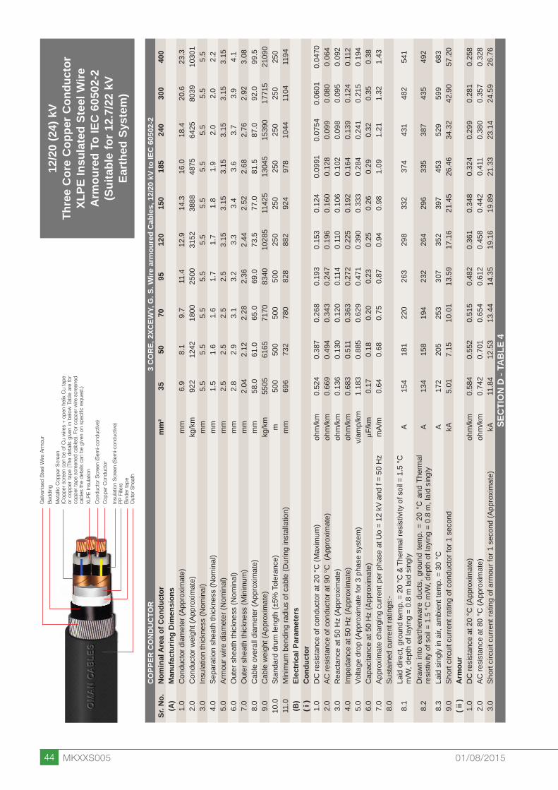
44 MKXXS005 01/08/2015
CO
PPER
CO
ND
UC
TOR
3 C
OR
E, 2
XCEW
Y, G
. S. W
ire a
rmou
red
Cab
les,
12/
20 k
V to
IEC
605
02-2
Sr. N
o.N
omin
al A
rea
of C
ondu
ctor
mm
²35
5070
9512
015
018
524
030
040
0(A
)M
anuf
actu
ring
Dim
ensi
ons
1.0
Con
duct
or d
iam
eter
(App
roxi
mat
e)m
m6.
98.
19.
711
.412
.914
.316
.018
.420
.623
.32.
0C
ondu
ctor
wei
ght (
Appr
oxim
ate)
kg/k
m92
212
4218
0025
0031
5238
8848
7564
2580
3910
301
3.0
Insu
latio
n th
ickn
ess
(Nom
inal
)m
m5.
55.
55.
55.
55.
55.
55.
55.
55.
55.
54.
0Se
para
tion
shea
th th
ickn
ess
(Nom
inal
)m
m1.
51.
61.
61.
71.
71.
81.
92.
02.
02.
25.
0Ar
mou
r wire
dia
met
er (N
omin
al)
mm
2.5
2.5
2.5
2.5
3.15
3.15
3.15
3.15
3.15
3.15
6.0
Out
er s
heat
h th
ickn
ess
(Nom
inal
)m
m2.
82.
93.
13.
23.
33.
43.
63.
73.
94.
17.
0O
uter
she
ath
thic
knes
s (M
inim
um)
mm
2.04
2.12
2.28
2.36
2.44
2.52
2.68
2.76
2.92
3.08
8.0
Cab
le o
vera
ll di
amet
er (A
ppro
xim
ate)
mm
58.0
61.0
65.0
69.0
73.5
77.0
81.5
87.0
92.0
99.5
9.0
Cab
le w
eigh
t (Ap
prox
imat
e)kg
/km
5505
6165
7170
8340
1028
511
425
1304
515
390
1771
521
090
10.0
Stan
dard
dru
m le
ngth
(±5%
Tol
eran
ce)
m50
050
050
050
025
025
025
025
025
025
011
.0M
inim
um b
endi
ng ra
dius
of c
able
(Dur
ing
inst
alla
tion)
mm
696
732
780
828
882
924
978
1044
1104
1194
(B)
Elec
tric
al P
aram
eter
s( i
)C
ondu
ctor
1.0
DC
resi
stan
ce o
f con
duct
or a
t 20
°C (M
axim
um)
ohm
/km
0.
524
0.38
70.
268
0.19
30.
153
0.12
40.
0991
0.07
540.
0601
0.04
702.
0AC
resi
stan
ce o
f con
duct
or a
t 90
°C (
Appr
oxim
ate)
ohm
/km
0.
669
0.49
40.
343
0.24
70.
196
0.16
00.
128
0.09
90.
080
0.06
43.
0R
eact
ance
at 5
0 H
z (A
ppro
xim
ate)
ohm
/km
0.
136
0.13
00.
120
0.11
40.
110
0.10
60.
102
0.09
80.
095
0.09
24.
0Im
peda
nce
at 5
0 H
z (A
ppro
xim
ate)
ohm
/km
0.
683
0.51
10.
363
0.27
20.
225
0.19
20.
164
0.13
90.
124
0.11
25.
0Vo
ltage
dro
p (A
ppro
xim
ate
for 3
pha
se s
yste
m)
v/am
p/km
1.18
30.
885
0.62
90.
471
0.39
00.
333
0.28
40.
241
0.21
50.
194
6.0
Cap
acita
nce
at 5
0 H
z (A
ppro
xim
ate)
mF/k
m0.
170.
180.
200.
230.
250.
260.
290.
320.
350.
387.
0Ap
prox
imat
e ch
argi
ng c
urre
nt p
er p
hase
at U
o =
12 k
V an
d f =
50
Hz
mA/
m0.
640.
680.
750.
870.
940.
981.
091.
211.
321.
438.
0Su
stai
ned
curre
nt ra
tings
:-
8.1
Laid
dire
ct, g
roun
d te
mp.
= 2
0 °C
& T
herm
al re
sist
ivity
of s
oil =
1.5
°C
m/W
, dep
th o
f lay
ing
= 0.
8 m
laid
sin
gly
A15
418
122
026
329
833
237
443
148
254
1
8.2
Dra
wn
into
ear
then
war
e du
cts,
gro
und
tem
p. =
20
°C a
nd T
herm
al
resi
stiv
ity o
f soi
l = 1
.5 °C
m/W
, dep
th o
f lay
ing
= 0.
8 m
, lai
d si
ngly
A13
415
819
423
226
429
633
538
743
549
2
8.3
Laid
sin
gly
in a
ir, a
mbi
ent t
emp.
= 3
0 °C
A
172
205
253
307
352
397
453
529
599
683
9.0
Shor
t circ
uit c
urre
nt ra
ting
of c
ondu
ctor
for 1
sec
ond
kA5.
017.
1510
.01
13.5
917
.16
21.4
526
.46
34.3
242
.90
57.2
0( i
i )A
rmou
r1.
0D
C re
sist
ance
at 2
0 °C
(App
roxi
mat
e)oh
m/k
m
0.58
40.
552
0.51
50.
482
0.36
10.
348
0.32
40.
299
0.28
10.
258
2.0
AC re
sist
ance
at 8
0 °C
(App
roxi
mat
e)oh
m/k
m
0.74
20.
701
0.65
40.
612
0.45
80.
442
0.41
10.
380
0.35
70.
328
3.0
Shor
t circ
uit c
urre
nt ra
ting
of a
rmou
r for
1 s
econ
d (A
ppro
xim
ate)
kA11
.84
12.5
313
.44
14.3
519
.16
19.8
921
.33
23.1
424
.59
26.7
6SE
CTI
ON
D -
TAB
LE 4
12/2
0 (2
4) k
VTh
ree
Cor
e C
oppe
r Con
duct
orXL
PE In
sula
ted
Stee
l Wire
Arm
oure
d To
IEC
605
02-2
(Sui
tabl
e fo
r 12.
7/22
kV
Eart
hed
Syst
em)
Gal
vani
sed
Ste
el W
ire A
rmou
r
Bed
ding
Met
allic
Cop
per
Scr
een
(Cop
per
scre
en c
an b
e of
Cu
wire
s +
ope
n he
lix C
u ta
pe
or c
oppe
r ta
pe (
The
deta
ils g
iven
in b
elow
Tab
le a
re f
or
copp
er ta
pe s
cree
ned
cabl
es).
For c
oppe
r wire
scr
eene
d ca
bles
the
det
ails
can
be
give
n on
spe
cific
req
uest
.)Xl
PE
Insu
latio
n
Con
duct
or S
cree
n (S
emi-c
ondu
ctiv
e)
Cop
per
Con
duct
or
Insu
latio
n S
cree
n (S
emi-c
ondu
ctiv
e)P
P F
illers
Bin
der
tape
Out
er S
heat
h

45MKXXS005 01/08/2015
18/3
0 (3
6) k
VTh
ree
Cor
e C
oppe
r Con
duct
orXL
PE In
sula
ted
Stee
l Wire
Arm
oure
d To
IEC
605
02-2
(Sui
tabl
e fo
r 19/
33 k
VEa
rthe
d Sy
stem
)
Gal
vani
sed
Ste
el W
ire A
rmou
r
Bed
ding
Met
allic
Cop
per
Scr
een
(Cop
per
scre
en c
an b
e of
Cu
wire
s +
ope
n he
lix C
u ta
pe
or c
oppe
r ta
pe (
The
deta
ils g
iven
in b
elow
Tab
le a
re f
or
copp
er ta
pe s
cree
ned
cabl
es).
For c
oppe
r wire
scr
eene
d ca
bles
the
det
ails
can
be
give
n on
spe
cific
req
uest
.)Xl
PE
Insu
latio
n
Con
duct
or S
cree
n (S
emi-c
ondu
ctiv
e)
Cop
per
Con
duct
or
Insu
latio
n S
cree
n (S
emi-c
ondu
ctiv
e)P
P F
illers
Bin
der
tape
Out
er S
heat
h
CO
PPER
CO
ND
UC
TOR
3 C
OR
E, 2
XCEW
Y, G
. S. W
ire a
rmou
red
Cab
les,
18/
30 k
V to
IEC
605
02-2
Sr. N
o.N
omin
al A
rea
of C
ondu
ctor
mm
²50
7095
120
150
185
240
300
400
(A)
Man
ufac
turin
g D
imen
sion
s1.
0C
ondu
ctor
dia
met
er (A
ppro
xim
ate)
mm
8.1
9.7
11.4
12.9
14.3
16.0
18.4
20.6
23.3
2.0
Con
duct
or w
eigh
t (Ap
prox
imat
e)kg
/km
1242
1800
2500
3152
3888
4875
6425
8039
1030
13.
0In
sula
tion
thic
knes
s (N
omin
al)
mm
8.0
8.0
8.0
8.0
8.0
8.0
8.0
8.0
8.0
4.0
Sepa
ratio
n sh
eath
thic
knes
s (N
omin
al)
mm
1.8
1.8
1.9
2.0
2.0
2.1
2.2
2.3
2.4
5.0
Arm
our w
ire d
iam
eter
(Nom
inal
)m
m3.
153.
153.
153.
153.
153.
153.
153.
153.
156.
0O
uter
she
ath
thic
knes
s (N
omin
al)
mm
3.4
3.5
3.6
3.7
3.8
4.0
4.1
4.3
4.5
7.0
Out
er s
heat
h th
ickn
ess
(Min
imum
)m
m2.
522.
602.
682.
762.
843.
003.
083.
243.
408.
0C
able
ove
rall
diam
eter
(App
roxi
mat
e)m
m74
.578
.082
.586
.089
.093
.599
.010
4.0
111.
59.
0C
able
wei
ght (
Appr
oxim
ate)
kg/k
m86
9597
6511
105
1230
013
460
1516
017
550
2000
523
505
10.0
Stan
dard
dru
m le
ngth
(±5%
Tol
eran
ce)
m25
025
025
025
025
025
025
025
025
011
.0M
inim
um b
endi
ng ra
dius
of c
able
(Dur
ing
inst
alla
tion)
mm
894
936
990
1032
1068
1122
1188
1248
1338
(B)
Elec
tric
al P
aram
eter
s( i
)C
ondu
ctor
1.0
DC
resi
stan
ce o
f con
duct
or a
t 20
°C (M
axim
um)
ohm
/km
0.
387
0.26
80.
193
0.15
30.
124
0.09
910.
0754
0.06
010.
0470
2.0
AC re
sist
ance
of c
ondu
ctor
at 9
0 °C
(Ap
prox
imat
e)oh
m/k
m
0.49
40.
343
0.24
70.
196
0.16
00.
128
0.09
80.
079
0.06
33.
0R
eact
ance
at 5
0 H
z (A
ppro
xim
ate)
ohm
/km
0.
143
0.13
20.
125
0.12
00.
117
0.11
20.
107
0.10
30.
100
4.0
Impe
danc
e at
50
Hz
(App
roxi
mat
e)oh
m/k
m
0.51
40.
368
0.27
70.
230
0.19
80.
170
0.14
50.
130
0.11
85.
0Vo
ltage
dro
p (A
ppro
xim
ate
for 3
pha
se s
yste
m)
v/am
p/km
0.89
00.
637
0.48
00.
398
0.34
30.
294
0.25
10.
225
0.20
46.
0C
apac
itanc
e at
50
Hz
(App
roxi
mat
e)mF
/km
0.14
0.16
0.17
0.19
0.20
0.22
0.24
0.26
0.28
7.0
Appr
oxim
ate
char
ging
cur
rent
per
pha
se a
t Uo
= 18
kV
and
f = 5
0 H
zm
A/m
0.79
0.90
0.96
1.07
1.13
1.24
1.36
1.47
1.58
8.0
Sust
aine
d cu
rrent
ratin
gs:-
8.1
Laid
dire
ct, g
roun
d te
mp.
= 2
0 °C
& T
herm
al re
sist
ivity
of s
oil =
1.5
°C
m/W
, dep
th o
f lay
ing
= 0.
8 m
laid
sin
gly
A18
122
026
329
833
237
443
148
254
1
8.2
Dra
wn
into
ear
then
war
e du
cts,
gro
und
tem
p. =
20
°C a
nd T
herm
al
resi
stiv
ity o
f soi
l = 1
.5 °C
m/W
, dep
th o
f lay
ing
= 0.
8 m
, lai
d si
ngly
A15
819
423
226
429
633
538
743
549
2
8.3
Laid
sin
gly
in a
ir, a
mbi
ent t
emp.
= 3
0 °C
A
205
253
307
352
397
453
529
599
683
9.0
Shor
t circ
uit c
urre
nt ra
ting
of c
ondu
ctor
for 1
sec
ond
kA7.
1510
.01
13.5
917
.16
21.4
526
.46
34.3
242
.90
57.2
0( i
i )A
rmou
r1.
0D
C re
sist
ance
at 2
0 °C
(App
roxi
mat
e)oh
m/k
m
0.36
10.
342
0.31
90.
304
0.29
40.
277
0.25
80.
245
0.22
82.
0AC
resi
stan
ce a
t 80
°C (A
ppro
xim
ate)
ohm
/km
0.
458
0.43
40.
405
0.38
60.
373
0.35
20.
328
0.31
10.
290
3.0
Shor
t circ
uit c
urre
nt ra
ting
of a
rmou
r for
1 s
econ
d (A
ppro
xim
ate)
kA19
.16
20.2
521
.70
22.7
823
.50
24.9
526
.76
28.2
030
.37
SEC
TIO
N D
- TA
BLE
5

46 MKXXS005 01/08/2015
3.6/
6 (7
.2) k
VTh
ree
Cor
e A
lum
iniu
m C
ondu
ctor
XLPE
Insu
late
d St
eel W
ireA
rmou
red
To IE
C 6
0502
-2(S
uita
ble
for 3
.8/6
.6 k
VEa
rthe
d Sy
stem
)
Gal
vani
sed
Ste
el W
ire A
rmou
r
Bed
ding
Met
allic
Cop
per
Scr
een
(Cop
per
scre
en c
an b
e of
Cu
wire
s +
ope
n he
lix C
u ta
pe
or c
oppe
r ta
pe (
The
deta
ils g
iven
in b
elow
Tab
le a
re f
or
copp
er ta
pe s
cree
ned
cabl
es).
For c
oppe
r wire
scr
eene
d ca
bles
the
det
ails
can
be
give
n on
spe
cific
req
uest
.)Xl
PE
Insu
latio
n
Con
duct
or S
cree
n (S
emi-c
ondu
ctiv
e)
Alu
min
ium
Con
duct
or
Insu
latio
n S
cree
n (S
emi-c
ondu
ctiv
e)P
P F
illers
Bin
der
tape
Out
er S
heat
h
ALU
MIN
IUM
CO
ND
UC
TOR
3 C
OR
E, A
2XC
EWY,
G. S
. Wire
arm
oure
d C
able
s, 3
.6/6
kV
to IE
C 6
0502
-2Sr
. No.
Nom
inal
Are
a of
Con
duct
orm
m²
2535
5070
9512
015
018
524
030
040
0(A
)M
anuf
actu
ring
Dim
ensi
ons
1.0
Con
duct
or d
iam
eter
(App
roxi
mat
e)m
m5.
96.
98.
19.
711
.412
.914
.316
.018
.420
.623
.32.
0C
ondu
ctor
wei
ght (
Appr
oxim
ate)
kg/k
m20
328
038
155
376
496
511
8615
0019
6724
4531
263.
0In
sula
tion
thic
knes
s (N
omin
al)
mm
2.5
2.5
2.5
2.5
2.5
2.5
2.5
2.5
2.6
2.8
3.0
4.0
Sepa
ratio
n sh
eath
thic
knes
s (N
omin
al)
mm
1.2
1.2
1.3
1.4
1.4
1.5
1.5
1.6
1.7
1.8
2.0
5.0
Arm
our w
ire d
iam
eter
(Nom
inal
)m
m2.
02.
02.
52.
52.
52.
52.
52.
52.
53.
153.
156.
0O
uter
she
ath
thic
knes
s (N
omin
al)
mm
2.3
2.3
2.5
2.6
2.7
2.8
2.9
3.0
3.2
3.5
3.8
7.0
Out
er s
heat
h th
ickn
ess
(Min
imum
)m
m1.
641.
641.
801.
881.
962.
042.
122.
202.
362.
602.
848.
0C
able
ove
rall
diam
eter
(App
roxi
mat
e)m
m40
.042
.546
.550
.554
.057
.561
.065
.071
.079
.087
.59.
0C
able
wei
ght (
Appr
oxim
ate)
kg/k
m25
5027
9535
6541
0046
8052
2557
8565
1076
8598
3511
735
10.0
Stan
dard
dru
m le
ngth
(±5%
Tol
eran
ce)
m50
050
050
050
050
050
050
050
050
025
025
011
.0M
inim
um b
endi
ng ra
dius
of c
able
(Dur
ing
inst
alla
tion)
mm
480
510
558
606
648
690
732
780
852
948
1050
(B)
Elec
tric
al P
aram
eter
s( i
)C
ondu
ctor
1.0
DC
resi
stan
ce o
f con
duct
or a
t 20
°C (M
axim
um)
ohm
/km
1.
200.
868
0.64
10.
443
0.32
00.
253
0.20
60.
164
0.12
50.
100
0.07
782.
0AC
resi
stan
ce o
f con
duct
or a
t 90
°C (
Appr
oxim
ate)
ohm
/km
1.
541.
110.
823
0.56
90.
411
0.32
60.
266
0.21
20.
162
0.13
10.
103
3.0
Rea
ctan
ce a
t 50
Hz
(App
roxi
mat
e)oh
m/k
m
0.12
00.
114
0.10
90.
100
0.09
60.
093
0.09
10.
087
0.08
50.
084
0.08
24.
0Im
peda
nce
at 5
0 H
z (A
ppro
xim
ate)
ohm
/km
1.
541.
120.
830
0.57
80.
422
0.33
90.
281
0.22
90.
183
0.15
60.
132
5.0
Volta
ge d
rop
(App
roxi
mat
e fo
r 3 p
hase
sys
tem
)v/
amp/
km2.
667
1.94
01.
438
1.00
10.
731
0.58
70.
487
0.39
70.
317
0.27
00.
229
6.0
Cap
acita
nce
at 5
0 H
z (A
ppro
xim
ate)
mF/k
m0.
270.
290.
330.
380.
420.
470.
510.
550.
600.
620.
657.
0Ap
prox
imat
e ch
argi
ng c
urre
nt p
er p
hase
at U
o =
3.6
kV a
nd f
= 50
Hz
mA/
m0.
310.
330.
370.
430.
480.
530.
580.
620.
680.
700.
748.
0Su
stai
ned
curre
nt ra
tings
:-
8.1
Laid
dire
ct, g
roun
d te
mp.
= 2
0 °C
& T
herm
al re
sist
ivity
of s
oil =
1.5
°C
m/W
, dep
th o
f lay
ing
= 0.
8 m
laid
sin
gly
A10
011
914
017
120
423
225
929
333
838
043
2
8.2
Dra
wn
into
ear
then
war
e du
cts,
gro
und
tem
p. =
20
°C a
nd T
herm
al
resi
stiv
ity o
f soi
l = 1
.5 °C
m/W
, dep
th o
f lay
ing
= 0.
8 m
, lai
d si
ngly
A87
104
123
150
180
206
231
262
304
343
393
8.3
Laid
sin
gly
in a
ir, a
mbi
ent t
emp.
= 3
0 °C
A
111
133
159
196
238
274
309
354
415
472
545
9.0
Shor
t circ
uit c
urre
nt ra
ting
of c
ondu
ctor
for 1
sec
ond
kA2.
353.
294.
706.
588.
9311
.28
14.1
017
.39
22.5
628
.20
37.6
0( i
i )A
rmou
r1.
0D
C re
sist
ance
at 2
0 °C
(App
roxi
mat
e)oh
m/k
m
1.10
01.
030
0.77
90.
706
0.64
60.
595
0.55
20.
515
0.46
00.
336
0.29
92.
0AC
resi
stan
ce a
t 80
°C (A
ppro
xim
ate)
ohm
/km
1.
397
1.30
80.
989
0.89
70.
820
0.75
60.
701
0.65
40.
584
0.42
70.
380
3.0
Shor
t circ
uit c
urre
nt ra
ting
of a
rmou
r for
1 s
econ
d (A
ppro
xim
ate)
kA6.
276.
718.
889.
7910
.70
11.6
212
.53
13.4
415
.03
20.6
123
.14
SEC
TIO
N D
- TA
BLE
6

47MKXXS005 01/08/2015
6/10
(12)
kV
Thre
e C
ore
Alu
min
ium
Con
duct
orXL
PE In
sula
ted
Stee
l Wire
Arm
oure
d To
IEC
605
02-2
(Sui
tabl
e fo
r 6.3
5/11
kV
Eart
hed
Syst
em)
ALU
MIN
IUM
CO
ND
UC
TOR
3 C
OR
E, A
2XC
EWY,
G. S
. Wire
arm
oure
d C
able
s, 6
/10
kV to
IEC
605
02-2
Sr. N
o.N
omin
al A
rea
of C
ondu
ctor
mm
²25
3550
7095
120
150
185
240
300
400
(A)
Man
ufac
turin
g D
imen
sion
s1.
0C
ondu
ctor
dia
met
er (A
ppro
xim
ate)
mm
5.9
6.9
8.1
9.7
11.4
12.9
14.3
16.0
18.4
20.6
23.3
2.0
Con
duct
or w
eigh
t (Ap
prox
imat
e)kg
/km
203
280
381
553
764
965
1186
1500
1967
2445
3126
3.0
Insu
latio
n th
ickn
ess
(Nom
inal
)m
m3.
43.
43.
43.
43.
43.
43.
43.
43.
43.
43.
44.
0Se
para
tion
shea
th th
ickn
ess
(Nom
inal
)m
m1.
31.
31.
41.
41.
51.
61.
61.
71.
81.
92.
05.
0Ar
mou
r wire
dia
met
er (N
omin
al)
mm
2.5
2.5
2.5
2.5
2.5
2.5
2.5
2.5
3.15
3.15
3.15
6.0
Out
er s
heat
h th
ickn
ess
(Nom
inal
)m
m2.
42.
52.
62.
72.
93.
03.
13.
23.
43.
63.
87.
0O
uter
she
ath
thic
knes
s (M
inim
um)
mm
1.72
1.80
1.88
1.96
2.12
2.20
2.28
2.36
2.52
2.68
2.84
8.0
Cab
le o
vera
ll di
amet
er (A
ppro
xim
ate)
mm
45.5
48.0
51.0
54.5
58.5
62.0
65.0
69.5
76.5
82.0
89.0
9.0
Cab
le w
eigh
t (Ap
prox
imat
e)kg
/km
3335
3660
4060
4600
5220
5815
6355
7145
9160
1031
012
060
10.0
Stan
dard
dru
m le
ngth
(±5%
Tol
eran
ce)
m50
050
050
050
050
050
050
050
025
025
025
011
.0M
inim
um b
endi
ng ra
dius
of c
able
(Dur
ing
inst
alla
tion)
mm
546
576
612
654
702
744
780
834
918
984
1068
(B)
Elec
tric
al P
aram
eter
s( i
)C
ondu
ctor
1.0
DC
resi
stan
ce o
f con
duct
or a
t 20
°C (M
axim
um)
ohm
/km
1.
200.
868
0.64
10.
443
0.32
00.
253
0.20
60.
164
0.12
50.
100
0.07
782.
0AC
resi
stan
ce o
f con
duct
or a
t 90
°C (
Appr
oxim
ate)
ohm
/km
1.
541.
110.
823
0.56
90.
411
0.32
60.
265
0.21
20.
162
0.13
10.
103
3.0
Rea
ctan
ce a
t 50
Hz
(App
roxi
mat
e)oh
m/k
m
0.12
70.
121
0.11
60.
107
0.10
20.
098
0.09
60.
092
0.08
90.
086
0.08
44.
0Im
peda
nce
at 5
0 H
z (A
ppro
xim
ate)
ohm
/km
1.
551.
120.
831
0.57
90.
423
0.34
00.
282
0.23
10.
185
0.15
70.
133
5.0
Volta
ge d
rop
(App
roxi
mat
e fo
r 3 p
hase
sys
tem
)v/
amp/
km2.
685
1.94
01.
439
1.00
30.
733
0.58
90.
488
0.40
00.
320
0.27
20.
230
6.0
Cap
acita
nce
at 5
0 H
z (A
ppro
xim
ate)
mF/k
m0.
210.
230.
260.
290.
330.
360.
390.
420.
480.
520.
587.
0Ap
prox
imat
e ch
argi
ng c
urre
nt p
er p
hase
at U
o =
6 kV
and
f =
50 H
zm
A/m
0.40
0.43
0.49
0.55
0.62
0.68
0.74
0.79
0.90
0.98
1.09
8.0
Sust
aine
d cu
rrent
ratin
gs:-
8.1
Laid
dire
ct, g
roun
d te
mp.
= 2
0 °C
& T
herm
al re
sist
ivity
of s
oil =
1.5
°C
m/W
, dep
th o
f lay
ing
= 0.
8 m
laid
sin
gly
A10
011
914
017
120
423
225
929
333
838
043
2
8.2
Dra
wn
into
ear
then
war
e du
cts,
gro
und
tem
p. =
20
°C a
nd T
herm
al
resi
stiv
ity o
f soi
l = 1
.5 °C
m/W
, dep
th o
f lay
ing
= 0.
8 m
, lai
d si
ngly
A87
104
123
150
180
206
231
262
304
343
393
8.3
Laid
sin
gly
in a
ir, a
mbi
ent t
emp.
= 3
0 °C
A
111
133
159
196
238
274
309
354
415
472
545
9.0
Shor
t circ
uit c
urre
nt ra
ting
of c
ondu
ctor
for 1
sec
ond
kA2.
353.
294.
706.
588.
9311
.28
14.1
017
.39
22.5
628
.20
37.6
0( i
i )A
rmou
r1.
0D
C re
sist
ance
at 2
0 °C
(App
roxi
mat
e)oh
m/k
m
0.79
90.
741
0.69
00.
633
0.58
40.
542
0.51
50.
474
0.34
80.
324
0.29
02.
0AC
resi
stan
ce a
t 80
°C (A
ppro
xim
ate)
ohm
/km
1.
015
0.94
10.
876
0.80
40.
742
0.68
80.
654
0.60
20.
442
0.41
10.
368
3.0
Shor
t circ
uit c
urre
nt ra
ting
of a
rmou
r for
1 s
econ
d (A
ppro
xim
ate)
kA8.
669.
3410
.02
10.9
311
.84
12.7
513
.44
14.5
819
.89
21.3
323
.87
SEC
TIO
N D
- TA
BLE
7
Gal
vani
sed
Ste
el W
ire A
rmou
r
Bed
ding
Met
allic
Cop
per
Scr
een
(Cop
per
scre
en c
an b
e of
Cu
wire
s +
ope
n he
lix C
u ta
pe
or c
oppe
r ta
pe (
The
deta
ils g
iven
in b
elow
Tab
le a
re f
or
copp
er ta
pe s
cree
ned
cabl
es).
For c
oppe
r wire
scr
eene
d ca
bles
the
det
ails
can
be
give
n on
spe
cific
req
uest
.)Xl
PE
Insu
latio
n
Con
duct
or S
cree
n (S
emi-c
ondu
ctiv
e)
Alu
min
ium
Con
duct
or
Insu
latio
n S
cree
n (S
emi-c
ondu
ctiv
e)P
P F
illers
Bin
der
tape
Out
er S
heat
h

48 MKXXS005 01/08/2015
ALU
MIN
IUM
CO
ND
UC
TOR
3 C
OR
E, A
2XC
EWY,
G. S
. Wire
arm
oure
d C
able
s, 8
.7/1
5 kV
to IE
C 6
0502
-2Sr
. No.
Nom
inal
Are
a of
Con
duct
orm
m²
2535
5070
9512
015
018
524
030
040
0(A
)M
anuf
actu
ring
Dim
ensi
ons
1.0
Con
duct
or d
iam
eter
(App
roxi
mat
e)m
m5.
96.
98.
19.
711
.412
.914
.316
.018
.420
.623
.32.
0C
ondu
ctor
wei
ght (
Appr
oxim
ate)
kg/k
m20
328
038
155
376
496
511
8615
0019
6724
4531
263.
0In
sula
tion
thic
knes
s (N
omin
al)
mm
4.5
4.5
4.5
4.5
4.5
4.5
4.5
4.5
4.5
4.5
4.5
4.0
Sepa
ratio
n sh
eath
thic
knes
s (N
omin
al)
mm
1.4
1.4
1.5
1.5
1.6
1.7
1.7
1.8
1.9
2.0
2.1
5.0
Arm
our w
ire d
iam
eter
(Nom
inal
)m
m2.
52.
52.
52.
52.
52.
52.
53.
153.
153.
153.
156.
0O
uter
she
ath
thic
knes
s (N
omin
al)
mm
2.6
2.7
2.8
2.9
3.0
3.1
3.2
3.4
3.6
3.7
4.0
7.0
Out
er s
heat
h th
ickn
ess
(Min
imum
)m
m1.
881.
962.
042.
122.
202.
282.
362.
522.
682.
763.
008.
0C
able
ove
rall
diam
eter
(App
roxi
mat
e)m
m51
.053
.056
.059
.563
.567
.570
.576
.082
.087
.094
.59.
0C
able
wei
ght (
Appr
oxim
ate)
kg/k
m39
4542
5046
4552
1059
0065
2070
8087
5510
015
1123
013
010
10.0
Stan
dard
dru
m le
ngth
(±5%
Tol
eran
ce)
m50
050
050
050
050
050
050
025
025
025
025
011
.0M
inim
um b
endi
ng ra
dius
of c
able
(Dur
ing
inst
alla
tion)
mm
612
636
672
714
762
810
846
912
984
1044
1134
(B)
Elec
tric
al P
aram
eter
s( i
)C
ondu
ctor
1.0
DC
resi
stan
ce o
f con
duct
or a
t 20
°C (M
axim
um)
ohm
/km
1.
200.
868
0.64
10.
443
0.32
00.
253
0.20
60.
164
0.12
50.
100
0.07
782.
0AC
resi
stan
ce o
f con
duct
or a
t 90
°C (
Appr
oxim
ate)
ohm
/km
1.
541.
110.
823
0.56
90.
411
0.32
50.
265
0.21
20.
162
0.13
00.
103
3.0
Rea
ctan
ce a
t 50
Hz
(App
roxi
mat
e)oh
m/k
m
0.13
60.
129
0.12
30.
114
0.10
80.
104
0.10
10.
097
0.09
30.
091
0.08
84.
0Im
peda
nce
at 5
0 H
z (A
ppro
xim
ate)
ohm
/km
1.
551.
120.
832
0.58
00.
425
0.34
10.
284
0.23
30.
187
0.15
90.
135
5.0
Volta
ge d
rop
(App
roxi
mat
e fo
r 3 p
hase
sys
tem
)v/
amp/
km2.
685
1.94
01.
441
1.00
50.
736
0.59
10.
492
0.40
40.
324
0.27
50.
234
6.0
Cap
acita
nce
at 5
0 H
z (A
ppro
xim
ate)
mF/k
m0.
170.
190.
210.
240.
260.
290.
310.
340.
370.
410.
467.
0Ap
prox
imat
e ch
argi
ng c
urre
nt p
er p
hase
at U
o =
8.7
kV a
nd f
= 50
Hz
mA/
m0.
460.
520.
570.
660.
710.
790.
850.
931.
011.
121.
268.
0Su
stai
ned
curre
nt ra
tings
:-
8.1
Laid
dire
ct, g
roun
d te
mp.
= 2
0 °C
& T
herm
al re
sist
ivity
of s
oil =
1.5
°C
m/W
, dep
th o
f lay
ing
= 0.
8 m
laid
sin
gly
A10
011
914
017
120
423
225
929
333
838
043
2
8.2
Dra
wn
into
ear
then
war
e du
cts,
gro
und
tem
p. =
20
°C a
nd T
herm
al
resi
stiv
ity o
f soi
l = 1
.5 °C
m/W
, dep
th o
f lay
ing
= 0.
8 m
, lai
d si
ngly
A87
104
123
150
180
206
231
262
304
343
393
8.3
Laid
sin
gly
in a
ir, a
mbi
ent t
emp.
= 3
0 °C
A
111
133
159
196
238
274
309
354
415
472
545
9.0
Shor
t circ
uit c
urre
nt ra
ting
of c
ondu
ctor
for 1
sec
ond
kA2.
353.
294.
706.
588.
9311
.28
14.1
017
.39
22.5
628
.20
37.6
0( i
i )A
rmou
r1.
0D
C re
sist
ance
at 2
0 °C
(App
roxi
mat
e)oh
m/k
m
0.69
00.
660
0.62
00.
573
0.52
30.
490
0.46
70.
354
0.32
40.
299
0.27
32.
0AC
resi
stan
ce a
t 80
°C (A
ppro
xim
ate)
ohm
/km
0.
876
0.83
80.
787
0.72
80.
664
0.62
20.
593
0.45
00.
411
0.38
00.
347
3.0
Shor
t circ
uit c
urre
nt ra
ting
of a
rmou
r for
1 s
econ
d (A
ppro
xim
ate)
kA10
.02
10.4
811
.16
12.0
713
.21
14.1
214
.80
19.5
321
.33
23.1
425
.31
SEC
TIO
N D
- TA
BLE
8
8.7/
15 (1
7.5)
kV
Thre
e C
ore
Alu
min
ium
Con
duct
orXL
PE In
sula
ted
Stee
l Wire
Arm
oure
d To
IEC
605
02-2
(Sui
tabl
e fo
r 8.7
/15
kVEa
rthe
d Sy
stem
)
Gal
vani
sed
Ste
el W
ire A
rmou
r
Bed
ding
Met
allic
Cop
per
Scr
een
(Cop
per
scre
en c
an b
e of
Cu
wire
s +
ope
n he
lix C
u ta
pe
or c
oppe
r ta
pe (
The
deta
ils g
iven
in b
elow
Tab
le a
re f
or
copp
er ta
pe s
cree
ned
cabl
es).
For c
oppe
r wire
scr
eene
d ca
bles
the
det
ails
can
be
give
n on
spe
cific
req
uest
.)Xl
PE
Insu
latio
n
Con
duct
or S
cree
n (S
emi-c
ondu
ctiv
e)
Alu
min
ium
Con
duct
or
Insu
latio
n S
cree
n (S
emi-c
ondu
ctiv
e)P
P F
illers
Bin
der
tape
Out
er S
heat
h

49MKXXS005 01/08/2015
ALU
MIN
IUM
CO
ND
UC
TOR
3 C
OR
E, A
2XC
EWY,
G. S
. Wire
arm
oure
d C
able
s, 1
2/20
kV
to IE
C 6
0502
-2Sr
. No.
Nom
inal
Are
a of
Con
duct
orm
m²
3550
7095
120
150
185
240
300
400
(A)
Man
ufac
turin
g D
imen
sion
s1.
0C
ondu
ctor
dia
met
er (A
ppro
xim
ate)
mm
6.9
8.1
9.7
11.4
12.9
14.3
16.0
18.4
20.6
23.3
2.0
Con
duct
or w
eigh
t (Ap
prox
imat
e)kg
/km
280
381
553
764
965
1186
1500
1967
2445
3126
3.0
Insu
latio
n th
ickn
ess
(Nom
inal
)m
m5.
55.
55.
55.
55.
55.
55.
55.
55.
55.
54.
0Se
para
tion
shea
th th
ickn
ess
(Nom
inal
)m
m1.
51.
61.
61.
71.
71.
81.
92.
02.
02.
25.
0Ar
mou
r wire
dia
met
er (N
omin
al)
mm
2.5
2.5
2.5
2.5
3.15
3.15
3.15
3.15
3.15
3.15
6.0
Out
er s
heat
h th
ickn
ess
(Nom
inal
)m
m2.
82.
93.
13.
23.
33.
43.
63.
73.
94.
17.
0O
uter
she
ath
thic
knes
s (M
inim
um)
mm
2.04
2.12
2.28
2.36
2.44
2.52
2.68
2.76
2.92
3.08
8.0
Cab
le o
vera
ll di
amet
er (A
ppro
xim
ate)
mm
58.0
61.0
65.0
69.0
73.5
77.0
81.5
87.0
92.0
99.5
9.0
Cab
le w
eigh
t (Ap
prox
imat
e)kg
/km
4865
5305
5925
6605
8100
8725
9670
1093
512
125
1391
510
.0St
anda
rd d
rum
leng
th (±
5% T
oler
ance
)m
500
500
500
500
250
250
250
250
250
250
11.0
Min
imum
ben
ding
radi
us o
f cab
le (D
urin
g in
stal
latio
n)m
m69
673
278
082
888
292
497
810
4411
0411
94(B
)El
ectr
ical
Par
amet
ers
( i )
Con
duct
or1.
0D
C re
sist
ance
of c
ondu
ctor
at 2
0 °C
(Max
imum
)oh
m/k
m
0.86
80.
641
0.44
30.
320
0.25
30.
206
0.16
40.
125
0.10
00.
0778
2.0
AC re
sist
ance
of c
ondu
ctor
at 9
0 °C
(Ap
prox
imat
e)oh
m/k
m
1.11
0.82
30.
569
0.41
10.
325
0.26
50.
212
0.16
20.
130
0.10
23.
0R
eact
ance
at 5
0 H
z (A
ppro
xim
ate)
ohm
/km
0.
136
0.13
00.
120
0.11
40.
110
0.10
60.
102
0.09
80.
095
0.09
24.
0Im
peda
nce
at 5
0 H
z (A
ppro
xim
ate)
ohm
/km
1.
120.
833
0.58
20.
427
0.34
30.
285
0.23
50.
189
0.16
10.
137
5.0
Volta
ge d
rop
(App
roxi
mat
e fo
r 3 p
hase
sys
tem
)v/
amp/
km1.
940
1.44
31.
008
0.74
00.
594
0.49
40.
407
0.32
70.
279
0.23
76.
0C
apac
itanc
e at
50
Hz
(App
roxi
mat
e)mF
/km
0.17
0.18
0.20
0.23
0.25
0.26
0.29
0.32
0.35
0.38
7.0
Appr
oxim
ate
char
ging
cur
rent
per
pha
se a
t Uo
= 12
kV
and
f = 5
0 H
zm
A/m
0.64
0.68
0.75
0.87
0.94
0.98
1.09
1.21
1.32
1.43
8.0
Sust
aine
d cu
rrent
ratin
gs:-
8.1
Laid
dire
ct, g
roun
d te
mp.
= 2
0 °C
& T
herm
al re
sist
ivity
of s
oil =
1.5
°C
m/W
, dep
th o
f lay
ing
= 0.
8 m
laid
sin
gly
A11
914
017
120
423
225
929
333
838
043
2
8.2
Dra
wn
into
ear
then
war
e du
cts,
gro
und
tem
p. =
20
°C a
nd T
herm
al
resi
stiv
ity o
f soi
l = 1
.5 °C
m/W
, dep
th o
f lay
ing
= 0.
8 m
, lai
d si
ngly
A10
412
315
018
020
623
126
230
434
339
3
8.3
Laid
sin
gly
in a
ir, a
mbi
ent t
emp.
= 3
0 °C
A
133
159
196
238
274
309
354
415
472
545
9.0
Shor
t circ
uit c
urre
nt ra
ting
of c
ondu
ctor
for 1
sec
ond
kA3.
294.
706.
588.
9311
.28
14.1
017
.39
22.5
628
.20
37.6
0( i
i )A
rmou
r1.
0D
C re
sist
ance
at 2
0 °C
(App
roxi
mat
e)oh
m/k
m
0.58
40.
552
0.51
50.
482
0.36
10.
348
0.32
40.
299
0.28
10.
258
2.0
AC re
sist
ance
at 8
0 °C
(App
roxi
mat
e)oh
m/k
m
0.74
20.
701
0.65
40.
612
0.45
80.
442
0.41
10.
380
0.35
70.
328
3.0
Shor
t circ
uit c
urre
nt ra
ting
of a
rmou
r for
1 s
econ
d (A
ppro
xim
ate)
kA11
.84
12.5
313
.44
14.3
519
.16
19.8
921
.33
23.1
424
.59
26.7
6SE
CTI
ON
D -
TAB
LE 9
12/2
0 (2
4) k
VTh
ree
Cor
e A
lum
iniu
m C
ondu
ctor
XLPE
Insu
late
d St
eel W
ireA
rmou
red
To IE
C 6
0502
-2(S
uita
ble
for 1
2.7/
22 k
VEa
rthe
d Sy
stem
)
Gal
vani
sed
Ste
el W
ire A
rmou
r
Bed
ding
Met
allic
Cop
per
Scr
een
(Cop
per
scre
en c
an b
e of
Cu
wire
s +
ope
n he
lix C
u ta
pe
or c
oppe
r ta
pe (
The
deta
ils g
iven
in b
elow
Tab
le a
re f
or
copp
er ta
pe s
cree
ned
cabl
es).
For c
oppe
r wire
scr
eene
d ca
bles
the
det
ails
can
be
give
n on
spe
cific
req
uest
.)Xl
PE
Insu
latio
n
Con
duct
or S
cree
n (S
emi-c
ondu
ctiv
e)
Alu
min
ium
Con
duct
or
Insu
latio
n S
cree
n (S
emi-c
ondu
ctiv
e)P
P F
illers
Bin
der
tape
Out
er S
heat
h

50 MKXXS005 01/08/2015
18/3
0 (3
6) k
VTh
ree
Cor
e A
lum
iniu
m C
ondu
ctor
XLPE
Insu
late
d St
eel W
ireA
rmou
red
To IE
C 6
0502
-2(S
uita
ble
for 1
9/33
kV
Eart
hed
Syst
em)
Gal
vani
sed
Ste
el W
ire A
rmou
r
Bed
ding
Met
allic
Cop
per
Scr
een
(Cop
per
scre
en c
an b
e of
Cu
wire
s +
ope
n he
lix C
u ta
pe
or c
oppe
r ta
pe (
The
deta
ils g
iven
in b
elow
Tab
le a
re f
or
copp
er ta
pe s
cree
ned
cabl
es).
For c
oppe
r wire
scr
eene
d ca
bles
the
det
ails
can
be
give
n on
spe
cific
req
uest
.)Xl
PE
Insu
latio
n
Con
duct
or S
cree
n (S
emi-c
ondu
ctiv
e)
Alu
min
ium
Con
duct
or
Insu
latio
n S
cree
n (S
emi-c
ondu
ctiv
e)P
P F
illers
Bin
der
tape
Out
er S
heat
h
ALU
MIN
IUM
CO
ND
UC
TOR
3 C
OR
E, A
2XC
EWY,
G. S
. Wire
arm
oure
d C
able
s, 1
8/30
kV
to IE
C 6
0502
-2Sr
. No.
Nom
inal
Are
a of
Con
duct
orm
m²
5070
9512
015
018
524
030
040
0(A
)M
anuf
actu
ring
Dim
ensi
ons
1.0
Con
duct
or d
iam
eter
(App
roxi
mat
e)m
m8.
19.
711
.412
.914
.316
.018
.420
.623
.32.
0C
ondu
ctor
wei
ght (
Appr
oxim
ate)
kg/k
m38
155
376
496
511
8615
0019
6724
4531
263.
0In
sula
tion
thic
knes
s (N
omin
al)
mm
8.0
8.0
8.0
8.0
8.0
8.0
8.0
8.0
8.0
4.0
Sepa
ratio
n sh
eath
thic
knes
s (N
omin
al)
mm
1.8
1.8
1.9
2.0
2.0
2.1
2.2
2.3
2.4
5.0
Arm
our w
ire d
iam
eter
(Nom
inal
)m
m3.
153.
153.
153.
153.
153.
153.
153.
153.
156.
0O
uter
she
ath
thic
knes
s (N
omin
al)
mm
3.4
3.5
3.6
3.7
3.8
4.0
4.1
4.3
4.5
7.0
Out
er s
heat
h th
ickn
ess
(Min
imum
)m
m2.
522.
602.
682.
762.
843.
003.
083.
243.
408.
0C
able
ove
rall
diam
eter
(App
roxi
mat
e)m
m74
.578
.082
.586
.089
.093
.599
.010
4.0
111.
59.
0C
able
wei
ght (
Appr
oxim
ate)
kg/k
m78
3585
2093
7010
115
1076
011
780
1309
514
410
1632
510
.0St
anda
rd d
rum
leng
th (±
5% T
oler
ance
)m
250
250
250
250
250
250
250
250
250
11.0
Min
imum
ben
ding
radi
us o
f cab
le (D
urin
g in
stal
latio
n)m
m89
493
699
010
3210
6811
2211
8812
4813
38(B
)El
ectr
ical
Par
amet
ers
( i )
Con
duct
or1.
0D
C re
sist
ance
of c
ondu
ctor
at 2
0 °C
(Max
imum
)oh
m/k
m
0.64
10.
443
0.32
00.
253
0.20
60.
164
0.12
50.
100
0.07
782.
0AC
resi
stan
ce o
f con
duct
or a
t 90
°C (
Appr
oxim
ate)
ohm
/km
0.
823
0.56
90.
411
0.32
50.
265
0.21
20.
162
0.13
00.
102
3.0
Rea
ctan
ce a
t 50
Hz
(App
roxi
mat
e)oh
m/k
m
0.14
30.
132
0.12
50.
120
0.11
70.
112
0.10
70.
103
0.10
04.
0Im
peda
nce
at 5
0 H
z (A
ppro
xim
ate)
ohm
/km
0.
835
0.58
40.
430
0.34
60.
290
0.24
00.
194
0.16
60.
143
5.0
Volta
ge d
rop
(App
roxi
mat
e fo
r 3 p
hase
sys
tem
)v/
amp/
km1.
446
1.01
20.
745
0.59
90.
502
0.41
60.
336
0.28
80.
248
6.0
Cap
acita
nce
at 5
0 H
z (A
ppro
xim
ate)
mF/k
m0.
140.
160.
170.
190.
200.
220.
240.
260.
287.
0Ap
prox
imat
e ch
argi
ng c
urre
nt p
er p
hase
at U
o =
18 k
V an
d f =
50
Hz
mA/
m0.
790.
900.
961.
071.
131.
241.
361.
471.
588.
0Su
stai
ned
curre
nt ra
tings
:-
8.1
Laid
dire
ct, g
roun
d te
mp.
= 2
0 °C
& T
herm
al re
sist
ivity
of s
oil =
1.5
°C
m/W
, dep
th o
f lay
ing
= 0.
8 m
laid
sin
gly
A14
017
120
423
225
929
333
838
043
2
8.2
Dra
wn
into
ear
then
war
e du
cts,
gro
und
tem
p. =
20
°C a
nd T
herm
al
resi
stiv
ity o
f soi
l = 1
.5 °C
m/W
, dep
th o
f lay
ing
= 0.
8 m
, lai
d si
ngly
A12
315
018
020
623
126
230
434
339
3
8.3
Laid
sin
gly
in a
ir, a
mbi
ent t
emp.
= 3
0 °C
A
159
196
238
274
309
354
415
472
545
9.0
Shor
t circ
uit c
urre
nt ra
ting
of c
ondu
ctor
for 1
sec
ond
kA4.
706.
588.
9311
.28
14.1
017
.39
22.5
628
.20
37.6
0( i
i )A
rmou
r1.
0D
C re
sist
ance
at 2
0 °C
(App
roxi
mat
e)oh
m/k
m
0.36
10.
342
0.31
90.
304
0.29
40.
277
0.25
80.
245
0.22
82.
0AC
resi
stan
ce a
t 80
°C (A
ppro
xim
ate)
ohm
/km
0.
458
0.43
40.
405
0.38
60.
373
0.35
20.
328
0.31
10.
290
3.0
Shor
t circ
uit c
urre
nt ra
ting
of a
rmou
r for
1 s
econ
d (A
ppro
xim
ate)
kA19
.16
20.2
521
.70
22.7
823
.50
24.9
526
.76
28.2
030
.37
SEC
TIO
N D
- TA
BLE
10

51MKXXS005 01/08/2015
3.6/
6 (7
.2) k
VTh
ree
Cor
e C
oppe
r Con
duct
orXL
PE In
sula
ted
Dou
ble
Stee
l Tap
e A
rmou
red
To IE
C 6
0502
-2 (S
uita
ble
for 3
.8/6
.6 k
V Ea
rthe
d Sy
stem
)
Ste
el T
ape
Arm
our
Bin
der
Tape
Met
allic
Cop
per
Scr
een
(Cop
per
scre
en c
an b
e of
Cu
wire
s +
ope
n he
lix C
u ta
pe
or c
oppe
r ta
pe (
The
deta
ils g
iven
in b
elow
Tab
le a
re f
or
copp
er t
ape
scre
ened
cab
les)
. For
cop
per
wire
scr
eene
d ca
bles
the
det
ails
can
be
give
n on
spe
cific
req
uest
.)
XlP
E In
sula
tion
Con
duct
or S
cree
n (S
emi-c
ondu
ctiv
e)
Cop
per
Con
duct
orIn
sula
tion
Scr
een
(Sem
i-con
duct
ive)
PP
Fille
rB
eddi
ngO
uter
She
ath
CO
PPER
CO
ND
UC
TOR
3 C
OR
E, 2
XCET
gY, D
oubl
e St
eel T
ape
Arm
oure
d C
able
s, 3
.6/6
kV
to IE
C 6
0502
-2Sr
. No.
Nom
inal
Are
a of
Con
duct
orm
m²
2535
5070
9512
015
018
524
030
040
0(A
)M
anuf
actu
ring
Dim
ensi
ons
1.0
Con
duct
or d
iam
eter
(App
roxi
mat
e)m
m5.
96.
98.
19.
711
.412
.914
.316
.018
.420
.623
.32.
0C
ondu
ctor
wei
ght (
Appr
oxim
ate)
kg/k
m66
592
212
4218
0025
0031
5238
8848
7564
2580
3910
301
3.0
Insu
latio
n th
ickn
ess
(Nom
inal
)m
m2.
52.
52.
52.
52.
52.
52.
52.
52.
62.
83.
04.
0Se
para
tion
shea
th th
ickn
ess
(Nom
inal
)m
m1.
21.
21.
31.
41.
41.
51.
51.
61.
71.
82.
05.
0St
eel t
ape
thic
knes
s (N
omin
al)
mm
0.5
0.5
0.5
0.5
0.5
0.5
0.5
0.5
0.5
0.5
0.8
6.0
Out
er s
heat
h th
ickn
ess
(Nom
inal
)m
m2.
22.
32.
42.
52.
62.
72.
82.
93.
13.
33.
67.
0O
uter
she
ath
thic
knes
s (M
inim
um)
mm
1.56
1.64
1.72
1.80
1.88
1.96
2.04
2.12
2.28
2.44
2.68
8.0
Cab
le o
vera
ll di
amet
er (A
ppro
xim
ate)
mm
38.0
40.5
43.5
47.0
51.0
54.5
57.5
61.5
68.0
74.0
84.0
9.0
Cab
le w
eigh
t (Ap
prox
imat
e)kg
/km
2245
2645
3160
3975
4930
5845
6775
8065
1012
012
285
1624
010
.0St
anda
rd d
rum
leng
th (±
5% T
oler
ance
)m
1000
500
500
500
500
500
500
500
500
250
250
11.0
Min
imum
ben
ding
radi
us o
f cab
le (D
urin
g in
stal
latio
n)m
m57
060
865
370
576
581
886
392
310
2011
1012
60(B
)El
ectr
ical
Par
amet
ers
1.0
DC
resi
stan
ce o
f con
duct
or a
t 20
°C (M
axim
um)
ohm
/km
0.
727
0.52
40.
387
0.26
80.
193
0.15
30.
124
0.09
910.
0754
0.06
010.
0470
2.0
AC re
sist
ance
of c
ondu
ctor
at 9
0 °C
(Ap
prox
imat
e)oh
m/k
m
0.92
80.
669
0.49
40.
343
0.24
70.
197
0.16
00.
129
0.09
90.
080
0.06
53.
0R
eact
ance
at 5
0 H
z (A
ppro
xim
ate)
ohm
/km
0.
120
0.11
40.
109
0.10
00.
096
0.09
30.
091
0.08
70.
085
0.08
40.
082
4.0
Impe
danc
e at
50
Hz
(App
roxi
mat
e)oh
m/k
m
0.93
60.
679
0.50
60.
357
0.26
50.
218
0.18
40.
156
0.13
00.
116
0.10
55.
0Vo
ltage
dro
p (A
ppro
xim
ate
for 3
pha
se s
yste
m)
v/am
p/km
1.62
11.
176
0.87
60.
618
0.45
90.
378
0.31
90.
270
0.22
50.
201
0.18
26.
0C
apac
itanc
e at
50
Hz
(App
roxi
mat
e)mF
/km
0.27
0.29
0.33
0.38
0.42
0.47
0.51
0.55
0.60
0.62
0.65
7.0
Appr
oxim
ate
char
ging
cur
rent
per
pha
se a
t Uo
= 3.
6 kV
and
f= 5
0 H
zm
A/m
0.31
0.33
0.37
0.43
0.48
0.53
0.58
0.62
0.68
0.70
0.74
8.0
Sust
aine
d cu
rrent
ratin
gs:-
8.1
Laid
dire
ct, g
roun
d te
mp.
= 2
0 °C
& T
herm
al re
sist
ivity
of s
oil =
1.5
°C
m/W
, dep
th o
f lay
ing
= 0.
8 m
laid
sin
gly
A12
915
418
122
026
329
833
237
443
148
254
1
8.2
Dra
wn
into
ear
then
war
e du
cts,
gro
und
tem
p. =
20
°C a
nd T
herm
al
resi
stiv
ity o
f soi
l = 1
.5 °C
m/W
, dep
th o
f lay
ing
= 0.
8 m
, lai
d si
ngly
A11
213
415
819
423
226
429
633
538
743
549
2
8.3
Laid
sin
gly
in a
ir, a
mbi
ent t
emp.
= 3
0 °C
A
143
172
205
253
307
352
397
453
529
599
683
9.0
Shor
t circ
uit c
urre
nt ra
ting
of c
ondu
ctor
for 1
sec
ond
kA3.
585.
017.
1510
.01
13.5
917
.16
21.4
526
.46
34.3
242
.90
57.2
0SE
CTI
ON
E -
TAB
LE 1

52 MKXXS005 01/08/2015
CO
PPER
CO
ND
UC
TOR
3 C
OR
E, 2
XCET
gY, D
oubl
e St
eel T
ape
Arm
oure
d C
able
s, 6
/10
kV to
IEC
605
02-2
Sr. N
o.N
omin
al A
rea
of C
ondu
ctor
mm
²25
3550
7095
120
150
185
240
300
400
(A)
Man
ufac
turin
g D
imen
sion
s1.
0C
ondu
ctor
dia
met
er (A
ppro
xim
ate)
mm
5.9
6.9
8.1
9.7
11.4
12.9
14.3
16.0
18.4
20.6
23.3
2.0
Con
duct
or w
eigh
t (Ap
prox
imat
e)kg
/km
665
922
1242
1800
2500
3152
3888
4875
6425
8039
1030
13.
0In
sula
tion
thic
knes
s (N
omin
al)
mm
3.4
3.4
3.4
3.4
3.4
3.4
3.4
3.4
3.4
3.4
3.4
4.0
Sepa
ratio
n sh
eath
thic
knes
s (N
omin
al)
mm
1.3
1.3
1.4
1.4
1.5
1.6
1.6
1.7
1.8
1.9
2.0
5.0
Stee
l tap
e th
ickn
ess
(Nom
inal
)m
m0.
50.
50.
50.
50.
50.
50.
50.
50.
50.
50.
86.
0O
uter
she
ath
thic
knes
s (N
omin
al)
mm
2.3
2.4
2.5
2.6
2.7
2.9
3.0
3.1
3.3
3.4
3.7
7.0
Out
er s
heat
h th
ickn
ess
(Min
imum
)m
m1.
641.
721.
801.
881.
962.
122.
202.
282.
442.
522.
768.
0C
able
ove
rall
diam
eter
(App
roxi
mat
e)m
m42
.044
.547
.551
.055
.559
.062
.066
.072
.077
.086
.09.
0C
able
wei
ght (
Appr
oxim
ate)
kg/k
m25
6529
8035
1543
2553
3062
6572
4085
6010
605
1266
016
520
10.0
Stan
dard
dru
m le
ngth
(±5%
Tol
eran
ce)
m50
050
050
050
050
050
050
050
050
025
025
011
.0M
inim
um b
endi
ng ra
dius
of c
able
(Dur
ing
inst
alla
tion)
mm
630
668
713
765
833
885
930
990
1080
1155
1290
(B)
Elec
tric
al P
aram
eter
s1.
0D
C re
sist
ance
of c
ondu
ctor
at 2
0 °C
(Max
imum
)oh
m/k
m
0.72
70.
524
0.38
70.
268
0.19
30.
153
0.12
40.
0991
0.07
540.
0601
0.04
702.
0AC
resi
stan
ce o
f con
duct
or a
t 90
°C (
Appr
oxim
ate)
ohm
/km
0.
928
0.66
90.
494
0.34
30.
247
0.19
70.
160
0.12
90.
099
0.08
00.
065
3.0
Rea
ctan
ce a
t 50
Hz
(App
roxi
mat
e)oh
m/k
m
0.12
70.
121
0.11
60.
107
0.10
20.
098
0.09
60.
092
0.08
90.
086
0.08
44.
0Im
peda
nce
at 5
0 H
z (A
ppro
xim
ate)
ohm
/km
0.
937
0.68
00.
507
0.35
90.
267
0.22
00.
187
0.15
80.
133
0.11
70.
106
5.0
Volta
ge d
rop
(App
roxi
mat
e fo
r 3 p
hase
sys
tem
)v/
amp/
km1.
623
1.17
80.
878
0.62
20.
462
0.38
10.
324
0.27
40.
230
0.20
30.
184
6.0
Cap
acita
nce
at 5
0 H
z (A
ppro
xim
ate)
mF/k
m0.
210.
230.
260.
290.
330.
360.
390.
420.
480.
520.
587.
0Ap
prox
imat
e ch
argi
ng c
urre
nt p
er p
hase
at U
o =
6 kV
and
f= 5
0 H
zm
A/m
0.40
0.43
0.49
0.55
0.62
0.68
0.74
0.79
0.90
0.98
1.09
8.0
Sust
aine
d cu
rrent
ratin
gs:-
8.1
Laid
dire
ct, g
roun
d te
mp.
= 2
0 °C
& T
herm
al re
sist
ivity
of s
oil =
1.5
°C
m/W
, dep
th o
f lay
ing
= 0.
8 m
laid
sin
gly
A12
915
418
122
026
329
833
237
443
148
254
1
8.2
Dra
wn
into
ear
then
war
e du
cts,
gro
und
tem
p. =
20
°C a
nd T
herm
al re
-si
stiv
ity o
f soi
l = 1
.5 °C
m/W
, dep
th o
f lay
ing
= 0.
8 m
, lai
d si
ngly
A11
213
415
819
423
226
429
633
538
743
549
2
8.3
Laid
sin
gly
in a
ir, a
mbi
ent t
emp.
= 3
0 °C
A
143
172
205
253
307
352
397
453
529
599
683
9.0
Shor
t circ
uit c
urre
nt ra
ting
of c
ondu
ctor
for 1
sec
ond
kA3.
585.
017.
1510
.01
13.5
917
.16
21.4
526
.46
34.3
242
.90
57.2
0SE
CTI
ON
E -
TAB
LE 2
6/10
(12)
kV
Thre
e C
ore
Cop
per C
ondu
ctor
XLPE
Insu
late
d D
oubl
e St
eel T
ape
Arm
oure
dTo
IEC
605
02-2
(Sui
tabl
e fo
r 6.3
5/11
kV
Eart
hed
Syst
em)
Ste
el T
ape
Arm
our
Bin
der
Tape
Met
allic
Cop
per
Scr
een
(Cop
per
scre
en c
an b
e of
Cu
wire
s +
ope
n he
lix C
u ta
pe
or c
oppe
r ta
pe (
The
deta
ils g
iven
in b
elow
Tab
le a
re f
or
copp
er t
ape
scre
ened
cab
les)
. For
cop
per
wire
scr
eene
d ca
bles
the
det
ails
can
be
give
n on
spe
cific
req
uest
.)
XlP
E In
sula
tion
Con
duct
or S
cree
n (S
emi-c
ondu
ctiv
e)
Cop
per
Con
duct
orIn
sula
tion
Scr
een
(Sem
i-con
duct
ive)
PP
Fille
rB
eddi
ngO
uter
She
ath

53MKXXS005 01/08/2015
CO
PPER
CO
ND
UC
TOR
3 C
OR
E, 2
XCET
gY, D
oubl
e St
eel T
ape
Arm
oure
d C
able
s, 8
.7/1
5 kV
to IE
C 6
0502
-2Sr
. No.
Nom
inal
Are
a of
Con
duct
orm
m²
2535
5070
9512
015
018
524
030
040
0(A
)M
anuf
actu
ring
Dim
ensi
ons
1.0
Con
duct
or d
iam
eter
(App
roxi
mat
e)m
m5.
96.
98.
19.
711
.412
.914
.316
.018
.420
.623
.32.
0C
ondu
ctor
wei
ght (
Appr
oxim
ate)
kg/k
m66
592
212
4218
0025
0031
5238
8848
7564
2580
3910
301
3.0
Insu
latio
n th
ickn
ess
(Nom
inal
)m
m4.
54.
54.
54.
54.
54.
54.
54.
54.
54.
54.
54.
0Se
para
tion
shea
th th
ickn
ess
(Nom
inal
)m
m1.
41.
41.
51.
51.
61.
71.
71.
81.
92.
02.
15.
0St
eel t
ape
thic
knes
s (N
omin
al)
mm
0.5
0.5
0.5
0.5
0.5
0.5
0.5
0.5
0.5
0.8
0.8
6.0
Out
er s
heat
h th
ickn
ess
(Nom
inal
)m
m2.
52.
62.
72.
82.
93.
03.
13.
33.
43.
63.
97.
0O
uter
she
ath
thic
knes
s (M
inim
um)
mm
1.80
1.88
1.96
2.04
2.12
2.20
2.28
2.44
2.52
2.68
2.92
8.0
Cab
le o
vera
ll di
amet
er (A
ppro
xim
ate)
mm
47.5
50.0
53.0
56.5
60.5
64.0
67.0
71.5
77.0
83.5
91.0
9.0
Cab
le w
eigh
t (Ap
prox
imat
e)kg
/km
3000
3435
3990
4805
5835
6800
7795
9175
1123
014
185
1733
010
.0St
anda
rd d
rum
leng
th (±
5% T
oler
ance
)m
500
500
500
500
500
500
500
500
250
250
250
11.0
Min
imum
ben
ding
radi
us o
f cab
le (D
urin
g in
stal
latio
n)m
m71
375
079
584
890
896
010
0510
7311
5512
5313
65(B
)El
ectr
ical
Par
amet
ers
1.0
DC
resi
stan
ce o
f con
duct
or a
t 20
°C (M
axim
um)
ohm
/km
0.
727
0.52
40.
387
0.26
80.
193
0.15
30.
124
0.09
910.
0754
0.06
010.
0470
2.0
AC re
sist
ance
of c
ondu
ctor
at 9
0 °C
(Ap
prox
imat
e)oh
m/k
m
0.92
80.
669
0.49
40.
343
0.24
70.
197
0.16
00.
128
0.09
90.
080
0.06
43.
0R
eact
ance
at 5
0 H
z (A
ppro
xim
ate)
ohm
/km
0.
136
0.12
90.
123
0.11
40.
108
0.10
40.
101
0.09
70.
093
0.09
10.
088
4.0
Impe
danc
e at
50
Hz
(App
roxi
mat
e)oh
m/k
m
0.93
80.
681
0.50
90.
361
0.27
00.
223
0.18
90.
161
0.13
60.
121
0.10
95.
0Vo
ltage
dro
p (A
ppro
xim
ate
for 3
pha
se s
yste
m)
v/am
p/km
1.62
51.
180
0.88
20.
625
0.46
80.
386
0.32
70.
279
0.23
60.
210
0.18
96.
0C
apac
itanc
e at
50
Hz
(App
roxi
mat
e)mF
/km
0.17
0.19
0.21
0.24
0.26
0.29
0.31
0.34
0.37
0.41
0.46
7.0
Appr
oxim
ate
char
ging
cur
rent
per
pha
se a
t Uo
= 8.
7 kV
and
f= 5
0 H
zm
A/m
0.46
0.52
0.57
0.66
0.71
0.79
0.85
0.93
1.01
1.12
1.26
8.0
Sust
aine
d cu
rrent
ratin
gs:-
8.1
Laid
dire
ct, g
roun
d te
mp.
= 2
0 °C
& T
herm
al re
sist
ivity
of s
oil =
1.5
°C
m/W
, dep
th o
f lay
ing
= 0.
8 m
laid
sin
gly
A12
915
418
122
026
329
833
237
443
148
254
1
8.2
Dra
wn
into
ear
then
war
e du
cts,
gro
und
tem
p. =
20
°C a
nd T
herm
al
resi
stiv
ity o
f soi
l = 1
.5 °C
m/W
, dep
th o
f lay
ing
= 0.
8 m
, lai
d si
ngly
A11
213
415
819
423
226
429
633
538
743
549
2
8.3
Laid
sin
gly
in a
ir, a
mbi
ent t
emp.
= 3
0 °C
A
143
172
205
253
307
352
397
453
529
599
683
9.0
Shor
t circ
uit c
urre
nt ra
ting
of c
ondu
ctor
for 1
sec
ond
kA3.
585.
017.
1510
.01
13.5
917
.16
21.4
526
.46
34.3
242
.90
57.2
0SE
CTI
ON
E -
TAB
LE 3
8.7/
15 (1
7.5)
kV
Thre
e C
ore
Cop
per C
ondu
ctor
XLPE
Insu
late
d D
oubl
e St
eel T
ape
Arm
oure
dTo
IEC
605
02-2
(Sui
tabl
e fo
r 8.7
/15
kV E
arth
ed S
yste
m)
Ste
el T
ape
Arm
our
Bin
der
Tape
Met
allic
Cop
per
Scr
een
(Cop
per
scre
en c
an b
e of
Cu
wire
s +
ope
n he
lix C
u ta
pe
or c
oppe
r ta
pe (
The
deta
ils g
iven
in b
elow
Tab
le a
re f
or
copp
er t
ape
scre
ened
cab
les)
. For
cop
per
wire
scr
eene
d ca
bles
the
det
ails
can
be
give
n on
spe
cific
req
uest
.)
XlP
E In
sula
tion
Con
duct
or S
cree
n (S
emi-c
ondu
ctiv
e)
Cop
per
Con
duct
orIn
sula
tion
Scr
een
(Sem
i-con
duct
ive)
PP
Fille
rB
eddi
ngO
uter
She
ath

54 MKXXS005 01/08/2015
12/2
0 (2
4) k
VTh
ree
Cor
e C
oppe
r Con
duct
orXL
PE In
sula
ted
Dou
ble
Stee
l Tap
e A
rmou
red
To IE
C 6
0502
-2 (S
uita
ble
for 1
2.7/
22 k
V Ea
rthe
d Sy
stem
)
CO
PPER
CO
ND
UC
TOR
3 C
OR
E, 2
XCET
gY, D
oubl
e St
eel T
ape
Arm
oure
d C
able
s, 1
2/20
kV
to IE
C 6
0502
-2Sr
. No.
Nom
inal
Are
a of
Con
duct
orm
m²
3550
7095
120
150
185
240
300
400
(A)
Man
ufac
turin
g D
imen
sion
s1.
0C
ondu
ctor
dia
met
er (A
ppro
xim
ate)
mm
6.9
8.1
9.7
11.4
12.9
14.3
16.0
18.4
20.6
23.3
2.0
Con
duct
or w
eigh
t (Ap
prox
imat
e)kg
/km
922
1242
1800
2500
3152
3888
4875
6425
8039
1030
13.
0In
sula
tion
thic
knes
s (N
omin
al)
mm
5.5
5.5
5.5
5.5
5.5
5.5
5.5
5.5
5.5
5.5
4.0
Sepa
ratio
n sh
eath
thic
knes
s (N
omin
al)
mm
1.5
1.6
1.6
1.7
1.7
1.8
1.9
2.0
2.0
2.2
5.0
Stee
l tap
e th
ickn
ess
(Nom
inal
)m
m0.
50.
50.
50.
50.
50.
50.
50.
80.
80.
86.
0O
uter
she
ath
thic
knes
s (N
omin
al)
mm
2.7
2.8
2.9
3.1
3.2
3.3
3.4
3.6
3.8
4.0
7.0
Out
er s
heat
h th
ickn
ess
(Min
imum
)m
m1.
962.
042.
122.
282.
362.
442.
522.
682.
843.
008.
0C
able
ove
rall
diam
eter
(App
roxi
mat
e)m
m55
.058
.061
.566
.069
.072
.576
.583
.589
.096
.59.
0C
able
wei
ght (
Appr
oxim
ate)
kg/k
m39
0544
6053
2064
1073
6584
2098
0012
755
1493
518
140
10.0
Stan
dard
dru
m le
ngth
(±5%
Tol
eran
ce)
m50
050
050
050
050
050
025
025
025
025
011
.0M
inim
um b
endi
ng ra
dius
of c
able
(Dur
ing
inst
alla
tion)
mm
825
870
923
990
1035
1088
1148
1253
1335
1448
(B)
Elec
tric
al P
aram
eter
s1.
0D
C re
sist
ance
of c
ondu
ctor
at 2
0 °C
(Max
imum
)oh
m/k
m
0.52
40.
387
0.26
80.
193
0.15
30.
124
0.09
910.
0754
0.06
010.
0470
2.0
AC re
sist
ance
of c
ondu
ctor
at 9
0 °C
(Ap
prox
imat
e)oh
m/k
m
0.66
90.
494
0.34
30.
247
0.19
60.
160
0.12
80.
099
0.08
00.
064
3.0
Rea
ctan
ce a
t 50
Hz
(App
roxi
mat
e)oh
m/k
m
0.13
60.
130
0.12
00.
114
0.11
00.
106
0.10
20.
098
0.09
50.
092
4.0
Impe
danc
e at
50
Hz
(App
roxi
mat
e)oh
m/k
m
0.68
30.
511
0.36
30.
272
0.22
50.
192
0.16
40.
139
0.12
40.
112
5.0
Volta
ge d
rop
(App
roxi
mat
e fo
r 3 p
hase
sys
tem
)v/
amp/
km1.
183
0.88
50.
629
0.47
10.
390
0.33
30.
284
0.24
10.
215
0.19
46.
0C
apac
itanc
e at
50
Hz
(App
roxi
mat
e)mF
/km
0.17
0.18
0.20
0.23
0.25
0.26
0.29
0.32
0.35
0.38
7.0
Appr
oxim
ate
char
ging
cur
rent
per
pha
se a
t Uo
= 12
kV
and
f= 5
0 H
zm
A/m
0.64
0.68
0.75
0.87
0.94
0.98
1.09
1.21
1.32
1.43
8.0
Sust
aine
d cu
rrent
ratin
gs:-
8.1
Laid
dire
ct, g
roun
d te
mp.
= 2
0 °C
& T
herm
al re
sist
ivity
of s
oil =
1.5
°C
m/W
, dep
th o
f lay
ing
= 0.
8 m
laid
sin
gly
A15
418
122
026
329
833
237
443
148
254
1
8.2
Dra
wn
into
ear
then
war
e du
cts,
gro
und
tem
p. =
20
°C a
nd T
herm
al
resi
stiv
ity o
f soi
l = 1
.5 °C
m/W
, dep
th o
f lay
ing
= 0.
8 m
, lai
d si
ngly
A13
415
819
423
226
429
633
538
743
549
2
8.3
Laid
sin
gly
in a
ir, a
mbi
ent t
emp.
= 3
0 °C
A
172
205
253
307
352
397
453
529
599
683
9.0
Shor
t circ
uit c
urre
nt ra
ting
of c
ondu
ctor
for 1
sec
ond
kA5.
017.
1510
.01
13.5
917
.16
21.4
526
.46
34.3
242
.90
57.2
0SE
CTI
ON
E -
TAB
LE 4
Ste
el T
ape
Arm
our
Bin
der
Tape
Met
allic
Cop
per
Scr
een
(Cop
per
scre
en c
an b
e of
Cu
wire
s +
ope
n he
lix C
u ta
pe
or c
oppe
r ta
pe (
The
deta
ils g
iven
in b
elow
Tab
le a
re f
or
copp
er t
ape
scre
ened
cab
les)
. For
cop
per
wire
scr
eene
d ca
bles
the
det
ails
can
be
give
n on
spe
cific
req
uest
.)
XlP
E In
sula
tion
Con
duct
or S
cree
n (S
emi-c
ondu
ctiv
e)
Cop
per
Con
duct
orIn
sula
tion
Scr
een
(Sem
i-con
duct
ive)
PP
Fille
rB
eddi
ngO
uter
She
ath

55MKXXS005 01/08/2015
18/3
0 (3
6) k
VTh
ree
Cor
e C
oppe
r Con
duct
orXL
PE In
sula
ted
Dou
ble
Stee
l Tap
e A
rmou
red
To IE
C 6
0502
-2 (S
uita
ble
for 1
9/33
kV
Eart
hed
Syst
em)
Ste
el T
ape
Arm
our
Bin
der
Tape
Met
allic
Cop
per
Scr
een
(Cop
per
scre
en c
an b
e of
Cu
wire
s +
ope
n he
lix C
u ta
pe
or c
oppe
r ta
pe (
The
deta
ils g
iven
in b
elow
Tab
le a
re f
or
copp
er t
ape
scre
ened
cab
les)
. For
cop
per
wire
scr
eene
d ca
bles
the
det
ails
can
be
give
n on
spe
cific
req
uest
.)
XlP
E In
sula
tion
Con
duct
or S
cree
n (S
emi-c
ondu
ctiv
e)
Cop
per
Con
duct
orIn
sula
tion
Scr
een
(Sem
i-con
duct
ive)
PP
Fille
rB
eddi
ngO
uter
She
ath
CO
PPER
CO
ND
UC
TOR
3 C
OR
E, 2
XCET
gY, D
oubl
e St
eel T
ape
Arm
oure
d C
able
s, 1
8/30
kV
to IE
C 6
0502
-2Sr
. No.
Nom
inal
Are
a of
Con
duct
orm
m²
5070
9512
015
018
524
030
040
0(A
)M
anuf
actu
ring
Dim
ensi
ons
1.0
Con
duct
or d
iam
eter
(App
roxi
mat
e)m
m8.
19.
711
.412
.914
.316
.018
.420
.623
.32.
0C
ondu
ctor
wei
ght (
Appr
oxim
ate)
kg/k
m12
4218
0025
0031
5238
8848
7564
2580
3910
301
3.0
Insu
latio
n th
ickn
ess
(Nom
inal
)m
m8.
08.
08.
08.
08.
08.
08.
08.
08.
04.
0Se
para
tion
shea
th th
ickn
ess
(Nom
inal
)m
m1.
81.
81.
92.
02.
02.
12.
22.
32.
45.
0St
eel t
ape
thic
knes
s (N
omin
al)
mm
0.50
0.50
0.50
0.80
0.80
0.80
0.80
0.80
0.80
6.0
Out
er s
heat
h th
ickn
ess
(Nom
inal
)m
m3.
23.
33.
53.
63.
73.
94.
04.
24.
47.
0O
uter
she
ath
thic
knes
s (M
inim
um)
mm
2.36
2.44
2.60
2.68
2.76
2.92
3.00
3.16
3.32
8.0
Cab
le o
vera
ll di
amet
er (A
ppro
xim
ate)
mm
70.0
73.5
78.0
82.5
85.5
90.0
95.5
101.
010
8.0
9.0
Cab
le w
eigh
t (Ap
prox
imat
e)kg
/km
5750
6675
7840
9700
1080
512
335
1458
516
860
2013
510
.0St
anda
rd d
rum
leng
th (±
5% T
oler
ance
)m
500
250
250
250
250
250
250
250
250
11.0
Min
imum
ben
ding
radi
us o
f cab
le (D
urin
g in
stal
latio
n)m
m10
5011
0311
7012
3812
8313
5014
3315
1516
20(B
)El
ectr
ical
Par
amet
ers
1.0
DC
resi
stan
ce o
f con
duct
or a
t 20
°C (M
axim
um)
ohm
/km
0.
387
0.26
80.
193
0.15
30.
124
0.09
910.
0754
0.06
010.
0470
2.0
AC re
sist
ance
of c
ondu
ctor
at 9
0 °C
(Ap
prox
imat
e)oh
m/k
m
0.49
40.
343
0.24
70.
196
0.16
00.
128
0.09
80.
079
0.06
33.
0R
eact
ance
at 5
0 H
z (A
ppro
xim
ate)
ohm
/km
0.
143
0.13
20.
125
0.12
00.
117
0.11
20.
107
0.10
30.
100
4.0
Impe
danc
e at
50
Hz
(App
roxi
mat
e)oh
m/k
m
0.51
40.
368
0.27
70.
230
0.19
80.
170
0.14
50.
130
0.11
85.
0Vo
ltage
dro
p (A
ppro
xim
ate
for 3
pha
se s
yste
m)
v/am
p/km
0.89
00.
637
0.48
00.
398
0.34
30.
294
0.25
10.
225
0.20
46.
0C
apac
itanc
e at
50
Hz
(App
roxi
mat
e)mF
/km
0.14
0.16
0.17
0.19
0.20
0.22
0.24
0.26
0.28
7.0
Appr
oxim
ate
char
ging
cur
rent
per
pha
se a
t Uo
= 18
kV
and
f= 5
0 H
zm
A/m
0.79
0.90
0.96
1.07
1.13
1.24
1.36
1.47
1.58
8.0
Sust
aine
d cu
rrent
ratin
gs:-
8.1
Laid
dire
ct, g
roun
d te
mp.
= 2
0 °C
& T
herm
al re
sist
ivity
of s
oil =
1.5
°C
m/W
, dep
th o
f lay
ing
= 0.
8 m
laid
sin
gly
A18
122
026
329
833
237
443
148
254
1
8.2
Dra
wn
into
ear
then
war
e du
cts,
gro
und
tem
p. =
20
°C a
nd T
herm
al
resi
stiv
ity o
f soi
l = 1
.5 °C
m/W
, dep
th o
f lay
ing
= 0.
8 m
, lai
d si
ngly
A15
819
423
226
429
633
538
743
549
2
8.3
Laid
sin
gly
in a
ir, a
mbi
ent t
emp.
= 3
0 °C
A
205
253
307
352
397
453
529
599
683
9.0
Shor
t circ
uit c
urre
nt ra
ting
of c
ondu
ctor
for 1
sec
ond
kA7.
1510
.01
13.5
917
.16
21.4
526
.46
34.3
242
.90
57.2
0SE
CTI
ON
E -
TAB
LE 5

56 MKXXS005 01/08/2015
3.6/
6 (7
.2) k
VTh
ree
Cor
e A
lum
iniu
m C
ondu
ctor
XLPE
Insu
late
d D
oubl
e St
eel T
ape
Arm
oure
dTo
IEC
605
02-2
(Sui
tabl
e fo
r 3.8
/6.6
kV
Eart
hed
Syst
em)
Ste
el T
ape
Arm
our
Bin
der
Tape
Met
allic
Cop
per
Scr
een
(Cop
per
scre
en c
an b
e of
Cu
wire
s +
ope
n he
lix C
u ta
pe
or c
oppe
r ta
pe (
The
deta
ils g
iven
in
belo
w T
able
are
for
co
pper
tap
e sc
reen
ed c
able
s).
For
copp
er w
ire s
cree
ned
cabl
es t
he d
etai
ls c
an b
e gi
ven
on s
peci
fic r
eque
st.)
XlP
E In
sula
tion
Con
duct
or S
cree
n (S
emi-c
ondu
ctiv
e)
Alu
min
ium
Con
duct
orIn
sula
tion
Scr
een
(Sem
i-con
duct
ive)
PP
Fille
rB
eddi
ngO
uter
She
ath
ALU
MIN
IUM
CO
ND
UC
TOR
3 C
OR
E, A
2XC
ETgY
, Dou
ble
Stee
l Tap
e A
rmou
red
Cab
les,
3.6
/6 k
V to
IEC
605
02-2
Sr. N
o.N
omin
al A
rea
of C
ondu
ctor
mm
²25
3550
7095
120
150
185
240
300
400
(A)
Man
ufac
turin
g D
imen
sion
s1.
0C
ondu
ctor
dia
met
er (A
ppro
xim
ate)
mm
5.9
6.9
8.1
9.7
11.4
12.9
14.3
16.0
18.4
20.6
23.3
2.0
Con
duct
or w
eigh
t (Ap
prox
imat
e)kg
/km
203
280
381
553
764
965
1186
1500
1967
2445
3126
3.0
Insu
latio
n th
ickn
ess
(Nom
inal
)m
m2.
52.
52.
52.
52.
52.
52.
52.
52.
62.
83.
04.
0Se
para
tion
shea
th th
ickn
ess
(Nom
inal
)m
m1.
21.
21.
31.
41.
41.
51.
51.
61.
71.
82.
05.
0St
eel t
ape
thic
knes
s (N
omin
al)
mm
0.5
0.5
0.5
0.5
0.5
0.5
0.5
0.5
0.5
0.5
0.8
6.0
Out
er s
heat
h th
ickn
ess
(Nom
inal
)m
m2.
22.
32.
42.
52.
62.
72.
82.
93.
13.
33.
67.
0O
uter
she
ath
thic
knes
s (M
inim
um)
mm
1.56
1.64
1.72
1.80
1.88
1.96
2.04
2.12
2.28
2.44
2.68
8.0
Cab
le o
vera
ll di
amet
er (A
ppro
xim
ate)
mm
38.0
40.5
43.5
47.0
51.0
54.5
57.5
61.5
68.0
74.0
84.0
9.0
Cab
le w
eigh
t (Ap
prox
imat
e)kg
/km
1785
2005
2300
2730
3195
3660
4070
4690
5665
6690
9060
10.0
Stan
dard
dru
m le
ngth
(±5%
Tol
eran
ce)
m10
0050
050
050
050
050
050
050
050
025
025
011
.0M
inim
um b
endi
ng ra
dius
of c
able
(Dur
ing
inst
alla
tion)
mm
570
608
653
705
765
818
863
923
1020
1110
1260
(B)
Elec
tric
al P
aram
eter
s1.
0D
C re
sist
ance
of c
ondu
ctor
at 2
0 °C
(Max
imum
)oh
m/k
m
1.20
0.86
80.
641
0.44
30.
320
0.25
30.
206
0.16
40.
125
0.10
00.
0778
2.0
AC re
sist
ance
of c
ondu
ctor
at 9
0 °C
(Ap
prox
imat
e)oh
m/k
m
1.54
1.11
0.82
30.
569
0.41
10.
326
0.26
60.
212
0.16
20.
131
0.10
33.
0R
eact
ance
at 5
0 H
z (A
ppro
xim
ate)
ohm
/km
0.
120
0.11
40.
109
0.10
00.
096
0.09
30.
091
0.08
70.
085
0.08
40.
082
4.0
Impe
danc
e at
50
Hz
(App
roxi
mat
e)oh
m/k
m
1.54
1.12
0.83
00.
578
0.42
20.
339
0.28
10.
229
0.18
30.
156
0.13
25.
0Vo
ltage
dro
p (A
ppro
xim
ate
for 3
pha
se s
yste
m)
v/am
p/km
2.66
71.
940
1.43
81.
001
0.73
10.
587
0.48
70.
397
0.31
70.
270
0.22
96.
0C
apac
itanc
e at
50
Hz
(App
roxi
mat
e)mF
/km
0.27
0.29
0.33
0.38
0.42
0.47
0.51
0.55
0.60
0.62
0.65
7.0
Appr
oxim
ate
char
ging
cur
rent
per
pha
se a
t Uo
= 3.
6 kV
and
f= 5
0 H
zm
A/m
0.31
0.33
0.37
0.43
0.48
0.53
0.58
0.62
0.68
0.70
0.74
8.0
Sust
aine
d cu
rrent
ratin
gs:-
8.1
Laid
dire
ct, g
roun
d te
mp.
= 2
0 °C
& T
herm
al re
sist
ivity
of s
oil =
1.5
°C
m/W
, dep
th o
f lay
ing
= 0.
8 m
laid
sin
gly
A10
011
914
017
120
423
225
929
333
838
043
2
8.2
Dra
wn
into
ear
then
war
e du
cts,
gro
und
tem
p. =
20
°C a
nd T
herm
al
resi
stiv
ity o
f soi
l = 1
.5 °C
m/W
, dep
th o
f lay
ing
= 0.
8 m
, lai
d si
ngly
A87
104
123
150
180
206
231
262
304
343
393
8.3
Laid
sin
gly
in a
ir, a
mbi
ent t
emp.
= 3
0 °C
A
111
133
159
196
238
274
309
354
415
472
545
9.0
Shor
t circ
uit c
urre
nt ra
ting
of c
ondu
ctor
for 1
sec
ond
kA2.
353.
294.
706.
588.
9311
.28
14.1
017
.39
22.5
628
.20
37.6
0SE
CTI
ON
E -
TAB
LE 6

57MKXXS005 01/08/2015
6/10
(12)
kV
Thre
e C
ore
Alu
min
ium
Con
duct
orXL
PE In
sula
ted
Dou
ble
Stee
l Tap
e A
rmou
red
To IE
C 6
0502
-2 (S
uita
ble
for 6
.35/
11 k
V Ea
rthe
d Sy
stem
)
ALU
MIN
IUM
CO
ND
UC
TOR
3 C
OR
E, A
2XC
ETgY
, Dou
ble
Stee
l Tap
e A
rmou
red
Cab
les,
6/1
0 kV
to IE
C 6
0502
-2Sr
. No.
Nom
inal
Are
a of
Con
duct
orm
m²
2535
5070
9512
015
018
524
030
040
0(A
)M
anuf
actu
ring
Dim
ensi
ons
1.0
Con
duct
or d
iam
eter
(App
roxi
mat
e)m
m5.
96.
98.
19.
711
.412
.914
.316
.018
.420
.623
.32.
0C
ondu
ctor
wei
ght (
Appr
oxim
ate)
kg/k
m20
328
038
155
376
496
511
8615
0019
6724
4531
263.
0In
sula
tion
thic
knes
s (N
omin
al)
mm
3.4
3.4
3.4
3.4
3.4
3.4
3.4
3.4
3.4
3.4
3.4
4.0
Sepa
ratio
n sh
eath
thic
knes
s (N
omin
al)
mm
1.3
1.3
1.4
1.4
1.5
1.6
1.6
1.7
1.8
1.9
2.0
5.0
Stee
l tap
e th
ickn
ess
(Nom
inal
)m
m0.
50.
50.
50.
50.
50.
50.
50.
50.
50.
50.
86.
0O
uter
she
ath
thic
knes
s (N
omin
al)
mm
2.3
2.4
2.5
2.6
2.7
2.9
3.0
3.1
3.3
3.4
3.7
7.0
Out
er s
heat
h th
ickn
ess
(Min
imum
)m
m1.
641.
721.
801.
881.
962.
122.
202.
282.
442.
522.
768.
0C
able
ove
rall
diam
eter
(App
roxi
mat
e)m
m42
.044
.547
.551
.055
.559
.062
.066
.072
.077
.086
.09.
0C
able
wei
ght (
Appr
oxim
ate)
kg/k
m21
0023
3526
5030
8035
9540
8045
3551
8061
4570
7093
4010
.0St
anda
rd d
rum
leng
th (±
5% T
oler
ance
)m
500
500
500
500
500
500
500
500
500
250
250
11.0
Min
imum
ben
ding
radi
us o
f cab
le (D
urin
g in
stal
latio
n)m
m63
066
871
376
583
388
593
099
010
8011
5512
90(B
)El
ectr
ical
Par
amet
ers
1.0
DC
resi
stan
ce o
f con
duct
or a
t 20
°C (M
axim
um)
ohm
/km
1.
200.
868
0.64
10.
443
0.32
00.
253
0.20
60.
164
0.12
50.
100
0.07
782.
0AC
resi
stan
ce o
f con
duct
or a
t 90
°C (
Appr
oxim
ate)
ohm
/km
1.
541.
110.
823
0.56
90.
411
0.32
60.
265
0.21
20.
162
0.13
10.
103
3.0
Rea
ctan
ce a
t 50
Hz
(App
roxi
mat
e)oh
m/k
m
0.12
70.
121
0.11
60.
107
0.10
20.
098
0.09
60.
092
0.08
90.
086
0.08
44.
0Im
peda
nce
at 5
0 H
z (A
ppro
xim
ate)
ohm
/km
1.
551.
120.
831
0.57
90.
423
0.34
00.
282
0.23
10.
185
0.15
70.
133
5.0
Volta
ge d
rop
(App
roxi
mat
e fo
r 3 p
hase
sys
tem
)v/
amp/
km2.
685
1.94
01.
439
1.00
30.
733
0.58
90.
488
0.40
00.
320
0.27
20.
230
6.0
Cap
acita
nce
at 5
0 H
z (A
ppro
xim
ate)
mF/k
m0.
210.
230.
260.
290.
330.
360.
390.
420.
480.
520.
587.
0Ap
prox
imat
e ch
argi
ng c
urre
nt p
er p
hase
at U
o =
6 kV
and
f= 5
0 H
zm
A/m
0.40
0.43
0.49
0.55
0.62
0.68
0.74
0.79
0.90
0.98
1.09
8.0
Sust
aine
d cu
rrent
ratin
gs:-
8.1
Laid
dire
ct, g
roun
d te
mp.
= 2
0 °C
& T
herm
al re
sist
ivity
of s
oil =
1.5
°C
m/W
, dep
th o
f lay
ing
= 0.
8 m
laid
sin
gly
A10
011
914
017
120
423
225
929
333
838
043
2
8.2
Dra
wn
into
ear
then
war
e du
cts,
gro
und
tem
p. =
20
°C a
nd T
herm
al
resi
stiv
ity o
f soi
l = 1
.5 °C
m/W
, dep
th o
f lay
ing
= 0.
8 m
, lai
d si
ngly
A87
104
123
150
180
206
231
262
304
343
393
8.3
Laid
sin
gly
in a
ir, a
mbi
ent t
emp.
= 3
0 °C
A
111
133
159
196
238
274
309
354
415
472
545
9.0
Shor
t circ
uit c
urre
nt ra
ting
of c
ondu
ctor
for 1
sec
ond
kA2.
353.
294.
706.
588.
9311
.28
14.1
017
.39
22.5
628
.20
37.6
0SE
CTI
ON
E -
TAB
LE 7
Ste
el T
ape
Arm
our
Bin
der
Tape
Met
allic
Cop
per
Scr
een
(Cop
per
scre
en c
an b
e of
Cu
wire
s +
ope
n he
lix C
u ta
pe
or c
oppe
r ta
pe (
The
deta
ils g
iven
in
belo
w T
able
are
for
co
pper
tap
e sc
reen
ed c
able
s).
For
copp
er w
ire s
cree
ned
cabl
es t
he d
etai
ls c
an b
e gi
ven
on s
peci
fic r
eque
st.)
XlP
E In
sula
tion
Con
duct
or S
cree
n (S
emi-c
ondu
ctiv
e)
Alu
min
ium
Con
duct
orIn
sula
tion
Scr
een
(Sem
i-con
duct
ive)
PP
Fille
rB
eddi
ngO
uter
She
ath

58 MKXXS005 01/08/2015
8.7/
15 (1
7.5)
kV
Thre
e C
ore
Alu
min
ium
Con
duct
orXL
PE In
sula
ted
Dou
ble
Stee
l Tap
e A
rmou
red
To IE
C 6
0502
-2 (S
uita
ble
for 8
.7/1
5 kV
Ear
thed
Sys
tem
)
ALU
MIN
IUM
CO
ND
UC
TOR
3 C
OR
E, A
2XC
ETgY
, Dou
ble
Stee
l Tap
e A
rmou
red
Cab
les,
8.7
/15
kV to
IEC
605
02-2
Sr. N
o.N
omin
al A
rea
of C
ondu
ctor
mm
²25
3550
7095
120
150
185
240
300
400
(A)
Man
ufac
turin
g D
imen
sion
s1.
0C
ondu
ctor
dia
met
er (A
ppro
xim
ate)
mm
5.9
6.9
8.1
9.7
11.4
12.9
14.3
16.0
18.4
20.6
23.3
2.0
Con
duct
or w
eigh
t (Ap
prox
imat
e)kg
/km
203
280
381
553
764
965
1186
1500
1967
2445
3126
3.0
Insu
latio
n th
ickn
ess
(Nom
inal
)m
m4.
54.
54.
54.
54.
54.
54.
54.
54.
54.
54.
54.
0Se
para
tion
shea
th th
ickn
ess
(Nom
inal
)m
m1.
41.
41.
51.
51.
61.
71.
71.
81.
92.
02.
15.
0St
eel t
ape
thic
knes
s (N
omin
al)
mm
0.5
0.5
0.5
0.5
0.5
0.5
0.5
0.5
0.5
0.8
0.8
6.0
Out
er s
heat
h th
ickn
ess
(Nom
inal
)m
m2.
52.
62.
72.
82.
93.
03.
13.
33.
43.
63.
97.
0O
uter
she
ath
thic
knes
s (M
inim
um)
mm
1.80
1.88
1.96
2.04
2.12
2.20
2.28
2.44
2.52
2.68
2.92
8.0
Cab
le o
vera
ll di
amet
er (A
ppro
xim
ate)
mm
47.5
50.0
53.0
56.5
60.5
64.0
67.0
71.5
77.0
83.5
91.0
9.0
Cab
le w
eigh
t (Ap
prox
imat
e)kg
/km
2540
2790
3130
3555
4100
4610
5090
5800
6775
8590
1015
510
.0St
anda
rd d
rum
leng
th (±
5% T
oler
ance
)m
500
500
500
500
500
500
500
500
250
250
250
11.0
Min
imum
ben
ding
radi
us o
f cab
le (D
urin
g in
stal
latio
n)m
m71
375
079
584
890
896
010
0510
7311
5512
5313
65(B
)El
ectr
ical
Par
amet
ers
1.0
DC
resi
stan
ce o
f con
duct
or a
t 20
°C (M
axim
um)
ohm
/km
1.
200.
868
0.64
10.
443
0.32
00.
253
0.20
60.
164
0.12
50.
100
0.07
782.
0AC
resi
stan
ce o
f con
duct
or a
t 90
°C (
Appr
oxim
ate)
ohm
/km
1.
541.
110.
823
0.56
90.
411
0.32
50.
265
0.21
20.
162
0.13
00.
103
3.0
Rea
ctan
ce a
t 50
Hz
(App
roxi
mat
e)oh
m/k
m
0.13
60.
129
0.12
30.
114
0.10
80.
104
0.10
10.
097
0.09
30.
091
0.08
84.
0Im
peda
nce
at 5
0 H
z (A
ppro
xim
ate)
ohm
/km
1.
551.
120.
832
0.58
00.
425
0.34
10.
284
0.23
30.
187
0.15
90.
135
5.0
Volta
ge d
rop
(App
roxi
mat
e fo
r 3 p
hase
sys
tem
)v/
amp/
km2.
685
1.94
01.
441
1.00
50.
736
0.59
10.
492
0.40
40.
324
0.27
50.
234
6.0
Cap
acita
nce
at 5
0 H
z (A
ppro
xim
ate)
mF/k
m0.
170.
190.
210.
240.
260.
290.
310.
340.
370.
410.
467.
0Ap
prox
imat
e ch
argi
ng c
urre
nt p
er p
hase
at U
o =
8.7
kV a
nd f=
50
Hz
mA/
m0.
460.
520.
570.
660.
710.
790.
850.
931.
011.
121.
268.
0Su
stai
ned
curre
nt ra
tings
:-
8.1
Laid
dire
ct, g
roun
d te
mp.
= 2
0 °C
& T
herm
al re
sist
ivity
of s
oil =
1.5
°C
m/W
, dep
th o
f lay
ing
= 0.
8 m
laid
sin
gly
A10
011
914
017
120
423
225
929
333
838
043
2
8.2
Dra
wn
into
ear
then
war
e du
cts,
gro
und
tem
p. =
20
°C a
nd T
herm
al
resi
stiv
ity o
f soi
l = 1
.5 °C
m/W
, dep
th o
f lay
ing
= 0.
8 m
, lai
d si
ngly
A87
104
123
150
180
206
231
262
304
343
393
8.3
Laid
sin
gly
in a
ir, a
mbi
ent t
emp.
= 3
0 °C
A
111
133
159
196
238
274
309
354
415
472
545
9.0
Shor
t circ
uit c
urre
nt ra
ting
of c
ondu
ctor
for 1
sec
ond
kA2.
353.
294.
706.
588.
9311
.28
14.1
017
.39
22.5
628
.20
37.6
0SE
CTI
ON
E -
TAB
LE 8
Ste
el T
ape
Arm
our
Bin
der
Tape
Met
allic
Cop
per
Scr
een
(Cop
per
scre
en c
an b
e of
Cu
wire
s +
ope
n he
lix C
u ta
pe
or c
oppe
r ta
pe (
The
deta
ils g
iven
in
belo
w T
able
are
for
co
pper
tap
e sc
reen
ed c
able
s).
For
copp
er w
ire s
cree
ned
cabl
es t
he d
etai
ls c
an b
e gi
ven
on s
peci
fic r
eque
st.)
XlP
E In
sula
tion
Con
duct
or S
cree
n (S
emi-c
ondu
ctiv
e)
Alu
min
ium
Con
duct
orIn
sula
tion
Scr
een
(Sem
i-con
duct
ive)
PP
Fille
rB
eddi
ngO
uter
She
ath

59MKXXS005 01/08/2015
12/2
0 (2
4) k
VTh
ree
Cor
e A
lum
iniu
m C
ondu
ctor
XLPE
Insu
late
d D
oubl
e St
eel T
ape
Arm
oure
dTo
IEC
605
02-2
(Sui
tabl
e fo
r 12.
7/22
kV
Eart
hed
Syst
em)
ALU
MIN
IUM
CO
ND
UC
TOR
3 C
OR
E, A
2XC
ETgY
, Dou
ble
Stee
l Tap
e A
rmou
red
Cab
les,
12/
20 k
V to
IEC
605
02-2
Sr. N
o.N
omin
al A
rea
of C
ondu
ctor
mm
²35
5070
9512
015
018
524
030
040
0(A
)M
anuf
actu
ring
Dim
ensi
ons
1.0
Con
duct
or d
iam
eter
(App
roxi
mat
e)m
m6.
98.
19.
711
.412
.914
.316
.018
.420
.623
.32.
0C
ondu
ctor
wei
ght (
Appr
oxim
ate)
kg/k
m28
038
155
376
496
511
8615
0019
6724
4531
263.
0In
sula
tion
thic
knes
s (N
omin
al)
mm
5.5
5.5
5.5
5.5
5.5
5.5
5.5
5.5
5.5
5.5
4.0
Sepa
ratio
n sh
eath
thic
knes
s (N
omin
al)
mm
1.5
1.6
1.6
1.7
1.7
1.8
1.9
2.0
2.0
2.2
5.0
Stee
l tap
e th
ickn
ess
(Nom
inal
)m
m0.
50.
50.
50.
50.
50.
50.
50.
80.
80.
86.
0O
uter
she
ath
thic
knes
s (N
omin
al)
mm
2.7
2.8
2.9
3.1
3.2
3.3
3.4
3.6
3.8
4.0
7.0
Out
er s
heat
h th
ickn
ess
(Min
imum
)m
m1.
962.
042.
122.
282.
362.
442.
522.
682.
843.
008.
0C
able
ove
rall
diam
eter
(App
roxi
mat
e)m
m55
.058
.061
.566
.069
.072
.576
.583
.589
.096
.59.
0C
able
wei
ght (
Appr
oxim
ate)
kg/k
m32
6035
9540
7546
7551
8057
2064
2583
0093
4510
965
10.0
Stan
dard
dru
m le
ngth
(±5%
Tol
eran
ce)
m50
050
050
050
050
050
025
025
025
025
011
.0M
inim
um b
endi
ng ra
dius
of c
able
(Dur
ing
inst
alla
tion)
mm
825
870
923
990
1035
1088
1148
1253
1335
1448
(B)
Elec
tric
al P
aram
eter
s1.
0D
C re
sist
ance
of c
ondu
ctor
at 2
0 °C
(Max
imum
)oh
m/k
m
0.86
80.
641
0.44
30.
320
0.25
30.
206
0.16
40.
125
0.10
00.
0778
2.0
AC re
sist
ance
of c
ondu
ctor
at 9
0 °C
(Ap
prox
imat
e)oh
m/k
m
1.11
0.82
30.
569
0.41
10.
325
0.26
50.
212
0.16
20.
130
0.10
23.
0R
eact
ance
at 5
0 H
z (A
ppro
xim
ate)
ohm
/km
0.
136
0.13
00.
120
0.11
40.
110
0.10
60.
102
0.09
80.
095
0.09
24.
0Im
peda
nce
at 5
0 H
z (A
ppro
xim
ate)
ohm
/km
1.
120.
833
0.58
20.
427
0.34
30.
285
0.23
50.
189
0.16
10.
137
5.0
Volta
ge d
rop
(App
roxi
mat
e fo
r 3 p
hase
sys
tem
)v/
amp/
km1.
940
1.44
31.
008
0.74
00.
594
0.49
40.
407
0.32
70.
279
0.23
76.
0C
apac
itanc
e at
50
Hz
(App
roxi
mat
e)mF
/km
0.17
0.18
0.20
0.23
0.25
0.26
0.29
0.32
0.35
0.38
7.0
Appr
oxim
ate
char
ging
cur
rent
per
pha
se a
t Uo
= 12
kV
and
f= 5
0 H
zm
A/m
0.64
0.68
0.75
0.87
0.94
0.98
1.09
1.21
1.32
1.43
8.0
Sust
aine
d cu
rrent
ratin
gs:-
8.1
Laid
dire
ct, g
roun
d te
mp.
= 2
0 °C
& T
herm
al re
sist
ivity
of s
oil =
1.5
°C
m/W
, dep
th o
f lay
ing
= 0.
8 m
laid
sin
gly
A11
914
017
120
423
225
929
333
838
043
2
8.2
Dra
wn
into
ear
then
war
e du
cts,
gro
und
tem
p. =
20
°C a
nd T
herm
al
resi
stiv
ity o
f soi
l = 1
.5 °C
m/W
, dep
th o
f lay
ing
= 0.
8 m
, lai
d si
ngly
A10
412
315
018
020
623
126
230
434
339
3
8.3
Laid
sin
gly
in a
ir, a
mbi
ent t
emp.
= 3
0 °C
A
133
159
196
238
274
309
354
415
472
545
9.0
Shor
t circ
uit c
urre
nt ra
ting
of c
ondu
ctor
for 1
sec
ond
kA3.
294.
706.
588.
9311
.28
14.1
017
.39
22.5
628
.20
37.6
0SE
CTI
ON
E -
TAB
LE 9
Ste
el T
ape
Arm
our
Bin
der
Tape
Met
allic
Cop
per
Scr
een
(Cop
per
scre
en c
an b
e of
Cu
wire
s +
ope
n he
lix C
u ta
pe
or c
oppe
r ta
pe (
The
deta
ils g
iven
in
belo
w T
able
are
for
co
pper
tap
e sc
reen
ed c
able
s).
For
copp
er w
ire s
cree
ned
cabl
es t
he d
etai
ls c
an b
e gi
ven
on s
peci
fic r
eque
st.)
XlP
E In
sula
tion
Con
duct
or S
cree
n (S
emi-c
ondu
ctiv
e)
Alu
min
ium
Con
duct
orIn
sula
tion
Scr
een
(Sem
i-con
duct
ive)
PP
Fille
rB
eddi
ngO
uter
She
ath

60 MKXXS005 01/08/2015
18/3
0 (3
6) k
VTh
ree
Cor
e A
lum
iniu
m C
ondu
ctor
XLPE
Insu
late
d D
oubl
e St
eel T
ape
Arm
oure
dTo
IEC
605
02-2
(Sui
tabl
e fo
r 19/
33 k
V Ea
rthe
d Sy
stem
)
Ste
el T
ape
Arm
our
Bin
der
Tape
Met
allic
Cop
per
Scr
een
(Cop
per
scre
en c
an b
e of
Cu
wire
s +
ope
n he
lix C
u ta
pe
or c
oppe
r ta
pe (
The
deta
ils g
iven
in
belo
w T
able
are
for
co
pper
tap
e sc
reen
ed c
able
s).
For
copp
er w
ire s
cree
ned
cabl
es t
he d
etai
ls c
an b
e gi
ven
on s
peci
fic r
eque
st.)
XlP
E In
sula
tion
Con
duct
or S
cree
n (S
emi-c
ondu
ctiv
e)
Alu
min
ium
Con
duct
orIn
sula
tion
Scr
een
(Sem
i-con
duct
ive)
PP
Fille
rB
eddi
ngO
uter
She
ath
ALU
MIN
IUM
CO
ND
UC
TOR
3 C
OR
E, A
2XC
ETgY
, Dou
ble
Stee
l Tap
e A
rmou
red
Cab
les,
18/
30 k
V to
IEC
605
02-2
Sr. N
o.N
omin
al A
rea
of C
ondu
ctor
mm
²50
7095
120
150
185
240
300
400
(A)
Man
ufac
turin
g D
imen
sion
s1.
0C
ondu
ctor
dia
met
er (A
ppro
xim
ate)
mm
8.1
9.7
11.4
12.9
14.3
16.0
18.4
20.6
23.3
2.0
Con
duct
or w
eigh
t (Ap
prox
imat
e)kg
/km
381
553
764
965
1186
1500
1967
2445
3126
3.0
Insu
latio
n th
ickn
ess
(Nom
inal
)m
m8.
08.
08.
08.
08.
08.
08.
08.
08.
04.
0Se
para
tion
shea
th th
ickn
ess
(Nom
inal
)m
m1.
81.
81.
92.
02.
02.
12.
22.
32.
45.
0St
eel t
ape
thic
knes
s (N
omin
al)
mm
0.50
0.50
0.50
0.80
0.80
0.80
0.80
0.80
0.80
6.0
Out
er s
heat
h th
ickn
ess
(Nom
inal
)m
m3.
23.
33.
53.
63.
73.
94.
04.
24.
47.
0O
uter
she
ath
thic
knes
s (M
inim
um)
mm
2.36
2.44
2.60
2.68
2.76
2.92
3.00
3.16
3.32
8.0
Cab
le o
vera
ll di
amet
er (A
ppro
xim
ate)
mm
70.0
73.5
78.0
82.5
85.5
90.0
95.5
101.
010
8.0
9.0
Cab
le w
eigh
t (Ap
prox
imat
e)kg
/km
4890
5425
6105
7515
8100
8960
1013
011
265
1296
010
.0St
anda
rd d
rum
leng
th (±
5% T
oler
ance
)m
500
250
250
250
250
250
250
250
250
11.0
Min
imum
ben
ding
radi
us o
f cab
le (D
urin
g in
stal
latio
n)m
m10
5011
0311
7012
3812
8313
5014
3315
1516
20(B
)El
ectr
ical
Par
amet
ers
1.0
DC
resi
stan
ce o
f con
duct
or a
t 20
°C (M
axim
um)
ohm
/km
0.
641
0.44
30.
320
0.25
30.
206
0.16
40.
125
0.10
00.
0778
2.0
AC re
sist
ance
of c
ondu
ctor
at 9
0 °C
(Ap
prox
imat
e)oh
m/k
m
0.82
30.
569
0.41
10.
325
0.26
50.
212
0.16
20.
130
0.10
23.
0R
eact
ance
at 5
0 H
z (A
ppro
xim
ate)
ohm
/km
0.
143
0.13
20.
125
0.12
00.
117
0.11
20.
107
0.10
30.
100
4.0
Impe
danc
e at
50
Hz
(App
roxi
mat
e)oh
m/k
m
0.83
50.
584
0.43
00.
346
0.29
00.
240
0.19
40.
166
0.14
35.
0Vo
ltage
dro
p (A
ppro
xim
ate
for 3
pha
se s
yste
m)
v/am
p/km
1.44
61.
012
0.74
50.
599
0.50
20.
416
0.33
60.
288
0.24
86.
0C
apac
itanc
e at
50
Hz
(App
roxi
mat
e)mF
/km
0.14
0.16
0.17
0.19
0.20
0.22
0.24
0.26
0.28
7.0
Appr
oxim
ate
char
ging
cur
rent
per
pha
se a
t Uo
= 18
kV
and
f= 5
0 H
zm
A/m
0.79
0.90
0.96
1.07
1.13
1.24
1.36
1.47
1.58
8.0
Sust
aine
d cu
rrent
ratin
gs:-
8.1
Laid
dire
ct, g
roun
d te
mp.
= 2
0 °C
& T
herm
al re
sist
ivity
of s
oil =
1.5
°C
m/W
, dep
th o
f lay
ing
= 0.
8 m
laid
sin
gly
A14
017
120
423
225
929
333
838
043
2
8.2
Dra
wn
into
ear
then
war
e du
cts,
gro
und
tem
p. =
20
°C a
nd T
herm
al
resi
stiv
ity o
f soi
l = 1
.5 °C
m/W
, dep
th o
f lay
ing
= 0.
8 m
, lai
d si
ngly
A12
315
018
020
623
126
230
434
339
3
8.3
Laid
sin
gly
in a
ir, a
mbi
ent t
emp.
= 3
0 °C
A
159
196
238
274
309
354
415
472
545
9.0
Shor
t circ
uit c
urre
nt ra
ting
of c
ondu
ctor
for 1
sec
ond
kA4.
706.
588.
9311
.28
14.1
017
.39
22.5
628
.20
37.6
0SE
CTI
ON
E -
TAB
LE 1
0

61MKXXS005 01/08/2015
Conductor Stranding Machine
150 mm Sheathing Line

62 MKXXS005 01/08/2015

63MKXXS005 01/08/2015
Section F

64 MKXXS005 01/08/2015

65MKXXS005 01/08/2015
GROUP RATING FACTORS FOR CIRCUITS OF THREE SINGLE CORE CABLES,IN TREFOIL LAID DIRECT IN GROUND
Number of trefoils in
group
Spacing between group centres (S) mm
Touching 200 400 600 8002 0.73 0.83 0.88 0.90 0.923 0.60 0.73 0.79 0.83 0.864 0.54 0.68 0.75 0.80 0.845 0.49 0.63 0.72 0.78 0.826 0.46 0.61 0.70 0.76 0.817 0.43 0.58 0.68 0.75 0.808 0.41 0.57 0.67 0.74 -9 0.39 0.55 0.66 0.73 -
10 0.37 0.54 0.65 - -11 0.36 0.53 0.64 - -12 0.35 0.52 0.64 - -
SECTION F - TABLE 1
SECTION F - TABLE 2
GROUP RATING FACTORS FOR CIRCUITS OF THREE CORE CABLES,LAID DIRECT IN GROUND
Number of cables in
group
Spacing between group centres (S) mm
Touching 200 400 600 8002 0.80 0.86 0.90 0.92 0.943 0.69 0.77 0.82 0.86 0.894 0.62 0.72 0.79 0.83 0.875 0.57 0.68 0.76 0.81 0.856 0.54 0.65 0.74 0.80 0.847 0.51 0.63 0.72 0.78 0.838 0.49 0.61 0.71 0.78 -9 0.47 0.60 0.70 0.77 -
10 0.46 0.59 0.69 - -11 0.45 0.57 0.69 - -12 0.43 0.56 0.68 - -
S = Spacing between the group’s centre
s
S = Spacing between the cable's centres

66 MKXXS005 01/08/2015
SECTION F - TABLE 3
SECTION F - TABLE 4
RATING FACTORS FOR VARIATION IN THERMAL RESISTIVITY OF SOIL FORTHREE SINGLE CORE CABLES LAID DIRECT IN GROUND
RATING FACTORS FOR VARIATION IN THERMAL RESISTIVITY OF SOIL FORTHREE CORE CABLES LAID DIRECT IN GROUND
Nominal area of conductor
mm2
Values of soil thermal resistivity°C - m/W
0.7 0.8 0.9 1 1.5 2 2.5 3
25 1.24 1.20 1.16 1.13 1.00 0.91 0.84 0.78
35 1.25 1.21 1.17 1.13 1.00 0.91 0.83 0.78
50 1.25 1.21 1.17 1.14 1.00 0.91 0.83 0.77
70 1.26 1.21 1.18 1.14 1.00 0.90 0.83 0.77
95 1.26 1.22 1.18 1.14 1.00 0.90 0.83 0.77
120 1.26 1.22 1.18 1.14 1.00 0.90 0.83 0.77
150 1.27 1.22 1.18 1.15 1.00 0.90 0.83 0.77
185 1.27 1.23 1.18 1.15 1.00 0.90 0.83 0.77
240 1.28 1.23 1.19 1.15 1.00 0.90 0.83 0.77
300 1.28 1.23 1.19 1.15 1.00 0.90 0.82 0.77
400 1.28 1.23 1.19 1.15 1.00 0.90 0.82 0.76
Nominal area of conductor
mm2
Values of soil thermal resistivity°C - m/W
0.7 0.8 0.9 1 1.5 2 2.5 3
25 1.30 1.25 1.20 1.16 1.00 0.89 0.81 0.75
35 1.30 1.25 1.21 1.16 1.00 0.89 0.81 0.75
50 1.32 1.26 1.21 1.16 1.00 0.89 0.81 0.74
70 1.33 1.27 1.22 1.17 1.00 0.89 0.81 0.74
95 1.34 1.28 1.22 1.18 1.00 0.89 0.80 0.74
120 1.34 1.28 1.22 1.18 1.00 0.88 0.80 0.74
150 1.35 1.28 1.23 1.18 1.00 0.88 0.80 0.74
185 1.35 1.29 1.23 1.18 1.00 0.88 0.80 0.74
240 1.36 1.29 1.23 1.18 1.00 0.88 0.80 0.73
300 1.36 1.30 1.24 1.19 1.00 0.88 0.80 0.73
400 & above 1.37 1.30 1.24 1.19 1.00 0.88 0.79 0.73

67MKXXS005 01/08/2015
Depth of laying m
Single-core cables
Three-corecables
Nominal conductor sizemm2
≤185 mm2 >185 mm2
0.5 1.04 1.06 1.04
0.6 1.02 1.04 1.03
0.8 1.00 1.00 1.00
1.0 0.98 0.97 0.98
1.25 0.96 0.95 0.96
1.5 0.95 0.93 0.95
1.75 0.94 0.91 0.94
2.0 0.93 0.90 0.93
2.5 0.91 0.88 0.91
3.0 0.90 0.86 0.90
SECTION F - TABLE 5
GROUND TEMPERATURE 0C 10 15 20 25 30 35 40 45 50
RATING FACTOR 1.07 1.04 1.00 0.96 0.93 0.89 0.85 0.80 0.76
SECTION F - TABLE 6
RATING FACTOR FOR DEPTH OF LAYING FORCABLE LAID DIRECT IN GROUND
RATING FACTOR FOR VARIATION IN GROUND TEMPERATURE FORCABLE LAID DIRECT IN GROUND

68 MKXXS005 01/08/2015
GROUP RATING FACTORS FOR CIRCUITS OF THREE SINGLE CORE CABLES,IN DUCTS IN TREFOIL
Number of trefoils in
group
Spacing between duct group centres (S)mm
Touching 200 400 600 8002 0.78 0.85 0.89 0.91 0.933 0.66 0.75 0.81 0.85 0.884 0.59 0.70 0.77 0.82 0.865 0.55 0.66 0.74 0.80 0.846 0.51 0.64 0.72 0.78 0.837 0.48 0.61 0.71 0.77 0.828 0.46 0.60 0.70 0.76 -9 0.44 0.58 0.69 0.76 -
10 0.43 0.57 0.68 - -11 0.42 0.56 0.67 - -12 0.40 0.55 0.67 - -
SECTION F - TABLE 7
SECTION F - TABLE 8
GROUP RATING FACTORS FOR CIRCUITS OF THREE CORE CABLES,IN DUCT IN HORIzONTAL FORMATION
Number of cables in
group
Spacing between group centres (S) mm
Touching 200 400 600 8002 0.85 0.88 0.92 0.94 0.953 0.75 0.80 0.85 0.88 0.914 0.69 0.75 0.82 0.86 0.895 0.65 0.72 0.79 0.84 0.876 0.62 0.69 0.77 0.83 0.877 0.59 0.67 0.76 0.82 0.868 0.57 0.65 0.75 0.81 -9 0.55 0.64 0.74 0.80 -
10 0.54 0.63 0.73 - -11 0.52 0.62 0.73 - -12 0.51 0.61 0.72 - -
S = Spacing between the cable centres in mms
S = Spacing between the Trefoil group centres in mm
s

69MKXXS005 01/08/2015
SECTION F - TABLE 9
SECTION F - TABLE 10
RATING FACTORS FOR VARIATION IN THERMAL RESISTIVITY OF SOIL FORTHREE SINGLE CORE CABLES LAID DIRECT IN DUCT
RATING FACTORS FOR VARIATION IN THERMAL RESISTIVITY OF SOIL FORTHREE CORE CABLE LAID IN SINGLE WAY DUCT
Nominal area of conductor
Values of soil thermal resistivity0C - m/W
0.7 0.8 0.9 1 1.5 2 2.5 3
25 1.14 1.12 1.10 1.08 1.00 0.94 0.89 0.84
35 1.14 1.12 1.10 1.08 1.00 0.94 0.88 0.84
50 1.14 1.12 1.10 1.08 1.00 0.94 0.88 0.84
70 1.15 1.13 1.11 1.09 1.00 0.94 0.88 0.83
95 1.15 1.13 1.11 1.09 1.00 0.94 0.88 0.83
120 1.15 1.13 1.11 1.09 1.00 0.93 0.88 0.83
150 1.16 1.13 1.11 1.09 1.00 0.93 0.88 0.83
185 1.16 1.14 1.11 1.09 1.00 0.93 0.87 0.83
240 1.16 1.14 1.12 1.10 1.00 0.93 0.87 0.82
300 1.17 1.14 1.12 1.10 1.00 0.93 0.87 0.82
400 1.17 1.14 1.12 1.10 1.00 0.92 0.86 0.81
Nominal area of conductor
Values of soil thermal resistivity0C - m/W
0.7 0.8 0.9 1 1.5 2 2.5 3
25 1.21 1.17 1.14 1.12 1.00 0.91 0.85 0.79
35 1.21 1.18 1.15 1.12 1.00 0.91 0.84 0.79
50 1.21 1.18 1.15 1.12 1.00 0.91 0.84 0.78
70 1.22 1.19 1.15 1.12 1.00 0.91 0.84 0.78
95 1.23 1.19 1.16 1.13 1.00 0.91 0.84 0.78
120 1.23 1.20 1.16 1.13 1.00 0.91 0.84 0.78
150 1.24 1.20 1.16 1.13 1.00 0.91 0.83 0.78
185 1.24 1.20 1.17 1.13 1.00 0.91 0.83 0.78
240 1.25 1.21 1.17 1.14 1.00 0.90 0.83 0.77
300 1.25 1.21 1.17 1.14 1.00 0.90 0.83 0.77
400 & above 1.25 1.21 1.17 1.14 1.00 0.90 0.83 0.77

70 MKXXS005 01/08/2015
Depth of laying m
Single-core cables
Three-corecables
Nominal conductor sizemm2
≤185 mm2 >185 mm2
0.5 1.04 1.05 1.03
0.6 1.02 1.03 1.02
0.8 1.00 1.00 1.00
1.0 0.98 0.97 0.99
1.25 0.96 0.95 0.97
1.5 0.95 0.93 0.96
1.75 0.94 0.92 0.95
2.0 0.93 0.91 0.94
2.5 0.91 0.89 0.93
3.0 0.90 0.88 0.92
SECTION F - TABLE 11
GROUND TEMPERATURE 0C 10 15 20 25 30 35 40 45 50
RATING FACTOR 1.07 1.04 1.00 0.96 0.93 0.89 0.85 0.80 0.76
AMBIENT TEMPERATURE 0C 20 25 30 35 40 45 50 55 60
RATING FACTOR 1.08 1.04 1.00 0.96 0.91 0.87 0.82 0.76 0.71
SECTION F - TABLE 12
SECTION F - TABLE 13
RATING FACTOR FOR DEPTH OF LAYING FORCABLES LAID DIRECT IN DUCT
RATING FACTOR FOR VARIATION IN GROUND TEMPERATURE FORCABLE LAID DIRECT IN DUCTS
RATING FACTOR FOR VARIATION IN AMBIENT AIR TEMPERATURE

71MKXXS005 01/08/2015
SECTION F - TABLE 14
GROUP RATING FACTORS FOR GROUPS OF MORE THAN ONE MULTI - CORE CABLE IN AIR - TO BE APPLIED TO THE CURRENT CARRYING
CAPACITY FOR ONE MULTI-CORE CABLE IN FREE AIR
Method of Installation Number of trays
Number of cables
1 2 3 4 6 9
Cables onperforated trays
Touching 1
2
3
1.00
1.00
1.00
0.88
0.87
0.86
0.82
0.80
0.79
0.79
0.77
0.76
0.76
0.73
0.71
0.73
0.68
0.66
Spaced 1
2
3
1.00
1.00
1.00
1.00
0.99
0.98
0.98
0.96
0.95
0.95
0.92
0.91
0.91
0.87
0.85
-
-
-
Cables on verticalperforated trays
Touching1
2
1.00
1.00
0.88
0.88
0.82
0.81
0.78
0.76
0.73
0.71
0.72
0.70
Spaced
1
2
1.00
1.00
0.91
0.91
0.89
0.88
0.88
0.87
0.87
0.85
-
-
Cables on laddersupports,cleats, etc
Touching 1
2
3
1.00
1.00
1.00
0.87
0.86
0.85
0.82
0.80
0.79
0.80
0.78
0.76
0.79
0.76
0.73
0.78
0.73
0.70
Spaced 1
2
3
1.00
1.00
1.00
1.00
0.99
0.98
1.00
0.98
0.97
1.00
0.97
0.96
1.00
0.96
0.93
-
-
-
Note 1: Values are given for vertical spacings between trays of 300 mm and at least 20 mm between trays and wall. For closer spacing, the factors should be reduced.
Note 2: Values are given for horizontal spacing between trays of 225 mm with trays mounted back to back. For closer spacing, the factors should be reduced.

72 MKXXS005 01/08/2015
SECTION F - TABLE 15
GROUP RATING FACTORS FOR GROUPS OF MORE THAN ONE CIRCUIT OF SINGLE-CORE CABLES - TO BE APPLIED TO THE CURRENT - CARRYING CAPACITY FOR ONE CIRCUIT OF SINGLE - CORE CABLES IN FREE AIR
Method of InstallationNumber of
trays
Number of three-phasecircuits (Note 3) Use as a
multiplier torating for1 2 3
Perforated trays
(Note 1)
1
2
3
1.00
0.97
0.96
0.98
0.93
0.92
0.96
0.89
0.86
Three cables intrefoil formation
Vertical perforatedtrays
(Note 2)
Spaced
1
2
1.00
1.00
0.91
0.90
0.89
0.86
Laddersupports,
cleats, etc.
(Note 1)
1
2
3
1.00
0.97
0.96
1.00
0.95
0.94
1.00
0.93
0.90
Note 1: Values are given for vertical spacings between trays of 300 mm. For closer spacing, the factors should be reduced.
Note 2: Values are given for horizontal spacing between trays of 225 mm with trays mounted back to back. For closer spacing, the factors should be reduced.
Note 3: For circuits having more than one cable in parallel per phase, each three phase set of conductors should be considered as a circuit for the purpose of this table.

73MKXXS005 01/08/2015
Copper wire screen area for Single core unarmoured cable
It is always advisable to design the cable for specific fault current as per the system requirement. However as a common practice copper wire screen area as per the table given below may be provided for single core unarmoured cables. This screen area is irrespective of voltage grade of the cable.
Conductor cross-sectional area(mm2)
Copper wire screen area(mm2)
25-120 16
150-300 25
400 and above 35
TYPE OF CABLE DURING INSTALLATION DURING TERMINATION
(A) SINGLE CORE
Unarmoured 20 x D 15 x D
Armoured 15 x D 12 X D
(B) THREE CORE
Unarmoured 15 x D 12 x D
Armoured (SWA) 12 x D 10 x D
Armoured (Steel Tape) 15 x D 15 x D
D - Overall diamter of cable
VOLTAGE GRADE (kV) D.C. VOLTAGE (kV) (TEST DURATION - 15 MINUTES)
3.6/6
6/10
8.7/15
12/20
18/30
15
24
35
48
72
* Given test voltages are for New installation only (Reference - IEC - 60502-2)
RECOMMENDED MINIMUM BEDING RADIUS (FOR PVC SHEATHED CABLES)
D.C. TEST VOLTAGE AFTER INSTALLATION*
SECTION F - TABLE 16
SECTION F - TABLE 17

74 MKXXS005 01/08/2015
Short Circuit Charts

75MKXXS005 01/08/2015
Short Circuit Charts

76 MKXXS005 01/08/2015

77MKXXS005 01/08/2015
The short circuit ratings (r.m.s. values) of XLPE insulated cables have been calculated on the following assumptions.
1. Conductor temperature prior to short circuit 90 0C
2. Max permissible temperature during short circuit 250 0C
3. Specific gravity
a. Copper 8.89 gm/cc
b. Aluminium 2.703 gm/cc
4. Resistivity
a. Copper 17.241 X 10⁻⁶ Ω mm
b. Aluminium 28.264 X 10⁻⁶ Ω mm
The Maximum short circuit current is calculated with the following formula
Where lsh = r.m.s. value of short circuit current (kA)
K = a constant (0.143 & 0.094 for copper & aluminum respectively)
A = nominal area of the conductor (mm2)
t = duration of the short circuit (sec)
lsh = (kA)K x At
SHORT CIRCUIT RATING

78 MKXXS005 01/08/2015
COPPER CONDUCTOR
Short Circuit Characteristics

79MKXXS005 01/08/2015
ALUMINIUM CONDUCTOR
Short Circuit Characteristics

80 MKXXS005 01/08/2015
Laying and Installation of Cables
• After arrival at the site the cable should be examined visually to check any exterior damage.
• At site the cable drum should be rolled only in the direction shown on the flange otherwise the cable may become loose & hence difficult to handle.
• The route of the cable should be decided before hand considering the points like transportation of the cable at these points, atmosphere and ground conditions, where joints and terminations will be done, etc.
• While laying up the cable minimum bending radius as required to be strictly maintained.
• If the cable is pulled by pulling eye or winch, utmost care should be taken that tensile stress on the cable is within its limit.
• If the cable is laid in duct or pipe, outer diameter of the duct or pipe should be at least 1.5 times the diameter of the cable.
• Suitable derating factors should be applied as per the environmental & installation conditions while selecting the size of the cable.
• After laying up the cable system must be subject to the DC voltage as mentioned in the table no. 17. The system should be energized after it has withstood this test.

81MKXXS005 01/08/2015
Special Guidelines for LSF (LSOH/LSzH) sheathed cables
LSF (low smoke & fume) (LSOH/LSZH) sheath does not have the same mechanical strength as other sheath material, particularly at higher temperatures.
It is therefore recommended that LSF (LSOH/LSZH) sheathed cables should be used mainly indoors, and only where cables have been specified to have low smoke and toxic gas emission property.
InstallationWe recommend the following special guidelines, in conjunction with the standard installation instructions.
• The cables should be stored in proper packed condition, in the shade and direct exposure to sun should be avoided.
• As LSF (LSOH/LSZH) has lower tear strength property as compared to PVC/PE sheath, special care should be taken during installation to avoid any damage. Even a small cut on the LSF (LSOH/LSZH) sheath could result in sheath cracking, as it will run in longitudinal direction due to lower tear strength property of LSF (LSOH/LSZH) sheath.
• Use pay-in rollers and corner rollers of non-metallic material (Nylon or Teflon) at least every 3 to 4 meters while laying the cable.
• As far as possible installation should be undercover or indoors. For outdoor installation, direct exposure to sunlight should be avoided by using a suitable cable tray.
• The cables should not be in contact with any hot surface.
• The requirement of minimum bending radius should be followed as per data sheet.
• Any clamping device should not be applied directly on the outer sheath. There should be some cushion (for instance a rubber pad of approx. 3 mm thickness) between the cable’s outer sheath and clamps.
• Maximum distance of unsupported length of cable for horizontal and vertical run should be as below:
Overall diameter of cable (mm) Max. spacing between the supports for horizontal run (mm)
Max. spacing between the supports for vertical run (mm)
0-14.9 350 450
15-19.9 400 550
20-39.9 450 600
40-59.9 700 900
60 & above 1100 1300
Re-windingIn case re-winding should be necessary, extreme caution should be taken during the process to avoid damage. The following should be adhered to :
• The winding should be done equally and uniformly with no over-riding of the coils or pinching on the sides of the drum.
• The pay-off drum should have an adequate braking system to prevent the cable from coming loose on the drum.

82 MKXXS005 01/08/2015
Cable Construction Coding Chart
ABBREVIATION DESCRIPTION
Blank (No Code) Cooper Conductor
A Aluminium Conductor
2X XLPE Insulation
C Copper Screen for Single core Cable
CE Individual core Copper Screen for Three core Cable
S Collective Screen for Three core Cable
Wa Aluminium Wire Armour
W Steel Wire Armour
Tg Double Steel Tape Armour
F Flat Strip Armour
Y PVC Sheath
2Y PE Sheath
Example: 3C X 120 mm2, Copper Conductor, XLPE Insulated, copper tape screened over individual core, PVC bedding, round wire armoured and overall PVC sheathed cable, 3.6/6 kV.
Hence cable can be denoted as : 3C x 120 mm2, 2XCEWY, 3.6/6 kV

83MKXXS005 01/08/2015
Lifting cable drums using crane Do not lay drums flat on their sides, use properwedges to prevent drums rolling
Lift drums on fork trucks correctly
Secure drums adequately before transportation Roll in the direction shown by the arrow
Drum Handling Instructions

84 MKXXS005 01/08/2015
Recommendations for the selection of cables rated voltage
The rated voltage of the cable for a given application should be suitable for the operating conditions in the system in which the cable is used. To facilitate the selection of the cable, systems are divided into three categories as follows:
a) Category A: This category comprises those systems in which any phase conductor that comes in contact with earth or an earth conductor is disconnected from the system within 1 min.
b) Category B: This category comprises those systems which, under fault conditions, are operated for a short time with one phase earthed. IEC 60183 recommends that this period should not exceed 1 h. For cables specified in BS 6622/IEC-60502-2, a longer period, not exceeding 8 h on any occasion, can be tolerated. The total duration of earth faults in any year should not exceed 125 h.
c) Category C: This category comprises all systems which do not fall into categories A or B.
NOTE: In a system in which an earth fault is not automatically and promptly isolated, the extra stresses on the insulation of cables during the earth fault might reduce the life of the cables. If the system is expected to be operated fairly often with a permanent earth fault, it might be advisable to classify the system as category C.
The below Table gives the lowest rated voltage of cable that should be used according to the system voltage and category.
Selection of cables for three-phase A.C. systems
System voltage System category Minimum rated voltage of cable, Uo/U
Nominal voltage, U Maximum sustainedvoltage, Um
kV kV kV
6.6 or 6 7.2 A or B 3.6/6
6.6 or 6 7.2 C 6/10
11 or 10 12 A or B 6/10
11 or 10 12 C 8.7/15
15 17.5 A or B 8.7/15
15 17.5 C 12/20
22 or 20 24 A or B 12/20
22 or 20 24 C 18/30
33 or 30 36 A or B 18/30
The nominal system voltage, U, given in above Table is the nominal voltage between phases.
The maximum sustained system voltage Um, is the highest voltage between phases that can be sustained under normal operating conditions at any time and at any point in the system. It excludes transient voltage variations, due to lightning impulses, fault conditions and rapid disconnection of loads.
The normal system voltages shown in above Table are generally in accordance with series 1 as given in IEC 60038. For system voltages intermediate between the values in above Table, the cable should be selected with a rated voltage not less than the next highest value (e.g. for a 13.8 kV system of category A or B, the cable should have a rated voltage not less than 8.7/15 kV and for a 13.8 kV system of category C, not less than 12/20 kV).


![INDEX []...MKK XXS002-02/01-12-2014 3 Oman Cables Industry (SAOG) develops, manufactures and markets a totally integrated variety of electrical products, which include medium voltage](https://static.fdocuments.net/doc/165x107/5e75fdae764a0104f716969b/index-mkk-xxs002-0201-12-2014-3-oman-cables-industry-saog-develops-manufactures.jpg)


