Contentslow loss microwave transmission lines, utilizing both solid and expanded PTFE dielectrics....
56
Transcript of Contentslow loss microwave transmission lines, utilizing both solid and expanded PTFE dielectrics....


Contents
Company Profile . . . . . . . . . . . . . . . . . . . . . . 2
Cable Construction . . . . . . . . . . . . . . . . . . . . 4
Overview . . . . . . . . . . . . . . . . . . . . . . . . . . .5
047 Series . . . . . . . . . . . . . . . . . . . . . .6
115 Series . . . . . . . . . . . . . . . . . . . . . .8
125 Series . . . . . . . . . . . . . . . . . . . . .10
140 Series . . . . . . . . . . . . . . . . . . . . .12
150 Series . . . . . . . . . . . . . . . . . . . . .14
157 Series . . . . . . . . . . . . . . . . . . . . .16
160 Series . . . . . . . . . . . . . . . . . . . . .18
170 Series . . . . . . . . . . . . . . . . . . . . .20
180 Series . . . . . . . . . . . . . . . . . . . . .22
230 Series . . . . . . . . . . . . . . . . . . . . .24
280 Series . . . . . . . . . . . . . . . . . . . . .26
480 Series . . . . . . . . . . . . . . . . . . . . .28
75 Ω Products . . . . . . . . . . . . . . . . . .30
Re-Flex Introduction . . . . . . . . . . . .31
RF085 . . . . . . . . . . . . . . . . . . . . . . . .32
RF141 . . . . . . . . . . . . . . . . . . . . . . . .34
RF250 . . . . . . . . . . . . . . . . . . . . . . . .36
Reflex Starter Kits . . . . . . . . . . . . . . .38
Connector Options . . . . . . . . . . . . . . . . . .39
Cable Assembly Part Number Builder . . . . 41
Coaxial Adapters Part Numbers . . . . . . .43
Optional Protection . . . . . . . . . . . . . . . . .45
Assembly Length Definition . . . . . . . . . . .46
Phase Characteristics . . . . . . . . . . . . . . . .47
Phase Match and Time Delay . . . . . . . . .48
Engineering Design Data . . . . . . . . . . . . .49
Tuf-Flex™ Cable Performance . . . . . . . .50
Cable Capabilities . . . . . . . . . . . . . . . . . .51
Cable Handling . . . . . . . . . . . . . . . . . . . . .52
Markets Served . . . . . . . . . . . . . . . . . . . . .54
1

2
Insulated Wire Today
Founded in 1970, IW developed a unique PTFE lamination process and applied it to manufacturing wire and cable. This process allowed IW to manufacture products of unprecedented reliability along with smaller diameters. Combining the new lamination process along with a patented shield design allowed IW to become one of the leaders in low loss microwave transmission lines, utilizing both solid and expanded PTFE dielectrics. In 1988, IW expanded its operations and created a Microwave Products Division.
Today, IW Bayport designs and manufactures a wide range of cables to support demanding customer application specific requirements for high performance cable assemblies operating at frequencies up to 67GHz, across a range of diameters from .050” to 0.500” diameter. IW also offers a broad selection of connectors in order to provide our customers the proper cable assembly for specific applications. IW operates in two facilities. Headquarters and cable manufacturing are located in Bayport, NY. The Microwave Products Division, responsible for the sales of all microwave assemblies, is located in Bethel, CT. Both are ISO 9001:2008 certified with AS9100.
IW serves a broad range of both military and commercial markets. These include telecommunications, data links, satellite systems,
airborne electronic warfare and counter measures, missile systems, UAV applications, avionics and instrumentation, fire control systems, medical electronics, and geophysical exploration.
All cable assemblies are built to customer specifications using the most advanced equipment and procedures including IPC-WHMA-A-620 trained technicians for soldering. All assemblies are tested for VSWR and insertion loss before leaving the factory. Phase matching, amplitude matching, and time delay measurements up to 67 GHz are available when required. We can provide either in-house or an external laboratory for environmental testing such as humidity, salt spray, vibration, thermal shock, flex testing, as well as other unique requirements. Engineering support is also available for optimal cable/ connector configuration in rack systems, black boxes, and other packaging areas where transmission line performance is critical to the overall system performance.

Markets Served
IW serves a broad range of both military
and commercial markets . These include
telecommunications, high-end audio, data links,
satellite systems, airborne electronic warfare
and counter measures, missile systems, UAV
applications, avionics and instrumentation, fire
control systems, high-end broadcast, medical
electronics, and geophysical exploration .
Technical Services
All cable assemblies are built to customer
specifications using the most advanced
equipment and procedures including IPCWHMA-
A-620 trained technicians for soldering .
All assemblies are tested for VSWR and
insertion loss before leaving the factory . Phase
matching, amplitude matching, and time delay
measurements up to 67 GHz are available when
required . We can provide either in-house or an
external laboratory for environmental testing such
as humidity, salt spray, vibration, thermal shock,
flex testing, as well as other unique requirements .
Engineering support is also available for optimal
cable/ connector configuration in rack systems,
black boxes, and other packaging areas where
transmission line performance is critical to the
overall system performance .
3

4
Cable Construction
IW is ready to work with you to provide the exact
cable specifications you need for your extreme
condition application . We can start at square one,
from initial specifications and requirements analysis;
through the design phase using CAD, working in
sync with your systems and applications personnel;
then through development, manufacturing
and delivery; right up to hands on guidance for
installation and maintenance .
The needs of each of our microwave customers
are diverse and demanding and can change on
a moment’s notice . That’s why we never rest on
our laurels . We are constantly working to develop
the next new innovative machine, or to design
the newest process for delivering state of the art
microwave cables and assemblies .
These scale drawings (approximately 50X actual size) illustrate
IW’s unique Multi-Ply Laminate insulation that eliminates
the problems which occur with other forms of construction .
1. Extruded Insulation requires a thicker insulating wall
to compensate for the possibility of conductor eccentricity
within the insulation . 2. Lap Wrap Tape Insulation creates an
irregular surface which precludes use with “O” ring seals at
high pressures; contamination on the tape surface creates a low
resistance path; and a corona site forms in the triangular voids
created where the tape overlaps . 3. IW’s Multi-Ply Laminate
Insulation, by contrast, delivers greater reliability with maximum
space and weight savings .
CENTER CONDUCTOR
Silver plated per ASTM B-298
DIELECTRICMulti-ply laminate
Expanded PTFE Type F-6 per Mil-C-17
or PTFE per ASTM D-14577*
*Used on 115 and 160 series cables only
SHIELDHelically wrapped
silver or silver plated copper foil
ASTM-B-298
BRAIDSilver plated copper
per ASTM B-298 . Braid coverage is greater than 98%
*Reflex per ASTM-B-33
JACKETFEP per ASTM
D-2116FAA Flammability Test
UL94-VØ
SERVING**Silver plated
copper clad steelper ASTM B-501
**used on internally ruggedized cables
JACKETFEP per ASTM
D-2116FAA Flammability Test
UL94-VØ
21 3

Cable Construction
Cable Bend Time Cut Off Diameter Radius Weight Capacitance Delay VP FrequencyP/N (Inches) (Inches) (lb/100 ft) (pF/ft) (nS/ft) (%) (GHz)
0471 .057 1/16 .47 29 1 .44 71 110 1151 .097 1/2 2 .0 29 1 .44 71 62 1251 .097 1/4 2 .0 27 1 .44 75 70 1401 .130 1/4 1 .9 24 1 .2 83 50 1403 .191 1/2 4 .8 24 1 .2 83 50 1501 .144 1/4 2 .2 24 1 .2 83 45 1503 .192 1/4 5 .2 24 1 .2 83 45 1571 .157 1/4 2 .6 24 1 .2 83 42 1573 .209 1/4 2 .8 24 1 .2 83 42 1601 .160 5/16 3 .0 29 1 .44 71 32 1603 .229 3/8 6 .0 29 1 .44 71 32 1701 .170 1/4 1 .1 24 1 .22 83 38 .5 1703 .240 1/2 9 .3 24 1 .22 83 38 .5 1801 .190 1/2 3 .7 24 1 .2 83 32 1803 .260 1/2 8 .0 24 1 .2 83 32 2301 .230 3/4 4 .5 24 1 .2 83 26 .5 2303 .290 3/8 10 .1 24 1 .2 83 26 .5 2801 .305 1 7 .8 24 1 .2 83 19 .5 2803 .380 1 15 .0 24 1 .2 83 19 .5 4806 .480 2 .25 20 24 1 .2 83 11 .5 RF085 .085 1/8 .78 29 1 .40 71 60 RF141 .144 1/8 2 .5 29 1 .40 71 32 RF250 .230 3/8 6 .2 24 1 .22 71 18
5
Overview
IW-Microwave Products Division’s extremely low
loss Cable Assemblies are optimized for operation
in their respective frequency bands from low MHz
to 67 GHz . Upon request we have the ability to
accommodate custom assembly configurations, and
can extrude a broad range of jacketing materials .
Our jacketing capabilities allow us to produce
assemblies that have extra flexibility, extended
flex life, low and high temperature ranges, and
resistance to oils and corrosive materials . Our
standard assemblies are extruded with FEP .
Here is a list of other materials that are available:
n FEP n PFA n ETFE - Max temp range 200º C
n ESTANE® 58244 (Low Smoke Zero Halogen) - Max temp range 90º C
n Santoprene - Max temp range 135º C
Below is an overview of our standard product
selection, but as you peruse our catalog you can
see we can offer you and your company a vast
amount of options .
Calculationof Cable
Assembly LossStandard
Calculationof Cable
Assembly LossMetric
dB =
CableAttenuation
in dB/ft
12x L(in.) + Connector Loss dB = dB/m x L(m) + Connector Loss
Where L is Length in Inches

6
0471 Series Operating Up to 110 GHz
0471
Electrical Characteristics
Impedance 50 +/– 2Ω
Cut Off Frequency (cable only, max) 115 GHz
Capacitance 29 pF/ft .
Velocity of Propagation 71%
Time Delay 1 .4 ns/ft .
Shielding Effectiveness up to 18GHz >90 dB
Power Handling See Chart
Mechanical Characteristics:
Weight 0 .075 oz/ft (6 .9g/m)
Minimum Bend Radius inches (mm) 0 .0625” (1 .6mm)
Environmental Characteristics:
Operating Temperature Range 1 -65ºC to +165ºC
RoHS (2002/95/EC) Available on request
1+200ºC available on request
VSWR for assemblies with two straight connectors 1 .35:1 to 18 GHz
Outer JacketFEP
(1.45mm 0.057”)
BraidSilver Plated
Copper
FoilSilver Plated
Copper
DielectricPTFE
Center ConductorSilver Plated
Copper
7
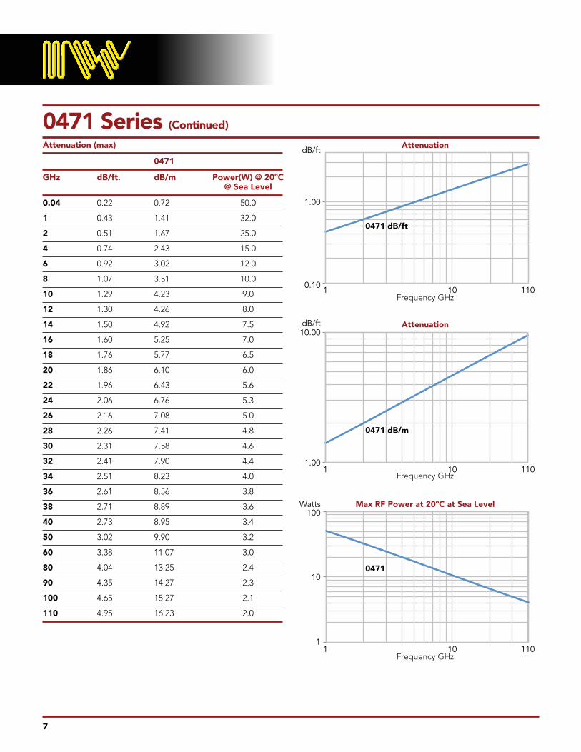
0471 Series (Continued)
Attenuation (max)
0471
GHz dB/ft. dB/m Power(W) @ 20ºC @ Sea Level
0.04 0 .22 0 .72 50 .0
1 0 .43 1 .41 32 .0
2 0 .51 1 .67 25 .0
4 0 .74 2 .43 15 .0
6 0 .92 3 .02 12 .0
8 1 .07 3 .51 10 .0
10 1 .29 4 .23 9 .0
12 1 .30 4 .26 8 .0
14 1 .50 4 .92 7 .5
16 1 .60 5 .25 7 .0
18 1 .76 5 .77 6 .5
20 1 .86 6 .10 6 .0
22 1 .96 6 .43 5 .6
24 2 .06 6 .76 5 .3
26 2 .16 7 .08 5 .0
28 2 .26 7 .41 4 .8
30 2 .31 7 .58 4 .6
32 2 .41 7 .90 4 .4
34 2 .51 8 .23 4 .0
36 2 .61 8 .56 3 .8
38 2 .71 8 .89 3 .6
40 2 .73 8 .95 3 .4
50 3 .02 9 .90 3 .2
60 3 .38 11 .07 3 .0
80 4 .04 13 .25 2 .4
90 4 .35 14 .27 2 .3
100 4 .65 15 .27 2 .1
110 4 .95 16 .23 2 .0
0.10
1.00
dB/ft
1.00
1
10
100Watts
10.00dB/ft
Attenuation
Attenuation
Max RF Power at 20ºC at Sea Level
Frequency GHz
Frequency GHz
Frequency GHz
0471
0471 dB/m
0471 dB/ft
101
101
10
110
110
1101

8
115 Series Operating Up to 62 GHz
1151 1156
Electrical Characteristics
Impedance 50 +/– 2Ω 50 +/– 2Ω
Cut Off Frequency (cable only, max) 62 GHz 62 GHz
Capacitance 29 pF/ft . 29 pF/ft .
Velocity of Propagation 71% 71%
Time Delay 1 .4 ns/ft . 1 .4 ns/ft .
Shielding Effectiveness up to 18GHz >90 dB >90 dB
Power Handling See Chart See Chart
Mechanical Characteristics:
Weight .32 oz/ft (30g/m) .32 oz/ft (30g/m)
Minimum Bend Radius inches (mm) 0 .25” (6 .5mm) 0 .25” (6 .5mm)
Environmental Characteristics:
Operating Temperature Range 1 -65ºC to +165ºC -65ºC to +165ºC
RoHS (2002/95/EC) Available on request Available on request
1+200ºC available on request
VSWR for assemblies with two straight connectors 1 .35:1 to 18 GHz 1 .35:1 to 18 GHzVSWR for assemblies with one straight and one right angle connector 1 .40:1 to 18 GHz 1 .40:1 to 18 GHzVSWR for assemblies with two right angle connectors 1 .45:1 to 18 GHz 1 .45:1 to 18 GHz
Outer JacketFEP
(2.46mm 0.097”)
BraidSilver Plated
Copper
FoilSilver Plated
Copper
DielectricPTFE
Center ConductorSilver Plated Copper
1151 Solid1156 Stranded

9
115 Series (Continued)
Attenuation (max)
1151 1156
GHz dB/ft. dB/m Power(W) dB/ft. dB/m Power(W) @ 20ºC @ 20ºC @ Sea Level @ Sea Level
0.04 0 .12 0 .39 270 0 .14 0 .45 241
1 0 .19 0 .63 220 0 .22 0 .72 196
2 0 .28 0 .92 200 0 .32 1 .05 170
4 0 .41 1 .34 120 0 .47 1 .53 107
6 0 .51 1 .68 85 0 .58 1 .91 76
8 0 .61 1 .98 75 0 .69 2 .26 67
10 0 .69 2 .26 70 0 .78 2 .57 63
12 0 .77 2 .51 65 0 .87 2 .86 58
14 0 .84 2 .75 60 0 .96 3 .14 54
16 0 .91 2 .98 55 1 .04 3 .40 49
18 0 .98 3 .20 50 1 .11 3 .65 45
20 1 .04 3 .42 45 1 .19 3 .89 40
22 1 .10 3 .62 43 1 .26 4 .13 38
24 1 .17 3 .82 42 1 .33 4 .36 38
26 1 .23 4 .02 40 1 .40 4 .58 36
28 1 .28 4 .21 39 1 .46 4 .80 35
30 1 .34 4 .40 38 1 .53 5 .01 34
32 1 .40 4 .58 37 1 .59 5 .22 33
34 1 .45 4 .76 36 1 .65 5 .43 32
36 1 .51 4 .94 35 1 .72 5 .63 31
38 1 .56 5 .11 32 1 .78 5 .83 29
40 1 .61 5 .28 30 1 .84 6 .02 27
42 1 .66 5 .45 29 1 .90 6 .22 26
44 1 .71 5 .62 28 1 .95 6 .41 25
46 1 .76 5 .79 27 2 .01 6 .60 24
48 1 .81 5 .95 26 2 .07 6 .78 23
50 1 .86 6 .11 25 2 .12 6 .97 22
52 1 .91 6 .27 25 2 .18 7 .15 22
54 1 .96 6 .43 25 2 .24 7 .33 22
56 2 .01 6 .59 23 2 .29 7 .51 21
58 2 .06 6 .74 23 2 .34 7 .69 21
60 2 .10 6 .90 22 2 .40 7 .86 20
62 2 .15 7 .05 22 2 .45 8 .04 20
0.10
1.00
dB/ft
dB/m
0.10
20
200
Watts
10.00
1.00
Attenuation
Attenuation
Max RF Power at 20ºC at Sea Level
Frequency GHz
Frequency GHz
Frequency GHz
1151
1156
1151
1156
1151
1156
101
101
10
70
70
701
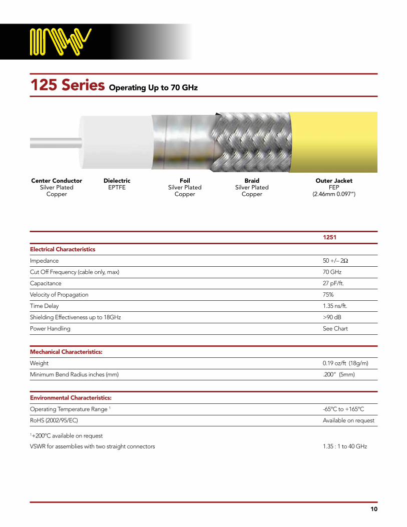
125 Series Operating Up to 70 GHz
1251
Electrical Characteristics
Impedance 50 +/– 2Ω
Cut Off Frequency (cable only, max) 70 GHz
Capacitance 27 pF/ft .
Velocity of Propagation 75%
Time Delay 1 .35 ns/ft .
Shielding Effectiveness up to 18GHz >90 dB
Power Handling See Chart
Mechanical Characteristics:
Weight 0 .19 oz/ft (18g/m)
Minimum Bend Radius inches (mm) .200” (5mm)
Environmental Characteristics:
Operating Temperature Range 1 -65ºC to +165ºC
RoHS (2002/95/EC) Available on request
1+200ºC available on request
VSWR for assemblies with two straight connectors 1 .35 : 1 to 40 GHz
10
Outer JacketFEP
(2.46mm 0.097”)
BraidSilver Plated
Copper
FoilSilver Plated
Copper
DielectricEPTFE
Center ConductorSilver Plated
Copper

11
125 Series (Continued)
Attenuation (max)
1251
GHz dB/ft. dB/m Power(W) @ 20ºC @ Sea Level
0.04 0 .12 0 .41 270
1 0 .20 0 .65 220
2 0 .28 0 .93 200
4 0 .41 1 .35 120
6 0 .51 1 .69 85
8 0 .60 1 .98 75
10 0 .68 2 .24 70
12 0 .76 2 .49 65
14 0 .83 2 .71 60
16 0 .89 2 .93 55
18 0 .96 3 .14 50
20 1 .02 3 .34 45
22 1 .08 3 .53 43
24 1 .14 3 .72 42
26 1 .19 3 .90 40
28 1 .25 4 .08 39
30 1 .30 4 .26 38
32 1 .35 4 .43 37
34 1 .40 4 .59 36
36 1 .45 4 .76 35
38 1 .50 4 .92 32
40 1 .55 5 .08 30
42 1 .59 5 .23 29
44 1 .64 5 .38 28
46 1 .69 5 .53 27
48 1 .73 5 .68 26
50 1 .78 5 .83 25
52 1 .82 5 .98 25
54 1 .87 6 .12 25
56 1 .91 6 .26 23
58 1 .95 6 .36 23
60 2 .00 6 .52 22
62 2 .04 6 .65 22
64 2 .08 6 .78 22
65 2 .10 6 .84 21
68 2 .12 6 .95 20
70 2 .14 7 .02 19
0.10
1.00
dB/ft
dB/m
Watts
0.40
10
100
4.00
Attenuation
Attenuation
Max RF Power at 20ºC at Sea Level
Frequency GHz
Frequency GHz
Frequency GHz
101
101
10
80
80
801
1251
1251
1251

140 Series Operating Up to 50 GHz
1401 1406 1403 1408
Electrical Characteristics
Impedance 50 +/– 2Ω 50 +/– 2Ω 50 +/– 2Ω 50 +/– 2Ω
Cut Off Frequency (cable only, max) 52 GHz 48 .5 GHz 52 GHz 48 .5 GHz
Capacitance 24 pF/ft . 25 pF/ft . 24 pF/ft . 25 pF/ft .
Velocity of Propagation 83% 83% 83% 83%
Time Delay 1 .22 ns/ft . 1 .22 ns/ft . 1 .22 ns/ft . 1 .22 ns/ft .
Shielding Effectiveness up to 18GHz >90 dB >90 dB >90 dB >90 dB
Power Handling See Chart See Chart See Chart See Chart
Mechanical Characteristics:
Weight .3 oz/ft (28g/m) 0 .275 oz/ft (26g/m) 0 .73 oz/ft (68g/m) 0 .73 oz/ft (68g/m)
Minimum Bend Radius inches (mm) 0 .25” (6 .4mm) 0 .25” (6 .4mm) 0 .25” (6 .4mm) 0 .25” (6 .4mm)
Environmental Characteristics:
Operating Temperature Range 1 -65ºC to +165ºC -65ºC to +165ºC -65ºC to +165ºC -65ºC to +165ºC
RoHS (2002/95/EC) Available on request Available on request Available on request Available on request
1+200ºC available on request
VSWR for assemblies with two straight 2 .4 mm connectors 1 .40 : 1 to 50 GHz 1 .40 : 1 to 50 GHz 1 .40 : 1 to 50 GHz 1 .40 : 1 to 50 GHz
12
Outer JacketFEP
(4.85mm 0.191”)
ServingSCCS Armor
Outer JacketFEP
(3.30mm 0.130”)
BraidSilver Plated
Copper
FoilSilver Plated
Copper
DielectricEPTFE
Center ConductorSilver Plated Copper
1401/1403 Solid1406/1408 Stranded

13
140 Series (Continued)
Attenuation (max)
1401/1403 1406/1408
GHz dB/ft. dB/m Power(W) dB/ft. dB/m Power(W) @ 20ºC @ 20ºC @ Sea Level @ Sea Level
0.04 0 .075 0 .25 550 0 .08 0 .28 491
1 0 .12 0 .39 450 0 .13 0 .43 402
2 0 .17 0 .55 300 0 .19 0 .62 268
4 0 .24 0 .80 225 0 .27 0 .90 201
6 0 .30 0 .99 175 0 .34 1 .11 156
8 0 .35 1 .16 150 0 .40 1 .30 134
10 0 .40 1 .32 140 0 .45 1 .47 125
12 0 .44 1 .46 120 0 .50 1 .63 107
14 0 .48 1 .59 110 0 .54 1 .78 98
16 0 .52 1 .72 105 0 .59 1 .92 94
18 0 .56 1 .83 100 0 .63 2 .05 89
20 0 .59 1 .95 95 0 .67 2 .18 85
22 0 .63 2 .06 90 0 .70 2 .30 80
24 0 .66 2 .16 85 0 .74 2 .42 76
26 0 .69 2 .27 80 0 .77 2 .54 71
28 0 .72 2 .37 75 0 .81 2 .65 67
30 0 .75 2 .46 73 0 .84 2 .76 65
32 0 .78 2 .56 71 0 .87 2 .87 63
34 0 .81 2 .65 70 0 .91 2 .97 63
36 0 .84 2 .74 68 0 .94 3 .07 61
38 0 .86 2 .83 65 0 .97 3 .17 58
40 0 .89 2 .92 60 1 .00 3 .27 54
42 0 .92 3 .01 58 1 .03 3 .37 52
44 0 .94 3 .09 56 1 .06 3 .47 50
46 0 .97 3 .18 54 1 .09 3 .56 48
48 0 .99 3 .26 52 1 .11 3 .65 46
50 1 .02 3 .34 50 N/A N/A N/A
0.10
1.00
dB/ft
dB/m
Watts
0.10
10
100
1.00
Attenuation
Attenuation
Max RF Power at 20ºC at Sea Level
Frequency GHz
Frequency GHz
Frequency GHz
101
101
10
50
50
501
1401/1403
1406/1408
1401/1403
1406/1408
1401/1403
1406/1408

150 Series Operating Up to 40 GHz
1501 1506 1503 1508
Electrical Characteristics
Impedance 50 +/– 2Ω 50 +/– 2Ω 50 +/– 2Ω 50 +/– 2Ω
Cut Off Frequency (cable only, max) 45 GHz 42 GHz 45 GHz 42 GHz
Capacitance 24 pF/ft . 26 pF/ft . 24 pF/ft . 26 pF/ft .
Velocity of Propagation 83% 83% 83% 83%
Time Delay 1 .22 ns/ft . 1 .22 ns/ft . 1 .22 ns/ft . 1 .22 ns/ft .
Shielding Effectiveness up to 18GHz >90 dB >90 dB >90 dB >90 dB
Power Handling See Chart See Chart See Chart See Chart
Mechanical Characteristics:
Weight .36 oz/ft (33g/m) 0 .34 oz/ft (31g/m) 0 .75 oz/ft (70g/m) 0 .73 oz/ft (68g/m)
Minimum Bend Radius inches (mm) 0 .5” (12 .7mm) 0 .5” (12 .7mm) 0 .75” (19mm) 0 .75” (19mm)
Environmental Characteristics:
Operating Temperature Range 1 -65ºC to +165ºC -65ºC to +165ºC -65ºC to +165ºC -65ºC to +165ºC
RoHS (2002/95/EC) Available on request Available on request Available on request Available on request
1+200ºC available on request
VSWR for assemblies with two straight 2 .9 mm connectors 1 .35 : 1 to 40 GHz 1 .35 : 1 to 40 GHz 1 .35 : 1 to 40 GHz 1 .35 : 1 to 40 GHz
14
Outer JacketFEP
(4.87mm 0.192”)
ServingSCCS Armor
Outer JacketFEP
(3.65mm 0.144”)
BraidSilver Plated
Copper
FoilSilver Plated
Copper
DielectricEPTFE
Center ConductorSilver Plated Copper
1501/1503 Solid1506/1508 Stranded

15
150 Series (Continued)
Attenuation (max)
1501/1503 1506/1508
GHz dB/ft. dB/m Power(W) dB/ft. dB/m Power(W) @ 20ºC @ 20ºC @ Sea Level @ Sea Level
0.04 0 .07 0 .23 600 0 .08 0 .26 536
1 0 .11 0 .36 500 0 .12 0 .41 446
2 0 .16 0 .51 370 0 .18 0 .58 330
4 0 .22 0 .73 260 0 .25 0 .82 232
6 0 .27 0 .90 210 0 .31 1 .01 188
8 0 .32 1 .04 180 0 .36 1 .18 161
10 0 .36 1 .17 160 0 .40 1 .32 143
12 0 .39 1 .29 150 0 .44 1 .45 134
14 0 .43 1 .40 140 0 .48 1 .58 125
16 0 .46 1 .50 125 0 .52 1 .69 112
18 0 .49 1 .60 120 0 .55 1 .80 107
20 0 .51 1 .69 115 0 .58 1 .91 103
22 0 .54 1 .78 110 0 .61 2 .01 98
24 0 .57 1 .86 105 0 .64 2 .10 94
26 0 .59 1 .94 100 0 .67 2 .20 89
28 0 .62 2 .02 99 0 .70 2 .29 88
30 0 .64 2 .10 97 0 .72 2 .37 87
32 0 .66 2 .17 95 0 .75 2 .46 85
34 0 .69 2 .25 90 0 .77 2 .54 80
36 0 .71 2 .32 85 0 .80 2 .62 76
38 0 .73 2 .39 80 0 .82 2 .70 71
40 0 .75 2 .46 75 0 .85 2 .78 67
0.10
1.00dB/ft
dB/m
Watts
0.10
10
100
1.00
Attenuation
Attenuation
Max RF Power at 20ºC at Sea Level
Frequency GHz
Frequency GHz
Frequency GHz
101
101
10
40
40
401
1501/1503
1506/1508
1501/1503
1506/1508
1501/1503
1506/1508

16
157 Series Operating Up to 40 GHz
1571 1573
Electrical Characteristics
Impedance 50 +/– 2Ω 50 +/– 2Ω
Cut Off Frequency (cable only, max) 42 GHz 42 GHz
Capacitance 24 pF/ft . 24 pF/ft .
Velocity of Propagation 83% 83%
Time Delay 1 .22 ns/ft . 1 .22 ns/ft .
Shielding Effectiveness up to 18GHz >90 dB >90 dB
Power Handling See Chart See Chart
Mechanical Characteristics:
Weight .42 oz/ft (38 .5g/m) .44 oz/ft (41g/m))
Minimum Bend Radius inches (mm) 0 .5” (12 .7mm) 0 .5” (12 .7mm)
Environmental Characteristics:
Operating Temperature Range 1 -65ºC to +165ºC -65ºC to +165ºC
RoHS (2002/95/EC) Yes Yes
1+200ºC available on request
VSWR for assemblies with two straight connectors 1 .35:1 to 18 GHz 1 .35:1 to 18 GHz
Outer JacketFEP
(5.30mm 0.209”)
ServingSCCS Armor
Outer JacketFEP
(3.98mm 0.157”)
BraidSilver Plated
Copper
FoilSilver Plated
Copper
DielectricEPTFE
Center ConductorSilver Plated Copper

17
157 Series (Continued)
Attenuation (max)
1571/1573
GHz dB/ft. dB/m Power(W) @ 20ºC @ Sea Level
0.04 0 .044 0 .146 600
1 0 .101 0 .331 500
2 0 .131 0 .431 370
4 0 .201 0 .659 260
6 0 .231 0 .759 210
8 0 .287 0 .941 180
10 0 .303 0 .933 160
12 0 .351 1 .151 150
14 0 .362 1 .188 140
16 0 .389 1 .276 125
18 0 .430 1 .410 120
20 0 .439 1 .439 160
22 0 .462 1 .515 110
24 0 .484 1 .588 105
26 0 .521 1 .709 100
28 0 .540 1 .771 99
30 0 .549 1 .801 97
32 0 .568 1 .863 95
34 0 .586 1 .922 90
36 0 .605 1 .984 85
38 0 .623 2 .044 80
40 0 .640 2 .099 75
0.100
1.000dB/ft
dB/ft
0.100
10
100
Watts
1.000
Attenuation
Attenuation
Max RF Power at 20ºC at Sea Level
Frequency GHz
Frequency GHz
Frequency GHz
101
101
10
40
40
401
1571/1573 dB/m
1571/1573 dB/ft
1571/1573

160 Series Operating Up to 32 GHz
1601 1606 1603 1608
Electrical Characteristics
Impedance 50 +/– 2Ω 50 +/– 2Ω 50 +/– 2Ω 50 +/– 2Ω
Cut Off Frequency (cable only, max) 34 GHz 34 GHz 34 GHz 34 GHz
Capacitance 29 pF/ft . 22 pF/ft . 29 pF/ft . 22 pF/ft .
Velocity of Propagation 71% 71% 71% 71%
Time Delay 1 .4 ns/ft . 1 .4 ns/ft . 1 .4 ns/ft . 1 .4 ns/ft .
Shielding Effectiveness up to 18GHz >90 dB >90 dB >90 dB >90 dB
Power Handling See Chart See Chart See Chart See Chart
Mechanical Characteristics:
Weight .48 oz/ft (44g/m) 0 .5 oz/ft (47g/m) 0 .98 oz/ft (92g/m) 0 .98 oz/ft (92g/m)
Minimum Bend Radius inches (mm) 0 .325” (8 .3mm) 0 .325” (8 .3mm) 0 .375” (9 .5mm) 0 .375” (9 .5mm)
Environmental Characteristics:
Operating Temperature Range 1 -65ºC to +165ºC -65ºC to +165ºC -65ºC to +165ºC -65ºC to +165ºC
RoHS (2002/95/EC) Available on request Available on request Available on request Available on request
1+200ºC available on request
VSWR for assemblies with two straight connectors 1 .35:1 to 18 GHz 1 .35:1 to 18 GHz 1 .35:1 to 18 GHz 1 .35:1 to 18 GHzVSWR for assemblies with one straight and one right angle connector 1 .40:1 to 18 GHz 1 .40:1 to 18 GHz 1 .40:1 to 18 GHz 1 .40:1 to 18 GHzVSWR for assemblies with two right angle connectors 1 .45:1 to 18 GHz 1 .45:1 to 18 GHz 1 .45:1 to 18 GHz 1 .45:1 to 18 GHz
18
Outer JacketFEP
(5.8mm 0.229”)
ServingSCCS Armor
Outer JacketFEP
(4.8mm 0.160”)
BraidSilver Plated
Copper
FoilSilver Plated
Copper
DielectricPTFE
Center ConductorSilver Plated Copper
1601/1603 Solid1606/1608 Stranded
19
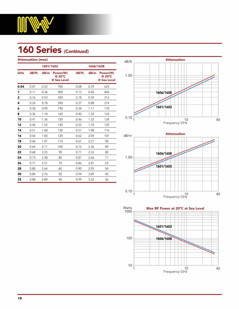
160 Series (Continued)
Attenuation (max)
1601/1603 1606/1608
GHz dB/ft. dB/m Power(W) dB/ft. dB/m Power(W) @ 20ºC @ 20ºC @ Sea Level @ Sea Level
0.04 0 .07 0 .22 700 0 .08 0 .25 625
1 0 .11 0 .36 500 0 .12 0 .40 446
2 0 .16 0 .53 350 0 .18 0 .59 313
4 0 .24 0 .78 240 0 .27 0 .88 214
6 0 .30 0 .99 190 0 .34 1 .11 170
8 0 .36 1 .18 160 0 .40 1 .32 143
10 0 .41 1 .36 150 0 .46 1 .52 134
12 0 .46 1 .52 140 0 .52 1 .70 125
14 0 .51 1 .68 130 0 .57 1 .88 116
16 0 .56 1 .83 120 0 .62 2 .04 107
18 0 .60 1 .97 110 0 .67 2 .21 98
20 0 .64 2 .11 100 0 .72 2 .36 89
22 0 .68 2 .25 90 0 .77 2 .52 80
24 0 .73 2 .38 80 0 .81 2 .66 71
26 0 .77 2 .51 70 0 .86 2 .81 63
28 0 .80 2 .64 60 0 .90 2 .95 54
30 0 .84 2 .76 50 0 .94 3 .09 45
32 0 .88 2 .89 40 0 .99 3 .23 36
0.10
1.00
dB/ft
dB/m
0.10
10
100
1000Watts
1.00
Attenuation
Attenuation
Max RF Power at 20ºC at Sea Level
Frequency GHz
Frequency GHz
Frequency GHz
101
101
10
40
40
401
1601/1603
1606/1608
1601/1603
1601/1603
1606/1608
1606/1608

20
170 Series Operating Up to 38.5 GHz
1701 1703
Electrical Characteristics
Impedance 50 +/– 2Ω 50 +/– 2Ω
Cut Off Frequency (cable only, max) 38 GHz 38 GHz
Capacitance 24 pF/ft . 24 pF/ft .
Velocity of Propagation 83% 83%
Time Delay 1 .22 ns/ft . 1 .22 ns/ft .
Shielding Effectiveness up to 18GHz >90 dB >90 dB
Power Handling See Chart See Chart
Mechanical Characteristics:
Weight .44 oz/ft (41g/m) 1 .20 oz/ft (111g/m)
Minimum Bend Radius inches (mm) 0 .25” (6 .5mm) 0 .5” (13mm)
Environmental Characteristics:
Operating Temperature Range 1 -65ºC to +165ºC -65ºC to +165ºC
RoHS (2002/95/EC) Available on request Available on request
1+200ºC available on request
VSWR for assemblies with two straight connectors 1 .35:1 to 18 GHz 1 .35:1 to 18 GHz
Outer JacketFEP
(6.09mm 0.240”)
ServingSCCS Armor
Outer JacketFEP
(4.3mm 0.170”)
BraidSilver Plated
Copper
FoilSilver Plated
Copper
DielectricEPTFE
Center ConductorSilver Plated Copper

21
170 Series (Continued)
Attenuation (max)
1701/1703
GHz dB/ft. dB/m Power(W) @ 20ºC @ Sea Level
0.04 0 .10 0 .32 850
1 0 .13 0 .43 680
2 0 .18 0 .59 467
4 0 .25 0 .86 340
6 0 .26 0 .82 270
8 0 .29 0 .95 245
10 0 .31 1 .03 210
12 0 .34 1 .13 190
14 0 .36 1 .13 178
16 0 .38 1 .17 170
18 0 .40 1 .24 165
20 0 .42 1 .31 160
22 0 .44 1 .63 157
24 0 .46 1 .42 153
26 0 .48 1 .49 148
28 0 .50 1 .56 144
30 0 .52 1 .63 136
32 0 .53 1 .73 131
34 0 .55 1 .79 127
36 0 .56 1 .84 125
38 0 .57 1 .88 120
38.5 0 .61 2 .00 119
0.10
1.00dB/ft
dB/m
0.10
100
1000Watts
1.00
Attenuation
Attenuation
Max RF Power at 20ºC at Sea Level
Frequency GHz
Frequency GHz
Frequency GHz
101
101
10
40
40
401
1701/1703
1701/1703
1701/1703

180 Series Operating Up to 32 GHz
1801 1806 1803 1808
Electrical Characteristics
Impedance 50 +/– 2Ω 50 +/– 2Ω 50 +/– 2Ω 50 +/– 2Ω
Cut Off Frequency (cable only, max) 32 GHz 31 GHz 32 GHz 31 GHz
Capacitance 24 pF/ft . 25 pF/ft . 24 pF/ft . 25 pF/ft .
Velocity of Propagation 83% 83% 83% 83%
Time Delay 1 .22 ns/ft . 1 .22 ns/ft . 1 .22 ns/ft . 1 .22 ns/ft .
Shielding Effectiveness up to 18GHz >90 dB >90 dB >90 dB >90 dB
Power Handling See Chart See Chart See Chart See Chart
Mechanical Characteristics:
Weight 0 .62 oz/ft (58g/m) 0 .6 oz/ft (54g/m) 1 .40 oz/ft (130g/m) 1 .40 oz/ft (130g/m)
Minimum Bend Radius inches (mm) 0 .5” (13mm) 0 .5” (13mm) 0 .5” (13mm) 0 .5” (13mm)
Environmental Characteristics:
Operating Temperature Range 1 -65ºC to +165ºC -65ºC to +165ºC -65ºC to +165ºC -65ºC to +165ºC
RoHS (2002/95/EC) Available on request Available on request Available on request Available on request
1+200ºC available on request
VSWR for assemblies with two straight connectors 1 .35:1 to 18 GHz 1 .35:1 to 18 GHz 1 .35:1 to 18 GHz 1 .35:1 to 18 GHzVSWR for assemblies with one straight and one right angle connector 1 .40:1 to 18 GHz 1 .40:1 to 18 GHz 1 .40:1 to 18 GHz 1 .40:1 to 18 GHzVSWR for assemblies with two right angle connectors 1 .45:1 to 18 GHz 1 .45:1 to 18 GHz 1 .45:1 to 18 GHz 1 .45:1 to 18 GHzVSWR for assemblies with two straight 3 .5mm connectors 1 .35:1 to 26 .5 GHz 1 .35:1 to 26 .5 GHz 1 .35:1 to 26 .5 GHz 1 .35:1 to 26 .5 GHz
22
Outer JacketFEP
(6.6mm 0.260”)
ServingSCCS Armor
Outer JacketFEP
(4.8mm 0.190”)
BraidSilver Plated
Copper
FoilSilver Plated
Copper
DielectricEPTFE
Center ConductorSilver Plated Copper
1801/1803 Solid1806/1808 Stranded
23
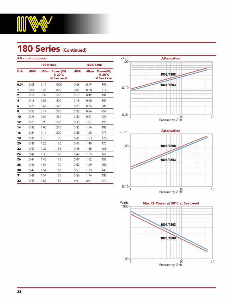
180 Series (Continued)
Attenuation (max)
1801/1803 1806/1808
GHz dB/ft. dB/m Power(W) dB/ft. dB/m Power(W) @ 20ºC @ 20ºC @ Sea Level @ Sea Level
0.04 0 .05 0 .17 1000 0 .06 0 .19 893
1 0 .08 0 .27 800 0 .09 0 .30 714
2 0 .12 0 .38 550 0 .13 0 .42 491
4 0 .16 0 .53 400 0 .18 0 .60 357
6 0 .20 0 .66 320 0 .23 0 .74 286
8 0 .23 0 .77 290 0 .26 0 .86 259
10 0 .26 0 .87 250 0 .30 0 .97 223
12 0 .29 0 .95 220 0 .33 1 .07 196
14 0 .32 1 .03 210 0 .35 1 .16 188
16 0 .34 1 .11 200 0 .35 1 .25 179
18 0 .36 1 .18 195 0 .41 1 .33 174
20 0 .38 1 .25 190 0 .43 1 .40 170
22 0 .40 1 .32 185 0 .45 1 .48 165
24 0 .42 1 .38 180 0 .47 1 .55 161
26 0 .44 1 .45 175 0 .49 1 .62 156
28 0 .46 1 .51 170 0 .52 1 .69 152
30 0 .47 1 .54 160 0 .53 1 .73 143
31 0 .48 1 .57 155 0 .56 1 .76 138
32 0 .49 1 .62 150 n/a n/a n/a
0.01
0.10
1.00dB/ft
dB/m
Watts
0.10
100
1000
1.00
Attenuation
Attenuation
Max RF Power at 20ºC at Sea Level
Frequency GHz
Frequency GHz
Frequency GHz
101
101
101
1801/1803
1806/1808
1801/1803
1806/1808
1801/1803
1806/1808
40
40
40

230 Series Operating Up to 26.5 GHz
2301 2306 2303 2308
Electrical Characteristics
Impedance 50 +/– 2Ω 50 +/– 2Ω 50 +/– 2Ω 50 +/– 2Ω
Cut Off Frequency (cable only, max) 26 .7 GHz 25 GHz 26 .7 GHz 25 GHz
Capacitance 24 pF/ft . 25 pF/ft . 24 pF/ft . 25 pF/ft .
Velocity of Propagation 83% 83% 83% 83%
Time Delay 1 .22 ns/ft . 1 .22 ns/ft . 1 .22 ns/ft . 1 .22 ns/ft .
Shielding Effectiveness up to 18GHz >90 dB >90 dB >90 dB >90 dB
Power Handling See Chart See Chart See Chart See Chart
Mechanical Characteristics:
Weight 0 .77 oz/ft (72g/m) 0 .77 oz/ft (72g/m) 1 .6 oz/ft (148g/m) 1 .6 oz/ft (148g/m)
Minimum Bend Radius inches (mm) 0 .750” (19mm) 0 .750” (19mm) 0 .625” (16mm) 0 .625” (16mm)
Environmental Characteristics:
Operating Temperature Range 1 -65ºC to +165ºC -65ºC to +165ºC -65ºC to +165ºC -65ºC to +165ºC
RoHS (2002/95/EC) Available on request Available on request Available on request Available on request
1+200ºC available on request
VSWR for assemblies with two straight connectors 1 .35:1 to 18 GHz 1 .35:1 to 18 GHz 1 .35:1 to 18 GHz 1 .35:1 to 18 GHzVSWR for assemblies with one straight and one right angle connector 1 .40:1 to 18 GHz 1 .40:1 to 18 GHz 1 .40:1 to 18 GHz 1 .40:1 to 18 GHzVSWR for assemblies with two right angle connectors 1 .45:1 to 18 GHz 1 .45:1 to 18 GHz 1 .45:1 to 18 GHz 1 .45:1 to 18 GHzVSWR for assemblies with two straight 3 .5mm connectors 1 .35:1 to 26 .5 GHz 1 .35:1 to 26 .5 GHz 1 .35:1 to 26 .5 GHz 1 .35:1 to 26 .5 GHz
24
Outer JacketFEP
(7.4mm 0.290”)
ServingSCCS Armor
Outer JacketFEP
(5.8mm 0.230”)
BraidSilver Plated
Copper
FoilSilver Plated
Copper
DielectricEPTFE
Center ConductorSilver Plated Copper
2301/2303 Solid2306/2308 Stranded

25
230 Series (Continued)
Attenuation (max)
2301/2303 2306/2308
GHz dB/ft. dB/m Power(W) dB/ft. dB/m Power(W) @ 20ºC @ 20ºC @ Sea Level @ Sea Level
0.04 0 .038 0 .125 1300 0 .043 0 .140 1161
1 0 .061 0 .200 1100 0 .068 0 .220 982
2 0 .087 0 .285 800 0 .097 0 .320 714
4 0 .125 0 .410 520 0 .14 0 .460 464
6 0 .155 0 .508 450 0 .173 0 .570 402
8 0 .180 0 .590 380 0 .202 0 .660 339
10 0 .203 0 .666 350 0 .228 0 .750 313
12 0 .224 0 .735 310 0 .251 0 .820 277
14 0 .244 0 .800 300 0 .273 0 .900 268
16 0 .263 0 .863 280 0 .294 0 .960 250
18 0 .280 0 .918 270 0 .314 1 .030 241
20 0 .297 0 .974 250 0 .332 1 .09 223
22 0 .313 1 .027 230 0 .351 1 .15 205
24 0 .329 1 .079 220 0 .368 1 .21 196
25 0 .336 1 .102 215 0 .377 1 .24 188
26.5 0 .347 1 .138 210 N/A N/A N/A
0.01
1.00dB/ft
dB/m
Watts
0.1
0.100
100
1000
1.000
Attenuation
Max RF Power at 20ºC at Sea Level
Attenuation
Frequency GHz
Frequency GHz
Frequency GHz
101
101
10
30
30
301
2301/2303
2306/2308
2301/2303
2306/2308
2301/2303
2306/2308

280 Series Operating Up to 18 GHz
2801 2806 2803 2808
Electrical Characteristics
Impedance 50 +/– 2Ω 50 +/– 2Ω 50 +/– 2Ω 50 +/– 2Ω
Cut Off Frequency (cable only, max) 19 .5 GHz 18 GHz 19 .5 GHz 18 GHz
Capacitance 24 pF/ft . 24 pF/ft . 24 pF/ft . 24 pF/ft .
Velocity of Propagation 83% 83% 83% 83%
Time Delay 1 .22 ns/ft . 1 .22 ns/ft . 1 .22 ns/ft . 1 .22 ns/ft .
Shielding Effectiveness up to 18GHz >90 dB >90 dB >90 dB >90 dB
Power Handling See Chart See Chart See Chart See Chart
Mechanical Characteristics:
Weight 1 .40 oz/ft (130g/m) 1 .30 oz/ft (120g/m) 2 .50 oz/ft (230g/m) 2 .50 oz/ft (230g/m)
Minimum Bend Radius inches (mm) 1” (25 .4mm) 1” (25 .4mm) 1” (25 .4mm) 1” (25 .4mm)
Environmental Characteristics:
Operating Temperature Range 1 -65ºC to +165ºC -65ºC to +165ºC -65ºC to +165ºC -65ºC to +165ºC
RoHS (2002/95/EC) Available on request Available on request Available on request Available on request
1+200ºC available on request
VSWR for assemblies with two straight connectors 1 .35:1 to 18 GHz 1 .35:1 to 18 GHz 1 .35:1 to 18 GHz 1 .35:1 to 18 GHzVSWR for assemblies with one straight and one right angle connector 1 .40:1 to 18 GHz 1 .40:1 to 18 GHz 1 .40:1 to 18 GHz 1 .40:1 to 18 GHzVSWR for assemblies with two right angle connectors 1 .45:1 to 18 GHz 1 .45:1 to 18 GHz 1 .45:1 to 18 GHz 1 .45:1 to 18 GHz
26
Outer JacketFEP
(9.65mm 0.380”)
ServingSCCS Armor
Outer JacketFEP
(7.74mm 0.305”
BraidSilver Plated
Copper
FoilSilver Plated
Copper
DielectricEPTFE
Center ConductorSilver Plated Copper
2801/2803 Solid2806/2808 Stranded
27
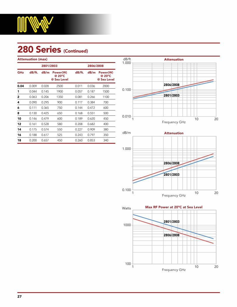
280 Series (Continued)
Attenuation (max)
2801/2803 2806/2808
GHz dB/ft. dB/m Power(W) dB/ft. dB/m Power(W) @ 20ºC @ 20ºC @ Sea Level @ Sea Level
0.04 0 .009 0 .028 2500 0 .011 0 .036 2000
1 0 .044 0 .145 1900 0 .057 0 .187 1500
2 0 .063 0 .206 1350 0 .081 0 .266 1100
4 0 .090 0 .295 900 0 .117 0 .384 700
6 0 .111 0 .365 750 0 .144 0 .472 600
8 0 .130 0 .425 650 0 .168 0 .551 500
10 0 .146 0 .479 600 0 .189 0 .620 450
12 0 .161 0 .528 580 0 .208 0 .682 400
14 0 .175 0 .574 550 0 .227 0 .909 380
16 0 .188 0 .617 525 0 .243 0 .797 350
18 0 .200 0 .657 450 0 .260 0 .853 340
0.010
1.000
0.100
100
1000
0.100
1.000
dB/m
dB/ft
Watts
Attenuation
Attenuation
Max RF Power at 20ºC at Sea Level
Frequency GHz
Frequency GHz
Frequency GHz
101
101
10
20
20
201
2801/2803
2806/2808
2801/2803
2806/2808
2801/2803
2806/2808

28
480 Series Operating Up to 11 GHz
4806
Electrical Characteristics
Impedance 50 +/– 2Ω
Cut Off Frequency (cable only, max) 11 .5 GHz
Capacitance 24 pF/ft .
Velocity of Propagation 83%
Time Delay 1 .22 ns/ft .
Shielding Effectiveness up to 18GHz >90 dB
Power Handling See Chart
Mechanical Characteristics:
Weight 2 .9 oz/ft (267g/m)
Minimum Bend Radius inches (mm) 3 .0” (76 .2mm)
Environmental Characteristics:
Operating Temperature Range 1 -65ºC to +165ºC
RoHS (2002/95/EC) Available on request
1+200ºC available on request
VSWR for assemblies with two straight connectors 1 .35:1 to 11 GHz
Outer JacketFEP
(12.mm 0.480”)
BraidSilver Plated
Copper
FoilSilver Plated
Copper
DielectricEPTFE
Center ConductorSilver Plated
Copper(Stranded only)

29
480 Series (Continued)
Attenuation (max)
4806
GHz dB/ft. dB/m Power(W) @ 20ºC @ Sea Level
.04 0 .006 0 .020 7500
1 0 .030 0 .098 3250
2 0 .043 0 .141 2260
4 0 .064 0 .210 1650
6 0 .080 0 .262 1300
8 0 .095 0 .312 1100
10 0 .109 0 .358 950
11 0 .116 0 .380 900
0.01
0.1
dB/ft
dB/m
Watts
0.010
100
1000
0.100
Attenuation
Attenuation
Max RF Power at 20ºC at Sea Level
Frequency GHz
Frequency GHz
Frequency GHz
101
101
10
12
12
121
4806
4806
4806
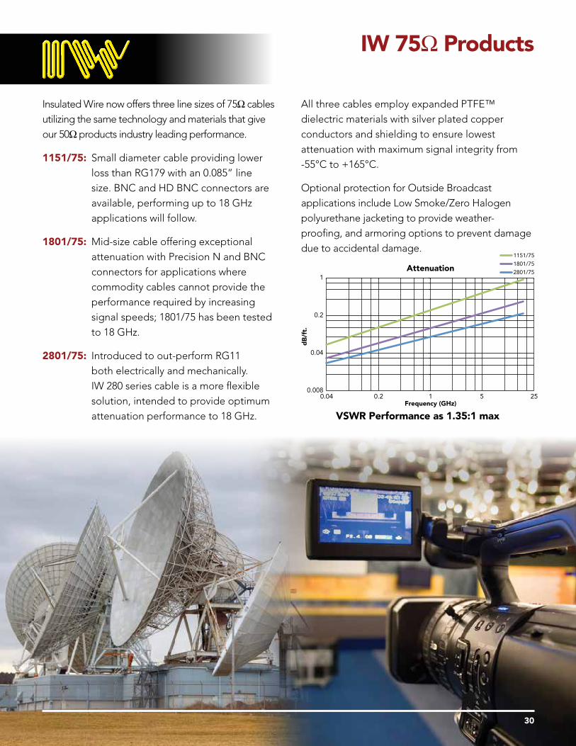
Insulated Wire now offers three line sizes of 75Ω cables utilizing the same technology and materials that give our 50Ωproducts industry leading performance .
1151/75: Small diameter cable providing lower loss than RG179 with an 0 .085” line size . BNC and HD BNC connectors are available, performing up to 18 GHz applications will follow .
1801/75: Mid-size cable offering exceptional attenuation with Precision N and BNC connectors for applications where commodity cables cannot provide the performance required by increasing signal speeds; 1801/75 has been tested to 18 GHz .
2801/75: Introduced to out-perform RG11 both electrically and mechanically . IW 280 series cable is a more flexible solution, intended to provide optimum attenuation performance to 18 GHz .
All three cables employ expanded PTFE™ dielectric materials with silver plated copper conductors and shielding to ensure lowest attenuation with maximum signal integrity from -55°C to +165°C .
Optional protection for Outside Broadcast applications include Low Smoke/Zero Halogen polyurethane jacketing to provide weather-proofing, and armoring options to prevent damage due to accidental damage .
VSWR Performance as 1.35:1 max
IW 75Ω Products
30
1
0.2
0.04
0.008
Attenuation
0.04 0.2 1Frequency (GHz)
dB
/ft.
5 25
1151/75
1801/75
2801/75

To provide improved electrical and mechanical
performance over traditional hand-formable
designs, Insulated Wire presents Re-Flex™ .
Available in 0 .085”, 0 .141” and 0 .235” diameters
(identified as RF085, RF141 and RF250), IW’s
RF cable series offers the advantages of the
same lamination process used on our Low Loss
products . Combined with the same double shield
construction plus a solder-free tin/alloy plated outer
braid, the Re-Flex™ design provides a re-formable
cable that will not develop micro-fractures with
repeated flexing, eliminating manufacturability
issues associated with conformable style RG cables .
Both RF085 and RF141 are industry standard line
sizes, consequently a wide range of connector types
and styles can be used with these cables, including:
SMA, TNC, N, GPO™, GPPO™, 2 .92mm/K™,
2 .4mm and 1 .85mm/V™, with performance up
to 60GHz . RF250 is commonly used for higher
power applications with SMA, TNC, N, SC and HN
connectors available .
Re-Flex™ assemblies can be employed wherever
a semi-rigid or conformable cable type is currently
used, and with FEP™ jacket available as a standard
option, Re-Flex™ provides greater versatility . Cable
part numbers are TPRFEP085, TPRFEP141 and
TPRFEP250 . Just ask our customers.
Re-Flex™ Products
31
Re-Flex™ Cable - Key Performance Parameters
Cable Maximum Frequency Attenuation (dB/ft., max) Bend Radius Replaces Type (cable only) 10 GHz 18 GHz 32 GHz 60 GHz (inch)
RF085 62 GHz 0.60 0.91 1.28 2.01 0.125 RG405 RF141 34 GHz 0.41 0.60 0.88 - 0.250 RG402 RF250 19.5 GHz 0.29 0.44 - - 0.375 RG401
Re-Flex™ Cable - Availability
Cable AMS-DTL-23053 FEP Jacket Distribution Stock Type Jacket Available Available RF085 Yes Yes SMA (m) to SMA (m) direct solder, 3” and up RF141 Yes Yes SMA (m) to SMA (m) direct solder, 3” and up SMA (m) to SMA (m) shell style, 2” and up RF250 Yes Yes -

32
RF085 Series Operating Up to 62 GHz
RF085
Electrical Characteristics
Impedance 50 +/– 2Ω
Cut Off Frequency (cable only, max) 62 GHz
Capacitance 29 pF/ft .
Velocity of Propagation 71%
Time Delay 1 .40 ns/ft .
Shielding Effectiveness up to 18GHz >90 dB
Power Handling See Chart
Mechanical Characteristics:
Weight .17 oz/ft (16g/m)
Minimum Bend Radius inches (mm) .125” (3 .175mm)
Environmental Characteristics:
Operating Temperature Range 1 -65ºC to +165ºC
RoHS (2002/95/EC) Available on request
VSWR for assemblies with two straight connectors 1 .35:1 to 18 GHz
FEP Jacket available – Cable part number TPRFEP085
BraidTin Plated Copper
(2.15mm 0.085”)
FoilSilver Plated
Copper
DielectricPTFE
Center ConductorSilver Plated
Copper

33
RF085 Series (Continued)
Insertion Loss
RF085
GHz dB/ft. dB/m Power(W) @ 20ºC @ Sea Level
0.04 0 .12 0 .39 270
1 0 .19 0 .63 220
2 0 .28 0 .92 200
4 0 .41 1 .34 120
6 0 .51 1 .68 85
8 0 .61 1 .98 75
10 0 .69 2 .26 70
12 0 .77 2 .51 65
14 0 .84 2 .75 60
16 0 .91 2 .98 55
18 0 .98 3 .20 50
20 1 .04 3 .42 45
22 1 .10 3 .62 43
24 1 .17 3 .82 42
26 1 .23 4 .02 40
28 1 .28 4 .21 39
30 1 .34 4 .40 39
32 1 .40 4 .58 37
34 1 .45 4 .76 36
36 1 .51 4 .94 35
38 1 .56 5 .11 32
40 1 .61 5 .28 30
42 1 .66 5 .45 29
44 1 .71 5 .62 28
46 1 .76 5 .79 27
48 1 .81 5 .95 26
50 1 .86 6 .11 25
52 1 .91 6 .27 25
54 1 .96 6 .43 25
56 2 .01 6 .59 23
58 2 .06 6 .74 23
60 2 .10 6 .90 22
62 2 .15 7 .05 22
0.10
1.00
dB/ft
dB/m
Watts
1.00
1
10
100
10.00
Attenuation
Attenuation
Frequency GHz
Frequency GHz
Frequency GHz
101
101
10
62
62
621
RF085
RF085
RF085
Max RF Power at 20ºC at Sea Level

34
RF141 Series Operating Up to 34 GHz
RF141
Electrical Characteristics
Impedance 50 +/– 2Ω
Cut Off Frequency (cable only, max) 34 GHz
Capacitance 29 pF/ft .
Velocity of Propagation 71%
Time Delay 1 .40 ns/ft .
Shielding Effectiveness up to 18GHz >90 dB
Power Handling See Chart
Mechanical Characteristics:
Weight .402 oz/ft (37g/m)
Minimum Bend Radius inches (mm) .250” (6 .4mm)
Environmental Characteristics:
Operating Temperature Range 1 -65ºC to +165ºC
RoHS (2002/95/EC) Available on request
VSWR for assemblies with two straight connectors 1 .35:1 to 18 GHz
FEP Jacket available – Cable part number TPRFEP141
BraidTin Plated Copper
(3.58mm 0.141”)
FoilSilver Plated
Copper
DielectricPTFE
Center ConductorSilver Plated
Copper

35
RF141 Series (Continued)
Insertion Loss
RF141
GHz dB/ft. dB/m Power(W) @ 20ºC @ Sea Level
0.04 0 .07 0 .22 700
1 0 .11 0 .36 500
2 0 .16 0 .53 350
4 0 .24 0 .78 240
6 0 .30 0 .99 190
8 0 .36 1 .18 160
10 0 .41 1 .36 150
12 0 .46 1 .52 140
14 0 .51 1 .68 130
16 0 .56 1 .83 120
18 0 .60 1 .97 110
20 0 .64 2 .11 100
22 0 .68 2 .25 90
24 0 .73 2 .38 80
26 0 .77 2 .51 70
28 0 .80 2 .64 60
30 0 .84 2 .76 50
32 0 .88 2 .89 40
34 0 .92 3 .01 30
0.10
1.00dB/ft
dB/m
Watts
0.10
1
10
100
1000
1.00
Attenuation
Attenuation
Frequency GHz
Frequency GHz
Frequency GHz
101
101
10
40
40
401
RF141
RF141
RF141
Max RF Power at 20ºC at Sea Level
36
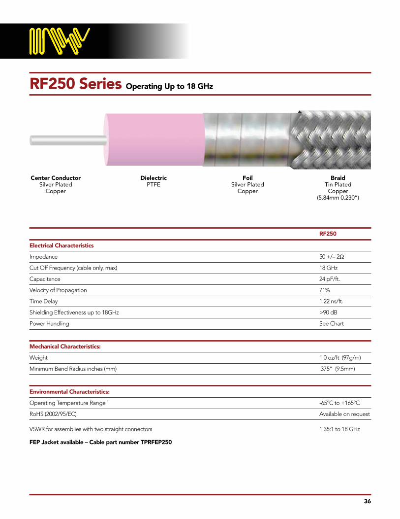
RF250 Series Operating Up to 18 GHz
RF250
Electrical Characteristics
Impedance 50 +/– 2Ω
Cut Off Frequency (cable only, max) 18 GHz
Capacitance 24 pF/ft .
Velocity of Propagation 71%
Time Delay 1 .22 ns/ft .
Shielding Effectiveness up to 18GHz >90 dB
Power Handling See Chart
Mechanical Characteristics:
Weight 1 .0 oz/ft (97g/m)
Minimum Bend Radius inches (mm) .375” (9 .5mm)
Environmental Characteristics:
Operating Temperature Range 1 -65ºC to +165ºC
RoHS (2002/95/EC) Available on request
VSWR for assemblies with two straight connectors 1 .35:1 to 18 GHz
FEP Jacket available – Cable part number TPRFEP250
BraidTin Plated Copper
(5.84mm 0.230”)
FoilSilver Plated
Copper
DielectricPTFE
Center ConductorSilver Plated
Copper

37
RF250 Series (Continued)
Insertion Loss
RF250
GHz dB/ft. dB/m Power(W) @ 20ºC @ Sea Level
0.04 0 .03 0 .10 1300
1 0 .07 0 .23 1100
2 0 .11 0 .36 800
4 0 .17 0 .56 520
6 0 .22 0 .72 450
8 0 .26 0 .85 380
10 0 .29 0 .95 350
12 0 .34 1 .12 310
14 0 .37 1 .21 300
16 0 .41 1 .34 280
18 0 .44 1 .44 270
0.01
0.10
1.00dB/ft
0.10
100
1000
Watts
1.00
10.00dB/m
Attenuation
Attenuation
Frequency GHz
Frequency GHz
Frequency GHz
101
101
10
20
20
201
Max RF Power at 20ºC at Sea Level
RF250
RF250
RF250

CT-1879 (SPSD-TPRF085-XXX-SPSD) direct solder
SMA male/male using TPRF085 (RG405 line size)
CT-1880 (SPSD-TPRF141-XXX-SPSD) direct solder
SMA male/male using TPRF141 (RG402 line size)
CT-1881 (SPSH-TPRF141-XXX-SPSH) shell style
SMA male/male using TPRF141 (RG402 line size)
Each kit comprises seven different assembly lengths
3”, 4”, 5”, 6”, 8”, 9” and 12”, 6 pcs of each,
providing the design engineer with a convenient aid
for performing cable routing in prototype system
builds – the ability to continually re-form Re-Flex
without the need for custom tooling to shape the
cable, and the elimination of debris caused by
micro fracturing is a key feature of the Re-Flex
cable design, and enables the designer to make
signal path/layout changes without having to throw
product away after using it once.
Re-Flex™ Starter Kits
38
Re-formable cable assembly solutions straight out of the box!
For customers who know the advantages of Re-Flex over traditional hand-formable and semi-rigid, and to
make cable selection easier for those new to our product, IW is pleased to announce our new range of
Re-Flex Starter Kits!
Three kits are currently available:

This catalog lists the most common configurations
for each cable type. If necessary, IW can modify
existing designs or design a custom connector to
meet your specific requirements. Our standard
connectors meet the environmental specifications
of MIL-PRF-39012. See table on page 34 for
maximum operating frequency.
Connector Options
39
Materials & Finishes
Component Material Specifications Finish Specifications
Bodies Stainless Steel per Passivation per SAE-AMS-2700 AMS-5640 UNS-S30300, Type 1
Coupling Nut Stainless Steel per Passivation per SAE-AMS-2700 AMS-5640 UNS-S30300, Type 1
Contacts Beryllium Copper per ASTM-B-196 Gold Plated per ASTM-B-488 Brass per ASTM-B-16 Gold Plated per ASTM-B-488
Solder Ferrule Brass per ASTM-B-16 Gold Plated per ASTM-B-488
Dielectric PTFE (polytetrafluoroethylene) per ASTM-D-1710 Kel-F ASTM-D-1430-03 ULTEM* (Grade 1000) *Trademark General Electric Corporation
Gasket Silicone Rubber per A-A-59588 Viton ASTM-D-1418

Choose Your Connector
Cable Frequency (GHz)Series 4 11 18 26.5 32 40 50 65 70
0471 SMA, 2.92mm (KTM), 2.4mm, 1.85mm (VTM), GPO/GPPO
115 GPO/GPPO, 1.85mm (VTM), 2.4mm, 2.92mm (KTM)
125 GPO/GPPO, 1.85mm (VTM)
140 SMA, 3.5mm, 2.4mm, 2.92mm (KTM)
150 SMA, TNCA, N, 3.5, 2.4, 2.92mm (KTM)
157 2.4mm & 2.92mm (KTM)
160 N, SMA, TNCA, SMP, KTM
170 2.92mm (KTM)
180 N, SMA, TNCA, 3.5mm, 2.92mm (KTM)
230 N, SMA, TNCA, SC, 3.5mm
280 N, SMA, TNCA, SC
480 N, 7/16, SC & C
RF085 Industry Standard 085 SR Connectors
RF141 Industry Standard 141 SR Connectors
RF250 SMA, TNCA, N, SC
Connector Optionscontinued
40
Connector Insertion Loss (per connector) (F in GHz)
Cable Connector Maximum Cable Straight Right AngleSeries Type Frequency (GHz) (dB) (dB)
0471 SMA, 2 .92mm (KTM), 2 .4mm, 1 .85mm (VTM), GPO/GPPO 60 .012 x F .017 x F 115 GPO/GPPO, 1 .85mm (VTM), 2 .4mm, 2 .92mm (KTM) 60 .012 x F .017 x F 125 GPO/GPPO, 1 .85mm (VTM) 67 .005 x F N/A 140 2 .4 mm 50 .01 x F N/A 150 SMA, TNCA, N, 3 .5, 2 .4, 2 .92mm (KTM) 45 .01 x F N/A 157 2 .4mm & 2 .92mm (KTM) 40 .01 x F N/A 160 N, SMA, TNCA, SMP, KTM 22 .012 x F .017 x F 170 2 .92mm (KTM) 18 .012 x F .017 x F 180 N, SMA, TNCA 18 .012 x F .017 x F 3 .5 mm/2 .92mm (KTM) 26 .5 .01 x F N/A 230 N, SMA, TNCA, SC 18 .012 x F .017 x F 3 .5 mm 26 .5 .01 x F N/A 280 N, SMA, TNCA, SC 22 .012 x F .017 x F 480 N, 7/16, SC & C 11 .012 x F .017 x F RF085 Industry Standard 085 SR Connectors 60 .012 x F .017 x F
RF141 Industry Standard 141 SR Connectors 26 .5 .01 x F N/A
RF250 SMA, TNCA, N, SC 18 .012 x F .017 x F
Connector types listed are preferred matching for referenced cables . Additional connector types can be provided . Please consult factory .

Cable Assembly Part Number Builder
Connector Codes B BNC G GPO GG GPPO K 2.92 mm (KTM) MB SMB MC SMC N N O OSP*/BMA S SMA SC SC SS SSMA T TNCA V 1.85 mm (VTM) Z1 ZMA-90º Z2 ZMA-120º Z3 ZMA-130/130/100 Z4 ZMA-110/110/140 7 7 mm 3 3.5 mm 2 2.4 mm* OSP is a trademark of MA/COM
Type Codes J Jack P Plug
Style Codes B Bulkhead mount O Obtuse angle (135˚) P2 2 hole panel mount P4 4 hole panel mount R Right angle RW Right angle w/ wire holes RX Extended right angle S Straight SD Straight Direct Solder SH Shell type SW Straight w/ wire holes
Optional Protection (see page 45) A Stainless steel flexible armor N Black neoprene jacket NX Nomex LC Low Smoke / Zero
Halogen polyurethane† LC – LS/ZH jacket is available for 140-480
series cables, including 03/06/08; not recommended for Re Flex™. LC jacket can be combined with external armor code ‘A’ for maximum crush resistance in outdoor environments.
†† Neoprene, ‘N’ can be applied to all cable types.
Please consult the factory for custom/application specific jacket requirements.
Differentiator Codes 1 Solid center conductor 3 Tuf-Flex™ solid center
conductor 6 Stranded conductor 8 Tuf-Flex™ stranded
center conductor
41

With so many variables involved in creating custom wires for multiple purposes, IW has devised an Part Number (P/N) Coding System which we use to readily identify all our microwave
cables . In the first example part number below, the cable assembly is an SMA right angle plug to a 2301 armored cable at 36” long to an SMA straight plug .
Cable Part Number
Cable Part Number
Assembly Length(in tenths of an inch)
Assembly Length(in centimeters)
Protection(optional)
Protection(optional)
Differentiator
Differentiator
Connector Code
Connector Code
Type Code
Type Code
Style Code
Style Code
Cable Assembly Part Number Builder
42
SPR - 2301A - 360 - SPS
SPR - 2301A - 300M - SPS
KJR - 2PS
Note: Metric part number format is X.XX meters – 300M defines a 3m length assembly; a 10m assembly part number with the same connectors as shown above is SPR-2301A-1000M-SPS
METRIC PART NUMBER
STANDARD PART NUMBER
ADAPTER PART NUMBER
Connector Code
Type Code
Style Code

43
KJR
KJS
KPR
KPS
NJB
NJP4
NJS
NPR
NPS
SCJS
SCPS
SJS
SPS
TJB
TJP4
TJS
TPS
2JS
2PS
3JS
3PS
KJS
X
X
X
X
X
X
KPS
X
X
X
X
X
X
X
NJS
X
X
X
X
X
X
X
X
X
NPS
X
X
X
X
X
X
X
X
X
SCJS
X
X
SCPS
X
X
SJS
X
X
X
X
X
X
X
X
X
X
SPS
X
X
X
X
X
X
X
X
TJB
X
X
X
TJP4
X
TJS
X
X
X
X
X
X
X
TPS
X
X
X
X
X
X
X
2JS
X
X
X
X
X
X
2PS
X
X
X
X
X
3JS
X
X
X
X
X
3PS
X
X
X
X
X
7S
X
X
X
X
X
X
X
X
Coaxial Adapters Part Numbers
44
Additional styles available. Consult factory.
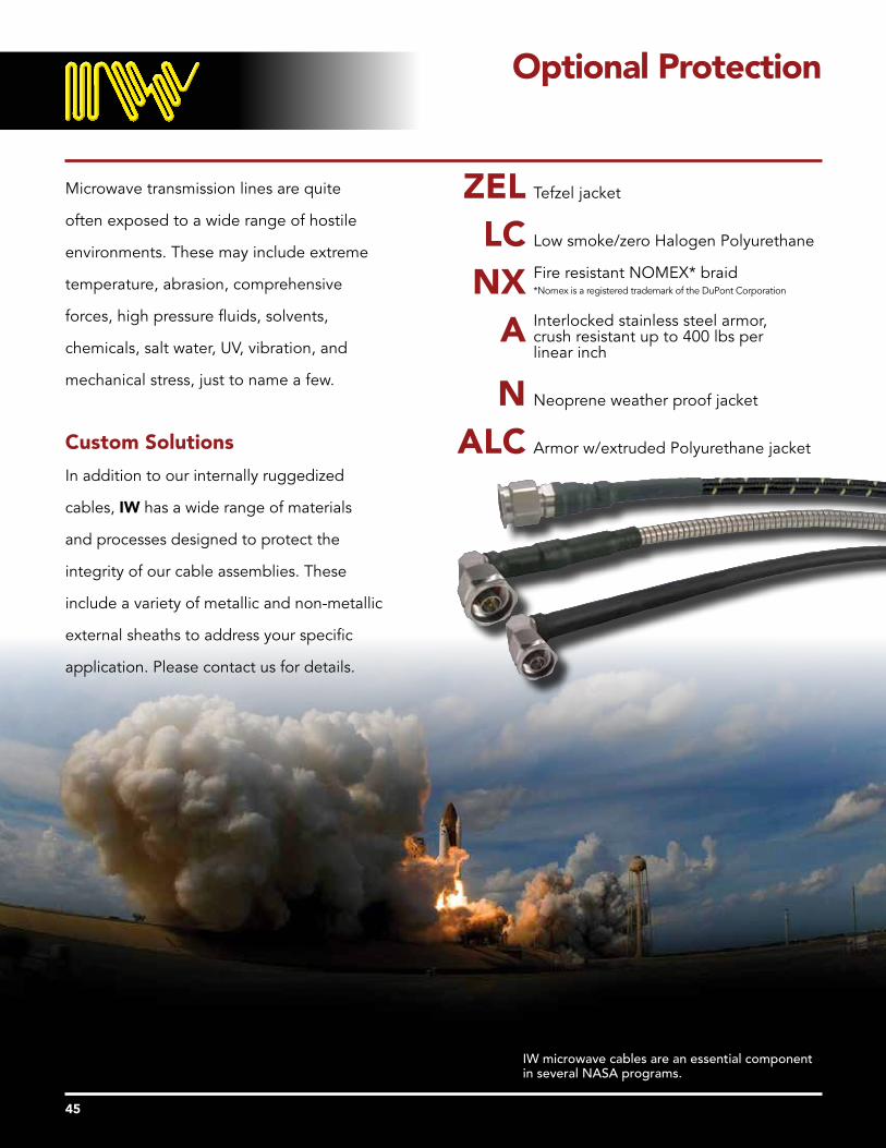
Microwave transmission lines are quite
often exposed to a wide range of hostile
environments. These may include extreme
temperature, abrasion, comprehensive
forces, high pressure fluids, solvents,
chemicals, salt water, UV, vibration, and
mechanical stress, just to name a few.
Custom Solutions
In addition to our internally ruggedized
cables, IW has a wide range of materials
and processes designed to protect the
integrity of our cable assemblies. These
include a variety of metallic and non-metallic
external sheaths to address your specific
application. Please contact us for details.
ZEL Tefzel jacket
LC Low smoke/zero Halogen Polyurethane Fire resistant NOMEX* braid NX *Nomex is a registered trademark of the DuPont Corporation
Interlocked stainless steel armor, A crush resistant up to 400 lbs per linear inch
N Neoprene weather proof jacket ALC Armor w/extruded Polyurethane jacket
Optional Protection
45
IW microwave cables are an essential component in several NASA programs.

L
MARKER LABEL *
L
MARKER LABEL *
L
MARKER LABEL *
L
MARKER LABEL *
Assembly Length Definition
46
The outlines below show typical cable assembly configurations and reference points to determine overall length .
* A center marker label is fitted to all assemblies over 6” in length; two markers located close to the cable ends are fitted for asemblies greater than 10ft ./120”/3m .
Length in Tol In Length metric Tol in metric 6” to < 12” +0 .50”/-0 .00 16 cm to < 30 cm +1 .5 cm/-0 .00 12” to <72” +1 .00”/-0 .00 30 cm to <180 cm +3 cm/-0 .00 72” < Length +2 .00”/-0 .00 180 cm < Length +6 cm/-0 .00
Note: For reflex assemblies with SMA direct solder or shell style connectors, the tolerances are…
2” to < 36” ±0 .100” 36” to <72” ±0 .250” 72” < Length ±0 .500”
Fig . 1 – NPS-XXXX-XXX-SPS
Fig . 4 – SPS-XXXX-XXX-NJB
Fig . 3 – TPR-XXXX-XXX-TPR
Fig . 2 – TPS-XXXX-XXX-SPRC
-700
-600
-500
-400
-300
-200
-100
0
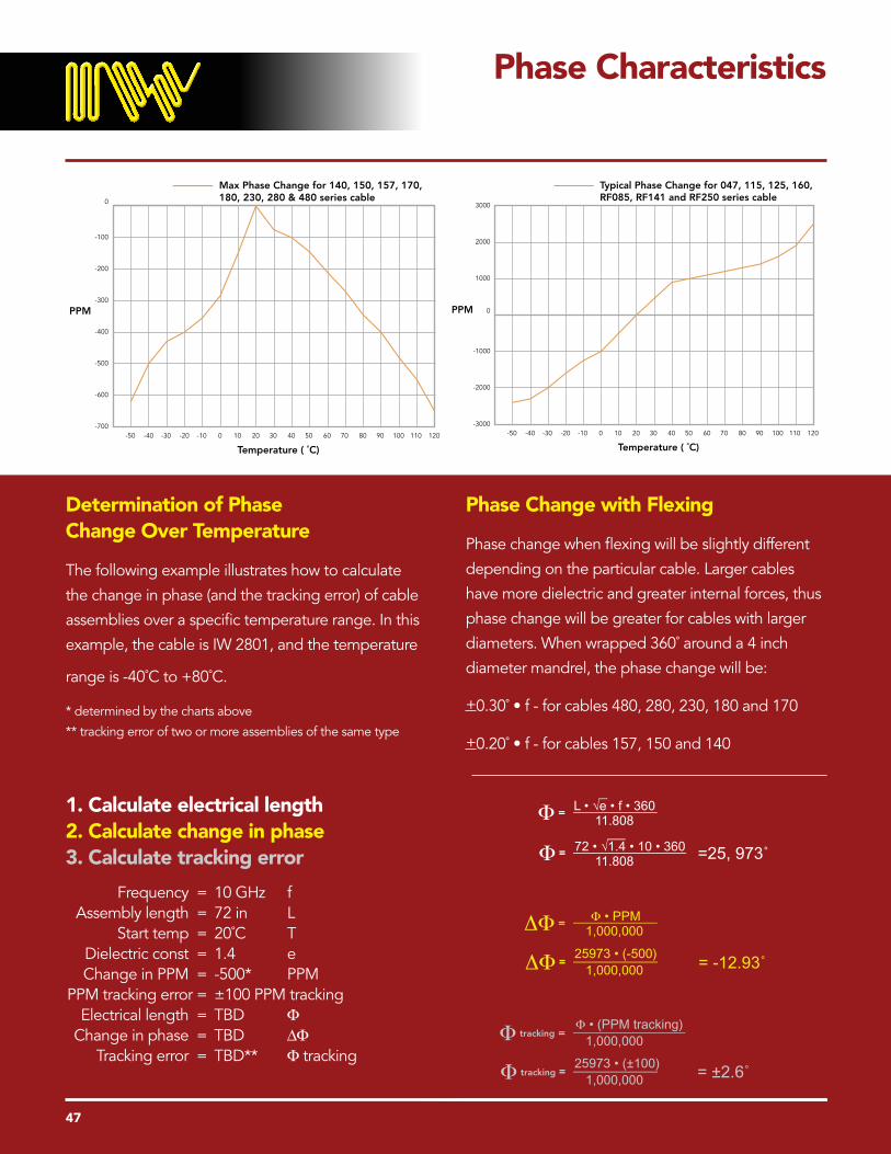
Max Phase Change for 140, 150, 157, 170, 180, 230, 280 & 480 series cable
-40 -20 0 20 40 60 80 100 120-50 -30 -10 10 30 50 70 90 110
PPM
Temperature ( ˚C)
Phase Characteristics
47
Determination of Phase Change Over Temperature
The following example illustrates how to calculate
the change in phase (and the tracking error) of cable
assemblies over a specific temperature range. In this
example, the cable is IW 2801, and the temperature
range is -40˚C to +80˚C.
* determined by the charts above
** tracking error of two or more assemblies of the same type
Phase Change with Flexing
Phase change when flexing will be slightly different
depending on the particular cable. Larger cables
have more dielectric and greater internal forces, thus
phase change will be greater for cables with larger
diameters. When wrapped 360˚ around a 4 inch
diameter mandrel, the phase change will be:
+0.30˚ • f - for cables 480, 280, 230, 180 and 170
+0.20˚ • f - for cables 157, 150 and 140
1. Calculate electrical length 2. Calculate change in phase 3. Calculate tracking error
Frequency = 10 GHz f Assembly length = 72 in L Start temp = 20˚C T Dielectric const = 1.4 e Change in PPM = -500* PPM PPM tracking error = ±100 PPM tracking Electrical length = TBD F Change in phase = TBD DF Tracking error = TBD** F tracking
-3000
-2000
-1000
0
1000
2000
3000
Typical Phase Change for 047, 115, 125, 160, RF085, RF141 and RF250 series cable
-40 -20 0 20 40 60 80 100 120-50 -30 -10 10 30 50 70 90 110
PPM
Temperature ( ˚C)
=25, 973˚
= -12.93˚
= ±2.6˚
L • √e • f • 36011.808Φ =
72 • √1.4 • 10 • 36011.808Φ =
Φ • PPM1,000,000ΔΦ =
25973 • (-500)1,000,000ΔΦ =
Φ • (PPM tracking)1,000,000Φ tracking =
25973 • (±100)1,000,000Φ tracking =

For applications where phase or electrical length is
a critical performance parameter, IW can provide
matched assembly sets, tested to customer
specifications, typically up to 40 GHz, with both
Low Loss Phase Stable and Re-Flex™ cable types .
Relative phase matching is a common
requirement achieved with multiple assembly
sets . Typical phase matching tolerances are shown
in Table 1 below .
Tighter tolerances may be achievable; IW
engineers review all matching requirements on a
case by case basis . In addition, IW also provides
time delay matched assemblies with tolerances in
the order of 2pS being achievable with both Low
Loss and Re-Flex™ cable types, and individual
assemblies can also be supplied trimmed to a
specific electrical length .
All matched assemblies are tested 100% for
insertion loss and VSWR performance parameters
in addition to phase .
Phase Match and Time Delay
48
Frequency (GHz) Phase Match (degrees)
10 ± 2
18 ± 3.5
26.5 ± 5
40 ± 8

-140
-130
-120
-110
-100
-90
-80
-70RF Leakage
0 2 4 6 8 10 12 14 16 18Frequency (GHz)
RF
Leak
age
(dB
)
0102030405060708090
100Power Rating VS. Temperature
250 50 75 100 125 150 175 200 225 250Temperature (˚C)
PW
R R
atin
g (%
of
25˚C
)
0102030405060708090
100Power Rating VS. Altitude
100 20 30 40 50 60 70 80Altitude (ft x 1000)
PW
R R
atin
g (%
of
Sea
Leve
l)
Coaxial TransmissionLine Equations
RF Leakage (IW 1801)
Power Rating
Insertion Loss vs. Temperature
dBT = α20 √.0038 (T-20) +1Use this equation to determine cable loss (dBT) at any temperature (T) in degrees Celcius. α20 is the cable loss at 20˚C
Measured values of IW 1801 cable using the test method specified in MIL-T-81490.
Engineering Design Data
49
Impedance (Ω)
Cut Off Frequency (GHz)
Velocity of Propogation (%)
Outer Conductor Loss (dB)
Inner Conductor Loss (dB)
Dielectric Loss (dB)
Reflection Loss (dB)
Time Delay (ns/ft)
Capacitance (pf/ft)
138.059 • log10√ε
Zo =Dd ( )
7.52√ε • (D + d)
fco =
100√ε
Vρ =
2.745 • 10-4
ZoAc = √ρf
KolD ( )
2.745 • 10-4
ZoAc = √ρf
KilD ( )
(23.15 • 10-10) • √ε • f • tan δ • l Ad =
10 log10Ar =(VSWR +1)2
4(VSWR) [ ]
1.016 √εTD =
Inner diameter of outer conductor (inches)D =
Outer diameter of inner conductor (inches)d =
Dielectric constantε =
Resistivity in Ohm-cm ρ =
Frequency in Hertzf =
Length in inchesl =Characteristic impedanceZo =
Outer conductor stranding factorKo =
Inner conductor stranding factorKi =
Loss tangent of dielectric tan δ =
1.016 √εC = Z

IW’s range of Tuf-Flex™ cables was introduced
to provide a high level of crush resistance for
applications where an unarmored cable could be
subject to damage, e .g . long assemblies used in
a test chamber; down-mast, air frame, etc . where
a cable needs to be secured in position and could
be subject to high levels of vibration .
The following tables show the results of crush and
bend tests performed on IW’s Tuf-Flex™ internally
ruggedized cable . The test samples were 2ft .
overall length, using 1803 cable . Results show
maximum VSWR and Insertion Loss, tested across
a frequency range of 40 MHz to 18 GHz . The test
sample was placed between two 1” diameter
plates with the force applied to the top plate .
The same cable was tested to measure
performance with successively tighter bend radii .
The serving used to create the armor not only
provides excellent crush resistance, but maintains
the concentricity of the cable as it is flexed
through a radius, enabling RF performance to be
maintained .
Tuf-Flex™ Cable Performance
50
Tuf-Flex™ Cable Performance Crush Resistance
Force 1803 Cable
(lbs.) VSWR Insertions Loss (max.) dB (max.)
0 1.32 1.1 80 1.32 1.1 160 1.32 1.1 200 1.32 1.1 250 1.35 1.1 300 1.43 1.2
Tuf-Flex™ Cable Performance Bend Radius
Bend Radius 1803 Cable
(inches) VSWR Insertions Loss (max.) dB (max.)
Straight 1.25 1.1 1/4 1.25 1.1 1/8 1.32 1.1 Straight 1.25 1.1
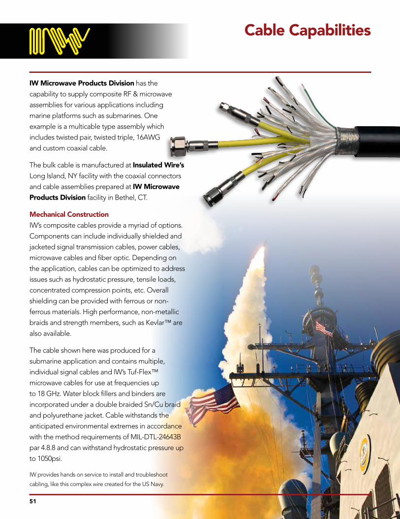
IW Microwave Products Division has the
capability to supply composite RF & microwave
assemblies for various applications including
marine platforms such as submarines . One
example is a multicable type assembly which
includes twisted pair, twisted triple, 16AWG
and custom coaxial cable .
The bulk cable is manufactured at Insulated Wire’s
Long Island, NY facility with the coaxial connectors
and cable assemblies prepared at IW Microwave
Products Division facility in Bethel, CT .
Mechanical Construction
IW’s composite cables provide a myriad of options .
Components can include individually shielded and
jacketed signal transmission cables, power cables,
microwave cables and fiber optic . Depending on
the application, cables can be optimized to address
issues such as hydrostatic pressure, tensile loads,
concentrated compression points, etc . Overall
shielding can be provided with ferrous or non-
ferrous materials . High performance, non-metallic
braids and strength members, such as Kevlar™ are
also available .
The cable shown here was produced for a
submarine application and contains multiple,
individual signal cables and IW’s Tuf-Flex™
microwave cables for use at frequencies up
to 18 GHz . Water block fillers and binders are
incorporated under a double braided Sn/Cu braid
and polyurethane jacket . Cable withstands the
anticipated environmental extremes in accordance
with the method requirements of MIL-DTL-24643B
par 4 .8 .8 and can withstand hydrostatic pressure up
to 1050psi .
IW provides hands on service to install and troubleshoot
cabling, like this complex wire created for the US Navy .
Cable Capabilities
51

The following contains a list of precautions and procedures that should be taken when handling or installing Insulated Wire cable assemblies. They should be used as guidelines and followed whenever possible. By doing this you can ensure a long assembly life which requires virtually no maintenance.
Handle cable with care: IW cable assemblies are designed to operate at the highest electrical performance level . High performance cables such as these require special handling procedures to ensure optimum electrical performance . Many of these handling procedures are outlined in detail, however taking just a few basic preventative measures during handling can significantly extend the life of the assembly . You should always take care to prevent anything from being placed on an assembly . This could result in internal damage caused by compression . Also, prevent the cable from bending below it’s minimum bend radius as this will cause the cable to kink, which results in internal damage and subsequent degradation in RF perfomance .
Limit bend radius whenever possible: Although IW cable assemblies can accommodate a very small bend radius, it is recommended to use the widest possible radius to fit the application . This will help to keep mechanical stresses low through the bend and prolong the life of the assembly .
Avoid torquing down connector ends until both connectors are mated in position: It is important to first hand tighten both connectors into position before any torque is applied . If a connector is torqued down before the assembly is routed into position, excessive torsion could be applied at the torqued connector’s termination during the routing . These torsion forces could cause the dielectric to change its mechanical position at the connector termination . This could ultimately lead to an electrical failure .
Avoid twisting assembly to orient connectors: When installing assemblies with right angle connectors, do not twist the cable or connectors
to orient with the mating connectors . Twisting the assembly could result in mechanically changing the dielectric position at the termination and ultimately lead to an electrical failure . Assemblies should be purchased with a specific connector offset angle to match the proper mating connector . If an offset angle needs to be changed during assembly installation, proper adjustment procedures can be obtained by calling IW’s Technical Support .
Avoid bending the assembly at the connector termination: A cable assembly should never be bent at the back of the connector . Applying a bend prematurely at the end of an assembly and allowing the bend to encompass the connector could lead to the build up of excessive cable forces against the connector and through the bend area . The applied forces will cause the cable to kink . Electrical degradation and possible failure may result .
Avoid pulling an assembly through channeling by the connector end: Never pull an assembly by its connector when routing it through a structure, channeling or building . Doing this could mechanically damage the connector termination . The assembly should always be pulled by the cable itself . Furthermore, the installation should be assisted by pushing the assembly through the channeling while the cable is pulled . Additionally, it is less stressful to the assembly if it is installed in phases (through individual sections) rather than a single run across the entire routing length .
Never allow an assembly to support its own weight when routed in a vertical installation: Never allow an assembly to hang freely by its own weight . Clamp down the cable at equal intervals along its length . Cable hangers can be used when it is not possible to clamp down the assembly in a vertical installation provided the assembly has been reinforced for such an installation . Using multiple hangers whenever possible is also recommended to help evenly distribute the assembly’s weight along the run .
Cable Handling
52

Avoid the use of cable ties: Most high performance cables use an air filled dielectric core . This makes the cable very soft . Therefore any compressive load applied to the cable has the potential of collapsing the dielectric core within the cable . Cable ties and tie wraps are not recommended for this reason . They offer virtually no load distribution and consequently focus very high compressive forces through the tied down area . A concentrated force such as this almost always deforms the cable and significantly degrades assembly performance . For best holding results with minimal clamping forces, IW recommends rubberized clamps . Be sure to select a clamp that will apply a minimum amount of compression force while still offering the desired holding strength . Selecting a clamp that it too small can do as much damage to an assembly as a cable tie .
Avoid subjecting the connector ends to cable axial loads: Cable assembly life can be increased by clamping down the cable a few inches from the connector ends in applications where the cable will be moving (such as a moving antenna) or where a high vibration condition exists . Clamping the cable down at the cable ends reduces mechanical loads applied to the connector when the cable is moved .
Always wrap connectors in weather proofing when installing outside: All cable connections that will be subjected to rain and snow should be wrapped in a weather proofing material . A self fusing silicone tape is recommend to create a weather tight seal over the connection . If weather precautions are not taken, water will eventually work its way into the connector assembly causing high insertion losses .
Always provide adequate drip loops: Always allow for a drip loop in outside applications to prevent water from flowing down the cable and onto the connector . Over time the water could work its way into the connector assembly causing high insertion losses .
Take extra care on short assemblies:
• Always bend assemblies around mandrels whenever possible .
• The use of mandrels or wheels will help to evenly distribute bending loads applied to the cable . This is the preferred method for bending cables .
• Take caution when bending cables by hand .
• Sometimes bending a cable by hand is the only option . In this case the following method should be used:
• Start at bending point keeping hands close together .
• Bend the cable a little at a time working in an outward direction along the bend .
• Return to the center point of the bend and work in an outward direction making the bend a little tighter .
• Continue to return to the center of the bend, and working outward until the desired bend is reached .
Take caution bending cables under 12” in length. An assembly that is 12” in length and smaller can be very rigid depending on the cable type . The cable becomes rigid because its inner and outer conductors are fully (mechanically) terminated to the cable connectors . The cable is terminated this way to yield maximum electrical performance . Unfortunately, it minimizes the bending characteristics of the assembly because the cable is too short to accommodate the total material volume displacement needed for a typical bend . Often, the minimum bend radius can not be achieved without damaging the assembly . Therefore, short cables should only be used in applications where slight jogging bends will be used . A longer assembly that uses a service loop should be considered as a replacement for a short cable in situation where a tight or sharp bend is needed .
Cable Handling
53

Aerospace
Sub-Surface
SatCom
Missiles
Ground Vehicles
High End Audio
Tactical Data Links
IFF Systems
CIWS
UAVs
Medical Electronics
ECMs
Geothermal Exploration
Instrumentation
High End Broadcast
Telecommunications
Markets Served
54

INSULATEDWIREINCORPORATED
Bulk Cable & Wire SalesInsulated Wire Inc.960 Sylvan Avenue, Bayport, NY 11705Tel: 631-472-4070 • Fax: 631 472 4071
Cable AssembliesIW Microwave Products Division2C Parklawn Drive, Bethel, CT 06801Tel: 203-791-1999 • Fax: 203 748 5217
Visit our website for contact information on your local representative at: www.iw-microwave.com/contact_usPlease don’t hesitate to contact IW directly if you are unable to locate a representative in your area.
AS9100 & ISO 9001: 2008 Certified
Copyright April, 2017