Contents Keylocks - NKK Switches · 2020-01-09 · F Series CK High Security Keylocks F4 Indicators...
25
F2 Contents Keylocks Indicators Accessories Supplement Tactiles Keylocks Rotaries Pushbuttons Illuminated PB Slides Programmable Rockers Touch Tilt A Toggles www.nkkswitches.com CK Series ........................................... F3 16mm & 19mm High Security 3A Power Level Solder Lug Bushing Mount SK Series ............................................ F9 12mm Low & Medium Security 3A & 1A Power Level Solder Lug Bushing Mount SK Series .......................................... F15 Antistatic Process Sealed Subminiature 0.4VA Logic Level Straight & Right Angle PC PCB Mount SK Series .......................................... F19 Process Sealed 0.4VA Logic Level Straight & Right Angle PC PCB Mount SK Series .......................................... F25 Antistatic Snap-in 0.4VA Logic Level Solder Lug Snap-in Mount
Transcript of Contents Keylocks - NKK Switches · 2020-01-09 · F Series CK High Security Keylocks F4 Indicators...
F2
Contents Keylocks In
dica
tors
Acc
esso
ries
Supp
lem
ent
Tact
iles
Key
lock
sRo
tari
esPu
shbu
ttons
Illum
inat
ed P
BSl
ides
Prog
ram
mab
leRo
cker
sTo
uch
Tilt
A
Togg
les
www.nkkswitches.com
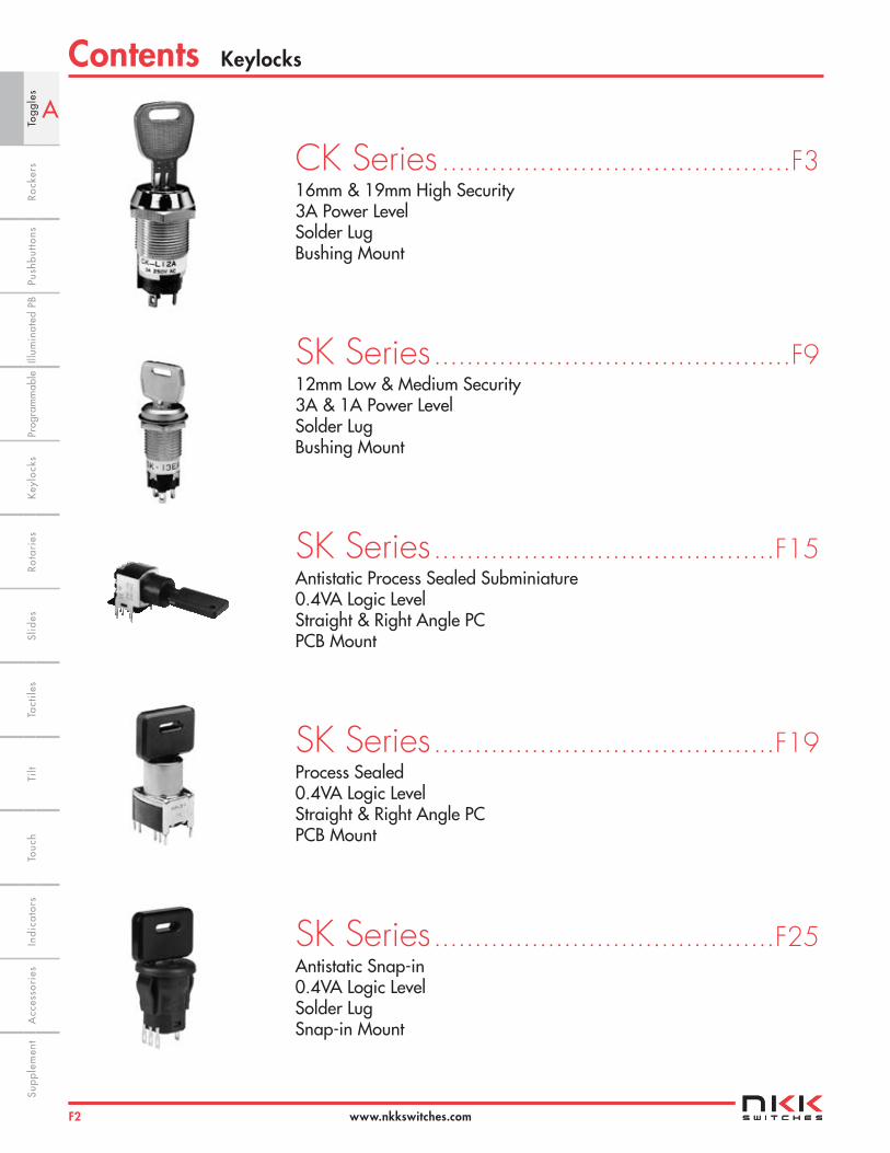
CK Series ...........................................F316mm & 19mm High Security3A Power Level Solder Lug Bushing Mount
SK Series ............................................F912mm Low & Medium Security 3A & 1A Power Level Solder LugBushing Mount
SK Series ..........................................F15Antistatic Process Sealed Subminiature 0.4VA Logic LevelStraight & Right Angle PC PCB Mount
SK Series ..........................................F19Process Sealed 0.4VA Logic Level Straight & Right Angle PCPCB Mount
SK Series ..........................................F25Antistatic Snap-in0.4VA Logic Level Solder LugSnap-in Mount
F
Series CKHigh Security Keylocks
F3
Indi
cato
rsA
cces
sori
esSu
pple
men
tTa
ctile
sK
eylo
cks
Rota
ries
Push
butto
nsIll
umin
ated
PB
Slid
esPr
ogra
mm
able
Touc
hTi
ltTo
ggle
sRo
cker
s
www.nkkswitches.com
Electrical Capacity (Resistive Load) Power Level: 3A @ 250V AC
Other Ratings Contact Resistance: 20 milliohms maximum Insulation Resistance: 1,000 megohms minimum @ 500V DC Dielectric Strength: 1,000V AC minimum between contacts for 1 minute minimum; 1,500V AC minimum between contacts & case for 1 minute minimum Mechanical Life: 30,000 cycles minimum Electrical Life: 10,000 cycles minimum Static Capability: Withstands 15 kilovolts minimum ESD minimum (for CKM models only)
Nominal Operating Torque: 16mm Bushing (CKM models): .04 mNm (5.67 oz•in) for Flat Key .08 mNm (11.33 oz•in) for Tubular Key 19mm Bushing (CKL models): .05 mNm (7.08 oz•in) for Flat Key .07 mNm (9.91 oz•in) for Tubular Key Contact Timing: Break-before-make Angle of Throw: 90° for 2-position & 45° for 3-position
Materials & Finishes Keys for CKM: Brass with nickel plating with ABS handle Keys for CKL: Brass with nickel plating for tubular key; brass with chrome plating for flat key Housing/Bushing: Glass fiber reinforced PBT for CKM models; zinc alloy with chrome plating for CKL Base: LCP (Liquid Crystal Polymer) Contact Terminals: Copper with silver plating Common Terminals: Copper with silver plating Movable Contactor: Copper Movable Contacts: Silver
Environmental Data Operating Temperature Range: –25°C through +70°C (–13°F through +158°F) Humidity: 90 ~ 95% humidity for 240 hours @ 40°C (104°F) for CKM; 90 ~ 95% humidity for 96 hours @ 40°C (104°F) for CKL Vibration: 10 ~ 55Hz with peak-to-peak amplitude of 1.5mm for CKM or 0.7mm for CKL traversing the frequency range & returning in 1 minute; 3 right angled directions for 2 hours Shock: 50G (490m/s2) acceleration for CKM; 30G (294m/s2) acceleration for CKL; (CKM & CKL tested in 6 right angled directions, with 5 shocks in each direction)
Installation Mounting Torque: 1.5 Nm (13.28 lb•in) maximum Soldering Time & Temperature: Manual Soldering: See Profile A in Supplement section.
General Specifications
F
Series CK High Security Keylocks
F4
Indi
cato
rsA
cces
sori
esSu
pple
men
tTa
ctile
sK
eylo
cks
Rota
ries
Push
butto
nsIll
umin
ated
PB
Slid
esPr
ogra
mm
able
Touc
hTi
lt Ro
cker
sTo
ggle
s
www.nkkswitches.com
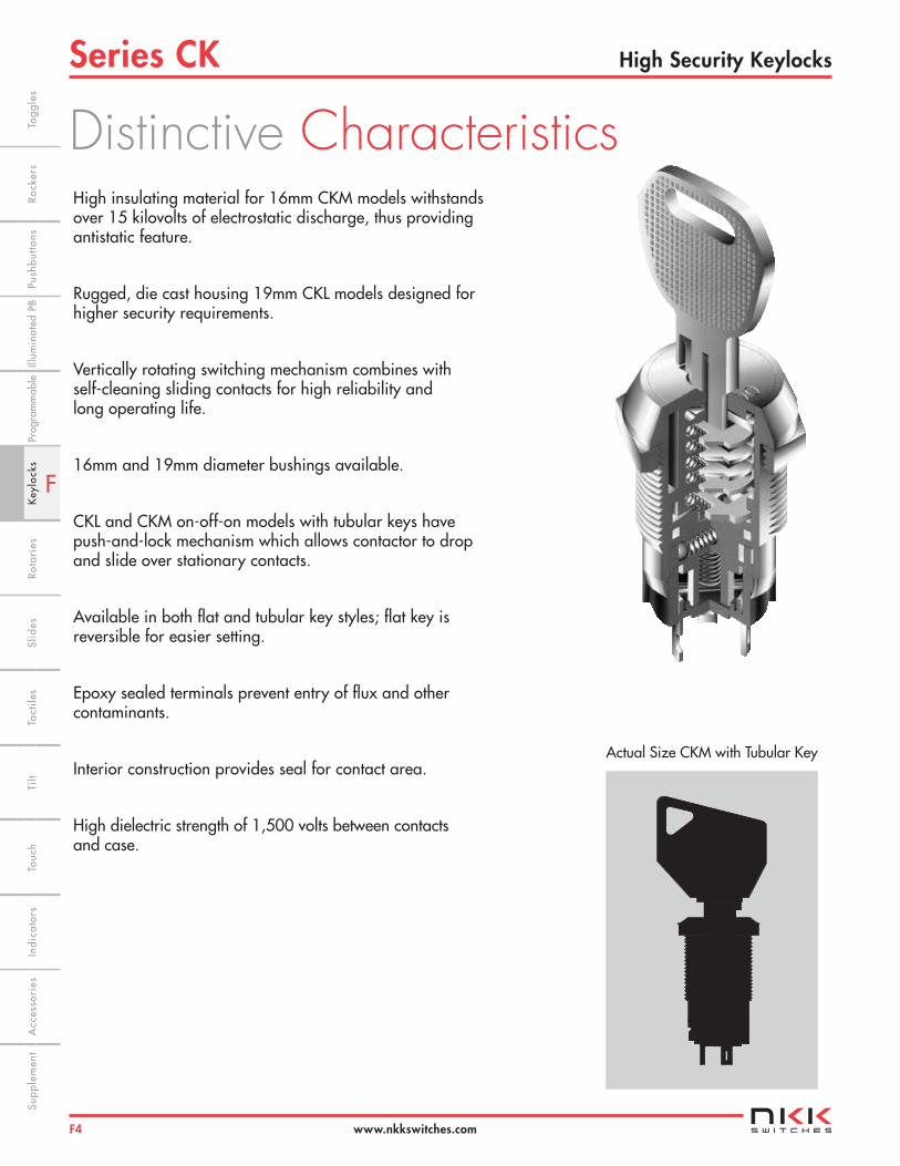
High insulating material for 16mm CKM models withstands over 15 kilovolts of electrostatic discharge, thus providing antistatic feature.
Rugged, die cast housing 19mm CKL models designed for higher security requirements.
Vertically rotating switching mechanism combines with self-cleaning sliding contacts for high reliability and long operating life.
16mm and 19mm diameter bushings available.
CKL and CKM on-off-on models with tubular keys have push-and-lock mechanism which allows contactor to drop and slide over stationary contacts.
Available in both flat and tubular key styles; flat key is reversible for easier setting.
Epoxy sealed terminals prevent entry of flux and other contaminants.
Interior construction provides seal for contact area.
High dielectric strength of 1,500 volts between contacts and case.
Actual Size CKM with Tubular Key
Distinctive Characteristics

F
Series CKHigh Security Keylocks
F5
Indi
cato
rsA
cces
sori
esSu
pple
men
tTa
ctile
sK
eylo
cks
Rota
ries
Push
butto
nsIll
umin
ated
PB
Slid
esPr
ogra
mm
able
Touc
hTi
ltTo
ggle
sRo
cker
s
www.nkkswitches.com
BushingsM 16mm Diameter
L 19mm Diameter
TYPICAL SWITCH ORDERING EXAMPLE
One key supplied with each switch
16mm Diameter Bushing
Silver Contacts Rated 3A @ 250V AC
SPDT ON-NONE-ON Circuit Key Removable in Positions 1 and 3
Solder Lug Terminals
DESCRIPTION FOR TYPICAL ORDERING EXAMPLE
CKM12AFW01
Circuits & Key-Removable PositionsCode Pos. 1 Pos. 2 Pos. 3 Key Removes
2A ON NONE ON Positions 1 and 3
2B ON NONE ON Position 1
3E ON OFF ON Position 2
Contact Material
W Silver Rated 3A @ 250V AC
MCK 2A1 F W 01
KeysF Flat
T Tubular
Poles1 SPDT
Terminals01 Solder Lug

F
Series CK High Security Keylocks
F6
Indi
cato
rsA
cces
sori
esSu
pple
men
tTa
ctile
sK
eylo
cks
Rota
ries
Push
butto
nsIll
umin
ated
PB
Slid
esPr
ogra
mm
able
Touc
hTi
lt Ro
cker
sTo
ggle
s
www.nkkswitches.com
KEYS
CONTACT MATERIALS, RATINGS & TERMINALS
Pole & Throw Model
Key Positions
Pos 1 Pos 2 Pos 3
Connected Terminals (Terminal numbers are on switch) Pos 1 Pos 2 Pos 3 Schematic
= Key Removable = Not Removable = Maximum Arc
SPDT CKM12A CKL12A ON NONE ON COM-1 ____ COM-2
SPDT CKM12B CKL12B ON NONE ON COM-1 ____ COM-2
SPDT CKM13E CKL13E ON OFF ON COM-1 OPEN COM-2
Solder Lug Terminalfor CKM
Flat KeyTubular Key(must be pressed inward to actuate)
POLES, CIRCUITS & KEY-REMOVABLE POSITIONS
Silver over SilverPower Level 3A @ 250V AC
Solder Lug TerminalsSolder Lug Terminal
for CKL
F T
W
01
1 2
COM
1 2
COM
OP
EN
POS 1
3
POS 1
3
AT4147 for CKM 16mm Brass with Nickel Plating key base & ABS key handleAT4153 for CKL 19mm Brass with Chrome Plating (crosshatch texture on handle)
One key provided with each switch (no master key available)For ordering additional keys, indicate the same keynumber that is engraved on the face of your switch.
Randomly assigned key number (001 through 010 for CKMmodels & 001 through 025 for CKL models).
Typical Key Ordering Example: AT4153-001
AT4146 for CKM 16mm Brass with Nickel Plating key base & ABS key handleAT4152 for CKL 19mm Brass with Nickel Plating (smooth)
One key provided with each switch (no master key available) For ordering additional keys, indicate the same key number that is engraved on the face of your switch.
Randomly assigned key number (001 through 025 for CKMmodels & 001 through 050 for CKL models).
Typical Key Ordering Example: AT4146-001
(22.3).878
(49.3)1.941
(20.0).787
(1.8).071
(22.5).886
(35.5)1.398(9.6) Dia
.378
(19.0).748
(1.5).059
AT4153
(40.8)1.606
(20.0).787
(3.5).138
(20.0).787AT4147 (26.0)
1.024
(25.0).984
(33.5)1.319
(3.5).138
(7.0) Dia.276
(10.5) Dia .413
AT4152
AT4146
Thk = (0.8) .031
(5.5).217
(2.8).110
(3.1).122 (1.4)
.055
Epoxy Seal(5.0).197
(2.4).094
(2.7).106
(1.2).047
Epoxy Seal
Thk = (0.8) .031
•
POS 1
2
3
F
Series CKHigh Security Keylocks
F7
Indi
cato
rsA
cces
sori
esSu
pple
men
tTa
ctile
sK
eylo
cks
Rota
ries
Push
butto
nsIll
umin
ated
PB
Slid
esPr
ogra
mm
able
Touc
hTi
ltTo
ggle
sRo
cker
s
www.nkkswitches.com
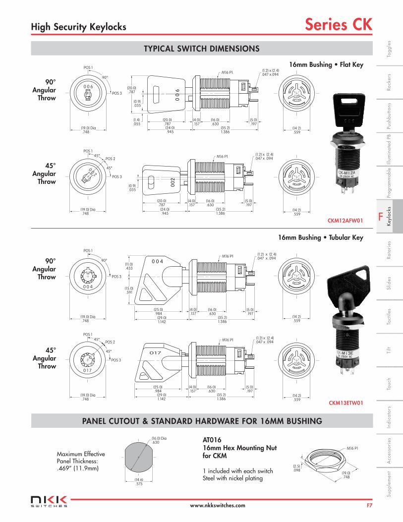
TYPICAL SWITCH DIMENSIONS
16mm Bushing • Flat Key
16mm Bushing • Tubular Key
CKM12AFW01
PANEL CUTOUT & STANDARD HARDWARE FOR 16MM BUSHING
Maximum Effective Panel Thickness: .469” (11.9mm)
AT016 16mm Hex Mounting Nutfor CKM 1 included with each switch Steel with nickel plating
(19.0).748
(2.5).098
M16 P1
90°Angular
Throw
45°Angular
Throw
90°Angular
Throw
45°Angular
Throw
M16 P1 (1.2) x (2.4).047 x.094
(5.0).197
(16.0).630
(4.0).157
(20.0).787(24.0).945
(35.2)1.386
00
6(20.0).787
(0.9).035
(1.4).055
0 0 6
90°
POS 1
POS 3
(19.0) Dia .748
M16 P1 (1.2) x (2.4).047 x .094
(5.0).197
(16.0).630
(4.0).157
(20.0).787
(24.0).945
(35.2)1.386
00
2
(0.9).035
0 0 2
POS 1
POS 3
(19.0) Dia .748
POS 245°
45°
0 1 7
POS 1
POS 3
(19.0) Dia .748
POS 245°
45°
M16 P1 (1.2) x (2.4).047 x .094
(5.0).197
(16.0).630
(4.0).157
(25.0).984
(29.0)1.142
(35.2)1.386
017
0 0 4
POS 1
POS 3
(19.0) Dia .748
90°M16 P1 (1.2) x (2.4)
.047 x .094
(5.0).197
(16.0).630
(4.0).157
(25.0).984
(29.0)1.142
(35.2)1.386
(15.0).591
(11.0).433
0 0 4
C O M
12
(14.2).559
C O M
12
(14.2).559
C O M
12
(14.2).559
C O M
12
(14.2).559
(16.0) Dia.630
(14.6).575
CKM13ETW01

F
Series CK High Security Keylocks
F8
Indi
cato
rsA
cces
sori
esSu
pple
men
tTa
ctile
sK
eylo
cks
Rota
ries
Push
butto
nsIll
umin
ated
PB
Slid
esPr
ogra
mm
able
Touc
hTi
lt Ro
cker
sTo
ggle
s
www.nkkswitches.com
0 0 5
90°
POS 1
POS 3
(22.0) Dia .866
0 1 5
45°POS 1
POS 3
(22.0) Dia .866
POS 2
45°
0 4 2
POS 1
POS 2
(22.0) Dia .866
POS 3
45°
45°
0 0 8
POS 1
(22.0) Dia .866
POS 3
90°
TYPICAL SWITCH DIMENSIONS
19mm Bushing • Flat Key
19mm Bushing • Tubular Key
CKL12AFW01
CKL13ETW01
90°Angular
Throw
45°Angular
Throw
(40.0)1.575
(29.8)1.173
00
5
M19 P1 (1.4) x (2.8).055 x .110
(5.5).217
(17.0).669
(5.4).213
(0.7).028
(22.3).878
(1.0).039
(20.0).787
(40.0)1.575
(29.8)1.173
M19 P1 (1.4) x (2.8).055 x .110
(5.5).217
(17.0).669
(5.4).213
015
(0.7).028
(40.0)1.575
(30.5)1.201
M19 P1 (1.4) x (2.8).055 x .110
(5.5).217
(17.0).669
(5.4).213
(22.5).886
(40.0)1.575
(30.5)1.201
M19 P1 (1.4) x (2.8).055 x .110
(5.5).217
(17.0).669
(5.4).213
(22.5).886
0 0 8
(19.0).748
C O M
12
(16.8).661
PANEL CUTOUT & STANDARD HARDWARE FOR 19MM BUSHING
Maximum Effective Panel Thickness: .496” (12.6mm)
AT019 19mm Hex Mounting Nutfor CKL 1 included with each switch Steel with nickel plating (22.0)
.866
(3.4).134
M19 P1
90°Angular
Throw
45°Angular
Throw
C O M
12
(16.8).661
C O M
12
(16.8).661
C O M
12
(16.8).661
(19.0) Dia.748
(17.2).677

F
Series SKLow & Medium Security Keylocks
F9
Indi
cato
rsA
cces
sori
esSu
pple
men
tTa
ctile
sK
eylo
cks
Rota
ries
Push
butto
nsIll
umin
ated
PB
Slid
esPr
ogra
mm
able
Touc
hTi
ltTo
ggle
sRo
cker
s
www.nkkswitches.com
Electrical Capacity (Resistive Load) Power Level (silver): 3A @ 125V AC for low & medium security; 1A @ 250V AC for low security
Other Ratings Contact Resistance: 10 milliohms maximum Insulation Resistance: 1,000 megohms minimum @ 500V DC Dielectric Strength: 1,000V AC minimum between contacts for 1 minute minimum; 1,500V AC minimum between contacts & case for 1 minute minimum Mechanical Life: 30,000 cycles minimum Electrical Life: 10,000 cycles minimum Nominal Operating Torque: .026Nm (.234 lb•in) for low & medium security Contact Timing: Break-before-make Angle of Throw: 90° for 2-position & 45° for 3-position
Materials & Finishes Key: Zinc alloy with chrome plating (matte) for low security models; brass with nickel plating (shiny) for medium security models Tumbler Barrel: Zinc alloy with chrome plating (matte) for low security models; zinc alloy with chrome plating (shiny) for medium security models Housing/Bushing: Zinc alloy with chrome plating (matte) for low security models; zinc alloy with chrome plating (shiny) for medium security models Base: Phenolic resin (thermoset) Movable Contactor: Silver Stationary Contacts: Silver capped copper with silver plating Terminals: Copper or brass with silver plating
Environmental Data Operating Temperature Range: –25°C through +70°C (–13°F through +158°F) Humidity: 90 ~ 95% humidity for 96 hours @ 40°C (104°F) Vibration: 10 ~ 55Hz with peak-to-peak amplitude of 1.5mm traversing the frequency range & returning in 1 minute; 3 right angled directions for 2 hours Shock: 50G (490m/s2) acceleration (tested in 6 right angled directions, with 5 shocks in each direction)
Installation Mounting Torque: 1.5Nm (13.28 lb•in) maximum Soldering Time & Temperature: Manual Soldering: See Profile A in Supplement section.
Standards & Certifications UL: File No. E44145 - Recognized only when ordered with marking on switch. Add “/U” or “/CUL” to end of part number to order UL recognized switch. All low security models recognized at 3A @ 125V AC or 1A @ 250V AC & all medium security models recognized at 3A @ 125V AC CSA: File No. 023535_0_000 - Certified only when ordered with marking on switch. Add “/C” to end of part number to order CSA certified switch. All low security models certified at 3A @ 125V AC or 1A @ 250V AC
General Specifications

F
Series SK Low & Medium Security Keylocks
F10
Indi
cato
rsA
cces
sori
esSu
pple
men
tTa
ctile
sK
eylo
cks
Rota
ries
Push
butto
nsIll
umin
ated
PB
Slid
esPr
ogra
mm
able
Touc
hTi
lt Ro
cker
sTo
ggle
s
www.nkkswitches.com
12mm diameter bushing for easy panel cutout preparation and high density mounting.
Epoxy sealed terminals prevent entry of flux and other contaminants.
Short behind panel dimension - only 1.063” (27.0mm).
High dielectric strength of 1,500 volts between contacts and case.
Detent mechanism gives crisp, positive action for accurate switch setting.
Dust resistant interior construction protects contacts.
Actual Size
Distinctive Characteristics

F
Series SKLow & Medium Security Keylocks
F11
Indi
cato
rsA
cces
sori
esSu
pple
men
tTa
ctile
sK
eylo
cks
Rota
ries
Push
butto
nsIll
umin
ated
PB
Slid
esPr
ogra
mm
able
Touc
hTi
ltTo
ggle
sRo
cker
s
www.nkkswitches.com
TYPICAL SWITCH ORDERING EXAMPLE
Silver Contacts Rated 3A @ 125V AC
Low Security Lock Mechanism
2 keys supplied with each switch
Solder Lug Terminals
SPDT ON-NONE-ON Circuit Key Removable in
Position 1
DESCRIPTION FOR TYPICAL ORDERING EXAMPLE
SK12BAW01
Terminals01 Solder Lug
Circuits & Key-Removable PositionsCode Pos. 1 Pos. 2 Pos. 3 Key Removes
2A ON NONE ON Positions 1 and 3
2B ON NONE ON Position 1
3D ON OFF ON Positions 1, 2, 3
3E ON OFF ON Position 2
Contact Material
W Silver Rated 3A @ 125V AC
SK 2B1 A W 01
Lock MechanismsA Low Security
DMedium Security (not combinable with code 3D circuit)
Poles1 SPDT
IMPORTANT: Switches are supplied without UL, cULus & CSA marking unless specified.UL, cULus & CSA recognized only when ordered with marking on the switch.Specific models, ratings, & ordering instructions are noted on the General Specifications page.
F
Series SK Low & Medium Security Keylocks
F12
Indi
cato
rsA
cces
sori
esSu
pple
men
tTa
ctile
sK
eylo
cks
Rota
ries
Push
butto
nsIll
umin
ated
PB
Slid
esPr
ogra
mm
able
Touc
hTi
lt Ro
cker
sTo
ggle
s
www.nkkswitches.com
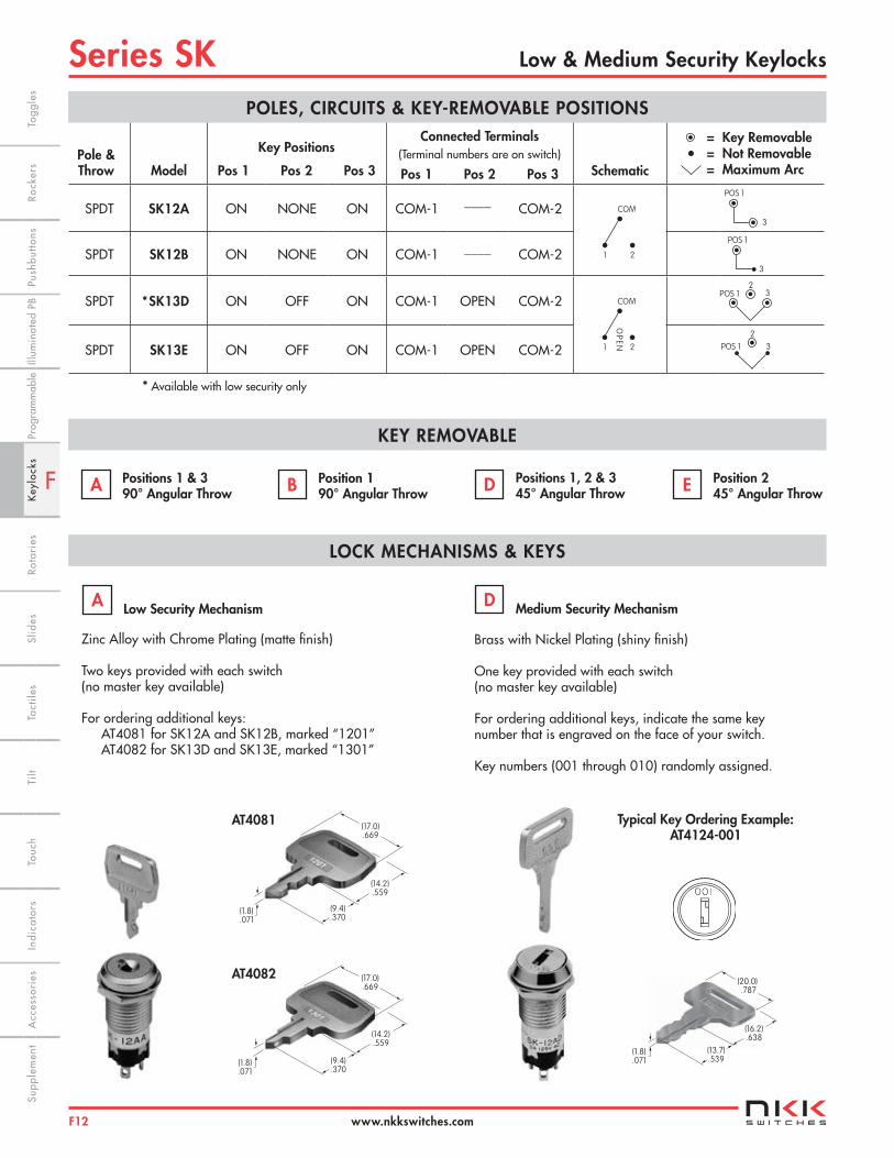
KEY REMOVABLE
Pole & Throw Model
Key Positions
Pos 1 Pos 2 Pos 3
Connected Terminals (Terminal numbers are on switch) Pos 1 Pos 2 Pos 3 Schematic
= Key Removable = Not Removable = Maximum Arc
SPDT SK12A ON NONE ON COM-1 ____ COM-2
SPDT SK12B ON NONE ON COM-1 ____ COM-2
SPDT *SK13D ON OFF ON COM-1 OPEN COM-2
SPDT SK13E ON OFF ON COM-1 OPEN COM-2
Positions 1 & 3 90° Angular Throw
POLES, CIRCUITS & KEY-REMOVABLE POSITIONS
A
1 2
COM
1 2
COM
OP
EN
POS 1
3
POS 1
3
Zinc Alloy with Chrome Plating (matte finish) Two keys provided with each switch (no master key available)
For ordering additional keys:AT4081 for SK12A and SK12B, marked “1201” AT4082 for SK13D and SK13E, marked “1301”
Brass with Nickel Plating (shiny finish)
One key provided with each switch (no master key available)
For ordering additional keys, indicate the same keynumber that is engraved on the face of your switch.
Key numbers (001 through 010) randomly assigned.
•
POS 1
2
3
POS 12
3
Position 1 90° Angular Throw B Positions 1, 2 & 3
45° Angular Throw D Position 2 45° Angular Throw E
* Available with low security only
LOCK MECHANISMS & KEYS
Low Security MechanismA
Medium Security MechanismD
Typical Key Ordering Example: AT4124-001
(17.0).669
(14.2).559
(9.4).370
(1.8).071
(17.0).669
(14.2).559
(9.4).370
(1.8).071
(13.7).539
(16.2).638
(20.0) .787
(1.8).071
AT4082
AT4081

F
Series SKLow & Medium Security Keylocks
F13
Indi
cato
rsA
cces
sori
esSu
pple
men
tTa
ctile
sK
eylo
cks
Rota
ries
Push
butto
nsIll
umin
ated
PB
Slid
esPr
ogra
mm
able
Touc
hTi
ltTo
ggle
sRo
cker
s
www.nkkswitches.com
TYPICAL SWITCH DIMENSIONS
Low Security • 90° Angular Throw
Low Security • 45° Angular Throw
SK12BAW01
SK13EAW01
CONTACT MATERIALS, RATINGS, & TERMINALS
Silver over Silver Power Level 3A @ 125V AC
Solder Lug Terminals
W
01
(2.0).079
Epoxy Seal(4.5).177
(2.0).079
(1.1).043
Thk = (0.8).031
POS 1
90°
POS 3
(14.0) Dia .551
M12 P1
(13.0).512
(4.5).177
(30.0)1.181
(3.0).118
(13.2).520
(0.5).020
(17.0).669
(1.1) x (2.0) Typ.043 x .079
(0.8) Typ.031
(2.0) Typ.079
21
CO
M
(10.8).425
2
1
CO
M
(10.8).425
(13.2).520
M12 P1
(13.0).512
(4.5).177
(30.0)1.181
(3.0).118
(0.5).020
(17.0).669
(1.1) x (2.0) Typ.043 x .079
(2.0) Typ.079
(0.8) Typ.031
(14.0) Dia .551
POS 2
POS 3POS 1
45° 45°
F
Series SK Low & Medium Security Keylocks
F14
Indi
cato
rsA
cces
sori
esSu
pple
men
tTa
ctile
sK
eylo
cks
Rota
ries
Push
butto
nsIll
umin
ated
PB
Slid
esPr
ogra
mm
able
Touc
hTi
lt Ro
cker
sTo
ggle
s
www.nkkswitches.com
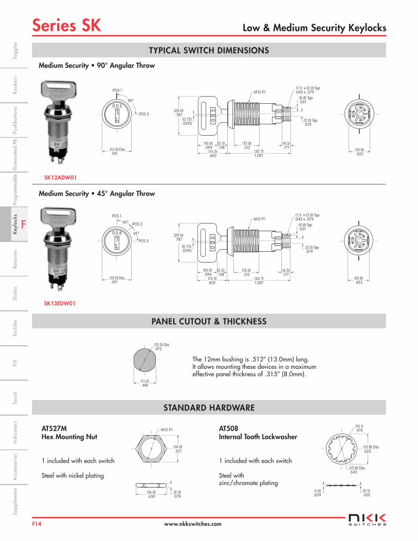
TYPICAL SWITCH DIMENSIONS
Medium Security • 90° Angular Throw
Medium Security • 45° Angular Throw
SK12ADW01
SK13EDW01
PANEL CUTOUT & THICKNESS
AT508 Internal Tooth Lockwasher 1 included with each switch Steel with zinc/chromate plating
21
CO
M
(10.8).425
0 0
5
(2.0) Typ.079
(0.8) Typ.031
(1.1) x (2.0) Typ.043 x .079
(4.5).177
M12 P1
(20.0).787
(0.75).0295
(10.0).394
(3.5).138
(15.3).602
(32.7)1.287
(13.0).512
POS 1
90°
POS 3
(15.0) Dia .591
0 0 5
21
CO
M
(10.8).425
0 0
6
(2.0) Typ.079
(0.8) Typ.031
(1.1) x (2.0) Typ.043 x .079
(4.5).177
M12 P1
(20.0).787
(0.75).0295
(10.0).394
(3.5).138
(15.3).602
(32.7)1.287
(13.0).512
0 0 6
(15.0) Dia .591
POS 2
POS 3
POS 1
45°
45°
(12.0) Dia.472
(11.2).441
The 12mm bushing is .512” (13.0mm) long. It allows mounting these devices in a maximum effective panel thickness of .315” (8.0mm).
STANDARD HARDWARE
AT527M Hex Mounting Nut 1 included with each switch Steel with nickel plating
M12 P1
(14.0).551
(16.0).630
(2.0).079
(0.5).020
(1.0).039
(12.1).476
(15.8) Dia.622
(13.8) Dia.543
F
Series SKAntistatic Process Sealed Keylocks
F15
Indi
cato
rsA
cces
sori
esSu
pple
men
tTa
ctile
sK
eylo
cks
Rota
ries
Push
butto
nsIll
umin
ated
PB
Slid
esPr
ogra
mm
able
Touc
hTi
ltTo
ggle
sRo
cker
s
www.nkkswitches.com
Electrical Capacity (Resistive Load) Logic Level: 0.4VA maximum @ 28V AC/DC maximum (Applicable Range 0.1mA ~ 0.1A @ 20mV ~ 28V) Note: Find additional explanation of operating range in Supplement section
Other Ratings Contact Resistance: 100 milliohms maximum Insulation Resistance: 100 megohms minimum @ 500V DC Dielectric Strength: 500V AC minimum for 1 minute minimum Mechanical Life: 30,000 cycles minimum Electrical Life: 20,000 cycles minimum Static Capability: Withstands 15 kilovolts ESD Nominal Operating Torque: .0002Nm (.0017 lb•in) Contact Timing: Break-before-make Angle of Throw: 45° for 3-position & 5-position
Materials & Finishes Key: Polyacetal Housing/Bushing: Glass fiber reinforced polyester (PBT) Base: Glass fiber reinforced polyamide Rotor & Stopper: Polyacetal Tumbler Plate: Brass Movable Contactor: Beryllium copper with gold plating Stationary Contacts: Phosphor bronze with gold plating Terminals: Phosphor bronze with gold plating Mounting Bracket: Steel with tin plating
Environmental Data Operating Temperature Range: –25°C through +70°C (–13°F through +158°F) Humidity: 90 ~ 95% humidity for 240 hours @ 40°C (104°F) Vibration: 10 ~ 55Hz with peak-to-peak amplitude of 1.5mm traversing the frequency range & returning in 1 minute; 3 right angled directions for 2 hours Shock: 50G (490m/s2) acceleration (tested in 6 right angled directions, with 5 shocks in each direction)
PCB Processing Soldering: Wave Soldering Recommended. See Profile A in Supplement section. Manual Soldering: See Profile A in Supplement section. Cleaning: Automated cleaning. See Cleaning specifications in Supplement section.
Standards & Certifications The SK Series devices have not been tested for UL recognition or CSA certification. These switches are designed for use in a low-voltage, low-current, logic-level circuit. When used as intended in a logic-level circuit, the results do not produce hazardous energy.
General Specifications
F
Series SK Antistatic Process Sealed Keylocks
F16
Indi
cato
rsA
cces
sori
esSu
pple
men
tTa
ctile
sK
eylo
cks
Rota
ries
Push
butto
nsIll
umin
ated
PB
Slid
esPr
ogra
mm
able
Touc
hTi
lt Ro
cker
sTo
ggle
s
www.nkkswitches.com
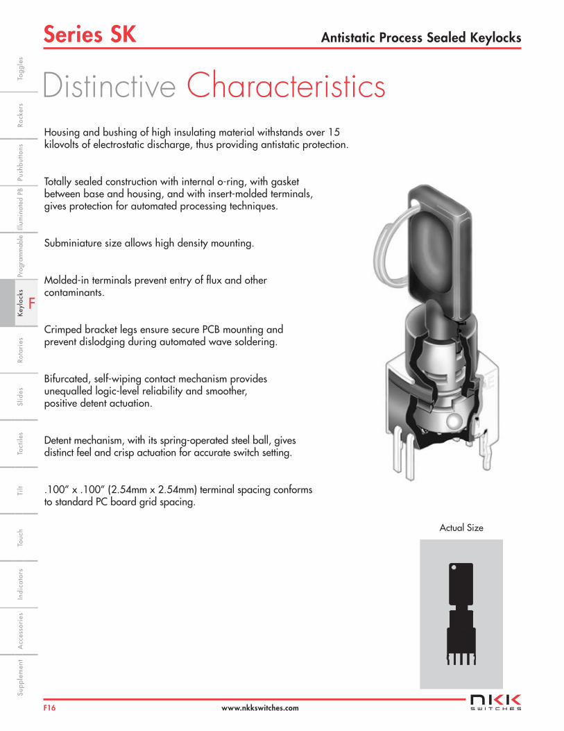
Housing and bushing of high insulating material withstands over 15 kilovolts of electrostatic discharge, thus providing antistatic protection.
Totally sealed construction with internal o-ring, with gasket between base and housing, and with insert-molded terminals, gives protection for automated processing techniques.
Subminiature size allows high density mounting.
Molded-in terminals prevent entry of flux and other contaminants.
Crimped bracket legs ensure secure PCB mounting and prevent dislodging during automated wave soldering.
Bifurcated, self-wiping contact mechanism provides unequalled logic-level reliability and smoother, positive detent actuation.
Detent mechanism, with its spring-operated steel ball, gives distinct feel and crisp actuation for accurate switch setting.
.100” x .100” (2.54mm x 2.54mm) terminal spacing conforms to standard PC board grid spacing.
Actual Size
Distinctive Characteristics
F
Series SKAntistatic Process Sealed Keylocks
F17
Indi
cato
rsA
cces
sori
esSu
pple
men
tTa
ctile
sK
eylo
cks
Rota
ries
Push
butto
nsIll
umin
ated
PB
Slid
esPr
ogra
mm
able
Touc
hTi
ltTo
ggle
sRo
cker
s
www.nkkswitches.com
TYPICAL SWITCH ORDERING EXAMPLE
DESCRIPTION FOR TYPICAL ORDERING EXAMPLE
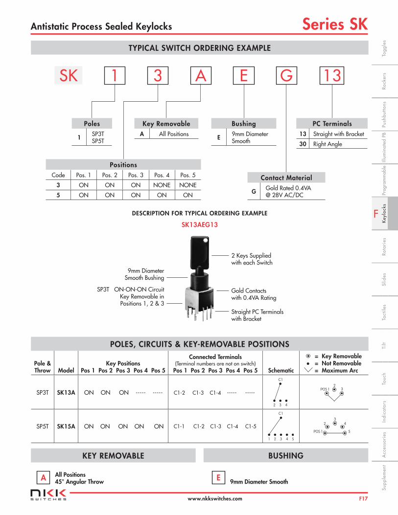
SK13AEG13
PC Terminals13 Straight with Bracket
30 Right Angle
PositionsCode Pos. 1 Pos. 2 Pos. 3 Pos. 4 Pos. 5
3 ON ON ON NONE NONE
5 ON ON ON ON ON
Contact Material
G Gold Rated 0.4VA @ 28V AC/DC
SK 1 A 13
Poles
1 SP3TSP5T
3 E G
Bushing
E 9mm Diameter Smooth
Key RemovableA All Positions
2 Keys Suppliedwith each Switch
Gold Contacts with 0.4VA Rating
Straight PC Terminals with Bracket
9mm Diameter Smooth Bushing
SP3T ON-ON-ON Circuit Key Removable in Positions 1, 2 & 3
KEY REMOVABLE
Pole & Throw Model
Key Positions Pos 1 Pos 2 Pos 3 Pos 4 Pos 5
Connected Terminals (Terminal numbers are not on switch)
Pos 1 Pos 2 Pos 3 Pos 4 Pos 5 Schematic
= Key Removable = Not Removable = Maximum Arc
SP3T SK13A ON ON ON ----- ----- C1-2 C1-3 C1-4 ----- -----
SP5T SK15A ON ON ON ON ON C1-1 C1-2 C1-3 C1-4 C1-5
All Positions 45° Angular Throw
POLES, CIRCUITS & KEY-REMOVABLE POSITIONS
A
•
9mm Diameter Smooth E
1 2 3
C1
4 5
POS 12
3
POS 1
23
4
5
BUSHING
2 3
C1
4
F
Series SK Antistatic Process Sealed Keylocks
F18
Indi
cato
rsA
cces
sori
esSu
pple
men
tTa
ctile
sK
eylo
cks
Rota
ries
Push
butto
nsIll
umin
ated
PB
Slid
esPr
ogra
mm
able
Touc
hTi
lt Ro
cker
sTo
ggle
s
www.nkkswitches.com
KEY
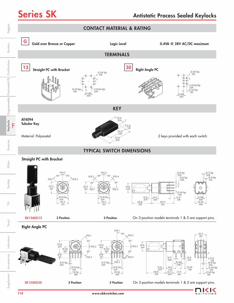
AT4094 Tubular Key Material: Polyacetal
CONTACT MATERIAL & RATING
Gold over Bronze or Copper Logic Level 0.4VA @ 28V AC/DC maximum G
TERMINALS
Straight PC with Bracket 13 Right Angle PC 30
(5.08).200
(2.54) Typ .100
(2.54) Typ .100
(1.0) Dia Typ.039
1
C
5 4
3
2
(2.54) Typ .100
(2.54) Typ .100
(1.0) Dia Typ.039
(5.08).200
4
3
2
5
C
1
2 keys provided with each switch(21.6).850
(16.0).630
(3.0).118
(9.0).354
TYPICAL SWITCH DIMENSIONS
Straight PC with Bracket
Right Angle PC
SK13AEG13 3 Position 5 Position On 3-position models terminals 1 & 5 are support pins.
SK15AEG30 3 Position 5 Position On 3-position models terminals 1 & 5 are support pins.
(10.7).421
(9.0) Dia.354
POS 2
POS 1 POS 3
(10.7).421
45°45°
(10.7).421
POS 2
POS 1
POS 3
POS 4
POS 5(10.7).421
(9.0) Dia.354
45°45°
45°45°
(3.5).138
(6.7).264
(2.0).079
(20.7).815
(18.0).709
(9.0).354
(0.5) Typ.020
(0.6) Typ.024
(2.54) Typ .100
23
4
1C
5
(10.16).400
(5.08).200
(0.7) Typ.028
(0.3) Typ.012
1 5C
2 3 4
(10.7).421
(3.5).138
(0.6) Typ .024(2.54) Typ .100
(2.54) Typ .100
POS 2
POS 1
POS 3(12.0).472
POS 4
POS 5
(6.65).262
(4.0).157
(10.16).400
(0.5) Typ.020
(9.0) Dia.354
45°
45°
45°
45° (0.7).028
(6.7).264
(2.0).079
(18.0).709
(9.0).354
(11.7).461
(0.3).012
(9.5).374
(5.08).200
(2.54).100
POS 2
POS 1
POS 3
(12.0).472
(6.65).262
(4.0).157
(10.16).400
(0.5) Typ.020
(9.0) Dia.354
45°
45°

F
Series SKProcess Sealed Keylocks
F19
Indi
cato
rsA
cces
sori
esSu
pple
men
tTa
ctile
sK
eylo
cks
Rota
ries
Push
butto
nsIll
umin
ated
PB
Slid
esPr
ogra
mm
able
Touc
hTi
ltTo
ggle
sRo
cker
s
www.nkkswitches.com
Electrical Capacity (Resistive Load) Logic Level: 0.4VA maximum @ 28V AC/DC maximum (Applicable Range 0.1mA ~ 0.1A @ 20mV ~ 28V) See Supplement section to find explanation of operating range
Other Ratings Contact Resistance: 80 milliohms maximum Insulation Resistance: 100 megohms minimum @ 500V DC Dielectric Strength: 500V AC minimum for 1 minute minimum Mechanical Life: 30,000 cycles minimum Electrical Life: 10,000 cycles minimum Nominal Operating Torque: .026Nm (.234 lb•in) for momentary action models .020Nm (.182 lb•in) for maintained action models Contact Timing: Break-before-make Angle of Throw: 90° for 2-position & 45° for 3-position
Materials & Finishes Boot: Polyvinyl chloride Key: Brass alloy with bright nickel plating; brass alloy with bright nickel plating & ABS resin handle Tumbler Barrel: Polyacetal Bushing: Zinc alloy with nickel plating Bracket: Steel with tin plating Base: Glass fiber reinforced polyamide Movable Contactor: Beryllium copper with gold plating Stationary Contacts: Copper with gold plating Terminals: Brass with tin plating
Environmental Data Operating Temperature Range: –25°C through +70°C (–13°F through +158°F) Humidity: 90 ~ 95% humidity for 240 hours @ 40°C (104°F) Vibration: 10 ~ 55Hz with peak-to-peak amplitude of 1.5mm traversing the frequency range & returning in 1 minute; 3 right angled directions for 2 hours Shock: 50G (490m/s2) acceleration (tested in 6 right angled directions, with 5 shocks in each direction)
PCB Processing Soldering: Wave Soldering recommended: See Profile B in Supplement section. Manual Soldering: See Profile B in Supplement section. Cleaning: Automated cleaning. Boot must be on switch during processing. See Cleaning specifications in Supplement section.
Standards & Certifications These SK Series devices have not been tested for UL recognition or CSA certification. These switches are designed for use in a low-voltage, low-current, logic-level circuit. When used as intended in a logic-level circuit, the results do not produce hazardous energy.
General Specifications

F
Series SK Process Sealed Keylocks
F20
Indi
cato
rsA
cces
sori
esSu
pple
men
tTa
ctile
sK
eylo
cks
Rota
ries
Push
butto
nsIll
umin
ated
PB
Slid
esPr
ogra
mm
able
Touc
hTi
lt Ro
cker
sTo
ggle
s
www.nkkswitches.com
Actual Size
Sealed body construction plus disposable boot protect contacts and allow automated processing.
Molded-in terminals seal out flux, solvents, and other contaminants.
Short body size for space-saving, behind panel dimensions.
Detent mechanism, with its spring-operated steel ball, gives crisp, positive action for accurate switch setting.
Bifurcated, self-wiping contact mechanism provides unequalled logic-level reliability and smoother, positive detent actuation.
Crimped bracket legs ensure secure PCB mounting and prevent dislodging during automated wave soldering.
.100” x .100” (2.54mm x 2.54mm) terminal spacing conforms to standard PC board grid spacing.
Distinctive Characteristics
F
Series SKProcess Sealed Keylocks
F21
Indi
cato
rsA
cces
sori
esSu
pple
men
tTa
ctile
sK
eylo
cks
Rota
ries
Push
butto
nsIll
umin
ated
PB
Slid
esPr
ogra
mm
able
Touc
hTi
ltTo
ggle
sRo
cker
s
www.nkkswitches.com
TYPICAL SWITCH ORDERING EXAMPLE
DESCRIPTION FOR TYPICAL ORDERING EXAMPLE
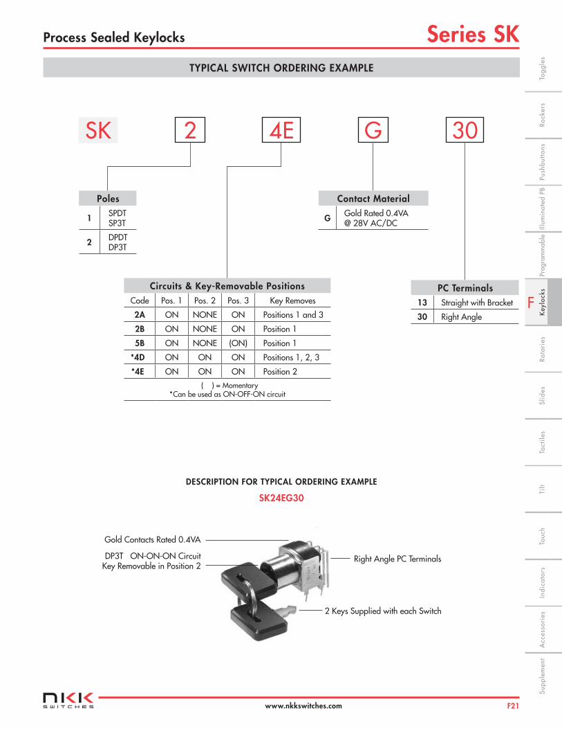
SK24EG30
PC Terminals13 Straight with Bracket
30 Right Angle
Circuits & Key-Removable PositionsCode Pos. 1 Pos. 2 Pos. 3 Key Removes
2A ON NONE ON Positions 1 and 3
2B ON NONE ON Position 1
5B ON NONE (ON) Position 1
*4D ON ON ON Positions 1, 2, 3
*4E ON ON ON Position 2
( ) = Momentary *Can be used as ON-OFF-ON circuit
Contact Material
G Gold Rated 0.4VA @ 28V AC/DC
SK 4E2 G 30
Poles
1 SPDT SP3T
2 DPDT DP3T
Gold Contacts Rated 0.4VA
DP3T ON-ON-ON Circuit Key Removable in Position 2
Right Angle PC Terminals
2 Keys Supplied with each Switch
F
Series SK Process Sealed Keylocks
F22
Indi
cato
rsA
cces
sori
esSu
pple
men
tTa
ctile
sK
eylo
cks
Rota
ries
Push
butto
nsIll
umin
ated
PB
Slid
esPr
ogra
mm
able
Touc
hTi
lt Ro
cker
sTo
ggle
s
www.nkkswitches.com
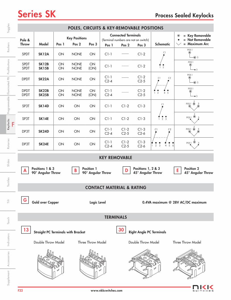
KEY REMOVABLE
Pole & Throw Model
Key Positions
Pos 1 Pos 2 Pos 3
Connected Terminals (Terminal numbers are not on switch)
Pos 1 Pos 2 Pos 3 Schematic
= Key Removable = Not Removable = Maximum Arc
SPDT SK12A ON NONE ON C1-1 ____ C1-2
SPDTSPDT
SK12BSK15B
ONON
NONENONE
ON(ON) C1-1 ____ C1-2
DPDT SK22A ON NONE ON C1-1C2-4
____ C1-2 C2-5
DPDTDPDT
SK22BSK25B
ONON
NONENONE
ON(ON)
C1-1C2-4
____ C1-2C2-5
SP3T SK14D ON ON ON C1-1 C1-2 C1-3
SP3T SK14E ON ON ON C1-1 C1-2 C1-3
DP3T SK24D ON ON ON C1-1C2-4
C1-2C2-5
C1-3C2-6
DP3T SK24E ON ON ON C1-1C2-4
C1-2C2-5
C1-3C2-6
Positions 1 & 3 90° Angular Throw
POLES, CIRCUITS & KEY-REMOVABLE POSITIONS
A
POS 1
3
POS 1
3
•
POS 1
2
3
POS 12
3
Position 1 90° Angular Throw B Positions 1, 2 & 3
45° Angular Throw D Position 2 45° Angular Throw E
TERMINALS
Straight PC Terminals with Bracket 13
Right Angle PC Terminals30
1 2
C1
1 2 4 5
C1 C2
1 2
C1
3
POS 1
3
POS 1
3
POS 12
3
POS 1
2
3
CONTACT MATERIAL & RATING
Gold over Copper Logic Level 0.4VA maximum @ 28V AC/DC maximumG
1 2
C1
3 4 5
C2
6
Double Throw Model Three Throw Model Double Throw Model Three Throw Model
F
Series SKProcess Sealed Keylocks
F23
Indi
cato
rsA
cces
sori
esSu
pple
men
tTa
ctile
sK
eylo
cks
Rota
ries
Push
butto
nsIll
umin
ated
PB
Slid
esPr
ogra
mm
able
Touc
hTi
ltTo
ggle
sRo
cker
s
www.nkkswitches.com
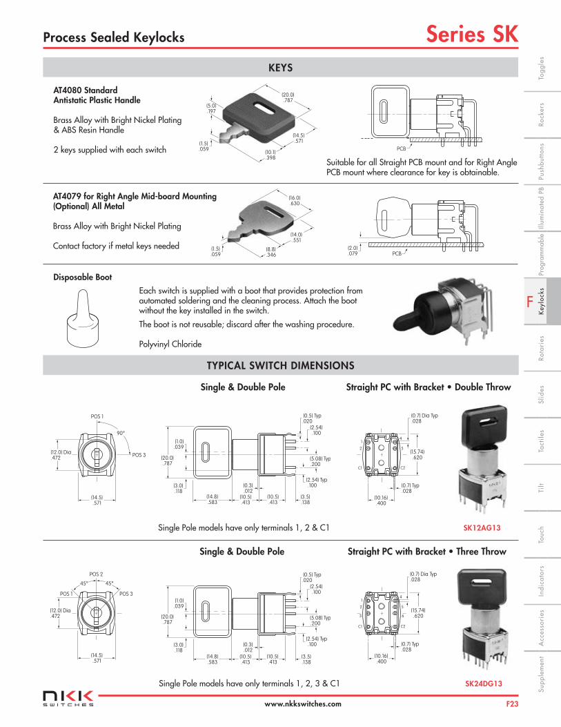
TYPICAL SWITCH DIMENSIONS
Single & Double Pole Straight PC with Bracket • Double Throw
Single & Double Pole Straight PC with Bracket • Three Throw
Single Pole models have only terminals 1, 2 & C1 SK12AG13
Single Pole models have only terminals 1, 2, 3 & C1 SK24DG13
KEYS
Suitable for all Straight PCB mount and for Right Angle PCB mount where clearance for key is obtainable.
AT4080 Standard Antistatic Plastic Handle
Brass Alloy with Bright Nickel Plating& ABS Resin Handle
2 keys supplied with each switch
(5.0).197
(1.5).059
(10.1).398
(14.5).571
(20.0).787
PCB
PCB(2.0).079
(16.0).630
(14.0).551
(8.8).346
(1.5).059
(12.0) Dia.472
90°
POS 1
POS 3
(14.5).571
(20.0).787
(1.0).039
(3.0).118
(14.8).583
(0.3).012
(10.5).413
(10.5).413
(3.5).138
(2.54) Typ.100
(5.08) Typ.200
(2.54).100
(0.5) Typ.020
(15.74).620
1
2
C1 C2
5
4
(0.7) Typ.028
(10.16).400
(0.7) Dia Typ.028
45° 45°
POS 2
POS 1 POS 3
(12.0) Dia.472
(14.5).571
(20.0).787
(1.0).039
(3.0).118
(14.8).583
(0.3).012
(10.5).413
(10.5).413
(3.5).138
(2.54) Typ.100
(5.08) Typ.200
(2.54).100
(0.5) Typ.020
(15.74).620
1
2
C1 C2
5
4
(0.7) Typ.028
(10.16).400
(0.7) Dia Typ.028
3 6
AT4079 for Right Angle Mid-board Mounting (Optional) All Metal
Brass Alloy with Bright Nickel Plating
Contact factory if metal keys needed
Disposable Boot
Each switch is supplied with a boot that provides protection from automated soldering and the cleaning process. Attach the boot without the key installed in the switch.
The boot is not reusable; discard after the washing procedure.
Polyvinyl Chloride

F
Series SK Process Sealed Keylocks
F24
Indi
cato
rsA
cces
sori
esSu
pple
men
tTa
ctile
sK
eylo
cks
Rota
ries
Push
butto
nsIll
umin
ated
PB
Slid
esPr
ogra
mm
able
Touc
hTi
lt Ro
cker
sTo
ggle
s
www.nkkswitches.com
(16.3).642
(9.0).354
(2.54) Typ .100
(2.54).100
(5.08).200
(3.5).138
C11 2 3
TYPICAL SWITCH DIMENSIONS
SK15BG30 Key in Position 3 Double Pole
SK24EG30 Key in Position 1 Double Pole
Straight PC Footprints
Right Angle PC Footprints
(2.54) Typ .100
(0.8) Dia Typ.031
(5.08) .200
(10.16) .400
1
2
C1
3
(2.54) Typ .100
(0.8) Dia Typ.031
(5.08) .200
(10.16) .400
4
5
C2
1
2
C1
36SPDT DPDT SP3T DP3T
SPDT DPDT SP3T DP3T
(7.62) .300
(2.54) .100
(5.08) .200
(0.8) Dia Typ .031
(2.54) .100
(2.54) Typ .100
12
CL
C1
(7.62) .300
(2.54) .100
(5.08) .200
(0.8) Dia Typ .031
(2.54) .100
(2.54) Typ .100
12
CL
C1
C2 45
(7.62) .300
(2.54) .100
(5.08) .200
(0.8) Dia Typ .031
(2.54) .100
(2.54) Typ .100
12
CL
C1
C2 45
3
6
(12.0) Dia .472
90°
(0.5) Typ.020
(15.24).600
POS 1
POS 3
(14.8).583
(5.0).197
(12.4).488
(10.5) .413(0.7) Typ.028
(7.62).300
(0.7) Dia.028
(2.54) .100
(1.0).039
(3.0).118
(20.0).787
(16.3).642
(9.0).354
(2.54) Typ .100
(2.54).100
(5.08).200
(3.5).138
C11 2
(9.0).354
(16.3).642
(2.54) Typ .100
(2.54).100
(5.08).200
(3.5).138
C11 2
(0.7) Dia Typ.028
C254
(12.0) Dia .472
45°
(0.5) Typ.020
(15.24) .600
45°
POS 1
POS 2
POS 3
(3.0).118
(12.4).488
(14.8).583
(5.0).197
(10.5) .413(0.7) Typ.028
(7.62).300
(0.7) Dia.028(2.54) .100
(9.0).354
(16.3).642
(2.54) Typ .100
(2.54).100
(5.08).200
(3.5).138
C11 2
(0.7) Dia Typ.028
C254
3
6
(7.62) .300
(2.54) .100
(5.08) .200
(0.8) Dia Typ .031
(2.54) .100
(2.54) Typ .100
12
CL
C1 3
(2.54) Typ .100
(0.8) Dia Typ.031
(5.08) .200
(10.16) .400
1
2
C1
(15.24) .600
(2.54) Typ .100
(0.8) Dia Typ.031
(5.08) .200
(10.16) .400
4
5
C2
1
2
C1
(15.24) .600
Right Angle Key in Position 1 Single Pole PC Terminals Double Throw
Right Angle Key in Position 2 Single Pole PC Terminals Three Throw
Series SKAntistatic Snap-in Keylock
F25
F
Indi
cato
rsA
cces
sori
esSu
pple
men
tTa
ctile
sK
eylo
cks
Rota
ries
Push
butto
nsIll
umin
ated
PB
Slid
esPr
ogra
mm
able
Touc
hTi
ltTo
ggle
sRo
cker
s
www.nkkswitches.com
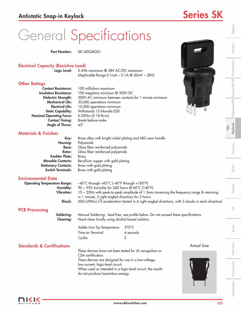
Part Number: SK14DGMG01
Electrical Capacity (Resistive Load) Logic Level: 0.4VA maximum @ 28V AC/DC maximum (Applicable Range 0.1mA ~ 0.1A @ 20mV ~ 28V)
Other Ratings Contact Resistance: 100 milliohms maximum Insulation Resistance: 100 megohms minimum @ 500V DC Dielectric Strength: 500V AC minimum between contacts for 1 minute minimum Mechanical Life: 30,000 operations minimum Electrical Life: 10,000 operations minimum Static Capability: Withstands 15 kilovolts ESD Nominal Operating Force: 0.02Nm (0.18 lb•in) Contact Timing: Break-before-make Angle of Throw: 45°
Materials & Finishes Key: Brass alloy with bright nickel plating and ABS resin handle Housing: Polyamide Base: Glass fiber reinforced polyamide Rotor: Glass fiber reinforced polyamide Tumbler Plate: Brass Movable Contacts: Beryllium copper with gold plating Stationary Contacts: Brass with gold plating Switch Terminals: Brass with gold plating
Environmental Data Operating Temperature Range: –40°C through +85°C (–40°F through +185°F) Humidity: 90 ~ 95% humidity for 240 hours @ 60°C (140°F) Vibration: 10 ~ 55Hz with peak-to-peak amplitude of 1.5mm traversing the frequency range & returning in 1 minute; 3 right angled directions for 2 hours Shock: 50G (490m/s2) acceleration (tested in 6 right angled directions, with 5 shocks in each direction)
PCB Processing Soldering: Manual Soldering: lead-free, see profile below. Do not exceed these specifications. Cleaning: Hand clean locally using alcohol based solution.
Standards & Certifications These devices have not been tested for UL recognition or CSA certification. These devices are designed for use in a low-voltage, low-current, logic-level circuit. When used as intended in a logic-level circuit, the results do not produce hazardous energy.
Solder Iron Tip Temperature 370°CTime on Terminal 4 secondsCycles 2
General Specifications
Actual Size
Series SK Antistatic Snap-in Keylock
F26
F
Indi
cato
rsA
cces
sori
esSu
pple
men
tTa
ctile
sK
eylo
cks
Rota
ries
Push
butto
nsIll
umin
ated
PB
Slid
esPr
ogra
mm
able
Touc
hTi
lt Ro
cker
sTo
ggle
s
www.nkkswitches.com
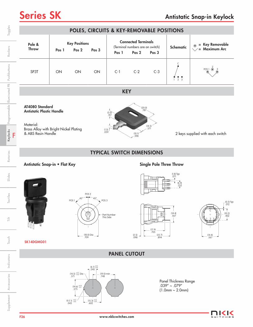
Pole & Throw
Key Positions
Pos 1 Pos 2 Pos 3
Connected Terminals (Terminal numbers are on switch) Pos 1 Pos 2 Pos 3
Schematic = Key Removable = Maximum Arc
SP3T ON ON ON C-1 C-2 C-3
POLES, CIRCUITS & KEY-REMOVABLE POSITIONS
POS 12
3
KEY
TYPICAL SWITCH DIMENSIONS
1 2
C
3
AT4080 Standard Antistatic Plastic Handle
Material: Brass Alloy with Bright Nickel Plating& ABS Resin Handle
(5.0).197
(1.5).059
(10.1).398
(14.5).571
(20.0).787
(14.4).567
C
1 2 3
(10.2).402
(0.3) Typ.012
(14.4).567
(17.9).705
(22.7).894
(2.5).098
PANEL CUTOUT
(19.0) min.748
(6.1).240
+0.2–0.0
(14.5).571
+0.2–0.0
(14.6).575
+0.0–0.1
R (1.1).043
+0.2–0.0 (15.3)
.602
+0.2–0.0
Dia
(6.4).252
(1.8) Typ.071
Part NumberThis Side
POS 1
POS 2
POS 345° 45°
(18.0) Dia.709
Panel Thickness Range.039” ~ .079”(1.0mm ~ 2.0mm)
2 keys supplied with each switch
SK14DGMG01
Antistatic Snap-in • Flat Key Single Pole Three Throw


![NKK - IsM Handbook[1]](https://static.fdocuments.net/doc/165x107/577ce0aa1a28ab9e78b3ce0f/nkk-ism-handbook1.jpg)