Contents Canalis KBA and
53
TDM 04.fm/3 Canalis KBA Schneider Electric Contents Canalis KBA and KBL industrial luminaires 0 Presentation Canalis KBA 88 Description Canalis KBA, 25 and 40 A 92 KBL Industrial luminaires 95 Tap-off units 96 Catalogue numbers / Dimensions Canalis KBA, 25 and 40 A 98 KBL Industrial luminaires 102 Tap-off units 104 Installation Installation scenario 108 Assembly of trunking components 112 << Back
Transcript of Contents Canalis KBA and
TDM 04.fm/3
Can
alis
KB
A
Schneider Electric
Contents Canalis KBA andKBL industrial luminaires 0
PresentationCanalis KBA 88
DescriptionCanalis KBA, 25 and 40 A 92KBL Industrial luminaires 95Tap-off units 96
Catalogue numbers / DimensionsCanalis KBA, 25 and 40 A 98KBL Industrial luminaires 102Tap-off units 104
InstallationInstallation scenario 108Assembly of trunking components 112
<< Back
K02E11000.fm/2 6 avril 2007Schneider Electric
Presentation Canalis KBA 0
For lighting and power socket distribution
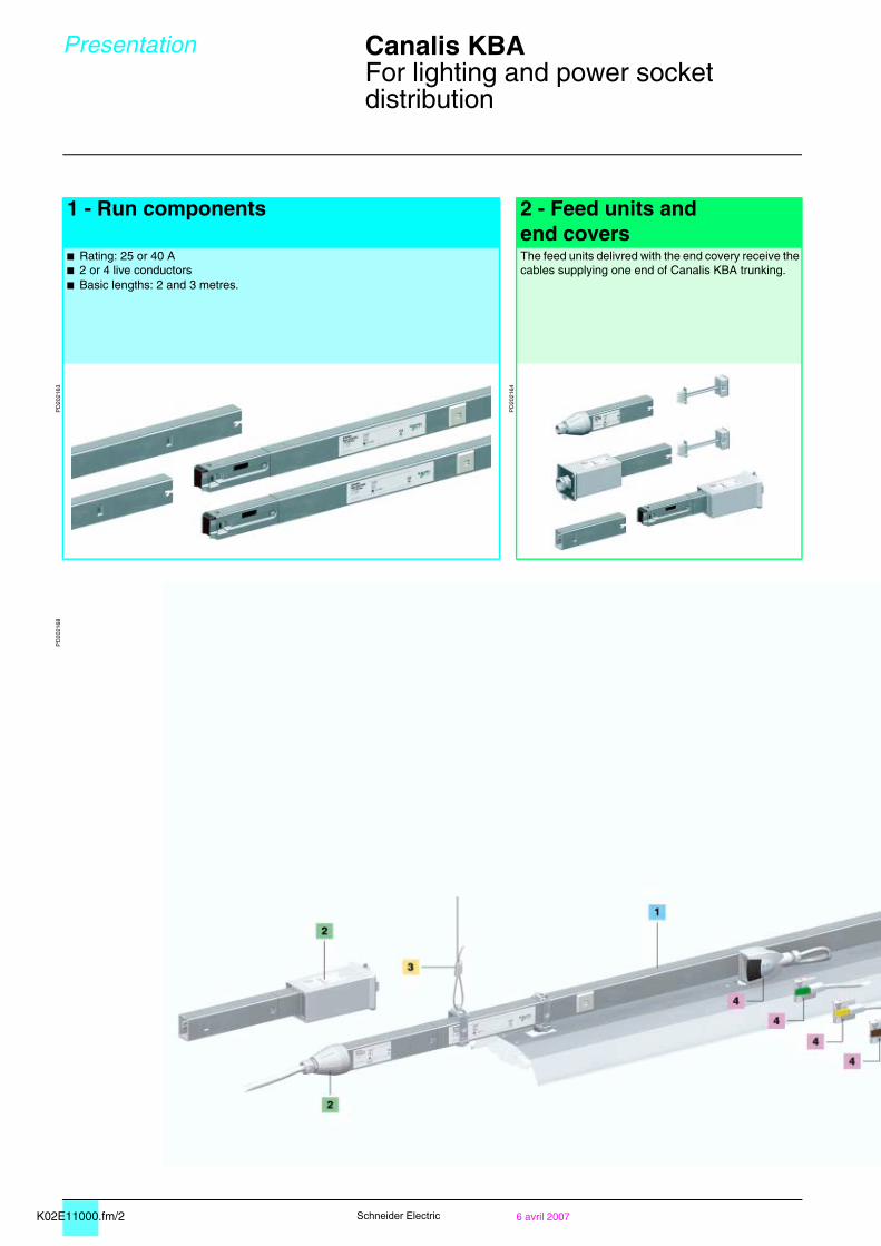
1 - Run components 2 - Feed units and
end coversb Rating: 25 or 40 Ab 2 or 4 live conductorsb Basic lengths: 2 and 3 metres.
The feed units delivred with the end covery receive the cables supplying one end of Canalis KBA trunking.
PD
2021
63
PD
2021
64
PD
2021
68
K02E11000.fm/36 avril 2007
Can
alis
KB
A
Schneider Electric
Presentation Canalis KBA 0
For lighting and power socket distribution
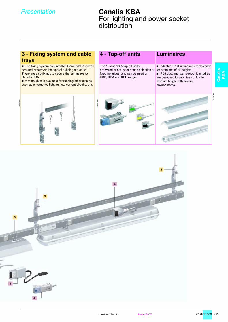
3 - Fixing system and cable trays
4 - Tap-off units Luminaires
b The fixing system ensures that Canalis KBA is well secured, whatever the type of building structure.There are also fixings to secure the luminaires to Canalis KBA.b A metal duct is available for running other circuits such as emergency lighting, low-current circuits, etc.
The 10 and 16 A tap-off units pre-wired or not, offer phase selection or fixed polarities, and can be used on KDP, KDA and KBB ranges.
b Industrial IP20 luminaires are designed for promises of all heightsb IP55 dust and damp-proof luminaires are designed for promises of low to medium height with severe environments.
PD
2021
65
PD
2021
59 PD
2021
67
K02E11000.fm/4 6 avril 2007Schneider Electric
Presentation Canalis KBA 0
For lighting and power socket distribution
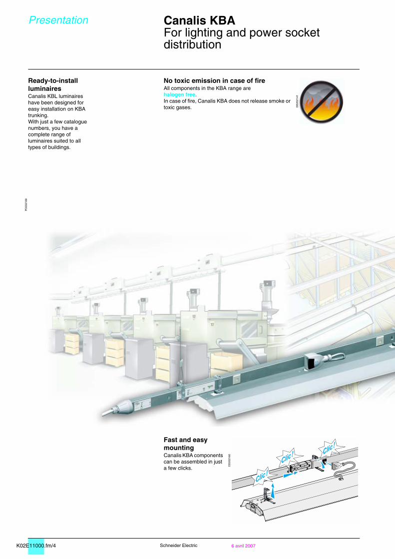
Ready-to-install luminairesCanalis KBL luminaires have been designed for easy installation on KBA trunking.With just a few catalogue numbers, you have a complete range of luminaires suited to all types of buildings.
No toxic emission in case of fireAll components in the KBA range are halogen free.In case of fire, Canalis KBA does not release smoke or toxic gases. D
D20
2141
PD
2021
69
Fast and easy mountingCanalis KBA components can be assembled in just a few clicks.
DD
2021
60
K02E11000.fm/56 avril 2007
Can
alis
KB
A
Schneider Electric
Presentation Canalis KBA 0
For lighting and power socket distribution
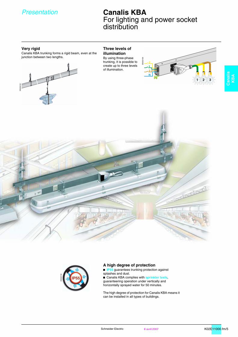
Very rigidCanalis KBA trunking forms a rigid beam, even at the junction between two lengths.
Three levels of illuminationBy using three-phase trunking, it is possible to create up to three levels of illumination.
DD
2021
58
DD
2021
61
A high degree of protectionb IP55 guarantees trunking protection against splashes and dust.b Canalis KBA complies with sprinkler tests, guaranteering operation under vertically and horizontally sprayed water for 50 minutes.
The high degree of protection for Canalis KBA means it can be installed in all types of buildings.
DD
2021
42
K02E12000.fm/2 6 avril 2007Schneider Electric
Description Canalis KBA, 25 and 40 A 0
Busbar trunking for lighting andpower socket distribution
IP55Ue = 230...400 VGalvanised or RAL 9010 white
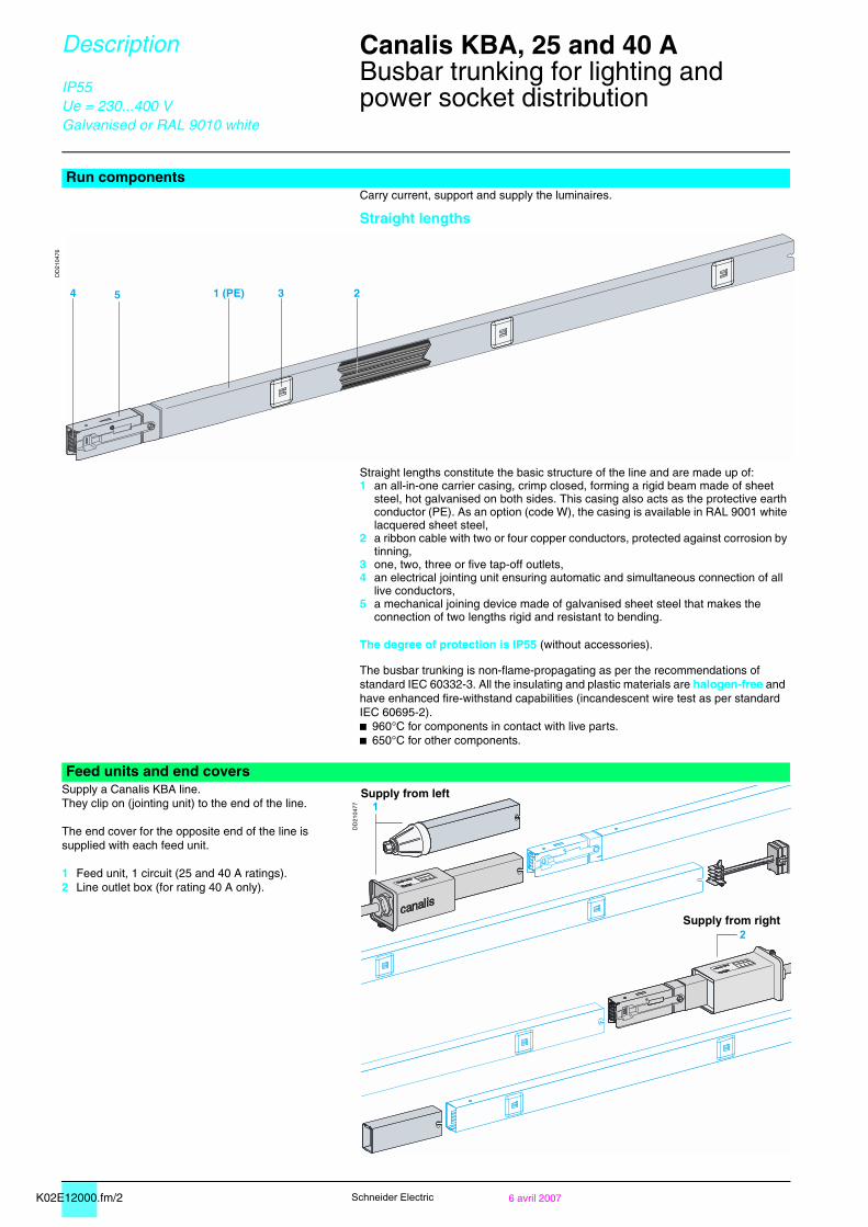
Run componentsCarry current, support and supply the luminaires.
Straight lengths
DD
2104
76
Straight lengths constitute the basic structure of the line and are made up of:1 an all-in-one carrier casing, crimp closed, forming a rigid beam made of sheet
steel, hot galvanised on both sides. This casing also acts as the protective earth conductor (PE). As an option (code W), the casing is available in RAL 9001 white lacquered sheet steel,
2 a ribbon cable with two or four copper conductors, protected against corrosion by tinning,
3 one, two, three or five tap-off outlets,4 an electrical jointing unit ensuring automatic and simultaneous connection of all
live conductors,5 a mechanical joining device made of galvanised sheet steel that makes the
connection of two lengths rigid and resistant to bending.
The degree of protection is IP55 (without accessories).
The busbar trunking is non-flame-propagating as per the recommendations of standard IEC 60332-3. All the insulating and plastic materials are halogen-free and have enhanced fire-withstand capabilities (incandescent wire test as per standard IEC 60695-2).b 960°C for components in contact with live parts.b 650°C for other components.
Feed units and end coversSupply a Canalis KBA line.They clip on (jointing unit) to the end of the line.
The end cover for the opposite end of the line is supplied with each feed unit.
1 Feed unit, 1 circuit (25 and 40 A ratings).2 Line outlet box (for rating 40 A only).
DD
2104
77
54 1 (PE) 3 2
1
2
Supply from left
Supply from right
K02E12000.fm/36 avril 2007
Can
alis
KB
A
Schneider Electric
Description Canalis KBA, 25 and 40 A 0
Busbar trunking for lighting andpower socket distribution
IP55Ue = 230...400 VGalvanised or RAL 9010 white
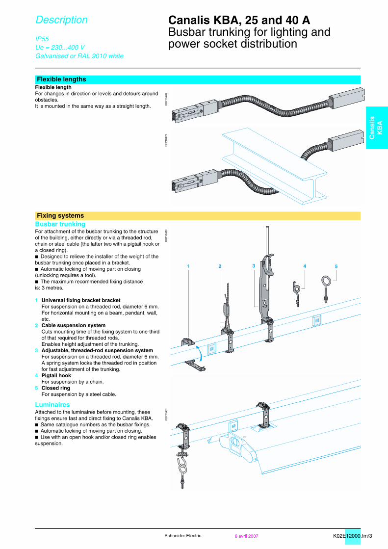
Flexible lengthsFlexible lengthFor changes in direction or levels and detours around obstacles.It is mounted in the same way as a straight length. D
D21
0478
DD
2104
79
Fixing systemsBusbar trunkingFor attachment of the busbar trunking to the structure of the building, either directly or via a threaded rod, chain or steel cable (the latter two with a pigtail hook or a closed ring).b Designed to relieve the installer of the weight of the busbar trunking once placed in a bracket.b Automatic locking of moving part on closing (unlocking requires a tool).b The maximum recommended fixing distance is: 3 metres.
1 Universal fixing bracket bracketFor suspension on a threaded rod, diameter 6 mm.For horizontal mounting on a beam, pendant, wall, etc.
2 Cable suspension systemCuts mounting time of the fixing system to one-third of that required for threaded rods.Enables height adjustment of the trunking.
3 Adjustable, threaded-rod suspension systemFor suspension on a threaded rod, diameter 6 mm. A spring system locks the threaded rod in position for fast adjustment of the trunking.
4 Pigtail hookFor suspension by a chain.
5 Closed ringFor suspension by a steel cable.
LuminairesAttached to the luminaires before mounting, these fixings ensure fast and direct fixing to Canalis KBA.b Same catalogue numbers as the busbar fixings.b Automatic locking of moving part on closing.b Use with an open hook and/or closed ring enables suspension.
DD
2104
80D
D21
0481
4 52 31
K02E12000.fm/4 6 avril 2007Schneider Electric
Description Canalis KBA, 25 and 40 A 0
Busbar trunking for lighting andpower socket distribution
IP55Ue = 230...400 VGalvanised or RAL 9010 white
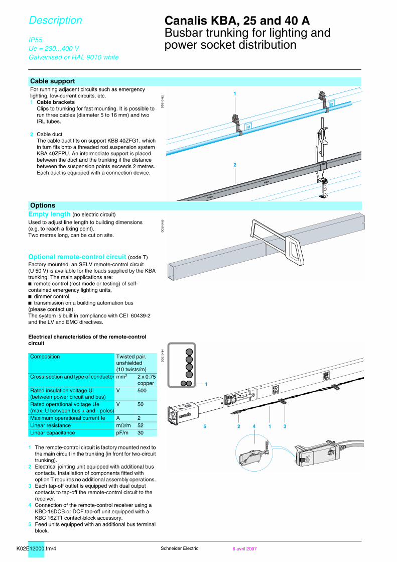
Cable supportFor running adjacent circuits such as emergency lighting, low-current circuits, etc.1 Cable brackets
Clips to trunking for fast mounting. It is possible to run three cables (diameter 5 to 16 mm) and two IRL tubes.
2 Cable ductThe cable duct fits on support KBB 40ZFG1, which in turn fits onto a threaded rod suspension system KBA 40ZFPU. An intermediate support is placed between the duct and the trunking if the distance between the suspension points exceeds 2 metres.Each duct is equipped with a connection device.
DD
2104
82
OptionsEmpty length (no electric circuit)
DD
2104
83Used to adjust line length to building dimensions (e.g. to reach a fixing point).Two metres long, can be cut on site.
Optional remote-control circuit (code T)Factory mounted, an SELV remote-control circuit (U 50 V) is available for the loads supplied by the KBA trunking. The main applications are: b remote control (rest mode or testing) of self-contained emergency lighting units,b dimmer control,b transmission on a building automation bus (please contact us).The system is built in compliance with CEI 60439-2 and the LV and EMC directives.
Electrical characteristics of the remote-control circuit
DD
2104
84
Composition Twisted pair,unshielded(10 twists/m)
Cross-section and type of conductor mm2 2 x 0.75 copper
Rated insulation voltage Ui(between power circuit and bus)
V 500
Rated operational voltage Ue(max. U between bus + and - poles)
V 50
Maximum operational current Ie A 2Linear resistance mΩ/m 52Linear capacitance pF/m 30
1 The remote-control circuit is factory mounted next to the main circuit in the trunking (in front for two-circuit trunking).
2 Electrical jointing unit equipped with additional bus contacts. Installation of components fitted with option T requires no additional assembly operations.
3 Each tap-off outlet is equipped with dual output contacts to tap-off the remote-control circuit to the receiver.
4 Connection of the remote-control receiver using a KBC-16DCB or DCF tap-off unit equipped with a KBC 16ZT1 contact-block accessory.
5 Feed units equipped with an additional bus terminal block.
1
2
1
25 1 34
K02E12000.fm/56 avril 2007
Can
alis
KB
A
Schneider Electric
Description KBL Industrial luminaires 0
For Canalis KBA
Ue = 230...400 VRAL 9010 white
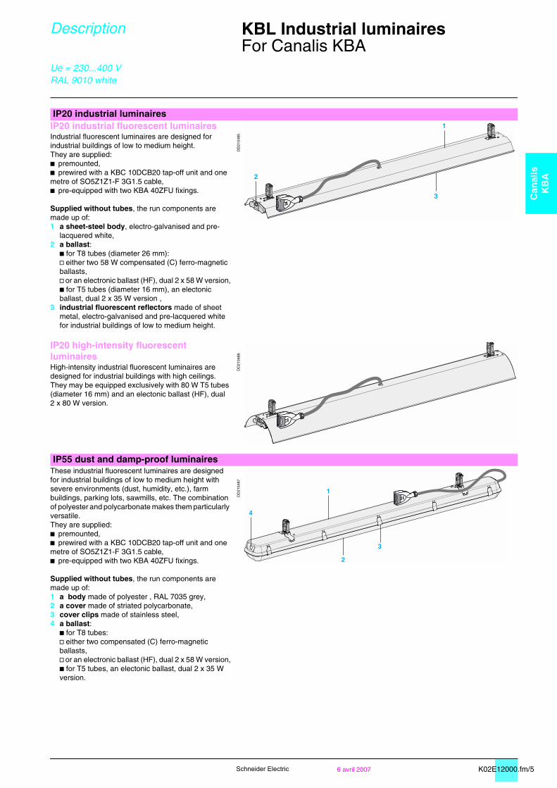
IP20 industrial luminairesIP20 industrial fluorescent luminairesIndustrial fluorescent luminaires are designed for industrial buildings of low to medium height.They are supplied:b premounted,b prewired with a KBC 10DCB20 tap-off unit and one metre of SO5Z1Z1-F 3G1.5 cable,b pre-equipped with two KBA 40ZFU fixings.
Supplied without tubes, the run components are made up of:1 a sheet-steel body, electro-galvanised and pre-
lacquered white,2 a ballast:
b for T8 tubes (diameter 26 mm):v either two 58 W compensated (C) ferro-magnetic ballasts,v or an electronic ballast (HF), dual 2 x 58 W version,b for T5 tubes (diameter 16 mm), an electonic ballast, dual 2 x 35 W version ,
3 industrial fluorescent reflectors made of sheet metal, electro-galvanised and pre-lacquered white for industrial buildings of low to medium height.
DD
2104
85
IP20 high-intensity fluorescent luminairesHigh-intensity industrial fluorescent luminaires are designed for industrial buildings with high ceilings. They may be equipped exclusively with 80 W T5 tubes (diameter 16 mm) and an electonic ballast (HF), dual 2 x 80 W version.
DD
2104
86
IP55 dust and damp-proof luminairesThese industrial fluorescent luminaires are designed for industrial buildings of low to medium height with severe environments (dust, humidity, etc.), farm buildings, parking lots, sawmills, etc. The combination of polyester and polycarbonate makes them particularly versatile.They are supplied:b premounted,b prewired with a KBC 10DCB20 tap-off unit and one metre of SO5Z1Z1-F 3G1.5 cable,b pre-equipped with two KBA 40ZFU fixings.
Supplied without tubes, the run components are made up of:1 a body made of polyester , RAL 7035 grey,2 a cover made of striated polycarbonate,3 cover clips made of stainless steel,4 a ballast:
b for T8 tubes:v either two compensated (C) ferro-magnetic ballasts,v or an electronic ballast (HF), dual 2 x 58 W version,b for T5 tubes, an electonic ballast, dual 2 x 35 W version.
DD
2104
87

K04E12010.fm/2 6 avril 2007Schneider Electric
Description Canalis KDP, KBA and KBB 0
Busbar trunking for lighting andpower socket distributionTap-off units
IP55Ue = 230...400 V
DD
2100
68
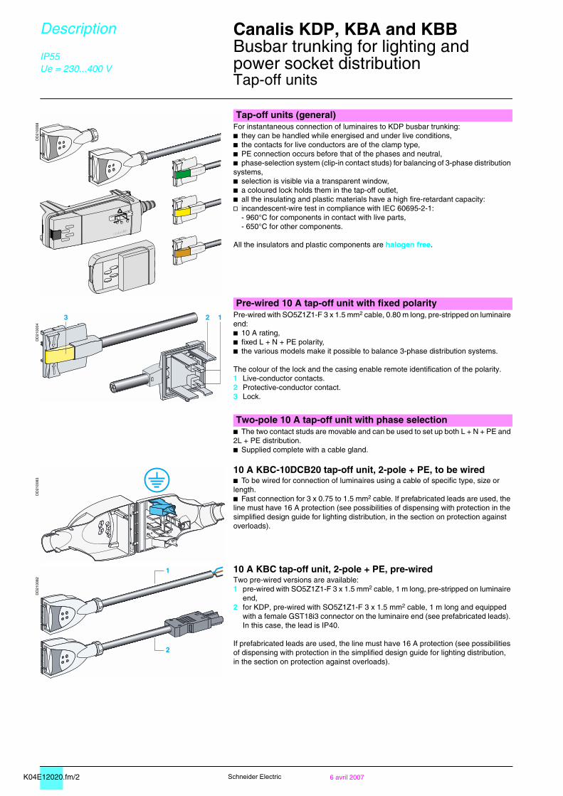
Tap-off units (general)For instantaneous connection of luminaires to KDP busbar trunking:b they can be handled while energised and under live conditions,b the contacts for live conductors are of the clamp type,b PE connection occurs before that of the phases and neutral,b phase-selection system (clip-in contact studs) for balancing of 3-phase distribution systems,b selection is visible via a transparent window,b a coloured lock holds them in the tap-off outlet,b all the insulating and plastic materials have a high fire-retardant capacity:v incandescent-wire test in compliance with IEC 60695-2 :
- 960°C for components in contact with live parts,- 650°C for other components.
All the insulators and plastic components are halogen free.
Pre-wired 10 A tap-off unit with fixed polarity
DD
2100
04
Pre-wired with SO5Z1Z1-F 3 x 1.5 mm2 cable, 0.80 m long, pre-stripped on luminaire end:b 10 A rating,b fixed L + N + PE polarity,b the various models make it possible to balance 3-phase distribution systems.
The colour of the lock and the casing enable remote identification of the polarity.1 Live-conductor contacts.2 Protective-conductor contact.3 Lock.
Two-pole 10 A tap-off unit with phase selectionb The two contact studs are movable and can be used to set up both L + N + PE and 2L + PE distribution.b Supplied complete with a cable gland.
DD
2100
83
10 A KBC-10DCB20 tap-off unit, 2-pole + PE, to be wiredb To be wired for connection of luminaires using a cable of specific type, size or length.b Fast connection for 3 x 0.75 to 1.5 mm2 cable. If prefabricated leads are used, the line must have 16 A protection (see possibilities of dispensing with protection in the simplified design guide for lighting distribution, in the section on protection against overloads).
DD
2100
82
10 A KBC tap-off unit, 2-pole + PE, pre-wiredTwo pre-wired versions are available:1 pre-wired with SO5Z1Z1-F 3 x 1.5 mm2 cable, 1 m long, pre-stripped on luminaire
end,2 for KDP, pre-wired with SO5Z1Z1-F 3 x 1.5 mm2 cable, 1 m long and equipped
with a female GST18i3 connector on the luminaire end (see prefabricated leads). In this case, the lead is IP40.
If prefabricated leads are used, the line must have 16 A protection (see possibilities of dispensing with protection in the simplified design guide for lighting distribution, in the section on protection against overloads).
123
!
1
2

K04E12010.fm/36 avril 2007
Can
alis
KB
A
Schneider Electric
Description Canalis KDP, KBA and KBB 0
Busbar trunking for lighting andpower socket distributionTap-off units
IP55Ue = 230...400 V
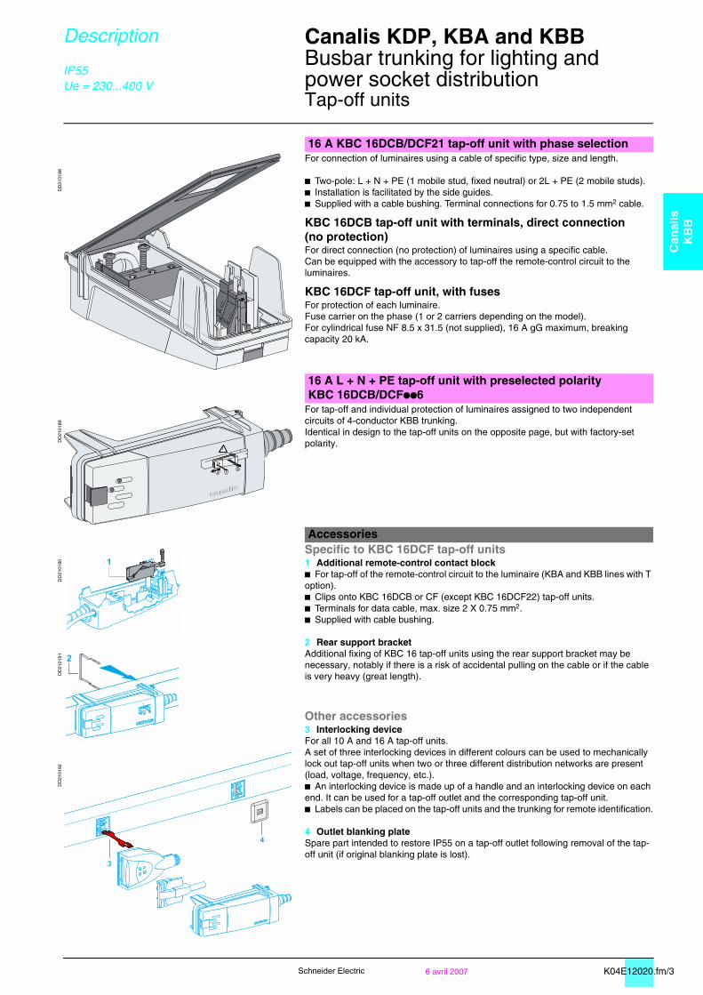
16 A KBC 16DCB/DCF21 tap-off unit with phase selection
DD
2101
88
For connection of luminaires using a cable of specific type, size and length.
b Two-pole: L + N + PE (1 mobile stud, fixed neutral) or 2L + PE (2 mobile studs). b Installation is facilitated by the side guides. b Supplied with a cable bushing. Terminal connections for 0.75 to 1.5 mm2 cable.
KBC 16DCB tap-off unit with terminals, direct connection (no protection)For direct connection (no protection) of luminaires using a specific cable.Can be equipped with the accessory to tap-off the remote-control circuit to the luminaires.
KBC 16DCF tap-off unit, with fusesFor protection of each luminaire.Fuse carrier on the phase (1 or 2 carriers depending on the model).For cylindrical fuse NF 8.5 x 31.5 (not supplied), 16 A gG maximum, breaking capacity 20 kA.
16 A L + N + PE tap-off unit with preselected polarityKBC 16DCB/DCFpp6
DD
2101
89
For tap-off and individual protection of luminaires assigned to two independent circuits of 4-conductor KBA trunking.Identical in design to the tap-off units on the opposite page, but with factory-set polarity.
Accessories
DD
2101
90
Specific to KBC 16DCF tap-off units1 Additional remote-control contact blockb For tap-off of the remote-control circuit to the luminaire (KBA and KBB lines with T option).b Clips onto KBC 16DCB or CF (except KBC 16DCF22) tap-off units.b Terminals for data cable, max. size 2 X 0.75 mm2. b Supplied with cable bushing.
2 Rear support bracketAdditional fixing of KBC 16 tap-off units using the rear support bracket may be necessary, notably if there is a risk of accidental pulling on the cable or if the cable is very heavy (great length).
Other accessories3 Interlocking device For all 10 A and 16 A tap-off units.A set of three interlocking devices in different colours can be used to mechanically lock out tap-off units when two or three different distribution networks are present (load, voltage, frequency, etc.).b An interlocking device is made up of a handle and an interlocking device on each end. It can be used for a tap-off outlet and the corresponding tap-off unit.b Labels can be placed on the tap-off units and the trunking for remote identification.
4 Outlet blanking plateSpare part intended to restore IP55 on a tap-off outlet following removal of the tap-off unit (if original blanking plate is lost).
DD
2101
91D
D21
0192
123
!
1
2
123
!
3
4
K02E21000.fm/2 6 avril 2007Schneider Electric
Catalogue numbers Dimensions
Canalis KBA, 25 and 40 A 0
Busbar trunking for lighting andpower socket distributionOptional remote-control circuit (code T)Optional white-lacquered metal enclosure (code W)
IP55Ue = 230...400 VGalvanised or RAL 9010 white
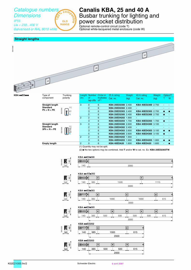
Straight lengths
DD
2100
86
KBA ppEDppp Type of component
Trunking polarity
Length(m)
Numberoftap-offs
Order in multiples of(1)
25 A rating Weight 40 A rating Weight Option(2)
Cat. no. (kg) Cat. no. (kg) T W
Straight lengthStandardPh + N + PE
DD
2100
95
3 0 6 KBA 25ED2300 2.400 KBA 40ED2300 2.700 - -2 6 KBA 25ED2302 2.400 - - - -3 6 KBA 25ED2303 2.400 KBA 40ED2303 2.700 b b5 6 KBA 25ED2305 2.400 KBA 40ED2305 2.700 b -
2 2 6 KBA 25ED4202 1.900 - - - -3 6 KBA 40ED2203 1.700 KBA 40ED2203 1.700 b -
Straight lengthStandard3Ph + N + PE
DD
2100
96
3 0 6 KBA 25ED4300 2.600 KBA 40ED4300 3.100 - -2 6 KBA 25ED4302 2.400 - - - -3 6 KBA 25ED4303 2.600 KBA 40ED4303 3.100 b b5 6 KBA 25ED4305 2.600 KBA 40ED4305 3.100 b -
2 2 6 KBA 25ED4202 1.900 - - - -3 6 KBA 40ED4203 1.900 KBA 40ED4203 1.900 b b
Empty length 2 0 6 KBA 40EDA20 1.600 KBA 40EDA20 1.600 - b(1) Quantity may not be split.(2) b the two options may be combined. Add T and/or W to cat. no. Ex: KBA 25ED2303TW.
DD
2100
26D
D21
0025
N
L1
PE
N
L1L2
L3
PE
KBA ED203
KBA ED202
140 385 1000 615
2000
30
46
30
46
140 385 500500 615
2000
K02E21000.fm/36 avril 2007
Can
alis
KB
A
Schneider Electric
Catalogue numbers Dimensions
Canalis KBA, 25 and 40 A 0
Busbar trunking for lighting andpower socket distributionOptional remote-control circuit (code T)Optional white-lacquered metal enclosure (code W)
IP55Ue = 230...400 VGalvanised or RAL 9010 white
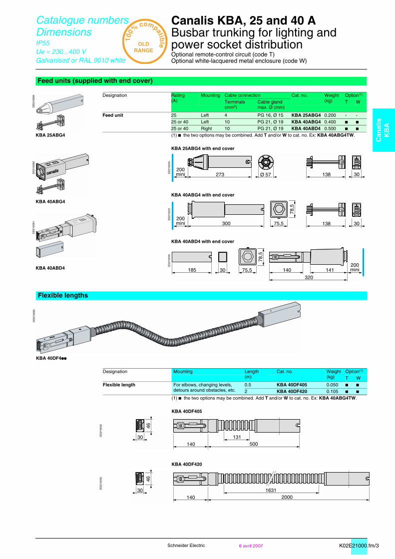
Feed units (supplied with end cover)
DD
2100
94 Designation Rating(A)
Mounting Cable connection Cat. no. Weight(kg)
Option(1)
Terminals(mm2)
Cable glandmax. Ø (mm)
T W
Feed unit 25 Left 4 PG 16, Ø 15 KBA 25ABG4 0.200 - -25 or 40 Left 10 PG 21, Ø 19 KBA 40ABG4 0.400 b b25 or 40 Right 10 PG 21, Ø 19 KBA 40ABD4 0.500 b b
KBA 25ABG4 (1) b the two options may be combined. Add T and/or W to cat. no. Ex: KBA 40ABG4TW.
KBA 25ABG4 with end cover
DD
2100
92
DD
2100
34
KBA 40ABG4 with end coverKBA 40ABG4
DD
2100
31
DD
2100
91
KBA 40ABD4 with end cover
DD
2100
30
KBA 40ABD4
Flexible lengths
DD
2100
93
KBA 40DF4pp
Designation Mounting Length(m)
Cat. no. Weight(kg)
Option(1)
T WFlexible length For elbows, changing levels,
detours around obstacles, etc.0.5 KBA 40DF405 0.050 b b2 KBA 40DF420 0.105 b b
(1) b the two options may be combined. Add T and/or W to cat. no. Ex: KBA 40ABG4TW.
KBA 40DF405
DD
2100
32
KBA 40DF420
DD
2100
33
Ø 57 273200mini 30138
300 75,5200mini 30
78,5
138
78,5
185200mini14114075,530
320
30
46
500140131
30
46
20001401631
K02E21000.fm/4 6 avril 2007Schneider Electric
Catalogue numbers Dimensions
Canalis KBA, 25 and 40 A 0
Busbar trunking for lighting andpower socket distributionOptional white-lacquered metal enclosure (code W)
IP55Ue = 230...400 VGalvanised or RAL 9010 white
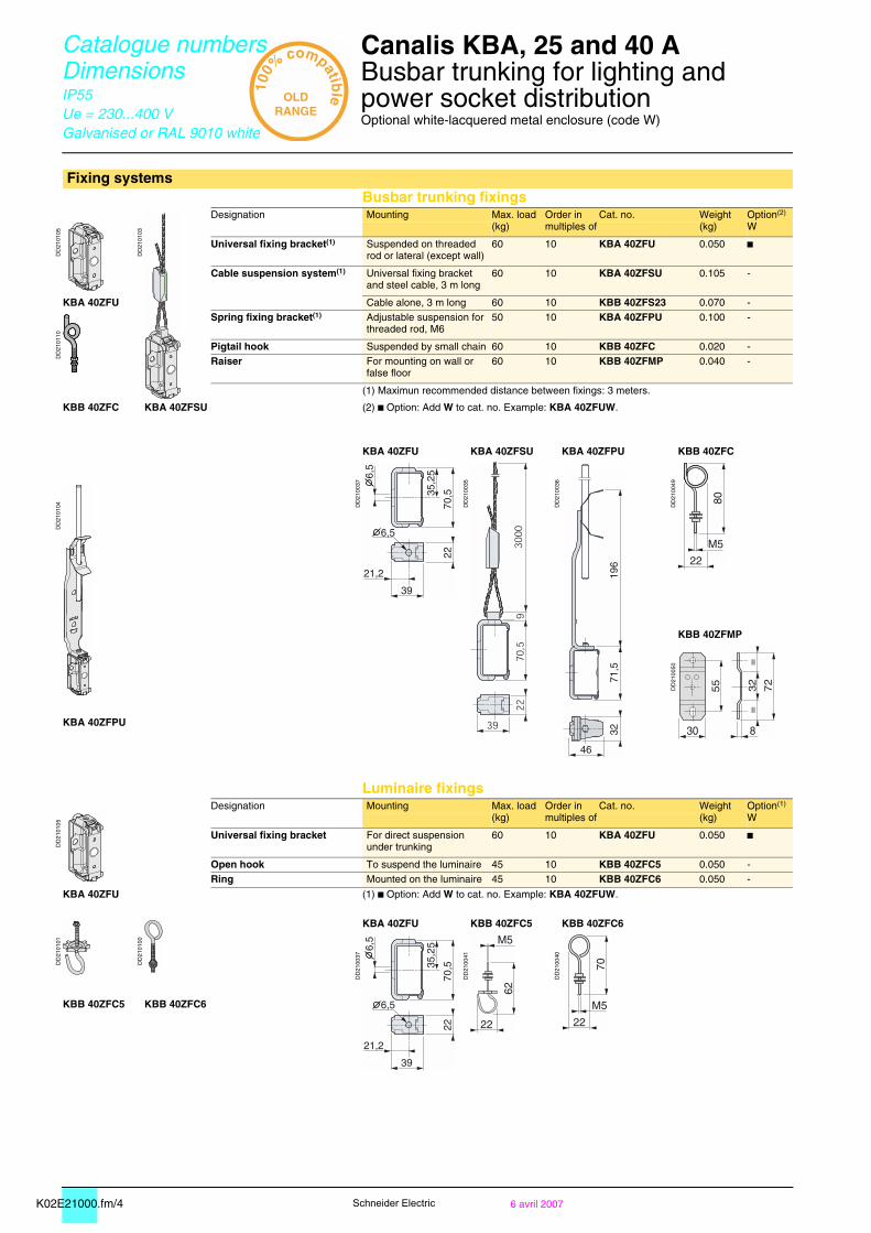
Fixing systemsBusbar trunking fixings
DD
2101
05
DD
2101
03
Designation Mounting Max. load(kg)
Order in multiples of
Cat. no. Weight(kg)
Option(2)
W
Universal fixing bracket(1) Suspended on threaded rod or lateral (except wall)
60 10 KBA 40ZFU 0.050 b
Cable suspension system(1) Universal fixing bracketand steel cable, 3 m long
60 10 KBA 40ZFSU 0.105 -
KBA 40ZFU Cable alone, 3 m long 60 10 KBB 40ZFS23 0.070 -
DD
2101
10
Spring fixing bracket(1) Adjustable suspension for threaded rod, M6
50 10 KBA 40ZFPU 0.100 -
Pigtail hook Suspended by small chain 60 10 KBB 40ZFC 0.020 -Raiser For mounting on wall or
false floor60 10 KBB 40ZFMP 0.040 -
(1) Maximun recommended distance between fixings: 3 meters.
KBB 40ZFC KBA 40ZFSU (2) b Option: Add W to cat. no. Example: KBA 40ZFUW.
KBA 40ZFU KBA 40ZFSU KBA 40ZFPU KBB 40ZFC
DD
2100
37
DD
2100
35
DD
2100
36
DD
2100
49
DD
2101
04
KBB 40ZFMP
DD
2100
50
KBA 40ZFPU
Luminaire fixings
DD
2101
05
Designation Mounting Max. load(kg)
Order in multiples of
Cat. no. Weight(kg)
Option(1)
W
Universal fixing bracket For direct suspension under trunking
60 10 KBA 40ZFU 0.050 b
Open hook To suspend the luminaire 45 10 KBB 40ZFC5 0.050 -Ring Mounted on the luminaire 45 10 KBB 40ZFC6 0.050 -
KBA 40ZFU (1) b Option: Add W to cat. no. Example: KBA 40ZFUW.
DD
2101
01
DD
2101
00
KBA 40ZFU KBB 40ZFC5 KBB 40ZFC6
DD
2100
37
DD
2100
41
DD
2100
40
KBB 40ZFC5 KBB 40ZFC6
K02E21000.fm/56 avril 2007
Can
alis
KB
A
Schneider Electric
Catalogue numbers Dimensions
Canalis KBA, 25 and 40 A 0
Busbar trunking for lighting andpower socket distribution
IP55Ue = 230...400 VGalvanised or RAL 9010 white
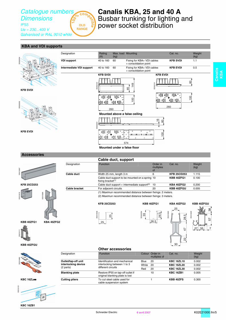
KBA and VDI supports
DD
2022
04
Designation Rating(A)
Max. load (kg)
Mounting Cat. no. Weight(kg)
VDI support 40 to 160 60 Fixing for KBA+ VDI cables+ consolidation point
KFB SVDI 1.1
Intermediate VDI support 40 to 160 60 Fixing for KBA+ VDI cables+ consolidation point
KFB EVDI 0.5
KFB SVDI KFB EVDI
DD
2021
50
DD
2021
51
KFB SVDI
DD
2022
05
Mounted above a false ceiling
DD
2022
01
KFB EVDI
Mounted under a false floor
AccessoriesCable duct, support
DD
2100
97
Designation Function Order in multiples of
Cat. no. Weight(kg)
Cable duct Width 25 mm, length 3 m 6 KFB 25CD253 1.115Cable duct support to be mounted on a spring fixing bracket(1)
10 KBB 40ZFG1 0.100
KFB 25CD253 Cable duct support + intermediate support(2) 10 KBA 40ZFG2 0.200
DD
2103
15
DD
2105
89
Cable bracket For adjacent circuits 20 KBB 40ZFGU 0.005(1) Maximun recommended distance between fixings: 2 meters.(2) Maximun recommended distance between fixings: 3 meters.
KFB 25CD253 KBB 40ZFG1 KBA 40ZFG2 KBB 40ZFGU
DD
2100
38
DD
2022
94
DD
2105
90
DD
2100
29
KBB 40ZFG1 KBA 40ZFG2
DD
2101
11
KBB 40ZFGU
Other accessories
DD
2100
85
Designation Function Colour Order in multiples of
Cat. no. Weight(kg)
Outlet/tap-off unit interlocking device(2 parts)
Identification and mechanical interlocking between 1 to 3 different circuits
Blue 20 KBC 16ZL10 0.002White 20 KBC 16ZL20 0.002Red 20 KBC 16ZL30 0.002
Blanking plate Restore IP55 on tap-off outlet if original blanking plate is lost
10 KBC 16ZB1 0.005
KBC 16ZLpp Cutting pliers To cut steel cable used for cable suspension system
1 KBB 40ZFS 0.300
DD
2101
31
KBC 16ZB1
33 727
3857
25
25
25
30
28,5
4722
K02E22000.fm/2 6 avril 2007Schneider Electric
Catalogue numbers Dimensions
KBL Industrial luminaires 0
For Canalis KBA
Ue = 230...400 VRAL 9010 white
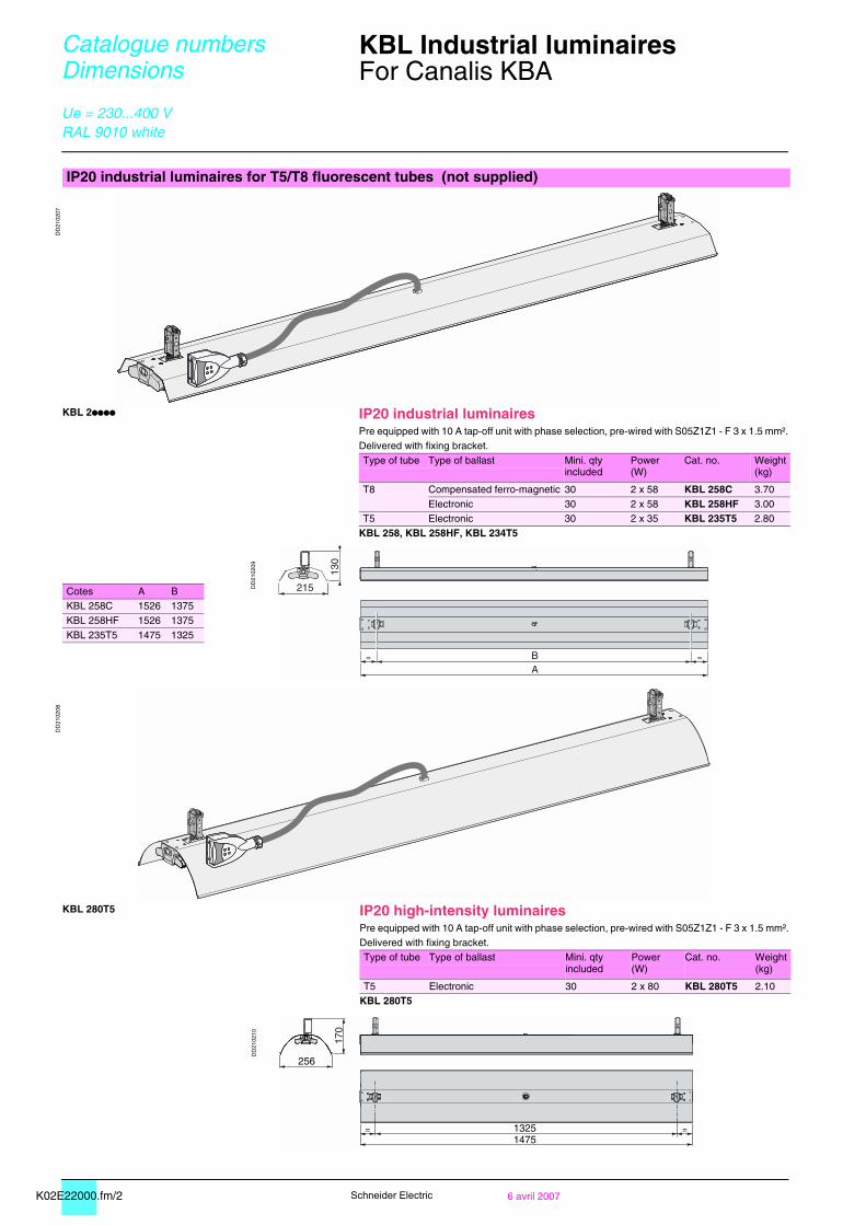
IP20 industrial luminaires for T5/T8 fluorescent tubes (not supplied)
DD
2102
07
KBL 2pppp IP20 industrial luminairesPre equipped with 10 A tap-off unit with phase selection, pre-wired with S05Z1Z1 - F 3 x 1.5 mm².Delivered with fixing bracket.Type of tube Type of ballast Mini. qty
includedPower(W)
Cat. no. Weight(kg)
T8 Compensated ferro-magnetic 30 2 x 58 KBL 258C 3.70Electronic 30 2 x 58 KBL 258HF 3.00
T5 Electronic 30 2 x 35 KBL 235T5 2.80KBL 258, KBL 258HF, KBL 234T5
DD
2102
09
Cotes A BKBL 258C 1526 1375KBL 258HF 1526 1375KBL 235T5 1475 1325
DD
2102
08
KBL 280T5 IP20 high-intensity luminairesPre equipped with 10 A tap-off unit with phase selection, pre-wired with S05Z1Z1 - F 3 x 1.5 mm².Delivered with fixing bracket.Type of tube Type of ballast Mini. qty
includedPower(W)
Cat. no. Weight(kg)
T5 Electronic 30 2 x 80 KBL 280T5 2.10KBL 280T5
DD
2102
10
K02E22000.fm/36 avril 2007
Can
alis
KB
L
Schneider Electric
Catalogue numbers Dimensions
KBL Industrial luminaires 0
For Canalis KBA
Ue = 230...400 VRAL 9010 white
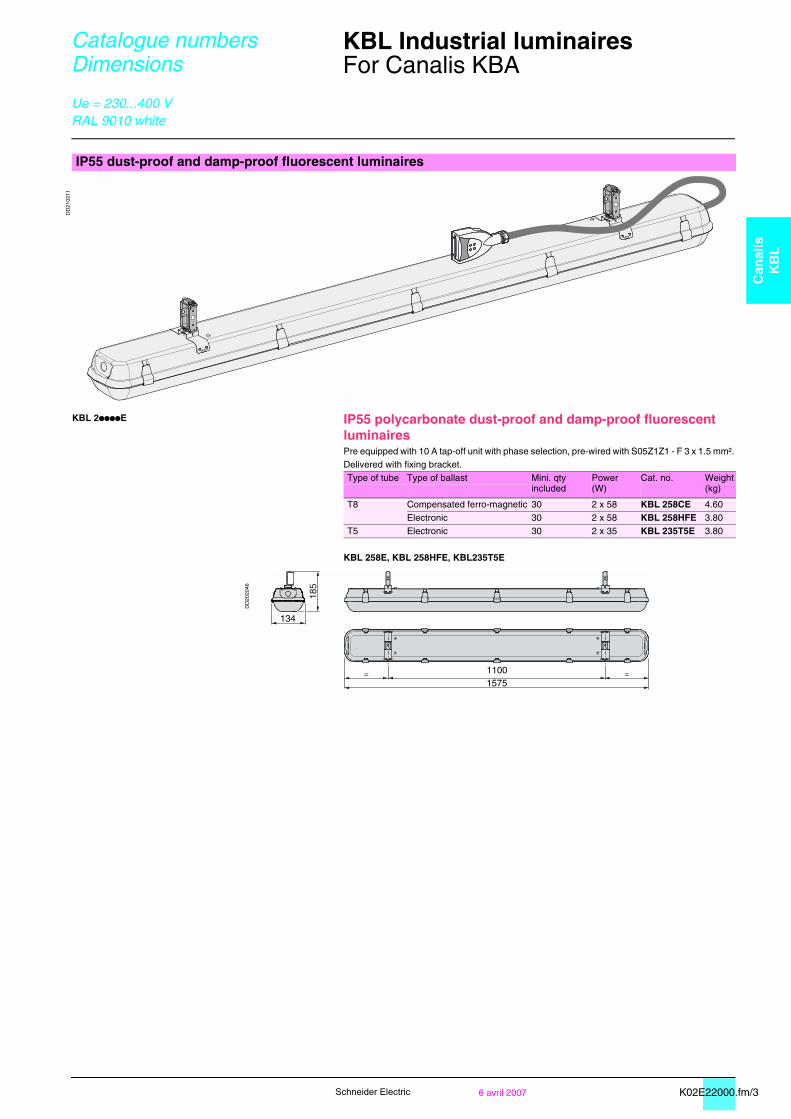
IP55 dust-proof and damp-proof fluorescent luminaires
DD
2102
11
KBL 2ppppE IP55 polycarbonate dust-proof and damp-proof fluorescent luminairesPre equipped with 10 A tap-off unit with phase selection, pre-wired with S05Z1Z1 - F 3 x 1.5 mm².Delivered with fixing bracket.Type of tube Type of ballast Mini. qty
includedPower(W)
Cat. no. Weight(kg)
T8 Compensated ferro-magnetic 30 2 x 58 KBL 258CE 4.60Electronic 30 2 x 58 KBL 258HFE 3.80
T5 Electronic 30 2 x 35 KBL 235T5E 3.80
KBL 258E, KBL 258HFE, KBL235T5E
DD
2020
46

K04E22020.fm/2 6 avril 2007Schneider Electric
Catalogue numbers Dimensions
Canalis KDP, KBA and KBB tap-off units 0
For lighting and power socket distribution
IP55Ue = 230...400 V
10 A tap-off unit, direct connection10 A tap-off unit, L + N + PE, with fixed polarity,pre-wired SO5Z1Z1-F 3 x 1.5 mm2, 0.8 m long
DD
2101
15
Type of busbar trunking Polarity Colourof lock
Order inmultiples of
Cat. no. Weight(kg)
L1 + N Green 10 KBC 10DCS101 0.100
DD
2101
26
DD
2101
21
KBC 10DCS101 L2 + N Yellow 10 KBC 10DCS201 0.100
DD
2101
13
Single-circuit switching
Balancing on 3 phases or 3-circuit switching
L3 + N Brown 10 KBC 10DCS301 0.100
KBC 10DCS201 KBC 10CSp01
DD
2101
14
DD
2100
51
KBC 10DCS301
10 A tap-off unit, L + L + PE or L + N + PE, with phase selectionType of busbar trunking Polarity Order in
multiples ofCat. no. Weight
(kg)
L1 + N or L2 + N or L3 + NL1 + L2 or L1 + L3 or L2 + L3L2 + N2 or L3 + N3
10 KBC 10DCB20 0.065
DD
2101
12
DD
2101
26
DD
2101
21
DD
2101
28
KBC 10DCB20 All types possible
10 A tap-off unit, L + L + PE or L + N + PE, with phase selection,pre-wired SO5Z1Z1-F 3 x 1.5 mm2, 1 m long
Type of busbar trunking Polarity Pre-equipped withfemale GST18i3connector
Order inmultiplesof
Cat. no. Weight(kg)
L1 + N or L2 + N or L3 + NL1 + L2 or L1 + L3 or L2 + L3L2 + N2 or L3 + N3
No 10 KBC 10DCC211 0.165
DD
2101
16
DD
2101
26
DD
2101
21
DD
2101
28
Yes(1) 10 KBC 10DCC21Z 0.165
KBC 10DCC21p All types possible
10 A tap-off unit, 3L + N + PEType of busbar trunking Polarity Order in
multiples ofCat. no. Weight
(kg)
To be defined for each application(dimmer, emergency lighting, etc.)
10 KBC 10DCB40 0.065
DD
2101
12
DD
2101
26
DD
2101
21
DD
2101
24
KBC 10DCB40 All types possibleKBC 10DCB20, KBC 10DCC21p, KBC 10DCB40
DD
2100
52
(1) For IP, see KDP, KBA and KBB Tap-off units description page 2
NL1PE
NL3L1L2PE
44
55
12,5
42
NL1PE
NL3L1L2PE
L3N3
N2L2PE
NL1PE
NL3L1L2PE
L3N3
N2L2PE
NL1PE
NL3L1L2PE
L...L...L...L...PE
23
62
114 1000
84 30 60
42

K04E22020.fm/36 avril 2007
Can
alis
KB
C
Schneider Electric
Catalogue numbers Dimensions
Canalis KDP, KBA and KBB tap-off units 0
For lighting and power socket distribution
IP55Ue = 230...400 V
16 A single-phase tap-off unit, with or without fuses16 A tap-off unit, L + N + PE, with phase selection
Type of busbar trunking Polarity Protection Scheme Colourof lock
Order inmultiples of
Cat. no. Weight(kg)
L1 + NorL2 + NorL3 + N
None
DD
2101
51
Blue 10 KBC 16DCB21 0.090
DD
2101
18
DD
2101
26
DD
2101
21
Cylindrical fuseNF 8.5 x 31.516 A gG maximum(not supplied)
DD
2101
53
Blue 10 KBC 16DCF21 0.090Single-circuit switching
Balancing on 3 phases or 3-circuit switching
KBC 16DCB2p
16 A tap-off unit, L + L + PE, with phase selectionType of busbar trunking Polarity Protection Scheme Colour
of lockOrder inmultiples of
Cat. no. Weight(kg)
L1 + L2orL1 + L3orL2 + L3
None
DD
2101
45
Yellow 10 KBC 16DCB22 0.090
DD
2101
17
DD
2101
23
Cylindrical fuseNF 8.5 x 31.516 A gG maximum(not supplied)
DD
2101
46
Yellow 10 KBC 16DCF22 0.090Balancing on3 phases without neutral
KBC 16DCp22
16 A tap-off unit, L + N + PE, with preselected polarityType of busbar trunking Polarity Protection Scheme Colour
of lockOrder inmultiples of
Cat. no. Weight(kg)
L2 + N2 None
DD
2101
47
Blue 10 KBC 16DCB226 0.090
DD
2101
18
DD
2101
28
Cylindrical fuseNF 8.5 x 31.516 A gG maximum(not supplied)
DD
2101
48
Blue 10 KBC 16DCF226 0.0902 single-phase circuits
KBC 16DCp2pp6
L3 + N3 None
DD
2101
49
Blue 10 KBC 16DCB216 0.090
Cylindrical fuseNF 8.5 x 31.516 A gG maximum(not supplied)
DD
2101
50
Blue 10 KBC 16DCF216 0.090
KBC 16DCB2pp, KBC 16DCF2pp
DD
2100
53
N L3 L1 L2 PE
123
!
NL1PE
NL3L1L2PE
N L3 L1 L2 PE
123
!
L3L1L2PE
N3
L3 N2
L2 PE
123
!
L3N3
N2L2PE
N3
L3 N2
L2 PE
N3
L3 N2
L2 PE
N3
L3 N2
L2 PE
K04E22020.fm/4 6 avril 2007Schneider Electric
Catalogue numbers Dimensions
Canalis KDP, KBA and KBB tap-off units 0
For lighting and power socket distribution
IP55Ue = 230...400 V
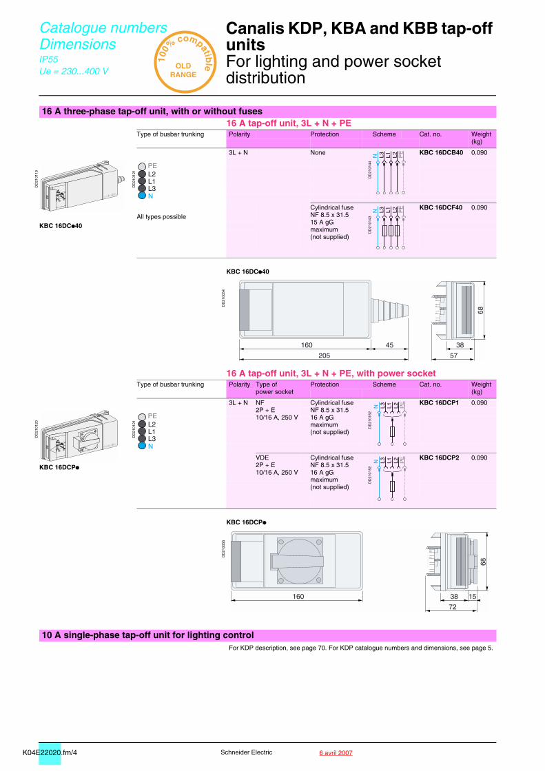
16 A three-phase tap-off unit, with or without fuses16 A tap-off unit, 3L + N + PE
Type of busbar trunking Polarity Protection Scheme Cat. no. Weight(kg)
3L + N None
DD
2101
44
KBC 16DCB40 0.090
DD
2101
19
DD
2101
21
Cylindrical fuseNF 8.5 x 31.515 A gG maximum(not supplied)
DD
2101
43
KBC 16DCF40 0.090All types possible
KBC 16DCp40
KBC 16DCp40
DD
2100
54
16 A tap-off unit, 3L + N + PE, with power socketType of busbar trunking Polarity Type of
power socketProtection Scheme Cat. no. Weight
(kg)
3L + N NF2P + E10/16 A, 250 V
Cylindrical fuseNF 8.5 x 31.516 A gG maximum(not supplied)
DD
2101
52
KBC 16DCP1 0.090
DD
2101
20
DD
2101
21
VDE2P + E10/16 A, 250 V
Cylindrical fuseNF 8.5 x 31.516 A gG maximum(not supplied)
DD
2101
52
KBC 16DCP2 0.090
KBC 16DCPp
KBC 16DCPp
DD
2100
55
123
!
NL3L1L2PE
N L3 L1 L2 PE
123
!
NL3L1L2PE
N L3 L1 L2 PE
160 38
72
68
15
10 A single-phase tap-off unit for lighting controlFor KDP description, see page 70. For KDP catalogue numbers and dimensions, see page 5.
K04E22020.fm/56 avril 2007
Can
alis
KB
C
Schneider Electric
Catalogue numbers Dimensions
Canalis KBA and KBB tap-off units0
For lighting and power socket distribution
IP55Ue = 230...400 V
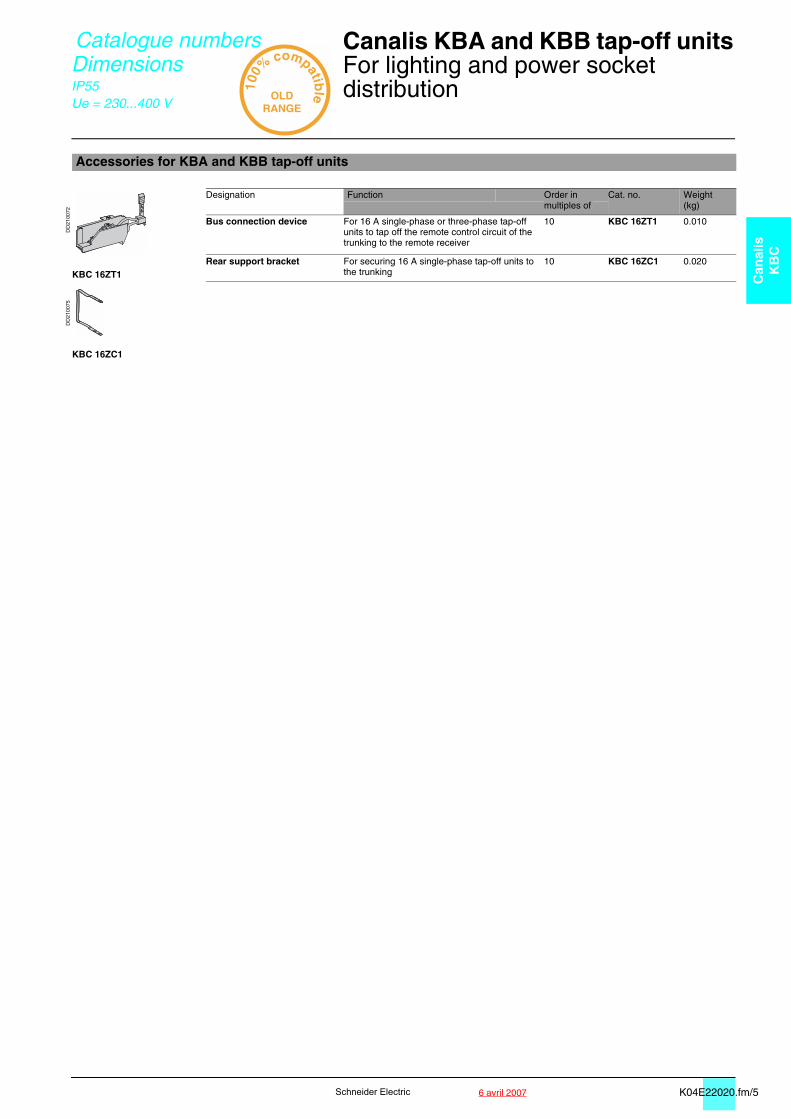
Accessories for KBA and KBB tap-off units
DD
2100
72
Designation Function Order inmultiples of
Cat. no. Weight(kg)
Bus connection device For 16 A single-phase or three-phase tap-off units to tap off the remote control circuit of the trunking to the remote receiver
10 KBC 16ZT1 0.010
Rear support bracket For securing 16 A single-phase tap-off units to the trunking
10 KBC 16ZC1 0.020KBC 16ZT1
DD
2100
75
KBC 16ZC1
K02E31000.fm/2 6 avril 2007Schneider Electric
Installation Canalis KBA, 25 and 40 A 0
Busbar trunking for lighting andpower socket distributionInstallation scenario
IP55Ue = 230...400 VGalvanised or RAL 9010 white
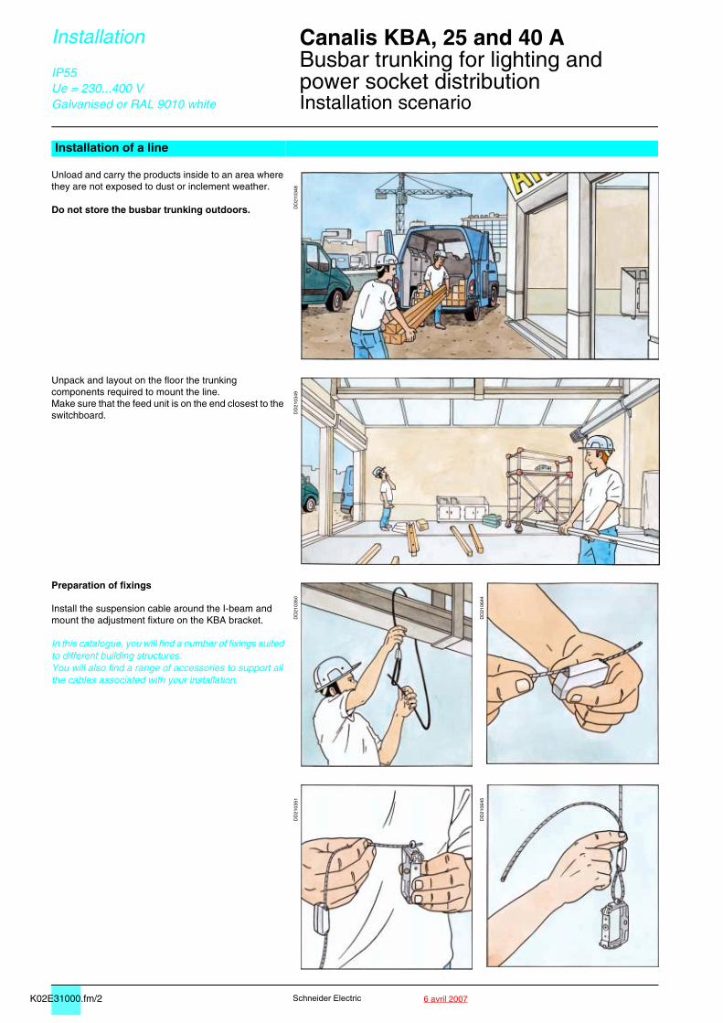
Installation of a line
Unload and carry the products inside to an area where they are not exposed to dust or inclement weather.
Do not store the busbar trunking outdoors. DD
2103
48
Unpack and layout on the floor the trunking components required to mount the line.Make sure that the feed unit is on the end closest to the switchboard. D
D21
0349
Preparation of fixings
Install the suspension cable around the I-beam and mount the adjustment fixture on the KBA bracket.
In this catalogue, you will find a number of fixings suited to different building structures.You will also find a range of accessories to support all the cables associated with your installation.
DD
2103
50
DD
2106
44
DD
2103
51
DD
2106
45
K02E31000.fm/36 avril 2007
Can
alis
KB
A
Schneider Electric
Installation Canalis KBA, 25 and 40 A 0
Busbar trunking for lighting andpower socket distributionInstallation scenario
IP55Ue = 230...400 VGalvanised or RAL 9010 white
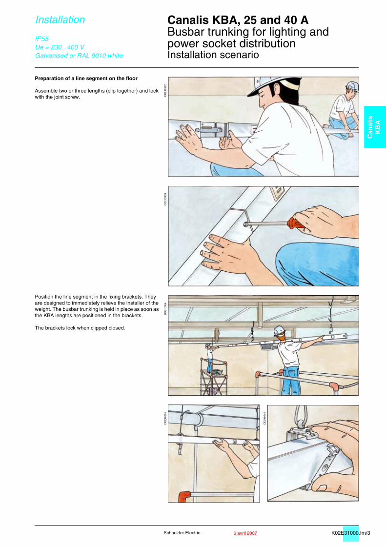
Preparation of a line segment on the floor
Assemble two or three lengths (clip together) and lock with the joint screw. D
D21
0352
DD
2103
53
Position the line segment in the fixing brackets. They are designed to immediately relieve the installer of the weight. The busbar trunking is held in place as soon as the KBA lengths are positioned in the brackets.
The brackets lock when clipped closed.
DD
2103
54D
D21
0355
DD
2106
46
K02E31000.fm/4 6 avril 2007Schneider Electric
Installation Canalis KBA, 25 and 40 A 0
Busbar trunking for lighting andpower socket distributionInstallation scenario
IP55Ue = 230...400 VGalvanised or RAL 9010 white
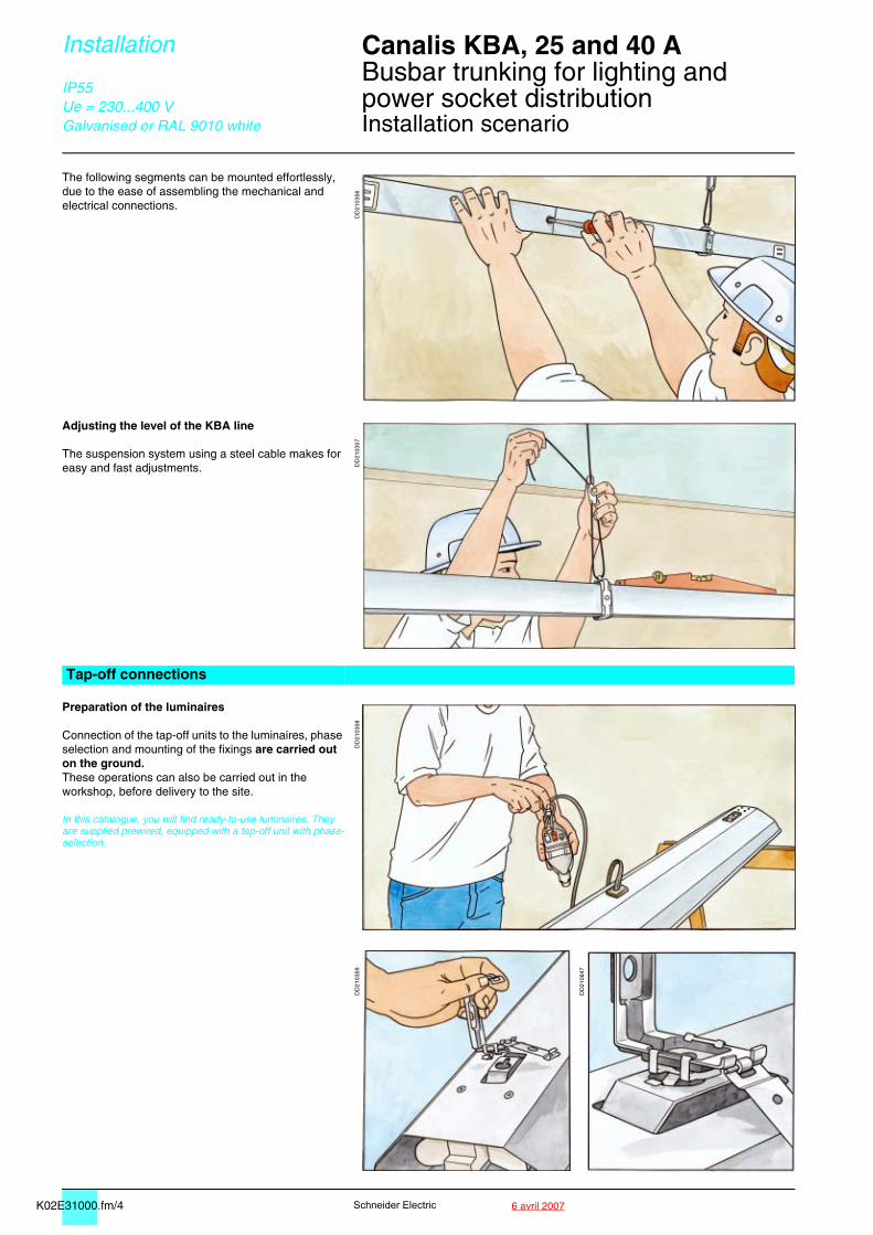
The following segments can be mounted effortlessly, due to the ease of assembling the mechanical and electrical connections.
DD
2103
56
Adjusting the level of the KBA line
The suspension system using a steel cable makes for easy and fast adjustments. D
D21
0357
Tap-off connections
Preparation of the luminaires
Connection of the tap-off units to the luminaires, phase selection and mounting of the fixings are carried out on the ground. These operations can also be carried out in the workshop, before delivery to the site.
In this catalogue, you will find ready-to-use luminaires. They are supplied prewired, equipped with a tap-off unit with phase-selection.
DD
2103
58D
D21
0359
DD
2106
47
K02E31000.fm/56 avril 2007
Can
alis
KB
A
Schneider Electric
Installation Canalis KBA, 25 and 40 A 0
Busbar trunking for lighting andpower socket distributionInstallation scenario
IP55Ue = 230...400 VGalvanised or RAL 9010 white
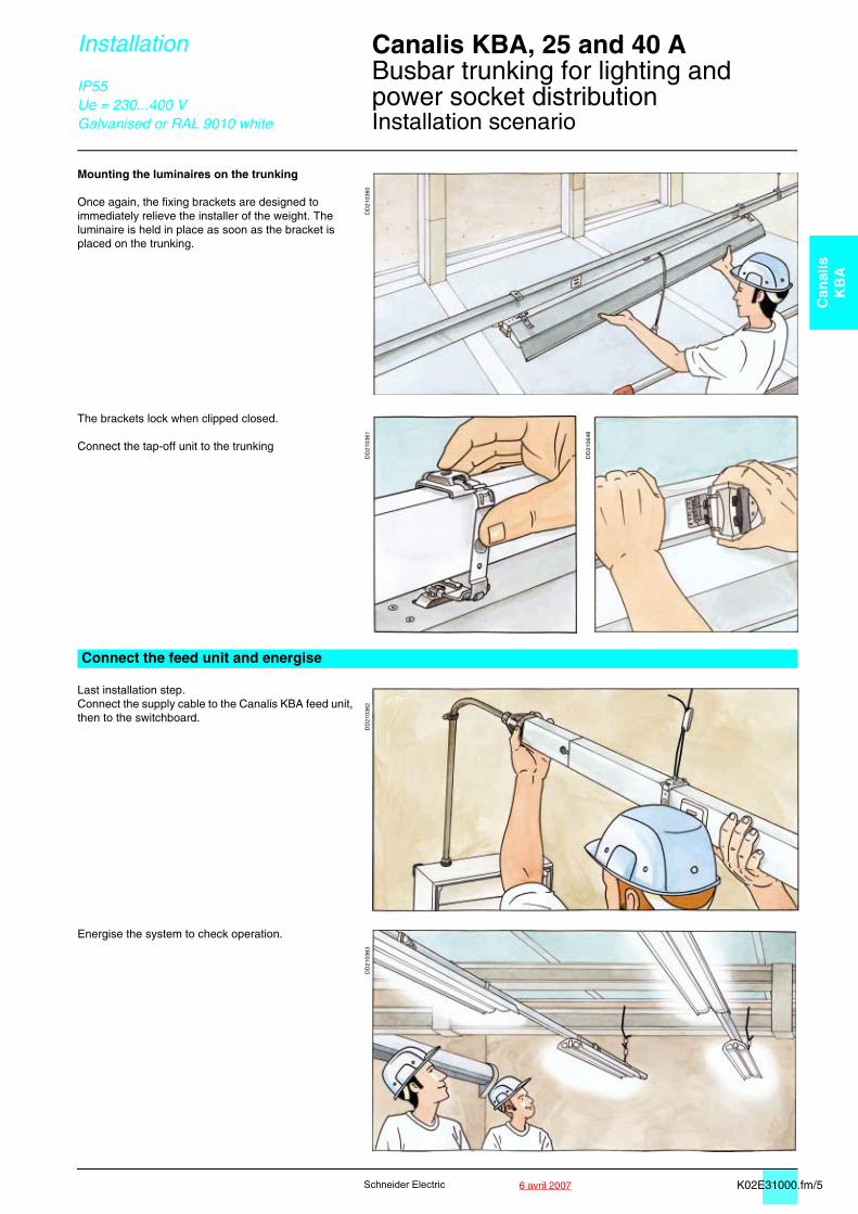
Mounting the luminaires on the trunking
Once again, the fixing brackets are designed to immediately relieve the installer of the weight. The luminaire is held in place as soon as the bracket is placed on the trunking.
DD
2103
60
The brackets lock when clipped closed.
Connect the tap-off unit to the trunking
DD
2103
61
DD
2106
48
Connect the feed unit and energise
Last installation step.Connect the supply cable to the Canalis KBA feed unit, then to the switchboard.
DD
2103
62
Energise the system to check operation.
DD
2103
63
K02E32000.fm/2 6 avril 2007Schneider Electric
Installation Canalis KBA, 25 and 40 A 0
Busbar trunking for lighting andpower socket distributionAssembly of trunking components
IP55Ue = 230...400 VGalvanised or RAL 9010 white
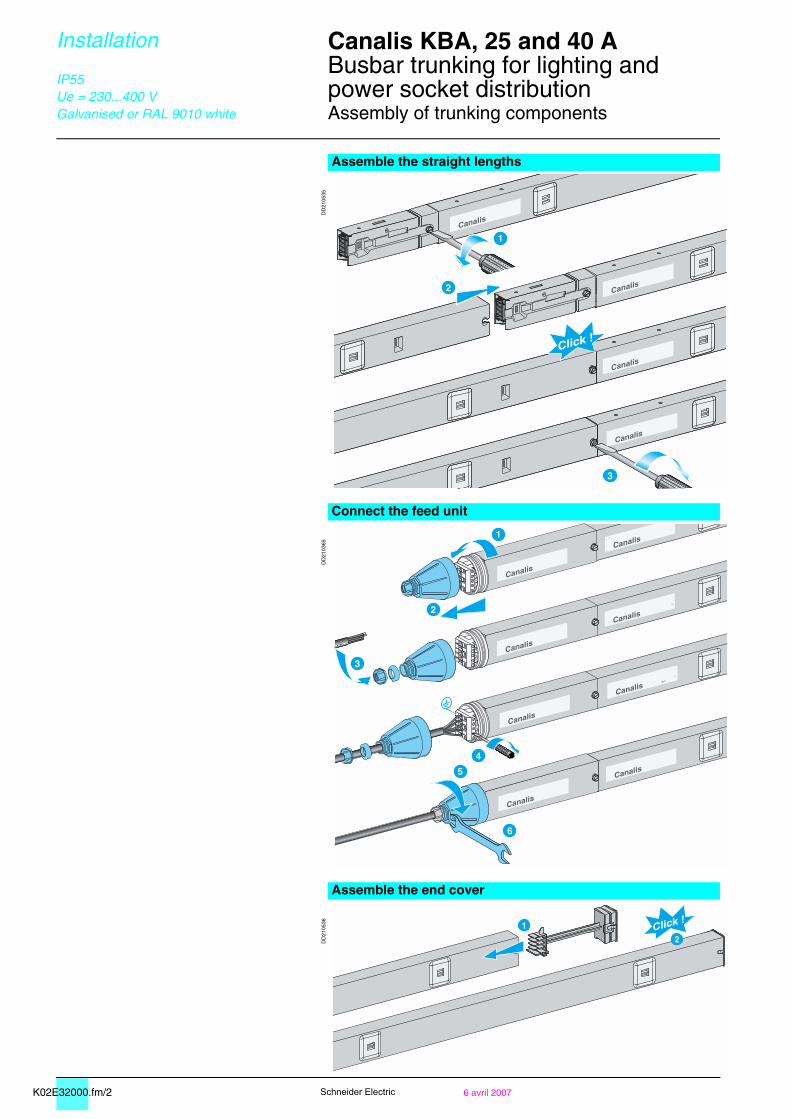
Assemble the straight lengths
DD
2105
35
Connect the feed unit
DD
2103
65
Assemble the end cover
DD
2105
36
Click !
Canalis
Canalis
Canalis
3
2
Canalis
1
3
4
Canalis
Canalis
5
6
Canalis
Canalis
1
2
Canalis
Canalis
Canalis
Canalis
Click !1
2
TDM 05.fm/3
Can
alis
KB
B
Schneider Electric
Contents Canalis KBB 0
PresentationCanalis KBB 116
DescriptionCanalis KBB, 25 and 40 A 120Tap-off units 124
Catalogue numbers / DimensionsCanalis KBB, 25 and 40 A, 1 circuit 126Canalis KBB, 25 and 40 A, 2 circuits 127Tap-off units 130
InstallationInstallation scenario 134Assembly of trunking components 138
K02E32000.fm/36 avril 2007
Can
alis
KB
A
Schneider Electric
Installation Canalis KBA, 25 and 40 A 0
Busbar trunking for lighting andpower socket distributionAssembly of trunking components
IP55Ue = 230...400 VGalvanised or RAL 9010 white
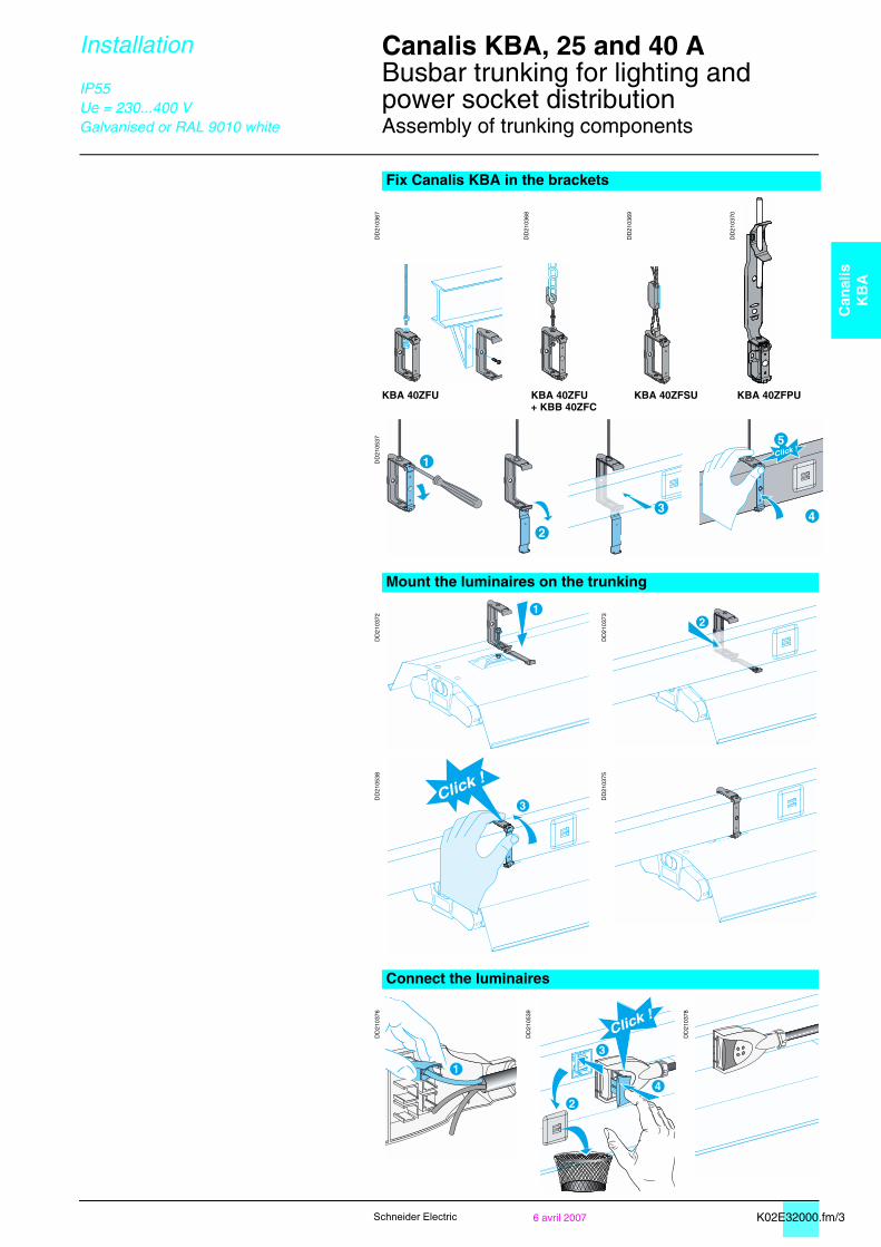
Fix Canalis KBA in the brackets
DD
2103
67
DD
2103
68
DD
2103
69
DD
2103
70
KBA 40ZFU KBA 40ZFU+ KBB 40ZFC
KBA 40ZFSU KBA 40ZFPU
DD
2105
37
Mount the luminaires on the trunking
DD
2103
72
DD
2103
73
DD
2105
38
DD
2103
75
Connect the luminaires
DD
2103
76
DD
2105
39
DD
2103
78
Click !
1
3Click !
1
2
3
4
Click !

TDM 05.fm/2 Schneider Electric
K03E11000.fm/2 Schneider Electric
Presentation Canalis KBB 0
for lighting and power socket distribution
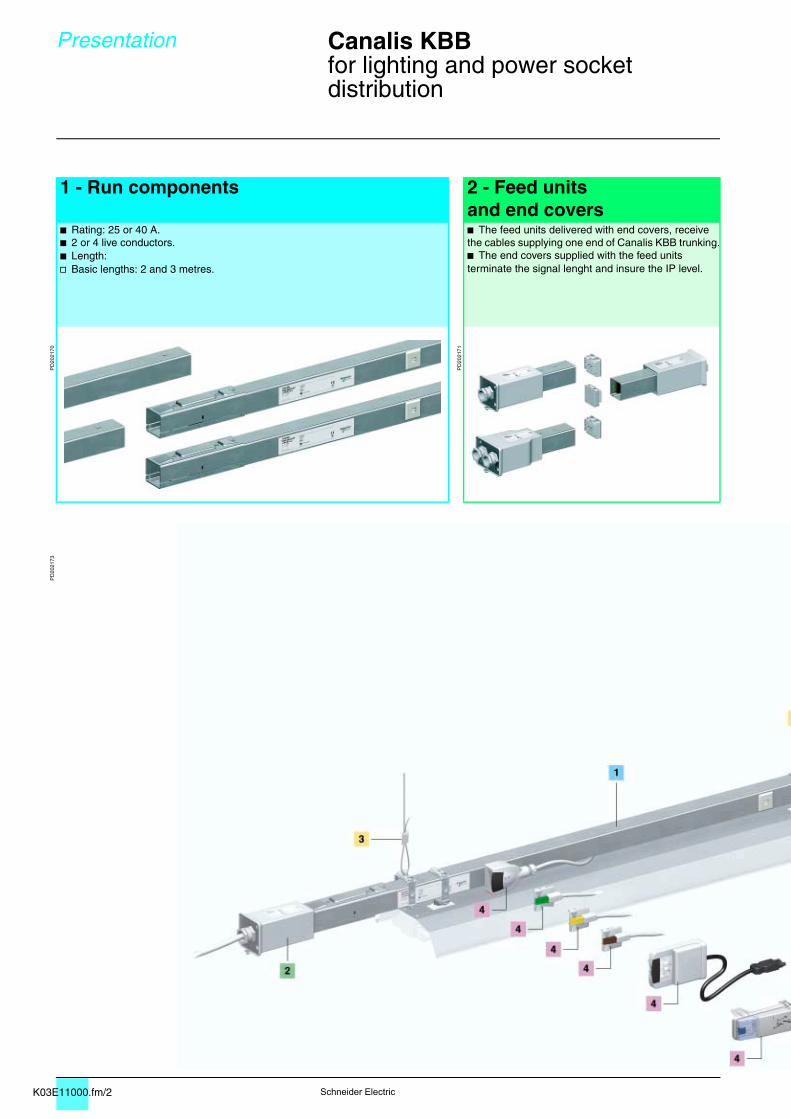
1 - Run components 2 - Feed units
and end coversb Rating: 25 or 40 A.b 2 or 4 live conductors.b Length:v Basic lengths: 2 and 3 metres.
b The feed units delivered with end covers, receive the cables supplying one end of Canalis KBB trunking.b The end covers supplied with the feed units terminate the signal lenght and insure the IP level.
PD
2021
70
PD
2021
71
PD
2021
73
K03E11000.fm/3
Can
alis
KB
B
Schneider Electric
Presentation Canalis KBB 0
for lighting and power socket distribution
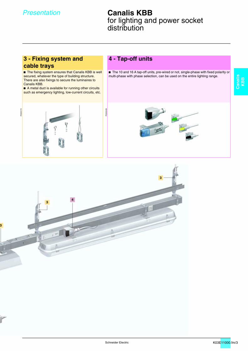
3 - Fixing system and cable trays
4 - Tap-off units
b The fixing system ensures that Canalis KBB is well secured, whatever the type of building structure.There are also fixings to secure the luminaires to Canalis KBB.b A metal duct is available for running other circuits such as emergency lighting, low-current circuits, etc.
b The 10 and 16 A tap-off units, pre-wired or not, single-phase with fixed polarity or multi-phase with phase selection, can be used on the entire lighting range.
PD
2021
72
PD
2024
39
K03E11000.fm/4 Schneider Electric
Presentation Canalis KBB 0
for lighting and power socket distribution
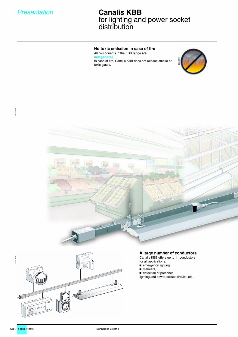
No toxic emission in case of fireAll components in the KBB range are halogen free.In case of fire, Canalis KBB does not release smoke or toxic gases. D
D20
2141
PD
2021
74D
D20
2169
A large number of conductorsCanalis KBB offers up to 11 conductors for all applications:b emergency lighting,b dimmers,b detection of presence,lighting and power-socket circuits, etc.
K03E11000.fm/5
Can
alis
KB
B
Schneider Electric
Presentation Canalis KBB 0
for lighting and power socket distribution
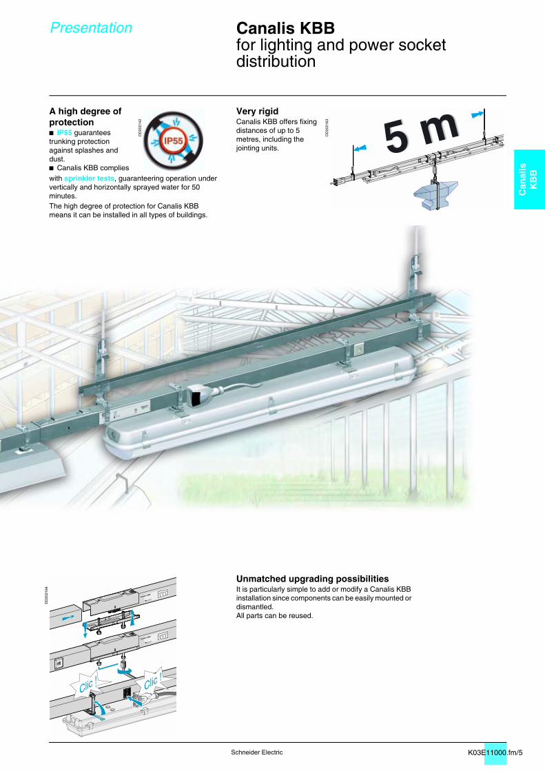
A high degree of protectionb IP55 guarantees trunking protection against splashes and dust.b Canalis KBB complies
DD
2021
42
Very rigidCanalis KBB offers fixing distances of up to 5 metres, including the jointing units.
DD
2021
63
with sprinkler tests, guaranteering operation under vertically and horizontally sprayed water for 50 minutes.The high degree of protection for Canalis KBBmeans it can be installed in all types of buildings.
DD
2021
64
Unmatched upgrading possibilitiesIt is particularly simple to add or modify a Canalis KBB installation since components can be easily mounted or dismantled.All parts can be reused.
K03E12000.fm/2 6 avril 2007Schneider Electric
Description Canalis KBB, 25 and 40 A 0
Busbar trunking for lighting andpower socket distribution
IP55Ue = 230...400 VGalvanised or RAL 9010 white
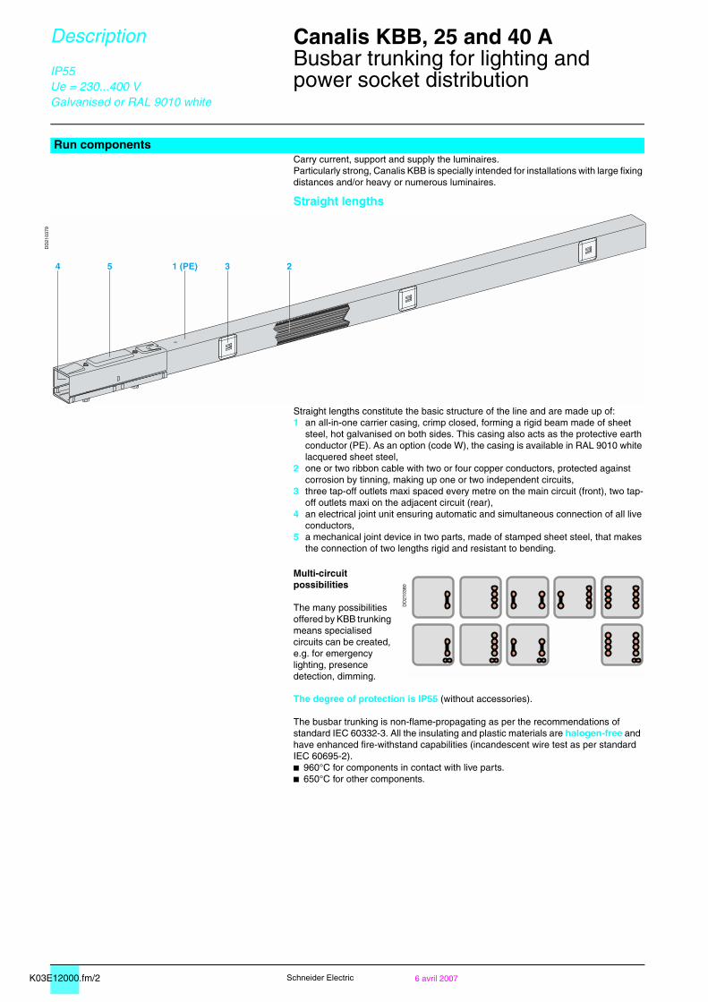
Run componentsCarry current, support and supply the luminaires.Particularly strong, Canalis KBB is specially intended for installations with large fixing distances and/or heavy or numerous luminaires.
Straight lengths
DD
2103
79
Straight lengths constitute the basic structure of the line and are made up of:1 an all-in-one carrier casing, crimp closed, forming a rigid beam made of sheet
steel, hot galvanised on both sides. This casing also acts as the protective earth conductor (PE). As an option (code W), the casing is available in RAL 9010 white lacquered sheet steel,
2 one or two ribbon cable with two or four copper conductors, protected against corrosion by tinning, making up one or two independent circuits,
3 three tap-off outlets maxi spaced every metre on the main circuit (front), two tap-off outlets maxi on the adjacent circuit (rear),
4 an electrical joint unit ensuring automatic and simultaneous connection of all live conductors,
5 a mechanical joint device in two parts, made of stamped sheet steel, that makes the connection of two lengths rigid and resistant to bending.
Multi-circuit possibilities
The many possibilities offered by KBB trunking means specialised circuits can be created, e.g. for emergency lighting, presence detection, dimming.
DD
2103
80
The degree of protection is IP55 (without accessories).
The busbar trunking is non-flame-propagating as per the recommendations of standard IEC 60332-3. All the insulating and plastic materials are halogen-free and have enhanced fire-withstand capabilities (incandescent wire test as per standard IEC 60695-2).b 960°C for components in contact with live parts.b 650°C for other components.
54 1 (PE) 3 2
K03E12000.fm/36 avril 2007
Can
alis
KB
B
Schneider Electric
Description Canalis KBB, 25 and 40 A 0
Busbar trunking for lighting andpower socket distribution
IP55Ue = 230...400 VGalvanised or RAL 9010 white
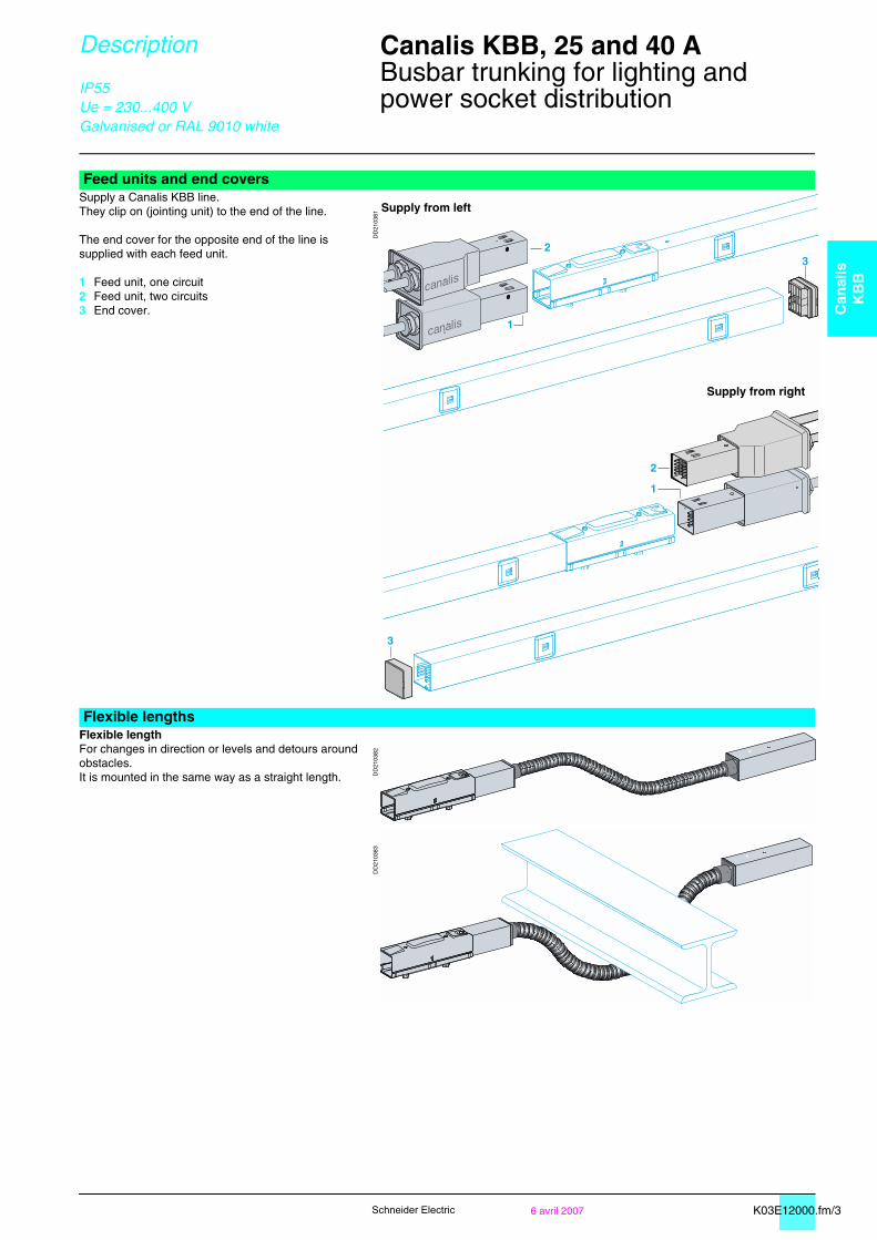
Feed units and end coversSupply a Canalis KBB line.They clip on (jointing unit) to the end of the line.
The end cover for the opposite end of the line is supplied with each feed unit.
1 Feed unit, one circuit2 Feed unit, two circuits3 End cover.
DD
2103
81
Flexible lengthsFlexible lengthFor changes in direction or levels and detours around obstacles.It is mounted in the same way as a straight length. D
D21
0382
DD
2103
83
Supply from left
Supply from right
K03E12000.fm/4 6 avril 2007Schneider Electric
Description Canalis KBB, 25 and 40 A 0
Busbar trunking for lighting andpower socket distribution
IP55Ue = 230...400 VGalvanised or RAL 9010 white
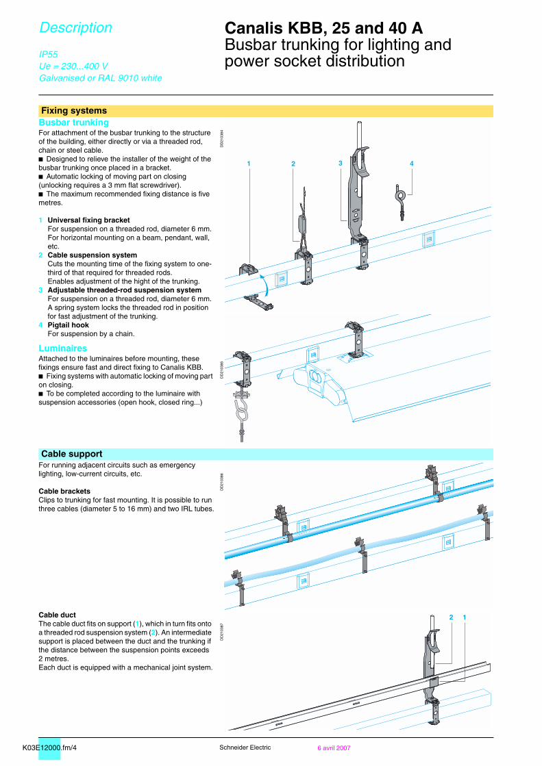
Fixing systemsBusbar trunkingFor attachment of the busbar trunking to the structure of the building, either directly or via a threaded rod, chain or steel cable.b Designed to relieve the installer of the weight of the busbar trunking once placed in a bracket.b Automatic locking of moving part on closing (unlocking requires a 3 mm flat screwdriver).b The maximum recommended fixing distance is five metres.
1 Universal fixing bracketFor suspension on a threaded rod, diameter 6 mm.For horizontal mounting on a beam, pendant, wall, etc.
2 Cable suspension systemCuts the mounting time of the fixing system to one-third of that required for threaded rods.Enables adjustment of the hight of the trunking.
3 Adjustable threaded-rod suspension systemFor suspension on a threaded rod, diameter 6 mm. A spring system locks the threaded rod in position for fast adjustment of the trunking.
4 Pigtail hookFor suspension by a chain.
LuminairesAttached to the luminaires before mounting, these fixings ensure fast and direct fixing to Canalis KBB.b Fixing systems with automatic locking of moving part on closing.b To be completed according to the luminaire with suspension accessories (open hook, closed ring...)
DD
2103
84D
D21
0385
Cable supportFor running adjacent circuits such as emergency lighting, low-current circuits, etc.
Cable bracketsClips to trunking for fast mounting. It is possible to run three cables (diameter 5 to 16 mm) and two IRL tubes.
DD
2103
86
Cable ductThe cable duct fits on support (1), which in turn fits onto a threaded rod suspension system (2). An intermediate support is placed between the duct and the trunking if the distance between the suspension points exceeds 2 metres.Each duct is equipped with a mechanical joint system.
DD
2103
87
42 31
12
K03E12000.fm/56 avril 2007
Can
alis
KB
B
Schneider Electric
Description Canalis KBB, 25 and 40 A 0
Busbar trunking for lighting andpower socket distribution
IP55Ue = 230...400 VGalvanised or RAL 9010 white
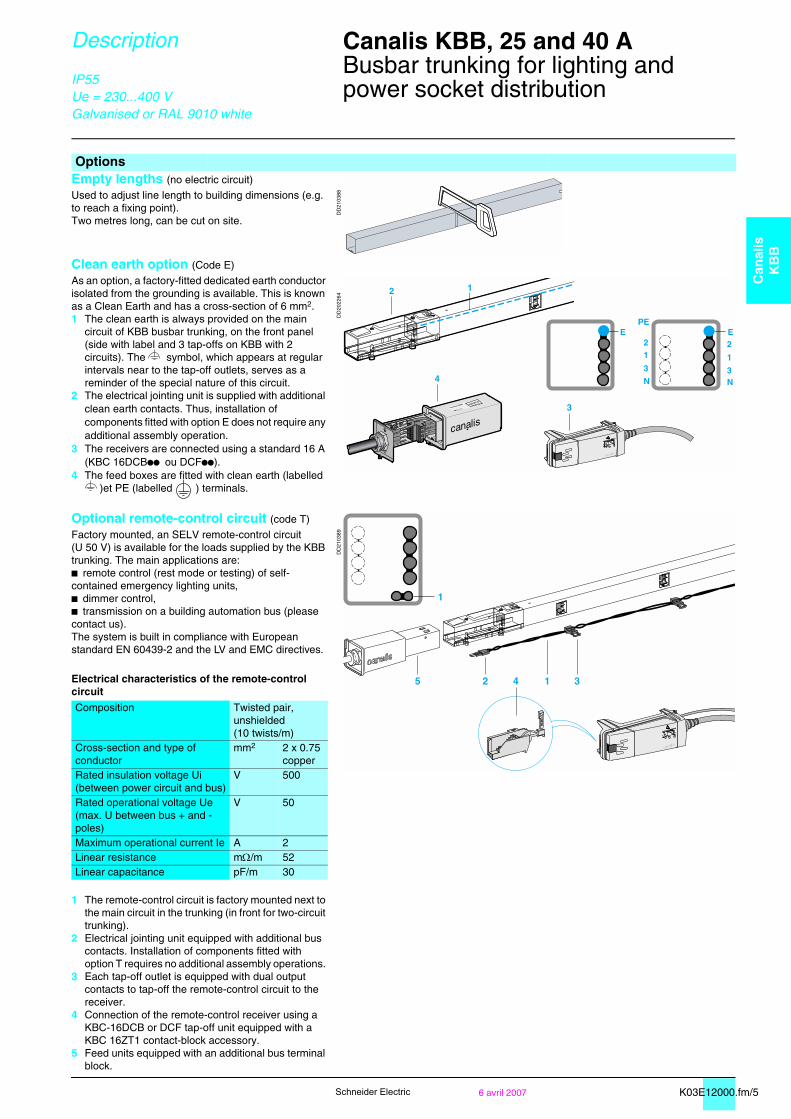
OptionsEmpty lengths (no electric circuit)
DD
2103
88Used to adjust line length to building dimensions (e.g. to reach a fixing point).Two metres long, can be cut on site.
Clean earth option (Code E)
As an option, a factory-fitted dedicated earth conductor isolated from the grounding is available. This is known as a Clean Earth and has a cross-section of 6 mm2.1 The clean earth is always provided on the main
circuit of KBB busbar trunking, on the front panel (side with label and 3 tap-offs on KBB with 2 circuits). The symbol, which appears at regular intervals near to the tap-off outlets, serves as a reminder of the special nature of this circuit.
2 The electrical jointing unit is supplied with additional clean earth contacts. Thus, installation of components fitted with option E does not require any additional assembly operation.
3 The receivers are connected using a standard 16 A (KBC 16DCBpp ou DCFpp).
4 The feed boxes are fitted with clean earth (labelled )et PE (labelled ) terminals.
DD
2022
64
Optional remote-control circuit (code T)
DD
2103
89Factory mounted, an SELV remote-control circuit (U 50 V) is available for the loads supplied by the KBB trunking. The main applications are: b remote control (rest mode or testing) of self-contained emergency lighting units,b dimmer control,b transmission on a building automation bus (please contact us).The system is built in compliance with European standard EN 60439-2 and the LV and EMC directives.
Electrical characteristics of the remote-control circuit
Composition Twisted pair,unshielded(10 twists/m)
Cross-section and type of conductor
mm2 2 x 0.75 copper
Rated insulation voltage Ui(between power circuit and bus)
V 500
Rated operational voltage Ue(max. U between bus + and - poles)
V 50
Maximum operational current Ie A 2Linear resistance mΩ/m 52Linear capacitance pF/m 30
1 The remote-control circuit is factory mounted next to the main circuit in the trunking (in front for two-circuit trunking).
2 Electrical jointing unit equipped with additional bus contacts. Installation of components fitted with option T requires no additional assembly operations.
3 Each tap-off outlet is equipped with dual output contacts to tap-off the remote-control circuit to the receiver.
4 Connection of the remote-control receiver using a KBC-16DCB or DCF tap-off unit equipped with a KBC 16ZT1 contact-block accessory.
5 Feed units equipped with an additional bus terminal block.
1
25 1 34
K04E12020.fm/2 6 avril 2007Schneider Electric
Description Canalis KDP, KBA and KBB 0
Busbar trunking for lighting andpower socket distributionTap-off units
IP55Ue = 230...400 V
DD
2100
68
Tap-off units (general)For instantaneous connection of luminaires to KDP busbar trunking:b they can be handled while energised and under live conditions,b the contacts for live conductors are of the clamp type,b PE connection occurs before that of the phases and neutral,b phase-selection system (clip-in contact studs) for balancing of 3-phase distribution systems,b selection is visible via a transparent window,b a coloured lock holds them in the tap-off outlet,b all the insulating and plastic materials have a high fire-retardant capacity:v incandescent-wire test in compliance with IEC 60695-2-1:
- 960°C for components in contact with live parts,- 650°C for other components.
All the insulators and plastic components are halogen free.
Pre-wired 10 A tap-off unit with fixed polarity
DD
2100
04
Pre-wired with SO5Z1Z1-F 3 x 1.5 mm2 cable, 0.80 m long, pre-stripped on luminaire end:b 10 A rating,b fixed L + N + PE polarity,b the various models make it possible to balance 3-phase distribution systems.
The colour of the lock and the casing enable remote identification of the polarity.1 Live-conductor contacts.2 Protective-conductor contact.3 Lock.
Two-pole 10 A tap-off unit with phase selectionb The two contact studs are movable and can be used to set up both L + N + PE and 2L + PE distribution.b Supplied complete with a cable gland.
DD
2100
83
10 A KBC-10DCB20 tap-off unit, 2-pole + PE, to be wiredb To be wired for connection of luminaires using a cable of specific type, size or length.b Fast connection for 3 x 0.75 to 1.5 mm2 cable. If prefabricated leads are used, the line must have 16 A protection (see possibilities of dispensing with protection in the simplified design guide for lighting distribution, in the section on protection against overloads).
DD
2100
82
10 A KBC tap-off unit, 2-pole + PE, pre-wiredTwo pre-wired versions are available:1 pre-wired with SO5Z1Z1-F 3 x 1.5 mm2 cable, 1 m long, pre-stripped on luminaire
end,2 for KDP, pre-wired with SO5Z1Z1-F 3 x 1.5 mm2 cable, 1 m long and equipped
with a female GST18i3 connector on the luminaire end (see prefabricated leads). In this case, the lead is IP40.
If prefabricated leads are used, the line must have 16 A protection (see possibilities of dispensing with protection in the simplified design guide for lighting distribution, in the section on protection against overloads).
123
!
1
2
K04E12020.fm/36 avril 2007
Can
alis
KB
B
Schneider Electric
Description Canalis KDP, KBA and KBB 0
Busbar trunking for lighting andpower socket distributionTap-off units
IP55Ue = 230...400 V
16 A KBC 16DCB/DCF21 tap-off unit with phase selection
DD
2101
88
For connection of luminaires using a cable of specific type, size and length.
b Two-pole: L + N + PE (1 mobile stud, fixed neutral) or 2L + PE (2 mobile studs). b Installation is facilitated by the side guides. b Supplied with a cable bushing. Terminal connections for 0.75 to 1.5 mm2 cable.
KBC 16DCB tap-off unit with terminals, direct connection (no protection)For direct connection (no protection) of luminaires using a specific cable.Can be equipped with the accessory to tap-off the remote-control circuit to the luminaires.
KBC 16DCF tap-off unit, with fusesFor protection of each luminaire.Fuse carrier on the phase (1 or 2 carriers depending on the model).For cylindrical fuse NF 8.5 x 31.5 (not supplied), 16 A gG maximum, breaking capacity 20 kA.
16 A L + N + PE tap-off unit with preselected polarityKBC 16DCB/DCFpp6
DD
2101
89
For tap-off and individual protection of luminaires assigned to two independent circuits of 4-conductor KBB trunking.Identical in design to the tap-off units on the opposite page, but with factory-set polarity.
Accessories
DD
2101
90
Specific to KBC 16DCF tap-off units1 Additional remote-control contact blockb For tap-off of the remote-control circuit to the luminaire (KBA and KBB lines with T option).b Clips onto KBC 16DCB or CF (except KBC 16DCF22) tap-off units.b Terminals for data cable, max. size 2 X 0.75 mm2. b Supplied with cable bushing.
2 Rear support bracketAdditional fixing of KBC 16 tap-off units using the rear support bracket may be necessary, notably if there is a risk of accidental pulling on the cable or if the cable is very heavy (great length).
Other accessories3 Interlocking device For all 10 A and 16 A tap-off units.A set of three interlocking devices in different colours can be used to mechanically lock out tap-off units when two or three different distribution networks are present (load, voltage, frequency, etc.).b An interlocking device is made up of a handle and an interlocking device on each end. It can be used for a tap-off outlet and the corresponding tap-off unit.b Labels can be placed on the tap-off units and the trunking for remote identification.
4 Outlet blanking plateSpare part intended to restore IP55 on a tap-off outlet following removal of the tap-off unit (if original blanking plate is lost).
DD
2101
91D
D21
0192
123
!
1
2
123
!
3
4
K03E21000.fm/2 Schneider Electric
Catalogue numbers Dimensions
Canalis KBB, 25 and 40 A, 1 circuit0
Busbar trunking for lighting andpower socket distributionOptional remote-control circuit (code T)Optional white-lacquered metal enclosure (code W)Optional isolated earth (code E)
IP55Ue = 230...400 VGalvanised or RAL 9010 white
Straight lengths, one circuit
DD
2100
88
Type ofbusbar trunking
Length (m)
Numberoftap-offs
Order in multiples of(2)
25 A rating Weight(kg)
40 A rating Weight(kg)
Option(1)
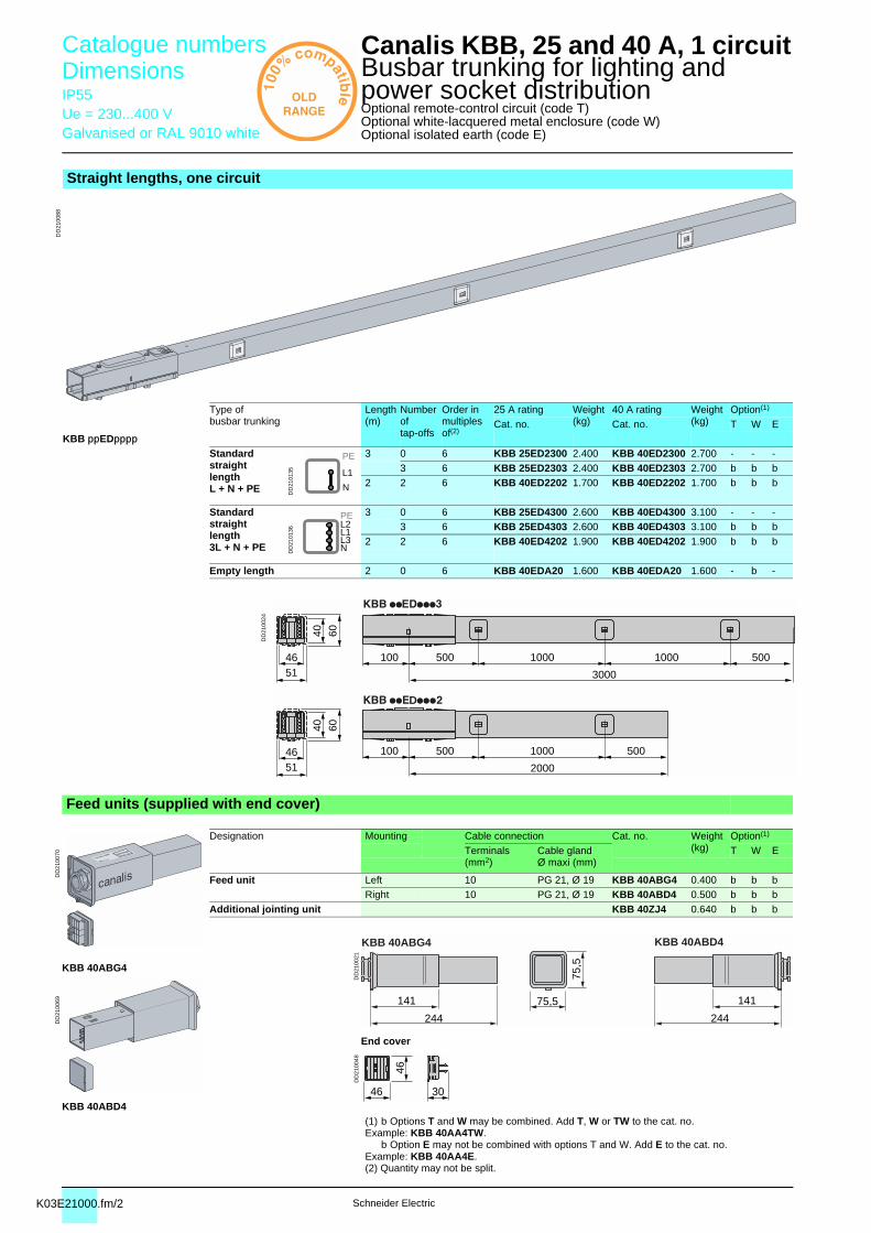
Cat. no. Cat. no. T W EKBB ppEDpppp
Standard straight lengthL + N + PE D
D21
0135
3 0 6 KBB 25ED2300 2.400 KBB 40ED2300 2.700 - - -3 6 KBB 25ED2303 2.400 KBB 40ED2303 2.700 b b b
2 2 6 KBB 40ED2202 1.700 KBB 40ED2202 1.700 b b b
Standard straight length3L + N + PE D
D21
0136
3 0 6 KBB 25ED4300 2.600 KBB 40ED4300 3.100 - - -3 6 KBB 25ED4303 2.600 KBB 40ED4303 3.100 b b b
2 2 6 KBB 40ED4202 1.900 KBB 40ED4202 1.900 b b b
Empty length 2 0 6 KBB 40EDA20 1.600 KBB 40EDA20 1.600 - b -
DD
2100
24
Feed units (supplied with end cover)
DD
2100
70
Designation Mounting Cable connection Cat. no. Weight(kg)
Option(1)
Terminals(mm2)
Cable glandØ maxi (mm)
T W E
Feed unit Left 10 PG 21, Ø 19 KBB 40ABG4 0.400 b b bRight 10 PG 21, Ø 19 KBB 40ABD4 0.500 b b b
Additional jointing unit KBB 40ZJ4 0.640 b b b
DD
2100
21
KBB 40ABG4
DD
2100
69
DD
2100
48
End cover
KBB 40ABD4(1) b Options T and W may be combined. Add T, W or TW to the cat. no.Example: KBB 40AA4TW.
b Option E may not be combined with options T and W. Add E to the cat. no. Example: KBB 40AA4E.(2) Quantity may not be split.
N
L1
PE
N
L1L2
L3
PE
2000
51
60
46
40
500100 500
3000
500 1000
1000
100 1000 500
51
60
46
40
D
KBB 40ABG4 KBB 40ABD4
75,5 141
75,5
244
141
244
46 30
46
K03E21000.fm/3
Can
alis
KB
B
Schneider Electric
Canalis KBB, 25 and 40 A, 2 circuits0
Busbar trunking for lighting andpower socket distributionOptional remote-control circuit (code T)Optional white-lacquered metal enclosure (code W)Optional isolated earth (code E)
Straight lengths, two circuits
DD
2100
89
Type ofbusbar trunking
Length(m)
Numberoftap-offs
Order in multiples of(3)
25 A rating Weight(kg)
40 A rating Weight(kg)
Option(1)
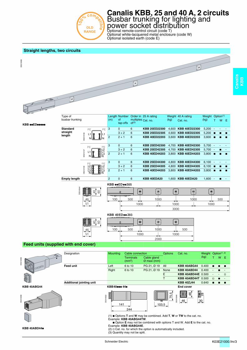
Cat. no. Cat. no. T W EKBB ppEDppppp
Standardstraightlength
DD
2101
08
3 0 6 KBB 25ED22300 4,600 KBB 40ED22300 5,200 - - -3 + 2 6 KBB 25ED22305 4,600 KBB 40ED22305 5,200 b b b
2 2 + 1 6 KBB 40ED22203 3,600 KBB 40ED22203 3,600 b b b
DD
2101
07
3 0 6 KBB 25ED42300 4,700 KBB 40ED42300 5,700 - - -3 + 2 6 KBB 25ED42305 4,700 KBB 40ED42305 5,700 - b -
2 2 + 1 6 KBB 40ED44203 3,800 KBB 40ED44203 3,800 b b b
DD
2101
09
3 0 6 KBB 25ED44300 4,800 KBB 40ED44300 6,100 - - -3 + 2 6 KBB 25ED44305 4,800 KBB 40ED44305 6,100 b b b
2 2 + 1 6 KBB 40ED44203 3,800 KBB 40ED44203 3,800 b b b
Empty length 2 0 6 KBB 40EDA20 1,600 KBB 40EDA20 1,600 - b -
DD
2100
44
Feed units (supplied with end cover)
DD
2100
99
Designation Mounting Cable connection Options Cat. no. Weight(kg)
Option(1, 2)
Terminals(mm2)
Cable glandØ maxi (mm)
T W E
Feed unit Left 6 to 10 PG 21, Ø 19 All KBB 40ABG44 0.400 b b bRight 6 to 10 PG 21, Ø 19 None KBB 40ABD44 0.400 - b -
E KBB 40ABD44E 0.500 - - vT KBB 40ABD44T 0.500 v b -
Additional jointing unit KBB 40ZJ44 0.640 b b bKBB 40ABG44 KBB 40ppp 44p End cover
DD
2100
98
DD
2100
22
DD
2100
48
(1) b Options T and W may be combined. Add T, W or TW to the cat. no.Example: KBB 40ABG44TW.
b Option E may not be combined with options T and W. Add E to the cat. no.Example: KBB 40ABG44E.(2) v Cat. no. for which the option is automatically included.(3) Quantity may not be split.
KBB 40ABD44p
N
L1
PE
N
L1
PE
N
L1
PE
N
L1L2
L3
PE
N
L1L2
L3
PE
N
L1L2
L3
PE
103,5
75,5
141
244
46 30
46
K03E21000.fm/4 6 avril 2007Schneider Electric
Catalogue numbers Dimensions
Canalis KBB, 25 and 40 A 0
Busbar trunking for lighting andpower socket distributionOptional remote-control circuit (code T)Optional white-lacquered metal enclosure (code W)Optional isolated earth (code E)
IP55Ue = 230...400 VGalvanised or RAL 9010 white
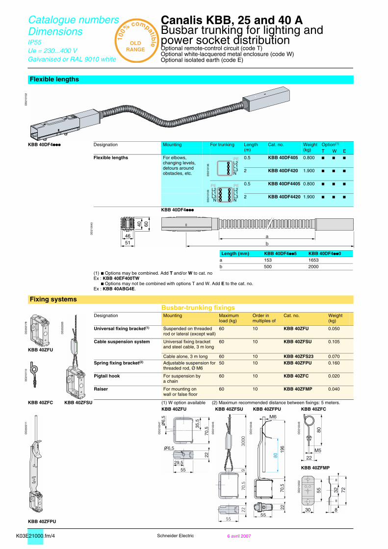
Flexible lengths
DD
2101
02
KBB 40DF4ppp Designation Mounting For trunking Length(m)
Cat. no. Weight(kg)
Option(1)
T W EFlexible lengths For elbows,
changing levels,detours around obstacles, etc. D
D21
0136
0.5 KBB 40DF405 0.800 b b b
2 KBB 40DF420 1.900 b b b
DD
2101
09
0.5 KBB 40DF4405 0.800 b b b
2 KBB 40DF4420 1.900 b b b
KBB 40DF4ppp
DD
2100
43
Length (mm) KBB 40DF4pp5 KBB 40DF4pp0a 153 1653b 500 2000
(1) b Options may be combined. Add T and/or W to cat. no Ex : KBB 40EF400TW .
b Options may not be combined with options T and W. Add E to the cat. no.Ex : KBB 40ABG4E.
Fixing systemsBusbar-trunking fixings
DD
2021
78
DD
2022
65
Designation Mounting Maximumload (kg)
Order in multiples of
Cat. no. Weight(kg)
Universal fixing bracket(1) Suspended on threadedrod or lateral (except wall)
60 10 KBB 40ZFU 0.050
Cable suspension system Universal fixing bracket and steel cable, 3 m long
60 10 KBB 40ZFSU 0.105
KBB 40ZFUCable alone, 3 m long 60 10 KBB 40ZFS23 0.070
DD
2101
10
Spring fixing bracket(2) Adjustable suspension for threaded rod, Ø M6
50 10 KBB 40ZFPU 0.160
Pigtail hook For suspension bya chain
60 10 KBB 40ZFC 0.020
Raiser For mounting onwall or false floor
60 10 KBB 40ZFMP 0.040
KBB 40ZFC KBB 40ZFSU (1) W option available (2) Maximun recommended distance between fixings: 5 meters.KBB 40ZFU KBB 40ZFSU KBB 40ZFPU KBB 40ZFC
DD
2022
11
DD
2100
47
DD
2100
45
DD
2100
46
DD
2100
49
KBB 40ZFMP
DD
2100
50
KBB 40ZFPU
N
L1L2
L3
PE
N
L1L2
L3
PE
N
L1L2
L3
PE
b
a51
60
46
40
35,5
K03E21000.fm/56 avril 2007
Can
alis
KB
B
Schneider Electric
Catalogue numbers Dimensions
Canalis KBB, 25 and 40 A 0
Busbar trunking for lighting andpower socket distributionOptional white-lacquered metal enclosure (code W)
IP55Ue = 230...400 VGalvanised or RAL 9010 white
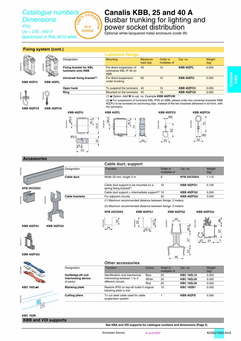
Fixing system (cont.)Luminaire fixings
DD
2021
78
DD
2050
31
Designation Mounting Maximumload (kg)
Order in multiples of
Cat. no. Weight(kg)
Fixing bracket for KBL luminaire onto KBB
For direct suspension of luminaires KBL IP 20 on KBB
45 12 KBB 40ZFL 0.055
Universal fixing bracket(1) For direct suspension under trunking
60 10 KBB 40ZFU 0.050KBB 40ZFU KBB 40ZFL
DD
2101
01
DD
2101
00
Open hook To suspend the luminaire 45 10 KBB 40ZFC5 0.050Ring Mounted on the luminaire 45 10 KBB 40ZFC6 0.050
(1) b Option: Add W to cat. no. Example KBB 40ZFUW.(2) b For suspension of luminaire KBL IP55 on KBB, please order two universal brackets KBB 40ZFU to be screwed on anchoring clips, instead of the two brackets delivered in kit form, with the luminaire. KBB 40ZFC5 KBB 40ZFC6
KBB 40ZFU KBB 40ZFL KBB 40ZFC5 KBB 40ZFC6
DD
2100
47
DD
2050
32
DD
2210
041
DD
2100
40
Accessories
DD
2100
97
Cable duct, supportDesignation Function Order in
multiples ofCat. no. Weight
(kg)
Cable duct Width 25 mm, length 3 m 6 KFB 25CD253 1.115
KFB 25CD253Cable duct support to be mounted on aspring fixing bracket(1)
10 KBB 40ZFG1 0.100
DD
2103
15
DD
2103
16
Cable duct support + intermediate support(2) 10 KBB 40ZFG2 0.200Cable brackets For adjacent circuits 20 KBB 40ZFGU 0.005
(1) Maximun recommended distance between fixings: 2 meters.
(2) Maximun recommended distance between fixings: 3 meters.
KFB 25CD253 KBB 40ZFG1 KBB 40ZFG2 KBB 40ZFGU
DD
2100
38
DD
2022
94
DD
2022
61
DD
2100
39
KBB 40ZFG1 KBB 40ZFG2
DD
2101
11
KBB 40ZFGU
DD
2100
85
Other accessoriesDesignation Function Colour Order in
multiples ofCat. no. Weight
(kg)Outlet/tap-off unit interlocking device(2 parts)
Identification and mechanical interlocking between 1 to 3 different circuits
Blue 20 KBC 16ZL10 0.002White 20 KBC 16ZL20 0.002Red 20 KBC 16ZL30 0.002
KBC 16ZLp0 Blanking plate Restore IP55 on tap-off outlet if original blanking plate is lost
10 KBC 16ZB1 0.005
DD
2101
31 Cutting pliers To cut steel cable used for cablesuspension system
1 KBB 40ZFS 0.300
KBC 16ZB
KBB and VDI supports See KBA and VDI supports for catalogue numbers and dimensions (Page 5)
35,5
74
30
Ø6.
5
35,5
25
25
25
46
28,5
4722
51 727
3857
K04E22030.fm/2 6 avril 2007Schneider Electric
Catalogue numbers Dimensions
Canalis KDP, KBA and KBB tap-off units 0
For lighting and power socket distribution
IP55Ue = 230...400 V
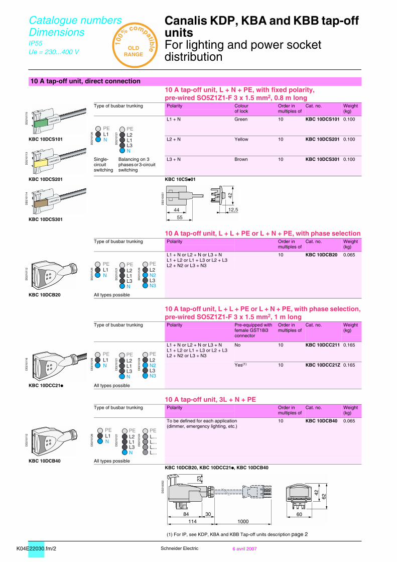
10 A tap-off unit, direct connection10 A tap-off unit, L + N + PE, with fixed polarity,pre-wired SO5Z1Z1-F 3 x 1.5 mm2, 0.8 m long
DD
2101
15
Type of busbar trunking Polarity Colourof lock
Order inmultiples of
Cat. no. Weight(kg)
L1 + N Green 10 KBC 10DCS101 0.100
DD
2101
26
DD
2101
21
KBC 10DCS101 L2 + N Yellow 10 KBC 10DCS201 0.100
DD
2101
13
Single-circuit switching
Balancing on 3 phases or 3-circuit switching
L3 + N Brown 10 KBC 10DCS301 0.100
KBC 10DCS201 KBC 10CSp01
DD
2101
14
DD
2100
51
KBC 10DCS301
10 A tap-off unit, L + L + PE or L + N + PE, with phase selectionType of busbar trunking Polarity Order in
multiples ofCat. no. Weight
(kg)
L1 + N or L2 + N or L3 + NL1 + L2 or L1 + L3 or L2 + L3L2 + N2 or L3 + N3
10 KBC 10DCB20 0.065
DD
2101
12
DD
2101
26
DD
2101
21
DD
2101
28
KBC 10DCB20 All types possible
10 A tap-off unit, L + L + PE or L + N + PE, with phase selection,pre-wired SO5Z1Z1-F 3 x 1.5 mm2, 1 m long
Type of busbar trunking Polarity Pre-equipped withfemale GST18i3connector
Order inmultiples of
Cat. no. Weight(kg)
L1 + N or L2 + N or L3 + NL1 + L2 or L1 + L3 or L2 + L3L2 + N2 or L3 + N3
No 10 KBC 10DCC211 0.165
DD
2101
16
DD
2101
26
DD
2101
21
DD
2101
28
Yes(1) 10 KBC 10DCC21Z 0.165
KBC 10DCC21p All types possible
10 A tap-off unit, 3L + N + PEType of busbar trunking Polarity Order in
multiples ofCat. no. Weight
(kg)
To be defined for each application(dimmer, emergency lighting, etc.)
10 KBC 10DCB40 0.065
DD
2101
12
DD
2101
26
DD
2101
21
DD
2101
24
KBC 10DCB40 All types possibleKBC 10DCB20, KBC 10DCC21p, KBC 10DCB40
DD
2100
52
(1) For IP, see KDP, KBA and KBB Tap-off units description page 2
NL1PE
NL3L1L2PE
44
55
12,5
42
NL1PE
NL3L1L2PE
L3N3
N2L2PE
NL1PE
NL3L1L2PE
L3N3
N2L2PE
NL1PE
NL3L1L2PE
L...L...L...L...PE
23
62
114 1000
84 30 60
42
K04E22030.fm/36 avril 2007
Can
alis
KB
C
Schneider Electric
Catalogue numbers Dimensions
Canalis KDP, KBA and KBB tap-off units 0
For lighting and power socket distribution
IP55Ue = 230...400 V
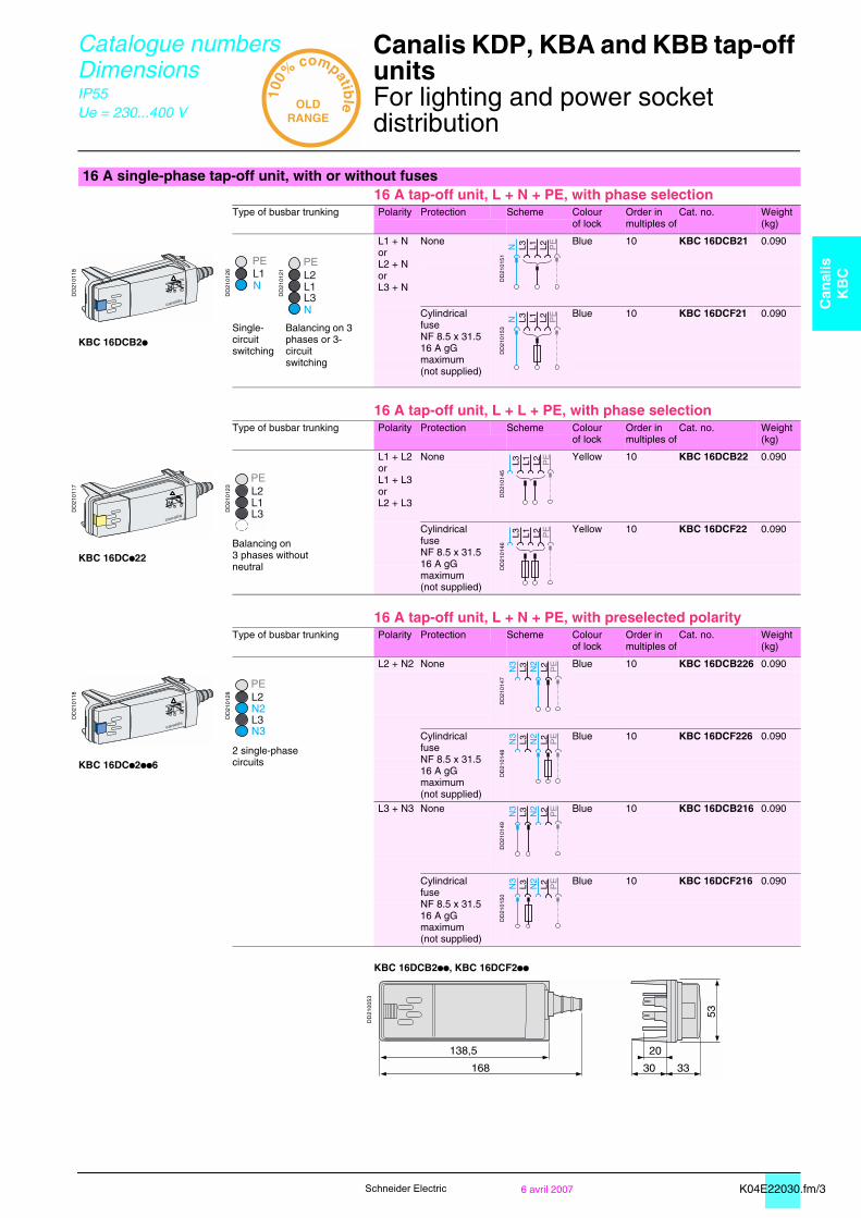
16 A single-phase tap-off unit, with or without fuses16 A tap-off unit, L + N + PE, with phase selection
Type of busbar trunking Polarity Protection Scheme Colourof lock
Order inmultiples of
Cat. no. Weight(kg)
L1 + NorL2 + NorL3 + N
None
DD
2101
51
Blue 10 KBC 16DCB21 0.090
DD
2101
18
DD
2101
26
DD
2101
21
Cylindrical fuseNF 8.5 x 31.516 A gG maximum(not supplied)
DD
2101
53
Blue 10 KBC 16DCF21 0.090Single-circuit switching
Balancing on 3 phases or 3-circuit switching
KBC 16DCB2p
16 A tap-off unit, L + L + PE, with phase selectionType of busbar trunking Polarity Protection Scheme Colour
of lockOrder inmultiples of
Cat. no. Weight(kg)
L1 + L2orL1 + L3orL2 + L3
None
DD
2101
45
Yellow 10 KBC 16DCB22 0.090
DD
2101
17
DD
2101
23
Cylindrical fuseNF 8.5 x 31.516 A gG maximum(not supplied)
DD
2101
46
Yellow 10 KBC 16DCF22 0.090Balancing on3 phases without neutral
KBC 16DCp22
16 A tap-off unit, L + N + PE, with preselected polarityType of busbar trunking Polarity Protection Scheme Colour
of lockOrder inmultiples of
Cat. no. Weight(kg)
L2 + N2 None
DD
2101
47
Blue 10 KBC 16DCB226 0.090
DD
2101
18
DD
2101
28
Cylindrical fuseNF 8.5 x 31.516 A gG maximum(not supplied)
DD
2101
48
Blue 10 KBC 16DCF226 0.0902 single-phase circuits
KBC 16DCp2pp6
L3 + N3 None
DD
2101
49
Blue 10 KBC 16DCB216 0.090
Cylindrical fuseNF 8.5 x 31.516 A gG maximum(not supplied)
DD
2101
50
Blue 10 KBC 16DCF216 0.090
KBC 16DCB2pp, KBC 16DCF2pp
DD
2100
53
N L3 L1 L2 PE
123
!
NL1PE
NL3L1L2PE
N L3 L1 L2 PE
123
!
L3L1L2PE
N3
L3 N2
L2 PE
123
!
L3N3
N2L2PE
N3
L3 N2
L2 PE
N3
L3 N2
L2 PE
N3
L3 N2
L2 PE

K04E22030.fm/4 6 avril 2007Schneider Electric
Catalogue numbers Dimensions
Canalis KDP, KBA and KBB tap-off units 0
For lighting and power socket distribution
IP55Ue = 230...400 V
16 A three-phase tap-off unit, with or without fuses16 A tap-off unit, 3L + N + PE
Type of busbar trunking Polarity Protection Scheme Cat. no. Weight(kg)
3L + N None
DD
2101
44
KBC 16DCB40 0.090
DD
2101
19
DD
2101
21
Cylindrical fuseNF 8.5 x 31.515 A gG maximum(not supplied)
DD
2101
43
KBC 16DCF40 0.090All types possible
KBC 16DCp40
KBC 16DCp40
DD
2100
54
16 A tap-off unit, 3L + N + PE, with power socketType of busbar trunking Polarity Type of
power socketProtection Scheme Cat. no. Weight
(kg)
3L + N NF2P + E10/16 A, 250 V
Cylindrical fuseNF 8.5 x 31.516 A gG maximum(not supplied)
DD
2101
52
KBC 16DCP1 0.090
DD
2101
20
DD
2101
21
VDE2P + E10/16 A, 250 V
Cylindrical fuseNF 8.5 x 31.516 A gG maximum(not supplied)
DD
2101
52
KBC 16DCP2 0.090
KBC 16DCPp
KBC 16DCPp
DD
2100
55
123
!
NL3L1L2PE
N L3 L1 L2 PE
123
!
NL3L1L2PE
N L3 L1 L2 PE
160 38
72
68
15
10 A single-phase tap-off unit for lighting controlFor KDP description, see page 70. For KDP catalogue numbers and dimensions, see page 79.

K04E22030.fm/56 avril 2007
Can
alis
KB
C
Schneider Electric
Catalogue numbers Dimensions
Canalis KBA and KBB tap-off units0
For lighting and power socket distribution
IP55Ue = 230...400 V
Accessories for KBA and KBB tap-off units
DD
2100
72
Designation Function Order inmultiples of
Cat. no. Weight(kg)
Bus connection device For 16 A single-phase or three-phase tap-off units to tap off the remote control circuit of the trunking to the remote receiver
10 KBC 16ZT1 0.010
Rear support bracket For securing 16 A single-phase tap-off units to the trunking
10 KBC 16ZC1 0.020KBC 16ZT1
DD
2100
75
KBC 16ZC1
K03E31000.fm/2 6 avril 2007Schneider Electric
Installation Canalis KBB, 25 and 40 A 0
Busbar trunking for lighting andpower socket distributionInstallation scenario
IP55Ue = 230...400 VGalvanised or RAL 9010 white
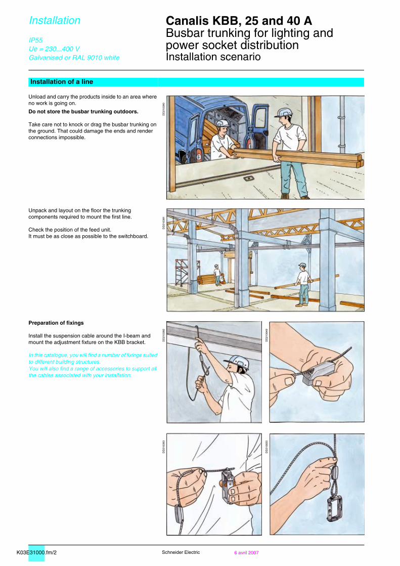
Installation of a line
Unload and carry the products inside to an area where no work is going on.
Do not store the busbar trunking outdoors.
Take care not to knock or drag the busbar trunking on the ground. That could damage the ends and render connections impossible.
DD
2103
90
Unpack and layout on the floor the trunking components required to mount the first line.
Check the position of the feed unit.It must be as close as possible to the switchboard.
DD
2103
91
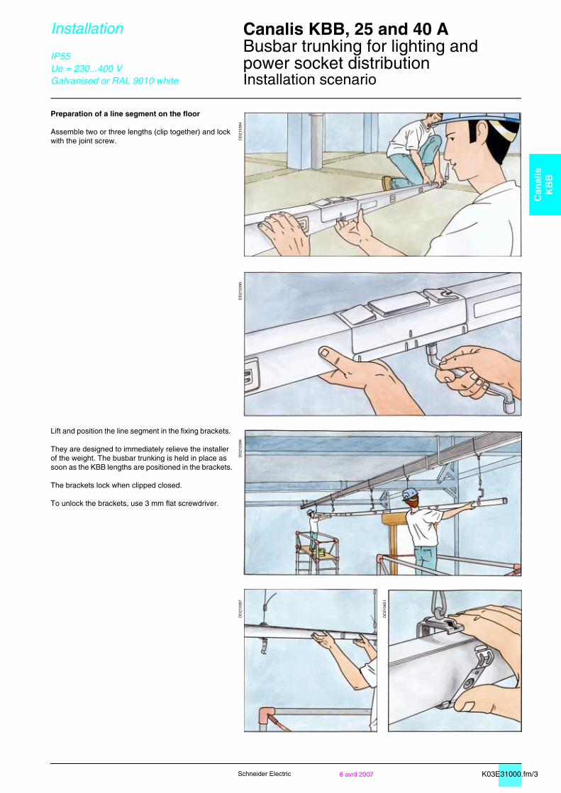
Preparation of fixings
Install the suspension cable around the I-beam and mount the adjustment fixture on the KBB bracket.
In this catalogue, you will find a number of fixings suited to different building structures.You will also find a range of accessories to support all the cables associated with your installation.
DD
2103
92
DD
2106
49
DD
2103
93
DD
2106
50
K03E31000.fm/36 avril 2007
Can
alis
KB
B
Schneider Electric
Installation Canalis KBB, 25 and 40 A 0
Busbar trunking for lighting andpower socket distributionInstallation scenario
IP55Ue = 230...400 VGalvanised or RAL 9010 white
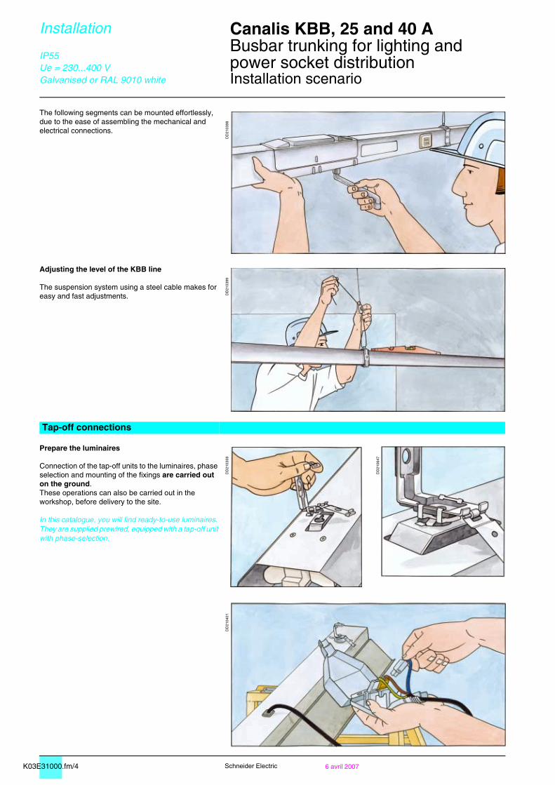
Preparation of a line segment on the floor
Assemble two or three lengths (clip together) and lock with the joint screw. D
D21
0394
DD
2103
95
Lift and position the line segment in the fixing brackets.
They are designed to immediately relieve the installer of the weight. The busbar trunking is held in place as soon as the KBB lengths are positioned in the brackets.
The brackets lock when clipped closed.
To unlock the brackets, use 3 mm flat screwdriver.
DD
2103
96D
D21
0397
DD
2106
51
K03E31000.fm/4 6 avril 2007Schneider Electric
Installation Canalis KBB, 25 and 40 A 0
Busbar trunking for lighting andpower socket distributionInstallation scenario
IP55Ue = 230...400 VGalvanised or RAL 9010 white
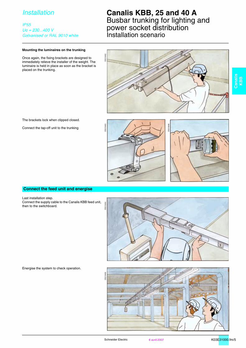
The following segments can be mounted effortlessly, due to the ease of assembling the mechanical and electrical connections.
DD
2103
98
Adjusting the level of the KBB line
The suspension system using a steel cable makes for easy and fast adjustments. D
D21
0399
Tap-off connections
Prepare the luminaires
Connection of the tap-off units to the luminaires, phase selection and mounting of the fixings are carried out on the ground. These operations can also be carried out in the workshop, before delivery to the site.
In this catalogue, you will find ready-to-use luminaires. They are supplied prewired, equipped with a tap-off unit with phase-selection.
DD
2103
59
DD
2106
47
DD
2104
01
K03E31000.fm/56 avril 2007
Can
alis
KB
B
Schneider Electric
Installation Canalis KBB, 25 and 40 A 0
Busbar trunking for lighting andpower socket distributionInstallation scenario
IP55Ue = 230...400 VGalvanised or RAL 9010 white
Mounting the luminaires on the trunking
Once again, the fixing brackets are designed to immediately relieve the installer of the weight. The luminaire is held in place as soon as the bracket is placed on the trunking.
DD
2104
02
The brackets lock when clipped closed.
Connect the tap-off unit to the trunking
DD
2104
03
DD
2106
48
Connect the feed unit and energise
Last installation step.Connect the supply cable to the Canalis KBB feed unit, then to the switchboard.
DD
2104
04
Energise the system to check operation.
DD
2104
05
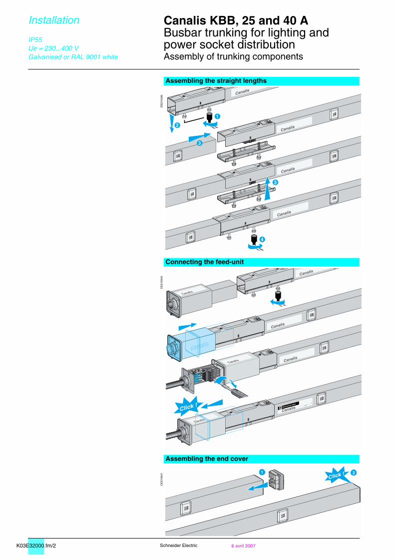
K03E32000.fm/2 6 avril 2007Schneider Electric
Installation Canalis KBB, 25 and 40 A 0
Busbar trunking for lighting andpower socket distributionAssembly of trunking components
IP55Ue = 230...400 VGalvanised or RAL 9001 white
Assembling the straight lengths
DD
2104
06
Connecting the feed-unit
DD
2105
40
Assembling the end cover
DD
2105
41
Canalis
Canalis
Canalis
Canalis
1
2
3
4
3
Canalis
Canalis
Canalis
CanalisCanalis
Telemecanique
Canalis
Canalis
Click !
Click !1 2
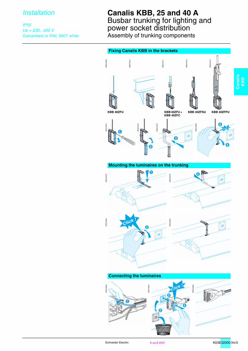
K03E32000.fm/36 avril 2007
Can
alis
KB
B
Schneider Electric
Installation Canalis KBB, 25 and 40 A 0
Busbar trunking for lighting andpower socket distributionAssembly of trunking components
IP55Ue = 230...400 VGalvanised or RAL 9001 white
Fixing Canalis KBB in the brackets
DD
2104
09
DD
2104
10
DD
2104
11
DD
2104
12
DD
2104
13
KBB 40ZFU KBB 40ZFU + KBB 40ZFC
KBB 40ZFSU KBB 40ZFPU
DD
2104
14
DD
2104
15
DD
2104
16
DD
2105
42
Mounting the luminaires on the trunking
DD
2104
18
DD
2104
19
DD
2105
43
DD
2104
21
Connecting the luminaires
DD
2104
22
DD
2105
44
DD
2104
24
1
2
Click !
4
5
1
3Click !
1
2
3
4
Click !