Contents Breakdown... · 2020-02-20 · 4 A40014-001 Bracket 5 16-1150-01 Adapter for 230 volt...
11
CU0415, CU0715 and CU0920 Service Parts September 2013 Page 1 Contents Cabinet - CU0415 or CU0715 ................................................................................................................2 Cabinet - CU0920 ................................................................................................................................... 3 Under Bin Parts ...................................................................................................................................... 4 Bin and Insulation ................................................................................................................................... 5 Refrigeration System - CU0415 and CU0715 ........................................................................................6 Refrigeration System - CU0920 .............................................................................................................7 Water System ......................................................................................................................................... 8 Controls and Electrical............................................................................................................................9 Wiring Diagram ...................................................................................................................................... 10 Schematic Diagram ...............................................................................................................................11 This is the illustrated parts list for the CU0415, CU0715 and CU0920. The CUR0415, CUR0715 and CUR0920 are -32 (208-230/60/1) versions of the matching models. There are 3 voltages, 115/60/1, 208-230/60/1 and 230/50/1. Be sure of the voltage before selecting a part.
Transcript of Contents Breakdown... · 2020-02-20 · 4 A40014-001 Bracket 5 16-1150-01 Adapter for 230 volt...

CU0415, CU0715 and CU0920 Service Parts
September 2013Page 1
ContentsCabinet - CU0415 or CU0715 ................................................................................................................2
Cabinet - CU0920 ...................................................................................................................................3
Under Bin Parts ......................................................................................................................................4
Bin and Insulation ...................................................................................................................................5
Refrigeration System - CU0415 and CU0715 ........................................................................................6
Refrigeration System - CU0920 .............................................................................................................7
Water System .........................................................................................................................................8
Controls and Electrical............................................................................................................................9
Wiring Diagram ......................................................................................................................................10
Schematic Diagram ...............................................................................................................................11
This is the illustrated parts list for the CU0415, CU0715 and CU0920. The CUR0415, CUR0715 and CUR0920 are -32 (208-230/60/1) versions of the matching models.There are 3 voltages, 115/60/1, 208-230/60/1 and 230/50/1. Be sure of the voltage before selecting a part.

CU0415, CU0715 and CU0920 Service Parts
September 2013Page 2
Cabinet - CU0415 or CU0715
Item PartNumber Number Description 1 A39993-001 Top panel, 15 inch 2 02-4677-01 Insulation, 15 inch 3 02-4694-01 Inner top panel, 15 inch 4 02-4691-01 Top frame, 15 inch 4a 03-3836-04 Screw 5 02-4685-01 Door, outer, 15 inch 6 03-3941-01 Bushing 03-3940-01 Bumper (in door slot & base) 7 03-3870-01 Screw 8 02-4685-04 Door liner, 15 inch 9 A39990-001 Left side panel 10 A39996-001 Back panel, 15 inch 11 A39990-002 Right side panel 12 02-4683-01 Front panel, 15 inch 13 03-1404-12 Screw 14 03-3943-01 Screw
Not illustrated 15 KLP7 Leg kit 16 02-4391-03 Scoop 17 A40085-001 Bin thermostat tube, 15 inch
1
2
34
5
96
10
8
7
11
12
13
14
4a

CU0415, CU0715 and CU0920 Service Parts
September 2013Page 3
Cabinet - CU0920
Item PartNumber Number Description 1 A39993-002 Top panel, 20 inch 2 02-4677-02 Insulation, 20 inch 3 02-4695-01 Inner top panel, 20 inch 4 02-4692-01 Top frame, 20 inch 4a 03-3836-04 Screw 5 02-4686-01 Door, outer, 20 inch 6 03-3941-01 Bushing 03-3940-01 Bumper (in door slot & base) 7 03-3870-01 Screw 8 02-4686-04 Door liner, 20 inch 02-4805-01 Rod, door support 9 A39990-001 Left side panel 10 A39997-001 Back panel, 20 inch 11 A39990-002 Right side panel 12 02-4684-01 Front panel, 20 inch 13 03-1404-12 Screw 14 03-3943-01 Screw
Not illustrated 15 KLP7 Leg kit 16 02-4391-03 Scoop 17 A40085-002 Bin thermostat tube, 20 inch
1
2
34
5
96
10
8
7
11
12
13
14
4a

CU0415, CU0715 and CU0920 Service Parts
Jan 2017Page 4
1
3
45
6
87
1015
1114
18
13169
17
19
12
Item PartNumber Number Description 1 A39991-001 Chassis cover, 15 inch A39991-002 Chassis cover, 20 inch 2 13-0674-01 1/4 ID Hose, requires < 24” 2a 13-0895-01 1/4 OD Hose, requires < 12” 2b 03-3961-01 Hose Clamp 3 12-3055-01 Inlet water sol valve, 115 volt 12-3055-02 Inlet water sol valve, 230 volt 4 A40014-001 Bracket 5 16-1150-01 Adapter for 230 volt models 6 A39992-002 Drain hose 7 16-0835-01 Hosefitting,230voltmodels 8 03-0571-00 Screwfordrainfitting 9 02-3692-23 Drainfittingkit 10 16-1081-01 Elbow, 230 volt models 11 03-3943-02 Screw 12 A39556-001 Fan motor bracket
13 02-4197-01 Fan blade 14 A39460-001 Fan shroud 15 Fan motor see tablePart number Model Size Voltage12-3024-01 40 11512-3024-01 70 11512-2989-01 90 11512-3024-03 40 23012-3024-03 70 23012-2989-02 90 230
16 A40077-001 Cover 17 A39994-001 Base, 15 inch A39995-001 Base, 20 inch 18 03-3940-01 Bumper 19 03-1531-08 Screw
Under Bin Parts
2
2b
2a
CU0415, CU0715 and CU0920 Service Parts
September 2013Page 5
Item PartNumber Number Description 1 02-4717-01 Right side insulation 2 02-4705-01 Bin liner, 15 inch 02-4706-01 Bin liner, 20 inch 3 02-4696-01 Insulation, 15 inch bin 02-4697-01 Insulation, 20 inch bin 4 02-4717-02 Left side insulation 5 02-4718-01 Insulationfiller
1
2
3
4
5
Bin and Insulation

CU0415, CU0715 and CU0920 Service Parts
November 2015Page 6
1
2
3
4
5
10
6
7
8
9
Item PartNumber Number Description 1 A40204-021 Evaporator 2 11-0562-01 Hot gas valve, 115 volt 11-0562-02 Hot gas valve, 230 volt 3 11-0566-03 Fan motor pressure switch 4 18-8940-01 Condenser
5 A40009-001 Suction assy, 40 lb, 230 volt A40010-001 Suction assy, 40 lb 115 volt A40010-001 Suction assy, 70 lb 6 03-3821-01 Clip 7 03-1407-08 Washer 8 18-8964-01 Grommet 9 02-4416-01 Dryer 10 03-1711-01 Thermistor clip
11 Compressors and starting componentsModel Voltage Compressor Relay Terminal Adaptor Start Capacitor OverloadCU0415-1 115/60/1 18-8962-21 18-8962-61 12-3008-01 18-8962-62 18-8962-63CU0415-32 or -6 230/60-50 18-8962-22 18-8962-51 12-3008-01 18-8962-52 18-8962-53CU0715-1 115/60/1 18-8956-21 18-8956-51 12-3008-01 18-8956-52 18-8956-53CU0715-32 or -6 230/60-50 18-8960-22 18-8960-51 12-3008-01 18-8960-52 18-8960-53
Refrigeration System - CU0415 and CU0715
10
Compressors include starting components and a dryer.
Terminal Adaptor

CU0415, CU0715 and CU0920 Service Parts
November 2015Page 7
Refrigeration System - CU0920
Item PartNumber Number Description 1 A40204-021 Evaporator 2 11-0562-01 Hot gas valve, 115 volt 11-0562-02 Hot gas valve, 230 volt 3 11-0566-03 Fan motor pressure switch 4 18-8940-01 Condenser
5 A40011-001 Suction assy, 90 lb 6 03-3821-01 Clip 7 03-1407-08 Washer 8 18-8964-01 Grommet 9 02-4416-01 Dryer 10 03-1711-01 Thermistor clip 12 12-3008-01 Terminal Adaptor
11 Compressors and starting componentsModel Voltage Compressor Relay Terminal Adaptor Start Capacitor OverloadCU0920-1 115/60 18-8959-21 18-8959-51 12-3008-01 18-8959-52 18-8959-53CU0920-32 230/60 18-8959-22 18-8959-54 12-3008-01 18-8959-55 18-8959-56CU0920-6 230/50 18-8957-26 18-8957-51 12-3008-01 18-8957-52 18-8957-53
5
10
6
8
7
12
1
2
3
4
9
10
Compressors include starting components and a dryer.

CU0415, CU0715 and CU0920 Service Parts
Page 8
1
2
4
56
8 7
9
21
20
19
18
17
1516
20
22
23
10 1112 13 14
3
Item PartNumber Number Description
1 02-4688-01 Evaporator cover2 02-4707-01 Curtain3 03-3836-04 Screw4 02-4704-01 Grommet5 02-4679-01 Evap frame6 02-4678-01 Pump hose, 60 Hz models
02-4739-01 Pump hose, 50 Hz models7 12-2986-21 Water pump, 115 volt models
12-2986-22 Water pump, 230 volt models8 11-0606-01 Thermistor, long/blue wire to
pump hose
9 02-4703-01 Pump bracket10 02-4699-01 Support
11 13-0840-01 Drain plug12 02-4702-01 Pump cover13 02-4690-01 Insulation14 A40003-001 Motor barrier15 03-3870-01 Screw16 02-4904-01 Clip17 02-4680-01 Water header top18 02-4693-01 Gasket19 02-4681-01 Water header pan20 A40012-001 Water header clip21 02-4689-01 Cubedeflector22 13-0674-07 Hose, 11.25” req.23 02-4687-01 Insulation
Water System
May 2017

CU0415, CU0715 and CU0920 Service Parts
September 2013Page 9
Item PartNumber Number Description 1 12-3062-01 Master switch 2 11-0617-21 Bin thermostat 3 12-2924-01 Transformer 115 to 12 12-2924-03 Transformer 230 to 12 4 11-0599-21 Controller 5 12-2687-01 Fuse block, 50 Hz only 6 12-2686-01 Fuse, 50 Hz onlyNot shown 7 12-3056-01 Wireharness,fitsall 8 12-1638-14 Power cord, 115 volt models 12-1638-22 Power cord, 230 volt, 50 Hz 12-1638-23 Power cord, 230 volt, 60 Hz
Controls and Electrical
12
5
6
4
3
March 2014
mtittelbach
Sticky Note
Overlay 17-3386-41 60 hz 14-3386-01 50hz

CU0415, CU0715 and CU0920 Service Parts
September 2013Page 10
REV. A FUSE (3A) (50Hz only)
Y
R
W
W
W
BU
GN/Y
BKorBL
Y
BU/W
B/W
B/W
WorBN
B/W
B/W
W
V
O
FREEZE NO
ACPWRCOM
GN/Y
POWER IN
CONTROL
BINLEVEL
SOLENOID
HOT GAS
FANMOTOR
SOLENOID
WATER
PUMPMOTOR
13
SM
2
OVERLOAD
RELAY - CURRENT
COMPRESSOR
EARTHGROUND
OFF
WATERTEMPSENSOR
ELECTRONIC CONTROL
34
LINE
LOAD
TRANSFORMER
ON
WASH3-WAYSWITCH
FAN CONTROL
BN/W
W
6
5 2
3
4 1
PUMPCOM
HARV NC
PUMP NC
BU
R
21
EVAPORATOR TEMP SENSOR
12V
12V
GND
THIS UNIT MUSTBE GROUNDED
17-3439-01
* SEE NAMEPLATE FOR PROPER VOLTAGE REQUIREMENTS AND MAXIMUM FUSE SIZE
CAUTION: MORE THAN ONE DISCONNECT MEANS MAY BE REQUIRED TO DISCONNECT ALL POWER TO UNIT
Wiring Diagram
CU0415, CU0715 and CU0920 Service Parts
September 2013Page 11
DOUBLE POLE3 WAY SWITCH(CENTER OFF)
FANCONTROL
ONWASH
BIN STAT
ELECTRONIC CONTROL
EVAPORATOR TEMP SENSOR
FANMOTOR
HOT GASSOLENOID
TRANSFORMER
12V
LINE
N or L2L1
WATERSOLENOID
WATERPUMP
COMPRESSOR
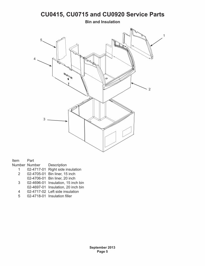
SWITCHES ON THIS UNITSHOWN IN FREEZE CYCLE
EARTHGROUND
WASH ON
PUMPCOM
A/C PWR(COM)
NC =HARVEST
WATER TEMPSENSOR
FREEZE NO
PUMP NC
32
1
5
64
Schematic Diagram