
Contents 9 – OsiSense XCC Opto-electronic rotary encodersOsiSense® XCC Opto-electronic rotary...
40
1 2 3 4 5 6 8 9 10 7 9/1 9 – OsiSense ® XCC Opto-electronic rotary encoders Selection Guide . . . . . . . . . . . . . . . . . . . . . . . . . . . . . . . . . . . . . . . . . . . . . . . . . 9/2 b Overview . . . . . . . . . . . . . . . . . . . . . . . . . . . . . . . . . . . . . . . . . . . . . . . . . . . . . 9/4 Incremental encoders b Ø 40 mm encoders, Type XCC 14 . . . . . . . . . . . . . . . . . . . . . . . . . . . . . . . . . 9/10 b Ø 58 mm encoders, Type XCC 15 . . . . . . . . . . . . . . . . . . . . . . . . . . . . . . . . . 9/12 b Ø 58 mm encoders, parameterable versions, Type XCC 15 . . . . . . . . . . . . . 9/15 b Ø 90 mm encoders, Type XCC 19 . . . . . . . . . . . . . . . . . . . . . . . . . . . . . . . . . 9/16 Single turn absolute encoders b Ø 58 mm encoders, Type XCC 25 . . . . . . . . . . . . . . . . . . . . . . . . . . . . . . . . . 9/20 b Ø 90 mm encoders, Type XCC 29 . . . . . . . . . . . . . . . . . . . . . . . . . . . . . . . . . 9/22 Multi-turn absolute encoders b Ø 58 mm encoders, Type XCC 35 . . . . . . . . . . . . . . . . . . . . . . . . . . . . . . . . . 9/26 b Ø 90 mm encoders, Type XCC 39 . . . . . . . . . . . . . . . . . . . . . . . . . . . . . . . . . 9/28 b Connection accessories . . . . . . . . . . . . . . . . . . . . . . . . . . . . . . . . . . . . . . . . . . 9/32 Rotary encoders b Connection accessories . . . . . . . . . . . . . . . . . . . . . . . . . . . . . . . . . . . . . . . . . . 9/33 b Mounting and installing accessories . . . . . . . . . . . . . . . . . . . . . . . . . . . . . . . . 9/34 Contents Courtesy of Steven Engineering, Inc.-230 Ryan Way, South San Francisco, CA 94080-6370-Main Office: (650) 588-9200-Outside Local Area: (800) 258-9200-www.stevenengineering.com
Transcript of Contents 9 – OsiSense XCC Opto-electronic rotary encodersOsiSense® XCC Opto-electronic rotary...

1
2
3
4
5
6
8
9
10
7
9/1
9 – OsiSense® XCCOpto-electronic rotary encoders
Selection Guide . . . . . . . . . . . . . . . . . . . . . . . . . . . . . . . . . . . . . . . . . . . . . . . . . 9/2
b Overview . . . . . . . . . . . . . . . . . . . . . . . . . . . . . . . . . . . . . . . . . . . . . . . . . . . . . 9/4
Incremental encodersb Ø 40 mm encoders, Type XCC 14 . . . . . . . . . . . . . . . . . . . . . . . . . . . . . . . . . 9/10
b Ø 58 mm encoders, Type XCC 15 . . . . . . . . . . . . . . . . . . . . . . . . . . . . . . . . . 9/12
b Ø 58 mm encoders, parameterable versions, Type XCC 15 . . . . . . . . . . . . . 9/15
b Ø 90 mm encoders, Type XCC 19 . . . . . . . . . . . . . . . . . . . . . . . . . . . . . . . . . 9/16
Single turn absolute encodersb Ø 58 mm encoders, Type XCC 25 . . . . . . . . . . . . . . . . . . . . . . . . . . . . . . . . . 9/20
b Ø 90 mm encoders, Type XCC 29 . . . . . . . . . . . . . . . . . . . . . . . . . . . . . . . . . 9/22
Multi-turn absolute encodersb Ø 58 mm encoders, Type XCC 35 . . . . . . . . . . . . . . . . . . . . . . . . . . . . . . . . . 9/26
b Ø 90 mm encoders, Type XCC 39 . . . . . . . . . . . . . . . . . . . . . . . . . . . . . . . . . 9/28
b Connection accessories . . . . . . . . . . . . . . . . . . . . . . . . . . . . . . . . . . . . . . . . . . 9/32
Rotary encodersb Connection accessories . . . . . . . . . . . . . . . . . . . . . . . . . . . . . . . . . . . . . . . . . . 9/33
b Mounting and installing accessories . . . . . . . . . . . . . . . . . . . . . . . . . . . . . . . . 9/34
Contents
Courtesy of Steven Engineering, Inc.-230 Ryan Way, South San Francisco, CA 94080-6370-Main Office: (650) 588-9200-Outside Local Area: (800) 258-9200-www.stevenengineering.com

1
2
3
4
5
6
7
8
9|
10
9/2
OsiSense® XCC Opto-electronic rotary encoders
Encoder type Incremental encoders
Applications Counting indication
Diameter of housing Ø 40 mm Ø 58 mm Ø 58 mm parameterable (multi-resolution) (1)
Ø 90 mm
Shaft Solid Ø 6 mm Ø 6 mm and Ø 10 mm Ø 10 mm Ø 12 mmThrough Ø 6 mm Ø 14 mm Ø 14 mm Ø 30 mm
Ø 6, 8, 10 and 12 mm (with reduction collar)
Ø 6, 8, 10 and 12 mm (with reduction collar)
Ø 12, 20 and 25 mm (with reduction collar)
Resolution Incremental encoders
100 points 100 points 100 points – 100 points256 points – – 256 to 4096 points –360 points 360 points 360 points 360 to 5760 points 360 points500 points 500 points 500 points 500 to 8000 points 500 points1000 points 1000 points 1000 points – 1000 points1024 points 1024 points 1024 points 1024 to 16,384 points 1024 points2500 points – 2500 points – 2500 points3600 points – – – 3600 points4096 points – – – –5000 points – 5000 points 5000 to 80,000 points 5000 points10,000 points – – – 10,000 points
Absolute encoders
4096 points/8192 turns (12-bit/13-bit)
– – – –
8192 points – – – –8192 points/4096 turns (13-bit/12-bit)
– – – –
Output stage/supply (2)
Incremental encoders
Type R (N) 5 V, RS 422, 4.5 to 5.5 V
– – 5 V, RS 422, 4.5 to 5.5 V
Type K (N) Push-pull, 11 to 30 V – – Push-pull, 11 to 30 VType X – 5 V, RS 422, 4.75 to 30 V 5 V, RS 422, 4.75 to 30 V –Type Y – Push-pull, 5 to 30 V Push-pull, 5 to 30 V –
Absolute encoders
Type KB (N) or KG (N) – – – –
Type SB (N) or SG (N) – – – –
Type C – – – –Type F – – – –
Connection Pre-cabled, radial p – – –Connector, radial, M23 – p p p
Terminal block, radial – – – –
Catalog Numbers XCC14ppppp XCC15ppppp XCC15ppppMppp XCC19ppppp
Pages 9/10 9/12 to 9/17 9/21
(1) Parameterable version: multiplication of the basic resolution of the disc using dip switches, the factory setting being that of the lowest value.(2) Characteristics of the output stage/supply types:
- Type R (N): 5 V output driver, RS 422, 4.5 to 5,5 V.- Type K (N): push-pull output driver, 11 to 30 V.- Type X: 5 V output driver, RS 422, 4.75 to 30 V.- Type Y: push-pull output driver, 5 to 30 V.- KB (N) or KG (N) output: push-pull output driver, 11 to 30 V, binary code KB (N) or Gray code KG (N).
Selection Guide
Courtesy of Steven Engineering, Inc.-230 Ryan Way, South San Francisco, CA 94080-6370-Main Office: (650) 588-9200-Outside Local Area: (800) 258-9200-www.stevenengineering.com
1
2
3
4
5
6
7
8
9
10
9/3
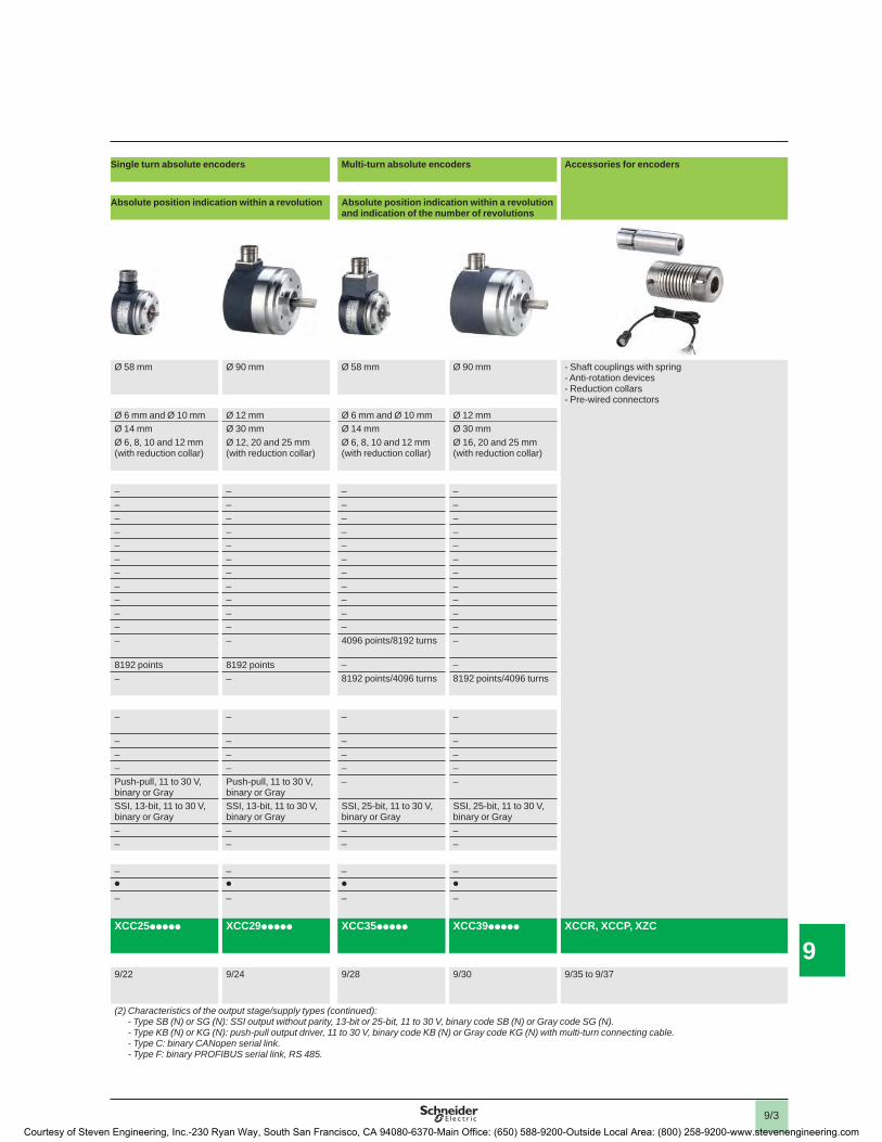
Single turn absolute encoders Multi-turn absolute encoders Accessories for encoders
Absolute position indication within a revolution Absolute position indication within a revolution and indication of the number of revolutions
Ø 58 mm Ø 90 mm Ø 58 mm Ø 90 mm - Shaft couplings with spring- Anti-rotation devices- Reduction collars- Pre-wired connectors
Ø 6 mm and Ø 10 mm Ø 12 mm Ø 6 mm and Ø 10 mm Ø 12 mmØ 14 mm Ø 30 mm Ø 14 mm Ø 30 mmØ 6, 8, 10 and 12 mm (with reduction collar)
Ø 12, 20 and 25 mm (with reduction collar)
Ø 6, 8, 10 and 12 mm (with reduction collar)
Ø 16, 20 and 25 mm (with reduction collar)
– – – –– – – –– – – –– – – –– – – –– – – –– – – –– – – –– – – –– – – –– – – –– – 4096 points/8192 turns –
8192 points 8192 points – –– – 8192 points/4096 turns 8192 points/4096 turns
– – – –
– – – –– – – –– – – –Push-pull, 11 to 30 V, binary or Gray
Push-pull, 11 to 30 V, binary or Gray
– –
SSI, 13-bit, 11 to 30 V, binary or Gray
SSI, 13-bit, 11 to 30 V, binary or Gray
SSI, 25-bit, 11 to 30 V, binary or Gray
SSI, 25-bit, 11 to 30 V, binary or Gray
– – – –– – – –
– – – –p p p p
– – – –
XCC25ppppp XCC29ppppp XCC35ppppp XCC39ppppp XCCR, XCCP, XZC
9/22 9/24 9/28 9/30 9/35 to 9/37
(2) Characteristics of the output stage/supply types (continued):- Type SB (N) or SG (N): SSI output without parity, 13-bit or 25-bit, 11 to 30 V, binary code SB (N) or Gray code SG (N).- Type KB (N) or KG (N): push-pull output driver, 11 to 30 V, binary code KB (N) or Gray code KG (N) with multi-turn connecting cable.- Type C: binary CANopen serial link.- Type F: binary PROFIBUS serial link, RS 485.
Courtesy of Steven Engineering, Inc.-230 Ryan Way, South San Francisco, CA 94080-6370-Main Office: (650) 588-9200-Outside Local Area: (800) 258-9200-www.stevenengineering.com

1
2
3
4
5
6
7
8
9|
10
9/4
OsiSense® XCC Opto-electronic rotary encoders
Applications The increase in the power of processing systems, coupled with the requirements for high productivity, has created the need for continuous information in all areas of production regarding:b Counting, positioning by counting,b Absolute positioning,b Speed control.
ExampleThe positioning of a moving part is fully controlled by the processing system via the encoder.
b Processing units:please refer to our “Premium automation platform” catalog.
b Variable speed drives:please refer to our “Variable speed drives and starters” catalog.
Principle of the opto-electronic rotary encoder
The opto-electronic rotary encoder is an angular position sensor.
Mechanically coupled to a driving spindle of a machine, the shaft of the encoder rotates a disc that comprises a succession of opaque and transparent sectors.
Light from light emitting diodes (LEDs) passes through the transparent sectors of the disc as they appear and is detected by photosensitive diodes.
The photosensitive diodes, in turn, generate an electrical signal which is amplifi ed and converted into a digital signal before being transmitted to a processing system or an electronic variable speed drive.
The electrical output of the encoder therefore represents, in digital form, the angular position of the input shaft.
Types of opto-electronic rotary encoder
b Incremental encoders:- Counting, positioning by counting, speed.
b Parameterable incremental encoders:- Multiplication of the basic resolution of the disc using dip switches (the factory setting being that of the lowest value).
b Single turn and multi-turn absolute encoders:- Absolute positioning.
b Fieldbus multi-turn absolute encoders:- CANopen and PROFIBUS-DP.
Variable speed drive
Programmable controller
MotorEncoder
Terminal
Overview
Courtesy of Steven Engineering, Inc.-230 Ryan Way, South San Francisco, CA 94080-6370-Main Office: (650) 588-9200-Outside Local Area: (800) 258-9200-www.stevenengineering.com
1
2
3
4
5
6
7
8
9
10
9/5
OsiSense® XCC Opto-electronic rotary encoders
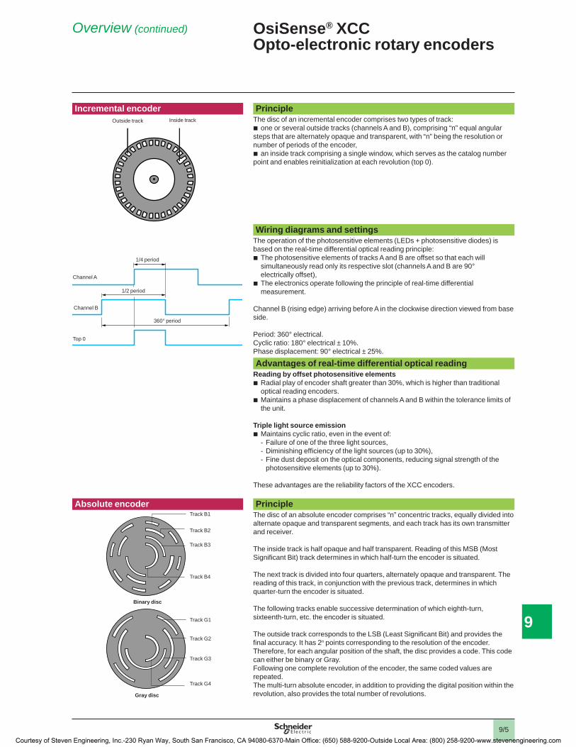
Incremental encoder PrincipleThe disc of an incremental encoder comprises two types of track:b one or several outside tracks (channels A and B), comprising “n” equal angular steps that are alternately opaque and transparent, with “n” being the resolution or number of periods of the encoder,b an inside track comprising a single window, which serves as the catalog number point and enables reinitialization at each revolution (top 0).
Wiring diagrams and settingsThe operation of the photosensitive elements (LEDs + photosensitive diodes) is based on the real-time differential optical reading principle:b The photosensitive elements of tracks A and B are offset so that each will
simultaneously read only its respective slot (channels A and B are 90° electrically offset),
b The electronics operate following the principle of real-time differential measurement.
Channel B (rising edge) arriving before A in the clockwise direction viewed from base side.
Period: 360° electrical.Cyclic ratio: 180° electrical ± 10%. Phase displacement: 90° electrical ± 25%.
Advantages of real-time differential optical readingReading by offset photosensitive elementsb Radial play of encoder shaft greater than 30%, which is higher than traditional
optical reading encoders.b Maintains a phase displacement of channels A and B within the tolerance limits of
the unit.
Triple light source emissionb Maintains cyclic ratio, even in the event of:
Failure of one of the three light sources,- Diminishing effi ciency of the light sources (up to 30%), - Fine dust deposit on the optical components, reducing signal strength of the-
photosensitive elements (up to 30%).
These advantages are the reliability factors of the XCC encoders.
Absolute encoder PrincipleThe disc of an absolute encoder comprises “n” concentric tracks, equally divided into alternate opaque and transparent segments, and each track has its own transmitter and receiver.
The inside track is half opaque and half transparent. Reading of this MSB (Most Signifi cant Bit) track determines in which half-turn the encoder is situated.
The next track is divided into four quarters, alternately opaque and transparent. The reading of this track, in conjunction with the previous track, determines in which quarter-turn the encoder is situated.
The following tracks enable successive determination of which eighth-turn, sixteenth-turn, etc. the encoder is situated.
The outside track corresponds to the LSB (Least Signifi cant Bit) and provides the fi nal accuracy. It has 2n points corresponding to the resolution of the encoder. Therefore, for each angular position of the shaft, the disc provides a code. This code can either be binary or Gray.Following one complete revolution of the encoder, the same coded values are repeated.The multi-turn absolute encoder, in addition to providing the digital position within the revolution, also provides the total number of revolutions.
Outside track Inside track
Channel A
Channel B
Top 0
360° period
1/2 period
1/4 period
Track B1
Track B2
Track B3
Track B4
Track G1
Track G2
Track G3
Track G4
Binary disc
Gray disc
Overview (continued)
Courtesy of Steven Engineering, Inc.-230 Ryan Way, South San Francisco, CA 94080-6370-Main Office: (650) 588-9200-Outside Local Area: (800) 258-9200-www.stevenengineering.com

1
2
3
4
5
6
7
8
9|
10
9/6
OsiSense® XCC Opto-electronic rotary encoders
Absolute encoder (continued) Binary codingThe binary code is directly usable by processing systems (programmable controllers for example) in order to execute calculations or comparisons, but has the disadvantage of having several bits which change state between two positions.
Gray codingThe Gray code offers the advantage of only changing one bit between two consecutive numbers.
Example of Gray code disc
Reintroduction of the fi rst twenty-four decimal values corresponding to the reading of the fi rst fi ve tracks.
Advantages of position detection by an absolute encoderAn absolute encoder continuously provides a code that is an image of the actual position of the moving object being monitored.
On power-up, or restart following a loss of powerº, the encoder provides data that is directly exploitable by the processing system.
B1
0 1 2 3 4 5 6 7 8
B2
B3
B4
G1
0 1 2 3 4 5 6 7 8 9 10 11 12 13 14 15
G2
G3
G4
0 1 2 3 4 5 6 7 8 9 10 11 12 13 14 15 16 17 18 19 20 21 22 23 24
0 0 0 0 0 0 0 0 0 0 0 0 00 0 0 0 0 0 0 0 0 0 0 0 00 0 0 0 0 0 0 0 0 0 0 00 0 0 0 0 0 0 0 00 0 0 0 0 0 0 0 0 0 0 0 0 0 0 0
1 1 1 1 1 1 1 1 1 1 1 11 1 1 1 1 1 1 1 1 1 1 1
1 1 1 1 1 1 1 1 1 1 1 1 11 1 1 1 1 1 1 1 1 1 1 1 1 1 1 1
1 1 1 1 1 1 1 1 1
20
22
24
28
216
Overview (continued)
Courtesy of Steven Engineering, Inc.-230 Ryan Way, South San Francisco, CA 94080-6370-Main Office: (650) 588-9200-Outside Local Area: (800) 258-9200-www.stevenengineering.com

1
2
3
4
5
6
7
8
9
10
9/7
7 specifi cations to be established 1 Functionb Incremental encoder
Provides counting indication.
b Single turn absolute encoderProvides absolute position within each revolution.
b Multi-turn absolute encoderProvides absolute position within each revolution and indicates total number of revolutions.
2 Diameter of housingb Incremental encoders
Ø 40, 58 and 90
b Single turn and multi-turn absolute encodersØ 58 and 90
3 Diameter of shaft b Ø 6 mm to 30 mm, depending on modelb Reduction collars
For Ø 58 and 90 mm encoders, with Ø 14, 15 and 30 mm through shaft, reduction collars are available to reduce the diameters:
- from 14 to 6, 8, 10 and 12 - from 15 to 6, 8, 10, 12 and 14 - from 30 to 12, 16, 20 and 25.
4 Type of shaftb Solid shaft
The shaft of the encoder is mechanically linked to a drive shaft using a fl exible coupling, which eliminates alignment inaccuracies.
b Through shaft/Hollow shaftThe encoder is mounted directly on the drive shaft. A fl exible mounting kit prevents encoder rotation and compensates for alignment inaccuracies.
5 Connection methodb Pre-cabled with 2 m long shielded cable or M23/M12 connector.b Radial type connection.
6 Resolution b Number of points per revolution.b Number of revolutions (for multi-turn absolute encoders).b On Ø 58 parameterable incremental encoders, this resolution can be adjusted
using dip switches (multiplication factor up to 16 times on 9 basic resolutions).
7 Type of outputb Incremental encoders
5 V output driver, RS-422, 4.75 to 30 V.Push-pull output driver, 5 to 30 V, 11...30 V.
b Single turn absolute encoders (depending on model)Push-pull output driver, 11 to 30 V, binary code or Gray code.SSI output without parity, 13-bit clock, 11 to 30 V, binary code or Gray code.
b Multi-turn absolute encoders (depending on model)SSI output without parity, 25-bit clock, 11 to 30 V, binary code or Gray code.
b Parallel outputs obtainable using converter connecting cablesThe SSI versions can be converted to a parallel version by using the deserialization connecting cable (see page 9/32 ).
500 mm
500 mm
SSI output
SSI output
// output
// outputEncoders XCC35 or 39
Encoders XCC35 or 39
Deserialization connecting cable
Cable 8 conductors
Deserialization connecting cable
Connector kitx meters
OsiSense® XCC Opto-electronic rotary encodersSpecifi cations required to defi ne an encoder
Selection of Encoder Type
Courtesy of Steven Engineering, Inc.-230 Ryan Way, South San Francisco, CA 94080-6370-Main Office: (650) 588-9200-Outside Local Area: (800) 258-9200-www.stevenengineering.com

1
2
3
4
5
6
7
8
9|
10
9/8
OsiSense® XCC Opto-electronic rotary encodersSpecifi cations required to defi ne an encoder
Installation precautions Type of cablesIn an environment subject to considerable electrical interference, it is recommended that cables with several twisted pairs, reinforced by general shielding, be used.
For the signals, it is recommended that standard 0.14 mm2/0.22 mm2 (26/24 AWG)conductors be used.
For 5 V supply encoders.Due to line voltage drops, it is recommended that the 0 V and + V supply cables have the following minimum cross-sectional areas:b 0.14 mm2 (26 AWG) if the encoder-supply distance is less than 30 m,b 0.22 mm2 (24 AWG) if the encoder-supply distance is greater than 30 m.
CablingSeparate, by as much as possible, the connecting cables to encoders and power cables. Also, avoid parallel cable runs. Maintain a distance of at least 20 cm and, in the event of cables crossing, ensure that the crossovers are at right-angles.
When using cables with twisted pairs (shielded or non-shielded), group signal cables in common pairs.
In environments subject to electrical interference, we recommend grounding the encoder base using one of the mounting screws.
Connect the control inputs to a potential (absolute encoder).Connect all 0 V connections back to a star point, i.e. only one and same referential.Ground the shielding throughout 360° using tap-off braids. This is to be done at both ends of each cable. To ground the shielding use at least 4 mm2 cable. As much as possible, ground the 0 V of the supply to the encoders on the supply side. Maximum frequency of signals for SSI depending on distance:Indicative values that can vary depending on the cable specifi cations.
Distance (m) Frequency (kHz)50 400100 300200 200400 100
SupplyIt is imperative that regulated and smoothed power supplies, with a ripple factor on 24 V of 500 mV and on 5 V of 200 mV, are used that are specifi cally for the encoder. Schneider Electric ABL7 range power supplies are available. Please refer to our “Power supplies, splitter boxes and interfaces” catalog. For 5 to 30 V encoders, the supply via a transformer with a 24 V rms rectifi ed and smoothed secondary is prohibited, since the DC voltage obtained is higher than the supply voltage limits of the encoder.Prior to power-up for the fi rst time, ensure that the rated supply voltage of the encoder is suitable for the supply.
Precautions
Courtesy of Steven Engineering, Inc.-230 Ryan Way, South San Francisco, CA 94080-6370-Main Office: (650) 588-9200-Outside Local Area: (800) 258-9200-www.stevenengineering.com

1
2
3
4
5
6
7
8
9
10
9/9
OsiSense® XCC Opto-electronic rotary encodersSpecifi cations required to defi ne an encoder, installation, power-up
Connection and power-up precautions ConnectionThe plugging-in or unplugging of a connector version encoder must only be done while the supply is disconnected.
Encoder supplied by central unit:b Disconnect supply to central unit,b Proceed with connection or disconnection,b Re-establish supply to central unit.
Encoder supplied by source external to central unit:b Disconnect supply to central unit, then disconnect supply to encoder,b Proceed with connection or disconnection,b Re-establish supply to encoder, then re-establish supply to central unit.
Power-upFor synchronization reasons, the power-up or switching-off of the encoder must coincide with that of its associated electronics.
Precautions
Courtesy of Steven Engineering, Inc.-230 Ryan Way, South San Francisco, CA 94080-6370-Main Office: (650) 588-9200-Outside Local Area: (800) 258-9200-www.stevenengineering.com

1
2
3
4
5
6
7
8
9|
10
9/10
OsiSense® XCC Incremental encodersØ 40 mm encoders
EnvironmentEncoder type XCC1406Ppppp XCC1406Tpppp
Conformity e
Temperature Operation (housing) °C (°F) - 20 to + 80 (- 4 to + 176)Storage °C (°F) - 30 to + 85 (- 22 to + 185)
Degree of protection Conforming to IEC 60529 IP 54 IP 52Vibration resistance Conforming to IEC 60068-2-6 10 gn (f = 10 to 500 Hz)Shock resistance Conforming to IEC 60068-2-27 30 gn, duration 11 msResistance to electromagnetic interference
Electrostatic discharges Conforming to IEC 61000-4-2: level 3, 8 kV air; 4 kV contactRadiated electromagnetic fi elds (electromagnetic waves)
Conforming to IEC 61000-4-3: level 3, 10 V/m
Fast transients (Start/Stop interference)
Conforming to IEC 61000-4-4: level 3, 2 kV (1 kV for inputs/outputs)
Surge withstand Conforming to IEC 61000-4-5: level 2, 1 kVMaterials Base Aluminium or Zamak
Housing Aluminium or ZamakShaft Stainless steel or AluminiumBall bearings 688AZZ1
Mechanical specifi cationsShaft type mm Ø 6, solid shaft (g7) Ø 6, through shaft (H7)Maximum rotational speed Continuous 9000 rpm Shaft moment of inertia g.cm2 10 (0.14 oz.in.) 5 (0.07 oz.in.)Torque N•cm 0.2 (0.28 oz.in.) 0.25 (0.35 oz.in.)Maximum load Radial N 20
Axial N 10
Electrical specifi cationsConnection Radial: pre-cabled, 8 x 0.14 mm2 shielded,
Ø ext = 6 mm, length = 2 mCrimped metal cable entry
Pre-cabled 8 x 0.14 mm2 shielded, Ø ext = 6 mm, length = 2 mCrimped metal cable entry
Frequency kHz 100Number of channels 3 channels: A, B, top 0 and complements
Encoders with Type R output stage: 5 V output driver, RS-422, 4.5 to 5.5 V supplySupply voltage c 5 V ± 10%
Max. ripple: 200 mVCurrent consumption, no-load mA 100 max.Output current mA 40 max.Output levels Low level (Is = 20 mA) 0.5 V max.
High level (Is = 20 mA) 2.5 V min.
Encoders with Type K output stage: push-pull output driver, 11 to 30 V supplySupply voltage c 11 V to 30 V.
Max. ripple: 500 mVCurrent consumption, no-load mA 75 max.Protection Against short-circuits and reverse polarityOutput current mA 40 max.Output levels Low level (Is = 20 mA) 1.5 V max.
High level (Is = 20 mA) V supply - 3 V min.
Wiring diagramsType R output stage Type K output stage
A,B, 0
0 V
100 RS422
0 V
A B 0
A B 0
Encoder ProcessingSupply 5 V
Ismax.
0 V0 V
A B 0
A B 0
Push-Pull
Encoder ProcessingSupply 11 V/30 V
Ismax.
Specifi cations, Wiring Diagrams
Courtesy of Steven Engineering, Inc.-230 Ryan Way, South San Francisco, CA 94080-6370-Main Office: (650) 588-9200-Outside Local Area: (800) 258-9200-www.stevenengineering.com

1
2
3
4
5
6
7
8
9
10
9/11
OsiSense® XCC Incremental encodersØ 40 mm encoders
Solid shaft, Ø 6 mmResolution Connection
methodOutput stage type (1)
Supply voltage Catalog number Weightkg (lbs)
100 points Pre-cabled, radial 2 m
5 V, RS-422 4.5 to 5.5 V XCC1406PR01R 0.355 (0.787)
Push-pull 11 to 30 V XCC1406PR01K 0.355 (0.787)
360 points Pre-cabled, radial 2 m
5 V, RS-422 4.5 to 5.5 V XCC1406PR03R 0.355 (0.787)
Push-pull 11 to 30 V XCC1406PR03K 0.355 (0.787)
500 points Pre-cabled, radial 2 m
5 V, RS-422 4.5 to 5.5 V XCC1406PR05R 0.355 (0.787)
Push-pull 11 to 30 V XCC1406PR05K 0.355 (0.787)
1000 points Pre-cabled, radial 2 m
5 V, RS-422 4.5 to 5.5 V XCC1406PR10R 0.355 (0.787)
Push-pull 11 to 30 V XCC1406PR10K 0.355 (0.787)
1024 points Pre-cabled, radial 2 m
5 V, RS-422 4.5 to 5.5 V XCC1406PR11R 0.355 (0.787)
Push-pull 11 to 30 V XCC1406PR11K 0.355 (0.787)
Through shaft, Ø 6 mm (2)Resolution Connection
methodOutput stage type (1)
Supply voltage Catalog number Weightkg (lbs)
100 points Pre-cabled, radial 2 m
5 V, RS-422 4.5 to 5.5 V XCC1406TR01R 0.405 (0.893)
Push-pull 11 to 30 V XCC1406TR01K 0.405 (0.893)
360 points Pre-cabled, radial 2 m
5 V, RS-422 4.5 to 5.5 V XCC1406TR03R 0.405 (0.893)
Push-pull 11 to 30 V XCC1406TR03K 0.405 (0.893)
500 points Pre-cabled, radial 2 m
5 V, RS-422 4.5 to 5.5 V XCC1406TR05R 0.405 (0.893)
Push-pull 11 to 30 V XCC1406TR05K 0.405 (0.893)
1000 points Pre-cabled, radial 2 m
5 V, RS-422 4.5 to 5.5 V XCC1406TR10R 0.405 (0.893)
Push-pull 11 to 30 V XCC1406TR10K 0.405 (0.893)
1024 points Pre-cabled, radial 2 m
5 V, RS-422 4.5 to 5.5 V XCC1406TR11R 0.405 (0.893)
Push-pull 11 to 30 V XCC1406TR11K 0.405 (0.893)
(1) For specifi cations of the output stage type (indicated by last letter of the catalog number), see page 9/10 .
(2) Anti-rotation device included with encoder.
Catalog Numbers
XCC1406PRppp
XCC1406TRppp
Courtesy of Steven Engineering, Inc.-230 Ryan Way, South San Francisco, CA 94080-6370-Main Office: (650) 588-9200-Outside Local Area: (800) 258-9200-www.stevenengineering.com

1
2
3
4
5
6
7
8
9|
10
9/12
OsiSense® XCC Incremental encodersØ 58 mm encoders
EnvironmentEncoder type XCC1506Ppppp XCC1510Ppppp XCC1514Tpppp
Conformity e
Temperature Operation (housing) °C (°F) - 30 to + 100 (- 22 to + 212) [except XCCTSMppX and XCCTSMppY: - 30 to + 70 (- 22 to + 158)]Storage °C (°F) - 30 to + 85 (- 22 to + 185)
Degree of protection Conforming to IEC 60529 IP 65 IP 65 (IP 67 with collar option XCCRB3)
IP 65
Vibration resistance Conforming to IEC 60068-2-6 10 gn (f = 55 to 2000 Hz)Shock resistance Conforming to IEC 60068-2-27 30 gn, duration 11 msResistance to electromagnetic interference
Electrostatic discharges Conforming to IEC 61000-4-2: level 3, 8 kV air, 4 kV contactRadiated electromagnetic fi elds (electromagnetic waves)
Conforming to IEC 61000-4-3: level 3, 10 V/m
Fast transients (Start/Stop interference)
Conforming to IEC 61000-4-4: level 3, 2 kV (1 kV for inputs/outputs)
Surge withstand Conforming to IEC 61000-4-5: level 2, 1 kVMaterials Base Aluminium
Housing ZamakShaft Stainless steelBall bearings 6000ZZ1 6803ZZ
Mechanical specifi cationsShaft type Ø 6, solid shaft (g7) Ø 10 mm, solid shaft Ø 14, through shaft (H7)Maximum rotational speed Continuous 9000 rpm 9000 rpm 6000 rpmShaft moment of inertia g.cm2 10 (0.14 oz.in.) 10 (0.14 oz.in.) 22 (0.31 oz.in.)Torque N•cm 0.4 (0.57 oz.in.) 0.4 (0.57 oz.in.) 0.6 (0.85 oz.in.)Maximum load Radial N 100 100 50
Axial N 50 50 20
Electrical specifi cationsConnection Connector M23, 12-pin male connectorFrequency kHz 300Number of channels 3 channels: A, B, top 0 and complements
Encoders with Type X output stage: 5 V output driver, RS-422, 4.75 to 30 V supplySupply voltage c 4.75 to 30 V
Max. ripple: 500 mVCurrent consumption, no-load mA 75 max.Protection Against short-circuits and reverse polarityOutput current mA 40 max.Output levels Low level (Is = 20 mA) 0.5 V max.
High level (Is = 20 mA) 4.5 V min.
Encoders with Type Y output stage: push-pull output driver, 5 to 30 V supplySupply voltage c 5 to 30 V
Max. ripple: 500 mVCurrent consumption, no-load mA 75 max.Protection Against short-circuits and reverse polarityOutput current mA 40 max.Output levels(for U supply = 30 V) (1)
Low level (Is = 20 mA) 0.5 V max.
High level (Is = 20 mA) V supply - 2.5 V min.
Wiring diagramsType X output stage Type Y output stage
(1) RS-422 compatible on 5 V supply.
A,B, 0
0 V
100 RS422
+ 5 V
0 V
A B 0
A B 0
Encoder ProcessingSupply 4.75 V/30 V
Ismax.
Supply 5 V
0 V0 V
A B 0
A B 0
Push-Pull(1)
Encoder ProcessingSupply 5 V/30 V
Ismax.
Specifi cations, Wiring Diagrams
Courtesy of Steven Engineering, Inc.-230 Ryan Way, South San Francisco, CA 94080-6370-Main Office: (650) 588-9200-Outside Local Area: (800) 258-9200-www.stevenengineering.com

1
2
3
4
5
6
7
8
9
10
9/13
OsiSense® XCC Incremental encodersØ 58 mm encoders
Solid shaft, Ø 6 mmResolution Connection
method (1)Output stage type (2)
Supply voltage
Catalog number Weightkg (lbs)
100 points Connector, radial M23 male
5 V, RS-422 4.75 to 30 V XCC1506PS01X 0.495 (1.091)
Push-pull 5 to 30 V XCC1506PS01Y 0.495 (1.091)
360 points Connector, radial M23 male
5 V, RS-422 4.75 to 30 V XCC1506PS03X 0.495 (1.091)
Push-pull 5 to 30 V XCC1506PS03Y 0.495 (1.091)
500 points Connector, radial M23 male
5 V, RS-422 4.75 to 30 V XCC1506PS05X 0.495 (1.091)
Push-pull 5 to 30 V XCC1506PS05Y 0.495 (1.091)
1000 points Connector, radial M23 male
5 V, RS-422 4.75 to 30 V XCC1506PS10X 0.495 (1.091)
Push-pull 5 to 30 V XCC1506PS10Y 0.495 (1.091)
1024 points Connector, radial M23 male
5 V, RS-422 4.75 to 30 V XCC1506PS11X 0.495 (1.091)
Push-pull 5 to 30 V XCC1506PS11Y 0.495 (1.091)
2500 points Connector, radial M23 male
5 V, RS-422 4.75 to 30 V XCC1506PS25X 0.495 (1.091)
Push-pull 5 to 30 V XCC1506PS25Y 0.495 (1.091)
5000 points Connector, radial M23 male
5 V, RS-422 4.75 to 30 V XCC1506PS50X 0.495 (1.091)
Push-pull 5 to 30 V XCC1506PS50Y 0.495 (1.091)
Solid shaft, Ø 10 mmResolution Connection
method (1)Output stage type (2)
Supply voltage
Catalog number Weightkg (lbs)
100 points Connector, radialM23 male
5 V, RS-422 4.75 to 30 V XCC1510PS01X 0.465 (1.025)
Push-pull 5 to 30 V XCC1510PS01Y 0.465 (1.025)
360 points Connector, radial M23 male
5 V, RS-422 4.75 to 30 V XCC1510PS03X 0.465 (1.025)
Push-pull 5 to 30 V XCC1510PS03Y 0.465 (1.025)
500 points Connector, radial M23 male
5 V, RS-422 4.75 to 30 V XCC1510PS05X 0.465 (1.025)
Push-pull 5 to 30 V XCC1510PS05Y 0.465 (1.025)
1000 points Connector, radial M23 male
5 V, RS-422 4.75 to 30 V XCC1510PS10X 0.465 (1.025)
Push-pull 5 to 30 V XCC1510PS10Y 0.465 (1.025)
1024 points Connector, radial M23 male
5 V, RS-422 4.75 to 30 V XCC1510PS11X 0.465 (1.025)
Push-pull 5 to 30 V XCC1510PS11Y 0.465 (1.025)
2500 points Connector, radial M23 male
5 V, RS-422 4.75 to 30 V XCC1510PS25X 0.465 (1.025)
Push-pull 5 to 30 V XCC1510PS25Y 0.465 (1.025)
5000 points Connector, radial M23 male
5 V, RS-422 4.75 to 30 V XCC1510PS50X 0.465 (1.025)
Push-pull 5 to 30 V XCC1510PS50Y 0.465 (1.025)
(1) For female connector use XZC C23FDP120S or pre-wired connectors (2, 5 or 10 m), see page 9/33 .
(2) For specifi cations of the output stage type (indicated by last letter of the catalog number), see page 9/12 .
Catalog Numbers
XCC1506PSppp
XCC1510PSppp
Courtesy of Steven Engineering, Inc.-230 Ryan Way, South San Francisco, CA 94080-6370-Main Office: (650) 588-9200-Outside Local Area: (800) 258-9200-www.stevenengineering.com

1
2
3
4
5
6
7
8
9|
10
9/14
OsiSense® XCC Incremental encodersØ 58 mm encoders
Through shaft, Ø 14 mm (1)Resolution Connection
method (2)Output stage type (3)
Supply voltage
Catalog number Weightkg (lbs)
100 points Connector, radial M23 male
5 V, RS-422 4.75 to 30 V XCC1514TS01X 0.435 (0.959)
Push-pull 5 to 30 V XCC1514TS01Y 0.435 (0.959)
360 points Connector, radial M23 male
5 V, RS-422 4.75 to 30 V XCC1514TS03X 0.435 (0.959)
Push-pull 5 to 30 V XCC1514TS03Y 0.435 (0.959)
500 points Connector, radial M23 male
5 V, RS-422 4.75 to 30 V XCC1514TS05X 0.435 (0.959)
Push-pull 5 to 30 V XCC1514TS05Y 0.435 (0.959)
1000 points Connector, radial M23 male
5 V, RS-422 4.75 to 30 V XCC1514TS10X 0.435 (0.959)
Push-pull 5 to 30 V XCC1514TS10Y 0.435 (0.959)
1024 points Connector, radial M23 male
5 V, RS-422 4.75 to 30 V XCC1514TS11X 0.435 (0.959)
Push-pull 5 to 30 V XCC1514TS11Y 0.435 (0.959)
2500 points Connector, radial M23 male
5 V, RS-422 4.75 to 30 V XCC1514TS25X 0.435 (0.959)
Push-pull 5 to 30 V XCC1514TS25Y 0.435 (0.959)
5000 points Connector, radial M23 male
5 V, RS-422 4.75 to 30 V XCC1514TS50X 0.435 (0.959)
Push-pull 5 to 30 V XCC1514TS50Y 0.435 (0.959)
Through shaft, Ø 6, 8, 10 and 12 mm (1)Encoder type Diameter
mm
Reduction collar to be ordered (see page 9/35 )
Encoders with through shaft XCC1514TSppp
Ø 6 XCCR158RDA06
Ø 8 XCCR158RDA08
Ø 10 XCCR158RDA10
Ø 12 XCCR158RDA12
(1) Anti-rotation device included with encoder.(2) For female connector use XZC C23FDP120S or pre-wired connectors (2, 5 or 10 m), see
page 9/33 .(3) For specifi cations of the output stage type (indicated by last letter of the catalog number), see
page 9/12 .
Catalog Numbers (continued)
XCC1514TSppp
XCCR158RDApp
Courtesy of Steven Engineering, Inc.-230 Ryan Way, South San Francisco, CA 94080-6370-Main Office: (650) 588-9200-Outside Local Area: (800) 258-9200-www.stevenengineering.com

1
2
3
4
5
6
7
8
9
10
9/15
OsiSense® XCC Incremental encodersØ 58 mm encodersParameterable versions (1)
Parameterable with solid shaft, Ø 10 mmResolution Connection
method (2)Output stage type (3)
Supply voltage
Catalog number Weightkg (lbs)
256 to 4096 points
Connector, radial M23male
5 V, RS-422 4.75 to 30 V XCC1510PSM02X 0.465 (1.025)
Push-pull 5 to 30 V XCC1510PSM02Y 0.465 (1.025)
360 to 5760 points
Connector, radial M23male
5 V, RS-422 4.75 to 30 V XCC1510PSM03X 0.465 (1.025)
Push-pull 5 to 30 V XCC1510PSM03Y 0.465 (1.025)
500 to 8000 points
Connector, radial M23male
5 V, RS-422 4.75 to 30 V XCC1510PSM05X 0.465 (1.025)
Push-pull 5 to 30 V XCC1510PSM05Y 0.465 (1.025)
1024 to 16,384 points
Connector, radial M23male
5 V, RS-422 4.75 to 30 V XCC1510PSM11X 0.465 (1.025)
Push-pull 5 to 30 V XCC1510PSM11Y 0.465 (1.025)
5000 to 80,000 points
Connector, radial M23male
5 V, RS-422 4.75 to 30 V XCC1510PSM50X 0.465 (1.025)
Push-pull 5 to 30 V XCC1510PSM50Y 0.465 (1.025)
Parameterable with through shaft, Ø 14 mm (4)Resolution Connection
method (2)Output stage type (3)
Supply voltage
Catalog number Weightkg (lbs)
256 to 4096 points
Connector, radial M23male
5 V, RS-422 4.75 to 30 V XCC1514TSM02X 0.435 (0.959)
Push-pull 5 to 30 V XCC1514TSM02Y 0.435 (0.959)
360 to 5760 points
Connector, radial M23male
5 V, RS-422 4.75 to 30 V XCC1514TSM03X 0.435 (0.959)
Push-pull 5 to 30 V XCC1514TSM03Y 0.435 (0.959)
500 to 8000 points
Connector, radial M23male
5 V, RS-422 4.75 to 30 V XCC1514TSM05X 0.435 (0.959)
Push-pull 5 to 30 V XCC1514TSM05Y 0.435 (0.959)
1024 to 16,384 points
Connector, radial M23male
5 V, RS-422 4.75 to 30 V XCC1514TSM11X 0.435 (0.959)
Push-pull 5 to 30 V XCC1514TSM11Y 0.435 (0.959)
5000 to 80,000 points
Connector, radial M23male
5 V, RS-422 4.75 to 30 V XCC1514TSM50X 0.435 (0.959)
Push-pull 5 to 30 V XCC1514TSM50Y 0.435 (0.959)
Parameterable with through shaft, Ø 6, 8, 10 and 12 mm (4)Encoder type Diameter
mmReduction collar to be ordered (see page 9/35 )
Encoders with through shaft XCC1514TSMppp
Ø 6 XCCR158RDA06
Ø 8 XCCR158RDA08
Ø 10 XCCR158RDA10
Ø 12 XCCR158RDA12
(1) Parameter confi guration: refer to table indicating position of dip switches on page 9/19 .(2) For female connector use XZC C23FDP120S or pre-wired connectors (2, 5 or 10 m), see
page 9/33 .(3) For specifi cations of the output stage type (indicated by last letter of the catalog number), see
page 9/12 .(4) Anti-rotation device included with encoder.
Catalog Numbers (continued)
XCC1510PSM02X
XCCR158RDApp
Courtesy of Steven Engineering, Inc.-230 Ryan Way, South San Francisco, CA 94080-6370-Main Office: (650) 588-9200-Outside Local Area: (800) 258-9200-www.stevenengineering.com

1
2
3
4
5
6
7
8
9|
10
9/16
OsiSense® XCC Incremental encodersØ 90 mm encoders
EnvironmentEncoder type XCC1912Ppppp XCC1930Tpppp
Conformity e
Temperature Operation (housing) °C (°F) - 20 to + 80 (- 4 to + 176)Storage °C (°F) - 30 to + 85 (- 22 to +185)
Degree of protection Conforming to IEC 60529 IP 66 IP 65Vibration resistance Conforming to IEC 60068-2-6 10 gn (f = 10 to 1 kHz)Shock resistance Conforming to IEC 60068-2-27 30 gn, duration 11 msResistance to electromagnetic interference
Electrostatic discharges Conforming to IEC 61000-4-2: level 3, 8 kV air; 4 kV contactRadiated electromagnetic fi elds (electromagnetic waves)
Conforming to IEC 61000-4-3: level 3, 10 V/m
Fast transients (Start/Stop interference)
Conforming to IEC 61000-4-4: level 3, 2 kV (1 kV for inputs/outputs)
Surge withstand Conforming to IEC 61000-4-5: level 2, 1 kVMaterials Base Aluminium
Housing ZamakShaft Stainless steelBall bearings 6001ZZ 6807
Mechanical specifi cationsShaft type Ø 12, solid shaft (g6) Ø 30, through shaft (H7)Maximum rotational speed Continuous 6000 rpm 3600 rpmShaft moment of inertia g.cm2 150 (2.08 oz.in.) 500 (6.94 oz.in.)Torque N•cm 1 (1.42 oz.in.) 2.5 (3.54 oz.in.)Maximum load Radial N 200 80
Axial N 100 50
Electrical specifi cationsConnection Connector M23, 12-pin male connectorFrequency kHz 100Number of channels 3 channels: A, B, top 0 and complements
Encoders with Type R (N) output stage: 5 V output driver, RS-422, 4.5 to 5.5 V supplySupply voltage c 5 V ± 10%
Max. ripple: 200 mVCurrent consumption, no-load mA 100 max.Output current mA 40 max.Output levels Low level (Is = 20 mA) 0.5 V max.
High level (Is = 20 mA) V supply - 2.5 V min.
Encoders with Type K (N) output stage: push-pull output driver, 11 to 30 V supplySupply voltage c 11 V to 30 V
Max. ripple: 500 mVCurrent consumption, no-load mA 75 max.Protection Against short-circuits and reverse polarityOutput current mA 40 max.Output levels Low level (Is = 20 mA) 1.5 V max.
High level (Is = 20 mA) V supply - 3 V min.
Wiring diagramsType R (N) output stage Type K (N) output stage
A,B, 0
0 V
100 RS422
0 V
A B 0
A B 0
Encoder ProcessingSupply 5 V
Ismax.
0 V0 V
A B 0
A B 0
Push-Pull
Encoder ProcessingSupply 11 V/30 V
Ismax.
Specifi cations, Wiring Diagrams
Courtesy of Steven Engineering, Inc.-230 Ryan Way, South San Francisco, CA 94080-6370-Main Office: (650) 588-9200-Outside Local Area: (800) 258-9200-www.stevenengineering.com

1
2
3
4
5
6
7
8
9
10
9/17
OsiSense® XCC Incremental encodersØ 90 mm encoders
Solid shaft, Ø 12 mmResolution Connection
method (1)Output stage type (2)
Supply voltage
Catalog number Weightkg (lbs)
100 points Connector, radial M23 male
5 V, RS-422 4.5 to 5.5 V XCC1912PS01RN 1.360 (3.000)Push-pull 11 to 30 V XCC1912PS01KN 1.360 (3.000)
360 points Connector, radial M23 male
5 V, RS-422 4.5 to 5.5 V XCC1912PS03RN 1.360 (3.000)Push-pull 11 to 30 V XCC1912PS03KN 1.360 (3.000)
500 points Connector, radial M23 male
5 V, RS-422 4.5 to 5.5 V XCC1912PS05RN 1.360 (3.000)Push-pull 11 to 30 V XCC1912PS05KN 1.360 (3.000)
1000 points Connector, radial M23 male
5 V, RS-422 4.5 to 5.5 V XCC1912PS10RN 1.360 (3.000)Push-pull 11 to 30 V XCC1912PS10KN 1.360 (3.000)
1024 points Connector, radial M23 male
5 V, RS-422 4.5 to 5.5 V XCC1912PS11RN 1.360 (3.000)Push-pull 11 to 30 V XCC1912PS11KN 1.360 (3.000)
2500 points Connector, radial M23 male
5 V, RS-422 4.5 to 5.5 V XCC1912PS25RN 1.360 (3.000)Push-pull 11 to 30 V XCC1912PS25KN 1.360 (3.000)
3600 points Connector, radial M23 male
5 V, RS-422 4.5 to 5.5 V XCC1912PS36RN 1.360 (3.000)Push-pull 11 to 30 V XCC1912PS36KN 1.360 (3.000)
5000 points Connector, radial M23 male
5 V, RS-422 4.5 to 5.5 V XCC1912PS50RN 1.360 (3.000)Push-pull 11 to 30 V XCC1912PS50KN 1.360 (3.000)
10,000 points Connector, radial M23 male
5 V, RS-422 4.5 to 5.5 V XCC1912PS00RN 1.360 (3.000)Push-pull 11 to 30 V XCC1912PS00KN 1.360 (3.000)
Through shaft, Ø 30 mm (3)Resolution Connection
method (1)Output stage type (2)
Supply voltage
Catalog number Weightkg (lbs)
100 points Connector, radial M23 male
5 V, RS-422 4.5 to 5.5 V XCC1930TS01RN 0.960 (2.116)Push-pull 11 to 30 V XCC1930TS01KN 0.960 (2.116)
360 points Connector, radial M23 male
5 V, RS-422 4.5 to 5.5 V XCC1930TS03RN 0.960 (2.116)Push-pull 11 to 30 V XCC1930TS03KN 0.960 (2.116)
500 points Connector, radial M23 male
5 V, RS-422 4.5 to 5.5 V XCC1930TS05RN 0.960 (2.116)Push-pull 11 to 30 V XCC1930TS05KN 0.960 (2.116)
1000 points Connector, radial M23 male
5 V, RS-422 4.5 to 5.5 V XCC1930TS10RN 0.960 (2.116)Push-pull 11 to 30 V XCC1930TS10KN 0.960 (2.116)
1024 points Connector, radial M23 male
5 V, RS-422 4.5 to 5.5 V XCC1930TS11RN 0.960 (2.116)Push-pull 11 to 30 V XCC1930TS11KN 0.960 (2.116)
2500 points Connector, radial M23 male
5 V, RS-422 4.5 to 5.5 V XCC1930TS25RN 0.960 (2.116)Push-pull 11 to 30 V XCC1930TS25KN 0.960 (2.116)
3600 points Connector, radial M23 male
5 V, RS-422 4.5 to 5.5 V XCC1930TS36RN 0.960 (2.116)Push-pull 11 to 30 V XCC1930TS36KN 0.960 (2.116)
5000 points Connector, radial M23 male
5 V, RS-422 4.5 to 5.5 V XCC1930TS50RN 0.960 (2.116)Push-pull 11 to 30 V XCC1930TS50KN 0.960 (2.116)
10,000 points Connector, radial M23 male
5 V, RS-422 4.5 to 5.5 V XCC1930TS00RN 0.960 (2.116)Push-pull 11 to 30 V XCC1930TS00KN 0.960 (2.116)
Through shaft, Ø 12, 20 and 25 mm (3)Encoder type Diameter
mmReduction collar to be ordered (see page 9/35 )
Encoders with through shaft XCC1930TSppppN
Ø 12 XCCR290RDP12 Ø 20 XCCR290RDP20Ø 25 XCCR290RDP25
(1) For female connector use XZC C23FDP120S or pre-wired connectors (2, 5 or 10 m), see page 9/33 .
(2) For specifi cations of the output stage type (indicated by last letter of the catalog number), see page 9/16 .
(3) Anti-rotation device included with encoder.
Catalog Numbers
XCC1912PSpppN
XCCR290RDPppN
XCC1930TSpppN
Courtesy of Steven Engineering, Inc.-230 Ryan Way, South San Francisco, CA 94080-6370-Main Office: (650) 588-9200-Outside Local Area: (800) 258-9200-www.stevenengineering.com

1
2
3
4
5
6
7
8
9|
10
9/18
OsiSense® XCC Incremental encodersØ 40 mm, Ø 58 mm and Ø 90 mm encoders
Ø 40 mm encodersXCC1406PRpppN XCC1406TRpppN
(1) 3 holes M3 x 0.45 at 120° on 28 PCD, depth: 6 mm.(2) 3 holes M3 x 0.45 at 120° on 24 PCD, depth: 6 mm.(3) Ø 6 cable, length 2 m, minimum bend radius: 30 mm.
(1) 2 M4 holes at 120° for cross-headed screws on 30 PCD, depth: 6 mm.(2) Through shaft, Ø 6 (H7).(3) 2 M2 x 3 fl at cross-headed locking screws.(4) Ø 6 cable, length 2 m, minimum bend radius: 30 mm.
Ø 58 mm encodersXCC1506PSppX, XCC1506PSppY XCC1510PSppX, 1510PSppY / XCC1510PSMppX, 1510PSMppY
(1) 3 holes M3 x 4 at 120° on 42 PCD, depth: 10 mm.(2) Collar XCCRB1 mounted.
(1) 3 M4 holes at 120° on 48 PCD, depth: 8 mm.(2) 3 M3 holes at 120° on 48 PCD, depth: 8 mm.(3) Blanking plug, for encoders XCC1510PSMppX and 1510PSMppY only.
XCC1514TSppX, 1514TSppY / XCC1514TSMppX, 1514TSMppY
(1) Through shaft, Ø 14 (H7).(2) Flexible mounting kit, 1 x XCCRF5N
mounted.(3) 2 HC M4 x 4 locking screws.(4) Hole for M3 x 6 self-threading screw.(5) Blanking plug, for encoders
XCC1514TSMppX and 1514TSMppY only.
Ø 90 mm encodersXCC1912PSpppN XCC1930TSpppN
(1) 6 holes M6 x 1 at 120° on 60 PCD, max. depth: 12 mm. (1) Through shaft, Ø 30 (H7).(2) Anti-rotation device, 1 x XCCRF9N, mounted.(3) 4 M5 x 6 on 78 PCD.(4) 1 CHC M5 x 12 stainless steel A2 locking screw.
9
5.5Ø
6g7
10
Ø40
35
10
(2)
(3)
(1)
8 1.5
3 3
Ø20f7Ø
36f7
3H8
Ø46
Ø40
Ø8
40°
22
(4)
Ø3.2(1)Ø20
27
25 4Ø52
(2)
(3)
45
36.5 10
Ø25M23
10
10.5
Ø6g
7
54
Ø58
Ø50
h7
5.5
(1) (2)
4
Nitrile seal
M23
9.5
(2)
(1)
(3)54
Ø58
.5Ø
31.7
5f9
Ø25
10
192 8
15
36.5Ø36f7
Ø10
-0.0
10-0
.025
Ø81Ø64
52
Ø58
.5
Ø88
Ø24
Ø25M23
40
45
Ø3.2
18°36°
(2) (5)
(3)
(4)
(1)
Ø48(5)
Nitrile seal
72
5
4
5
2530
78
Ø12
g6
Ø80
h7Ø
90
5
(1)
9.5
14
Ø40h7
Ø90Ø58
71.5
30°
Ø5.5
(4)
10
72
7
51
14
Ø110
Ø100
(1)
(3)
(2)
Dimensions
Nitrile seal
Courtesy of Steven Engineering, Inc.-230 Ryan Way, South San Francisco, CA 94080-6370-Main Office: (650) 588-9200-Outside Local Area: (800) 258-9200-www.stevenengineering.com

1
2
3
4
5
6
7
8
9
10
9/19
OsiSense® XCC Incremental encodersØ 40 mm, Ø 58 mm and Ø 90 mm encoders
Pre-cabled version encoders (1)8 x 0.14 mm2 shielded cable connections for Ø 40 encoders
Wire color
BN RD VT BU YE OG GN BK
Signal Supply
A + V 0 0 B B A 0 V
BN = BrownRD = RedVT = VioletBU = BlueYE = YellowOG = OrangeGN = GreenBK = Black
Note: In environments subject to electrical interference, we recommend grounding the encoder base using one of the mounting screws.
Connector version encoders (1)M23, 12-pin connector connections
Male connector on encoder (pin view)
Pin number 1 2 3 4 5 6 7 8 9 10 11 12
Signal Supply
A + V 0 0 B B R A R 0 V 0 V + V
Note: In environments subject to electrical interference, we recommend grounding the encoder base using one of the mounting screws. R = reserved; do not connect.
(1) Connect each unused channel to 0 V in series with a 10 kΩ resistor.
Resolutions Resolutions for parameterable Ø 58 mm encoders XCC1510PSMppp and XCC1514TSMppp
Simple multiplication of the basic resolution of the disc using dip switches (1)(Plastic Ø 2.5 screwdriver recommended).The factory setting is for factor X1.
Interpolation factor
Basic resolution Position of dip switches
Counting Speed 256 360 500 1024 5000 1 2 3 4x 1 x 1 256 360 500 1024 5000
x 2 x 2 512 720 1000 2048 10,000
x 3 x 3 768 1080 1500 3072 15,000
x 4 x 4 1024 1440 2000 4096 20,000
x 5 – 1280 1800 2500 5120 25,000
x 8 – 2048 2880 4000 8192 40,000
x 10 – 2560 3600 5000 10,240 50,000
x 12 – 3072 4320 6000 12,288 60,000
x 16 – 4096 5760 8000 16,384 80,000
(1) Setting the switches to other confi gurations will result in the encoder providing an unpredictable resolution.
5
6
72
819
3
12
11
10
4
on
42 31
Connections
Courtesy of Steven Engineering, Inc.-230 Ryan Way, South San Francisco, CA 94080-6370-Main Office: (650) 588-9200-Outside Local Area: (800) 258-9200-www.stevenengineering.com

1
2
3
4
5
6
7
8
9|
10
9/20
OsiSense® XCC Single turn absolute encodersØ 58 mm encoders
EnvironmentEncoder type XCC2506Pppppp XCC2510Pppppp XCC2514Tppppp
Conformity e
Temperature Operation (housing) °C (°F) - 20 to + 90 (- 4 to + 194)Storage °C (°F) - 30 to + 95 (- 22 to + 203)
Degree of protection Conforming to IEC 60529 IP 65 IP 65 (IP 67 with collar option XCCRB3)
IP 65
Vibration resistance Conforming to IEC 60068-2-6 10 gn (f = 10 to 2 kHz)Shock resistance Conforming to IEC 60068-2-27 30 gn, duration 11 msResistance to electromagnetic interference
Electrostatic discharges Conforming to IEC 61000-4-2: level 3, 8 kV air; 4 kV contactRadiated electromagnetic fi elds (electromagnetic waves)
Conforming to IEC 61000-4-3: level 3, 10 V/m
Fast transients (Start/Stop interference)
Conforming to IEC 61000-4-4: level 3, 2 kV (1 kV for inputs/outputs)
Surge withstand Conforming to IEC 61000-4-5: level 2, 1 kVMaterials Base Aluminium
Housing ZamakShaft Stainless steelBall bearings 6000ZZ1 6803ZZ
Mechanical specifi cationsShaft type Ø 6, solid shaft (g7) Ø 10 mm, solid shaft Ø 14, through shaft (H7)Maximum rotational speed Continuous 9000 rpm 9000 rpm 6000 rpmShaft moment of inertia g.cm2 10 (0.14 oz.in.) 10 (0.14 oz.in.) 22 (0.31 oz.in.)Torque N•cm 0.4 (0.57 oz.in.) 0.4 (0.57 oz.in.) 0.6 (0.85 oz.in.)Maximum load Radial N 100 100 50
Axial N 50 50 20
Electrical specifi cationsConnection Connector Encoders with parallel output stage types KG (N), KB:
M23, 16-pin male connector.Encoders with SSI output stage types SB (N), SG (N): M23, 12-pin male connector
Frequency kHz Encoders with parallel output stage types KG (N), KB: 100 kHz on LSB (Least Signifi cant Bit)Encoders with SSI output stage types SB (N), SG (N): 100 kHz to 1 MHz clock
Encoders with Type KB and KG (N) output stage: push-pull output driver, 11 to 30 V supply, Gray codeSupply voltage c 11 to 30 V
Max. ripple: 500 mVCurrent consumption, no-load mA 100 max.Protection Against short-circuits and reverse polarity Output current mA 20 max.Output levels(for U supply = 30 V)
Low level (Is = 20 mA) 0.5 V max.
High level (Is = 20 mA) V supply - 2.5 V min.
Wiring diagramsType KB and KG (N) output stage KB and KG (N) Direction input
Output
11 to 30 V < 1 ms < 1 ms
V supplyDirection input
0 V
Direction of counting ClockwiseCounterclockwise Counterclockwise
Specifi cations, Wiring Diagrams
Courtesy of Steven Engineering, Inc.-230 Ryan Way, South San Francisco, CA 94080-6370-Main Office: (650) 588-9200-Outside Local Area: (800) 258-9200-www.stevenengineering.com

1
2
3
4
5
6
7
8
9
10
9/21
OsiSense® XCC Single turn absolute encodersØ 58 mm encoders
Electrical specifi cations (continued)Encoders with Type SB (N) or SG (N) output stage: SSI output without parity, 13-bit clock, 11 to 30 V supply, binary code (SB) or Gray code (SG)
Supply voltage c 11 to 30 V. Max. ripple: 500 mVCurrent consumption, no-load mA 100Protection Against short-circuits and reverse polarity Output level Idata = 20 mA |VOD| > 2 V
Wiring diagramsRS-422 data output Isolated clock input Direction input
Catalog numbersResolution Connection
method (1)Output stage type (2)
Supply voltage
Catalog number Weightkg (lbs)
Solid shaft, Ø 6 mm8192 points Connector,
radial M23 male
Push-pull, binary
11 to 30 V XCC2506PS81KB 0.495 (1.091)
Push-pull, Gray
11 to 30 V XCC2506PS81KGN 0.495 (1.091)
SSI, 13-bit, binary
11 to 30 V XCC2506PS81SBN 0.490 (1.080)
SSI, 13-bit, Gray
11 to 30 V XCC2506PS81SGN 0.490 (1.080)
Solid shaft, Ø 10 mm8192 points Connector,
radial M23 male
Push-pull, binary
11 to 30 V XCC2510PS81KB 0.465 (1.025)
Push-pull, Gray
11 to 30 V XCC2510PS81KGN 0.465 (1.025)
SSI, 13-bit, binary
11 to 30 V XCC2510PS81SBN 0.460 (1.014)
SSI, 13-bit, Gray
11 to 30 V XCC2510PS81SGN 0.460 (1.014)
Through shaft, Ø 14 mm (3)8192 points Connector,
radial M23 male
Push-pull, binary
11 to 30 V XCC2514TS81KB 0.435 (0.959)
Push-pull, Gray
11 to 30 V XCC2514TS81KG 0.435 (0.959)
SSI, 13-bit, binary
11 to 30 V XCC2514TS81SB 0.430 (0.948)
SSI, 13-bit, Gray
11 to 30 V XCC2514TS81SG 0.430 (0.948)
Through shaft, Ø 6, 8, 10 and 12 mm (3)Encoder type Diameter
mmReduction collar to be ordered (see page 9/35 )
Encoders with through shaft XCC2514TS81pp
Ø 6 XCCR158RDA06
Ø 8 XCCR158RDA08
Ø 10 XCCR158RDA10
Ø 12 XCCR158RDA12
(1) For female connector use: - XZC C23FDP120S for encoders Type SBN and SGN - XZC C23FDP160S for encoders Type KB and KGN, or pre-wired connectors (2, 5 and 10 m), see page 9/33 .
(2) For specifi cations of the output stage type (indicated by last letter of the catalog number), see pages 9/20 and 9/21 .
(3) Anti-rotation device included with encoder.
DATA +2.2 nF
2.2 nF
VOD
DATA –
Idata = 20 mA |VOD| > 2 V
CLK -
CLK
VID
+
1 nF
1 nF
Iclk
|VID| max.: 5 V|Iclk| max.: 15 mA
< 1 ms < 1 ms
V supplyDirection input
0 V
Direction of counting Clockwise ClockwiseCounterclockwise
Specifi cations (continued),Wiring Diagrams (continued),Catalog Numbers
XCCR158RDApp
XCC2506PS81ppp
Courtesy of Steven Engineering, Inc.-230 Ryan Way, South San Francisco, CA 94080-6370-Main Office: (650) 588-9200-Outside Local Area: (800) 258-9200-www.stevenengineering.com

1
2
3
4
5
6
7
8
9|
10
9/22
OsiSense® XCC Single turn absolute encodersØ 90 mm encoders
EnvironmentEncoder type XCC2912Pppppp XCC2930Tppppp
Conformity e
Temperature Operation (housing) °C (°F) - 20 to + 85 (- 4 to + 185)Storage °C (°F) - 40 to + 85 (- 40 to + 185)
Degree of protection Conforming to IEC 60529 IP 66 IP 65Vibration resistance Conforming to IEC 60068-2-6 10 gn (f = 10 to 2 kHz)Shock resistance Conforming to IEC 60068-2-27 30 gn, duration 11 msResistance to electromagnetic interference
Electrostatic discharges Conforming to IEC 61000-4-2: level 3, 8 kV air; 4 kV contact
Radiated electromagnetic fi elds (electromagnetic waves)
Conforming to IEC 61000-4-3: level 3, 10 V/m
Fast transients (Start/Stop interference)
Conforming to IEC 61000-4-4: level 3, 2 kV (1 kV for inputs/outputs)
Surge withstand Conforming to IEC 61000-4-5: level 2, 1 kVMaterials Base Aluminium
Housing ZamakShaft Stainless steelBall bearings 6001ZZ 6807
Mechanical specifi cationsShaft type Ø 12, solid shaft (g6) Ø 30, through shaft (H7)Maximum rotational speed Continuous 6000 rpm 3600 rpmShaft moment of inertia g.cm2 150 (2.08 oz.in.) 500 (6.94 oz.in.)Torque N•cm 1 (1.42 oz.in.) 2.5 (3.54 oz.in.)Maximum load Radial N 200 80
Axial N 100 50
Electrical specifi cationsConnection Connector Encoders with parallel output stage types KB (N), KG (N): M23, 16-pin male
connector. Encoders with SSI output stage types SB (N), SG (N): M23, 12-pin male connector
Frequency Encoders with parallel output stage types KB (N), KG (N): 100 kHz on LSB (Least Signifi cant Bit)Encoders with SSI output stage types SB (N), SG (N): 100 kHz to 1 MHz clock
Encoders with Type KB (N) or KG (N) output stage: push-pull output driver, 11 to 30 V supply, binary code KB (N) or Gray code KG (N)Supply voltage c 11 to 30 V. Max. ripple: 500 mVCurrent consumption, no-load mA 100 max.Protection Against short-circuits and reverse polarityOutput current mA 20 max.Output levels(for U supply = 30 V)
Low level (Is = 20 mA) 0.5 V max.
High level (Is = 20 mA) V supply - 3 V min.
Wiring diagramsType KB (N) and KG (N) output stage KB (N) and KG (N) Direction input
Output
11 to 30 V < 1 ms < 1 ms
V supplyDirection input
0 V
Direction of counting ClockwiseCounterclockwise Counterclockwise
Specifi cations, Wiring Diagrams
Courtesy of Steven Engineering, Inc.-230 Ryan Way, South San Francisco, CA 94080-6370-Main Office: (650) 588-9200-Outside Local Area: (800) 258-9200-www.stevenengineering.com

1
2
3
4
5
6
7
8
9
10
9/23
OsiSense® XCC Single turn absolute encodersØ 90 mm encoders
Electrical specifi cations (continued)Encoders with Type SB (N) or SG (N) output stage: SSI output without parity, 13-bit clock, 11 to 30 V supply, binary code SB (N) or Gray code SG (N)
Supply voltage c 11 to 30 VMax. ripple: 500 mV
Current consumption, no-load mA 100
Protection Against short-circuits and reverse polarity
Output level Idata = 20 mA |VOD| > 2 V
Wiring diagramsRS-422 data output
Isolated clock input
Direction input
Catalog numbersResolution Connection
method (1)Output stage type (2)
Supply voltage
Catalog number Weightkg (lbs)
Solid shaft, Ø 12 mm8192 points Connector,
radial M23 male
Push-pull, binary
11 to 30 V XCC2912PS81KBN 1.365 (3.001)
Push-pull, Gray
11 to 30 V XCC2912PS81KGN 1.365 (3.001)
SSI, 13-bit, binary
11 to 30 V XCC2912PS81SBN 1.370 (3.020)
SSI, 13-bit, Gray
11 to 30 V XCC2912PS81SGN 1.370 (3.020)
Through shaft, Ø 30 mm (3)8192 points Connector,
radial M23 male
Push-pull, binary
11 to 30 V XCC2930TS81KBN 0.975 (2.150)
Push-pull, Gray
11 to 30 V XCC2930TS81KGN 0.975 (2.150)
SSI, 13-bit, binary
11 to 30 V XCC2930TS81SBN 0.980 (2.161)
SSI, 13-bit, Gray
11 to 30 V XCC2930TS81SGN 0.980 (2.161)
Through shaft, Ø 12, 20 and 25 mm (3)Encoder type Diameter
mmReduction collar to be ordered (see page 9/35 )
Encoders with through shaft XCC2930TS81ppp
Ø 12 XCCR290RDP12
Ø 20 XCCR290RDP20
Ø 25 XCCR290RDP25
(1) For female connector use: - XZC C23FDP120S for encoders Type SB (N) and SG (N) - XZC C23FDP160S for encoders Type KB (N) and KG (N), or pre-wired connectors (2, 5 and 10 m), see page 9/33 .
(2) For specifi cations of the output stage type (indicated by last letter of the catalog number), see pages 9/22 and 9/23 .
(3) Anti-rotation device included with encoder.
DATA +2.2 nF
2.2 nF
VOD
DATA –
Idata = 20 mA |VOD| > 2 V
CLK -
CLK
VID
+
1 nF
1 nF
Iclk
|VID| max.: 5 V|Iclk| max.: 15 mA
< 1 ms < 1 ms
V supplyDirection input
0 V
Direction of counting Clockwise ClockwiseCounterclockwise
Specifi cations (continued),Wiring Diagrams (continued),Catalog Numbers
XCCR290RDPpp
XCC2912PSpppp
XCC2930TSpppp
Courtesy of Steven Engineering, Inc.-230 Ryan Way, South San Francisco, CA 94080-6370-Main Office: (650) 588-9200-Outside Local Area: (800) 258-9200-www.stevenengineering.com

1
2
3
4
5
6
7
8
9|
10
9/24
OsiSense® XCC Single turn absolute encodersØ 58 mm and Ø 90 mm encoders
Ø 58 mm encodersXCC2506PS81KB, XCC2506PS81KGN, XCC2506PS81SBN, XCC2506PS81SGN
XCC2510PS81KB, XCC2510PS81KGN, XCC2510PS81SBN, XCC2510PS81SGN
(1) 3 M4 holes at 120° on 42 PCD, depth: 10 mm.(2) Collar XCCRB1 mounted.
(1) 3 M4 holes at 120° on 48 PCD, depth: 8 mm.(2) 3 M3 holes at 120° on 48 PCD, depth: 8 mm.
XCC2514TS81KB, XCC2514TS81KGN, XCC2514TS81SB, XCC2514TS81SG
(1) Through shaft, Ø 14 (H7).(2) Flexible mounting kit, 1 x XCCRF5N mounted.(3) 2 HC M4 x 4 locking screws.(4) Hole for M3 x 6 self-threading screw.
Ø 90 mm encodersXCC2912PS81KBN, XCC2912PS81KGN XCC2930TS81SBN, XCC2930TS81SGN
(1) 6 holes M6 x 1 at 120° on 60 PCD, depth: 12 mm max. (1) Through shaft, Ø 30 (H7).(2) Anti-rotation device, 1 x XCCRF9N, mounted.(3) 4 M5 x 6 on 78 PCD.(4) 1 CHC M5 x 12 stainless steel A2 locking screw.
60° (2)
10
4
36.5Ø
58Ø
50h7
10.5
10Ø
6g7
M23 Ø25
(1)
5.5
54
Nitrile sealM23
9.5
(2)
(1)
54
Ø58
.5Ø
31.7
5f9
Ø25
10
192 8
15
36.5Ø36f7
60° Ø10
-0.0
10-0
.025
Nitrile seal
Ø81Ø64
52
Ø58
.5
Ø88
Ø24
Ø25M23
40
45
Ø3.2
18°36°
(2)
(4)
(1)
(3)
Ø48
Nitrile seal
72
14
5
4
5
2530
78
Ø12
g6
Ø80
h7Ø
90
5(1)
9.5
Ø40h7
Ø90Ø58
71.5
30°
Ø5.5
(1)
(4)
10
72
7
14
Ø110
Ø100
(3)
(2)
Dimensions
Courtesy of Steven Engineering, Inc.-230 Ryan Way, South San Francisco, CA 94080-6370-Main Office: (650) 588-9200-Outside Local Area: (800) 258-9200-www.stevenengineering.com

1
2
3
4
5
6
7
8
9
10
9/25
OsiSense® XCC Single turn absolute encodersØ 58 mm and Ø 90 mm encoders
Connector version encodersEncoders Type KB (N) and KG (N)M23, 16-pin connector, counterclockwise connections
Male connector on encoder (pin view)
Pin number 1 2 3 4 5 6 7 8 9 10 11 12 13 14 15 16
Signal/SupplyIf a resolution less than 13 bits (8192 points) is required, only the corresponding number of bits need to be connected: Example:
D5 to D12 for 8 bits (256 points)- D3 to D12 for 10 bits (1024 points)- D2 to D12 for 11 bits (2048 points)-
0 V + V d0 d1 d2 d3 d4 d5 d6 d7 d8 d9 d10 d11 d12 Direction
(1) : Clockwise direction, 16 to + V. : Counterclockwise direction, 16 to 0 V.
Encoders Type SB (N) and SG (N)M23, 12-pin connector, counterclockwise connections
Male connector on encoder (pin view)
Pin number 1 2 3 4 5 6 7 8 9 10 11 12
Signal/Supply 0 V Data + Clk + R Direction R R + V R Data – Clk – R
R = Reserved (do not connect).(1) : Clockwise direction, 5 to 0 V.
: Counterclockwise direction, 5 to + V.
56
7
2
3
8
9
12
1613
14 15
11
10
1
16b
4
(1)
5
6
72
819
12b
3
12
11
10
4
(1)
Connections
Courtesy of Steven Engineering, Inc.-230 Ryan Way, South San Francisco, CA 94080-6370-Main Office: (650) 588-9200-Outside Local Area: (800) 258-9200-www.stevenengineering.com

1
2
3
4
5
6
7
8
9|
10
9/26
OsiSense® XCC Multi-turn absolute encodersØ 58 mm encoders
EnvironmentEncoder type Multi-turn absolute XCC3506Pppppp XCC3510Pppppp XCC3514Tppppp
Conformity e
Temperature Operation (housing) °C (°F) - 20 to + 85 (- 4 to + 185)Storage °C (°F) - 20 to + 85 (- 4 to + 185)
Degree of protection Conforming to IEC 60529 IP 65 IP 65 (IP 67 with collar option XCCRB3)
IP 65
Vibration resistance Conforming to IEC 60068-2-6 10 gn (f = 10 to 2 kHz)Shock resistance Conforming to IEC 60068-2-27 30 gn, duration 11 msResistance to electromagnetic interference
Electrostatic discharges Conforming to IEC 61000-4-2: level 3, 8 kV air; 4 kV contactRadiated electromagnetic fi elds (electromagnetic waves)
Conforming to IEC 61000-4-3: level 3, 10 V/m
Fast transients (Start/Stop interference)
Conforming to IEC 61000-4-4: level 3, 2 kV (1 kV for inputs/outputs)
Surge withstand Conforming to IEC 61000-4-5: level 2, 1 kVMaterials Base Aluminium
Housing SteelShaft Stainless steelBall bearings 6900ZZ1 6803ZZ
Mechanical specifi cationsShaft type Ø 6, solid shaft (g7) Ø 10 mm, solid shaft Ø 14, through shaft (H7)Maximum rotational speed Continuous 6000 rpmShaft moment of inertia g.cm2 10 (0.14 oz.in.) 22 (0.31 oz.in.)Torque N•cm 0.4 (0.57 oz.in.) 0.6 (0.85 oz.in.)Maximum load Radial N 100 50
Axial N 50 20
Electrical specifi cationsConnection Connector Encoders with SSI output stage types SB (N), SG (N): M23, 12-pin male connectorFrequency Encoders with SSI output stage types SB (N), SG (N): 100 to 500 kHz clockSupply voltage c 11 to 30 V. Max. ripple: 500 mVCurrent consumption, no-load mA 100 max.Protection Against short-circuits and reverse polarity Output level Idata = 20 mA |VOD| > 2 V
Wiring diagramsRS-422 data output Isolated clock input
Direction input Input stage - Reset to zero
DATA +2.2 nF
2.2 nF
VOD
DATA –
Idata = 20 mA |VOD| > 2 V
CLK -
CLK
VID
+
1 nF
1 nF
Iclk
|VID| max.: 5 V|Iclk| max.: 15 mA
< 1 ms < 1 ms
V supplyDirection input
0 V
Direction of counting Clockwise ClockwiseCounterclockwise
< 2 ms
V supplyReset input
0 V
PositionPosition = 0 (Reset to zero)
> 100 ms(shaft stopped)
Specifi cations, Wiring Diagrams
Courtesy of Steven Engineering, Inc.-230 Ryan Way, South San Francisco, CA 94080-6370-Main Office: (650) 588-9200-Outside Local Area: (800) 258-9200-www.stevenengineering.com

1
2
3
4
5
6
7
8
9
10
9/27
OsiSense® XCC Multi-turn absolute encodersØ 58 mm encoders
Ø 58 mm multi-turn absolute encoders with SSI output convertible to parallel output
The SSI versions can be converted to a parallel version using the deserialization connecting cable XCCRM23SUB37pp, see pages 9/32 and 9/33 .
Solid shaft, Ø 6 mmResolution Connection
method (1)Output stagetype (2)
Supply voltage Catalog number Weightkg (lbs)
4096 points 8192 turns
Connector, radial M23 male
SSI, 25-bit, Gray
11 to 30 V XCC3506PS48SGN 0.725 (1.598)
SSI, 25-bit, binary
11 to 30 V XCC3506PS48SBN 0.725 (1.598)
8192 points 4096 turns
Connector, radial M23 male
SSI, 25-bit, binary
11 to 30 V XCC3506PS84SBN 0.725 (1.598)
SSI, 25-bit, Gray
11 to 30 V XCC3506PS84SGN 0.725 (1.598)
Solid shaft, Ø 10 mmResolution Connection
method (1)Output stagetype (2)
Supply voltage Catalog number Weightkg (lbs)
4096 points 8192 turns
Connector, radial M23 male
SSI, 25-bit, Gray
11 to 30 V XCC3510PS48SGN 0.685 (1.510)
SSI, 25-bit, binary
11 to 30 V XCC3510PS48SBN 0.685 (1.510)
8192 points 4096 turns
Connector, radial M23 male
SSI, 25-bit, binary
11 to 30 V XCC3510PS84SBN 0.685 (1.510)
SSI, 25-bit, Gray
11 to 30 V XCC3510PS84SGN 0.685 (1.510)
Through shaft, Ø 14 mm (3)Resolution Connection
method (1)Output stagetype (2)
Supply voltage Catalog number Weightkg (lbs)
8192 points 4096 turns
Connector, radial M23 male
SSI, 25-bit, binary
11 to 30 V XCC3514TS84SB 0.655 (1.444)
SSI, 25-bit, Gray
11 to 30 V XCC3514TS84SG 0.655 (1.444)
Through shaft, Ø 6, 8, 10 and 12 mm (3)Encoder type Diameter
mmReduction collar to be ordered (see page 9/35 )
Encoders with through shaft XCC3514TS84ppp
Ø 6 XCCR158RDA06
Ø 8 XCCR158RDA08
Ø 10 XCCR158RDA10
Ø 12 XCCR158RDA12
(1) For female connector use XZC C23FDP120S or pre-wired connectors (2, 5 or 10 m), see page 9/33 .
(2) For specifi cations of the output stage type (indicated by last letter of the catalog number), see page 9/26 .
(3) Anti-rotation device included with encoder.
Catalog Numbers
XCCR158RDApp
XCC3506PS84SBN
Courtesy of Steven Engineering, Inc.-230 Ryan Way, South San Francisco, CA 94080-6370-Main Office: (650) 588-9200-Outside Local Area: (800) 258-9200-www.stevenengineering.com

1
2
3
4
5
6
7
8
9|
10
9/28
OsiSense® XCC Multi-turn absolute encodersØ 90 mm encoders
EnvironmentEncoder type XCC3912Pppppp XCC3930Tppppp
Conformity e
Temperature Operation (housing) °C (°F) - 20 to + 85 (- 4 to + 185) - 10 to + 75 (+ 14 to +167)Storage °C (°F) - 30 to + 85 (- 22 to + 185) - 20 to + 85 (- 4 to + 185)
Degree of protection Conforming to IEC 60529 IP 66 IP 65Vibration resistance Conforming to IEC 60068-2-6 10 gn (f = 10 to 2 kHz)Shock resistance Conforming to IEC 60068-2-27 30 gn, duration 11 msResistance to electromagnetic interference
Electrostatic discharges Conforming to IEC 61000-4-2: level 3, 8 kV air; 4 kV contactRadiated electromagnetic fi elds (electromagnetic waves)
Conforming to IEC 61000-4-3: level 3, 10 V/m
Fast transients (Start/Stop interference)
Conforming to IEC 61000-4-4: level 3, 2 kV (1 kV for inputs/outputs)
Surge withstand Conforming to IEC 61000-4-5: level 2, 1 kVMaterials Base Aluminium
Housing ZamakShaft Stainless steelBall bearings 6001ZZ 6807ZZ
Mechanical specifi cationsShaft type Ø 12, solid shaft (g6) Ø 30, through shaft (H7)Maximum rotational speed Continuous 6000 rpm 3600 rpmShaft moment of inertia g.cm2 150 (2.08 oz.in.) 56 (0.78 oz.in.)Torque N•cm 1 (1.42 oz.in.) 0.8 (1.13 oz.in.)Maximum load Radial N 200 80
Axial N 100 50
Electrical specifi cationsConnection Connector Encoders with SSI output stage types SB (N), SG (N): M23, 12-pin male connectorFrequency Encoders with SSI output stage types SB (N), SG (N): 100 to 500 kHz clock
Encoders with Type SBN or SGN (Gray) output stage: SSI output without parity, 25-bit clock, 11 to 30 V supply, binary code (SB) or Gray code (SG)Supply voltage c 11 to 30 V
Max. ripple: 500 mVCurrent consumption, no-load mA 100 max.Protection Against short-circuits and reverse polarity Output level Idata = 20 mA |VOD| > 2 VWiring diagramsRS-422 data output Isolated clock input
Direction input Input stage - Reset to zero XCC3912Pppppp
XCC3930Tppppp
DATA +2.2 nF
2.2 nF
VOD
DATA –
Idata = 20 mA |VOD| > 2 V
CLK -
CLK
VID
+
1 nF
1 nF
Iclk
|VID| max.: 5 V|Iclk| max.: 15 mA
< 1 ms < 1 ms
V supplyDirection input
0 V
Direction of counting Clockwise ClockwiseCounterclockwise
< 2 ms
V supplyReset input
0 V
Position Position = 0 (Reset to zero)
> 100 ms (shaft stopped)
1 s
V supplyReset input
0 V
PositionPosition = 0 (Reset to zero)
> 1 s (shaft stopped)
Specifi cations, Wiring Diagrams
Courtesy of Steven Engineering, Inc.-230 Ryan Way, South San Francisco, CA 94080-6370-Main Office: (650) 588-9200-Outside Local Area: (800) 258-9200-www.stevenengineering.com

1
2
3
4
5
6
7
8
9
10
9/29
OsiSense® XCC Multi-turn absolute encodersØ 90 mm encoders
Ø 90 mm multi-turn absolute encoders with SSI output convertible to parallel output
The SSI versions can be converted to a parallel version using the deserialization connecting cable XCCRM23SUB37pp, see pages 9/32 and 9/33 .
Solid shaft, Ø 12 mmResolution Connection
method (1)Output stage type (2)
Supply voltage
Catalog number Weightkg (lbs)
8192 points 4096 turns
Connector, radial M23 male
SSI, 25-bit, binary
11 to 30 V XCC3912PS84SBN 1.840 (4.057)
SSI, 25-bit, Gray
11 to 30 V XCC3912PS84SGN 1.840 (4.057)
Through shaft, Ø 30 mm (3)Resolution Connection
method (1)Output stage type (2)
Supply voltage
Catalog number Weightkg (lbs)
8192 points 4096 turns
Connector, radial M23 male
SSI, 25-bit, binary
11 to 30 V XCC3930TS84SBN 1.060 (2.337)
SSI, 25-bit, Gray
11 to 30 V XCC3930TS84SGN 1.060 (2.337)
Through shaft, Ø 16, 20 and 25 mm (3)Encoder type Diameter
mmReduction collar to be ordered (see page 9/35 )
Encoders with through shaft XCC3930TS84ppp
Ø 16 XCCR390RDP16
Ø 20 XCCR390RDP20
Ø 25 XCCR390RDP25
(1) For female connector use XZC C23FDP120S or pre-wired connectors (2, 5 or 10 m), see page 9/33 .
(2) For specifi cations of the output stage type (indicated by last letter of the catalog number), see page 9/28 .
(3) Anti-rotation device included with encoder.
Catalog Numbers
XCCR390RDPpp
XCC3912PSpppp
XCC3930TSpppp
Courtesy of Steven Engineering, Inc.-230 Ryan Way, South San Francisco, CA 94080-6370-Main Office: (650) 588-9200-Outside Local Area: (800) 258-9200-www.stevenengineering.com

1
2
3
4
5
6
7
8
9|
10
9/30
OsiSense® XCC Multi-turn absolute encodersØ 58 mm and Ø 90 mm encoders
Ø 58 mm encodersXCC3506PS84SBN, XCC3506PS84SGN XCC3510PS84SBN, XCC3510PS84SGN
(1) 3 M4 holes at 120° on 42 PCD, depth: 10 mm.(2) Collar XCCRB1 mounted.
(1) 3 M4 holes at 120° on 48 PCD, depth: 8 mm.(2) 3 M3 holes at 120° on 48 PCD, depth: 8 mm.
XCC3514TS84SB, XCC3514TS84SG
(1) Through shaft, Ø 14 (H7).(2) Flexible mounting kit, 1 x XCCRF5N mounted.(3) 2 HC M4 x 4 locking screws.(4) Hole for M3 x 6 self-threading screw.
Ø 90 mm encodersXCC3912PS84SpN XCC3930TS84SpN
(1) 6 holes M6 x 1 at 120° on 60 PCD, depth: 12 mm max. (1) Through shaft, Ø 30 (H7).(2) Anti-rotation device, 1 x XCCRF9N, mounted.(3) 4 M5 x 6 on 78 PCD.(4) 3 HC M5 x 6 stainless steel A2 locking screws.
Ø6g
7
(2)
1041.5
Ø58
Ø50
h7
10.5
U3722.5
10
72M23
48.5
2
60°
(1)
5.5
4
Nitrile sealM23
9.5
(2)(1)
Ø58
.5
Ø31
.75f
9
10
19
2
15
41.5Ø36f7
Ø10
60°
U3722.5
72
48.5
2
Nitrile seal
Ø81Ø64
M23
Ø58
.5
Ø88
Ø48
42.5 7.5
Ø3.2
18°
36°(2)
(4)
(1)
48.5
2
(3)
U37
22.5
Ø24
72
Nitrile seal
M23
64
56
4
5
2530
84
Ø12
g6
Ø80
h7Ø
90
5
(1)
9.5
14
Ø40h7
M23 13
Ø110
Ø100
Ø90
71
30°
Ø5.5
(1)
(3)
(4)
(2)
10.7
80
48
4
Ø47
Nitrile seal
Dimensions
Courtesy of Steven Engineering, Inc.-230 Ryan Way, South San Francisco, CA 94080-6370-Main Office: (650) 588-9200-Outside Local Area: (800) 258-9200-www.stevenengineering.com

1
2
3
4
5
6
7
8
9
10
9/31
OsiSense® XCC Multi-turn absolute encodersØ 58 mm and Ø 90 mm encoders
Connector version encodersEncoder with SSI output (types SBN and SGN)M23, 12-pin connector, counterclockwise connections
Male connector on encoder (pin view)
Twisted cable pairs + general shielding must be used.Pin number 1 2 3 4 5 6 7 8 9 10 11 12
Signal/Supply 0 V Data + Clk + R Direction Reset R + V R Data – Clk – R
R = Reserved (do not connect).(1) : Clockwise direction, : Counterclockwise direction.
Selection of code progression directionThe Direction input enables the code progression to match the rotational direction of the encoder shaft (clockwise or counterclockwise).Clockwise direction: connect pin 5 to 0 V.Counterclockwise direction: connect pin 5 to + V.
Reset to zeroThe Reset input enables the encoder to be set to the zero position.It is actuated by applying an 11 to 30 Vdc supply to pin 6, while the shaft is stopped, for the following times:b Over 100 ms for XCC3506, XCC3510 and XCC3912,b Over 1 s for XCC3930T.
Following a reset to zero, the pin 6 connection must be re-established to 0 V.Note: In environments subject to electrical interference, we recommend grounding the encoder base using one of the mounting screws.
5
6
72
819
12b
3
12
11
10
4
(1)
Connections
Courtesy of Steven Engineering, Inc.-230 Ryan Way, South San Francisco, CA 94080-6370-Main Office: (650) 588-9200-Outside Local Area: (800) 258-9200-www.stevenengineering.com

1
2
3
4
5
6
7
8
9|
10
9/32
OsiSense® XCC Multi-turn absolute encodersØ 58 mm and Ø 90 mm encodersConnection accessories
Connector version multi-turn absolute encodersThe deserialization connecting cable XCCRM23SUB37pp (see page 9/11 ) enables conversion, by simple connection, of encoders XCC35pp and XCC39pp with SSI output to parallel output.Specifi cations
Supply c 11 to 30 VEncoder input/output Levels RS-422Parallel outputs Push-pull protection against short-circuitsOperating temperature 0 to + 50 °C (+ 32 to + 122 °F)
36 x 0.14 mm2 shielded cable and SUB-D 37-pin end connector connections
Pin number Signal1 20 (LSB)2 21
3 22
Male connector (pin view) 4 23
b Selection of code progression directionThe Direction input enables the code progression to match the rotational direction of the encoder shaft (clockwise or counterclockwise).Clockwise direction: connect pin 30 to an 11 to 30 Vdc supply.Counterclockwise direction: connect pin 30 to 0 V.b Reset to zero
The Reset input enables the encoder to be set to the zero position. It is actuated by applying an 11 to 30 Vdc supply to pin 27 for more than 1 second. b Encoder selection
The Select input enables encoder selection when several units are connected in parallel on the same data bus.Encoder selected: apply 0 V potential to pin 28.Encoder not selected: apply 11 to 30 Vdc to pin 28.b Data locking
The Latch input, particularly useful for high speed applications, enables the freezing of the encoder data output while reading the code.Function not actuated: apply 0 V potential to pin 29. Function actuated: apply 11 to 30 Vdc to pin 29.
5 24
6 25
7 26
8 27
9 28
10 29
11 210
12 211
13 212
14 213
15 214
16 215
17 216
18 217
19 218
20 219
21 220
22 221
23 222
24 223
25 224 (MSB)26 R27 Reset to zero
R = Reserved; do not connect 28 Select(1) : clockwise direction, : counterclockwise direction. 29 LatchNote: In environments subject to electrical interference, we recommend grounding the encoder base using one of the mounting screws.
30 Direction (1) 31, 32, 33, 34, 35 R36 + V37 0 V
Wiring diagramsLatch input Push-Pull Select input
Direction input Input stage - Reset to zero
Note: The Latch and Select inputs must be connected to 0 V to become active.
1 2 3 4 5 6 7 8 9 10 11 12 13 14 15 16 17 18 19
20 21 22 23 24 25 26 27 28 29 30 31 32 33 34 35 36 37
< 1 ms < 1 ms
Datafrozen
Datavalid
Datavalid
V supplyLatch input
0 V
d0 to d24
Level “0”Level “1”I Latch
min.0 V0.7 x V supply< 5 mA
max.0.3 x V supplyV supply
Supply: 11 to 30 V cMax. ripple: 500 mVProtection against reverse polarityMax. no-load consumption: 50 mA (30 mA typical on 24 V)
Max. current: 20 mALevel “0” max.: 1.5 VLevel “1” min.: V supply - 2.5 VProtection against short-circuitsNPN/PNP compatible
11 to 30 V
Output
< 1 ms < 1 ms
Dataimpeded
Datavalid
Datavalid
V supplySelect input
0 V
d0 to d24
Level “0”Level “1”I Select
min.0 V0.7 x V supply< 5 mA
max.0.3 x V supplyV supply
< 1 ms < 1 ms
Counter-clockwise ClockwiseClockwise
V supplyDirection input
0 V
Direction of counting
Level “0”Level “1”I DIR
min.0 V0.7 x V supply< 5 mA
max.0.3 x V supplyV supply
Increasing CWIncreasing CCW
< 2 ms
Position Position = 0 (Reset to zero)
V supplyReset input
0 V
Level “0”Level “1”I Reset
min.0 V0.7 x V supply< 5 mA
max.0.3 x V supplyV supply
> 100 ms(shaft stopped)
Introduction,Specifi cations,Wiring Diagrams
810
12
(…)Data (…)Clk
+V
119 8250-053
58
RR
XCC-RM23SUB37NG
France0514SSIGRAY =>NPNGRAY
Parallel output
SSI output
Deserialization connecting cable
Courtesy of Steven Engineering, Inc.-230 Ryan Way, South San Francisco, CA 94080-6370-Main Office: (650) 588-9200-Outside Local Area: (800) 258-9200-www.stevenengineering.com

1
2
3
4
5
6
7
8
9
10
9/33
CablesDescription For encoders Number of
wires/c.s.a.Ø mm
Catalog number Weightkg (lbs)
Shielded cables with twisted pairs Length: 100 m UL/CSA
Incremental 10 wires/0.14 mm2 6 XCCRX10 5.000 (11.023)
Absolute, single turn // 16 wires/0.14 mm2 6.8 XCCRX16 5.600 (12.346)
Absolute, single turn and multi-turn SSI, and incremental
1 pair of 0.50 mm2 wires and 3 pairs of 0.14 mm2 wires
8.6 XCCRXS8 11.750 (25.904)
ConnectorsDescription For use
withNumber of pins
Type Catalog number Weightkg (lbs)
M23 female connectors
Encoders Incremental, absolute SSI
12 Straight XZCC23FDP120S 0.040 (0.088)
Absolute encoders, single turn parallel
16 Straight XZCC23FDP160S 0.040 (0.088)
Connector kit1 female + 1 male
SSI jumper cable or incremental encoders
– – XZCC23FMDP120S 0.090 (0.198)
SUB-D 37-pin female connector
Absolute encoders, multi-turn parallel
37 Straight XZCCHFDM370S 0.115 (0.254)
Deserialization jumper cables (1)Description Type Catalog number Weight
kg (lbs)M23 F - SUB-D37 M jumper cables, straight M23, cable length 0.5 m
SSI Gray//Gray PNP (PG) XCCRM23SUB37PG 0.225 (0.496)SSI Gray//Gray NPN (NG) XCCRM23SUB37NG 0.225 (0.496)SSI Binary//Binary PNP (PB) XCCRM23SUB37PB 0.225 (0.496)SSI Binary//Binary NPN (NB) XCCRM23SUB37NB 0.225 (0.496)
Pre-wired connectorsDescription Number
of wiresLength Catalog number Weight
kg (lbs)M23 Fstraight
8 wires Absolute SSI
2 m XCCPM23122L2 0.190 (0.419)5 m XCCPM23122L5 0.470 (1.036)10 m XCCPM23122L10 0.900 (1.036)
10 wiresIncremental
2 m XCCPM23121L2 0.160 (0.353)5 m XCCPM23121L5 0.330 (0.728)10 m XCCPM23121L10 0.620 (1.367)
16 wiresAbsolute single turn //
2 m XCCPM23161L2 0.175 (0.386)5 m XCCPM23161L5 0.415 (0.915)10 m XCCPM23161L10 0.790 (1.742)
(1) See Overview, page 9/4 and Connections, page 9/32 .
OsiSense® XCC Rotary encodersConnection accessories
Catalog Numbers
Pre-wired connector connectionsXCCPM23122Lp XCCPM23121Lp XCCPM23161LpPin Function Color Pin Function Color Pin Function Color1 0V BK 1 A/ BN 1 Gnd WH2 Data (+) BN 2 V Supply RD 2 V Supply BN3 Clk (+) GN 3 Top 0 VT 3 d0 GN4 R – 4 Top 0/ BU 4 d1 YE5 VT 5 B YE 5 d2 GY6 Reset BU 6 B/ OG 6 d3 OG7 R – 7 R – 7 d4 BU8 + V RD 8 A GN 8 d5 RD9 R – 9 R – 9 d6 BK10 Data (-) OG 10 Gnd BK 10 d7 VT11 Clk (-) YE 11 Gnd WH 11 d8 WH/BN12 R – 12 V Supply GY 12 d9 WH/GN
13 d10 WH/YE14 d11 WH/BK15 d12 WH/OG16 WH/RD
Direction of rotation for pin 5 R: reserved; do not connect Direction of rotation for pin 16
XZCC23FMDP120S
XZCCHFDM370S
XCCRM23SUB37PG
XCCPM23161L2
Courtesy of Steven Engineering, Inc.-230 Ryan Way, South San Francisco, CA 94080-6370-Main Office: (650) 588-9200-Outside Local Area: (800) 258-9200-www.stevenengineering.com

1
2
3
4
5
6
7
8
9|
10
9/34
OsiSense® XCC Rotary encodersMounting and installing accessories
Shaft couplings with spring (1)Maximum torque N•cm 300 (424.83 oz.in.)
Maximum angular misalignment 5°
Maximum radial misalignment mm ± 1.5
Materials Collars ZamakSpring Nickel plated steel
Compression/Expansion mm ± 1 max.
Homokinetic (fl exible) shaft couplings with bellowsMaximum torque N•cm 80 (113.29 oz.in.)
Maximum angular misalignment 4°
Maximum lateral misalignment mm ± 0.3
Maximum axial misalignment mm ± 0.5
Materials Bellows Stainless steelMounting collar AluminiumScrews Stainless steel
Elastic monobloc shaft couplingsMaximum torque N•cm 20 (28.32 oz.in.)
Maximum angular misalignment ± 2.5°
Maximum radial misalignment mm ± 0.3
Compression/Expansion mm ± 2 max.
Materials Glass fi ber reinforced polyamide
(1) Not recommended for resolutions higher than 500 points.
Specifi cations, Catalog Numbers
Catalog numbersShaft couplings (for encoders with solid shaft)Type Bore diameter
(encoder side)Bore diameter (machine side)
Catalog number
Weightkg (lbs)
With spring (1) 6 mm 6 mm XCCRAR0606 0.125 (0.276)8 mm XCCRAR0608 0.125 (0.276)10 mm XCCRAR0610 0.125 (0.276)12 mm XCCRAR0612 0.120 (0.265)14 mm XCCRAR0614 0.120 (0.265)16 mm XCCRAR0616 0.120 (0.265)
10 mm 8 mm XCCRAR1008 0.120 (0.265)10 mm XCCRAR1010 0.120 (0.265)12 mm XCCRAR1012 0.110 (0.243)14 mm XCCRAR1014 0.110 (0.243)16 mm XCCRAR1016 0.105 (0.231)
12 mm 8 mm XCCRAR1208 0.110 (0.243)12 mm XCCRAR1212 0.110 (0.243)14 mm XCCRAR1214 0.105 (0.231)16 mm XCCRAR1216 0.100 (0.220)
Homokinetic (fl exible) with bellows
6 mm 6 mm XCCRAS0606 0.020 (0.044)8 mm XCCRAS0608 0.020 (0.044)10 mm XCCRAS0610 0.020 (0.044)12 mm XCCRAS0612 0.015 (0.033)
10 mm 8 mm XCCRAS1008 0.015 (0.033)10 mm XCCRAS1010 0.015 (0.033)12 mm XCCRAS1012 0.015 (0.033)
12 mm 8 mm XCCRAS1208 0.010 (0.022)12 mm XCCRAS1212 0.010 (0.022)
Elastic, monobloc 6 mm 6 mm XCCRAE0606 0.010 (0.022)
(1) Not recommended for resolutions higher than 500 points.
XCCRARppp
XCCRASpppp
XCCRAE0606
Courtesy of Steven Engineering, Inc.-230 Ryan Way, South San Francisco, CA 94080-6370-Main Office: (650) 588-9200-Outside Local Area: (800) 258-9200-www.stevenengineering.com

1
2
3
4
5
6
7
8
9
10
9/35
OsiSense® XCC Rotary encodersMounting and installing accessories
Catalog Numbers (continued)
Anti-rotation devices (for encoders with through shaft)Description Features For encoders Catalog number Weight
kg (lbs)Flexible mounting kit
Set of 2 fl exible mounts + screws
Ø 40 XCC1406T XCCRF4 0.010 (0.022)
1 fl exible mount + screws
Ø 58 XCC15ppT,XCC25ppT, XCC3514T
XCCRF5N 0.020 (0.044)
Set of 2 fl exible mounts + screws
Ø 90 XCC19ppT,XCC29ppT,XCC39ppT
XCCRF9 0.030 (0.066)
Mounting and installing accessories (for encoders with solid shaft)Description For encoders Catalog number Weight
kg (lbs)Set of 3 eccentric clamps+ 3 mounting screws (1) + 3 washers
XCC15ppP, XCC25ppP, XCC35ppP XCCRG5 0.010 (0.022)
XCC1912P, XCC2912P, XCC3912P XCCRG9 0.030 (0.066)
Plain brackets for Ø 58 (2)
XCC1506, XCC2506 XCCRE5S 1.300 (2.866)
XCC1510P, XCC2510P, XCC3510P XCCRE5SN 0.130 (0.286)
Plain brackets for Ø 90 (2)
XCC1912P, XCC2912P, XCC3912P XCCRE9SN 0.290 (0.639)
Brackets with play compensator (2)
XCC1510P, XCC2510P, XCC3510PSppSpp XCCRE5RN 0.345 (0.761)
XCC1912P, XCC2912P, XCC3912P XCCRE9RN 0.890 (1.962)
Collar for synchro mounting, for Ø 58 (2)
XCC1510P, XCC2510P, XCC3510P XCCRB1 0.040 (0.088)
Substitution interface collarfor Ø 90 (2)
XCC1912P, XCC2912P, XCC3912P XCCRB2 0.175 (0.386)
IP 67 sealed collar for Ø 58 (2)
XCC1510P, XCC2510P, XCC3510PSppSpN
XCCRB3 0.030 (0.066)
Reduction collars for encoders with through shaftDescription For use
withReduction Catalog number Weight
kg (lbs)Reduction collars Incremental encoders Ø 58
Absolute singleturn encoders Ø 58Absolute multi-turn encoders Ø 58
14 to 6 XCCR158RDA06 0.015 (0.033)
14 to 8 XCCR158RDA08 0.010 (0.022)
14 to 10 XCCR158RDA10 0.010 (0.022)
14 to 12 XCCR158RDA12 0.010 (0.022)
Incremental encoders Ø 90 Absolute single turn encoders Ø 90
30 to 12 XCCR290RDP12 0.060 (0.132)
30 to 20 XCCR290RDP20 0.030 (0.066)
30 to 25 XCCR290RDP25 0.020 (0.044)
Absolute multi-turn encoders Ø 90
30 to 16 XCCR390RDP16 0.040 (0.088)
30 to 20 XCCR390RDP20 0.020 (0.044)
30 to 25 XCCR390RDP25 0.020 (0.705)
(1) 3 M3 x 12 screws for XCCRG5, 3 M4 x 25 screws for XCCRG9.(2) Screws included with brackets and collars.
XCCRGp
XCCRE9S
XCCRFp
XCCREpR
XCCRB1
XCCRB2
XCCR158RDA08
XCCRp90RDP20
Courtesy of Steven Engineering, Inc.-230 Ryan Way, South San Francisco, CA 94080-6370-Main Office: (650) 588-9200-Outside Local Area: (800) 258-9200-www.stevenengineering.com

1
2
3
4
5
6
7
8
9|
10
9/36
OsiSense® XCC Rotary encodersAccessories
Dimensions
Shaft couplingsXCCRARpppp XCCRASpppp XCCRAE0606
XCC Ø e Ø s XCC Ø e Ø sRAR0606 6 6 RAS0606 6 6RAR0608 6 8 RAS0608 6 8RAR0610 6 10 RAS0610 6 10RAR0612 6 12 RAS0612 6 12RAR0614 6 14 RAS1008 10 8RAR0616 6 16 RAS1010 10 10RAR1008 10 8 RAS1012 10 12RAR1010 10 10 RAS1208 12 8RAR1012 10 12 RAS1212 12 12RAR1014 10 14RAR1016 10 16RAR1208 12 8RAR1212 12 12RAR1214 12 14RAR1216 12 16
Anti-rotation devices (fl exible mounting kit)XCCRF4 XCCRF5N
Mounting on Ø 40 mm encoder XCC1406T Mounting on Ø 58 mm encoders XCC1514T, XCC2514T and XCC3514T
(1) 2 holes Ø 4 at 180° on 30 PCD. TC M4 x 5 screw mounts. (1) 3 holes Ø 4.1 at 120° on 48 PCD. TC M3 x 6 screw mounts.
XCCRF9Mounting on Ø 90 mm encoders XCC1930T, XCC2930T and XCC3930T
(1) 4 holes Ø 5.2 at 90° on 78 PCD. TH M5 x 6 screw mounts.
50
Øe
Øs
Ø26
Øe
Øs
Ø21
35
99
Ø6H7
620
6
2,6
2,6
Ø6H7
Ø15
7.5
22
Ø52
Ø46
Ø20
40°
(1) Ø3.2
Ø64
Ø88
Ø36Ø81
18°
66°
7.5
57
(1)
Ø3.2
30°
Ø56
4465
21
(1)
Ø11
0
Ø100
Ø5.5
Courtesy of Steven Engineering, Inc.-230 Ryan Way, South San Francisco, CA 94080-6370-Main Office: (650) 588-9200-Outside Local Area: (800) 258-9200-www.stevenengineering.com

1
2
3
4
5
6
7
8
9
10
9/37
OsiSense® XCC Rotary encodersAccessories
Dimensions (continued)
Collar kitsXCCRB1 XCCRB2
Collar for synchro mounting, for Ø 58 encoders: XCC15ppP, XCC25ppP and XXC 35ppP
Interface collar for Ø 90 encoders:XCC1912P, XCC2912P, XCC3912P
(1) 3 holes M4 x 0.7 at 120° on 42 PCD. TC M3 x 8 screw mounts.
(2) 3 counterbored holes for TC M4 x 8 screws at 120° on 48 PCD.
(1) 4 holes Ø 6.6 at 120° on 60 PCD. Countersunk for TZ M6 x 16 screws.(2) 4 holes M5 x 0.8 at 90° on 78 PCD.
XCCRB3IP 67 sealed collar for Ø 58 encoders:XCC1510P, XCC2510P and XCC3510PSppSpN
(1) 3 holes M3 x 0.5 at 120°on 48 PCD. TZ M3 x 8 screw mounts.
(2) Shaft Ø 10 mm.
Ø58
Ø53
Ø32
Ø50
h9
Ø36
H8
4
10
3
(2)
(1)
Ø56
H9
Ø84
.5
Ø89
.5
Ø12.57
20
10
�
(2)
(1)
60°
Ø36
f7
Ø58
1013.5
18
(2)
(1)
Nitrile seal VITON seal
Courtesy of Steven Engineering, Inc.-230 Ryan Way, South San Francisco, CA 94080-6370-Main Office: (650) 588-9200-Outside Local Area: (800) 258-9200-www.stevenengineering.com

1
2
3
4
5
6
7
8
9|
10
9/38
OsiSense® XCC Rotary encodersAccessories
Dimensions (continued)
Plain bracketsXCCRE5S XCCRE5SN XCCRE9SN
(1) 3 holes Ø 4.5 at 120° on 42 PCD.3 CHC M3 x 8 screws included.(1) 3 counterbored holes for CHC M3 screws at
120° on 48 PCD.(2) 3 counterbored holes for CHC M4 screws at
120° on 48 PCD.
(1) 6 holes Ø 7 for CHC M6 screws at 60° on 60 PCD.
Brackets with play compensatorXCCRE5RN XCCRE9RN
CHC M3 x 12 screws included(1) 3 counterbored holes for CHC M3 screws at 120° on 48 PCD.(2) 3 counterbored holes for CHC M4 screws at 120° on 48 PCD.
(1) 6 counterbored holes for CHC M6 screws at 120° on 60 PCD.
Ø36
8045
80
2xØ7
617
40
(1)
(2)
60
30
20
90
110
10
Ø40
670
116
63
(1)
4xØ740
50
60
80
1012
10
93
40 m
ini
48 m
axi
Ø31.8
8512
4xØ6.5
(1)
(2)
3520
1020
90
140
80
160
60 m
ini
80 m
axi
(1)
4xØ6.5
20
Ø40.1
80
80
Ø50 G8Ø32
456
60
36
2340
(1)
Courtesy of Steven Engineering, Inc.-230 Ryan Way, South San Francisco, CA 94080-6370-Main Office: (650) 588-9200-Outside Local Area: (800) 258-9200-www.stevenengineering.com

1
2
3
4
5
6
7
8
9
10
9/39
OsiSense® XCC Rotary encodersAccessories
Dimensions (continued),Connections
Reduction collars for through shaftXCCR158RDApp XCCR290RDPpp
For Ø 58 incremental and absolute single turn and multi-turn encoders
For Ø 90 incremental and absolute single turn encoders
XCC Ø XCC ØR158RDA06 6 R290RDP12 12R158RDA08 8 R290RDP20 20R158RDA10 10 R290RDP25 25R158RDA12 12
XCCR390RDPpp For Encoders with CANopen and PROFIBUS-DP fi eldbus, contact the Sensor Competency Center at 1-800-435-2121.For Ø 90 absolute multi-turn encoders
XCC ØR390RDP16 16R390RDP20 20R390RDP25 25
Ø14g7
40
12
1.5
ØX H7
Ø+
2.5
Ø30
Ø+
4
58.5
1
20
2 Ø H8
Ø32
Ø+
4
63
20
Ø30
2 ØH8
Courtesy of Steven Engineering, Inc.-230 Ryan Way, South San Francisco, CA 94080-6370-Main Office: (650) 588-9200-Outside Local Area: (800) 258-9200-www.stevenengineering.com

1
2
3
4
5
6
7
8
9|
10
9/40Courtesy of Steven Engineering, Inc.-230 Ryan Way, South San Francisco, CA 94080-6370-Main Office: (650) 588-9200-Outside Local Area: (800) 258-9200-www.stevenengineering.com