
CONTACTORS Type BMS09.08 / BMS18.08 BMS09.10 / BMS18 · 2019-01-31 · BMS..08 - 1-pole BMS..08 - 2...
12
ELECTRICAL SAFETY SOLUTIONS / RAIL VEHICLES / FIXED INSTALLATION CONTACTORS Type BMS09.08 / BMS18.08 BMS09.10 / BMS18.10
Transcript of CONTACTORS Type BMS09.08 / BMS18.08 BMS09.10 / BMS18 · 2019-01-31 · BMS..08 - 1-pole BMS..08 - 2...
ELECTRICAL SAFETY SOLUTIONS /
RAIL VEHICLES / FIXED INSTALLATION
CONTACTORS Type BMS09.08 / BMS18.08
BMS09.10 / BMS18.10
POWER CONTACTORS, BMS09.08/BMS18.08 AND BMS09.10/BMS18.102
GENERAL INFORMATION
MAIN FEATURES• Normally open and bi-directional contactor.• Rated voltage 900 VDC or 1’800 VDC/AC.• Conventional free air thermal current 800 A
or 1'000 A.• Available in 1 or 2 poles.
• Low voltage control coil protection against surges.• Suitable for ambient temperature
from -40°C to +70°C.• Reference standards: EN/IEC60077-1/-2,
EN/IEC61373, EN45545.
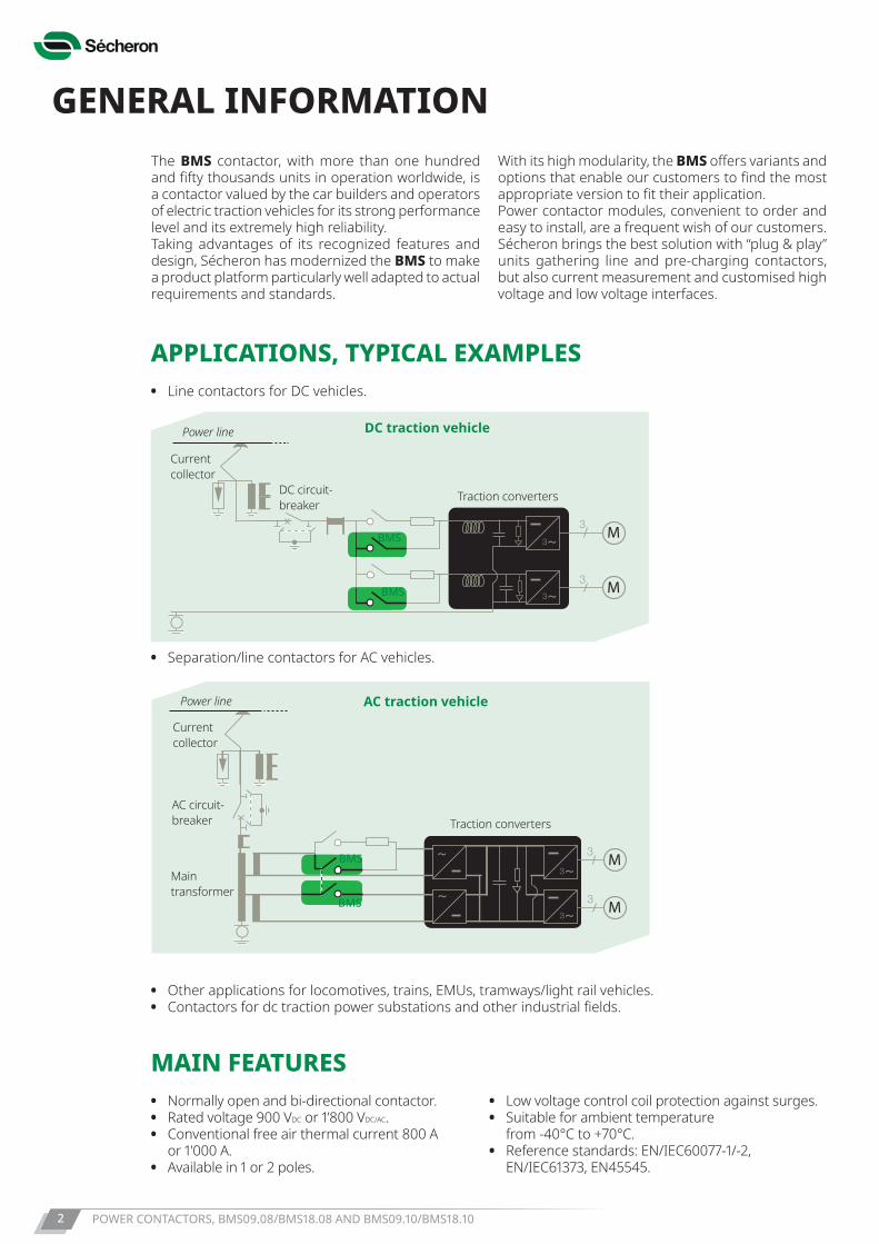
APPLICATIONS, TYPICAL EXAMPLES• Line contactors for DC vehicles.
• Separation/line contactors for AC vehicles.
• Other applications for locomotives, trains, EMUs, tramways/light rail vehicles.• Contactors for dc traction power substations and other industrial fields.
~
M
M
3
33
~3
M
M
~
~~3
~3
3
3
Current collector
Power line
DC circuit- breaker
Traction converters
DC traction vehicle
BMS
BMS
~
M
M
3
33
~3
M
M
~
~~3
~3
3
3
Current collector
Power line
AC circuit- breaker
Main transformer
Traction converters
AC traction vehicle
BMS
BMS
The BMS contactor, with more than one hundred and fifty thousands units in operation worldwide, is a contactor valued by the car builders and operators of electric traction vehicles for its strong performance level and its extremely high reliability.Taking advantages of its recognized features and design, Sécheron has modernized the BMS to make a product platform particularly well adapted to actual requirements and standards.
With its high modularity, the BMS offers variants and options that enable our customers to find the most appropriate version to fit their application.Power contactor modules, convenient to order and easy to install, are a frequent wish of our customers. Sécheron brings the best solution with “plug & play” units gathering line and pre-charging contactors, but also current measurement and customised high voltage and low voltage interfaces.
POWER CONTACTORS, BMS09.08/BMS18.08 AND BMS09.10/BMS18.10 3
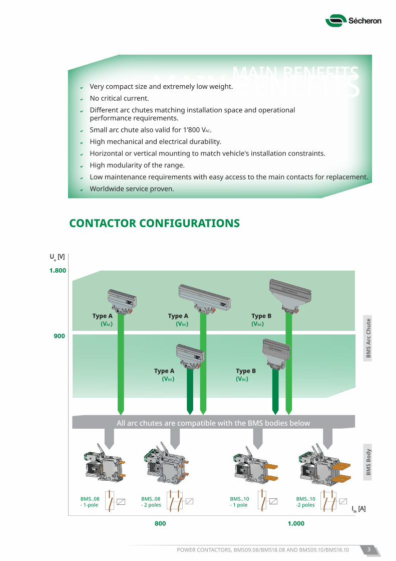
Ue [V]
900
1.800
800
Ue [V]
1.800
Ith [A]
1.000
PCC18 for horizontal mountingh only
BM
S
PC
C1
8
CONTACTOR CONFIGURATIONS
Type A(VDC)
BMS
Body
Type A(VDC)
Type A(VAC)
Type B(VDC)
Type B(VDC)
All arc chutes are compatible with the BMS bodies below
BMS
Arc
Chut
e
MAIN BENEFITS
BMS..08- 1-pole
BMS..08- 2 poles
BMS..10- 1 pole
BMS..10-2 poles
MAIN BENEFITS Very compact size and extremely low weight. No critical current. Differentarcchutesmatchinginstallationspaceandoperational
performance requirements. Small arc chute also valid for 1’800 VAC. High mechanical and electrical durability. Horizontal or vertical mounting to match vehicle's installation constraints. High modularity of the range. Low maintenance requirements with easy access to the main contacts for replacement. Worldwide service proven.
POWER CONTACTORS, BMS09.08/BMS18.08 AND BMS09.10/BMS18.104
DATA FOR PRODUCT SELECTION
LOW VOLTAGE CIRCUITControl circuit 1 pole 2 polesNominal supply voltage / Nominal control voltage Un/UEF [Vdc] 24 to 220 / 24 to 220 (2) 24 to 110 / 24 to 110 (2)
Range of voltage [0.7 - 1.25] Un
Nominal closing power (3) Pc [W] ≤ 37, ≤ 60, ≤ 80, ≤ 250 (2)
Nominal holding power (3) Ph [W] ≤ 4, ≤ 6, ≤ 37 (2)
Mechanical closing time tcc [ms] 150Mechanical opening time (3) tco [ms] 50
(2) For detailed values based on BMS configuration, please refer to page 9 • (3) At Un and Tamb = +20°C. Auxiliary contactsType of contacts Potential free (PF)Rated voltage [VDC] 24 to 220Conventional thermal current Ith [A] 10Utilization category according to EN60947- AC-15 230 VAC 1.0 A- DC-13 110 VDC 0.5 AMinimum let-through current at 24 Vdc (4) [mA] ≥ 10 (silver contacts) or 4 ≤ I < 10 (gold contacts)
(4) For a dry and clean environment.
Low voltage interfaceControl circuits Direct on coil or Wago terminal (based on product configuration)Auxiliary switches Direct on switches
InsulationRated power-frequency withstand voltage (50 Hz / 1min)- LV circuit to earth U50 [kV] 1.5
OPERATING CONDITIONSInstallation IndoorAltitude [m] ≤ 1’400Working ambient temperature Tamb [°C] - 40 to + 70Humidity 95% at + 40°CPollution degree PD3AMinimum mechanical durability N Cycles 2 millions (BMS..08) / 1 million (BMS..10)
Symbol UnitBMS
09.08BMS09.10
BMS09.08
BMS18.08
BMS18.10
BMS18.08
MAIN HIGH VOLTAGE CIRCUITArc chute type A A B A A BComponent category A2Type of main contact Normally OpenNumber of poles 1 pole, 2 polesRated operational voltage-dc voltage Ue [VDC] 900 1’800-ac voltage (16.7, 25, 50/60, ...400 Hz) [VAC] 1’800 - -Rated insulation voltage Ui [VDC] 2’300 2’300
[VAC] 2’300 - -Conventional free air thermal current (1) Ith [A] 800 (BMS..08) 800 (BMS..08)
1’000 (BMS..10) 1’000 (BMS..10)Rated operational current/operational frequency- Horizontal mounting: Ie [ADC] 800 / C1 800/C2 800 / C1 800 / C1
Ie [ADC] 500 / C2 - 500 / C2 -[AAC] 800 / C2 - - -
- Vertical mounting: Ie [ADC] 500 / C1 800 / C1 500 / C1 800 / C1[AAC] 800 / C1 - 800 / C1 -
Rated short-time withstand current Icw / t [kA]/[ms] 10 / 100 10 / 100Peak short-time withstand current Îcw [kA] 10 10Maximum breaking capacity-dc current, τ = 15 ms Ibc [A] 3’200 6’000 2’300 6’000- ac current, cos Φ = 0.8 (16.7, 25 & 50/60 Hz) Ibc [A] 4’200 - - -Maximum making capacity- dc current, τ = 15 ms Imc [A] 6’000 6’000- ac current, cos Φ = 0.8 (16.7, 25 & 50/60 Hz) Ibc [Apeak] 6’000 - -Rated power-frequency withstand voltage (50 Hz/1min)- Between main contacts (open) U50 [kVAC] 7.5 7.5- Main circuit (closed) to earth U50 [kVAC] 9.5 9.5(1) At Tamb = +40°C for DC and AC voltage up to 60 Hz, and tested with HV connections with current density 1.7A/mm2. For higher frequency, please contact Sécheron.
POWER CONTACTORS, BMS09.08/BMS18.08 AND BMS09.10/BMS18.10 5
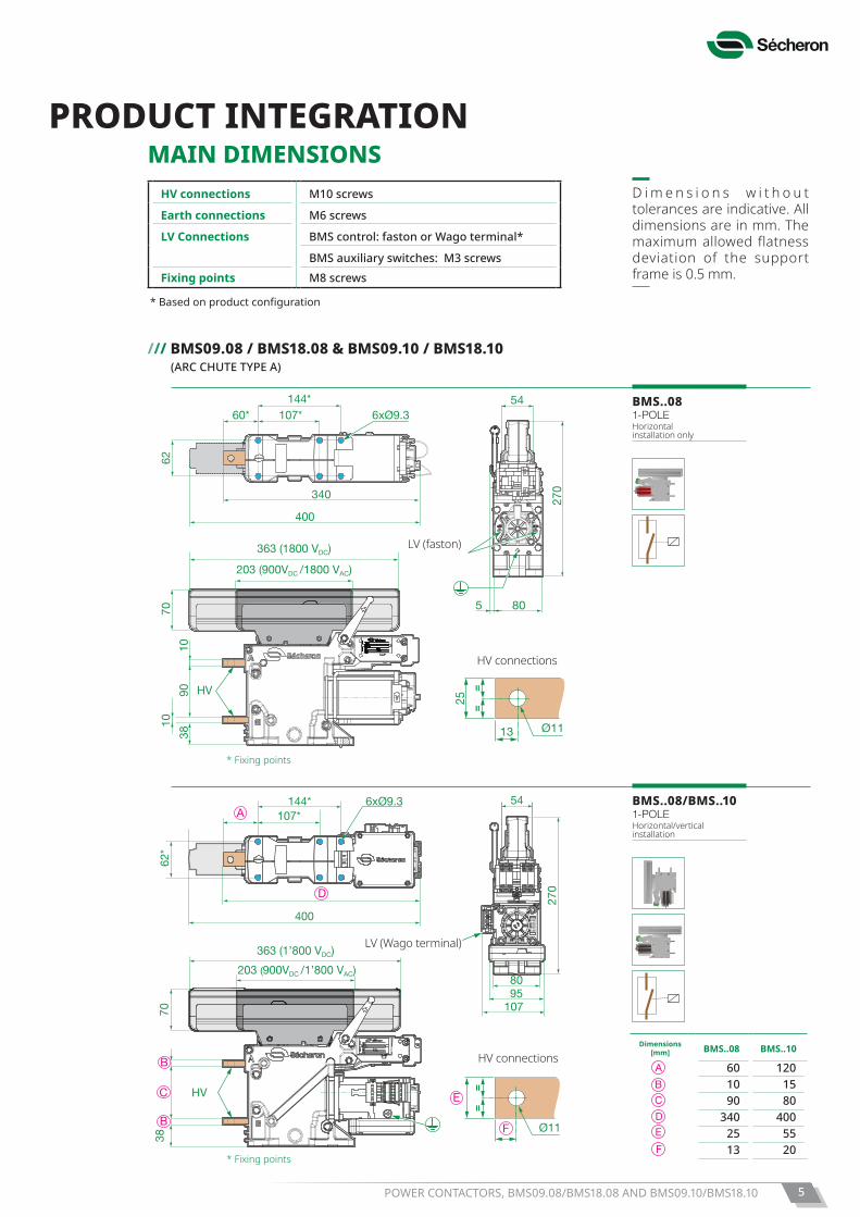
PRODUCT INTEGRATIONMAIN DIMENSIONS
/// BMS09.08 / BMS18.08 & BMS09.10 / BMS18.10 (ARC CHUTE TYPE A)
BMS..081-POLEHorizontal installation only
BMS..08/BMS..101-POLEHorizontal/vertical installation
D i m e n s i o n s w i t h o u t tolerances are indicative. All dimensions are in mm. The maximum allowed flatness deviation of the support frame is 0.5 mm.
HV connections
70
9038
10
10
340
80
270
54
400
HV
62
144* 107*60*
363 (1800 VDC)
203 (900VDC /1800 VAC)
5
6xØ9.3
25
=
=
Ø1113
70
9038
10
10
340
80
270
54
400
HV
62
144* 107*60*
363 (1800 VDC)
203 (900VDC /1800 VAC)
5
6xØ9.3
25
=
=
Ø1113
62*
144*107*
70
HV
270
8095
107
54A
400
363 (1’800 VDC)
203 (900VDC /1’800 VAC)
38
B
E
B
C
D
6xØ9.3
=
=
Ø11F
*Basedonproductconfiguration
LV (Wago terminal)
HV connections M10 screws
Earth connections M6 screws
LV Connections BMS control: faston or Wago terminal*
BMS auxiliary switches: M3 screwsFixing points M8 screws
LV (faston)
HV connections
* Fixing points
* Fixing points
Dimensions [mm] BMS..08 BMS..10
60 120 10 15 90 80
340 400 25 55 13 20
POWER CONTACTORS, BMS09.08/BMS18.08 AND BMS09.10/BMS18.106
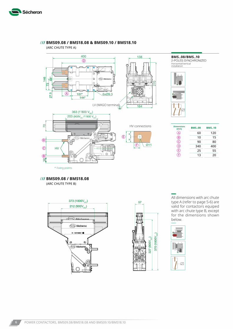
/// BMS09.08 / BMS18.08 & BMS09.10 / BMS18.10 (ARC CHUTE TYPE A)
/// BMS09.08 / BMS18.08 (ARC CHUTE TYPE B)
370
(180
0VD
C)
212 (900VDC)
373 (1800VDC) 57
327
(900
VD
C)
370
(180
0VD
C)
212 (900VDC)
373 (1800VDC) 57
327
(900
VD
C)
All dimensions with arc chute type A (refer to page 5-6) are valid for contactors equiped with arc chute type B, except for the dimensions shown below.
BMS..08/BMS..102-POLES SYNCHRONIZEDHorizontal/vertical installation
70
HV
363 (1’800 VDC)203 (900VDC /1’800 VAC)
38
B
B
C
A
D
146
73
144*107*
138
164
270
27.5
84*
400
6xØ9.3
E=
=
Ø11F
Dimensions [mm] BMS..08 BMS..10
60 120 10 15 90 80
340 400 25 55 13 20
HV connections
LV (WAGO terminal)
* Fixing points
POWER CONTACTORS, BMS09.08/BMS18.08 AND BMS09.10/BMS18.10 7
270
8095
107
54 138
164
270
1-pole:BMS09.08ABMS18.08ABMS09.10ABMS18.10A(Horizontal / Vertical)
2-poles:BMS09.08/2ABMS18.08/2A(Horizontal / Vertical)
1-pole:BMS09.08BBMS18.08B(Horizontal only)
370
(BM
S18
..)
327(
BM
S09
..)
327
(BM
S09
..)
327
(BM
S09
..)
80
56 56
370
(BM
S18
..)
8095
1-pole:BMS09.08BBMS18.08B(Horizontal / Vertical)
80
270
54
1-pole:BMS09.08ABMS18.08A(Horizontal only)
107
370
(BM
S18
..)
16495
56 56
2-poles:BMS09.08/2BBMS18.08/2B(Horizontal / Vertical)
270
8095
107
54 138
164
270
1-pole:BMS09.08 A**BMS18.08 A**BMS09.10 ABMS18.10 A(**Vertical)
2-poles:BMS09.08/2 ABMS18.08/2 A
1-pole:BMS09.08 B*BMS18.08 B*(*Horizontal)
327
80
56 56
327
8095
1-pole:BMS09.08 B**BMS18.08 B**BMS09.10 BBMS18.10 B(**Vertical)
80
270
54
1-pole:BMS09.08 A*BMS18.08 A*(*Horizontal)
10716495
56 56
2-poles:BMS09.08/2 BBMS18.08/2 B
270
8095
107
54 138
164
270
1-pole:BMS09.08ABMS18.08ABMS09.10ABMS18.10A(Horizontal / Vertical)
2-poles:BMS09.08/2ABMS18.08/2A(Horizontal / Vertical)
1-pole:BMS09.08BBMS18.08B(Horizontal only)
370
(BM
S18
..)
327(
BM
S09
..)
327
(BM
S09
..)
327
(BM
S09
..)
80
56 56
370
(BM
S18
..)
8095
1-pole:BMS09.08BBMS18.08B(Horizontal / Vertical)
80
270
54
1-pole:BMS09.08ABMS18.08A(Horizontal only)
107
370
(BM
S18
..)
16495
56 56
2-poles:BMS09.08/2BBMS18.08/2B(Horizontal / Vertical)
270
8095
107
54 138
164
270
1-pole:BMS09.08 A**BMS18.08 A**BMS09.10 ABMS18.10 A(**Vertical)
2-poles:BMS09.08/2 ABMS18.08/2 A
1-pole:BMS09.08 B*BMS18.08 B*(*Horizontal)
327
80
56 56
327
8095
1-pole:BMS09.08 B**BMS18.08 B**BMS09.10 BBMS18.10 B(**Vertical)
80
270
54
1-pole:BMS09.08 A*BMS18.08 A*(*Horizontal)
10716495
56 56
2-poles:BMS09.08/2 BBMS18.08/2 B
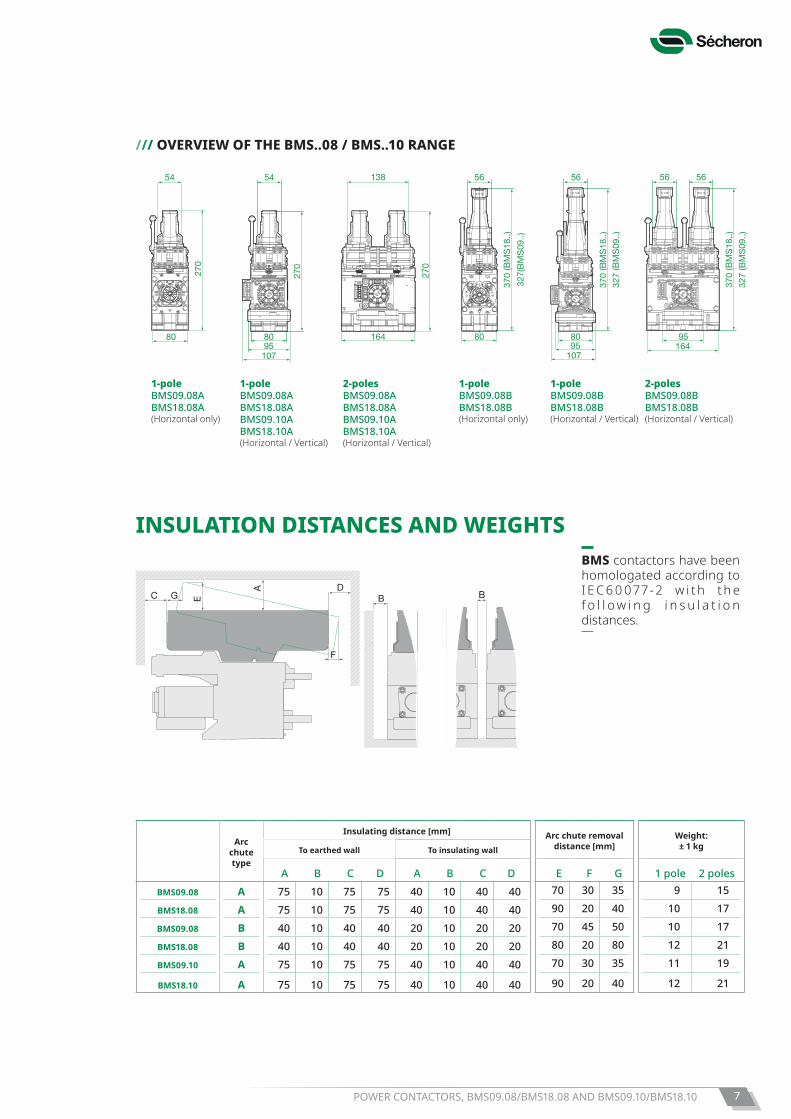
/// OVERVIEW OF THE BMS..08 / BMS..10 RANGE
270
8095
107
54 138
164
270
1-pole:BMS09.08ABMS18.08ABMS09.10ABMS18.10A(Horizontal / Vertical)
2-poles:BMS09.08/2ABMS18.08/2A(Horizontal / Vertical)
1-pole:BMS09.08BBMS18.08B(Horizontal only)
370
(BM
S18
..)
327(
BM
S09
..)
327
(BM
S09
..)
327
(BM
S09
..)
80
56 56
370
(BM
S18
..)
8095
1-pole:BMS09.08BBMS18.08B(Horizontal / Vertical)
80
270
54
1-pole:BMS09.08ABMS18.08A(Horizontal only)
107
370
(BM
S18
..)
16495
56 56
2-poles:BMS09.08/2BBMS18.08/2B(Horizontal / Vertical)
270
8095
107
54 138
164
270
1-pole:BMS09.08 A**BMS18.08 A**BMS09.10 ABMS18.10 A(**Vertical)
2-poles:BMS09.08/2 ABMS18.08/2 A
1-pole:BMS09.08 B*BMS18.08 B*(*Horizontal)
327
80
56 56
327
8095
1-pole:BMS09.08 B**BMS18.08 B**BMS09.10 BBMS18.10 B(**Vertical)
80
270
54
1-pole:BMS09.08 A*BMS18.08 A*(*Horizontal)
10716495
56 56
2-poles:BMS09.08/2 BBMS18.08/2 B
1-poleBMS09.08ABMS18.08ABMS09.10ABMS18.10A(Horizontal / Vertical)
2-polesBMS09.08ABMS18.08A BMS09.10ABMS18.10A(Horizontal / Vertical)
1-poleBMS09.08BBMS18.08B(Horizontal only)
1-poleBMS09.08BBMS18.08B(Horizontal / Vertical)
2-polesBMS09.08BBMS18.08B(Horizontal / Vertical)
1-poleBMS09.08ABMS18.08A(Horizontal only)
DDBB
FF
AA
EECC GG BB
INSULATION DISTANCES AND WEIGHTS
Arc chute type
Insulating distance [mm] Arc chute removal distance [mm]
Weight: ± 1 kgTo earthed wall To insulating wall
A B C D A B C D E F G 1 pole 2 polesBMS09.08 A 75 10 75 75 40 10 40 40 70 30 35 9 15
BMS18.08 A 75 10 75 75 40 10 40 40 90 20 40 10 17
BMS09.08 B 40 10 40 40 20 10 20 20 70 45 50 10 17
BMS18.08 B 40 10 40 40 20 10 20 20 80 20 80 12 21
BMS09.10 A 75 10 75 75 40 10 40 40 70 30 35 11 19
BMS18.10 A 75 10 75 75 40 10 40 40 90 20 40 12 21
BMS contactors have been homologated according to I E C 6 0 0 7 7 - 2 w i t h t h e f o l l o w i n g i n s u l a t i o n distances.
POWER CONTACTORS, BMS09.08/BMS18.08 AND BMS09.10/BMS18.108
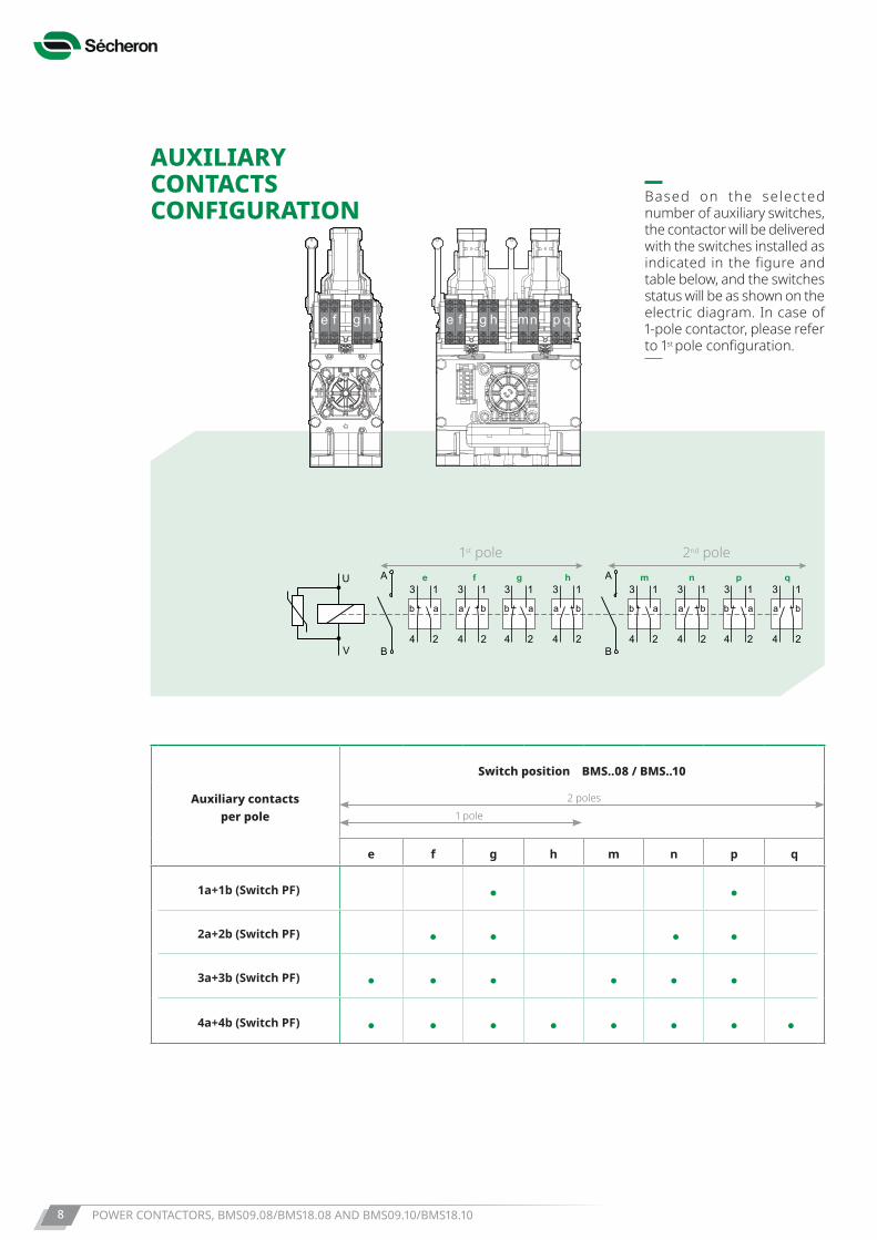
AUXILIARY CONTACTS CONFIGURATION
B
A
2
13
4B
AU
V 2
13
4 2
13
4 2
13
4
ab a b ab a b
2
13
4 2
13
4 2
13
4 2
13
4
ab a b ab a b
e f mhg n p q
fe g h m p qn
Based on the selected number of auxiliary switches, the contactor will be delivered with the switches installed as indicated in the figure and table below, and the switches status will be as shown on the electric diagram. In case of 1-pole contactor, please refer to 1st pole configuration.
Auxiliary contacts per pole
Switch position BMS..08 / BMS..10
e f g h m n p q
1a+1b (Switch PF)
2a+2b (Switch PF)
3a+3b (Switch PF)
4a+4b (Switch PF)
1 pole2 poles
ee f mhh gf g n p q
1st pole 2nd pole
POWER CONTACTORS, BMS09.08/BMS18.08 AND BMS09.10/BMS18.10 9
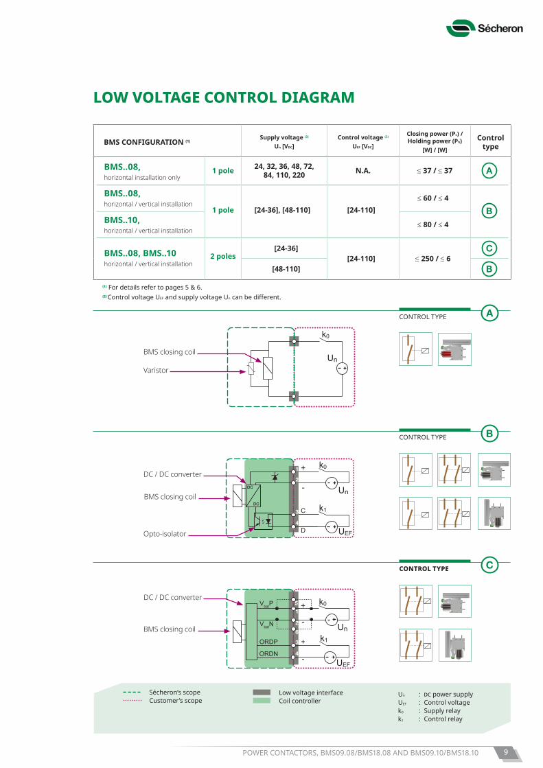
Sécheron’s scope Customer’s scope
Low voltage interface Coil controller
Un : dc power supplyUEF : Control voltagek0 : Supply relayk1 : Control relay
LOW VOLTAGE CONTROL DIAGRAM
BMS CONFIGURATION (1)Supply voltage (2)
Un [VDC]Control voltage (2)
UEF [VDC]
Closing power (Pc) / Holding power (Ph)
[W] / [W]
Control type
BMS..08,horizontal installation only
1 pole 24, 32, 36, 48, 72, 84, 110, 220 N.A. ≤ 37 / ≤ 37
BMS..08,horizontal / vertical installation
1 pole [24-36], [48-110] [24-110]≤ 60 / ≤ 4
BMS..10,horizontal / vertical installation
≤ 80 / ≤ 4
BMS..08, BMS..10horizontal / vertical installation
2 poles [24-36]
[24-110] ≤ 250 / ≤ 6[48-110]
Un
k0
BMS closing coil
Varistor
DC
DC
+
-
C
D
Un
k1
k0
UEF
1
2
3
4
DC / DC converter
Opto-isolator
BMS closing coil
+
-
+
-
Unk1
k0
UEF
1
2
3
4
5
6
VbatP
VbatN
ORDP
ORDN
DC / DC converter
BMS closing coil
CONTROL TYPE
CONTROL TYPE
CONTROL TYPE
Auxiliary contacts per pole
Switch position BMS..08 / BMS..10
e f g h m n p q
1a+1b (Switch PF)
2a+2b (Switch PF)
3a+3b (Switch PF)
4a+4b (Switch PF)
(1) For details refer to pages 5 & 6.(2) Control voltage UEF and supply voltage Uncanbedifferent.
POWER CONTACTORS, BMS09.08/BMS18.08 AND BMS09.10/BMS18.1010
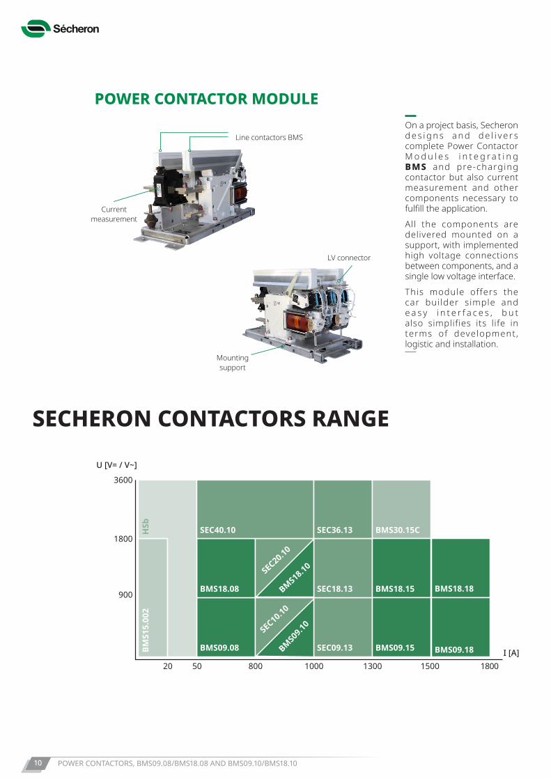
Mounting support
LV connector
Current measurement
Line contactors BMSOn a project basis, Secheron d e s i g n s a n d d e l i v e r s complete Power Contactor M o d u l e s i n t e g r a t i n g BMS and pre-charging contactor but also current measurement and other components necessary to fulfill the application.All the components are delivered mounted on a support, with implemented high voltage connections between components, and a single low voltage interface.This module offers the car builder simple and e a s y i n t e r f a c e s , b u t also simplifies its life in terms of development, logistic and installation.
SECHERON CONTACTORS RANGE
POWER CONTACTOR MODULE
180015001000 13008005020
900
1800
3600
I [A]
U [V= / V~]
HSb
BMS1
5.00
2
BMS18.18
BMS09.18
BMS18.08
BMS09.08
SEC18.13
SEC40.10 SEC36.13
SEC09.13
BMS18.15
BMS30.15C
BMS09.15
SEC20.10
BMS18.10
SEC10.10
BMS09.10
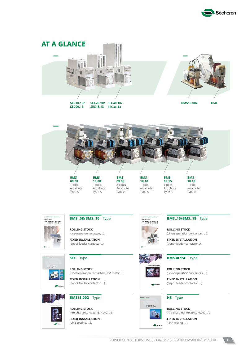
BMS09.081 poleArc chuteType A
BMS18.081 poleArc chuteType A
BMS09.082 polesArc chuteType A
BMS18.101 poleArc chuteType A
BMS09.151 poleArc chuteType A
BMS18.181 poleArc chuteType A
BMS15.002 HSBSEC20.10/SEC18.13
SEC10.10/SEC09.13
SEC40.10/SEC36.13
POWER CONTACTORS, BMS09.08/BMS18.08 AND BMS09.10/BMS18.10 11
BMS..08/BMS..10 Type
ROLLING STOCK(Line/separation contactors, ...).
FIXED INSTALLATION(depot feeder contactor...).
BMS..15/BMS..18 Type
ROLLING STOCK (Line/separation contactors, ...).
FIXED INSTALLATION(depot feeder contactor...).
SEC Type
ROLLING STOCK (Line/separation contactors, PM motor,...).
FIXED INSTALLATION(depot feeder contactor, ...).
BMS30.15C Type
ROLLING STOCK (Line/separation contactors, ...).
FIXED INSTALLATION(depot feeder contactor, ...).
BMS15.002 Type
ROLLING STOCK (Pre-charging, Heating, HVAC, ...).
FIXED INSTALLATION(Line testing, ...).
HS Type
ROLLING STOCK(Pre-charging, Heating, HVAC, ...).
FIXED INSTALLATION(Line testing, ...).
AT A GLANCE
Copyright© 2019 Sécheron SA
This document is not contractual and contains information corresponding to the level of technology at the date of printing. Sécheron reserves the right to modify and/or improve the product, whose characteristics are described in these documents, as required by new technology at any time. It is the purchaser’s responsibility to inform himself, no matter what the circumstances, of the product’s maintenance conditions and requirements. Sécheron reserves all rights, especially those arising from our “General Delivery Conditions”.
SG20
2168
BEN
_B11
-01.1
9
Sécheron SA Rue du Pré-Bouvier 251242 Satigny - GenevaCH-Switzerland
Tel: +41 22 739 41 11Fax: +41 22 739 48 [email protected]
Pla
ce a
nd d
ate:
N
ame:
S
igna
ture
:
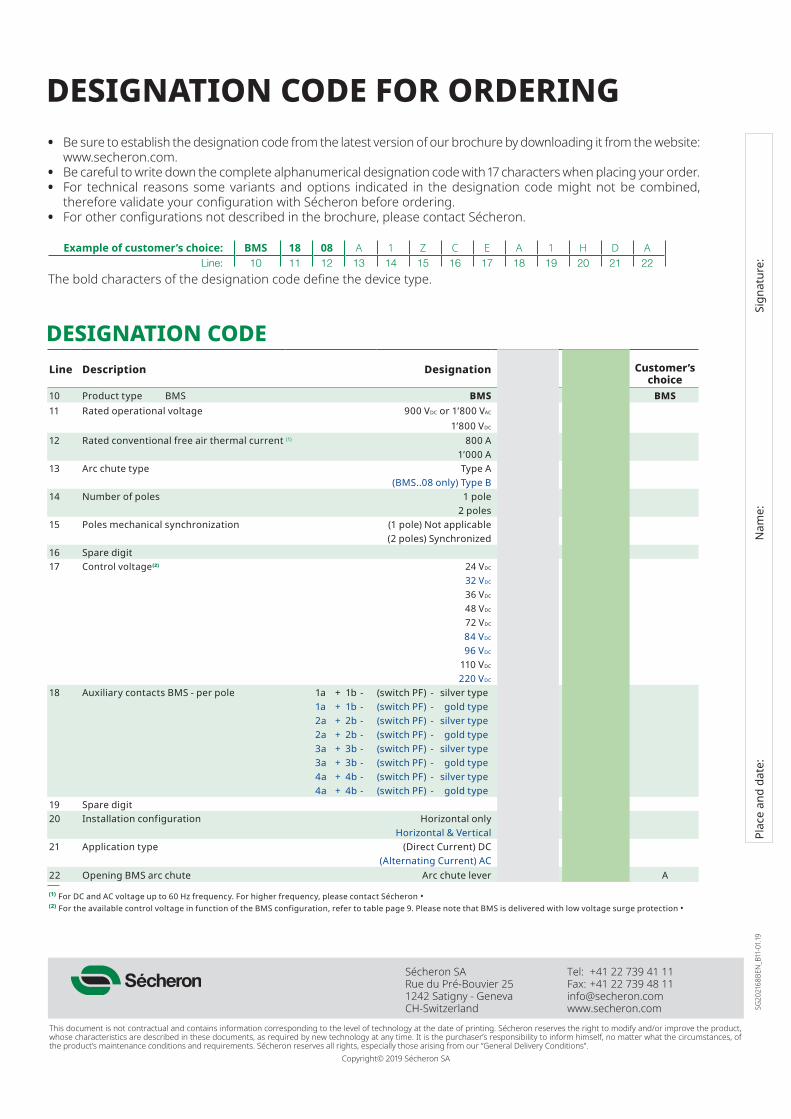
DESIGNATION CODE FOR ORDERING• Be sure to establish the designation code from the latest version of our brochure by downloading it from the website:
www.secheron.com.• Be careful to write down the complete alphanumerical designation code with 17 characters when placing your order.• For technical reasons some variants and options indicated in the designation code might not be combined,
therefore validate your configuration with Sécheron before ordering.• For other configurations not described in the brochure, please contact Sécheron.
Example of customer’s choice: BMS 18 08 A 1 Z C E A 1 H D ALine: 10 11 12 13 14 15 16 17 18 19 20 21 22
The bold characters of the designation code define the device type.
DESIGNATION CODELine Description Designation Standard Options Customer’s
choice10 Product type BMS BMS BMS BMS11 Rated operational voltage 900 VDC or 1’800 VAC 09
1’800 VDC 1812 Rated conventional free air thermal current (1) 800 A 08
1’000 A 1013 Arc chute type Type A A
(BMS..08 only) Type B B14 Number of poles 1 pole 1
2 poles 215 Poles mechanical synchronization (1 pole) Not applicable Z
(2 poles) Synchronized S16 Spare digit Ø17 Control voltage(2) 24 VDC A
32 VDC F36 VDC B48 VDC C72 VDC D84 VDC H96 VDC 4
110 VDC E220 VDC J
18 Auxiliary contacts BMS - per pole 1a + 1b - (switch PF) - silver type A1a + 1b - (switch PF) - gold type C2a + 2b - (switch PF) - silver type E2a + 2b - (switch PF) - gold type H3a + 3b - (switch PF) - silver type K3a + 3b - (switch PF) - gold type M4a + 4b - (switch PF) - silver type O4a + 4b - (switch PF) - gold type P
19 Spare digit Z20 Installation configuration Horizontal only H
Horizontal & Vertical V21 Application type (Direct Current) DC D
(Alternating Current) AC A22 Opening BMS arc chute Arc chute lever A A
(1) For DC and AC voltage up to 60 Hz frequency. For higher frequency, please contact Sécheron • (2) For the available control voltage in function of the BMS configuration, refer to table page 9. Please note that BMS is delivered with low voltage surge protection •


![RStandard Pole Design Guide - Composite Utility Poles Poles Pole Design... · RStandard Pole Design Guide ... pole structures the M1L should only be used in poles up to 65 ft. [15.2m]](https://static.fdocuments.net/doc/165x107/5a8140f87f8b9a9d308d1097/rstandard-pole-design-guide-composite-utility-poles-pole-designrstandard-pole.jpg)


