
CONTACT RECEIVING .doc
65
Contact Receiving Mobile Phone Application Using GPRS By Shagufta Yaseen Supervised by Ata Ullah
-
Upload
telecomnuml8233 -
Category
Documents
-
view
221 -
download
0
Transcript of CONTACT RECEIVING .doc
Contact Receiving Mobile Phone Application Using GPRS
ByShagufta Yaseen
Supervised byAta Ullah
DEPARTMENT OF INFORMATION TECHNOLOGY NATIONAL UNIVERSITY OF MODERN LANGUAGES ISLAMABAD
November 2011
Certificate
Dated: ___________
Final Approval
It is certified that the project report submitted by Shagufta Yaseen for the partial fulfillment of the requirement of Masters Degree in Computer Science is approved.
COMMITTEE
Dean IT and Engineering:
Dr. M. AkbarSignature: ____________________
Head IT:
Mr. Naveed AlamSignature: ____________________
Head Project Committee:
Mr. Ata UllahSignature: ____________________
Supervisor:
Mr. Ata UllahSignature: ____________________
ABSTRACT
“Contact Receiving Mobile Phone Application Using GPRS” is GPRS based mobile Phone Application which is particularly developed to search and receive any contact number from one cell phone to any other cell phone. Mobiles are becoming an inevitable part of modern society. People use mobiles to make calls, to send and read SMS, to store contact information, to store person files, photos, videos and music etc. Mobiles so became an important retrieve data device with lot of personal and business related information and messages. The necessity of the information retrive is increased in this context. The project concerns developing a simple mobile application softwre to allow the user to make a access contact of the phonebook entries stored on the mobile devices and SIM card, to a other mobile using GPRS. Using over GPRS the SIM card information such as contacts, messages, and call history can be transferred between the mobile device and the server. The main advantage of the software is that it automatically sends incoming message, call history to server. The system comprises of a server application running on computer to receive the requests from clients. Firstly you need to signup using using server logon and password. It provides you login and password. Using this login and password you can retrive your mobile. Login request is send to server to retrive mobile when we need. Secondly a log out request is sent to leave the network. This mobile application run on every mobile.
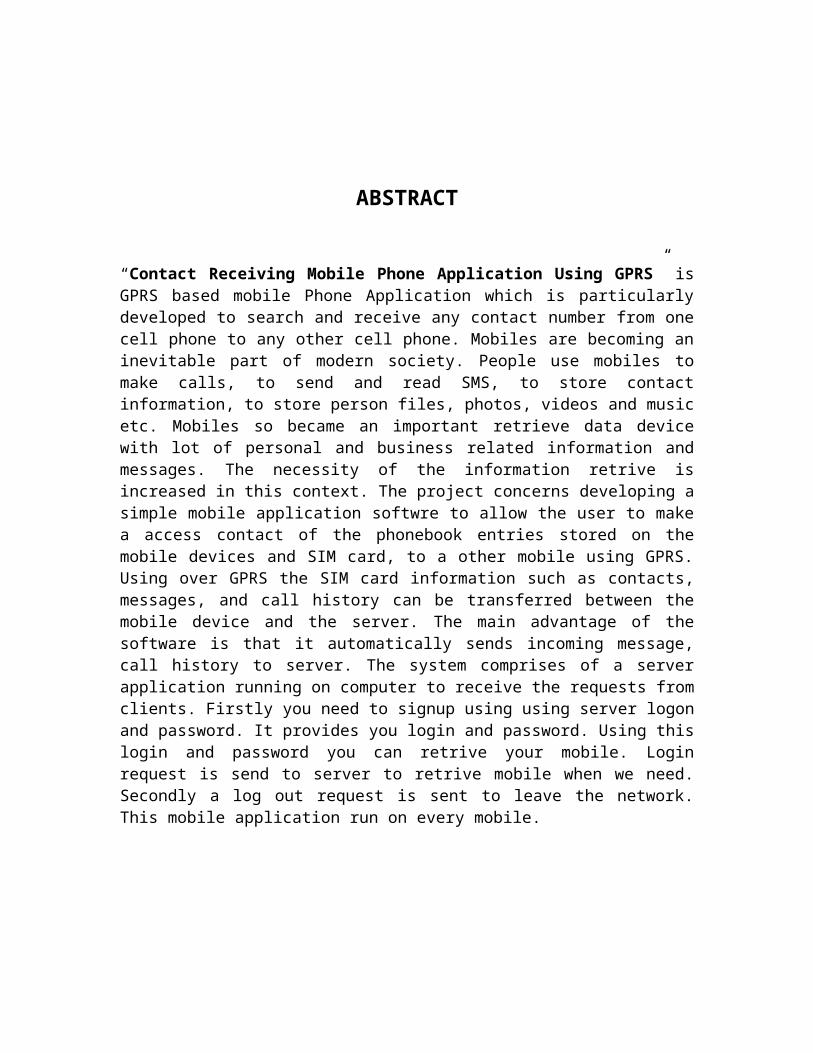
Table of Contents .
Table of Contents
CHAPTER 1: INTRODUCTION...........................................................................................................1
1.1 Project Overview...................................................................................................................... 1
1.2 Problem Statement................................................................................................................... 1
1.3 Objectives................................................................................................................................. 2
1.4 Project Features....................................................................................................................... 2
1.5 Server Features........................................................................................................................ 2
1.6 Client Features......................................................................................................................... 2
1.7 User Description....................................................................................................................... 31.7.1 Server side....................................................................................................................................31.7.2 Client side.....................................................................................................................................3
1.8 Hardware Requirements..........................................................................................................3
1.9 Software Requirements............................................................................................................ 3
1.10 Tools and Technologies Used...................................................................................................31.10.1 NetBeans and J2ME.................................................................................................................3
CHAPTER 2: REQUIREMENTS SPECIFICATION......................................................7
2.1 Functional Requirements.........................................................................................................72.1.1 Server Module..............................................................................................................................72.1.2 Client Module...............................................................................................................................8
2.2 Non Functional Requirements.................................................................................................8
CHAPTER 3: SYSTEM ANALYSIS.................................................................................... 9
3.1 Evaluation of Existing System..................................................................................................9
3.2 Proposed System...................................................................................................................... 9
3.3 Use Cases................................................................................................................................ 103.3.1 Main Use Case Diagram:............................................................................................................103.3.2 Use Case Name: Mobile Number Entering.................................................................................133.3.3 Use Case Name: Enters Contact.................................................................................................16
Table of Contents .
3.3.4 Use Case Name: Send Contact...................................................................................................19
CHAPTER 4: SYSTEM DESIGN....................................................................................... 21
4.1 Architecture Diagram............................................................................................................ 214.1.1 Client Functionality....................................................................................................................224.1.2 Server Functionality...................................................................................................................224.1.3 Architecture Overview....................................................................................................................23
4.2 Sequence Diagrams................................................................................................................ 304.2.1 Login Sequence Diagram...........................................................................................................304.2.2 Mobile Backup Sequence Diagram.................................................................................................31
4.3 Class Diagrams............................................................................................................................. 324.3.1Server Side......................................................................................................................................324.3.2Client Side.......................................................................................................................................35
CHAPTER 5: SYSTEM IMPLEMENTATION..............................................................21
5.1 Development Objectives achieved..........................................................................................225.1.1 Server Side.................................................................................................................................225.1.2 Client Side..................................................................................................................................23
5.2 Development Track................................................................................................................ 23
5.3 Development and Build Environment....................................................................................245.3.1 Hardware Requirements.............................................................................................................245.3.2 Software Requirements...............................................................................................................24
5.4 Overall Deployment Strategy.................................................................................................245.4.1 Hardware Requirements.............................................................................................................255.4.2 Software Requirements...............................................................................................................25
5.5 Screen Shots........................................................................................................................... 255.5.1 Server.........................................................................................................................................255.5.2 Client Login Page.......................................................................................................................265.5.3 Remote Contact Recieving.........................................................................................................26
CHAPTER 6: SYSTEM TESTING....................................................................................21
6.1 Test Cases............................................................................................................................... 216.1.1 Test Case Name: Login..............................................................................................................216.1.2 Test Case Name: Send Contact Name........................................................................................226.1.3 Test Case Name: Receive Contact Details..................................................................................226.1.4 Test Case Name: Logout............................................................................................................24
Table of Contents .
1
Chapter 1 Introduction
Chapter 1: Introduction
1.1 Project Overview
The Main objective of this project was to achieve search contact in a very cost effective manner.
Approach adopted is that to find contact through GPRS. The scope includes of building a server,
client. Client will run on a cellular device and server will also run on cellular. Development
methodology which is adopted is RAD. Each module of the system is developed and deployed
iteratively. After the deployment of each module whole of the functionality of the software is
tested. First prototype of each of the module is created. Functionality is implemented in that
module according to the requirement. After the completion of the module its functionality is
tested in accordance to the requirements and after the successful testing that module is integrated
in the existing software and complete software is tested again. Total budget estimated for the
development is approximately 7,000 PKR. Total time estimated for development and testing is
approximately 300 days. This is an innovative project and a lot of research is required that is why
requirement are elaborated from different sources according to the needs of the solutions.
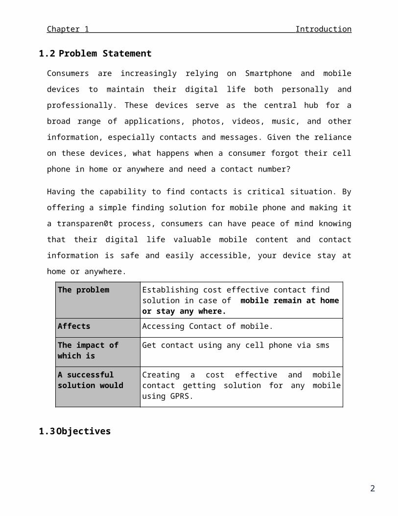
1.2 Problem Statement
Consumers are increasingly relying on Smartphone and mobile devices to maintain their digital
life both personally and professionally. These devices serve as the central hub for a broad range
of applications, photos, videos, music, and other information, especially contacts and messages.
Given the reliance on these devices, what happens when a consumer forgot their cell phone in
home or anywhere and need a contact number?
Having the capability to find contacts is critical situation. By offering a simple finding solution
for mobile phone and making it a transparen0t process, consumers can have peace of mind
knowing that their digital life valuable mobile content and contact information is safe and easily
accessible, your device stay at home or anywhere.
2
Chapter 1 Introduction
The problem Establishing cost effective contact find solution in case of mobile remain at home or stay any where.
Affects Accessing Contact of mobile.
The impact of which is Get contact using any cell phone via sms
A successful solution would
Creating a cost effective and mobile contact getting solution for any mobile using GPRS.
1.3 Objectives
Following are the objectives that are required to be meet in order for the project to be successful.
Creating a communication infrastructure.
Communication is cost effective.
Infrastructure is mobile in nature.
Infrastructure is easy to configure.
1.4 Project Features
There are two major parts of this project. Mobile based server and mobile based client.
1.5 Server Features
Listening on GPRS for connectivity Accepting an incoming connection request from client. Full fill client requirement.
1.6 Client Features
Request for connectivity on GPRS for connectivity with the server. Send Request for getting a contact via sms.
3
Chapter 1 Introduction
1.7 User Description
Users are divided into two categories. Server side users.
Client side users.
1.7.1 Server side
Server side is that mobile which forgot and stayed at home or anywhere.
1.7.2 Client side
Client side user can be anyone with a cell phone device with the client side software.
1.8 Hardware Requirements
There were following Hardware requirements: Mobile Device(s).
1.9 Software Requirements
To make this idea happened we required some certain technologies like Windows XP,Windows vista,Windows 7 Netbeans
1.10 Tools and Technologies Used
1.10.1 NetBeans and J2ME
4
Chapter 1 Introduction
NetBeans refers to both a platform framework for Java desktop applications, and an integrated
development environment (IDE) for developing with Java, JavaScript, PHP, Python, Groovy, C,
C++, and others. The NetBeans IDE 7.0 no longer supports Ruby and Ruby on Rails.
The NetBeans IDE is written in Java and can run anywhere a compatible JVM is installed,
including Windows, Mac OS, Linux, and Solaris. A JDK is required for Java development
functionality, but is not required for development in other programming languages. The
NetBeans platform allows applications to be developed from a set of modular software
components called modules. Applications based on the NetBeans platform (including the
NetBeans IDE) can be extended by third party developers.
1.10.1.1 What is J2ME or Java ME?
Primary components of the Java Platform, Micro Edition (Java ME, formerly J2ME) include
Connected Device Configurations, Connected Limited Device Configurations, Mobile
Information Device Profiles, along with many other tools and technologies that address Java
solutions for the consumer and embedded device markets. Take your first step into learning more
about these technologies. Definitions of terms, and what these new concepts can mean to you are
available on the java.sun.com web sites below.
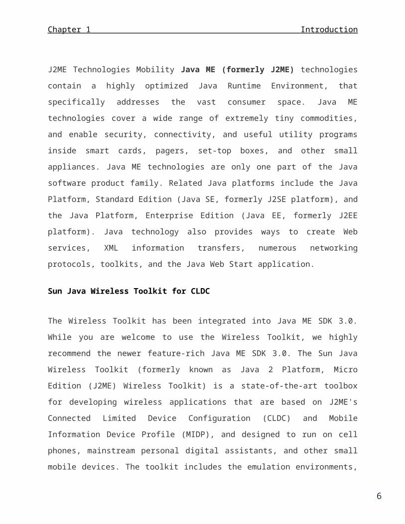
J2ME Technologies Mobility Java ME (formerly J2ME) technologies contain a highly
optimized Java Runtime Environment, that specifically addresses the vast consumer space. Java
ME technologies cover a wide range of extremely tiny commodities, and enable security,
connectivity, and useful utility programs inside smart cards, pagers, set-top boxes, and other
small appliances. Java ME technologies are only one part of the Java software product family.
Related Java platforms include the Java Platform, Standard Edition (Java SE, formerly J2SE
platform), and the Java Platform, Enterprise Edition (Java EE, formerly J2EE platform). Java
technology also provides ways to create Web services, XML information transfers, numerous
networking protocols, toolkits, and the Java Web Start application.
Sun Java Wireless Toolkit for CLDC
5
Chapter 1 Introduction
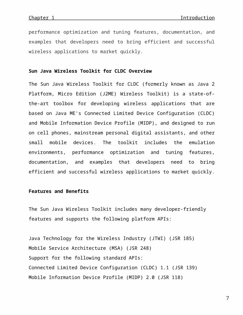
The Wireless Toolkit has been integrated into Java ME SDK 3.0. While you are welcome to use
the Wireless Toolkit, we highly recommend the newer feature-rich Java ME SDK 3.0. The Sun
Java Wireless Toolkit (formerly known as Java 2 Platform, Micro Edition (J2ME) Wireless
Toolkit) is a state-of-the-art toolbox for developing wireless applications that are based on
J2ME's Connected Limited Device Configuration (CLDC) and Mobile Information Device
Profile (MIDP), and designed to run on cell phones, mainstream personal digital assistants, and
other small mobile devices. The toolkit includes the emulation environments, performance
optimization and tuning features, documentation, and examples that developers need to bring
efficient and successful wireless applications to market quickly.
Sun Java Wireless Toolkit for CLDC Overview
The Sun Java Wireless Toolkit for CLDC (formerly known as Java 2 Platform, Micro Edition
(J2ME) Wireless Toolkit) is a state-of-the-art toolbox for developing wireless applications that
are based on Java ME's Connected Limited Device Configuration (CLDC) and Mobile
Information Device Profile (MIDP), and designed to run on cell phones, mainstream personal
digital assistants, and other small mobile devices. The toolkit includes the emulation
environments, performance optimization and tuning features, documentation, and examples that
developers need to bring efficient and successful wireless applications to market quickly.
Features and Benefits
The Sun Java Wireless Toolkit includes many developer-friendly features and supports the
following platform APIs:
Java Technology for the Wireless Industry (JTWI) (JSR 185)
Mobile Service Architecture (MSA) (JSR 248)
Support for the following standard APIs:
Connected Limited Device Configuration (CLDC) 1.1 (JSR 139)
Mobile Information Device Profile (MIDP) 2.0 (JSR 118)
Wireless Messaging API (WMA) 2.0 (JSR 205)
6
Chapter 1 Introduction
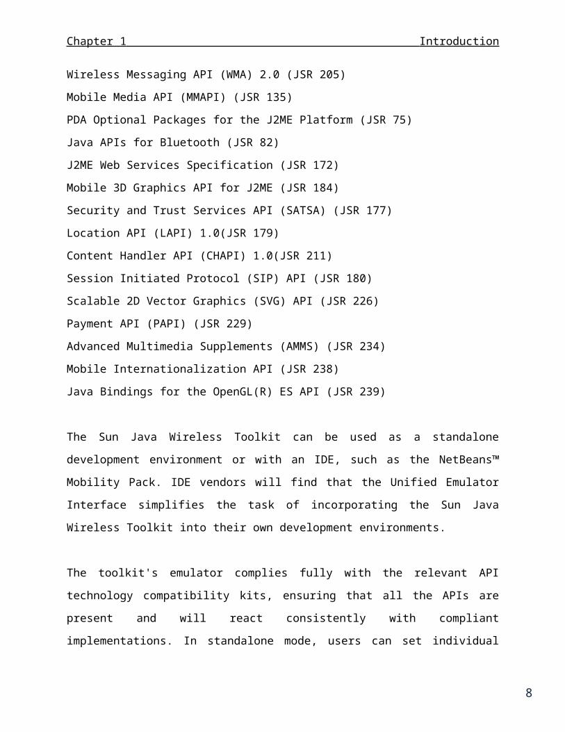
Mobile Media API (MMAPI) (JSR 135)
PDA Optional Packages for the J2ME Platform (JSR 75)
Java APIs for Bluetooth (JSR 82)
J2ME Web Services Specification (JSR 172)
Mobile 3D Graphics API for J2ME (JSR 184)
Security and Trust Services API (SATSA) (JSR 177)
Location API (LAPI) 1.0(JSR 179)
Content Handler API (CHAPI) 1.0(JSR 211)
Session Initiated Protocol (SIP) API (JSR 180)
Scalable 2D Vector Graphics (SVG) API (JSR 226)
Payment API (PAPI) (JSR 229)
Advanced Multimedia Supplements (AMMS) (JSR 234)
Mobile Internationalization API (JSR 238)
Java Bindings for the OpenGL(R) ES API (JSR 239)
The Sun Java Wireless Toolkit can be used as a standalone development environment or with an
IDE, such as the NetBeans™ Mobility Pack. IDE vendors will find that the Unified Emulator
Interface simplifies the task of incorporating the Sun Java Wireless Toolkit into their own
development environments.
The toolkit's emulator complies fully with the relevant API technology compatibility kits,
ensuring that all the APIs are present and will react consistently with compliant implementations.
In standalone mode, users can set individual preferences, build applications, create Java Archive
(JAR) and Java Application Descriptor (JAD) files, and more, using either the toolkit's friendly
KToolbar interface, or its command line. When integrated with an IDE, the toolkit's utilities and
preferences appear in the IDE's menu selections, and also can be controlled from the IDE's
command-line interface. When used with an IDE, the toolkit supports source-level debugging.
7
Chapter 2 Requirement Specifications
Chapter 2: Requirements Specification
1.11 Functional Requirements
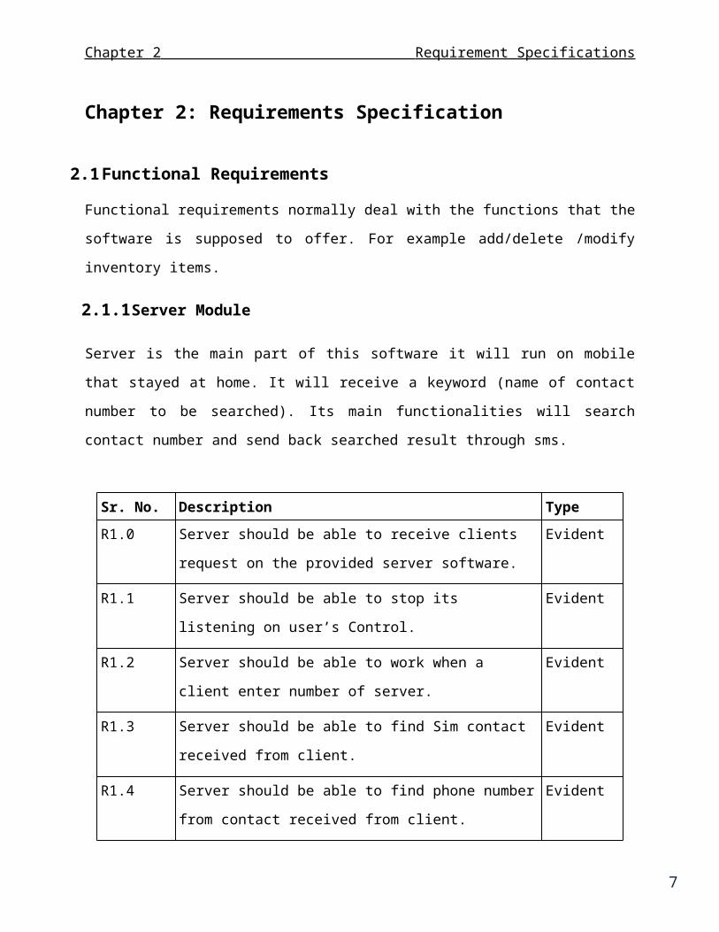
Functional requirements normally deal with the functions that the software is supposed to offer.
For example add/delete /modify inventory items.
1.11.1 Server Module
Server is the main part of this software it will run on mobile that stayed at home. It will receive a
keyword (name of contact number to be searched). Its main functionalities will search contact
number and send back searched result through sms.
Sr. No. Description Type
R1.0 Server should be able to receive clients request on the provided
server software.
Evident
R1.1 Server should be able to stop its listening on user’s Control. Evident
R1.2 Server should be able to work when a client enter number of
server.
Evident
R1.3 Server should be able to find Sim contact received from client. Evident
R1.4 Server should be able to find phone number from contact
received from client.
Evident
R1.5 Server should be able to process messages received from
client.
Evident
R1.6 Server should be able to send Sim contacts to client for restore. Evident
R1.7 Server should be able to return phone contacts to client via
SMS.
Evident
R1.8 If the running server is stopped that it should clear its entire Evident
8
Chapter 2 Requirement Specifications
client list and clean all the text boxes
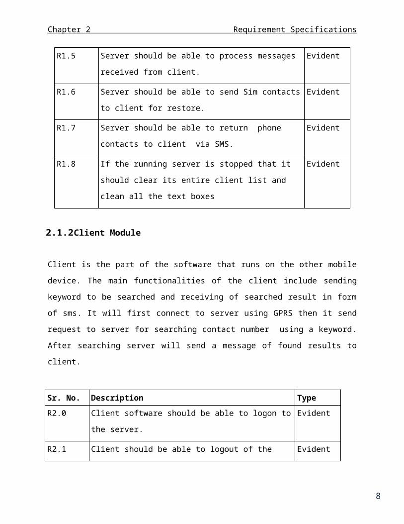
1.11.2 Client Module
Client is the part of the software that runs on the other mobile device. The main functionalities of
the client include sending keyword to be searched and receiving of searched result in form of
sms. It will first connect to server using GPRS then it send request to server for searching contact
number using a keyword. After searching server will send a message of found results to client.
Sr. No. Description Type
R2.0 Client software should be able to logon to the server. Evident
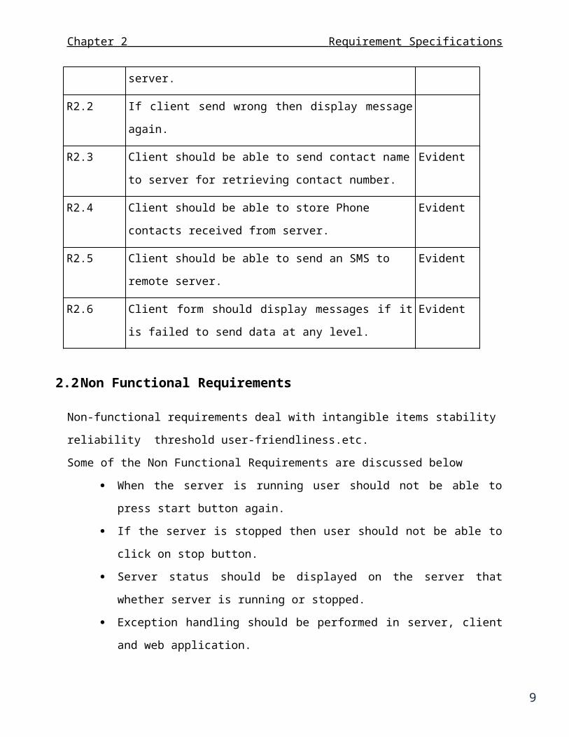
R2.1 Client should be able to logout of the server. Evident
R2.2 If client send wrong then display message again.
R2.3 Client should be able to send contact name to server for
retrieving contact number.
Evident
R2.4 Client should be able to store Phone contacts received from
server.
Evident
R2.5 Client should be able to send an SMS to remote server. Evident
R2.6 Client form should display messages if it is failed to send data
at any level.
Evident
1.12 Non Functional Requirements
Non-functional requirements deal with intangible items stability reliability threshold user-
friendliness.etc.
Some of the Non Functional Requirements are discussed below
When the server is running user should not be able to press start button again.
If the server is stopped then user should not be able to click on stop button.
9
Chapter 2 Requirement Specifications
Server status should be displayed on the server that whether server is running or
stopped.
Exception handling should be performed in server, client and web application.
10
Chapter 3 System Analysis
Chapter 3: System Analysis
1.13 Evaluation of Existing System
Previous systems have no facility to get data from other systems. This simple software has this
facility to get data through GPRS.
1.14 Proposed System
Mobiles are becoming an inevitable part of modern society. People use mobiles to make calls, to
send and read SMS, to store contact information, to store person files, photos, videos and music
etc. Mobiles so became an important storage device with lot of personal and business related
information and messages. The necessity of the information security is increased in this context.
So a mobile contact receiving mechanism is important for the people who mobile remain or
forget at home or any other place.
Proposed system will establish communication over internet. That communication low cost.
Only thing that is spent is power of the mobile device. Now benefits of the proposed system will
be defined in light of above scenarios that were explained in evaluation of existing system.
The objective of this project is to develop a mobile device application which can be used to
receive phone contents from the mobile device to another mobile. Specifically, this application
will enable Sim Contact, phone Contact to find and get from a server mobile, so that if the
mobile device is forget, the user can retrieve their important information.
This project is to allow the user to backup phone contact, Sim contacts, messages, and call
history to a network server. GPRS was chosen as the communication medium between the
mobile device and the server. An application was designed, using Visual Studio 2008, to provide
the user with an interface to execute this operation. A server side system was also developed to
receive the entries and store them in a database. Using this application the phone contents was
transferred from the mobile device and to the server. The extensions to this project included
11
Chapter 3 System Analysis
updating the network server automatically after designing a mechanism to allow this application
to run in the background and connect to server automatically if detect message, incoming call,
missed call, outgoing call.
1.15 Use CasesA use case in software engineering and systems engineering, is a description of steps or actions
between a user and a software system which leads the user towards something useful. Use cases
are a software modeling technique that helps developers determine which features to implement
and how to gracefully resolve errors.
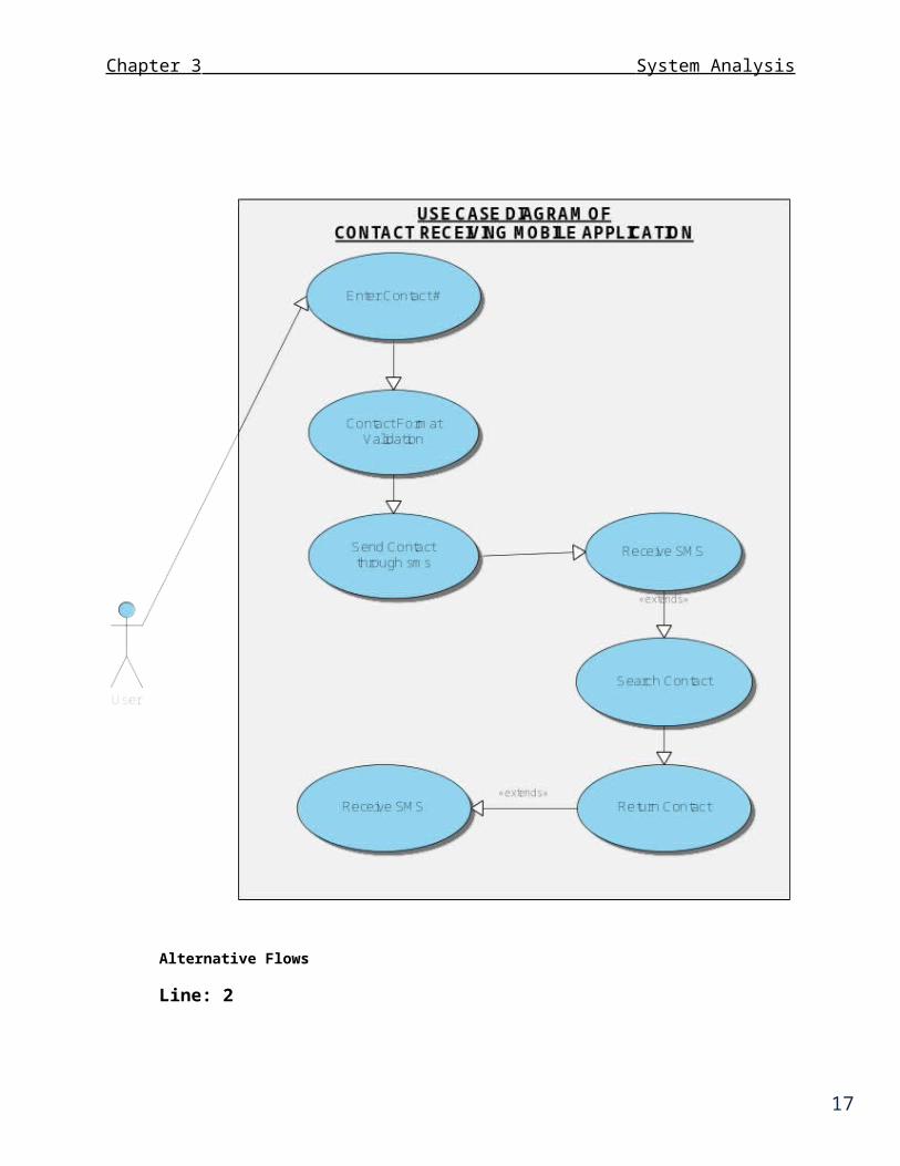
1.15.1 Main Use Case Diagram:
There are two modules in this application .Using client module user will able to access the server
mobile. First user will enter correct number of his/her mobile which was stayed at home or
anywhere. Then enters contact name as keyword whose number user wants to find. Client will
receive searched result through sms.
3.2.2 Use Case Name: Login
Brief Description
This use case begins when End User / Administrator executes the application. The user enters Username and Password to access the application. The System Authenticate, Verify and Authorize the user to access the application.
Use Case: UC1 Startup of System
Actors: Users(user, administrator)
Purpose: For security reason every user required its unique ID and Password.
Overview: The user has to login in order to get access to all features at client level and the admin to get access all the features at client level as well as admin level.
Type: Primary and Essential
12
Chapter 3 System Analysis
Cross References: Requirements: R2.0,R2.1,R2.2
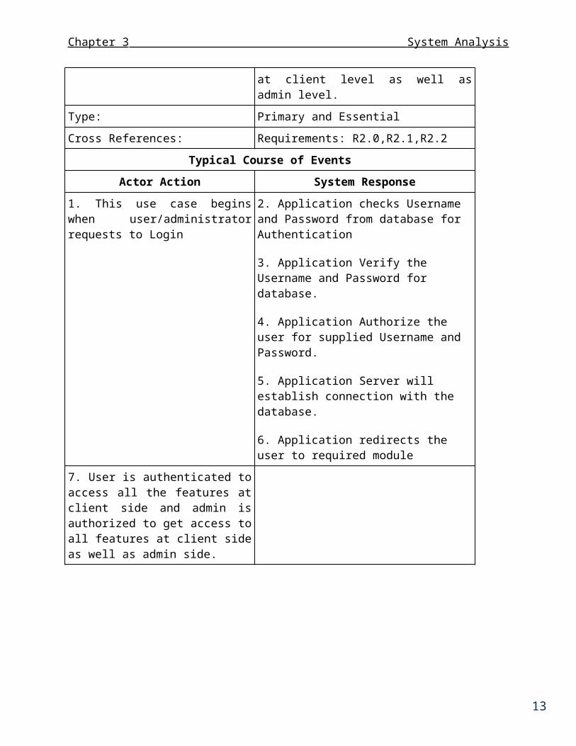
Typical Course of Events
Actor Action System Response
1. This use case begins when user/administrator requests to Login
2. Application checks Username and Password from database for Authentication
3. Application Verify the Username and Password for database.
4. Application Authorize the user for supplied Username and Password.
5. Application Server will establish connection with the database.
6. Application redirects the user to required module
7. User is authenticated to access all the features at client side and admin is authorized to get access to all features at client side as well as admin side.
13
Chapter 3 System Analysis
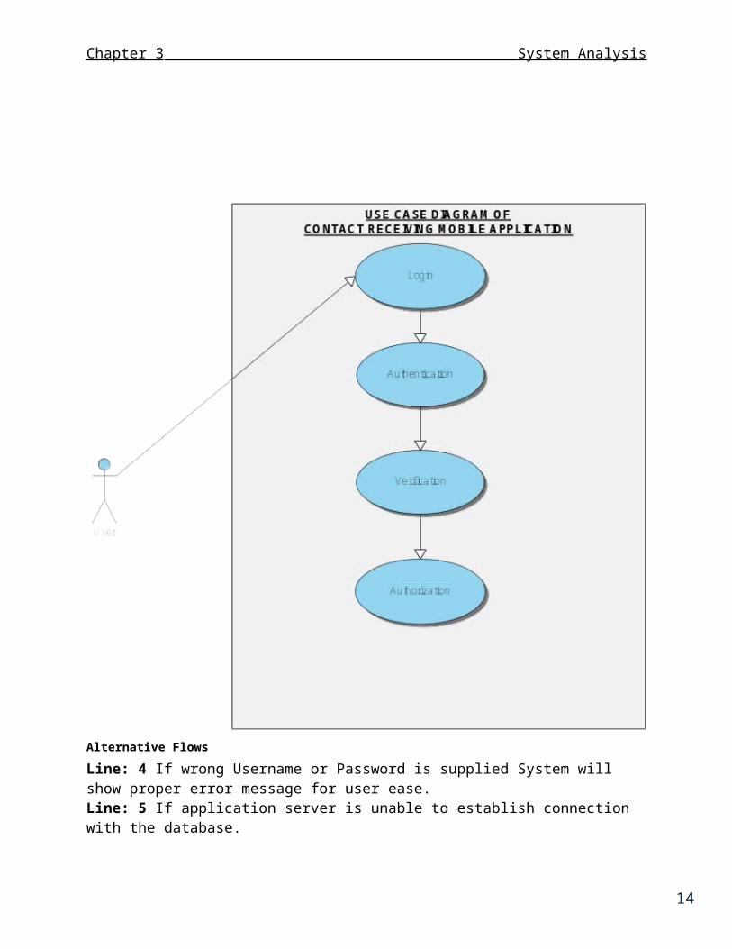
Alternative Flows
Line: 4 If wrong Username or Password is supplied System will show proper error message for user ease.Line: 5 If application server is unable to establish connection with the database.
14
Chapter 3 System Analysis
Pre-Conditions
The user must have a valid id and password.
Post-Conditions
The application must authenticate and authorize the user/administrator.
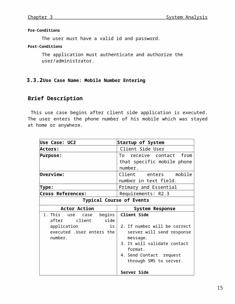
1.15.2 Use Case Name: Mobile Number Entering
Brief Description
This use case begins after client side application is executed. The user enters the phone number of his mobile which was stayed at home or anywhere.
Use Case: UC2 Startup of SystemActors: Client Side UserPurpose: To receive contact from that specific
mobile phone number.Overview: Client enters mobile number in text
field.Type: Primary and EssentialCross References: Requirements: R2.3
Typical Course of Events
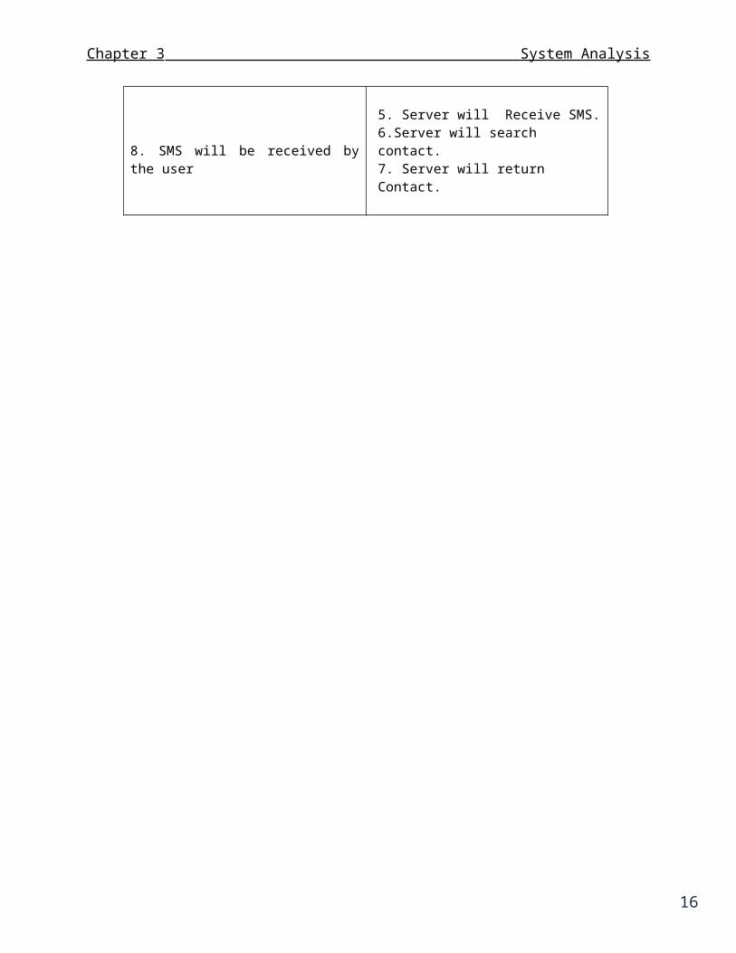
Actor Action System Response1. This use case begins after client side
application is executed .User enters the number.
8. SMS will be received by the user
Client Side
2. If number will be correct server will send response message.
3. It will validate contact format.4. Send Contact request through SMS
to server.
Server Side
5. Server will Receive SMS.6.Server will search contact.7. Server will return Contact.
15
Chapter 3 System Analysis
Alternative Flows
Line: 2
If client enters contact number in wrong format then error message is displayed
appropriately.
16
Chapter 3 System Analysis
Line: 3
If SMS sending failed due to insufficient balance or network failure then a warning
message will be displayed for failure.
Pre-Conditions
The user must have a client side application.
Post-Conditions
If number is correct then server will send response result.
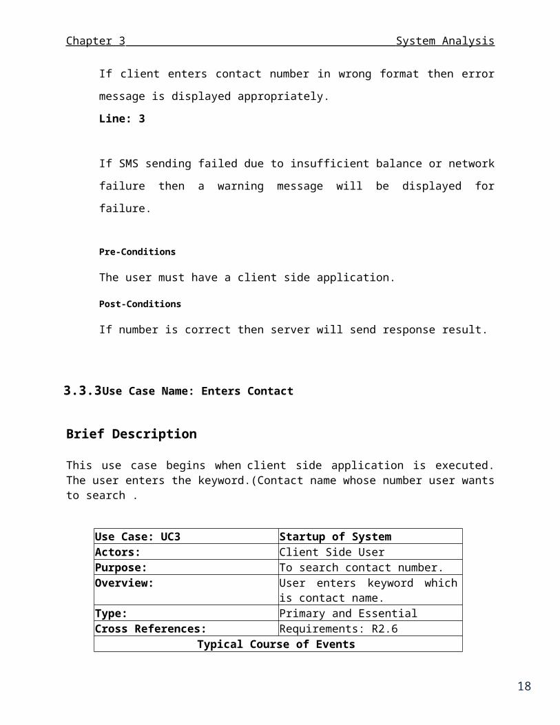
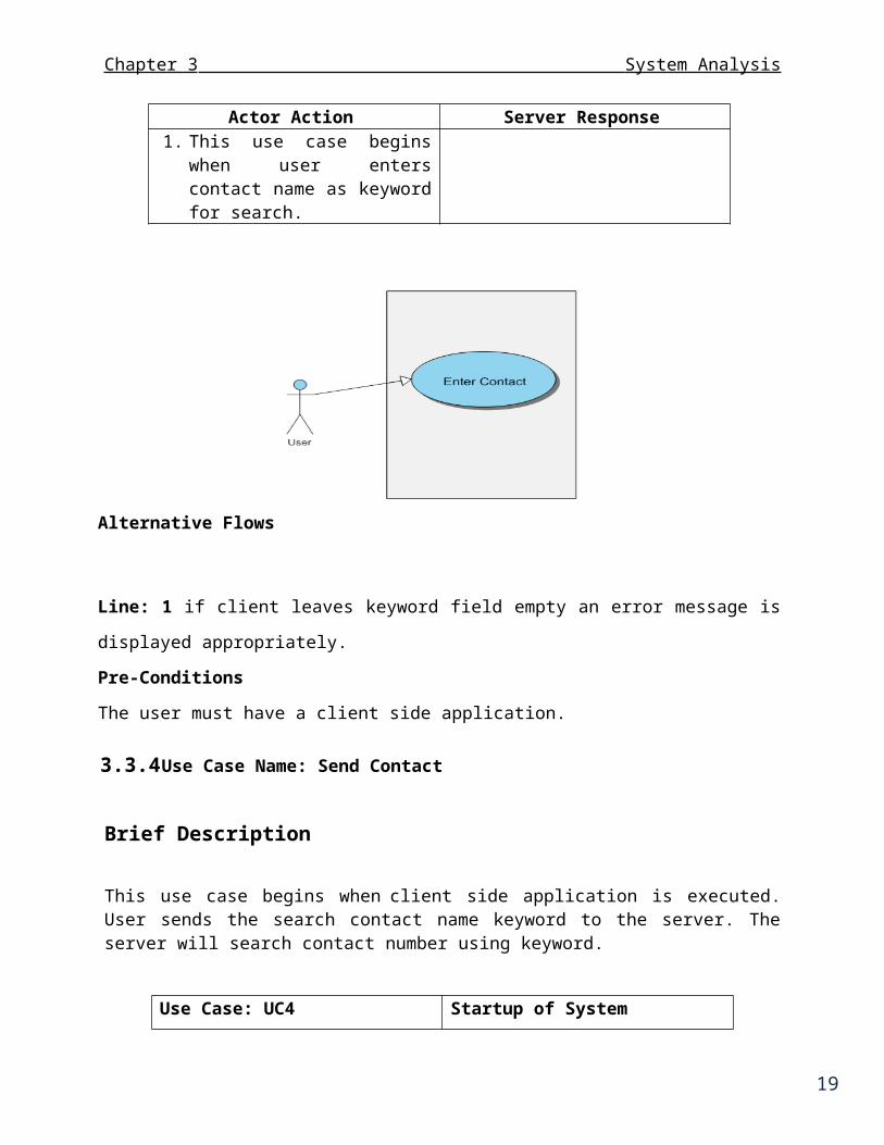
1.15.3 Use Case Name: Enters Contact
Brief Description
This use case begins when client side application is executed. The user enters the keyword.(Contact name whose number user wants to search .
Use Case: UC3 Startup of SystemActors: Client Side UserPurpose: To search contact number.Overview: User enters keyword which is contact
name.Type: Primary and EssentialCross References: Requirements: R2.6
Typical Course of EventsActor Action Server Response
1. This use case begins when user enters contact name as keyword for search.
17
Chapter 3 System Analysis
Alternative Flows
Line: 1 if client leaves keyword field empty an error message is displayed appropriately.
Pre-Conditions
The user must have a client side application.
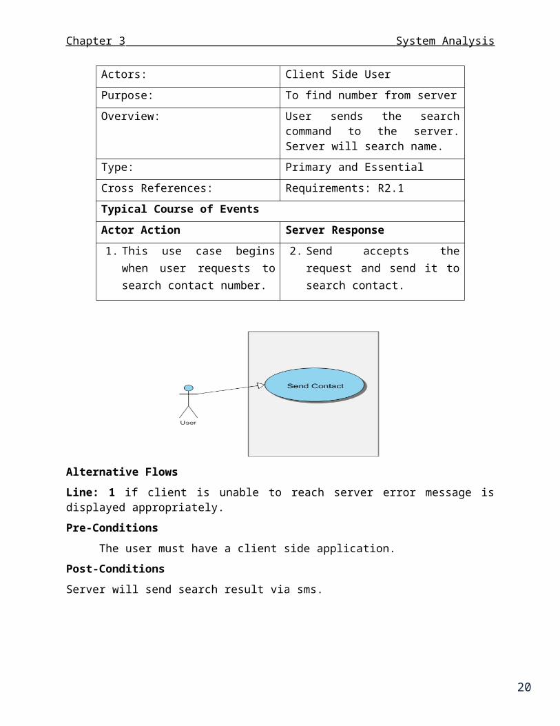
1.15.4 Use Case Name: Send Contact
Brief Description
This use case begins when client side application is executed. User sends the search contact name keyword to the server. The server will search contact number using keyword.
Use Case: UC4 Startup of System
Actors: Client Side User
Purpose: To find number from server
Overview: User sends the search command to the server. Server will search name.
Type: Primary and Essential
Cross References: Requirements: R2.1
Typical Course of Events
Actor Action Server Response
1. This use case begins when user 2. Send accepts the request and send
18
Chapter 3 System Analysis
requests to search contact number. it to search contact.
Alternative Flows
Line: 1 if client is unable to reach server error message is displayed appropriately.
Pre-Conditions
The user must have a client side application.
Post-Conditions
Server will send search result via sms.
21
Chapter 5 System Implementation
Chapter 4: System Design
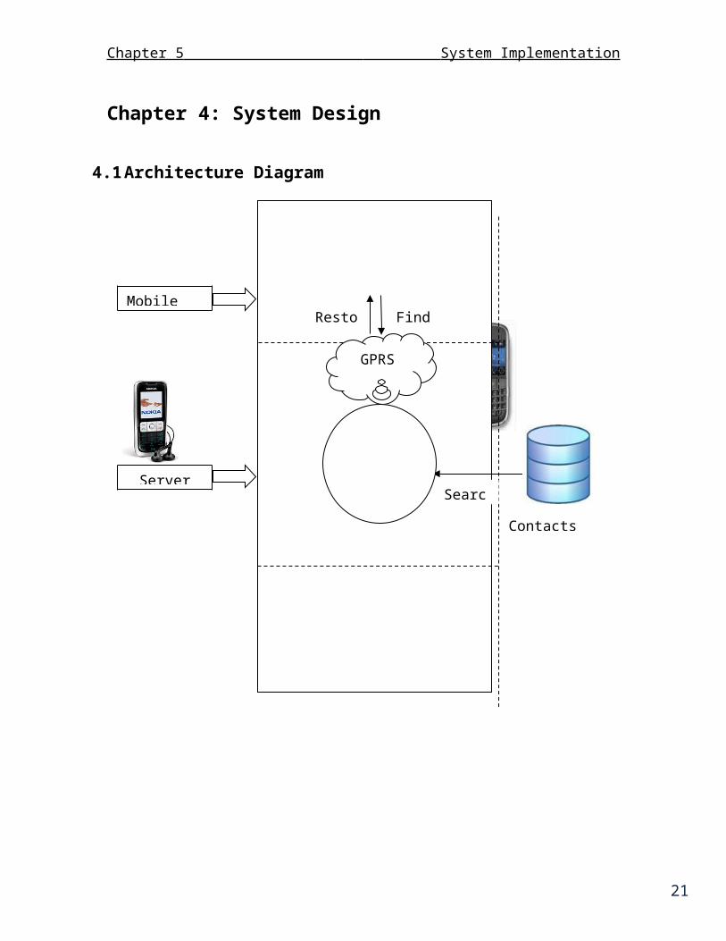
1.16 Architecture Diagram
ServerSearch
Mobile UserFindRestore
GPRS
Contacts
22
Chapter 5 System Implementation
1.16.1 Client Functionality
Client is the part of the software that runs on the mobile device. The main
functionalities of the client include sending and receiving of data to the server
directly. It will connect to server using GPRS then it send request to server for
searching contact number using keyword. It will also send incoming messages,
incoming call, outgoing calls, and dialed number to server.
First client will login to server. It depends on client what they want to do either
find or search. If it sends backup request to server then different type of mobile
contents are saved to server database and if it send restore request to server then
client will get data from server, this data will restore. After doing backup server
will log-off. Server side users include only administrator whose purpose is only to
monitor communication and make sure that everything is working properly.
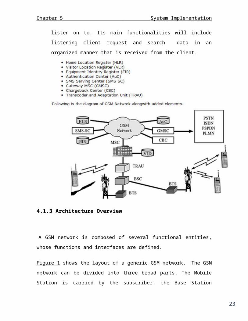
1.16.2 Server Functionality
Server is the second part of this software it will run on a mobile. It will be
provided a phone number to listen on to. Its main functionalities will include
listening client request and search data in an organized manner that is received
from the client.
23
Chapter 5 System Implementation
4.1.3 Architecture Overview
A GSM network is composed of several functional entities, whose functions and
interfaces are defined.
Figure 1 shows the layout of a generic GSM network. The GSM network can be divided
into three broad parts. The Mobile Station is carried by the subscriber, the Base Station
Subsystem controls the radio link with the Mobile Station. The Network Subsystem, the
main part of which is the Mobile services Switching Center, performs the switching of
calls between the mobile and other fixed or mobile network users, as well as management
of mobile services, such as authentication. Not shown is the Operations and
Maintenance center, which oversees the proper operation and setup of the network. The
Mobile Station and the Base Station Subsystem communicate across the Um interface,
24
Chapter 5 System Implementation
also known as the air interface or radio link. The Base Station Subsystem communicates
with the Mobile service Switching Center across the A interface.
Mobile Station
The mobile station (MS) consists of the physical equipment, such as the radio transceiver,
display and digital signal processors, and a smart card called the Subscriber Identity
Module (SIM). The SIM provides personal mobility, so that the user can have access to
all subscribed services irrespective of both the location of the terminal and the use of a
specific terminal. By inserting the SIM card into another GSM cellular phone, the user
is able to receive calls at that phone, make calls from that phone, or receive other
subscribed services.
The mobile equipment is uniquely identified by the International Mobile Equipment
Identity (IMEI). The SIM card contains the International Mobile Subscriber Identity
(IMSI), identifying the subscriber, a secret key for authentication, and other user
information. The IMEI and the IMSI are independent, thereby providing personal
mobility. The SIM card may be protected against unauthorized use by a password or
personal identity number.
Base Station Subsystem
The Base Station Subsystem is composed of two parts, the Base Transceiver Station
(BTS) and the Base Station Controller (BSC). These communicate across the specified
A�bis interface, allowing (as in the rest of the system) operation between components
made by different suppliers.
The Base Transceiver Station houses the radio tranceivers that define a cell and handles
the radio�link protocols with the Mobile Station. In a large urban area, there will
potentially be a large number of BTSs deployed. The requirements for a BTS are
ruggedness, reliability, portability, and minimum cost.
The Base Station Controller manages the radio resources for one or more BTSs. It
handles radio�channel setup, frequency hopping, and handovers, as described below.
25
Chapter 5 System Implementation
The BSC is the connection between the mobile and the Mobile service Switching Center
(MSC). The BSC also translates the 13 kbps voice channel used over the radio link to
the standard 64 kbps channel used by the Public Switched Telephone Network or ISDN.
Network Subsystem
The central component of the Network Subsystem is the Mobile services Switching
Center (MSC). It acts like a normal switching node of the PSTN or ISDN, and in
addition provides all the functionality needed to handle a mobile subscriber, such as
registration, authentication, location updating, handovers, and call routing to a roaming
subscriber. These services are provided in conjuction with several functional entities,
which together form the Network Subsystem. The MSC provides the connection to the
public fixed network (PSTN or ISDN), and signalling between functional entities uses the
ITU�T Signalling System Number 7 (SS7), used in ISDN and widely used in current
public networks.
The Home Location Register (HLR) and Visitor Location Register (VLR), together with
the MSC, provide the call�routing and (possibly international) roaming capabilities of
GSM. The HLR contains all the administrative information of each subscriber registered
in the corresponding GSM network, along with the current location of the mobile. The
current location of the mobile is in the form of a Mobile Station Roaming Number
(MSRN) which is a regular ISDN number used to route a call to the MSC where the
mobile is currently located. There is logically one HLR per GSM network, although it
may be implemented as a distributed database.
The Visitor Location Register contains selected administrative information from the
HLR, necessary for call control and provision of the subscribed services, for each mobile
currently located in the geographical area controlled by the VLR. Although each
functional entity can be implemented as an independent unit, most manufacturers of
switching equipment implement one VLR together with one MSC, so that the
geographical area controlled by the MSC corresponds to that controlled by the VLR,
simplifying the signalling required. Note that the MSC contains no information about
particular mobile stations - this information is stored in the location registers.
26
Chapter 5 System Implementation
The other two registers are used for authentication and security purposes. The
Equipment Identity Register (EIR) is a database that contains a list of all valid mobile
equipment on the network, where each mobile station is identified by its International
Mobile Equipment Identity (IMEI). An IMEI is marked as invalid if it has been reported
stolen or is not type approved. The Authentication Center is a protected database that
stores a copy of the secret key stored in each subscriber's SIM card, which is used for
authentication and ciphering of the radio channel.
Protocol
TCP protocol is used in this communication. The Transmission Control Protocol (TCP) is
one of the core protocols of the Internet Protocol Suite. TCP is one of the two original
components of the suite, complementing the Internet Protocol (IP), and therefore the
entire suite is commonly referred to as TCP/IP. TCP provides reliable, ordered delivery
of a stream of bytes from a program on one computer to another program on another
computer. TCP is the protocol that major Internet applications rely on, applications such
as the World Wide Web, e-mail, and file transfer. Other applications, which do not
require reliable data stream service, may use the User Datagram Protocol (UDP) which
provides a datagram service that emphasizes reduced latency over reliability. TCP
provides a point-to-point channel for applications that require reliable communications.
The Hypertext Transfer Protocol (HTTP), File Transfer Protocol (FTP) and Telnet are all
examples of applications that require a reliable communication channel.
Network function
TCP provides a communication service at an intermediate level between an application
program and the Internet Protocol (IP). That is, when an application program desires to
send a large chunk of data across the Internet using IP, instead of breaking the data into
IP-sized pieces and issuing a series of IP requests, the software can issue a single request
to TCP and let TCP handle the IP details.
IP works by exchanging pieces of information called packets. A packet is a sequence of
octets and consists of a header followed by a body. The header describes the packet's
27
Chapter 5 System Implementation
destination and, optionally, the routers to use for forwarding until it arrives at its
destination. The body contains the data IP is transmitting.
Due to network congestion, traffic load balancing, or other unpredictable network
behavior, IP packets can be lost, duplicated, or delivered out of order. TCP detects these
problems, requests retransmission of lost data, rearranges out-of-order data, and even
helps minimize network congestion to reduce the occurrence of the other problems. Once
the TCP receiver has reassembled the sequence of octets originally transmitted, it passes
them to the application program. Thus, TCP abstracts the application's communication
from the underlying networking details.
TCP is utilized extensively by many of the Internet's most popular applications, including
the World Wide Web (WWW), E-mail, File Transfer Protocol, Secure Shell, peer-to-peer
file sharing, and some streaming media applications.
TCP is optimized for accurate delivery rather than timely delivery, and therefore, TCP
sometimes incurs relatively long delays (in the order of seconds) while waiting for out-
of-order messages or retransmissions of lost messages. It is not particularly suitable for
real-time applications such as Voice over IP. For such applications, protocols like the
Real-time Transport Protocol (RTP) running over the User Datagram Protocol (UDP) are
usually recommended instead.
TCP is a reliable stream delivery service that guarantees delivery of a data stream sent
from one host to another without duplication or losing data. Since packet transfer is not
reliable, a technique known as positive acknowledgment with retransmission is used to
guarantee reliability of packet transfers. This fundamental technique requires the receiver
to respond with an acknowledgment message as it receives the data. The sender keeps a
record of each packet it sends, and waits for acknowledgment before sending the next
packet. The sender also keeps a timer from when the packet was sent, and retransmits a
packet if the timer expires. The timer is needed in case a packet gets lost or corrupted.
TCP consists of a set of rules: for the protocol, that are used with the Internet Protocol,
and for the IP, to send data "in a form of message units" between computers over the
28
Chapter 5 System Implementation
Internet. At the same time that IP takes care of handling the actual delivery of the data,
TCP takes care of keeping track of the individual units of data transmission, called
segments that a message is divided into for efficient routing through the network. For
example, when an HTML file is sent from a Web server, the TCP software layer of that
server divides the sequence of octets of the file into segments and forwards them
individually to the IP software layer (Internet Layer). The Internet Layer encapsulates
each TCP segment into an IP packet by adding a header that includes (among other data)
the destination IP address. Even though every packet has the same destination address,
they can be routed on different paths through the network. When the client program on
the destination computer receives them, the TCP layer (Transport Layer) reassembles the
individual segments and ensures they are correctly ordered and error free as it streams
them to an application.
Reliable transmission
TCP uses a sequence number to identify each byte of data. The sequence number
identifies the order of the bytes sent from each computer so that the data can be
reconstructed in order, regardless of any fragmentation, disordering, or packet loss that
may occur during transmission. For every payload byte transmitted the sequence number
must be incremented. In the first two steps of the 3-way handshake, both computers
exchange an initial sequence number (ISN). This number can be arbitrary, and should in
fact be unpredictable to defend against TCP Sequence Prediction Attacks.
TCP primarily uses a cumulative acknowledgment scheme, where the receiver sends an
acknowledgment signifying that the receiver has received all data preceding the
acknowledged sequence number. Essentially, the first byte in a segment's data field is
assigned a sequence number, which is inserted in the sequence number field, and the
receiver sends an acknowledgment specifying the sequence number of the next byte they
expect to receive. For example, if computer A sends 4 bytes with a sequence number of
100 (conceptually, the four bytes would have a sequence number of 100, 101, 102 and
103 assigned) then the receiver would send back an acknowledgment of 104 since that is
the next byte it expects to receive in the next packet.
29
Chapter 5 System Implementation
TCP ports
TCP uses the notion of port numbers to identify sending and receiving application end-
points on a host, or Internet sockets. Each side of a TCP connection has an associated 16-
bit unsigned port number (0-65535) reserved by the sending or receiving application.
Arriving TCP data packets are identified as belonging to a specific TCP connection by its
sockets, that is, the combination of source host address, source port, destination host
address, and destination port. This means that a server computer can provide several
clients with several services simultaneously, as long as a client takes care of initiating any
simultaneous connections to one destination port from different source ports.
Port numbers are categorized into three basic categories: well-known, registered, and
dynamic/private. The well-known ports are assigned by the Internet Assigned Numbers
Authority (IANA) and are typically used by system-level or root processes. Well-known
applications running as servers and passively listening for connections typically use these
ports. Some examples include: FTP (21), SSH (22), TELNET (23), SMTP (25) and
HTTP (80). Registered ports are typically used by end user applications as ephemeral
source ports when contacting servers, but they can also identify named services that have
been registered by a third party. Dynamic/private ports can also be used by end user
applications, but are less commonly so. Dynamic/private ports do not contain any
meaning outside of any particular TCP connection.
30
Chapter 5 System Implementation
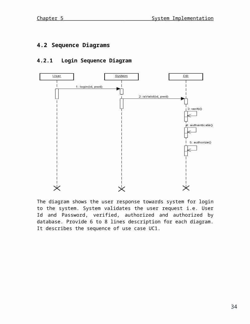
4.2 Sequence Diagrams
4.2.1 Login Sequence Diagram
The diagram shows the user response towards system for login to the system. System validates the user request i.e. User Id and Password, verified, authorized and authorized by database. Provide 6 to 8 lines description for each diagram. It describes the sequence of use case UC1.
31
Chapter 5 System Implementation
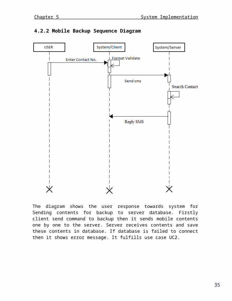
4.2.2 Mobile Backup Sequence Diagram
The diagram shows the user response towards system for Sending contents for backup to server database. Firstly client send command to backup then it sends mobile contents one by one to the server. Server receives contents and save these contents in database. If database is failed to connect then it shows error message. It fulfills use case UC2.
32
Chapter 5 System Implementation
4.3 Class Diagrams
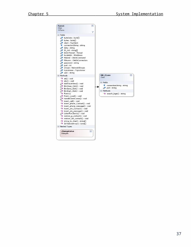
4.3.1Server Side
Form1 is the main class of server. The main functionality of form 1 class is to listen for
clients request and accept their requests and process them accordingly. In these requests
are the login requests, backup, restore request and logout requests.
Server Side
33
Chapter 5 System Implementation
Client Side
34
Chapter 5 System Implementation
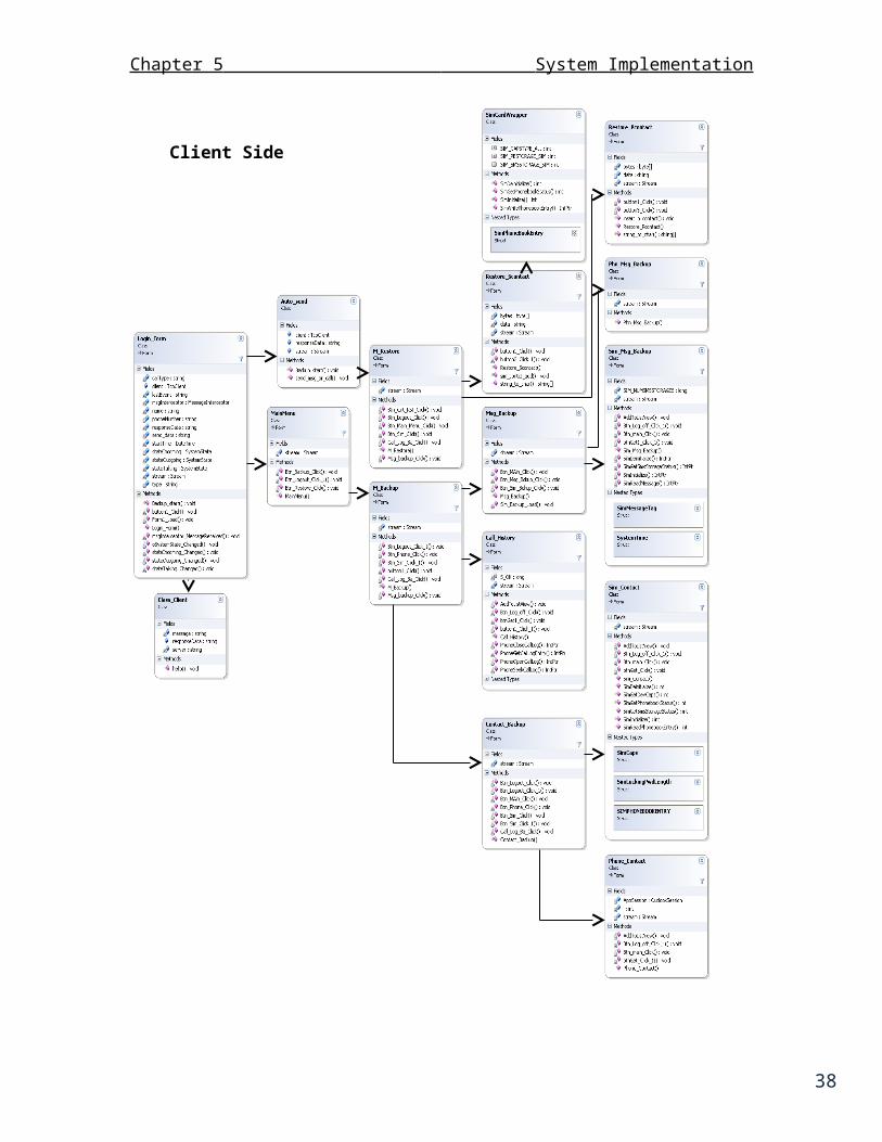
4.3.2Client Side
Login_Form:
Login_form is the main class of Client. The main functionality of login form class is to transmit login and password to the server. If client send wrong user and password it shows error message to retype login detail.
Class Client:
Data is the class that is basically used for data conversion all the received data is given to this class it converts that data from byte form to required form mostly in UTF8. It also converts the data which is to be transmitted into byte form.
Main_Menu:
This class is used to selection option for backup or restore. If we choose backup option we can save our contents to save location and if we select restore option then we can save data in mobile .
Send_Phone_Contact_Name:
This class is used to retrieve phone contact. All available phone contact in mobile list will be searched.
Contact_Retrieval:
This class is used to get contact.
35
Chapter 5 System Implementation
Chapter 5: System Implementation
1.17 Development Objectives Achieved
1.17.1 Server Side Server should be able to receive clients request on the provided
server software.
Server should be able to stop its listening on user’s Control.
Server should be able to work when a client enter number of
server.
Server should be able to find Sim contact received from client.
Server should be able to find phone number from contact received
from client.
Server should be able to process messages received from client.
Server should be able to send Sim contacts to client for restore.
Server should be able to return phone contacts to client via SMS.
If the running server is stopped that it should clear its entire client list and clean all the text boxes
1.17.2 Client Side Client software should be able to logon to the server.
Client should be able to logout of the server.
If client send wrong then display message again.
Client should be able to send contact name to server for retrieving
contact number.
Client should be able to store Phone contacts received from
server.
Client should be able to send an SMS to remote server.
Client form should display messages if it is failed to send data at any level.
36
Chapter 5 System Implementation
1.18 Development Track
Project idea was adopted from the projects which create a simple application using a
server and client over mobile and mobile to communicate with each other . Project
supervisors encouraged the idea and improve it with enhancement. Firstly work in Visual
studio.net 2008 and the project at the start is to get sms when my mobile remain at home
or forget at home.So that need of a default port that get sms and send it to other mobile.
So that for this purpose shifting of project to python because visual stdio donot have any
default port and require wire. In python sms are read but its code is not compatible with
visual studio.net 2008 and J2me.So project supervisor change the project and convert it
in to simple contact read. Contacts are read in J2ME and J2me also have default port for
sms.
Many times there were failures that we have to suffer but after every failure we learnt
something new and immediately radicalize our motivation towards the accomplishment
of our project. Since day one to the day it ends, put a grueling struggle behind every
detail in this project. Research was enormous throughout this time and spent a lot time in
searching for the right way, right technologies to use, so that our project fulfill the idea on
which it is based.
1.19 Development and Build Environment
1.19.1 Hardware Requirements
GPRS connectivity Cellular devices
1.19.2 Software Requirements
JDK 1.6 Netbeans 6.9
37
Chapter 5 System Implementation
1.20 Overall Deployment StrategyWhen it comes to deploy the project we have managed following hardware and software
requirements describe as under each heading respectively.
1.20.1 Hardware Requirements
GPRS connectivity Cellular devices
1.20.2 Software Requirements
Java Virtual Machine
1.21 Screen Shots
1.21.1 Server
This is the graphical user interface (GUI) of the server. Through this interface user
controls the actions of the server. When RUN button is pressed by the user the server
becomes active and starts to listen on a port for TCP packets. When user presses STOP
button the server stops running. The label Server Status shows the current state of the
server. That is it running or has it stopped. The IP address textbox shows the current IP
Address on which the server is available and the Port textbox shows the current port on
which the server is listening to. Server contain multi lined text box which keeps track of
the clients that have logged on to the server. And which are currently online and shows
which client has logged off. It gives overall situation that how many clients are trying to
communicate with it and how many have left or joined. It will display overall status of
client when they connect to server and do some activity. The Connected client list text
box shows all the clients that are currently logged on the server. When a client logs on the
server the name of the client is added to the textbox. When client logs off the server the
name of the client is removed from the text box. And it fulfill usecase UC1, UC2.
38
Chapter 5 System Implementation
1.21.2 Client Login Page
When user presses this button after entering user name and password, application will try to connect to server. The client application need user and password to connect to the server. If user enter wrong user and password , application shows error message. It fulfills requirements of usecase UC1.The Login Screen custom component provides a useful user interface with standard elements such as Username Field, Password Field and Login Button. You can use this custom component to create the login interface.
1.21.3 Remote Contact Recieving
Emter Username
Enter Password
39
Chapter 5 System Implementation
The SMS Composer is a custom component that provides a mechanism and user interface
to send contact name via short message using Short Message Service (SMS). This
component utilizes the JSR-120 Wireless Messaging API. This API is not a part of the
MIDP 2.0 specification so this custom component can only be deployed to devices that
have built-in support for JSR-120. When user presses this button after entering server
number and contact name, application will try to connect to search the contact. If user
enter wrong number or contact name , application shows error message. It fulfills
requirements of use case UC2.
Contact Name to Search
40
Chapter 5 System Implementation
Contact Receive here
41
Chapter 5 System Implementation
When user presses this button after entering server number and contact name, application
will try to connect to server and search contact. If user enter wrong number or contact
name, application shows error message otherwise it will fulfill usecase UC4.
21
Chapter 6 System Testing
Chapter 6: System Testing
1.22 Test Cases
1.22.1 Test Case Name: Login
Test Case ID
TC-1Reference number
QA Test Engineer Name of personnel
Test case Version: 1 Shagufta Yaseen Shagufta Yaseen
Test Date: 01-Jul-11 Use Case Reference(s) UC1
Revision History None
Objective To test that Client login to server, server enlists the client in login list after checking login from file. If login record is available then send connected message to client application to start communication.
Environment: System must be in running condition
Assumptions: Corrupt Application software Hardware crashes
Pre-Requisite: System must be running properlyLogin form is opened User,Password is entered properly
Step #Execution description Procedure result
1.2.3.
4.
Data with Empty fields are testedUser requests login.Server receives Login request.
Clients receive login message from server.
Required fields must be filled.Server Checks database for this login and if is exists, send connected message to client and send error if login is not valid.GPRS must be activated.
CommentsThe login scenario is tested when server is running , if failed to connect it gives error message
Passed[√] Failed[] Not Executed[]
22
Chapter 6 System Testing
1.22.2 Test Case Name: Send Contact Name
Test Case ID
TC-2Reference number
QA Test Engineer Name of personnel
Test case Version: 1 Shagufta Yaseen Shagufta Yaseen
Test Date: 01-Jul-11 Use Case Reference(s) UC1,UC2
Revision History None
Objective To test that client sends different contact names to the server successfully. Server receives that contacts and search in contact list of cell phone.
Environment: System must be in running condition
Assumptions: Corrupt Application software Hardware crashes
Pre-Requisite: System must be running properlyClient is logged in the server
Step #Execution description Procedure result
1.2.
User requests for sending contact name. Server must be in running condition so different contacts sending frequently to the server.GPRS must be activated.
CommentsThis scenario is tested when client sends contact name.
Passed[√] Failed[] Not Executed[]
1.22.3 Test Case Name: Receive Contact Details
Test Case ID
TC-3Reference number
QA Test Engineer Name of personnel
Test case Version: 1 Shagufta Yaseen Shagufta Yaseen
23
Chapter 6 System Testing
Test Date: 01-Jul-11 Use Case Reference(s) UC1,UC2,UC3
Revision History None
Objective To test that client sends Restore request to server. Server receive client request and then search the contact list. If found any record then send it back to user. Client receives this record via SMS.
Environment: System must be in running condition
Assumptions: Corrupt Application software Hardware crashes
Pre-Requisite: System must be running properlyClient is logged in the server
Step #Execution description Procedure result
1.2.3.
4.
User requests for sending contact name.Server Check its database and send it to client.
Clients receive contact detail from server and can save it in phone.
Server must be in running condition so different contents sending frequently to the server.GPRS must be activated.
CommentsRestore scenario is tested when client sends request to server. Server receive client request and then search the database. If found any record then send it one by one. Client receives this record and save it in the phone.
Passed[√] Failed[] Not Executed[]
24
Chapter 6 System Testing
1.22.4 Test Case Name: Logout
Test Case ID
TC-4Reference number
QA Test Engineer Name of personnel
Test case Version: 1 Shagufta Yaseen Shagufta Yaseen
Test Date: 01-Jul-11 Use Case Reference(s) UC1
Revision History None
Objective To test that Client logs out of the server, server removes enlisted client. Client closes its sockets for no more connection to server.
Environment: System must be in running condition
Assumptions: Corrupt Application software Hardware crashes
Pre-Requisite: System must be running properlyClient must be logged in the server
Step #Execution description Procedure result
1.2.3.
4.
User requests logout.Server receives Logout request.
Clients closed.
User is logged out of the server.Server removes enlisted user from login list. GPRS must be activated.
CommentsThe logout scenario is tested when server is in range and client requests logout, if server is out of range than client will try to send its message through its neighbors. If no neighbor is in range than it will display an error message.
Passed[√] Failed[] Not Executed[]


