Consumers of Alternating Current 230 v No Interruption
13
2.3. EQUIPMENT USING NON-INTERRUPTION-FREE 230V ALTERNATING CURRENT It can be found all those installation elements in this device that, due to its way of working, allow interruptions in the current supply without affecting its functioning. The se equipments rece ive the sup ply from the swi tching closet, the sup ply bei ng previ ousl y filtered and stabi lized. The equip ments are fed from the tens ion comin g from overhead power cable, if this is present, and they are fed from network 2, when there is a failure in the network 1. The equipments that are inside this device are: • Air-conditionings • Inside lights of buildings. • Outside lights of buildings. • Electrical installation of distribution in buildings. • Water pump. • System of sanitary hot water. 2.4. EQUIPMENT USING INTERRUPTION-FREE 40 0V AL TERNAT ING CURRENT The starting engines of the needles are fed with a 400-V three-phase tension between phases (230 V between phase and neutral. Since the main source of supply – Network 1 – is single-phased it is necessary to install a static single-phase/three-phase converter. If the mentioned converter fails, it is necessary to install an automatic electromagnetic switching that feeds activations from network 2, in those buildings in which the it is supplied from the public network, or it starts the emergency generator in those buildings where it is installed. 2. 5. EQUIPMENT USI NG DIRECT CURRENT It is necessary to have an alternating current supply for the functioning of the signaling equip ments / telecommunicat ion. This is supp lied by a rectifi er / servic e charger and some stati onary batt eries free of maintena nce with 60 minutes auto nomy . A second rec ti fi er / emergency char ger is added in or de r to gr ant the functi oning of the installation, which starts working when there is a rectifier / service charger failure. 2.6.SUPPLYING POWER TO IN-TRACK EQUIPMENT For the supply of the signaling equipments and telecommunication installed on rails, two armed cables will be laid from each technical building towards north and south to an average point? of each stretch under its influence. These cables will be of the right section to the charge and length of the stretch, so that the supply within the margins of each equipment is guaranteed. The cables of every stretch will en in a technical hut or in a line closet. Energy cables from the two collateral technical buildings will go to the technical hut or line closet, and the installation of the adequate equipment that allow to supply the whole part from one technical building in case of damage or short circuit of any of the two cables will be planned. For the supply of the equipments the cable should go in and out of these without making T derivations in the gutter. This will allow, if it is necessary, to cut off the cable to find short circuits. The equipments installed on rails should have a transformer which reduces 750 / 230 V of the adequate power and should be protected with the corresponding fuses, thermal-magnetic switches and protection elements against high tension. In the same way they should have the terminals of adequate section that allow the supply cable to be series connected.
Transcript of Consumers of Alternating Current 230 v No Interruption

8/4/2019 Consumers of Alternating Current 230 v No Interruption
http://slidepdf.com/reader/full/consumers-of-alternating-current-230-v-no-interruption 1/13
2.3. EQUIPMENT USING NON-INTERRUPTION-FREE 230VALTERNATING CURRENT
It can be found all those installation elements in this device that, due to its way of
working, allow interruptions in the current supply without affecting its functioning.
These equipments receive the supply from the switching closet, the supply being previously filtered and stabilized. The equipments are fed from the tension coming
from overhead power cable, if this is present, and they are fed from network 2, when
there is a failure in the network 1. The equipments that are inside this device are:
• Air-conditionings
• Inside lights of buildings.
• Outside lights of buildings.
• Electrical installation of distribution in buildings.
• Water pump.
• System of sanitary hot water.
2.4. EQUIPMENT USING INTERRUPTION-FREE 400V ALTERNATINGCURRENT
The starting engines of the needles are fed with a 400-V three-phase tension between
phases (230 V between phase and neutral. Since the main source of supply – Network 1
– is single-phased it is necessary to install a static single-phase/three-phase converter. If
the mentioned converter fails, it is necessary to install an automatic electromagnetic
switching that feeds activations from network 2, in those buildings in which the it is
supplied from the public network, or it starts the emergency generator in those buildings
where it is installed.
2.5. EQUIPMENT USING DIRECT CURRENT
It is necessary to have an alternating current supply for the functioning of the signaling
equipments / telecommunication. This is supplied by a rectifier / service charger and
some stationary batteries free of maintenance with 60 minutes autonomy. A second
rectifier / emergency charger is added in order to grant the functioning of the
installation, which starts working when there is a rectifier / service charger failure.
2.6.SUPPLYING POWER TO IN-TRACK EQUIPMENT
For the supply of the signaling equipments and telecommunication installed on rails,
two armed cables will be laid from each technical building towards north and south to
an average point? of each stretch under its influence. These cables will be of the rightsection to the charge and length of the stretch, so that the supply within the margins of
each equipment is guaranteed. The cables of every stretch will en in a technical hut or in
a line closet. Energy cables from the two collateral technical buildings will go to the
technical hut or line closet, and the installation of the adequate equipment that allow to
supply the whole part from one technical building in case of damage or short circuit of
any of the two cables will be planned. For the supply of the equipments the cable should
go in and out of these without making T derivations in the gutter. This will allow, if it is
necessary, to cut off the cable to find short circuits. The equipments installed on rails
should have a transformer which reduces 750 / 230 V of the adequate power and should
be protected with the corresponding fuses, thermal-magnetic switches and protectionelements against high tension. In the same way they should have the terminals of
adequate section that allow the supply cable to be series connected.
8/4/2019 Consumers of Alternating Current 230 v No Interruption
http://slidepdf.com/reader/full/consumers-of-alternating-current-230-v-no-interruption 2/13
2.7.SUPPLYING POWER TO MISCELLANEOUS RAILWAYINFRASTRUCTURE /TECHNICAL HUTS SUPPLY
The technical huts will have double supply. They will be supplied with 750 V tension
provided by the supply cable which is the main source, and they will also be supplied
from the overhead power cable tension, through a transformer in a post, as emergency
source.
Those consumers which are not signaling or telecommunications ones, such as air-
conditionings, lighting, etc, will be supplied with the overhead power cable tension.
An overhead power cable filter, a stabilizer, a transformer which reduces 750 / 230 V
ac, network automatic switching, static IAS with incorporated static by-pass and
batteries free of maintenance for a full charge autonomy of 15 minutes and insulation
transformers will be installed, for the equipments supply:
• Audio-frequency rail circuits.
• Routes counters. ?
• Signs.
• ERTMS markers.• Transmission system.
• Temperature control.
• Intrusion detection system.
• Fire detection system.
• Emergency lighting.
Two huts and only a tower will be installed in the GSM-R locations. One of the huts
will be for GSM-R, and the other one for public telephone operators. Thus, it will be
necessary to provide an electrical supply to both huts, also the installations, which
without occupying these huts physically, are electrically hanging from them, for
example, boosters and equipment inside the tunnels.
This project aims at resolving this need, as well as providing the necessary protection
elements to the system. Besides, given the redundancy determinants and security the
GSM-R installations require, the network design like a double layer, the double supply
from the overhead power cable and the 750 V ca line that passes through the gutter, it
has been also provided some batteries inside the huts to provide the important
consumers with a functioning backup. In the case of Operator installations, the need to
secure the supply is not so elevated, that is why there is not duplicity in intake supply,
but there are two lines, without the possibility of switching between them. Thus, given
the forecast consumption, the installation of a 10 kVA transformer for GSM-R and of
30 kVA for public telephone operators is necessary. Both transformers are described indetail in the corresponding overhead power cable section.
For both cases, and considering the high consumption produced by air-conditioning
compressors, these will be exclusively supplied by the line/s from the overhead power
cable.
In the GSM-R hut, due to the existence of equipments which consume electricity a –48
Vdc, it will be necessary the installation of an AC/DC rectification closet. Besides, it is
also necessary to provide the system fundamental elements with a supply backup, a
block of batteries and a DC/AC inverter will be also installed, for the consumers in 230
Vac with the need to secure the electrical supply.

8/4/2019 Consumers of Alternating Current 230 v No Interruption
http://slidepdf.com/reader/full/consumers-of-alternating-current-230-v-no-interruption 3/13
2.8.PROTECTION AGAINST ELECTROCUTION/PEOPLE PROTECTIONAGAINST INDIRECT CONTACTS.
People who work with the electrical equipments described above have to be protected
against accidents caused by indirect contact with any of the tensions present in the
installation.
The inside equipments guarantee people protection against indirect contact through the
earth lead of all the accessible metallic parts of the electrical equipments. Inside the
same room it will be performed a ring connection of all the equipments and, at the same
time, this will be connected to the earth main bar, which is connected to the earth lead
of the electrical building and the earth rail. The security of the earth lead is guaranteed
by periodic inspections in all the connections on behalf of maintenance staff.
The outside equipments will be supplied by insulating transformers that guarantee the
separation of neutral and ground. The insulation between neutral and ground is
constantly supervised by supervisor equipment, which will say when the insulation
decreases up to unacceptable levels. The insulation will be guaranteed by regular
inspections of the supervisor equipment and the measured insulation, on behalf of themaintenance staff.
3 REMOTE ENERGY CONTROL
3.1. INTRODUCTION
This summary comprises the following sections:
A. Brief description
A.1. Control Center configuration
A.2. Software central controlA.3. Front-End Sub-system
A.4. Interfaces
3.2. Brief description
The proposed solution includes the following main components
Complete solution for CRC control center, consisting of CCO, associated PRO’s, PLO’s
and CM’s including servers, computers, remote terminal units (RTU), and all the
necessary software functions to fulfill the goals of the project.
The proposed Control and Regulation Center (CRC) can be divided in the main
categories:Control and Operation Center (COC)
Operation Regional Post (ORP)
Operation Local Post (OLP)
Maintenance Center (MC)
Substation SS-EE
Substations equipment
To obtain data and send it to the COC
To use control commands
Communications equipmentConnection equipment between COC, ORP, OLP and SS-EE

8/4/2019 Consumers of Alternating Current 230 v No Interruption
http://slidepdf.com/reader/full/consumers-of-alternating-current-230-v-no-interruption 4/13
In Document N° 1 MEMORY AND APPENDIXES, Chapter 1 “Detailed description of
the technical solution proposed” it is explained in which way the solution proposed
corresponds to the functions of the software required by GIF.
3.2.1. Control Center Configuration
SINAUT Spectrum is basic technology proposed by Siemens for the control center.
The system has been totally developed by SIEMENS. SINAUT Spectrum offers a
completely integrated solution based on the use of functional, systematized, checked at
length and error testing software packages.
SINAUT Spectrum has almost four decades of experience in the field of computer
control systems in the industry of energy control. That is why SINAUT Spectrum is
composed by functional, systematized, checked at length and error testing software
packages. Installed in distributed and redundant systems under the UNIX
SINAUT Spectrum platform, and the set of servers and SUN Microsystems work
stations, as well as the SUN Solaris 8 operating system, it offers the most reliable
architecture and availability. The modular and distributed architecture of the SINAUTSpectrum offers unlimited opportunities of horizontal and vertical expansion.
SINAUT Spectrum has been carefully designed according to recognized standards and
norms of the industry. Since the system is mainly based on such norms it avoids, where
possible, the use of exclusive methods, allowing a modular updating and taking
advantage of the constant development of new technologies in computers and servers.
Such updating can be installed without damaging the initial and constant investment of
the software throughout of time.
In this way, SINAUT Spectrum provides a solution which can be updated constantly
(“Evergreen” concept) preserving and protecting the GIF investment at the software and
hardware level SINAUT Spectrum uses the commercial server RDBMS (Oracle) with
SQL access according to the standard norms for storing source data. SINAUT Spectrum
is based on the operating system UNIX in compliance with IEEE POSIX norms.
The SINAUT Spectrum configuration proposed represents the last development in
SCADA/EMS technology in the constant development of SINAUT Spectrum. This
advanced designed offers the greatest degree of reliability and operating capacity. The
architecture of the platform is completely adjusted to the requirements of the
specifications, according to the international norms that allow future extensions and
updating of the system in a simple way.
The outstanding characteristics of the system proposed based on SINAUT Spectrum are
described below:
Database administration system of simple use, facilitating on line interaction, data
modification and display editing in a simple way, without interfering with the
functioning of the energy supply system – having no previous knowledge of the
software
Open system architecture based on the strictest compliance of international norms
Hardware and software distributed configuration providing the best performance due
to parallel processing that allows selectable redundancy and simplified expansion

8/4/2019 Consumers of Alternating Current 230 v No Interruption
http://slidepdf.com/reader/full/consumers-of-alternating-current-230-v-no-interruption 5/13
Work stations and servers installed in UNIX of SUN Microsystems Inc. the main
and most reliable computer provider, with a wide range of products, including 64 bits
processors and multiprocessors
UNIX user interface based on X11 standards
Modern process interface for remote terminal units connections (RTU) using
international communication norms
Powerful link with control center exclusively based on IEC standards
Servers and computers updating according to the latest technology and/or new
versions updating through simple merge procedures
Full color displayed graphics in 18” high resolution monitors with zoom, echo-
suppression, panning
ORACLE® based file providing the maximum possible access to data from other IT
environments (i.e. offices)
Data administration system in ORACLE® to on line access and administration
display
High performance communication real-time application program (SOFTBUS)
Modular, structured, systematized and validated application software with
interfaces clearly defined for easy maintenance and improvements
The configuration proposed uses standard solutions, where possible, having the
following advantages:
More foreseeable implementation period
Greatest degree of reliability and system accessibility
Possibility of implementing new updating and improvements through a simple merger
procedure, which guarantees the addition of the latest software version, without the loss
of existing data in previous versions
Ease for future extensions of the SCADA applications, for example new or modified
market rules
Use of on line teleservice support for specialists’ remote support during the
implementation, guarantee, and future maintenance phases
Access to the experience obtained in similar projects
Effective and immediate acquisition of Siemens and SUN technology spare parts

8/4/2019 Consumers of Alternating Current 230 v No Interruption
http://slidepdf.com/reader/full/consumers-of-alternating-current-230-v-no-interruption 6/13
Figures N° 1, 2 and 3 show a general view of the control center configuration, it is also
shown the main subsystems which are part of the architecture of the system:
(Page 86) Figure N° 1 OCC system configuration-BAR: Real-Time
NETWORK ESQUEMATIC ARCHITECTURE IN OOC REAL-TIME (left to right)
2x4 backward projection Control PEOS Terminal Server
VPS Lan
GIF Fixed WAN Communications
Switch
Operation 1
Operation 2
Laser printer
Color-printing machine
Spectrum LAN 1
Router
LAN (10/100 Mbps Switch)Switch
GPS System
Administration Server
Operating and Communication 1 Server / 2-RTC
InterCommunication Server IC CP 2
Administration Position 1 and 2
Router
Remote Link to CRC
CCO-ZAR
Mirror Disk Array
Integration and History 1/2 Server
REMOTE CONTROL SYSTEM – “PUIGVERD DE LLEIDA- BARCELONA”
IN MADRID HIGH SPEED LINE – BARCELONA – FRENCH BORDER
7.2.1.1. Real-time Operation and Control Center (OCC)
The OCC is the core of SCADA system. This includes:
2 x ADM servers (Sun Blade2000)This server has the main software and the source database as well as the data
engineering tools (Source data administration, ADO) and SIH file.
One of the servers provides redundancy to the other server. A RAID system is used to
keep data in a redundant way and to quickly access to both servers.
This server is located in the CRC installations facilitating synchronicity with current or
future control centers that can be integrated under the MULTISITE concept provided
by SINAUT Spectrum. One of the global solutions that covers the complete network of
CCO-MAD/ CCO-BAR y CCO-ZAR system is shown in Figure N° 4.
A greater description of the MULTISITE concept is presented at length in Chapter 4
“Technical Instructions”.
2 x ADM servers (Sun Blade2000)
8/4/2019 Consumers of Alternating Current 230 v No Interruption
http://slidepdf.com/reader/full/consumers-of-alternating-current-230-v-no-interruption 7/13
This server has identical software and provides data redundancy to the CRC one. One of
the servers provides redundancy to the other server.
2 x Real-Time Communication Servers (RTC 1/2) (Sun Blade2000)
This server executes the real-time data processing (SCADA programs). One of the
servers provides redundancy to the other server in “hot-standby” mode.
2 x Server ICCP 1 & 2 (Sun Blade 150)
This server executes the communication protocol ICCP. This allows communication
with other control centers (OCC Zaragoza and OCC Downtown Zone) to data
acquisition at these centers. One of the servers provides redundancy to the other server.
2 x Computers with 4 monitors (Sun Blade 150)
Operation servers for SCADA system.
2 x Administration Posts (Personal Computers)
The operator uses the personal computer (PC) for administrative, learning andsimulation tasks. The operator uses the computer as a user interface of the simulation
system, which runs its activities on the OTS2 server (Operator Training Simulator).
7.2.1.2. Quasi-Real-Time Operating and Control Center (OCC)The Quasi-Real-Time Operating and Control Center (OCC) has:
1 x Server OTS2 (ADM/SDM/RTC) with 2 monitors (Sun Blade2000)
This server has the main software (ADM) and the source database as well as the data
engineering tools (ADO). It is also run the real-time data processing (RTC) with event
simulation capacity. This server also runs the learning functions used to prepare,supervise and assess the learning sessions.
The server has two monitors so in that way the trainer can prepare and supervise the
learning sessions.
2 learning computers with 4 monitors (Sun Blade 150)
This server runs the power supply system simulator software (PSS) that provides
“measured values” to the other server (ADM/SDM/RTC) which simulates the control
center software.
1 administration post (Personal Computers - PC)
The operator uses a personal computer (PC) for administrative, training and simulation
tasks, which has an OTS2.
Figure N° 2 shows the configuration of simulation and learning system. The structure
which belongs to the LAN network as well as the other elements are presented in the
mentioned figures.
(Page 88) Figure N°2 OCC-BAR Configuration System: Quasi-Real-Time
NETWORK ESQUEMATIC ARCHITECTURE IN OOC QUASI-REAL-TIME (left to
right)
OCC LAN
Data system main server “OTS2”
Quasi-real server “PSS”
PDS LANLaser printer

8/4/2019 Consumers of Alternating Current 230 v No Interruption
http://slidepdf.com/reader/full/consumers-of-alternating-current-230-v-no-interruption 8/13
Administration post
REMOTE CONTROL SYSTEM – “PUIGVERD DE LLEIDA- BARCELONA”
IN MADRID HIGH SPEED LINE – BARCELONA – FRENCH BORDER
7.2.1.3. Operation Regional Posts (ORP)
The operation regional center (ORP) has:
2 x ADM servers (Sun Blade2000)
This server has identical software and provides data redundancy to the Operation and
Control Center (OCC).
One of the servers provides redundancy to the other server.
1 x Computer with 4 monitors (Sun Blade 150)
It allows the SCADA system operation to the regional operator. Figure N° 3 shows the
configuration of the operation regional posts.
(Page 88) Figure N° 3 - ORP System configuration: Operation Regional Posts (ORP)
ESQUEMATIC ARCHITECTURE IN OPERATION REGIONAL POSTS (ORP) (left
to right)
OCC LAN
Operator
ORP LAN
Front-End Servers 1/2
DEMS servers 1/2
RTU
REMOTE CONTROL SYSTEM – “PUIGVERD DE LLEIDA- BARCELONA”
IN MADRID HIGH SPEED LINE – BARCELONA – FRENCH BORDER
7.2.1.4. Maintenance Centers (MC)
The maintenance centers (MC) for SCADA system is located at the OCC.
And they have the following elements:
2 x ADM servers (Sun Blade2000)
This server has identical software and provides data redundancy to the Operation and
Control Center (OCC).
One of the servers provides redundancy to the other server.
1 x Computer with 4 monitors (Sun Blade 150)It allows the SCADA system operation to the regional operator. Figure N° 4 shows the
maintenance centers configuration.
(Page 89) Figure N°4 – System Configuration of a MC: Maintenance Center
ESCHEMATIC ARCHITECTURE OF MAINTENANCE CENTERS (MC) (left to
right)
OCC LAN
Maintenance Post 1
Maintenance Post 2
MC LAN
Laser Printer
8/4/2019 Consumers of Alternating Current 230 v No Interruption
http://slidepdf.com/reader/full/consumers-of-alternating-current-230-v-no-interruption 9/13
REMOTE CONTROL SYSTEM – “PUIGVERD DE LLEIDA- BARCELONA”
IN MADRID HIGH SPEED LINE – BARCELONA – FRENCH BORDER
7.2.2. Software Central Control
Modules of SINAUT Spectrum system will be installed in the new central control inorder to fulfill the requirements of GIF.
SINAUT Spectrum standard system provides a complete range of required functions.
Such as it is described at the beginning of this chapter, SINAUT Spectrum solution
modules have been widely tested in numerous projects of central control worldwide.
According to the requirements of the GIF, the following SINAUT Spectrum functions
provide the ideal solution:
History Information System (HIS) – ORACLE database storing
SINAUT Spectrum uses the history information system to store, file and later
reconstruct under request data from processes, offering the following solutions:
Data storing (periodical, spontaneous, or preset query)
Data output (query or selection)
Stored date alteration (updating)
Interfaces for long-term files
Sending (export) data to the relational database
SINAUT Spectrum historic information system offers the following characteristics:
Easy environment of operability (user graphic interfaces)
Preset queries for data storage (file filter)
Modified data automatic updating
Stored data manually modified (marked later)
SQL open interface for direct exchange of data with external systems and bases
Real-Time Communication Applications
SINAUT Spectrum offers data interfaces for the reliable and quick transmission of data
to other central control systems of SCADA, EMS and DMS type. Despite the increasing
decentralization of the systems, it is possible to do both control and supervision as well
as administration and maintenance of data in a centralized, systematized and adequate
way.
SINAUT Spectrum is equipped with IEC870-6 TASE2 and ELCOM 90 transmission protocols.
Simulation and learning system
SINAUT Spectrum simulation and learning system can be used to simulate network
behavior using set stages.
It offers the following characteristics:
Central control functions
Learning simulator administration functions (for the instructor)
Remote control model (link between the network simulator and the central controlsystem)

8/4/2019 Consumers of Alternating Current 230 v No Interruption
http://slidepdf.com/reader/full/consumers-of-alternating-current-230-v-no-interruption 10/13
The following characteristics can be observed:
By means of the realistic simulation of the current behavior of the learning simulator
system it offers many learning and tests options, such as:
New operators training in network administration
Experienced operators self-training interested in practicing their skills or learning new
functions.Examine the new functions of the network administration system
Verify changes in the network that affect the network structure, power stations, charge
behavior and network system dynamics.
Validate the structural changes in the power supply system, for example in the network,
in the power station, with the users or the dynamic system.
Evaluate preventing, patching and reconstructing measures that can happen while
normal functioning or in voltage situations.
Use the learning system as planning tools for network expansion.
7.2.3. Front-End Subsystems
Real-time data exchange with central control OCC is carried out by means of front-endservers, which are connected to the remote terminal units (RTU) through the running
LAN network of remote terminals. IEC 104 international protocol is used.
An IFS server does not constitute a special equipment. This is a UNIX from Sun server
that works with Front-End functionalities. This concept reduces the complexity of
software and hardware solution to its minimum, as well as the GIF maintenance and
training activities.
IFS servers are connected to a LAN network (IFS-LAN) at the Front-end end/tail. The
ISF servers are connected via LAN at the operation regional center and from there
connected to the OCC via LAN-ORP at the control central via LAN.
SINAUT Spectrum internal protocol is used to obtain the maximum real-time
performance.
The remote terminal units (RTU) will be connected to the independent Front-end
system (IFS) using the IEC 60870-5-104 protocol. This protocol is basically the same
IEC 60870-5-101 protocol encapsulated/packed in TCP/IP in such a way that possible
to use via LAN. These protocols are directly implemented in the IFS servers, so the use
of converters is not necessary.
The remote terminal units (RTU) will be synchronized using synchronization wires and
functionalities of different protocols. The timestamp will be set when the wire is sent
from the Front-end system to the remote terminal units.
Synchronization with the center OCC-ZAR (SAINCO System)The ICCP protocol is used in order to make data updating easier at the OCC-BAR with
the existing center OCC-Zaragoza and OCC-Downtown Zone.
7.2.4 Interfaces
SINAUT Spectrum has been designed and implemented as a SCADA system type with
special emphasis on open interfaces, of standardized access and easy communication. In
the GIF project SINAUT Spectrum provides the following interfaces:
RTU IEC 60870-5-101(104) Protocol Real-time data and
commands protocol
Modbus Protocol PLC connection
8/4/2019 Consumers of Alternating Current 230 v No Interruption
http://slidepdf.com/reader/full/consumers-of-alternating-current-230-v-no-interruption 11/13
Corporative GIF LAN SQL data access Historic and future data
Oracle Client in PC
Firewall protected
Other real-time centers ICCP Real-time data control
Control (OCC) Acquisition (OCC-
ZAR, OCC-MAD,
CCO-Downtown
center)
Remote maintenance ISDN section start, diagnosis,
analysis, correction and
validation
8. REGULATION AND CONTROL CENTER
8.1. INTRODUCTION TO THE RCC
The scope of the offer includes implementation, supply and launching of an integrated
system at the Regulation and Control Center and two ORP.
The RCC system constitutes an integration platform of functionality and data mostly
regarding the real-time traffic operation and the GIF exploitation management.
The simulation environment for formation, sequence reconstruction and remote
monitoring are also supply object.
It is important to note that the global architecture of the RCC system is strongly
conditioned by the following requirements:
• An insulation level of the Real-Time Network that guarantees its safety against
external intrusions.
• Minimizing the latency of propagation of information from the real-time
network towards the rest of the networks.
• Replication and consistency of the real-time database and the relational
database.
Any system to be integrated in the RCC must have in its analysis, architecture, detailed
design and coding these basic requirements. In particular, from the point of view of the
security of the real-time control system, the integration of a system should not damage
the insulation degree that establishes the RCC architecture nor diminish its
provisions/performance.
The integration platform carries with it a series of resources, services and tools that
altogether are based on the integration of information principle and operability of
applications. In fact, the RCC platform has been conceived and specified by the GIF
from a global perspective, that merges the information and the control of the elements
that are part of the line, from the generation of exploitation plans to the real-time control
8/4/2019 Consumers of Alternating Current 230 v No Interruption
http://slidepdf.com/reader/full/consumers-of-alternating-current-230-v-no-interruption 12/13
of trains, integrating all the systems of each of the techniques of this offer that part in
the operation and exploitation of the line:
• Centralized Traffic Control (CTC)
• Fixed and mobile communications integrated routing (DICOM)
• Remote power control (TE)
• ATP system central post (ERTMS)
• Complementing systems of monitoring and security (SCVS)
• Exploitation management and supervision (GSE) (it is part of SRC)
• Regulation help system (SAR) (it is part of SRC)
• Travelers information system (SIV) (it is part of SRC)
• …..
Each of these systems has its own central applications that we will name “native
application” (which will be the object of the corresponding section in “Detailed
description of the proposed solution”).
The complete integration of a native system in the CRC operation environment defines
a series of interfaces that can be broken up/divided in nine levels:
• User management
• Invocation of “native” applications
• Exchange of functional data through the messaging bus
• Administration and monitoring of adaptors to the messaging bus
• Management and supervision of the native system own systems
• Storing of supplementary data of analysis for sequences reconstruction
• Simulation
•Reconstruction
• Remote monitoring
Also from the CRC it can be accessed to management and technical supervision
applications of the computing infrastructure and of CRC communications:
• System management and supervision (GSS)
• Integrated management of networks and systems (GIRS)
Besides the CRC has its own applications, oriented to a global operation of the different
systems that forms it:
• Integrated management of users and control (GESUM)
• Integrated geographic window (VGI)
• Alarms integrated management (GIA)
• Communications integrated routing (DICOM)
All the native applications offer their information and functions relevant to the
integration applications (and even among/between them in some cases) for the global
operation, they are run from an only multi-system post (TEG), and they use ordinary
basic services: register and control of users access, time, storage, printing, etc.
Finally, it is necessary to describe the CRC from the work environment perspective:
• The own operation environment, also named Real-Time (RT)
8/4/2019 Consumers of Alternating Current 230 v No Interruption
http://slidepdf.com/reader/full/consumers-of-alternating-current-230-v-no-interruption 13/13
• The sequences reconstruction and simulation environment, which is a
replica/copy of the RT operation environment oriented to formation, analysis
and situation reconstruction.
• The remote monitoring environment, that allows remote access to monitor from
outside the RT operation. Besides this environment, which is designated
Corporate, includes distribution services of and access to information comingfrom different sources. All these services are accessible from Intranet and
Extranet.
8.2. GENERAL ARCHITECTURE
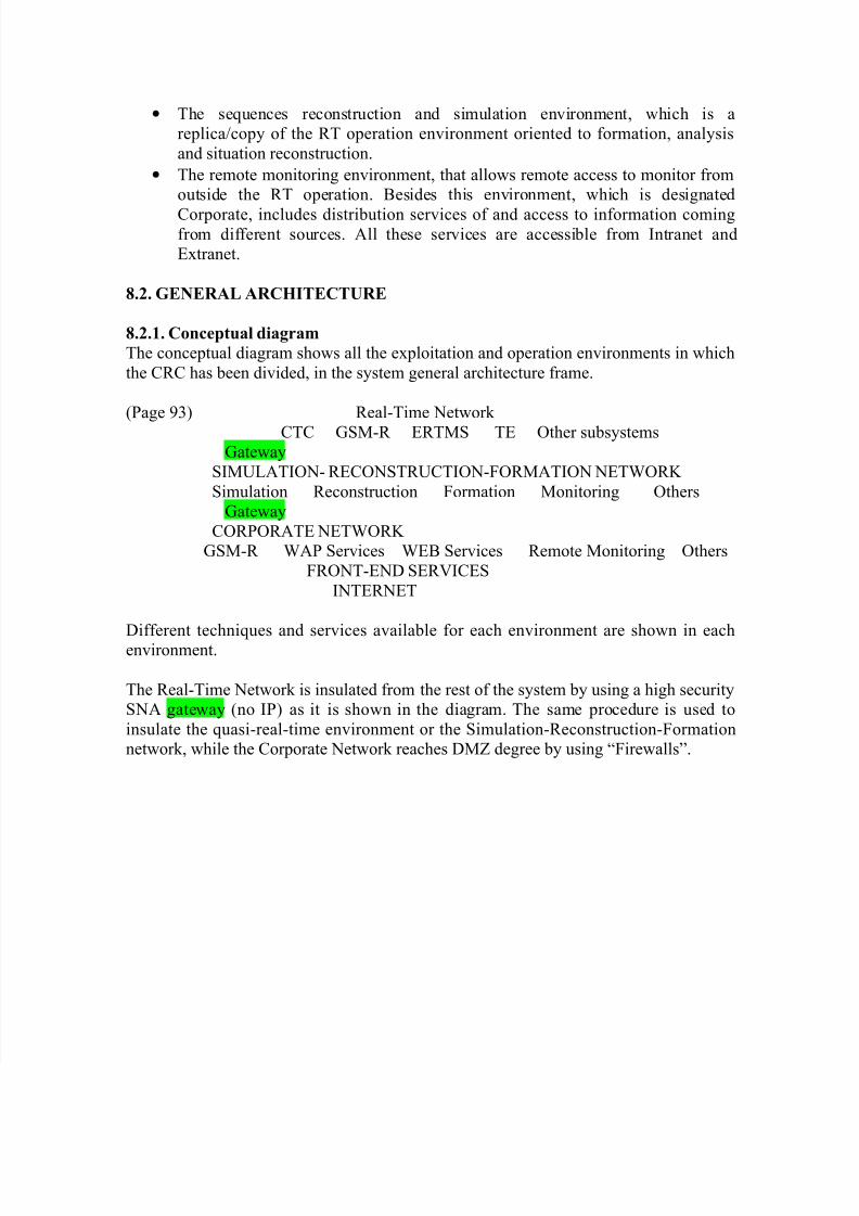
8.2.1. Conceptual diagram
The conceptual diagram shows all the exploitation and operation environments in which
the CRC has been divided, in the system general architecture frame.
(Page 93) Real-Time Network
CTC GSM-R ERTMS TE Other subsystemsGateway
SIMULATION- RECONSTRUCTION-FORMATION NETWORK
Simulation Reconstruction Formation Monitoring Others
Gateway
CORPORATE NETWORK
GSM-R WAP Services WEB Services Remote Monitoring Others
FRONT-END SERVICES
INTERNET
Different techniques and services available for each environment are shown in eachenvironment.
The Real-Time Network is insulated from the rest of the system by using a high security
SNA gateway (no IP) as it is shown in the diagram. The same procedure is used to
insulate the quasi-real-time environment or the Simulation-Reconstruction-Formation
network, while the Corporate Network reaches DMZ degree by using “Firewalls”.