Consumer Data Sheet Z1 Module Zone Controller · 2015-12-01 · SeaChange Data Sheet Z1 Part No LIT...
12
Main Features Controls Space Temperature in a Zone Optimum Start and Stop Control User Interface for any type of plant Engineering Display for Commissioning SeaChange Data Sheet Z1 Part No LIT / DAT / ZON / 001 Iss 3.1 Jun 00 Page 1 of 12 General Features Large Clear Display shows System Status and Current Settings Settings easily made using Dedicated Push Buttons and Rotary Adjustment Knob 2 Time Periods per Day: 7 Days per Week Special settings for Today and Tomorrow Holiday Period Feature Can be used to remotely display values from another module Can use temperature values from other modules for control Can be used to supervise the operation of other plant Condensation control for Chilled Ceilings Fabric Protection using temperature or Relative Humidity Can be used to display Alarms from the system External inputs for remote sensors or Occupancy Override signals Master / Slave operation Both Zone Controllers and Slave Zone Controllers are available. Slave Zone controllers take all of their time settings from a (master) Zone Controller, and hence do not have the relevant time control buttons. Users may still adjust their temperature setpoints and use the Override & Time Extension features. Slave Zone Controllers perform their own Optimum Start function independent of the master Zone Controller. Up to 100 Slaves can be associated with one Zone Controller. Zone Controller Data Sheet Z1 Consumer Module
Transcript of Consumer Data Sheet Z1 Module Zone Controller · 2015-12-01 · SeaChange Data Sheet Z1 Part No LIT...
Main Features
Controls Space Temperature in aZone
Optimum Start and Stop Control
User Interface for any type of plant
Engineering Display forCommissioning
SeaChange Data Sheet Z1 Part No LIT / DAT / ZON / 001 Iss 3.1 Jun 00 Page 1 of 12
General Features
Large Clear Display shows System Statusand Current Settings
Settings easily made using Dedicated PushButtons and Rotary Adjustment Knob
2 Time Periods per Day: 7 Days per Week
Special settings for Today and Tomorrow
Holiday Period Feature
Can be used to remotely display valuesfrom another module
Can use temperature values from othermodules for control
Can be used to supervise the operation ofother plant
Condensation control for Chilled Ceilings
Fabric Protection using temperature orRelative Humidity
Can be used to display Alarms from thesystem
External inputs for remote sensors orOccupancy Override signals
Master / Slave operation
Both Zone Controllers and Slave ZoneControllers are available.
Slave Zone controllers take all of their timesettings from a (master) Zone Controller,and hence do not have the relevant timecontrol buttons.
Users may still adjust their temperaturesetpoints and use the Override & TimeExtension features.
Slave Zone Controllers perform their ownOptimum Start function independent of themaster Zone Controller.
Up to 100 Slaves can be associated withone Zone Controller.
Zone Controller
Data Sheet Z1C o n s u m e rM o d u l e

SeaChange Data Sheet Z1 Part No LIT / DAT / ZON / 001 Iss 3.1 Jun 00 Page 2 of 12
Features
Status LampZone is in Occupancywhen indicator is lit.Indicator Flashes whencontroller is inconfiguration mode.
Temperature IndicatorShows whether the roomtemperature is at therequired temperature.Green when at the requiredtemperature.Red when colder thanrequired.Yellow when hotter thanrequired.
Occupancy IndicatorFigure inside house shows zones is in occupationand outside when not in occupation.During Optimum Start the figure jumps in and outof the house, during Optimum Stop, the figureflashes ON and OFF inside the house
Frost IndicatorShows that the system isrunning in frost or fabricprotection mode.
OverridePress button to changeOccupation status.Button also accessiblewith flap closed.Outside Occupationperiod Override starts aone hour occupationperiod.Within Occupation periodOverride puts zone intonon-occupation until nextscheduled start.
Time controlTime settings for two periods per day 7days per week..Today and tomorrow settings allow adjustment for thosedays only. Holiday feature allows up to 90 days of holidayto be set. Holiday becomes effective the day after settingis made.
Screwdriver SymbolFlashing: Alarm current insystemSteady:Indicatescontroller is inconfiguration mode.
Suitcase SymbolFlashing: indicatesHoliday mode is set, butnot activeSteady, with Seagullsymbol flashing:indicates Holiday modeactive
Rotary Knobis used to make alladjustments to times andtemperatures.
Registration Buttonis used during thecommissioning process tobuild logical links betweencontrollers.
User Instructionsare provided on the insideof the hinged flap.
SelectPress button and turnknob to view userdisplays from othercontrollers e.g.. OutsideAir Temperature, BoilerFlow Temperature
Main DisplayIndicates selectedTemperature and Time onlarge clear LCD.
Z1

SeaChange Data Sheet Z1 Part No LIT / DAT / ZON / 001 Iss 3.1 Jun 00 Page 3 of 12
Detailed Features
Variable- display will temporarily show RSET to showvariable has been reset- exit from config mode
Confirming the Source of a User Display which isalready set up
To confirm where a user display is coming from, putthe Zone Controller into config. mode, selectsuspected target module, turn knob clockwise withselect button depressed to locate suspected value, iftick displayed this is the displayed user value. If notick displayed then value can be updated by pressingthe appropriate buttons together (see Changing UserDisplays).
Remote PV (Process Variable)The Zone Controller normally uses the RoomTemperature either measured by its internaltemperature sensor or a remote sensor wired into itsterminals as the Process Variable that the Zone willcontrol.It is possible to use a temperature measurementbeing made by another module in the system as aRemote Process Variable in place of the RoomTemperature. The Zone Controller accesses thisinformation from the other module over thecommunications network.The Zone Controller will then display the new valueand 4-character label (e.g. POOL from a PoolController or HW T from a DHW Controller)in place ofthe ROOM temperature.To set Remote Process Variable- press and hold select + override buttons on Zone
until status lamp flashes (Zone in Config Mode)- press select on target module- press and hold select on Zone Controller- rotate Knob clockwise until target temperature value
shown- release select button- press copy & holiday buttons together.
A tick symbol will appear in the display- Unit will now display and work to new process
variable.Note this variable must be a measured temperatureparameter. Do not try to use a remote setpoint as aProcess Variable by this process.Be careful if using the Zone Controller to perform thecontrol of the temperature, because the ZoneController Fuzzy Logic constants are set assuming aslow moving Room temperature and may not copewell with a fast changing temperature.Alternatively, this feature may simply be used toremotely display an appropriate value (if, for instancethe Zone Controller is being used to set Return AirSetpoint in an AHU Controller using SetpointSupervision, then the measured temperature RTNAfrom that module should be displayed on the Zone).In this case, the HTSC and CLSC parameters in theZone Controller should be set to zero, to disablespurious Energy Demand signals to other modules(because the control is being done by the AHUmodule, not the Zone).See also Temperature Sensors and OccupancyInputs for details of Networked Temperature Sensors.
User Display OptionsThe Zone Controller can be used to display certainother parameters in the system which can beparticularly useful to installers and maintenance staff.
Viewing User Displays:
To view user display parameters-press and hold select button-rotate Knob clockwise to show parameters.
Preset (factory default) parameters are:
1 Room Temperature ROOM2 Required Temperature REQD3 Outside Temperature OUTS4 Boiler flow temperature FLOW5 Zone Control Demand DEMD6 Time & Day MON-SUN
Release button:Display will continue to show parameter selected
To return the display to Room Temperature- press & hold select button- rotate Knob anti-clockwise to beginning of list to
show ROOM- release button
Changing User DisplaysIt is possible to reconfigure two of the user displayparameters - Nos 3 & 4 - to read other systemparameters than those preset. This can be used todisplay temperatures from other modules e.g. POOLtemperature or DHW temperature.
- put zone into configuration mode and selectrequired parameter on target module
- by pressing & holding select + override buttons untilstatus display flashes
- press select on target module- press & hold select on Zone Controller- rotate Knob until Required Temperature value
shown- release select button- press start 1 & start 2 buttons together to change
user display 3 (preset to Outside Temperature) atick symbol will appear in the display.
- press stop 1 & stop 2 buttons together to changeuser display 4 (preset to Boiler flowtemp) a ticksymbol will appear in the display.
- return Zone to normal mode - press select andoverride together.
Note only temperature variables should be selectedfor these user displays.
To Reset User Displays to Factory Defaults:
- put Zone into config mode- push pair of buttons used to set particular variable
i.e.start 1 - start 2 for user display 3stop 1 - stop 2 for user display 4copy & holiday for Room Temperature Process
Z1
SeaChange Data Sheet Z1 Part No LIT / DAT / ZON / 001 Iss 3.1 Jun 00 Page 4 of 12
Temperature ControlOptimum Start (OPST)The Occupation Time periods define the times thatthe building or zone will be to temperature andsuitable for occupation.The Controller will bring on the heating services orHVAC system for a boost period before the beginningof the occupation period to bring the building to therequired temperature. The boost period is varieddepending on both the zone temperature and theoutside temperature in order to bring the zone just upto the required temperature by the beginning of theoccupation period. This feature is known as optimumstart. By changing the boost time, energy is saved asthe plant does not run longer than actual conditionsrequire, the Zone Controller adapts the parameters inits optimum start algorithm so it learns thecharacteristics of the building and of the servicesplant.The Zone learns different characteristics for heatingand cooling modes because the plant will havedifferent characteristics in each mode.
Two Parameters can be adjusted to affect OptimumStart; MXOS is used to limit the length of the boostperiod. With undersized plant, it may not be possibleto reach the Occupied Setpoint on very cold dayswithout an excessively long boost period, so thelength of the boost period may need to be limited.The OPTE parameter may be used to allow theOptimum Start algorithm to aim for a setpoint lowerthan the Occupied Setpoint; this is useful where astep change in heat gain occurs at Occupancy Start,due to lots of people entering the space (e.g. schools)or equipment being turned on. The use of the OPTEparameter can prevent temperature overshoot underthese conditions.During the Optimum Start period the figure on thedisplay jumps in and out of the house.
Optimum StopThe services for a zone can often be turned off beforethe end of occupation without the temperature fallingoutside acceptable conditions. The optimum stopcontrol algorithm calculates how long before the endof occupation the services can be switched off basedon zone temperature, outside temperature and itslearned characteristics of the building.The maximum optimum off period is preset to 2 hoursconfigurable by MXOF. Setting the parameter of 0disables the optimum off function which is the preset.Note that the optimum off function turns off theheating or cooling only . Fresh air and ventilation plantwould continue to run until the normal end of theoccupation period. The target temperature foroptimum off can be offset from the RequiredTemperature by setting the configuration parameterSBDB - preset to 0°C.During the Optimum Stop period the figure on thedisplay flashes ON and OFF inside the house.
Required TemperatureThe Zone Controller normally displays the Roomtemperature.To View and Change the Required Temperature:- rotate the adjustment knob by one click; the display
shows Required Temperature (REQD). After a fewseconds the display reverts to Room Temperature(ROOM) displayed.
The Required Temperature is preset to 20°C; tochange the Required Temperature rotate the knobmore than one click. Clockwise to increase, anti-clockwise to decrease.
Intelligent Setpoint
The Zone Controller has a number of functions thatlimit the adjustments that the user can make to thetemperature in order to ensure comfort and energyefficient operation are maintained.
Setpoint Adjustment LimitChanges that can be made to the RequiredTemperature using the knob are limited to 2degC at atime (the adjustment limit) to prevent usersunthinkingly making large adjustments that wouldimpair the energy efficiency of the system. After a fewminutes the Required Temperature can be alteredfurther. The adjustment limit is a configurationparameter SPAS which is preset to 2°C
Adjustment RangeThe total Adjustment Range of the RequiredTemperature is limited to prevent it being set tounacceptable conditions. The Adjustment Range ispreset to 5°C about the range midpoint temperaturewhich is preset to 20°C. The Adjustment Range andMidpoint can be set by configuration parameters,SPRG & SPMD.
Required Temperature ReversionAt the beginning of each day the RequiredTemperature reverts to its Default value so that anychanges made the previous day are lost and thecontrol returns to an energy efficient default. TheDefault temperature can be configured to beanywhere within the Adjustment Range and is presetto 20°C (configuration parameter SPOC). TheRequired Temperature Reversion feature can bedisabled by setting the configuration parameter SPDFto zero.
Heat - Cool ControlThe Zone Controller has the ability to control coolingas well as heating and can work through separateplant and actuator controllers for both heating andcooling.It is normal to set a dead band between the heatingand cooling functions to allow the temperature to floatbetween the two modes which will improve energyefficiency. The dead band is configured by the SPDBparameter. It is preset to 0 which disables the coolingcontrol loop. Setting between 1 to 10°C enablescooling control and sets the cooling dead band.
Detailed FeaturesZ1
SeaChange Data Sheet Z1 Part No LIT / DAT / ZON / 001 Iss 3.1 Jun 00 Page 5 of 12
Fabric Protection - using TemperatureDuring the occupation period the Zone controls to theRequired Temperature. Outside the occupationperiod, the zone will bring on the services if thetemperature falls to the Fabric Protection Temperaturein order to avoid condensation forming.Once the Fabric Protection algorithm has beeninitiated it will bring the temperature up by the FabricRise Temperature in order to avoid the plant cyclingON and OFF. The Zone remains in this mode until thetemperature has risen by the amount specified by theparameter FRSE at which point the Zone Controllerreverts to non-occupied setpoint as before. If a stabletemperature is required during non-Occupancy (e.g.night setback for a nursing home) then FRSE can beleft set to the factory default setting of zero.The Fabric protection temperature is a configurationparameter SPNC and is preset to 10°C.When the Zone is running the plant in FabricProtection mode a snowflake symbol appears on thedisplay.
Fabric Protection - using Relative HumidityIf a Networked T+RH sensor is registered to the ZoneController, the Humidity value may be used for FabricProtection; the Zone Controller can be made to bringon the heating to prevent RH levels rising above apredetermined level.The desired maximum RH level is set on parameterSPRH (Rh setpoint); setting a non-zero value willenable RH Fabric Protection.If the RH is below the RH setpoint, the Zone willcontrol to its normal non-occupied setpoint (set onSPNC) as for temperature-based Fabric Protection.As the RH in the space rises, the Zone Controller willincrease its current setpoint (which can be read onMonitoring Parameter REQD) at a maximum rate of0.1 degC per minute according to an integratingcontrol action. As this temperature setpoint exceedsthe current temperature in the space, so the heatingwill be enabled, raising the temperature and thusreducing the Relative Humidity. The temperaturesetpoint is limited to the normal Occupied setpoint forthe zone (set on SPOC) thus providing a high limit forspace temperature.
Frost ProtectionThe Zone Controller is made aware of the Frostprotection status of the Boiler Controller. If the ZoneController alarms are enabled (ALRM set greater thanzero) then the Zone will receive frost (FRST) alarmsfrom the Boiler. If the Boiler is in Frost protect this iscommunicated to the zones which will display the frostsymbol and open any registered actuators to 50% andstart any optimum start/stop switched loads. The Zoneremains in non-occupied (man out of the house) todistinguish this mode from Fabric Protection.
Occupancy Control
Time SchedulesThe user can set the times that the Zone is to be used- called occupation periods - by setting the timeschedule. This allows 2 occupation periods per dayand different settings for each day of the week.Preset times are:one occupation period: 0830 to 1700 Mon - Frino occupation: Saturday & Sunday
System ClockAll Zones share a common system clock function soon multi zone systems it is only necessary to set theclock and day on one zone - all the other zones willreceive and use the updated time and day.
The Real Time Clock (RTC) is located in the SystemHousekeeping Module and this module broadcaststhe time information over the network every minuteand this is received and used by all modules thatrequire this information. If the Zone Module fails toreceive the time update - (for instance if the SystemHousekeeping Module is disconnected or is inconfiguration mode when it will not communicate)then the zone will automatically switch to use itsinternal software based clock until the time signals arerestored.The Zone Controller alerts the user bybringing an X symbol in the lower part of the displaywhen it is running on its software clock.
Setting the System ClockTo Set Current Time:- Press and hold clock button- Rotate Knob until correct time shows on display- Release Button
To Set Current Day:- Press and hold day & clock buttons together- Rotate Knob until correct day shows in display- Release Buttons
Setting the 7 Day Time ScheduleSelect the Day to be changed:- press & hold day button- rotate Knob to select day- release button
View and adjust time periods:- press and hold Start 1 butt- Display shows current start time for period one- rotate Knob until display shows required start time- release button- Set Stop 1 for end of period 1 in same way- Set second time period using Start 2 and Stop 2 in
same way (if required).
To skip an Occupation Period:The controller will skip an occupation period if thestart and stop times are set the same. The defaulttimes are to skip the second occupation Monday toFriday preset to 24:00 and both periods Saturday &Sunday preset to 00:10.
Detailed Features Z1

Detailed Features
Copy FeatureHaving set the occupation periods for one day theycan be copied to other days of the week using thecopy facility.- select the day to be copied from using the day
button- press and hold the copy button- rotate Knob until last day in copy sequence shows
in display- release button
The occupation times have been copied, from theinitial day to all the days, including the final day in thesequence. The copy process can go both forward(Mon to Fri) and back (Fri to Mon) depending onwhich way the knob turned.The variable display shows both the initial day and thefinal day in the sequence as day number 1 - 7,Monday is day 1 and Sunday day 7, so copy fromMonday to Friday and the variable display will show01:05
Today & TomorrowThe time periods for today and tomorrow can be setto be different from the normal 7 day time periods butthey are volatile and the system will revert to thenormal 7 day time periods when they are over. This isuseful for unusual events (e.g. late working, or earlystarts) which are not repeated every week.
To set times for today and tomorrow:- select day- press and hold day button- for TODAY rotate Knob Anti clockwise until display
shows TDAY (for Today) which is before MON- for TOMORROW rotate Knob clockwise until
display shows TMRW (for Tomorrow) which isafter SUN
- press start and stop buttons to display current timeperiods
- press and hold start and stop buttons and rotateknob to set special times
- release button
OverrideOccupation Status is shown on the display During anoccupied period, the figure is in the house, outsideoccupation the figure is outside.
The user can Override the Occupation Status usingthe Override Button that appears through the flap onthe front of the controller.
The way the Override works changes depending onthe periods of the day when override is used.
If used before the beginning of either Occupationperiod in the day, then the zone will be Occupied untilthe end of that Occupation period. If Override is usedwhen the zone is Occupied, then the unit will switch tonon Occupied until the start of the next time period. IfOverride is used after the end of the Occupationperiods then there will be a timed extension to theOccupation period. This extension period is preset to1 hour but may be changed by using configurationparameter XHRS.
HolidayThe Zone Controller can be set to Holiday Modewhich is the number of days holiday period startingfrom the following day. Occupation periods can be setfor holiday (for cleaners etc.); the preset value is forno occupation period.To set Holiday Occupation period :- press and hold day button- rotate knob clockwise until HOLS displayed - This
is after SUN & TMRW- release day button- press and hold start 1 button- rotate knob to show required start time- release button- repeat for Stop 1 & period 2
To set Holiday Mode :- press and hold holiday button- display shows number of days holiday starting
from tomorrow- rotate knob to display required number of holidays,
14 for 2 weeks etc.- release button
When Holiday Mode has been set (but is not active,i.e on the last working day) the display will indicatethis by showing a flashing “Suitcase” symbol. WhenHoliday Mode is active, the display will show steady“Suitcase” and flashing “Seagull” symbols.
RegistrationThe Zone Controller can be used in several differentways, for Controlling the Zone temperature directly,for supervising other controllers in various ways, or fordemanding services from other controllers. Some ofthese features are mutually exclusive, whilst somecan co-exist at the same time.The various forms of Logical Links between this ZoneController and other Controllers are made by theprocess of Registration; a brief description of theprocess is given below. For a full description, see ourCD ROM.
Address AllocationBefore any Registration Links can be made, the ZoneController must be allocated an address by theSystem Housekeeping Module. The Register button ispressed; the Zone should display its address;“ZONE1”, “ZONE2” etc.
SubmodulesThe Zone Controller may have up to 8 Submodules(e.g. Actuator Controllers, Pump ChangeoverModules) registered to it. The Zone is put intoConfiguration Mode and the Submodule is registeredto it. This sets up the Submodule’s address (which willbe of the form Zn Am , where n is the Zone’s address,and m is the Submodule’s address).The registration process also makes Control Demandlinks between Zone and its Submodules, so that theywill respond to Occupancy and Heating/Coolingdemand signals from the Zone as appropriate.
SeaChange Data Sheet Z1 Part No LIT / DAT / ZON / 001 Iss 3.1 Jun 00 Page 6 of 12
Z1

Detailed Features
Networked SensorsThe Zone Controller may have a Networked Sensorregistered to it; either a Condensation sensor, aNetworked Temperature sensor, or a NetworkedTemperature + Relative Humidity sensor. Only onesensor may be registered to a Zone. The Zone is putinto Configuration Mode and the Sensor is registeredto it.
Demand LinksThese links are Many-to One links made from thisZone (and perhaps many others) to a Module that isproviding a service to the Zone (provision of FreshAir, Energy or Domestic Hot Water services). Theycan each exist with any other links simultaneously.
Occupancy DemandThe Occupation state of the Zone can be passed toan AHU or DHW Controller using Occupancy Demandlinking; this is for plant which provides a service formany zones (e.g. Fresh Air plant). The Target Moduleis put into Configuration Mode, and the Zone registerto it. This sets up the Occupancy Destinationparameter OCDS to “point” the Zone’s OccupancyDemand at the target, which will then run when theZone (or any other Zone thus registered) is inOccupancy. Occupancy Demand linking can be usedin conjunction with any other links at the same time.Energy DemandThe Zone Controller can send its Energy Demands forHeating and Cooling to another Module (a DistributorModule, like a Secondary Circuit Controller orProvider Module like a Boiler Controller) if that Moduleis responsible for providing energy to the Zone. TheDistributor/Provider Module is put into ConfigurationMode, and the Zone is registered to it. This sets upthe HTSC and CLSC parameters in the Zone to“point” the Energy Demands at the appropriateModules. Energy Demand linking can be used inconjunction with any other links at the same time.
Supervision LinksThese links are One-to Many links made from thisZone to one or many other Modules. The ZoneController will supervise the behaviour of these othermodules in some way; either their Setpoint,Occupancy Status (i.e whether they are On or Off) ortheir Time Schedules (so that they can still performtheir own Optimum Start and Fabric Protection). TheZone Controller can only have one of the 3 types oflink with any given Module, but it may have links ofeach type with several different Modules concurrently(e.g. it can supervise the Setpoint in an AHUController, and send Occupancy Times to a Slve ZoneController at the same time)..
Setpoint Supervision:The Zone Controller can be used to transmit itsSetpoint to another Module (e.g. an AHU Controller)or to many other Contollers (e.g. Fan Coils).Parameters in the Supervised Modules will need to beset (typically their SPTY parameter -see appropriateData Sheets for details).The SLVM parameter in the Zone must be set to 2 or3 (a setting of 3 will allow the Zone to also send
Occupancy Times to a different Controller). The ZoneController is put into Configuration Mode, and thetarget Controller(s) are registered to it. This SetpointMaster-Slave link will be confirmed by “SLVE” (forZones, Fan Coils etc.) or “SAHU” appearing in theZone’s display.AHU Controllers thus supervised would normally runto the Zone’s setpoint during Occupancy, and will turnoff during Non-Occupancy. If it is desired to run theAHU during Non-Occupancy (i.e for 24 hours) but at adifferent setpoint, the parameter NOSV may be used ;if set to a non-zero value, this will keep the AHUrunning at the desired setpoint.Occupancy Supervision:The Zone Controller can be used to transmit itsOccupancy Status to many other Contollers (e.g. FanCoils). This mode of linking can be used instead ofSetpoint Supervision to drive Fan Coils on and off, butleave them controlling to their own setpoints. TheZone Controller will be responsible for Optimum Startand Fabric Protection.Parameters in the Supervised Modules will need to beset (typically their SPTY parameter -see appropriateData Sheets for details).The SLVM parameter in the Zone must be set to 2 or3 (a setting of 3 will allow the Zone to also sendOccupancy Times to a different Controller). The ZoneController is put into Configuration Mode, and thetarget Controller(s) are registered to it. This SetpointMaster-Slave link will be confirmed by “SLVE” (forZones, Fan Coils etc.) or “SAHU” appearing in theZone’s display.Time Schedule Supervision:The Zone Controller can be used to transmit itsOccupancy Time Schedules to many other Contollers(e.g. Slave Zone Controllers). This mode of linkingcan be used instead of Setpoint Supervision to setOccupancy Times but leave them controlling to theirown setpoints, and performing independent OptimumStart and Fabric Protection for their parts of thebuilding.Parameters in the Supervised Modules will need to beset (typically their SPTY parameter -see appropriateData Sheets for details).The SLVM parameter in the Zone must be set to 1 or3 (a setting of 3 will allow the Zone to also sendSetpoints to a different Controller). The ZoneController is put into Configuration Mode, and thetarget Controller(s) are registered to it. This SetpointMaster-Slave link will be confirmed by “SLVE” (forZones, Fan Coils etc.) or “SAHU” appearing in theZone’s display.
SeaChange Data Sheet Z1 Part No LIT / DAT / ZON / 001 Iss 3.1 Jun 00 Page 7 of 12
Z1
Detailed Features
Temperature, RH and OccupancyInputs
Conventional Thermistor SensorsThe Zone Controller (type /001) is fitted with its owninternal temperature sensor which is used as themeasured temperature to be controlled.
The unit can be connected to a remote temperaturesensor which is a conventional, low cost thermistortype for applications where it is inappropriate to locatethe Zone Controller in the area to be controlledbecause it may be tampered with. The ZoneController is preset to switch control to the remotesensor if one is fitted but the sensor action parameterSACT can be set so the controller uses the higher,lower or average value of the two sensors. If onesensor fails the control will continue on the othersensor alone. A Sensor fail alarm can be sent.
A version (/003) of the Zone Controller is availablewithout an Internal Temperature sensor but with theability to use 2 remote sensors. This is useful toprovide freedom of location of sensors and to allowtwo measurement points in a larger space.
Because they are standard 10K ohm thermistors, 4can be wired in series/parallel configuration to provideelectrical averaging of 4 sensors. Thus up to 8sensors can be wired to a Zone Controller.
Intelligent Networked Sensors- Temperature
A SeaChange Intelligent Networked TemperatureSensor (which has its own Microprocessor andderives its power from the network) may be registered(as a Submodule) to the Zone Controller. The Zonewill display SEN1 when the device is registered. Thistype of sensor has the advantage that it may belocated anywhere on the network, and so may provideinstallation benefits because an additional cable maynot need to be run between the Zone and the sensor.The parameter SACT must be adjusted accordingly tomake the Zone Controller use the Networked Sensorvalue as its Process Variable in place of its ownthermistor. Control will revert to the local thermistor ifthe Networked Sensor reading is invalid.Unlike the feature Remote Process Variable,(described under User Display Options) where theProcess variable is obtained from another ControllerModule, here the value is coming from a SensorSubmodule, so the Zone Display will still read“ROOM”.
- Temperature + HumidityA SeaChange Intelligent Networked T + Rh sensorconnected somewhere on the network may beregistered (as a Submodule) to the Zone Controller.The Zone will display SEN1 when the device isregistered. The parameter SACT must be adjustedaccordingly to make the Zone Controller use theNetworked Sensor Temperature value as its ProcessVariable in place of its own thermistor. Control willrevert to the local thermistor if the Networked Sensor
reading is invalid.The Relative Humidity may be used for Monitoringonly, or it may be used for enhanced FabricProtection using Rh control - see Fabric Protection.
Sensor CalibrationThe sensor calibration can be trimmed using theSCAL parameter. This provides a fixed offset to thetemperature measurement and applies to the resultanttemperature - after selection of remote, average, etc.functions using SACT parameter. Sensor calibration ispreset to 0°C.
Switch Inputs
Remote Occupation Status InputA Volt-Free Contact (VFC) may be wired to theexternal input connections to provide external controlover the Occupation Status of the controller.
Occupancy/Non-Occupancy SwitchingThe remote temperature input connections can beconfigured by SACT to be a remote input to provideoccupation override. This uses a contact closure (voltfree contact) to drive the zone into the occupancystate if it currently is not occupied but will not alter theoccupancy state if the time schedule etc., has alreadyput the zone into occupancy. This feature can beused to drive a zone into occupancy using an inputfrom a simple switch, another item of plant, or aPresence Detector or Card Access Controller. Notethat any timed on period should be part of thepresence detector function, the Zone Controller willrevert to Non-occupied directly the signal is removed.
Occupancy/Standby Mode SwitchingThe remote temperature input connections can beconfigured by SACT to be a remote input to provideOccupation/ Standby Mode switching. This uses acontact closure (volt free contact) to drive the zoneinto the occupancy state if it is currently outside of itsOccupation Times. If the Zone is in its normalOccupancy period, with the external contact opencircuit, it will be running in Standby Mode (i.e with awide deadband set on parameter SBDB).When the external contact closes, the Zone will bedriven into its normal Occupation Mode (with a normalclose deadband set on SPDB). This feature can beused to drive a zone into occupancy using an inputfrom a simple switch, another item of plant, or aPresence Detector or Card Access Controller. Notethat any timed on period should be part of thepresence detector function, the Zone Controller willrevert to Non-occupied directly the signal is removed.
SeaChange Data Sheet Z1 Part No LIT / DAT / ZON / 001 Iss 3.1 Jun 00 Page 8 of 12
Z1

Detailed Features
Condensation Control
The Zone Controller can control condensation inStatic Cooling (Chilled Ceiling and Chilled Beam)installations, where condensation can form on thecold surfaces of the ceiling if the ceiling temperatureis allowed to fall below the dewpoint of thesurrounding air. This phenomenon is sometimesrefererred to as “Office Rain”.
A SeaChange Intelligent Networked CondesationSensor must be registered to the Zone Controller (thesensor can be connected anywhere on the network).Upon registration, the Zone Controller will display“SEN1”.If the Condensation Sensor reports a condensingcondition, the Zone Controller will progressively rampdown its Cooling Control demand signal, and hencestart to close down any registered ActuatorSubmodules, which would be controlling the CoolingValve on the Chilled Ceiling. An alarm can also begenerated; see Alarm Handling and Display.As the condensing condition clears, the ZoneController will resume normal control; thus a simpleform of local Dewpoint Control has been created. TheController will allow the Chilled Ceiling to run as coldas possible whilst preventing condensation, which willensure that the maximum possible cooling output isderived from the ceiling.If the Condensation Sensor fails to respond orbecomes disconnected during a condensing event,the Zone Controller will recover normal operationwithin 7 minutes, until the sensor is re-connected.
Alarm Handling and Display
The Zone Controller can generate alarms, and canalso respond to alarms sent by other Controllers. If itreceives an alarm, it can be set to take some controlaction, display the alarm, or both.
Alarm GenerationThe Zone Controller can generate 3 different alarms,which can be reported at Doorway Supervisor, or onthe display of this Zone Controller (see below).
SENF alarm is generated when the sensor readingis outside of the allowable rangeRPVF alarm is generated if the Controller is set touse a Remote Process Variable from anothercontroller in place of its own sensors, and theVariable is not being received across thenetworkCNDF alarm is generated when a Condensationsensor registered to this Zone has detectedcondensation.
Alarm Control ActionThe Zone Controller can be set to react to alarms indifferent ways; the ALRM parameter can be set toignore alarms, to report alarms but take no ControlAction, or to shut down its Control Demand output(and hence any registered Submodules’ outputs, e.g.Actuator Controllers) - either because of an internalalarm, or because a System STOP alarm has beenreceived.
Alarm DisplaysThe Zone Controller can be set to display alarms ifrequired. The setting can make the Zone display onlyits own alarms, or alarms from any other Controller onthe network.The parameter AMON when set to a non zero valuesenables the Alarm Monitoring feature. The controllerstores the first 10 Controllers which report alarms andthe display flashes “HELP” and the current number ofControllers which have reported alarms, alternatingwith the normal display (usually ROOM and thetemperature value). If the Alarm is generated by theZone controller itself then the display will show theAlarm label instead of HELP.
Pressing override acknowledges the alarm and thedisplay reverts to normal except that the screwdriversymbol continues to flash until the alarms clear.
This feature has been developed to provide simplealarm indication on small systems so that theoccupants can alert their maintenance company thatthere is a fault. Alternatively it can be used to showsensor fail or condensation imminent for just the zoneaffected.
SeaChange Data Sheet Z1 Part No LIT / DAT / ZON / 001 Iss 3.1 Jun 00 Page 9 of 12
Z1

SeaChange Data Sheet Z1 Part No LIT / DAT / ZON / 001 Iss 3.1 Jan 00 Page 10 of 12
Configuration ParametersLabel
SACT
SCALSPMDSPRGSPDB
SBDB
SLVM(master
only)
SPTY(slaveonly)
MNOP
XHRSDEGFFRSE
SPAJ
SPDF
ALRM
ALSTAMON
HTSCCLSCOCDS
HTCT
CLCTISS3
DoorwayCode
C1
C2C3C4C5
C6
C7
C7
C8
C9C10C11
C12
C13
C14
C15C16
C17C18C19
C20C21C22C23C24
Description
Sensor Action; sets pre-processing for temperature input andselects external input modes.
0: use local sensor unless remote hardwired sensor connected(see use of nviRemoteTemp for Open systems)
1: average of valid sensor values2: maximum of valid sensor values3: minimum of valid sensor values4: use remote sensor as Occupation input , VFC shorted isoccupied5: use networked temperature (nviRemoteTemp) if valid, else
remote hardwired if valid, else local6: use remote sensor as Occupancy / standby input, VFC
shorted is occupied with close control. open circuit is standbyor non-occupied according to zone occupancy pattern
Calibrate sensor valueMidpoint of absolute setpoint adjustment rangeRange of absolute setpoint adjustment about midpointSetpoint deadband between heating and cooling setpoints. Ifzero disables coolingAdditional deadband used in Standby Mode and Optimum off
Slave Mode; (only in Master Zones)1: send Occupation times to Slave Zones2: send Setpoint to Slave Zones3: send both Times and setpoint to Slaves
Setpoint Type; (only in Slave Zones)0: use local setpoint1: use remote setpoint, disable local OSS
Minimum output invoked if within 1C of setpoint, used to keep VTcircuit running (alternative to using MIND = 0 in VT Controller)Extension hours when override pressed outside occupationSelects displays in degrees Fahrenheit when set to 1Fabric/Frost rise; added to SPNO to form terminationtemperature for heating run if temperature dips below SPNOvalue during non-occupationSetpoint Adjust;
range of instantaneous setpoint adjustment using knobSetpoint Default;
If set to 1 setpoint changes with the knob update the defaultsetpoint (i.e. the setpoint will not revert to a default during thenext occupancy period)
Alarm mode;0: ignore alarms1: report alarms2: report alarms, shut down all outputs (i.e. Submodules) on
alarm3: report alarms, shut down all outputs (i.e. Submodules) on
STOP alarm or sensor fail alarmnot useddisplays that alarms are present on the Zone Display0: disables alarm monitoring1: only monitors own alarms2: only monitors alarms from own domain3: monitors all alarmsHeat Source; points Energy Demand to source of Heating energyCool Source; points Energy Demand to source of Cooling energyOccupation Destination;
points Occupancy Demand at another controllerSetpoint selector;0: send Heating Demand signal as % (for VT Circuit Control)1- 100: send this value as CT setpoint (for CT Circuit Control)reserved for future useSet to force single domain operation (should only be neededwhen using issue 3 Floor Controllers)
Units
-
Deg CDeg CDeg CDeg C
Deg C
-
-
%
hours-
Deg C
Deg C
Deg C
-
--
---
-
--
%
hrs-
DefaultValue
0
020.0
50
2.0
1
1
0
100
2.0
0
1
0
-0
100
0
00
Range
0 to 6
-5.0 to 5.05 to 950 to 100 to 10
0 to 10
1 to 3
0 to 1
0 to 10
0 to 8.00 to 1
0 to 10.0
0 to 10.0
0 to 1
0 to 3
0 to 1
-0 to 3
0 to 82550 to 82550 to 8255
0 to 100
0 to 200 to 1
Z1
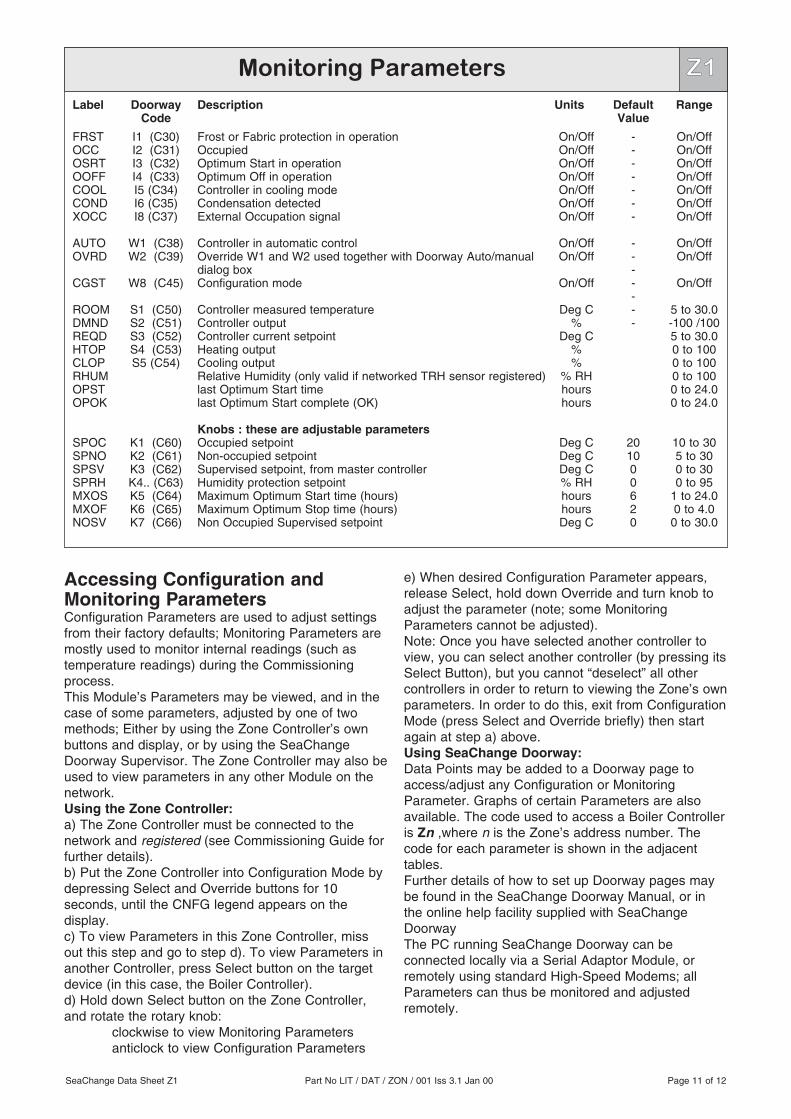
Accessing Configuration andMonitoring ParametersConfiguration Parameters are used to adjust settingsfrom their factory defaults; Monitoring Parameters aremostly used to monitor internal readings (such astemperature readings) during the Commissioningprocess.This Module’s Parameters may be viewed, and in thecase of some parameters, adjusted by one of twomethods; Either by using the Zone Controller’s ownbuttons and display, or by using the SeaChangeDoorway Supervisor. The Zone Controller may also beused to view parameters in any other Module on thenetwork.Using the Zone Controller:a) The Zone Controller must be connected to thenetwork and registered (see Commissioning Guide forfurther details).b) Put the Zone Controller into Configuration Mode bydepressing Select and Override buttons for 10seconds, until the CNFG legend appears on thedisplay.c) To view Parameters in this Zone Controller, missout this step and go to step d). To view Parameters inanother Controller, press Select button on the targetdevice (in this case, the Boiler Controller).d) Hold down Select button on the Zone Controller,and rotate the rotary knob:
clockwise to view Monitoring Parametersanticlock to view Configuration Parameters
e) When desired Configuration Parameter appears,release Select, hold down Override and turn knob toadjust the parameter (note; some MonitoringParameters cannot be adjusted).Note: Once you have selected another controller toview, you can select another controller (by pressing itsSelect Button), but you cannot “deselect” all othercontrollers in order to return to viewing the Zone’s ownparameters. In order to do this, exit from ConfigurationMode (press Select and Override briefly) then startagain at step a) above.Using SeaChange Doorway:Data Points may be added to a Doorway page toaccess/adjust any Configuration or MonitoringParameter. Graphs of certain Parameters are alsoavailable. The code used to access a Boiler Controlleris Zn ,where n is the Zone’s address number. Thecode for each parameter is shown in the adjacenttables.Further details of how to set up Doorway pages maybe found in the SeaChange Doorway Manual, or inthe online help facility supplied with SeaChangeDoorwayThe PC running SeaChange Doorway can beconnected locally via a Serial Adaptor Module, orremotely using standard High-Speed Modems; allParameters can thus be monitored and adjustedremotely.
Monitoring ParametersLabel
FRSTOCCOSRTOOFFCOOLCONDXOCC
AUTOOVRD
CGST
ROOMDMNDREQDHTOPCLOPRHUMOPSTOPOK
SPOCSPNOSPSVSPRHMXOSMXOFNOSV
DoorwayCode
I1 (C30)I2 (C31)I3 (C32)I4 (C33)I5 (C34)I6 (C35)I8 (C37)
W1 (C38)W2 (C39)
W8 (C45)
S1 (C50)S2 (C51)S3 (C52)S4 (C53)S5 (C54)
K1 (C60)K2 (C61)K3 (C62)K4.. (C63)K5 (C64)K6 (C65)K7 (C66)
Description
Frost or Fabric protection in operationOccupiedOptimum Start in operationOptimum Off in operationController in cooling modeCondensation detectedExternal Occupation signal
Controller in automatic controlOverride W1 and W2 used together with Doorway Auto/manualdialog boxConfiguration mode
Controller measured temperatureController outputController current setpointHeating outputCooling outputRelative Humidity (only valid if networked TRH sensor registered)last Optimum Start timelast Optimum Start complete (OK)
Knobs : these are adjustable parametersOccupied setpointNon-occupied setpointSupervised setpoint, from master controllerHumidity protection setpointMaximum Optimum Start time (hours)Maximum Optimum Stop time (hours)Non Occupied Supervised setpoint
Units
On/OffOn/OffOn/OffOn/OffOn/OffOn/OffOn/Off
On/OffOn/Off
On/Off
Deg C%
Deg C%%
% RHhourshours
Deg CDeg CDeg C% RHhourshoursDeg C
DefaultValue
-------
-------
201000620
Range
On/OffOn/OffOn/OffOn/OffOn/OffOn/OffOn/Off
On/OffOn/Off
On/Off
5 to 30.0-100 /1005 to 30.00 to 1000 to 1000 to 1000 to 24.00 to 24.0
10 to 305 to 300 to 300 to 95
1 to 24.00 to 4.0
0 to 30.0
SeaChange Data Sheet Z1 Part No LIT / DAT / ZON / 001 Iss 3.1 Jan 00 Page 11 of 12
Z1

SeaChange Data Sheet Z1 Part No LIT / DAT / ZON / 001 Iss 3.1 Jun 00 Page 12 of 12
Options and Product Codes
ZON / PTR / LCD / [option] / [colour]
ZSL / PTR / LCD / [option] / [colour]
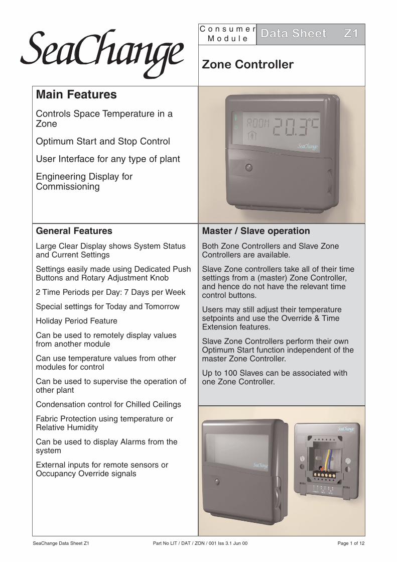
Specification
all dimensions in mm
ElectricalInputs 1 x remote sensor or VFC (type /001) or
2 x remote sensors or 1 sensor and 1VFC (type /003)
Outputs NoneConsumption 11mA from networkPhysicalWeight 0.25 kgCover Material PC/ABS alloy Self extinguishing to
UL 94 V0/1.60Base Material Polyamide 6.6 Self extinguishing to
UL 94 VO
Conformant product
Wiring Information
Dimensions
8 Horsted SquareBell Lane Business ParkUckfield East Sussex TN22 1QQ
phone 01825 769812fax 01825 769813e-mail [email protected]:// www.seachange.co.uk
Z1
Options/ 001 with internal sensor, provision for 1 remote sensor or override device
/ 003 with no internal sensor for use with 2 remote sensors or 1 remote sensor and anoverride device
Options/ 001 with internal sensor, provision for 1 remote sensor or override device
/ 003 with no internal sensor for use with 2 external sensors or 1 remote sensor and anoverride device
Colour/ G Grey housing
/ W White housing