
Construction Standards and Specifications...
208
DEPARTMENT OF ENVIRONMENTAL SERVICES Engineering Bureau 2100 Clarendon Boulevard, Suite 801, Arlington, VA 22201 TEL 703-228-3686 FAX 703-228-3606 www.arlingtonva.us February 17, 2012 To: Users of the Arlington County Department of Environmental Services Construction Standards & Specifications I am pleased to release an update to the County’s Construction Standards and Specifications. The Standards can be found online at: http://www.arlingtonva.us/departments/EnvironmentalServices/cpe/EnvironmentalServicesSpecs.aspx This February 2012 release is the first step in a comprehensive revision to the document, and the initial release of changes are concentrated within the Sections 01000 – 02200. We will continue to work through the remaining sections and release updates to those sections over the coming year. I have noted some of the most significant changes for this initial release below: The General Conditions preamble has been eliminated – the subject matter which had been covered in this document is now contained either within Section 01000 (General Provisions and Requirements), or is contained within the County’s standard contract language. Section 01100 (Alternatives) has been eliminated, and the material incorporated into Section 01300 (Submittals and Substitutions). Section 02110 (Demolition) has been eliminated. Where demolition is required, we will rely upon the appropriate VDOT Specifications. Sections 02200 (Earthwork for Structures and Pipelines) and 02201 (Earthwork for Roadways) have been combined into a single Section 02200 (Earthwork). Sections 16550 (Street Lighting) and 16680 (Traffic Signal System) have been removed from this document. The corresponding Standard Details have also been removed from this document. The Transportation Engineering & Operations Bureau has issued standalone specifications for these components, which can be accessed online at the address above. In addition to the specific modifications noted above, all of the released sections have been modified from the 2008 version of the County’s Standards and Specifications. Where possible, we have tried to consolidate provisions and therefore reduce the amount of text. These revised Specifications do not represent any drastic shift in the County’s requirements or provisions, but are hopefully more condensed and easier to interpret than earlier versions.
-
Upload
trinhduong -
Category
Documents
-
view
213 -
download
0
Transcript of Construction Standards and Specifications...
DEPARTMENT OF ENVIRONMENTAL SERVICES
Engineering Bureau
2100 Clarendon Boulevard, Suite 801, Arlington, VA 22201 TEL 703-228-3686 FAX 703-228-3606 www.arlingtonva.us
February 17, 2012 To: Users of the Arlington County Department of Environmental Services Construction
Standards & Specifications I am pleased to release an update to the County’s Construction Standards and Specifications. The Standards can be found online at: http://www.arlingtonva.us/departments/EnvironmentalServices/cpe/EnvironmentalServicesSpecs.aspx This February 2012 release is the first step in a comprehensive revision to the document, and the initial release of changes are concentrated within the Sections 01000 – 02200. We will continue to work through the remaining sections and release updates to those sections over the coming year. I have noted some of the most significant changes for this initial release below:
The General Conditions preamble has been eliminated – the subject matter which had been covered in this document is now contained either within Section 01000 (General Provisions and Requirements), or is contained within the County’s standard contract language.
Section 01100 (Alternatives) has been eliminated, and the material incorporated into Section 01300 (Submittals and Substitutions).
Section 02110 (Demolition) has been eliminated. Where demolition is required, we will rely upon the appropriate VDOT Specifications.
Sections 02200 (Earthwork for Structures and Pipelines) and 02201 (Earthwork for Roadways) have been combined into a single Section 02200 (Earthwork).
Sections 16550 (Street Lighting) and 16680 (Traffic Signal System) have been removed from this document. The corresponding Standard Details have also been removed from this document. The Transportation Engineering & Operations Bureau has issued standalone specifications for these components, which can be accessed online at the address above.
In addition to the specific modifications noted above, all of the released sections have been modified from the 2008 version of the County’s Standards and Specifications. Where possible, we have tried to consolidate provisions and therefore reduce the amount of text. These revised Specifications do not represent any drastic shift in the County’s requirements or provisions, but are hopefully more condensed and easier to interpret than earlier versions.

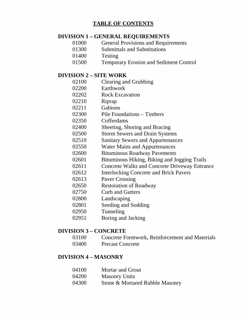
TABLE OF CONTENTS DIVISION 1 – GENERAL REQUIREMENTS
01000 General Provisions and Requirements 01300 Submittals and Substitutions 01400 Testing 01500 Temporary Erosion and Sediment Control
DIVISION 2 – SITE WORK 02100 Clearing and Grubbing 02200 Earthwork 02202 Rock Excavation 02210 Riprap 02211 Gabions 02300 Pile Foundations – Timbers 02350 Cofferdams 02400 Sheeting, Shoring and Bracing 02500 Storm Sewers and Drain Systems 02510 Sanitary Sewers and Appurtenances 02550 Water Mains and Appurtenances 02600 Bituminous Roadway Pavements 02601 Bituminous Hiking, Biking and Jogging Trails 02611 Concrete Walks and Concrete Driveway Entrance 02612 Interlocking Concrete and Brick Pavers 02613 Paver Crossing 02650 Restoration of Roadway 02750 Curb and Gutters 02800 Landscaping 02801 Seeding and Sodding 02950 Tunneling 02951 Boring and Jacking
DIVISION 3 – CONCRETE 03100 Concrete Formwork, Reinforcement and Materials 03400 Precast Concrete
DIVISION 4 – MASONRY 04100 Mortar and Grout 04200 Masonry Units 04300 Stone & Mortared Rubble Masonry
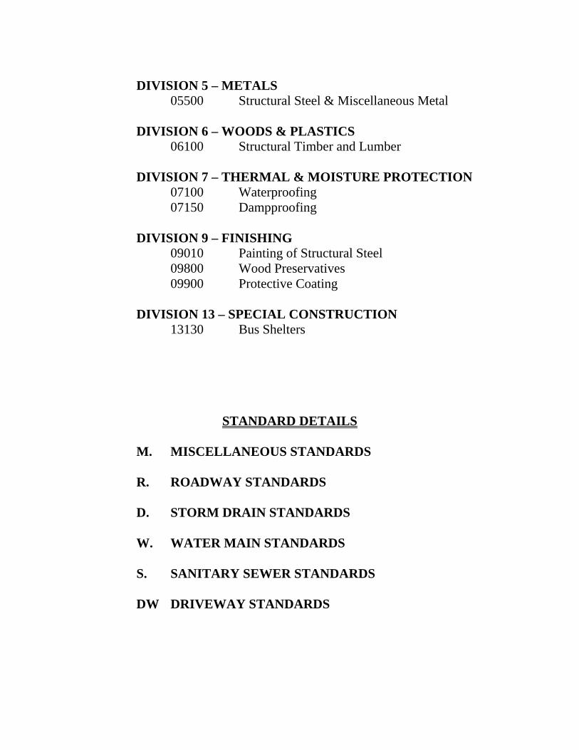
DIVISION 5 – METALS 05500 Structural Steel & Miscellaneous Metal
DIVISION 6 – WOODS & PLASTICS 06100 Structural Timber and Lumber
DIVISION 7 – THERMAL & MOISTURE PROTECTION 07100 Waterproofing 07150 Dampproofing
DIVISION 9 – FINISHING 09010 Painting of Structural Steel 09800 Wood Preservatives 09900 Protective Coating
DIVISION 13 – SPECIAL CONSTRUCTION 13130 Bus Shelters
STANDARD DETAILS
M. MISCELLANEOUS STANDARDS R. ROADWAY STANDARDS D. STORM DRAIN STANDARDS W. WATER MAIN STANDARDS S. SANITARY SEWER STANDARDS DW DRIVEWAY STANDARDS
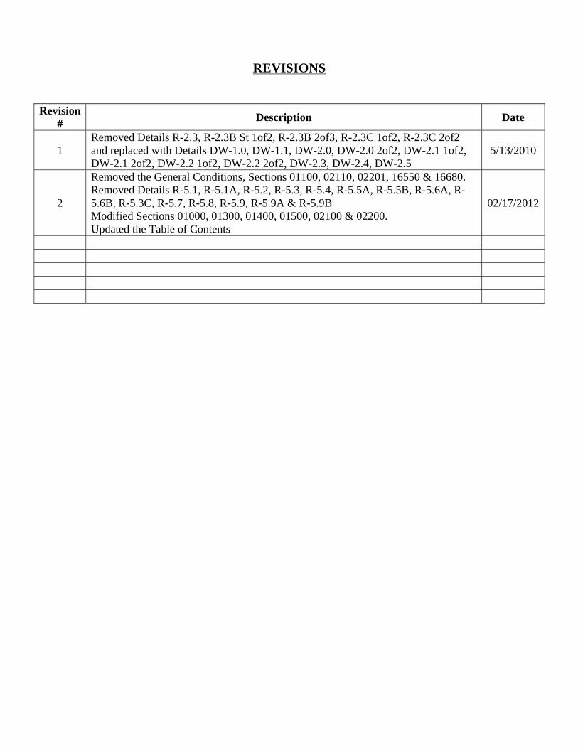
REVISIONS
Revision
# Description Date
1 Removed Details R-2.3, R-2.3B St 1of2, R-2.3B 2of3, R-2.3C 1of2, R-2.3C 2of2 and replaced with Details DW-1.0, DW-1.1, DW-2.0, DW-2.0 2of2, DW-2.1 1of2, DW-2.1 2of2, DW-2.2 1of2, DW-2.2 2of2, DW-2.3, DW-2.4, DW-2.5
5/13/2010
2
Removed the General Conditions, Sections 01100, 02110, 02201, 16550 & 16680. Removed Details R-5.1, R-5.1A, R-5.2, R-5.3, R-5.4, R-5.5A, R-5.5B, R-5.6A, R-5.6B, R-5.3C, R-5.7, R-5.8, R-5.9, R-5.9A & R-5.9B Modified Sections 01000, 01300, 01400, 01500, 02100 & 02200. Updated the Table of Contents
02/17/2012

SECTION 01000 GENERAL PROVSIONS AND REQUIREMENTS
Feb 2012 01000-1
SECTION 01000 - GENERAL PROVISIONS AND REQUIREMENTS
1. Purpose of Section
This section outlines the general provisions and requirements common to these standard specifications and details. This section includes definitions and abbreviations used throughout the specifications and details. All references in this section shall apply to the entirety of these Specifications unless, and except as, explicitly modified in specific sections.
2. Definitions
Wherever used in these Standards and Specifications, the following terms have the meanings indicated which are applicable to both the singular and plural thereof:
BUSINESS DAY – Any day that the County is open for general business.
CALENDAR DAY - Any day of twenty-four hours measured from midnight to the next midnight. Included are weekends and holidays. Where these Specifications do not clarify or distinguish between Calendar Day and Business Day, the reference shall be assumed to indicate a Calendar Day.
CONTRACT - The written agreement (including all attachments and amendments thereto) between OWNER and CONTRACTOR covering the work to be performed. CONTRACT DOCUMENTS – The collection of documents which as a whole comprise the requirements of the Contract or Permit, including any amendments or addendums.
CONTRACT DRAWINGS – The drawings which show the locations, character, dimensions, and details of the Work to be performed under the Contract. CONTRACTOR – The individual, partnership, firm, corporation, limited liability company, joint venture, or other person or entity contracting with the County for performance of prescribed work or holding a PERMIT for work to which these specifications apply. COUNTY – See OWNER
ENGINEER – The Director, Department of Environmental Service, Arlington County, or designee.
OWNER – The County of Arlington, Virginia, for whom the work is to be performed.
PERMIT – Written authorization from the Engineer or other authorizing agency, where applicable, to perform the stipulated work.
PROJECT – The entire construction to be performed as provided in the Contract Documents, Permit, or other relevant construction plans or documents.
PROJECT OFFICER – See ENGINEER
SECTION 01000 GENERAL PROVSIONS AND REQUIREMENTS
Feb 2012 01000-2
PROVIDE – Indicates “provide complete and in place”, that is to “furnish and install”.
ROADWAY- The portion of the right of way used for vehicular, and/or pedestrian travel. SHOP DRAWING – Fabrications, erection and setting drawings, manufacturer’s standard drawings, schedules, descriptive literature, catalogs, brochures, performance and test data, wiring and control diagrams, and all other descriptive data pertaining to the materials and equipment as required to demonstrate compliance with the contract or permit requirements.
SUBCONTRACTOR – Those who have a direct contract with the Contractor or other Subcontractor to perform Work or furnish material worked to a special design according to the Contract Documents. However, the term shall not include those who merely furnish material not so worked.
SUBMITTAL – Any data required by the Contract Documents to be submitted to the Engineer at any point prior to continuing Work. By way of illustration, Submittals would include, but not be limited to: construction schedules, shop drawings, equipment specifications, material samples, and subcontractor or supplier lists.
SUPPLIER - Any person or organization who supplies materials or equipments for the work (including that fabricated to a special design), but who does not perform labor at the site. WORK – The labor, equipment, materials, and all appurtenant items and actions necessary to satisfy the requirements and intent of the contract or permit.
3. Abbreviations
The following is a list of abbreviations used within the technical specifications. The appropriate designation shall refer to the latest edition or update published by that organization:
AASHTO American Association of State Highway and Transportation Officials
ACI American Concrete Institute
AISC American Institute of Steel Construction
ANSI American National Standard Institute
ASTM American Society for Testing and Materials
AWPA American Wood Preservers Association
AWS American Welding Society
AWWA American Water Works Association
SECTION 01000 GENERAL PROVSIONS AND REQUIREMENTS
Feb 2012 01000-3
NFPA National Fire Protection Association
NFPA National Forest Products Association
OSHA Occupational Safety and Health Administration
SSPC Steel Structures Painting Council
VDOT Virginia Department of Transportation
WRI Wire Reinforcement Institute
4. Technical Terms
Materials or work described in words which, so applied, have a well-known technical or trade meaning shall be construed to refer to the technical or trade meaning.
5. Reference to Standards or Specifications
Any material specified by reference to the number, symbol, or title of a specific standard, such as a Commercial Standard, a Federal Specification, a Trade Association Standard, or other similar standard, shall comply with the requirements in the latest revision of the standards or specification and any amendment, or supplement, except as limited to type, class or grade, or as modified in such reference. The standard referred to, except as modified in the contract documents, shall have full force and effect as though printed in the Specifications.
Reference to any article, device, product, material, fixture, form or type of construction by name, make, or catalog number shall be interpreted as establishing a standard of quality and shall not be construed as eliminating from competition other products of equal or better quality by other manufacturers where fully suitable, as determined by the Engineer.
6. Applicable Specifications
The following specifications are incorporated into these standards and specifications by reference. Where the provisions of the referenced specifications conflict with this document, this document shall govern.
Arlington County Traffic Signal & Streetlight Specifications “Manual on Uniform Traffic Control Devices for Streets and Highways” U.S. Department of
Transportation, Federal Highway Administration. The Arlington County Code VDOT Road and Bridge Specifications
7. Applicable Ordinances for Environmental Services and Building Construction
The Contractor or permit holder is responsible for familiarizing himself with the Arlington County Code
SECTION 01000 GENERAL PROVSIONS AND REQUIREMENTS
Feb 2012 01000-4
prior to commencing with any construction. The following codes, in particular, relate to the Environmental Services and building industry:
Chapter 1 General Provisions
Chapter 3 Building Code
Chapter 7 Electrical Code
Chapter 8 Fire Prevention
Chapter 10 Garbage, Refuse and Weeds
Chapter 11 Licenses
Chapter 14 Motor Vehicles and Traffic
Chapter 15 Noise Control
Chapter 18 Plumbing and Gas Codes
Chapter 22 Street Development and Construction
Chapter 23 Subdivisions
Chapter 26 Utilities
Chapter 48 Flood Plain Management
Chapter 55 Underground Utilities Protection
Chapter 57 Erosion and Sediment Control
Chapter 60 Storm water Detention
8. Use of Virginia Department of Transportation Specifications
Virginia Department of Transportation, Road and Bridge Specifications, latest edition, technical specifications only, shall apply and become a part of these specifications whenever these specifications do not adequately cover the work to be done. In the event there is a conflict between these specifications and VDOT Specifications these specifications shall govern.
9. Infeasibility of Specifications
In the event that the Contractor determines that any aspects of the Specifications are infeasible, the Contractor is obligated to immediately notify the Engineer of such infeasibility. If the Engineer agrees
SECTION 01000 GENERAL PROVSIONS AND REQUIREMENTS
Feb 2012 01000-5
that any aspect of the Specifications are in fact rendered infeasible, such determination shall in no way invalidate or otherwise revoke the remainder of the Specifications.
10. Inspection of the Work
The Engineer and representatives of any public authority or public entity shall, at all times, have access to and from the work site during preparation or progress of the work. The Contractor shall provide suitable facilities for such access and for proper observation of the Work and shall conduct all special tests required by the Contract Documents, the Engineer’s instructions, and any laws, ordinances, or regulations of any public entity applicable to the Work.
11. Removal and Disposal of Obstructions
Unless instructed otherwise, the Contractor shall remove existing structures, materials and obstructions, whether explicitly identified in the contract documents or not, which interfere with the new construction at no expense to the County. If such structure, material, or obstruction is unanticipated by the Contract Drawings, the Contractor shall notify the Project Officer prior to disturbance. Structures, materials, artifacts, relics, and other obstructions found on the work site shall be the property of the County. Structures and materials not desired by the County will become the property of the Contractor and shall be disposed of by the Contractor in accordance with all applicable State, Federal, and local regulations. Disposal of such items shall be at no additional expense to the County.
12. Work Site Conditions
The work site shall be kept and maintained by the Contractor in a neat, orderly, and workmanlike appearance at all times. The Contractor shall remove and legally dispose of, as frequently as necessary, all refuse, rubbish, scrap materials and debris generated at the site. At the completion of the work, but before final acceptance by the Engineer, the Contractor shall remove and legally dispose of all surplus materials, false work, temporary structures (including foundations thereof), and debris of every nature resulting from the contractors operations or any activity associated with the work, and restore the site to a neat, orderly condition. If the Contractor, at any time, fails to maintain the site in a neat, orderly, and workmanlike condition, the County shall have the right, upon 24 hours notification, to remove and dispose of such surplus materials, false work, temporary structures, and debris, and put the site in a neat and orderly condition at the Contractor’s expense.
13. Public Convenience
At all times, work shall be conducted so as to ensure the least possible obstruction to traffic and inconvenience to the general public and the properties and residents in the vicinity of the work. No road or street shall be closed to the public except with the specific written permission of the Engineer and the proper governmental authorities. Fire hydrants on or adjacent to the work site shall be kept in operating condition and accessible to firefighting equipment at all times, unless explicitly permitted by the Engineer. Temporary provisions shall be made and provided by the Contractor to ensure the continued use of sidewalks, trails, and transit facilities compliant with all applicable ADA and other regulations.
SECTION 01000 GENERAL PROVSIONS AND REQUIREMENTS
Feb 2012 01000-6
14. Protection of Work and Property
a. The Contractor shall continuously maintain protection of all its Work from damage and shall protect all public and private property from injury or loss arising in connection with this Work. The Contractor shall make good any such damage, injury, or loss, except such as may be caused by agents or employees of the County.
b. The Contractor shall not place upon the Work, or any part thereof, any loads which are not consistent with the safety of that portion of the Work.
c. The Contractor shall be responsible for the preservation of all public and private property, trees, monuments, etc., except those to be removed or abandoned in place and shall protect carefully from disturbance or damage all monuments and property marks until an authorized agent has witnessed or otherwise referenced their location and shall not remove them until directed. Any damage which occurs by reason of the operations under this Work shall be completely repaired by the Contractor at the Contractor's expense.
d. The Contractor shall shore, brace, underpin, secure, and protect, as may be necessary, all foundations and other parts of existing structures adjacent to, adjoining, and in the vicinity of the site that may be affected in any way by excavations or other operations connected with the work embraced in this Work. The Contractor shall be responsible for the giving of any and all required notices to any adjoining or adjacent property owned or other party before commencement of any work. The Contractor shall indemnify and save the County harmless from any damages on account of settlements or loss of all damages for which the County may become liable in consequence of such injury or damage to adjoining and adjacent structures and their premises.
e. In an emergency affecting the safety of life or of the work, or of adjoining property, the Contractor, without special instruction or authorization from the Engineer or County, is hereby permitted to act, at the Contractor's discretion, to prevent such threatened loss or injury, and the Contractor shall so act without appeal, if so instructed or authorized.
15. Accident Prevention
The Contractor shall exercise proper precaution, at all times, for the protection of persons and property and shall be responsible for all damages to persons and property either on or off the site, which occur as a result of the Contractor’s performance of the work. The Contractor shall observe the safety provisions of all applicable laws, including those of the Occupational Safety and Health Administration, and building and construction codes. The Contractor shall take or ensure that such additional safety and health measures are taken as the County may determine to be reasonably necessary. Machinery, equipment, and all hazards shall be guarded in accordance with the safety provisions of the “Manual of Accident Prevention” published by the Associated General Contractors of America, Inc. to the extent that such provisions are not in conflict with applicable local laws. The Contractor shall follow the “Rules and Regulations Governing Construction, Demolition, and all Excavation” as adopted by the Safety Codes Commission of Virginia, 1966, or latest edition, covering requirements for shoring, bracing, and sheet piling of trench excavations.
SECTION 01000 GENERAL PROVSIONS AND REQUIREMENTS
Feb 2012 01000-7
16. Permission to Work on Highways and Across Utilities
When construction shall proceed to cross highways, railroads, or utilities under the jurisdiction of the State, County, or other public agency, public utility, or private entity, the Contractor shall secure written permission, where necessary, from the proper authority before executing such new construction. A copy of such written permission must be filed with the County before any work is started. The Contractor shall furnish to the Engineer a release from the proper authority before final acceptance of the work.
17. Adjacent Work
In case of a dispute arising between two or more contractors engaged on adjacent work as to the respective rights of each under these specifications, the Engineer shall determine the rights of the parties. The Engineer’s decision shall be final and binding on the parties concerned.
18. Connecting Work
The Contractor shall do all cutting, fitting, patching, digging, and other necessary preparations that may be required to make several parts of the work fit properly and/or to receive or be received by the work of other Contractors as shown upon or reasonably implied by the Construction Documents and as directed by the Engineer. The Contractor shall not endanger the integrity of or adversely affect any work by such cutting, fitting, patching, or other preparations. The Contractor shall not alter the work of any other Contractor except with the written consent of the Engineer.

SECTION 01000 GENERAL PROVSIONS AND REQUIREMENTS
Feb 2012 01000-8
SECTION 01300 SUBMITTALS AND SUBMISSIONS
Feb 2012 01300-1
SECTION 01300 SUBMITTALS AND SUBSTITUTIONS
1. Purpose of Section
This section outlines the requirements for submitting and processing the construction schedule, substitutions, shop drawings, samples, and other data which are required for the Engineer’s review for conformance with the standards, specifications and contract documents.
2. Related Requirements Specified Elsewhere
Section 01000 - General Provisions and Requirements
Section 01400 - Testing
3. Submittals – General Requirements
a. The Contractor or permit holder shall not begin work which requires the submission of other data, until said submittals are returned with the Engineer’s initials or signature indicating review and acceptance.
b. After any Submittal has been reviewed by the Engineer, no change will be considered unless satisfactory evidence is presented to prove that the approved Submittal cannot be obtained or that such change is in the County’s best interest.
c. All submittals shall be made so as to cause no delay in the project, allowing reasonable time for review and checking by the Engineer. Except as specified otherwise, all submittals shall be submitted at least ten (10) Business Days before the start of the affected work.
d. Submittals shall be accompanied by all required certifications and other such supporting materials and in such sequence or in such groups that all related items may be checked together.
e. When Submittals cannot be adequately reviewed because a submission is incomplete, does not include all necessary appurtenant submittals, has been submitted out of sequence, is illegible, or for any other reason, the Submittal will be returned by the Engineer without action, or will be held until such materials as are necessary are received. Incomplete or defective submissions as described above shall not be considered to have been submitted.
f. Submittals shall have been reviewed by the Contractor and coordinated with all other related or affected work before they are submitted for approval. If the submittals indicate variations from the Contract Documents because of standard shop practice or other reasons, the Contractor shall make specific mention of such variations in the Contractor’s letter of transmittal such that, if acceptable, suitable action may be taken for proper adjustment. Otherwise, the Contractor will not be relieved of the responsibility of executing the work in accordance with the Contract Documents, even if the Submittal was approved.
g. The Engineer shall review the submittals with reasonable promptness. Review and/or approval of submittals will be general for conformance with the design concept of the project
SECTION 01300 SUBMITTALS AND SUBMISSIONS
Feb 2012 01300-2
and compliance with the information given in the Contract Documents. Approval shall not be construed as permitting any departure from Contract requirements, as authorization of any increase in price, as verification of quantities or field conditions, nor as relieving the Contractor of the responsibility for any error in details, dimensions, or otherwise that may exist.
h. The Contractor shall be responsible for the detailed accuracy of the submittals. Deviations in submittals from the requirements of the Contract Documents or the construction standards shall not be relieved unless the Engineer specifically accepts deviations named in writing by the Contractor.
i. Unless otherwise specified, submit three copies of all submittals.
j. Accompany submittals with a transmittal letter containing the following information:
1. Date
2. Project title and number
3. Contractor’s and supplier’s name and address
4. The number of each shop drawing, product data and sample submitted.
5. Identification of product or material
6. Relation to adjacent structure or material
7. Field dimensions, clearly identified as such
8. Applicable specification section number
9. Applicable standards, such as ASTM number or VDOT specifications.
10. Identification of deviations from Contract Documents
11. Contractor’s stamp, initiated or signed, certifying his review of the submittal, verification of field measurements and compliance with Contract Documents.
4. Construction Schedule
Prior to commencing Work, the Contractor shall submit a Construction Schedule with the following information:
a. Work breakdown structure to a level of detail appropriate to the work such that the Engineer may reasonably monitor and determine at any point whether the Contractor is prosecuting the Work as expected.
b. Task dependencies, durations, early and late starts and finishes.
c. Identification of Critical Path tasks.
SECTION 01300 SUBMITTALS AND SUBMISSIONS
Feb 2012 01300-3
5. Subcontractors
a. Prior to commencing Work, the Contractor shall submit for approval a list of all Subcontractors which are proposed to be used on the Project. The list shall include the following information for each Subcontractor:
1. Name and address of Subcontractor
2. Contact name, title, and phone number
3. Description of the Subcontractor’s qualifications to perform the anticipated Work.
6. Materials & Supplier of Products
Prior to commencing Work, the Contractor shall submit for approval a list of all Suppliers and Products which are proposed for installation. The list shall be tabulated by applicable Specification section or related trades or construction activities.
7. Substitutions
a. The Engineer will consider formal requests for substitution of products in place of those specified up to fifteen Business Days before the start of work.
b. All proposals for substitutions shall be submitted in writing by the General Contractor or permit holder and not by individual trades or material suppliers.
c. Include in the following information in any Substitution request:
1. Complete data substantiating compliance of proposed substitution with Contract Documents.
2. Product identification, including manufacturer’s name, address and literature outlining the product description, performance, test data and reference standards.
3. Samples, if applicable.
4. Name and address of similar projects on which product was used and date of installation.
5. Itemized comparison of proposed substitution with product or method specified including any changes in construction schedule, relation to separate contracts, and accurate cost data on proposed substitution in comparison with product or method specified.
d. If any proposed Substitution will affect any portion of the Project, adjacent construction, work of other Contractors or Subcontractors, or use or functionality of the finished Project, then the necessary changes to or affected functionality of the Project will be considered as an essential part of the proposed Substitution. All such changes or accommodations necessary to restore and/or provide the intended functionality of the Project shall be clearly documented by the Contractor as part of the Submittal.
e. The County will bear no additional expense as a result of any Substitution.
SECTION 01300 SUBMITTALS AND SUBMISSIONS
Feb 2012 01300-4
f. The Engineer will review proposed substitutions and make his recommendations in writing within ten working days. The Contractor shall abide by the Engineer’s recommendations when proposed substitute materials or items of equipment are not accepted for installation and shall furnish the specified material or item of equipment in such case.
8. Shop Drawings
a. Submit drawings, prepared by Contractor, subcontractor, supplier or distributor, which illustrates some portion of the work; showing fabrication, layout, setting or erection details.
b. Identify details by reference to sheet and detail numbers shown on Contract Drawings or the Construction Standards.
c. Use a minimum sheet size of 8 ½ inches x 11 inches.
d. When submitting specific product data, catalog sheets, or the manufacturer’s standard schematic drawings, modify the submissions to delete information which is not applicable to the project. When required, supplement the standard information to provide additional information applicable to project.
e. Show dimensions and clearances required.
f. Show performance characteristics and capacities, where applicable.
g. Note clearly on the drawings any deviations from the material or equipment as specified.
h. The Engineer will review the Shop Drawings with reasonable promptness.
9. Samples
a. Where required, provide physical examples to illustrate materials, equipment or workmanship, and to establish standards by which completed work is to be judged in such quantities and locations as required by the specifications.
b. Samples shall be submitted in single units, unless specified otherwise.
c. Materials and equipment incorporated into the Work shall match the approved Samples.
10. Resubmissions Requirements
If Submittals are disapproved or require revision, revise the initial submittal and resubmit as specified for initial submittal. Indicate on re-submittal any changes which have been made other than those requested by the Engineer.
SECTION 01400 TESTING
Feb 2012 01400-1
SECTION 01400 TESTING
1. Purpose of Section
This section outlines the requirements for submitting and processing the construction schedule, substitutions, shop drawings, samples, and other data which are required for the Engineer’s review for conformance with the standards, specifications and contract documents.
2. Related Requirements Specified Elsewhere
Section 01300 - Submittals
3. General Requirements
a. Materials, supplies, equipment, and work shall be fully tested in accordance with the Contract Documents. Unless otherwise noted within the specification section, perform the type and number of tests called for by the standards referenced.
b. Testing shall be done by an independent testing laboratory approved by the Engineer.
c. Certifications of testing and inspections by the testing laboratory, mills, shops, and factories shall be submitted per Section 01300.
d. The Contractor shall provide the necessary labor and supervision required to support field testing and inspection by the Engineer at no additional cost to the County. Defects disclosed by tests shall be rectified at no additional cost to the County.
4. Measurement and Payments
a. Unless otherwise specified, testing of materials, supplies, equipment, and work to comply with these specifications shall be considered incidental to the work, and the Contractor will not be entitled to further payment. The County may direct additional testing in excess of the Contract requirements at the County’s expense, unless such testing reveals non-compliant work, in which case the Contractor shall bear the cost of the testing.

SECTION 01400 TESTING
Feb 2012 01400-2

SECTION 01500 TEMPORARY EROSION AND SEDIMENT CONTROL
Feb 2012 01500-1
SECTION 01500 TEMPORARY EROSION AND SEDIMENT CONTROL
PART 1 - GENERAL
1. Description of Work
This work shall consist of the application of temporary measures throughout the life of the project to control erosion and siltation. Such measures shall include, but are not limited to, the use of berms, dikes, dams, sediment basins, fiber mats, silt fences, straw bales, washed gravel or crushed stone, mulch, grasses, slope drains, temporary seeding, and other methods. Temporary erosion and siltation control measures as described herein, shall be applied to erodible material exposed by any activity associated with the construction, and consistent with state and local control standards.
2. Related Work Specified Elsewhere
Section 02100- Clearing and Grubbing
Section 02200- Earthwork
3. Applicable Specifications
Erosion and Sediment Control (Chapter 57 of the Arlington County Code)
4. Applicable References
Virginia Soil and Water Conservation Commission Erosion and Sediment Control Handbook.
5. Submittals
Prior to the start of the work the Contractor shall prepare and submit a plan for applying temporary and permanent erosion and siltation control measures. The plan shall include, but is not limited to, the operations of clearing and grubbing, stripping of topsoil, grading, stabilizing cleared areas, dewatering, and the construction of structures at watercourses. Construction work shall not commence until the schedule of work and the methods of operations have been reviewed and approved by the Engineer.
Temporary measures shall be coordinated with the construction of permanent drainage facilities and other contract work to the extent practicable to assure economical, effective, and continuous erosion and sediment control, and to prevent any damage, clogging, or other negative impacts upon the Work or other property.
6. Permits
Unless otherwise specified, the Contractor is responsible for obtaining and complying with any and all applicable State, Federal, and Local permits which are required for construction, including, but not limited to Virginia Water Protection Permits issued by the Virginia DEQ, General Nationwide Permits issued by the US Army Corps of Engineers, and Virginia Stormwater Management Program Permits issued by the Virginia DCR.
SECTION 01500 TEMPORARY EROSION AND SEDIMENT CONTROL
Feb 2012 01500-2
PART 2 - MATERIALS
Materials shall be at the Contractor’s option with the approval of the Engineer in accordance with Arlington County Code, Erosion and Sediment Control Ordinance (Chapter 57).
PART 3 - EXECUTION
7. Installation and Maintenance of Erosion and Sediment Control
a. No grading operations will be allowed until temporary sediment and erosion control measures have been installed in accordance with the approved plan conforming to the requirements of Arlington County Erosion and Sediment Control Ordinance.
b. Control measures shall be periodically cleaned of silt and maintained. Immediately after every rainstorm, all control measures shall be inspected and any deficiencies corrected by the Contractor.
c. The County reserves the right to order the performance of other temporary measures not specifically described herein to correct an erosion or siltation condition.
d. Temporary control measures may be removed when the area has been stabilized.
8. Extent of Grading Operations
a. The Contractor shall limit the surface area of earth material exposed by grubbing, stripping of topsoil and excavation to that which is necessary to perform the next operation within a given area.
b. Unless specifically authorized by the Engineer, the grubbing of root mat and stumps shall be confined to the area over which excavation is to be actively prosecuted within 30 days following the grubbing operations.
c. The stripping of topsoil shall be confined to the area over which excavation is to be actively prosecuted within 15 days following the stripping operations; and excavation and embankment construction shall be confined to the minimum area necessary to accommodate the Contractor’s equipment and work force engaged in the earth moving work.
d. No disturbed area, including stockpiles, is to remain denuded longer than 30 days without temporary seeding or otherwise stabilizing the area.
9. Dewatering and Discharges
a. All dewatering operations shall be conducted in a manner that prevents or minimizes the amount of sediment or other pollutants which discharge to the County storm sewer system, which includes curb and gutter, or any open watercourse. Any discharge from dewatering operations shall be properly filtered prior to being discharged. Dewatering activities shall not create any erosion nor flooding. A dewatering plan must be included as part of the Erosion and Sediment Control plan with sufficient detail to ensure that the proposed dewatering will meet all applicable requirements.
SECTION 01500 TEMPORARY EROSION AND SEDIMENT CONTROL
Feb 2012 01500-3
b. All non-stormwater discharges to the County’s storm sewer system, which includes curb and gutter, or any open watercourse must comply with the conditions of Section A.1.a.3 of the County’s VSMP Municipal Separate Storm Sewer System (MS4) Permit. Contaminants, including but not limited to, volatile organic compounds, petroleum products, metals, PCBs/Pesticides, shall not be discharged to the County’s storm sewer system without approval from Arlington County. A separate Virginia Pollutant Discharge Elimination System (VPDES) permit, issued by DEQ may be required.
c. Contractors shall not dump or dispose of anything in a storm drain, street, stream, or riparian area that could cause adverse conditions. Contractors shall employ good housekeeping and pollution prevention measures at work sites at all times. Work areas, including staging or stockpile areas, shall be kept clean and free of trash and debris to the maximum extent possible. Construction materials shall be properly stored and secured. Stockpiled materials shall be kept covered and perimeter controls shall be employed to minimize exposure to wind, precipitation, and runoff. Equipment and vehicle washing shall not be permitted on-site without proper controls and facilities to collect all sediment and/or pollutants. Spill kits and appropriate tools for cleanup shall be kept on-site at all times. Spills shall be cleaned immediately using absorbent materials or other appropriate measures which will prevent any pollutants from entering a storm drain or open watercourse.
PART 4 - MEASUREMENT AND PAYMENT
10. Measurement and Payment
a. Unless otherwise specified, no separate measurement of quantities will be made for this work. Temporary erosion and sediment control as detailed on the approved plan is considered to be a subsidiary obligation to the Contract and therefore, there will be no payment made for this work.
b. No measurement will be made for temporary erosion control required to correct conditions created due to the Contractor’s negligence, carelessness or failure to install permanent controls in accordance with the approved plan, or methods or sequence of such work.
c. No measurement will be made for limiting the area of construction operations as directed by the Engineer. The cost of shaping the top of earthwork, constructing temporary earth berms, slope drains, straw bales, etc., considered being a subsidiary obligation to the Contract and therefore, there will be no payment made for this work.
d. In the event the Contractor repeatedly fails to satisfactorily control erosion and siltation, the Owner reserves the right to employ outside assistance or to use its own forces to provide the corrective measures indicated; the cost of such work, plus engineering costs, will be deducted from monies due to the Contractor for other work.

SECTION 01500 TEMPORARY EROSION AND SEDIMENT CONTROL
Feb 2012 01500-4
SECTION 02100 CLEARING AND GRUBBING
Feb 2012 02100-1
SECTION 02100 CLEARING AND GRUBBING
PART 1 - GENERAL
1. Description of Work
Provide all labor, material and equipment to perform all clearing and grubbing as called for on the approved plans and as specified herein, or as necessary to prosecute the Work.
2. Related Work Specified Elsewhere
Section 01500 – Temporary Erosion and Sediment Control
Section 02200- Earthwork
3. Applicable Specifications
Erosion and Sediment Control Ordinance (Chapter 57 of the Arlington County Code)
Garbage, Refuse and Weeds Code (Chapter 10 of the Arlington County Code)
American Association of Nurserymen (A.A.N.)
International Society of Arboriculture (I.S.A.) National Arborist Association (N.A.N.)
4. Protection of Vegetation
a. Protect existing trees, shrubs and bushes outside the limits of clearing and grubbing by fencing or barricading as required by the Urban Forester (DPRCR). Protect existing trees designated to be saved inside the limits of clearing and grubbing by methods approved by the Urban Forester (DPRCR), which may include tree protection fencing, root pruning, and/or protective matting.
b. Trees damaged by construction operations shall be evaluated by the Urban Forester (DPRCR) and replaced, pruned, and/or treated. Pruning or treatment must be performed by an International Society of Arboriculture (I.S.A) Certified Arborist.
c. Replace trees damaged beyond repair by the construction process with nursery grown stock meeting American Association of Nurserymen (A.A.N.) Standards. Trees shall be replaced per the County’s tree replacement guidelines.
5. Protection of Property
a. Protect property pipes, stones and monuments from damage. The Contractor will be responsible for replacing disturbed markers by a registered surveyor at no expense to the County.
SECTION 02100 CLEARING AND GRUBBING
Feb 2012 02100-2
b. Protect street, roads, historical objects, adjacent property, vegetation and other works to remain throughout the contract.
PART 2 - MATERIALS
PART 3 - EXECUTION
6. Clearing
The area of clearing shall be maintained within the limits shown on the plans. Individual trees, groups of trees and other vegetations, which are to remain within the areas to be cleared, are to be undisturbed, standing and not injured. Tree protection boundaries will be established and secured as directed by the Urban Forester (DPRCR) to protect the root systems as well as above ground trees. The tree protection area shall not be violated.
7. Grubbing
The area of grubbing shall be maintained within the clearing limits shown on the plans. Remove stumps and matted roots to a depth of 24 inches below existing ground surface. Refill excavations made by removal of stumps or roots as specified for backfill in Section 02200.
8. Trimming of Trees
a. Trees may be trimmed to remove branches or roots which interfere with construction when so approved by the Engineer and Urban Forester (DPRCR). All trimming and pruning shall conform to specifications and standards of practice of the National Arborist Association.
b. Do not unnecessarily cut tree roots extending into grading limits. When roots are exposed by the work, cut them back cleanly with hand pruning shears, lopping shears or hand saws, and backfill with approved topsoil immediately. Backfill around tree roots immediately after completion of construction in vicinity of the trees. Backfill around trees and roots shall be compacted to no more than 80% unless otherwise directed by the Engineer.
9. Salvage
a. Unless otherwise indicated on the plans, remove only those trees which directly interfere with the construction of the project. Trees designated by the Engineer to be salvaged shall be either mechanically dug with a tree spade or hand dug, balled and burlapped with root ball sizes as specified by the American Association of Nurserymen.
b. Material which is to be salvaged, as a result of clearing operations, shall include live plants suitable for replanting. Shrubbery is to be transplanted as trees using A.A.N. Standards. If required, temporarily replant the shrub and at the completion of construction replace according to A.A.N. Standards.
c. Place any desirable topsoil in well-drained stockpiles, not to exceed 7 feet in height, and protect per Section 01500
SECTION 02100 CLEARING AND GRUBBING
Feb 2012 02100-3
10. Disposal
a. Dispose of trees and shrubs in accordance with the Garbage, Refuse and Weeds Ordinance of the Arlington County Code. When approved by the Engineer, material may be dumped within the Contract area where directed.
b. Do not burn materials on the site. The County Fire Marshal may consider granting a waiver from open burning restrictions in cases where the State Air Pollution Control Board has granted a waiver to the Contractor or permit holder. The responsibility for obtaining all waivers shall be the Contractor’s or permit holders.
c. Remove material from the site as it accumulates. Do not allow waste material to accumulate for more than 48 hours.
PART 4 - MEASUREMENT AND PAYMENT
No separate measurement of quantities will be made for this work. Clearing and grubbing is considered to be a subsidiary obligation of the contract and, therefore, there will be no payment made for this work.

SECTION 02100 CLEARING AND GRUBBING
Feb 2012 02100-4
SECTION 02200 EARTHWORK
Feb 2012 02200-1
SECTION 02200 EARTHWORK
PART 1 - GENERAL
1. Description of Work
Provide all labor, material and equipment to perform all excavation, transportation, handling, disposal, placement, shaping, compaction, and other tasks pertaining to earthwork for the structures, pipelines, roadways, and other work as called for on the approved plans and as specified herein.
2. Related Work Specified Elsewhere
Section 01500 – Temporary Erosion & Sediment Control
Section 02100 - Clearing and Grubbing
Section 02202 - Rock Excavation
Section 02400 - Sheeting, Shoring and Bracing
Section 02650 - Restoration of Roadway
3. Applicable Specifications
a. American Association of State Highway and Transportation Officials (AASHTO)
b. American Society for Testing and Materials (ASTM)
c. Occupational Safety and Health Act, State & Federal (OSHA)
d. Underground Utility Protection Ordinance (Chapter 55 of the Arlington County Code)
e. Erosion and Sediment Control Ordinance (Chapter 57 of the Arlington County Code)
f. Virginia Department of Transportation, Road and Bridge Specifications (VDOT)
4. Underground Utilities
The location of existing utilities has been indicated on the drawings based on the best information available. The completeness or accuracy of the information is not guaranteed. Contractor shall notify “Miss Utility” in accordance with the provisions stipulated in the Underground Utility Protection Ordinance (Chapter 55), of the Arlington County Code.
5. Overhead Utilities
The Contractor shall identify and protect all existing overhead utility poles and facilities in the vicinity of the Work. The Contractor will be solely responsible for all necessary notification and coordination
SECTION 02200 EARTHWORK
Feb 2012 02200-2
with the utility owner(s). There will be no payment made for necessary bracing, sheeting, shoring, or other work required to protect and maintain existing utility poles or overhead utilities.
6. Existing Foundations
When foundations are located such that excavation may endanger or interfere with an existing structure or utility, the Contractor shall take all measures necessary to protect the existing utilities or structures. There will be no payment made for these measures.
7. Stability of Excavations
The Contractor shall be solely responsible for the stability of excavations and for meeting all State and Federal OSHA requirements. Provide all sheathing, lagging, bracing, and other support required to retain the stability of excavations.
8. Care and Restoration of Pavement and Property
When excavations are to be made in paved surfaces, the Contractor shall sawcut or use of a similar tool so as to provide a clean, uniform edge with a minimum of disturbance to remaining pavement. Pavement and other property outside of the defined Limits of Disturbance shall be preserved in the condition existent prior to construction. Damage or other impacts upon pavement or property outside the Limits of Disturbance shall be restored immediately at the Contractor’s expense.
9. Construction Tolerance
Compact, shape, slope, and dress to yield the grades and slopes illustrated on the approved plans. In backfilled or other non-paved areas, grades shall be within 0.10 foot of the design grade. Slopes shall not be steeper than 2(H):1(V) and shall not deviate from a theoretical plane surface by more than 0.5 feet.
PART 2 - MATERIALS
10. Backfill
Backfill shall be free of vegetation, masses of roots, and stones over 3-inches in any dimension, frozen material, cinders, ashes, refuse, or porous matter. Organic matter shall not exceed minor quantities and shall be well distributed. In addition, Backfill shall be of such a nature and in such condition that it can be compacted to a dense and stable fill.
11. Topsoil
a. Topsoil furnished by the Contractor shall consist of a natural friable surface soil without admixtures of subsoil, refuse, or foreign materials. It shall be reasonably free from roots, hard clay, coarse gravel, stones larger than 2 inches in any dimension, noxious weeds (including quackgrass rhizomes and the nut-like tubers of nutsedge), tall grass, brush, sticks, stubble, or other materials which would be detrimental to the proper development of vegetative growth.
SECTION 02200 EARTHWORK
Feb 2012 02200-3
b. Topsoil shall contain not less than 3% nor more than 10% organic matter by weight.
c. The Contractor shall Submit per Section 01300 to the Project Officer a soil analysis describing the soil composition including pH factor and percentage of organic content prior to placing any Topsoil.
12. Select Borrow
Select Borrow shall conform to VDOT Section 207 – Select Material, Type I.
13. Inspection of Materials
The Project Officer shall determine the feasibility or suitability of soils based upon testing provided by the Contractor and any other relevant information. The Project Officer’s decision shall be final.
PART 3 - EXECUTION
14. Location & Protection of Existing Structures & Utilities
a. Locate all utility pipes, conduits and facilities well ahead of the excavation process. Plainly mark all such locations and comply with the Underground Utility Protection Ordinance (Chapter 55), of the Arlington County Code.
b. Where the Contractor has identified or anticipates existing utilities, structures, or artifacts, excavate using hand tools or other labor intensive activity as necessary to protect the facilities. No extra compensation or time will be allowed for this activity
c. In case of damage caused by the Work, notify the owner or appropriate agency or party and affect repair in a manner resulting in a condition at least equal to the condition prior to construction. No extra compensation or time will be allowed for repair of damages.
15. Trench Excavation
a. Carry out the excavation, dewatering, sheeting, and bracing in such manner as to eliminate any possibility of undermining or disturbing the foundations of any existing structure, utility, facility, or any work previously completed.
b. Excavate pipe trenches to the necessary depth as shown on the drawings, holding the width below top of pipe as shown in the Standard Details.
c. The Contractor shall comply with all OSHA and/or other applicable regulations for excavation.
d. Excavate trenches to provide a uniform and continuous bearing and support for the pipe and appurtenant structures on solid and undisturbed ground and at the specified grade at every point.
e. Correct any part of the trench bottom excavated below the specified grade with approved materials and thoroughly compact. Shape the bottom of all pipeline trenches to fit the lower
SECTION 02200 EARTHWORK
Feb 2012 02200-4
part of the pipe exterior for a width of a least 60% of the pipe breadth. Shape the excavation and/or bedding for pipe bells, joints, and fittings. Care shall be taken that stones and lumps shall not become nested.
f. Should an unacceptable bedding for the proposed pipe or structure be encountered, notify the Engineer. The Engineer may direct additional excavation below the bottom of the proposed pipe or structure and direct the contractor to provide an alternate bedding or foundation. Additional excavation due to the fault or negligence of the Contractor or without prior approval from the Engineer shall be remedied at the expense of the Contractor.
16. Sheeting, Shoring, and Bracing
Provide sheeting, shoring and bracing in accordance with Section 02400.
17. Storage, Handling, and Disposal of Excavated Materials
a. Carefully remove loam and topsoil to be incorporated in the finished work and store separate from the other excavated material. Failure to isolate loam and topsoil from the other excavations shall require that said soils not be used as topsoil.
b. Excavation shall include the disposal of material deemed unsuitable by the Project Officer for reuse in the Work. The Contractor shall stockpile, treat, and/or otherwise manipulate suitable materials which may be incorporated into the project at a later date or different location. The Contractor is responsible for protecting any stockpiled material from contamination by unsuitable material and from degradation by any other means. Failure by the Contractor to adequately handle and protect excavated material will result in the Contractor being directed to use Select Borrow or other approved material at no expense to the County. Unless otherwise specified, the Contractor will be solely responsible for securing the necessary area for stockpiling, treating, protecting, and related activities.
c. Do not mix pavement with other excavated material. Dispose of excavated pavement away from the work site immediately. All costs associated with removing, handling, transporting, disposing, etc. of existing pavement, curb and gutter, sidewalks, driveway aprons, etc. is considered to be incidental to Excavation and no additional compensation will be considered for such activities.
d. All materials deemed unsuitable for use in the Work by the Project Officer shall be disposed of by the Contractor at his own expense. Storing, transporting, loading, handling, treating, and other associated costs are considered to be incidental to the Work and no additional compensation will be considered for such activities.
e. The County shall take preference over others in claiming excavated material. The Contractor shall consult the Engineer before disposing of such materials.
f. If space is available at the County’s Trades Center, the Contractor may be directed to dispose of clean excavated asphalt and/or unreinforced concrete pavement there, at no cost to the Contractor or the County. If space is not available at the Trades Center, the Contractor will be responsible for alternate disposal arrangements. No additional compensation will be made
SECTION 02200 EARTHWORK
Feb 2012 02200-5
if the Trades Center does not have adequate space to accommodate materials from the project.
18. Dewatering
At all times during construction – provide, place and maintain ample means and devices with which to remove promptly all water entering trenches and other excavations. Keep excavations dry until the structures, pipes, and appurtenances to be built therein have been completed and backfilled. Dispose of all water pumped or drained from the work without impact to the Work, traffic, or injury to public or private property, and in compliance with all Local, State, and Federal regulations.
19. Backfilling – General
a. If the Project Officer determines that sufficient approved material from excavation on the job-site is not available for backfill, the Contractor shall secure material from areas outside the job-site to complete the backfill.
b. All backfill materials shall contain sufficient moisture for proper compaction.
c. Except in proposed landscape areas, or where otherwise specified, each layer of material shall be compacted to a dry density not less than 95 percent of the maximum determined by the Modified Proctor Compaction Test. Upon completion of backfilling in any area under the contract, the Owner may make tests to determine the degree of compaction of the backfill material. If the results of test indicate densities less than specified, the Contractor shall, at his own expense, remedy the condition as directed, in such portions of the trenches as may be required.
d. Backfill all excavations as rapidly as practicable after the completion of each section of the work. All unauthorized excavations made by the Contractor shall be immediately backfilled at the Contractor’s expense. Complete all backfilling to the dimensions and levels shown on the drawings.
e. The placement of material around structures shall be carried out symmetrically around the structure in horizontal lifts not to exceed six inches of loose material. The Contractor shall protect, and be responsible for any damages to adjacent structures or utilities.
f. Start backfilling around concrete structures only after the concrete has reached sufficient strength to withstand the pressure exerted by the material and compacting equipment and after carrying out and satisfactorily completing the tests specified in Section 03100, Concrete Formwork, Reinforcement and Materials.
g. At points which cannot be reached by mobile mechanical equipment, use suitable power-driven tampers to achieve the same degree of compaction.
h. No material shall be placed or compacted when it is wet or frozen or when the sub grade or previously placed material is wet or frozen.
SECTION 02200 EARTHWORK
Feb 2012 02200-6
20. Backfill for Pipelines
a. The sub grade shall be properly shaped before any material is placed and compacted. Care shall be taken that stones and lumps shall not become nested.
b. Place backfill material in six-inch layers to a point at least two feet above the pipe crown. Thoroughly compact each layer for the full trench width and under, around, and over the pipe, using hand-operated mechanical tampers exerting a pressure of not less than 250 foot pounds per square foot of tamping force. The contractor will be responsible for pipe damage as a result of excessive tamping force.
c. Remainder of trench, more than two feet above pipe crown, may be backfilled by machinery in one-foot layers, thoroughly compacted.
21. Final Grading & Topsoil
a. Prior to placement of topsoil, the subgrade shall be disced or rototilled to a minimum depth of 2 inches.
b. Topsoil shall be uniformly distributed in a 4-8 inch layer and lightly compacted to a thickness of 4 inches (or as indicated on the plans) using a cultipacker, roller, or other approved equipment weighing 100-160 pounds per linear foot of roller.
c. Topsoil shall not be placed when either the topsoil or the subgrade is frozen, excessively wet, extremely dry, or in a condition otherwise detrimental to proper grading.
d. Final grading shall not permit ponding of water.
22. Tests and Testing
a. The optimum moisture content and the maximum density of each type of material used for structural fill and backfill shall be determined by “Standard Test Methods for Moisture Density Relations of Soils and Oil- Aggregate Mixtures Using 5.5-lb. Rammer and 12-inch Drop (ASTM D698) or (AASHTO T-99)”.
b. The field moisture content of materials being compacted shall be determined by “Laboratory Determination of Moisture Content of Soil,” (ASTM D2216). The field density of compacted material shall be determined by either “Standard Test Method for Density of Soil in Place by Sand Cone Method,” (ASTM D1556) or- “Standard Test Method for Density of Soil in Place by the Rubber Balloon Method,” (ASTM D2167).
c. Perform sufficient field density and field moisture content tests on each lift of material to ensure the Engineer that the requirements of this Section of the Specifications are compiled with.
d. State when and where the tests are to be made so that the Engineer may observe the testing. Submit certified reports verifying test results. The Engineer may order more testing should he feel the above procedures to give inadequate information, or if he feels the results of such testing to be questionable.
SECTION 02200 EARTHWORK
Feb 2012 02200-7
23. Maintenance of Backfilled Excavations
a. The Contractor shall maintain the backfilled area in proper condition for a period of one year after final acceptance of the project. All defects shall be promptly corrected. If the Contractor fails to do so within a reasonable time after the receipt of written notice from the Engineer, the County may correct any dangerous condition at the Contractor’s expense.
b. The Contractor shall be responsible for any injury or damage that may result from improper maintenance of trenches at any time previous to the end of the aforementioned guarantee period.
24. Fill or Embankments
a. Fill or embankment above existing grade shall consist of the placing, shaping, and compaction of approved Backfill material as illustrated on the approved plans.
b. Concrete foundations, slabs, rocks, boulders, and similar material removed during excavation may be utilized in embankments when said material will be located five feet or more below the proposed subgrade surface. When such materials are used, they shall be fractured into pieces such that no dimension exceeds 18 inches in any dimension or plane. The Contractor shall take care to ensure that no voids develop, and will be held responsible for any surface settlement resulting there from.
c. The embankment material shall be uniformly compacted throughout in lifts of no more than 12 inches, except in the case of rock, where lifts of up to 2 feet may be used. Except as otherwise allowed in the paragraph above, the embankment material shall conform to the requirements of Backfill. Each layer shall be compacted at optimum moisture content and the embankment shall have the required maximum density of ninety five percent (95%) as compared to the density of the same material when tested in accordance with AASHTO T-99.
d. Do not place embankment upon frozen ground or areas covered with snow or ice or saturated soils.
e. The area upon which embankments are to be placed shall be denuded of vegetation per Section 02100.
f. Compact the ground upon which the embankment will be constructed to a depth of 8 inches prior to placing any fill material.
g. Embankments to be constructed over swampy areas may be deposited by end dumping the original course. This course may exceed 8”, but shall be the minimum depth required to support the equipment and shall be determined by the Engineer. The use of compaction equipment will not be required on the original course.
SECTION 02200 EARTHWORK
Feb 2012 02200-8
PART 4 - MEASUREMENT AND PAYMENT
25. Excavation
When explicitly included as a pay item, Excavation will be measured by the cubic yard as illustrated on the approved plans, or as approved by the Project Officer. Excavation in excess of that shown on the approved plans will not be compensated, unless specifically approved in advance by the Project Officer. Payment will include all labor, materials, and equipment and will include excavation, handling, storage and disposal of materials, backfilling, compaction, testing, and all other activities necessary to comply with these Specifications.
26. Fill
When explicitly included as a pay item, Fill will be measured by the cubic yard in place as illustrated on the approved plans, or as approved by the project Officer, and will include all materials, equipment, and labor to construct the fills or embankments as illustrated on the construction drawings. Unless otherwise specified, Backfilling of excavations will not be compensated as Fill. Payment will include all clearing and grubbing, preparation, acquisition, transporting, storing, and handling of material, placement, shaping, compaction, and other activities necessary to comply with these Specifications.
27. Over excavation
When included as a pay item or Stipulated Price Item, and authorized by the Project Officer, Over Excavation conducted as a result of obstructions or unsuitable bedding for pipes or structures shall be measured in cubic yards excavated in excess of the contract documents. Payment shall be made for cubic yards and will include excavation, handling, storage and disposal of materials, backfilling, compaction, testing, and all other activities necessary to comply with these Specifications. When not included as a pay item or Stipulated Price Item, Over Excavation will be paid as Excavation. No payment shall be made for any Over Excavation unless ordered in writing by the Engineer prior to commencement of the operations.
28. Select Borrow
When included as a pay item or Stipulated Price Item, and authorized by the Project Officer, Select Borrow shall be measured in cubic yards in place. Payment will include acquisition of materials, transport, preparation, handling, storage, placement, compaction, testing, and other activities necessary to comply with these Specifications
29. Protection of Existing Utilities, Structures, and Property
Protection of existing utilities (above and below ground), structures, and other property is considered a subsidiary obligation of the Work. There will be no compensation or other consideration for the protection, repair, replacement, or restoration of any such facilities. In the event of unknown and unidentified underground utilities or other underground structures that must be protected to complete the Work, the Contractor shall immediately notify the Engineer. The Contractor shall identify appropriate methods to protect the unidentified facilities, and any compensation deemed due, and shall obtain approval from the Engineer prior to undertaking any action.

SECTION 02200 EARTHWORK
Feb 2012 02200-9
30. Testing
Testing will be considered subsidiary to the Work and no compensation will be approved. If the Project Officer directs testing in excess of that required by the Contract Documents, the Contractor shall be entitled to compensation unless such testing reveals noncompliant work

SECTION 02200 EARTHWORK
Feb 2012 02200-10
SECTION 02202 ROCK EXCAVATION
05/2005 02202-1
PART 1 - GENERAL
1.1 Description of Work
Provide all labor, materials, tools and equipment as required to excavate and dispose of rock as specified herein.
1.2 Related Work Specified Elsewhere
Section 02200 - Earthwork for Structures and Pipelines Section 02201 - Earthwork for Roadways
1.3 Applicable Specifications
Underground Utility Protection Ordinance (Chapter 55 of the Arlington County Code)
1.4 Submittals
Submit the blasting plan to the Engineer for review and acceptance. Keep and submit to the Engineer an accurate record of each blast. The record shall show the general location of the blast, the depth and number of drill holes, the kind and quantity of explosive used, and other data required for a complete record.
1.5 Definition:
Rock shall be defined as:
1. Boulders or concrete material, excluding curb and gutter and sidewalk,
exceeding 1/2 cubic yard in volume.
2. Solid ledge rock conglomerate deposits and non-stratified masses so firmly cemented as to require drilling and blasting; wedging; and/or barring for its removal.
1.6 Permits and Regulations
A. Obtain all permits required for the transportation, handling, storage and use of explosives and drilling equipment. Blasting permits shall be obtained from the Arlington County Fire Marshal.
B. Observe the Underground Utility Protection Ordinance of Arlington County as
well as state and federal laws and ordinances relating to explosives. Blasters shall have licenses available for examination at all times on the work site.
SECTION 02202 ROCK EXCAVATION
05/2005 02202-2
PART 2 - MATERIALS
Explosives shall be commercial grade. Explosives, equipment and appurtenant items are the Contractor's option.
PART 3 - EXECUTION
3.1 General
Excavate rock to the lines and grades indicated on the construction standards. Excavate to 6 inches below pipe or precast structure bottom and to the bottom of poured-in-place concrete structures.
3.2 Explosives
When the use of explosives is necessary, exercise the utmost care not to endanger life or property. Be responsible for damage resulting from the use of explosives. The Engineer shall not be responsible for the blasting plan.
3.3 Blasting
A. Notify the Engineer at least 48 hours in advance of blasting operations.
B. Conduct all operations involving explosives using experienced personnel only.
C. Blast only with such quantities and strengths of explosives and in such manner
as will break the rock approximately to the intended lines and grades.
D. Avoid excessive cracking of the rock upon or against which any structure will be built. Prevent damage to existing pipes or other structures and property above or below ground.
E. Cover areas to be blasted with mats, logs or other material to stop flying
matter during explosions. Give sufficient warning to all persons in the vicinity of the work before a charge is exploded. Employ flagmen to stop or direct traffic as required.
3.4 Excess Rock Excavation
If rock is excavated beyond the limits of excavation indicated on the standard and is not authorized in writing by the Engineer, the excess excavation, whether resulting from over breakage or other causes, shall be defined as excess rock excavation and backfilled, by and at the expense of the Contractor, as specified below:
1. In pipe trenches, excess excavation below the elevation of the bottom of the pipe bedding, cradle or encasement shall be filled with material of the same
SECTION 02202 ROCK EXCAVATION
05/2005 02202-3
type, placed and compacted in the same manner, as specified for the bedding, cradle, or encasement.
2. In excavations for structures, excess rock excavation beneath foundations shall be filled with Class A3 concrete. Other excess rock excavations shall be filled with structural fill as specified in Section 02200 with the approval of the Engineer.
3. In excavations for roadways, excess rock excavation shall be filled with material as specified for the sub grade.
3.5 Shattered Rock
If rock below normal depth is shattered due to drilling or blasting operations and such shattered rock is unfit for foundations, the shattered rock shall be removed and the excavation shall be backfilled as described above in excess rock excavation. All such removal and backfilling shall be classified as excess rock excavation and shall be at no additional expense to the County.
PART 4 - MEASUREMENT AND PAYMENT
4.1 The measurement for rock excavation for structures and pipelines shall be the vertical depth up to 6 inches below pipe and precast structures and to the bottom of cast-in-place structures. The pay width for rock shall be as shown in the pipe trench standards for pipe and shall be the outside dimension plus 12 inches for structures. The pay width and depth shall be fixed regardless of the actual dimensions of rock excavation. Payment shall be made for the cubic yards excavated and shall include the pipe or precast structure bedding due to over excavation. Any additional testing required, including seismograph, other than that shown on approved plans shall be done at no cost to the County.
4.2 The measurement for rock excavation for roadways shall be to the bottom of the sub grade and to the lines and grades as shown on the approved plans. Payment shall be made for the cubic yards excavated.

SECTION 02210 RIPRAP
05/2005 02210-1
PART 1 - GENERAL
1.1 Description of Work
Provide all labor, material, equipment and incidentals to furnish and place the riprap as called for on the approved plans and as specified herein.
1.2 Related Work Specified Elsewhere
Section 03100 - Concrete Formwork, Reinforcement and Materials Section 04100 - Mortar and Grout
1.3 Applicable Specifications
Virginia Department of Transportation, Road and Bridge Specifications (VDOT)
PART 2 - MATERIALS
2.1 General
A. Stone for riprap and bedding shall be as specified in VDOT Section 205 and
shall be sound, durable and free from seams, cracks and other structural defects or imperfections tending to destroy its resistance to weathering.
B. Riprap bedding shall be reasonably well graded crush stone within the
following limits:
Sieve Size
Total Percent Passing
3-inch
1-1/2-inch
3/4-inch
No. 4
No. 16
No. 50
100
75-95
50-85
25-55
10-25
2-10
C. Grade A, B, or C sand may be used in mortared or grouted riprap.
2.2 Dry Riprap
A. Dry riprap, Class I, shall meet VDOT Section 414.03(a).
B. Dry riprap, Class II, shall meet VDOT Section 414.03(a).
C. Dry riprap, Class III, shall meet VDOT Section 414.03(a).
SECTION 02210 RIPRAP
05/2005 02210-2
2.3 Mortared Riprap
Stone for this purpose shall as far as practicable, be selected as to size and shape in order to secure fairly large, flat-surfaced stone which will produce a nearly true and even surface with a minimum of voids. Place the stone upon a slope not steeper than the natural angle of repose of the fill material. Fifty percent of the mass shall be broad flat stones, 2 cubic feet or more in volume, laid with the flat surface uppermost and parallel to the slope. Mortar mix shall conform to the requirements of Section 04100.
2.4 Grouted Riprap
Grout for grouted riprap shall consist of one part of Portland cement and three parts of sand, thoroughly mixed with water to produce grout having a thick, creamy consistency. The stones shall be of the same sizes and placed in the same manner as specified for dry riprap, Class 1.
2.5 Stone Riprap
Stone riprap for pier and abutment protection shall range in size up to derrick stone and shall be graded from coarse to fine in such a manner as to provide a minimum of voids.
2.6 Concrete Slab Riprap
The concrete slabs for riprap shall consist of Class A concrete, cast-in-place 6 inches thick, unless otherwise noted on the approved plans. The slabs shall be of two types: plain or reinforced concrete. If reinforcement is required, it shall be furnished as shown on the approved plans.
2.7 Dumped Riprap
A. Type (1) Core Riprap: Core riprap shall conform to the general requirements of
this section and shall be reasonably well graded. It shall be composed of compact, angular pieces of derrick stone weighing no less than 500 pounds and no more than 4,000 pounds each, averaging 2,000 pounds, except that approximately ten percent by weight may consist of pieces weighing from 10 to 250 pounds each. Neither the width nor thickness of any piece of riprap shall be less than one-third of its length.
B. Type (2), Heavy Riprap: Heavy riprap shall conform to the general
requirements of this section and shall be reasonably well graded. It shall be composed of compact, angular pieces of derrick stone weighing no less than three tons and no more than ten tons each, averaging four tons. Neither the width nor thickness on any piece of riprap shall be less than one-third of its length.
SECTION 02210 RIPRAP
05/2005 02210-3
PART 3 - EXECUTION
3.1 Riprap Bedding
Riprap bedding of the thickness indicated on the plans shall be placed on the embankment to form a backing for the riprap. Where approved by the Engineer a construction fabric or matting may be substituted for backing, as shown on the approved plans. Spread riprap bedding uniformly on the prepared base, in a satisfactory manner, to the lines indicated on the approved plans or as directed. Placing of material by methods which will tend to segregate particle sizes within the bedding base during placing of bedding shall be repaired before proceeding with the work. Compaction of the bedding material will not be required, but it shall be finished to present a reasonably even surface free from mounds or depressions.
3.2 Dry Riprap
a. Place the stones upon a slope not steeper than the natural angle of repose of the
fill material. Lay with joints as close as practicable and lay the courses from the bottom of the bank upward, the larger stones being placed in the lower courses. Fill the open joints with spall.
b. For Class 2 and Class 3 riprap, use stones having one broad flat surface when
possible, and lay the flat surface on a horizontal earth bed prepared for it and so placed as to overlap the underlying course, the intent being to secure a lapped or – “shingled” surface which will shed a maximum amount of water. Fifty percent of the mass shall be of stones having a volume of two cubic feet or more. These stones shall be placed first and roughly arranged in close contact. Then fill the spaces between the larger stones with stone of suitable size so placed as to leave the surface evenly stepped, conforming to the contour required, and capable of shedding water to the maximum degree practically attainable.
3.3 Mortared Riprap
Place these stones first and roughly arranged in close contact, the largest stones being placed near the base of the slope. Fill the spaces between larger stones with stones of suitable size, leaving the surface reasonably smooth and tight and conforming to the contour required. In general, lay the stone with a degree of care that will ensure for plane surfaces a maximum variation from a true plane of not more than 1-1/2 inches in four feet. Warped and curved surfaces shall have the same general degree of accuracy as specified for plane surfaces.
As each of the larger stones is placed, surround it by fresh mortar and shove adjacent stones into contact. After the larger stones are in place, fill all the spaces or openings between them with mortar, and place the smaller stones by shoving them into position, forcing excess mortar to the surface, ensuring that each stone is carefully and firmly bedded laterally.
After the work has been completed as described, all excess mortar forced up shall be spread uniformly to completely fill the surface voids. Point all surface joints roughly with flush joints or with shallow, smooth-raked joints.
SECTION 02210 RIPRAP
05/2005 02210-4
3.4 Grouted Riprap
Care is to be taken during placing to keep earth or sand from filling the spaces between the stones. After the stones are in place, completely fill the spaces between them with grout from bottom to top and sweep the surface with a stiff broom. Do not grout riprap in freezing weather.
In hot, dry weather, protect the work from the sun and keep moist for at least three days after grouting by the use of saturated burlap.
3.5 Stone Riprap for Foundations
Deposit in an approved manner at locations shown on the approved plans or where designated by the Engineer.
3.6 Concrete Slab Riprap
Except as modified herein, construction of the slabs shall conform to specification for Concrete Formwork, Reinforcement and Materials - Section 03100.
The concrete shall be of such consistency that it can be placed without the use of top forms.
Dig a trench of the dimensions shown on the approved plans at the toe of the slope and dress the slope to the lines and grades specified.
Place the riprap in blocks of dimensions as shown on the plans, alternate blocks being poured and the remaining panels filled in later. Unless otherwise shown, the blocks shall be laid in horizontal courses and successive courses shall break joints with preceding ones. The joint details shall be as shown on the approved plans, but if not shown, the horizontal joints shall be normal to the slope and all joints shall be close joints without filler.
3.7 Dumped Riprap
A. The slopes above mean high water shall be finished to a reasonably smooth and
compact surface within an allowable tolerance of two inches from the surface lines, cross-sections and elevations indicated on the plans. Tolerances for underwater portions shall be six inches. The degree of finish for graded slopes of the embankment shall be that obtainable from either blade grader or scraper operations, as the Contractor may elect. Immediately prior to placing riprap bedding in any area, the prepared base shall be inspected by the Engineer and no material shall be placed thereon until that area has been approved.
B. Place dumped riprap on the embankment as soon as practicable after the riprap bedding has been finished. Place stone for dumped riprap on the bedding material in such a manner as to produce a reasonably well graded mass of rock with a practicable percentage of voids and construct to the lines and grades shown on the approved plans, or as directed. Riprap shall be to its full course thickness in one operation and in such a manner as to avoid displacing the underlying material. Do not place dumped riprap in layers. The larger stones
SECTION 02210 RIPRAP
05/2005 02210-5
shall be reasonably well distributed. The finished riprap shall be free from pockets of small stones and clusters of larger stones. Hand-placing to a limited extent may be required, but only to an extent necessary to secure the results specified and as required to form reasonably uniform slopes. A tolerance of plus-six inches or minus-four inches from the lines and grades shown on the plans will be allowed in the finished surface, but the extremes of such tolerance shall not be continuous over an area greater than 200 square feet.
C. The desired distribution of the various sizes of stones throughout the mass may
be obtained, at the option of the Contractor, either by selective loading at the quarry or other source, by controlled dumping of successive loads during final placing or by a combination of these methods. Do not place riprap by dumping into chutes or other similar methods likely to cause segregation of the various sizes. The Contractor shall maintain the riprap protection until accepted and any material displaced by any cause shall be replaced at his expense to the lines and grades shown on the plans.
PART 4 - MEASUREMENT AND PAYMENT
4.1 Riprap Bedding
Riprap bedding shall be considered a subsidiary requirement for the placement of dry riprap and dumped riprap. Payment for riprap bedding shall be included in the unit price bid for dry riprap or dumped riprap.
4.2 Dry Riprap
Dry riprap shall be measured in square yards actually placed, by class, and payment shall include the riprap bedding in-place, and shall be at the unit price stated in the bid proposal.
4.3 Mortared Riprap
Mortared riprap shall be measured in square yards actually placed. Payment shall be at the unit price stated in the bid proposal.
4.4 Grouted Riprap
Grouted riprap shall be measured in square yards actually placed. Payment shall be at the unit price stated in the bid proposal.
4.5 Stone Riprap
Stone riprap shall be measured in units of volume or weight. Payment shall be at the unit price stated in the bid proposal.
4.6 Concrete Slab Riprap
SECTION 02210 RIPRAP
05/2005 02210-6
Concrete slab riprap shall be measured in units of square yards actually placed. Payment shall be at the unit price stated in the bid proposal.
4.7 Dumped Riprap
Dumped riprap shall be measured in tons as evidenced by railroad bills of lading or truck delivery tickets. Payment shall be at the unit price stated in the bid proposal.
SECTION 02211 GABIONS
05/2005 02211-1
PART 1 - GENERAL
1.1 Description of Work
Provide all labor, material and equipment to perform all work pertaining to the fabrication, construction, and installation of gabions in accordance with these specifications and the lines, grades and dimensions shown on the approved plans.
1.2 Related Work Specified Elsewhere
Section 02200 - Earthwork for Structures and Pipelines
1.3 Applicable Specifications
Virginia Department of Transportation, Road and Bridge Specifications (VDOT)
PART 2 - MATERIALS
2.1 Gabion Units
Wire mesh used to form gabion baskets shall conform to Section 228 of the VDOT Specifications. Mesh edge wire and selvedge reinforcing wire shall be not less than 0.150 inch (9 gauge) and lacing/tie wire for binding gabion units together, not less than 0.087 inch for galvanized gabion units. When PVC coated gabions are specified on the plans, minimum edge wire and selvedge wire shall be 0.132 inch and lace wire 0.087 inch.
2.2 Stone
Stone shall conform to Section 204.02 of the VDOT Specifications.
2.3 Filter Material
Filter material shall be Miraf 140, Typar 3401 or equal.
PART 3 - EXECUTION
3.1 Excavation for gabions shall be performed in accordance with Section 02200. Gabions
shall be placed on a smooth foundation. Final line and grade shall be approved by the Engineer.
SECTION 02211 GABIONS
05/2005 02211-2
3.2 The assembly, placement and filling of the gabion units shall be as specified in Section 610.02 of VDOT Specifications.
PART 4 - MEASUREMENT AND PAYMENT
Gabion structures shall be measured in cubic yards based on the nominal dimensions of the baskets (units) placed. Payment shall be at the unit price stated in the Bid Proposal and shall include slope preparation, excavation, erosion and sediment control, filter material, backfill where required and all other work necessary for a complete installation in place.
SECTION 02300 PILE FOUNDATIONS - TIMBER
05/2005 02300-1
PART 1 - GENERAL
1.1 Description of Work
Provide all labor, material and equipment to furnish and construct pile foundations as called
for
on the approved plans and specified herein.
The work includes pile foundations and all other incidental construction.
1.2 Related Work Specified Elsewhere
Section 02100 - Clearing and Grubbing
Section 02110 - Demolition
Section 06100 - Structural Timber and Lumber
Section 09800 - Wood Preservatives
1.3 Applicable Specifications
A. American Association of State Highways and Transportation Officials
(AASHTO)
B. American Wood Preserver's Association (AWPA)
1.4 Applicable References
A. Erosion and Sediment Control Ordinance (Chapter 57 of the Arlington County
Code)
B. National Forest Products Association (NFPA)
C. Virginia Department of Transportation, Road and Bridge Specification (VDOT)
1.5 Product Handling
Piling shall be delivered, stored and handled carefully to prevent physical damage such as excessive kinks, camber or twist that would prevent proper installation.
PART 2 - MATERIALS
2.1 General
Timber piles shall conform to the applicable requirements of AASHTO M168. When the piles are to be treated, the treatment shall be as specified in Section 09800 of these specifications title: Wood Preservatives.
Timber piles which will be below water level at all times may be of any species of wood which will satisfactorily withstand driving.
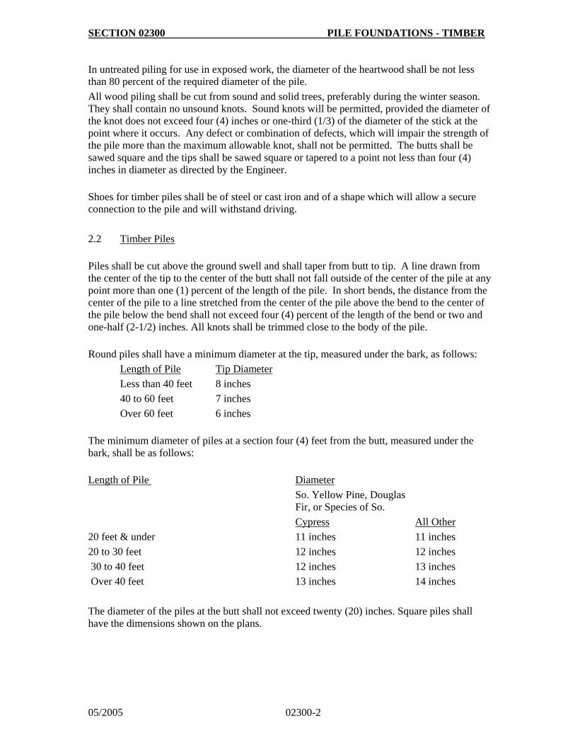
SECTION 02300 PILE FOUNDATIONS - TIMBER
05/2005 02300-2
In untreated piling for use in exposed work, the diameter of the heartwood shall be not less than 80 percent of the required diameter of the pile.
All wood piling shall be cut from sound and solid trees, preferably during the winter season. They shall contain no unsound knots. Sound knots will be permitted, provided the diameter of the knot does not exceed four (4) inches or one-third (1/3) of the diameter of the stick at the point where it occurs. Any defect or combination of defects, which will impair the strength of the pile more than the maximum allowable knot, shall not be permitted. The butts shall be sawed square and the tips shall be sawed square or tapered to a point not less than four (4) inches in diameter as directed by the Engineer.
Shoes for timber piles shall be of steel or cast iron and of a shape which will allow a secure connection to the pile and will withstand driving.
2.2 Timber Piles
Piles shall be cut above the ground swell and shall taper from butt to tip. A line drawn from the center of the tip to the center of the butt shall not fall outside of the center of the pile at any point more than one (1) percent of the length of the pile. In short bends, the distance from the center of the pile to a line stretched from the center of the pile above the bend to the center of the pile below the bend shall not exceed four (4) percent of the length of the bend or two and one-half (2-1/2) inches. All knots shall be trimmed close to the body of the pile.
Round piles shall have a minimum diameter at the tip, measured under the bark, as follows:
Length of Pile Tip Diameter
Less than 40 feet 8 inches
40 to 60 feet 7 inches
Over 60 feet 6 inches
The minimum diameter of piles at a section four (4) feet from the butt, measured under the bark, shall be as follows:
Length of Pile Diameter
So. Yellow Pine, Douglas Fir, or Species of So.
Cypress All Other
20 feet & under
20 to 30 feet
30 to 40 feet
Over 40 feet
11 inches
12 inches
12 inches
13 inches
11 inches
12 inches
13 inches
14 inches
The diameter of the piles at the butt shall not exceed twenty (20) inches. Square piles shall have the dimensions shown on the plans.
SECTION 02300 PILE FOUNDATIONS - TIMBER
05/2005 02300-3
PART 3 - EXECUTION
3.1 Inspection
Timber piles shall be branded, prior to shipment, with the supplier's brand, year of treatment, species of timber and preservative treatment, retentions and class and length. The brand symbols shall conform to the American Wood Preserver's Association Standard M6.
3.2 Installation
Unless otherwise specified, all piles shall be peeled by removing all of the rough bark and at least eighty (80) percent of the inner bark. No strip of inner bark remaining on the stick shall be over three-fourths (3/4) inch wide or over eight (8) inches long, and there shall be at least one (1) inch of clean wood surface between any two (2) such strips. Not less than eighty (80) percent of the surface on any circumference shall be clean wood.
The timber pile foundations shall be installed properly in the sizes and to the alignment, batter and bearing as shown on the approved plans.
Driving heads, mandrels or other devices shall be provided so that the piling will be driven without injury.
The piling heads shall be square and a driving cap provided to hold the axis of the pile in line with the axis of the hammer.
PART 4 - MEASUREMENT AND PAYMENT
Timber bearing piles will be measured by the number of linear feet from points of tips to heads of the piles remaining in place on the completed project. Payment shall be at the unit price stated in the Bid Proposal and shall include splicing, pointing tips; the furnishing, fitting and attaching of metal shoes or points painting, and for furnishing all other labor, tools, equipment and incidentals necessary to complete the work.

SECTION 02350 COFFERDAMS
05/2005 02350-1
PART 1 - GENERAL
1.1 Description of Work
Provide all labor, material, equipment and incidentals to furnish and place the cofferdams as called for on the approved plans and specified herein.
The work includes using cofferdams to allow the construction of substructures in open excavation.
1.2 Related Work Specified Elsewhere
Section 02100 - Clearing and Grubbing
Section 02200 - Earthwork for Structures and Pipelines
Section 02300 - Pile Foundations - Timbers
Section 02400 - Sheeting, Shoring and Bracing
Section 03100 - Concrete Formwork, Reinforcement and Materials
1.3 Permits and Regulations
The Contractor shall obtain all permits required by the State Water Control Board, and the United States Army Corps of Engineers.
1.4 Applicable References
A. Erosion and Sediment Control Ordinance (Chapter 57 of the Arlington County
Code)
B. Virginia Department of Transportation, Road and Bridge Specifications
(VDOT)
1.5 Submittals
The Contractor shall submit, upon request, drawings showing his proposed method of cofferdam construction and other details left to his option or not fully shown on the plans.
PART 2 - MATERIALS
Materials shall be at the Contractor's option with the approval of the Engineer.
PART 3 - EXECUTION
Cofferdams for foundation construction shall be as watertight as practicable and carried to a depth which will allow them to function properly without displacement. In general, the interior dimensions of cofferdams and cribs shall be such as to give sufficient clearance for the
SECTION 02350 COFFERDAMS
05/2005 02350-2
construction of forms, the inspection of their exteriors, and to permit pumping from outside of the forms. Cofferdams which are tilted or moved laterally during the process of sinking shall be corrected so as to provide the necessary clearance.
When conditions are encountered which render it impracticable to dewater the foundation, the Contractor may be required to construct a concrete foundation seal of such dimensions as may be necessary and the balance of the masonry shall be placed in the dry. When a foundation seal is placed under water, the cofferdam, if it is to remain in place, shall be vented or ported at low water level.
Cofferdams shall be constructed so as to protect fresh concrete against damage from a sudden rising of the stream and to prevent damage to the foundation by erosion. Timber or bracing shall not be left in cofferdams in such a way as to extend into the substructure masonry, unless specifically authorized by the Engineer.
Excavation shall not be made outside of cofferdams, except as necessary to permit the constructing of same. The natural stream bed adjacent to the structure shall not be disturbed without permission of the Engineer. If any excavation or dredging is made before the cofferdams are sunk or in place, the contractor shall, without extra compensation after the foundation base is in place, backfill all such excavation to the original ground surface or stream bed with approved material. Material deposited within the stream area from foundation or other excavation or from the filling of cofferdams shall be removed and the stream area freed from all obstructions caused by the Contractor's operations. The Contractor shall exercise every reasonable precaution throughout the duration of the project to prevent erosion of the soil and the pollution and siltation of rivers, streams and impoundments.
The Contractor shall prepare and submit a plan indicating the precautions to be followed to prevent the aforementioned conditions. Such plan shall be approved prior to beginning work. The plan shall include, but is not limited to, the specific location of all temporary structures or other obstructions which will constrict the stream flow; a description of construction activities which will contribute to the construction of the existing stream flow; the dimensions and number of all temporary structures and constructions that are to be placed in the stream at any one time; and a dimensional elevation view of the stream and proposed temporary structures and constrictions.
The Contractor shall prevent stream constriction which would reduce stream flows below the minimum, as defined by the State Water Control Board, during construction operations.
Unless otherwise provided, cofferdams or cribs with all sheeting and bracing shall be removed after the completion of the substructure, care being taken not to disturb or otherwise injure the finished masonry.
PART 4 - MEASUREMENT AND PAYMENT
Cofferdams shall be measured in vertical linear feet. Payment shall be at the contract unit price stated on the Bid Proposal and shall include all materials, labor and equipment for clearing and grubbing, excavation, placement, removal and backfill.
SHEETING, SECTION 02400 SHORING AND BRACING
05/2005 02400-1
PART 1 - GENERAL
1.1 Description of Work
Provide all labor, material, equipment, and incidentals to furnish and place the sheeting, shoring or bracing for the protection of the work and for the safety of personnel as called for on the approved plans and specified herein.
1.2 Related Work Specified Elsewhere
Section 02100 - Clearing and Grubbing
Section 02200 - Earthwork for Structures and Pipelines
Section 02300 - Pile Foundations - Timber
Section 02350 - Cofferdams
Section 03100 - Concrete Formwork, Reinforcement and Materials
1.3 Applicable Specifications
A. American Association of State Highways and Transportation Officials
(AASHTO)
B. American Society for Testing and Materials (ASTM)
C. Occupational Safety and Health Act (OSHA)
1.4 Applicable References
A. Erosion and Sediment Control Ordinance (Chapter 57 of the Arlington County
Code)
B. Virginia Department of Transportation, Road and Bridge Specifications (VDOT)
PART 2 - MATERIALS
Materials shall be of metal, wood or other material acceptable to the Engineer. Sheet steel piling shall conform to ASTM A-328. Structural timber and timber piles shall conform to AASHTO M-168.
PART 3 - EXECUTION
3.1 General
A. Be fully responsible for the design and supervision of installation and removal of all
sheeting, shoring and bracing required to support the excavation. Submit the design and proposed installation procedure to the Engineer for approval prior to any excavation. Approval by the Engineer will not relieve the Contractor of the responsibility for the adequacy of the shoring, and if at any time during the progress of
SHEETING, SECTION 02400 SHORING AND BRACING
05/2005 02400-2
the work it is determined by the Engineer that such design and installation is inadequate, the Contractor shall at his expense, furnish, install or make such changes in the plan or installation as may be necessary to perform the work in a manner satisfactory to the Engineer and in conformance with OSHA construction standards contained in the Department of Labor, OSHA Safety and Health Regulations for Construction.
B. The sheeting, shoring or bracing installation shall provide for the depth and width of
the excavation and the characteristics and water content of the soil. Also, weather conditions, the proximity of other structures, the vibration from construction equipment and/or vehicular traffic and spoil placement or other surcharge loads shall all be taken into account.
3.2 Installation
A. Furnish, put in place, and maintain such sheeting, bracing and shoring required to
support the sides of the excavation and to prevent any movement of earth which could in any way injure persons, endanger adjacent structures and utilities, or delay the work.
B. Whenever possible, drive sheeting ahead of the excavation to avoid loss of material
from behind the sheeting. If it is necessary to excavate below the sheeting, care shall be taken to avoid trimming behind the face along which the sheeting will be driven. Prevent voids outside of the sheeting. If voids are formed, fill immediately with sand and compact.
C. In areas not shown on the approved plans, where it is required to leave sheeting,
shoring and bracing in place to prevent injury to proximate structures, utilities and property, or the installation, the approval of the Engineer, in writing, shall be required for payment. Cut off sheeting and bracing at the elevations specified by the Engineer.
3.3 Removal
Remove sheeting, shoring and bracing during the backfill operations. Provide additional backfill compaction around the area of the pipe or structure to fill voids left behind the sheeting and shoring as it is removed. Avoid the production of loads which will increase the safe backfill load on the pipe or structure.
PART 4 - MEASUREMENT AND PAYMENT
4.1 Sheeting, Shoring and Bracing
A. Timber sheet piling, shoring and bracing, left in place as shown on the approved plans,
or approved by the Engineer, in writing, shall be measured in 1,000-feet-board measure (MFBM) for the materials actually left in place. Payment shall be at the unit price stated in the Bid Proposal and shall include all materials, labor, tools, equipment and incidental work necessary for the installation.
B. Steel sheet piling, left in place as shown on the approved plans or approved by the
Engineer, in writing, shall be measured in square feet (SF) for the materials actually left in place. Payment shall be at the unit price stated in the Bid Proposal and shall
SHEETING, SECTION 02400 SHORING AND BRACING
05/2005 02400-3
include all materials, labor, tools, equipment and incidental work necessary for the installation.
C. Sheeting, shoring and bracing removed from the installation shall be considered a
subsidiary obligation of the work to which it pertains. Payment for such sheeting, shoring and bracing shall be included in the unit and lump sum prices of the work to which it pertains.

SECTION 02500 STORM SEWERS AND DRAIN SYSTEMS
05/2005 02500-1 Rev 01/2008
PART 1 - GENERAL 1.1 Description of Work Provide all plant, labor, supervision, materials and equipment to furnish and lay all storm sewer pipe and appurtenances to the lines and depths called for on the approved plans. 1.2 Related Work Specified Elsewhere Section 02200 - Earthwork for Structures and Pipelines Section 02510 - Sanitary Sewers & Appurtenances Section 02950 - Tunneling Section 02951 - Boring and Jacking Section 03400 - Precast Concrete Section 04200 - Masonry Units Section 05500 - Structural Steel and Miscellaneous Metal 1.3 Applicable Specifications A. American Society for Testing and Materials (ASTM) B. Virginia Department of Transportation, Road and Bridge Specifications (VDOT) 1.4 Applicable Reference Erosion and Sediment Control Ordinance (Chapter 57 of the Arlington County Code) 1.5 Submittals Submit full descriptions and details of all pipe and appurtenances proposed for the project. Submit certifications from the manufacturers that the inspections and test specified in the referenced standards have been made and that the results of such inspections and tests comply with the requirements of the applicable standard. Certificates of compliance and approval shall apply. 1.6 Quality Assurance 1. The manufacturer shall provide facilities or a certified laboratory for conducting
load bearing, hydrostatic and other tests required for production by the ASTM. 2. The Engineer will inspect pipe, fittings and joint material upon delivery to the site.
The Contractor shall provide ample space between rows of stockpiled pipe to facilitate the inspection.
3. Final inspection will be conducted by the Engineer upon completion of final paving
and finished grading. PART 2 - MATERIALS 2.1 Storm Sewer Pipe All storm sewer pipes shall be reinforced concrete pipe with a minimum inside diameter of 15-inches. Reinforced concrete pipe shall be Class III, IV, or V as called for on the plans and shall conform to the specifications of ASTM C-76. The pipe shall have bell and spigot ends with rubber gasket joints conforming to ASTM C-443. Alternate materials may be approved by the Department of Environmental Services (DES) on a case by case basis.
SECTION 02500 STORM SEWERS AND DRAIN SYSTEMS
05/2005 02500-2 Rev 01/2008
2.2 Precast Concrete Manholes Precast concrete manhole bases, risers and cones shall conform to the requirements of Section 02510, 2.7 - Precast Concrete Manholes. 2.3 Brick Brick used in manhole bench and collar construction shall conform to the requirements of Section 04200 - Masonry Units. 2.4 Precast Concrete Blocks Precast concrete blocks shall not be used in construction of new storm drainage structures. Precast concrete blocks as approved by DES for the repair of existing concrete block structure shall conform to ASTM C-139. Blocks shall be not less than 5 inches by 8 inches and of proper radius and shape for sealing with mortar. 2.5 Mortar Mortar used in manhole construction shall be one part of Portland cement conforming to ASTM C-150, Type II, and two parts of sand conforming to ASTM C-144, with enough water added to produce mortar of the proper consistency for the type of joint. 2.6 Manhole Frames and Covers Manhole frames and covers shall be constructed of gray or ductile iron conforming to ASTM A-48 and A-536. Frames and covers shall have machined bearing surfaces to prevent rocking and rattling under traffic. Manhole covers shall be as shown on the Construction Standards and as indicated on the Contract Drawings. Frames and covers shall be manufactured by Dewey Brothers Inc., or equal. 2.7 Manhole Steps Manhole steps shall be as specified in Section 02510. 2.8 Manhole Neck Adjustments
Adjustments to manhole necks shall be limited to 2 inches of concrete. Concrete adjustment rings shall be used for adjustments in excess of 2 inches, but not to exceed 12 inches. Non-shrink grout shall be used between adjustment rings. 2.9 Quick-Setting Grout Quick-setting non-shrink grout shall conform to the requirements of VDOT, Octocrete, Speedcrete, or equal. 2.10 Miscellaneous Metals Structural steel, grating and miscellaneous metal shall conform to the requirements of Section 05500 - Structural Steel and Miscellaneous Metal. 2.11 Private Storm Sewer Connections
1. Storm Sewer Connections are privately owned and maintained from the storm sewer main up to and including the property served. Pipe and fitting for storm sewer service connections shall conform to the requirements of the Arlington County
SECTION 02500 STORM SEWERS AND DRAIN SYSTEMS
05/2005 02500-3 Rev 01/2008
Plumbing Code and Plumbing Code adopted by the State of Virginia.
2. No mechanical discharge of groundwater, stormwater, or other collected water onto
the public right of way shall be permitted.
3. Connections to existing storm sewer mains shall be at manholes or inlets. The connection shall be made by core-drilling the structure and using a manhole adaptor appropriate for the pipe and structure materials. Connections at brick or masonry structures shall be made by carefully chiseling or removing single bricks or blocks such that the clearance between the connection pipe and any portion of the manhole is minimized.
4. Connections directly to pipes shall not be allowed without specific approval by the DES Engineering Bureau and issuance of appropriate permits. Where specifically permitted by DES, connections to existing pipes shall be made using saddles or fittings designed specifically for use on the pipe material which it is proposed to be used upon. Concrete saddles shall not be permitted. For connections to pipes 24” and smaller, the saddle shall be a strap-style saddle, with straps extending around the entire circumference of the pipe. Connections to pipes larger than 24” shall use saddles or fittings specifically designed and manufactured for such connection, with appropriate anchors. When anchors are set into concrete pipes, expansion anchors shall not be permitted. Such fittings or saddles shall eliminate any encroachment of the pump discharge pipe into the flow line of the existing pipe when flowing full. Saddles shall provide flexural relief for the pump discharge line without transmitting any stress onto the storm sewer pipe.
PART 3 - EXECUTION 3.1 General A. Maintain a minimum 5-feet horizontal distance between storm sewer and all other
utilities. B. Temporarily support, protect and maintain all underground and surface structures and
utilities encountered in the process of the work. Where the grade or alignment of the pipe is obstructed by existing utilities, such as conduits, pipes or drains, the obstruction shall be permanently relocated by the Contractor in cooperation with the Owners of said utilities.
C. Use the proper tools for the safe handling and laying of pipe. Unload pipe by hand,
skidways or hoists in such a manner so that material is not dropped or damaged. Distribute pipe at site of installation near area where it is to be laid. Protect machined ends of pipe from damage and keep pipe free from dirt and debris.
D. Install piping in such a manner as to obtain sufficient flexibility and to prevent excessive
stresses in materials and excessive bending moments at joints. Conduct work in strict conformance with the procedures established by the manufacturers of the various types of pipe.
E. Bring any conflicts during the installation of piping to the attention of the Engineer. F. All storm drainage facilities to be accepted by the County for perpetual maintenance
shall be located such that maintenance and replacement can be accomplished without disturbing private-owned, permanent structures.
SECTION 02500 STORM SEWERS AND DRAIN SYSTEMS
05/2005 02500-4 Rev 01/2008
G. The minimum vertical clearance between storm sewer and other utilities shall be 1.0 foot, unless provisions to prevent damage to the underlying utility are detailed for approval by DPW.
H. Storm sewers shall be installed within public rights-of-way whenever possible.
Proposed storm sewers shall be installed such that the following horizontal clearance from any private property lines or buildings are maintained. When a storm sewer can not be installed with the minimum necessary horizontal clearance from private property, a permanent easement across the private property necessary to provide the horizontal clearances listed below shall be recorded prior to construction.
1. 10 feet from center line of storm sewer mains less than 27 inches in diameter and 10
feet or less in depth. 2. 15 feet from center line of storm sewer mains less than 27 inches in diameter and
greater than 10 feet in depth. 3. 15 feet plus half the diameter from the centerline of storm sewer mains greater than
27 inches, any depth. 4. The above standards and specifications may be modified in instances where
proposed development, site restrictions, and other unusual circumstances present unusual hardships and provisions are made to provide permanent sheeting shoring protection for the pipe.
I. Proposed easements shall be shown on plats prepared in conformance with plat
standards prescribed in chapter 23, subdivisions, of the Arlington County Code, and shall be submitted to the County for review and approval by the County Manager or designee. Deeds of easement shall be submitted to the County for review and approval, subject to the approval of the County Manager or designee, and approval as to form by the County Attorney.
J. No permanent structures, temporary structures, facilities or objects shall be placed
within a storm sewer easement without the approval of the County.
K. No new permanent structure may be constructed adjacent to an existing storm drainage facility where that new permanent structure interferes with or encumbers the maintenance or rehabilitation of the existing storm drainage facility.
L. Design plans shall show and clearly label the location of all existing and proposed storm
drainage easements. M. Where required, design plans shall show cross sections to demonstrate that proposed
facilities adjacent to County-owned storm drainage facilities will not impact the maintenance and reconstruction of the facility.
N. When abandoning existing storm sewers; excavate and remove existing structure and
storm sewer lines or abandon in place by filling pipes with flowable fill and plugging at all open ends. Excavate and remove structure to a minimum of 2 feet below finished grade, fill the structure with sand or #57 VDOT aggregate material.
O. All plans and specifications for construction of proposed storm sewer facilities must be
approved by DES. No sanitary sewer facilities shall be constructed without approved plans, shop drawings and construction cut sheets.
3.2 Laying Pipe A. Lay pipe to a true uniform line and grade from elevations indicated on the drawings with
continuous bearing of barrel on cradle or bedding material.
SECTION 02500 STORM SEWERS AND DRAIN SYSTEMS
05/2005 02500-5 Rev 01/2008
B. Lay pipe up-grade with the bell end pointing in the upstream direction and the spigot end pointing in the downstream direction. Lay each section of pipe in such a manner as to form a close concentric joint with the adjoining section and to prevent any sudden offsets in the flow line.
C. Ensure that pipe is well bedded on a solid foundation. Correct any defects due to
settlement. Excavate bell holes sufficiently large to ensure making of proper joints. Exercise precautions to include the furnishing and placing of bedding to prevent any pipe from resting directly on rock.
D. Plug or grout lift holes left in the pipe prior to backfilling operations. E. As the work progresses, clear the interior of the pipe of all dirt and superfluous materials
of every description. F. Keep trenches and excavations free of water during construction and until final
inspection. Do not lay pipe in water or in a frozen bedding condition. Prevent flotation and re-lay pipe that has floated.
3.3 Manhole and Catch Basin Construction A. Construct manholes of precast concrete in accordance with Standard Details and the
plans, unless directed otherwise. Provide monolithic base of precast construction and make water-tight connections between base and risers, unless modifications to the existing system are being performed. Manhole wall and bottom construction shall be such as to ensure water tightness. If directed by DES, the entire wall exterior shall be painted with waterproof coating. Place axis of manholes directly over the center lines of the pipes unless otherwise shown. The manhole foundation shall be adequately designed to support the manhole and any superimposed loads that may occur. Manholes in fill areas shall have a foundation extending a minimum depth of 18 inches into undisturbed earth and shall be designed only with prior approval of DES.
B. Construct appropriate flow channels in the bottom of manholes and catch basins as
shown on the Construction Standards and plans. Cast-in-place concrete shall be a minimum four-inches thick, non-reinforced, 3000 psi concrete with smooth form troweled finish. Flow channel construction shall provide a smooth transition between adjacent sections. Provide a positive means of bonding channel to base of structure.
C. Cast-in-place concrete for manholes and catch basins shall be placed monolithically.
Concrete shall be allowed to drop freely up to five-feet in height; where greater drops are required, a tremie or other device approved by the Engineer shall be used.
D. Joints for brickwork and precast concrete block work shall be completely filled and shall
be smooth and free from surplus mortar on the inside of the manhole. Brick shall be laid radially with every sixth course laid as a stretcher courses. Brick and concrete block manholes and catch basins shall be parged over the entire inside surface of the walls.
E. Cut all pipes flush with the inside wall of the manhole structure. In 48-inch diameter
precast structures, provide flexible rubber gasket between the structure wall and the incoming pipe. Provide field sleeve where required to assure a tight fit. In structures larger than 48-inches, secure pipe tightly into the wall with quick-setting non-shrink grout.
F. Firmly anchor manhole steps to wall according to manufacturer's recommendations.
Steps shall be installed in accordance with Standard Drawing M-2.0.
G. Install vented or bolted manhole frames and covers, as indicated on the plans. Adjust the frame and cover to finished grade by brick or concrete adjusting ring construction.
SECTION 02500 STORM SEWERS AND DRAIN SYSTEMS
05/2005 02500-6 Rev 01/2008
H. For repair of existing structures, joints for brickwork and precast concrete block work shall be completely filled and shall be smooth and free from surplus mortar on the inside of the structure. Brick shall be laid radially with every sixth course laid as a stretcher course. Brick and concrete block manholes shall be plastered with mortar over the entire outside surface of the walls.
3.4 Minimum Requirements for As-Built Plan
A Upon completion of the construction and prior to release of bonds or final payments by
the County the Contractor shall submit and obtain approval of as-built plans. One set of as-built plans shall be provided on mylar and one copy in electronic format and shall include:
1. Invert elevations
2. Manhole top elevations
3. Percent of grade between structures
4. Horizontal distance between structures and manholes
5. Pipe material
6. Location of connection to existing system
7. Type of structures installed
8. Label on plan and profile the point of private and public responsibility for
maintenance PART 4 - MEASUREMENT AND PAYMENT 4.1 Storm Sewer Storm sewer for the various classes and sizes shown on the bid proposal shall be measured in linear feet along the center line of the pipe and shall be measured from inside wall of manhole or catch basin to inside wall of manhole or catch basin. Payment shall include the furnishing of all pipe and fittings, all necessary tests, excavation, removal and disposal of existing pipes, fittings and unsuitable or surplus material, placement of backfill and bedding as shown in the "Trench in Earth" Standard M-3.0, erosion and sediment control, and all work incidental to providing a complete storm sewer installation, regardless of the depth of the pipe. 4.2 Manholes Manholes shall be measured by the vertical foot from the invert of the outlet pipe to the top of the manhole cover. Payment shall include precast manholes, concrete base and channels, frame and cover, steps, excavation, backfill, bedding, and all other work necessary for a complete installation.
4.3 Catch Basins, Yard Inlets and Catch Basins Converted to Manholes Catch basins, yard inlets and catch basins converted to manholes shall be measured as each. Payment shall include concrete base and channels, frame and cover, steps, excavation, backfill, bedding, and all other work necessary for a complete installation.

SECTION 02500 STORM SEWERS AND DRAIN SYSTEMS
05/2005 02500-7 Rev 01/2008
4.4 Excavation Below Grade and Additional Bedding Over excavation, additional bedding and other work related to earthwork shall be measured in accordance with Section 02200.

SECTION 02510 SANITARY SEWERS AND APPURTENANCES
05/2005 02510-1 Rev 01/2008
PART 1 - GENERAL
1.1 Description of Work
Provide all plant, labor, supervision, materials and equipment to furnish and lay all sanitary sewer pipe and appurtenances to the lines and depths called for on the approved plans.
1.2 Related Work Specified Elsewhere
Section 02200 - Earthwork for Structures and Pipelines
Section 02950 - Tunneling
Section 02951 - Boring and Jacking
Section 03400 - Precast Concrete
1.3 Applicable Specifications
A. American Association of State Highway and Transportation Officials
(AASHTO).
B. American National Standards Institute (ANSI).
C. Arlington County Plumbing Code (Chapter 18 of the Arlington County Code).
D. Arlington County Utilities Code (Chapter 26 of the Arlington County Code).
E. Plumbing Code adopted by the State of Virginia.
F. American Society for Testing and Materials (ASTM).
G. American Water Works Association (AWWA).
H. Corps of Engineers CRD-588.
1.4 Applicable Reference
A. Erosion and Sediment Control Ordinance (Chapter 57 of the Arlington County
Code).
B. Virginia Department of Health (VDH) and State Water Control Board
Sewerage Regulations (VR 355-17-000) [Section 62.1-44.19(8) of the Virginia Code].
1.5 Submittals
Submit full descriptions and details of all pipe, precast manholes, frames and covers, and other appurtenances proposed for the project.
Submit certifications from the manufacturers that the inspections and tests specified in the referenced standards have been made and that the results of such inspections and tests comply with the requirements of the applicable standard.
1.6 Quality Assurance
A. Inspection and Testing of Pipe

SECTION 02510 SANITARY SEWERS AND APPURTENANCES
05/2005 02510-2 Rev 01/2008
1. The Engineer will inspect pipe, fittings and joint material upon delivery to the site. The Contractor shall provide ample space between rows of stockpiled pipe to facilitate the inspection.
2. The manufacturer shall provide facilities or a certified laboratory for
conducting load bearing, hydrostatic and other tests required for production by the ASTM.
3. Air tests and infiltration tests of the completed installation shall be
conducted by the Contractor in the presence of the Engineer.
4. Final inspection will be conducted by the Engineer after completion of final paving and finished grading.
B. Sanitary Sewer Field Tests
Conduct field tests as specified in paragraph 3.6.
C. Force Main Field Tests
Hydrostatic testing of force mains shall conform to the hydrostatic testing
specifications of Section 02550, except that the entire force main may be pressure tested at one time.
PART 2 - MATERIALS
2.1 Concrete Pipe
Concrete pipe smaller than 12-inch shall not be used as sanitary sewer pipe. Concrete sewer pipe 12-inch and larger may be used only with special approval and shall be reinforced concrete pipe (RCP), of minimum Class IV, conforming to ASTM C-76. The pipe shall have bell and spigot ends with rubber gasket joints conforming to ASTM C-443.
2.2 Vitrified Clay Pipe
Vitrified clay pipe shall not be used as sanitary sewer pipe.
2.3 Asbestos-Cement Pipe
Asbestos-cement pipe shall not be used as sanitary sewer pipe.
2.4 Ductile Iron Pipe (DIP)
Ductile iron pipe shall conform to AWWA C-151 (ANSI A21.51), minimum class 52. Pipe lining shall be corrosion resistant to sewer gas, sewpercoat, protecto 401 or approved equal
SECTION 02510 SANITARY SEWERS AND APPURTENANCES
05/2005 02510-3 Rev 01/2008
and shall have mechanical or push-on joints utilizing rubber gasket rings conforming to AWWA C-111 (ANSI A21.11). Fittings shall be ductile-iron, mechanical joint conforming to AWWA C-110 (ANSI A21.10) with double cement lining. Force mains shall be minimum class 52 ductile iron pipe.
2.5 Polyvinyl Chloride pipe (PVC)
PVC pipe and fittings, 4-inch through 15-inch maximum diameter, shall meet requirements of ASTM D3034, wall thickness classification SDR-35 and shall be colored green for in-ground 02510-3 identification as sewer pipe.
PVC pipe shall be furnished in lengths of not less than 12 feet. PVC pipe and fittings shall be legibly marked in accordance with ASTM D3034, and in addition shall have the following markings; manufacturer's lot number, date of manufacture and point of origin. Pipe not marked as indicated will be rejected. Date of manufacture shall not be more than six (6) months prior to date of installation. Pipe and fittings shall have integral bell gasket joint. Joints shall meet the requirements of ASTM D-3212, and gasket shall meet requirements of ASTM F477.
2.6 Sewer Service Connections
Sanitary Sewer Connections are privately owned and maintained from the sewer main up to and including the building served. Pipe and fitting for sewer service connections shall conform to the requirements of the Arlington County Plumbing Code and Plumbing Code adopted by the State of Virginia.
Where the flood level rims of plumbing fixtures are below the elevation of the manhole cover of the next upstream manhole in the public sewer, such fixtures may require the installation of a backwater valve. Design of backwater valves and these fixtures shall be completed per the applicable provisions of the Plumbing Code adopted by the State of Virginia and Arlington County Plumbing Code.
Taps to existing sanitary sewer mains shall use approved tapping saddles. Where the existing pipe is HDPE eltrofusion saddles shall be used. Only approved manufactured tee or wye fittings shall be used for any lateral connections to new sanitary sewer mains. No taps shall be allowed in the installation of new sanitary sewer mains.
2.7 Precast Concrete Manholes
Precast concrete manhole bases, risers and cones shall conform to the requirements of ASTM C-478 with configurations as shown in the drawings. Cones shall be eccentric. Manhole sections for sanitary sewers shall be of male and female end type with a preformed groove provided in the male end for placement of a round rubber gasket ring. Rubber gasket rings shall meet the requirements of ASTM C-361 or C-443. The gasket shall be the sole element utilized in sealing the joint from either external or internal hydrostatic pressure. Use the appropriate lubricant as directed by the manufacturer.
SECTION 02510 SANITARY SEWERS AND APPURTENANCES
05/2005 02510-4 Rev 01/2008
Each precast section shall be clearly marked on the inside near the top with the following information where applicable: ASTM designation, Standard detail or drawing number, station location and designation, date of manufacture and name or trademark of manufacturer. Precast concrete manholes shall be manufactured by Americast, or approved equal.
2.8 Manhole Neck Adjustments
Adjustments to manhole necks shall be limited to 2 inches of concrete. Concrete adjustment rings shall be used for adjustments in excess of 2 inches, but not to exceed 12 inches. Non-shrink grout shall be used between adjustment rings.
2.9 Precast Concrete Blocks
Precast concrete blocks, as approved for use by the Arlington County Department of Environmental Services (DES), shall conform to ASTM C-139. Blocks shall not be less than 5-inches by 8-inches and of proper radius and shape for sealing with mortar.
2.10 Mortar
Mortar used in the repair of existing concrete block structures shall be one part Portland cement conforming to ASTM C-150, Type II, and two parts sand conforming to ASTM C144, with enough water added to produce mortar of the proper consistency for the type of joint.
2.11 Manhole Frames and Covers
Manhole frames and covers shall be constructed of gray or ductile iron conforming to ASTM A-48 and A-536. Frames and covers shall have machined bearing surfaces to prevent rocking and rattling under traffic. Manhole covers shall be as shown on the standard details and as indicated on the approved plans. Frames and covers shall be manufactured by Capitol Foundry, or approved equal.
2.12 Flexible Plastic Gasket
Flexible plastic gaskets between bolted manhole cover and manhole frame seat shall be extruded rope Type B, conforming to AASHTO M-198, butyl based, 3/4 inch diameter minimum.
2.13 Manhole Steps
Manhole steps shall be a composite of a No. 3 grade 60 deformed steel bar encased in copolymer polypropylene plastic of the “press-fit” design or rubber. Steps shall be PSI-PF as manufactured by M. A. Industries, Inc., or Wedge-Lok as manufactured by Delta Pipe Products, Inc., or equal.
2.14 Manhole Pipe Sleeves or Boots
SECTION 02510 SANITARY SEWERS AND APPURTENANCES
05/2005 02510-5 Rev 01/2008
All sanitary sewer main connections to existing manholes shall be made by coring the manhole wall above the existing bench. Sewer pipe shall be connected to manhole by approved flexible boot.
Flexible connection of sewer pipe to manhole shall provide a positive, watertight compression joint allowing for 10o omni-directional deflection. Manhole boots or sleeves shall be manufactured of 3/8-inch flexible neoprene rubber conforming to ASTM C-443 specifications or 3/16-inch flexible ethylene propylene rubber conforming to ASTM C-923. Sleeves shall utilize a stainless steel clamp to secure pipe and shall be the flexible rubber foot of the “Kor 'N' Seal” system as manufactured by an approved manufacturer.
2.15 Waterproof Coating
Waterproof coating for exterior of manholes, if required by DES, shall be as specified in Section 07100 - Waterproofing.
2.16 Quick-Setting Grout
Quick-setting non-shrink grout shall conform to Corps of Engineers CRD-588, Octocrete, Speedcrete, or equal.
PART 3 - EXECUTION
3.1 Design Basis
A. Per Capita Flow
New sanitary sewer systems shall be designed on the basis of an average daily per capita flow as follows:
Establishment
Single Family
Multi-Family
Apartment
Hotel
Manufacturing
Transportation
Trade
Office
Restaurant
Service
Intensive Service
Other
School
Church
Average Daily Usage
225 gallons per day (gpd)/unit
205 gpd/unit
160 gpd/unit
80 gpd/room
0.03 gpd/sq. ft. GFA
0.11 gpd/sq. ft. GFA
0.05 gpd/sq. ft. GFA
0.40 gpd/sq. ft. GFA
0.09 gpd/sq. ft. GFA
0.50 gpd/sq. ft. GFA
0.07 gpd/sq. ft. GFA
0.03 gpd/sq. ft. GFA
1000 gpd/church
Note: GFA = Gross Floor Area
SECTION 02510 SANITARY SEWERS AND APPURTENANCES
05/2005 02510-6 Rev 01/2008
B. Lateral and Sub-main Sewers
1 “Lateral” means a sewer that has no other common sewers discharging into it.
2 “Sub-main” means a sewer that receives flow from one or more lateral sewers.
3 Lateral and sub-main sewers shall be designed to carry a peak flow when full as determined by applying a peak flow factor of 4.0 to the average daily flow.
C. Main, Trunk, and Interceptor Sewers
1 “Main or trunk” means a sewer that receives sewage flow from one or more sub-main sewers.
2 “Interceptor” means a sewer that receives sewage flow from a number of gravity mains, trunk sewers, sewage force mains, etc.
3 Main, trunk, and interceptor sewers shall be designed to carry a peak flow when full as determined by applying a peak flow factor of 3.0 to the average daily flow.
3.2 Sanitary Sewer Design Criteria
Sanitary sewers shall be designed and installed in accordance with Arlington County Standard Details and Specifications, the Virginia Department of Health and State Water Control Board Sewerage Regulations, Water Pollution Federation Standards, the Uniform Statewide Building Code of Virginia, and the following design criteria:
A. All data regarding size of building, type of occupancy, number of occupants and
estimated peak water demands as applicable for all buildings within the proposed development shall be furnished to DES to substantiate sanitary sewer main sizes. The final size of all sanitary sewer mains and appurtenances shall be determined by DES.
B. Sanitary sewer mains shall be a minimum 8-inches in diameter and shall be installed in
straight alignment and grade between manholes. Minimum sewer slopes should be 0.5%. Minimum slopes for terminal sewer segments and sewers serving less than 10 households or their equivalent should be 1.0%. Slopes less than those mentioned above shall only be considered for approval by DES in extreme cases with justification provided by the Engineer. Absolute minimum allowable slopes for various sized pipes shall conform to Virginia Department of Health Sewerage Regulation VR 355-17-106.05(c) for non-settled sewage. Maximum sewer slopes shall be 15%. Slopes shall be determined between centers of manholes.
C. Sanitary sewers shall be installed at depths sufficient to serve existing and proposed
basements. Minimum cover over sewers shall be 6 feet in streets and areas subject to vehicular traffic and shall be 4 feet in other areas.
D. Stream and estuary crossings shall have a 3 foot minimum cover if possible and sewer
pipe shall be ductile iron encased in concrete from manhole to manhole. The pipe and
SECTION 02510 SANITARY SEWERS AND APPURTENANCES
05/2005 02510-7 Rev 01/2008
joints shall be tested in place and shall exhibit zero infiltration. Sewers located adjacent to streams shall be located outside of the stream bed whenever possible and should be sufficiently removed there from to provide for possible future channel widening.
E. Gravity sewer size shall remain constant between manholes. Where a smaller sewer
enters a larger one, the relative elevations of the inverts of the sewers shall be arranged to maintain approximately the same energy gradient.
F. When pipe velocities greater than 15 feet per second are expected, special provisions
shall be made to protect against internal erosion due to high velocity. The pipe shall conform to applicable ASTM, AWWA, ANSI, or other appropriate standards or specifications which provide protection against internal erosion.
G. Sanitary sewers shall be installed within street right of way and shall follow the street
centerline wherever possible. The sewer shall extend a minimum of 10 feet along the property frontage of the last house being served. Sewers shall not be located longitudinally under walks. Sewers shall be installed within recorded easements on private property when locations in public right of way are not possible. Such easements, of the width detailed below, shall be recorded prior to final approval and issuance of building permits.
1. 10 feet from center line of sewer mains less than 15 inches in diameter and 10 feet or
less in depth.
2. 15 feet from center line of sewer mains greater than 15” in diameter or any size sanitary sewer main greater than 10’ in depth.
3. The above standards and specifications may be modified in instances where
proposed development, site restrictions, and other unusual circumstances present unusual hardships and provisions are made to provide permanent sheeting shoring protection for the pipe.
H. The minimum clear horizontal separation between sanitary sewer mains or sewer
manholes and water mains shall be 10 feet. When local conditions prevent a minimum separation of 10 feet, a closer separation may be allowed provided that:
1. Sanitary sewer manholes shall be of watertight construction and tested in place.
2. The top (crown) of the sanitary sewer main shall be a minimum of 18 inches
below the bottom (invert) of the water main. The sewer main and water main shall be kept in separated trenches. Where minimum vertical separation cannot be obtained, the sanitary sewer shall be constructed of ductile iron pipe and pressure tested in place without leakage prior to backfilling.
I. Sewer mains crossing under water mains shall be laid to provide a minimum vertical separation of 18 inches between the top of the sewer and bottom of the water main. If local conditions prevent this, the water main shall be relocated to provide the separation directed by the Engineer, or the sewer shall be constructed of ductile iron pipe, pressure tested in place without leakage before backfill, and with no joint of the sewer closer than 8 feet of the water main.
SECTION 02510 SANITARY SEWERS AND APPURTENANCES
05/2005 02510-8 Rev 01/2008
J. Sanitary sewer mains crossing over water mains shall maintain a minimum vertical
separation of 18 inches between the top of the water main and the bottom of the sewer. The sanitary sewer shall be constructed of ductile iron pipe, pressure tested in place without leakage before backfill. Provide adequate structural support for the sewer to prevent excessive joint deflection and the settling on and breakage of the water main (refer to Standard Drawing M-7.0).
K. The minimum clear horizontal separation between sanitary sewer and utilities other
than water main shall be 5 feet (see 3.2.H for separation between sanitary sewer and water main).
L. The minimum vertical clearance between sanitary sewer and utilities other than water
main shall be 1.0 foot, unless provisions to prevent damage to the underlying utility are detailed for approval by DES.
M. The minimum clear horizontal separation between sanitary sewer and buildings or
other structures shall be as follows:
1. 10 feet for sanitary sewer mains less than 15 inches in diameter and 10 feet or
less in depth.
2. 15 feet for sanitary sewer mains 15 inches and larger in diameter or any sanitary sewer in excess of 10 feet in depth.
N. Individual building or house sewer services 5 inches and smaller shall be connected to the sanitary sewer main in accordance with the Arlington County Plumbing Code. Sanitary sewer services 6 inches and larger and sewer services serving more than one building, townhouse or similar structure shall be connected to a manhole on the sanitary sewer main as directed by DES. Existing manholes receiving new sewer services must be approved by DES and shall be reconstructed or replaced as directed by DES to meet current Standards. No sanitary sewer service taps shall be made in trunk sewers 15 inches and larger without special approval from DES.
O. All plans and specifications for construction of proposed sanitary sewer facilities must
be approved by DES. No sanitary sewer facilities shall be constructed without approved plans, shop drawings and construction cut sheets.
3.3 Laying Pipe
A. Temporarily support, protect and maintain all underground and surface structures and
utilities encountered in the process of the work. Where the grade or alignment of the pipe is obstructed by existing utilities, such as conduits, pipes or drains, the obstruction shall be permanently relocated and supported by the Contractor in cooperation with the owners of said utilities.
B. Use the proper tools for the safe handling and laying of pipe. Unload pipe by hand,
skidways or hoists in such a manner so that material is not dropped or damaged.
SECTION 02510 SANITARY SEWERS AND APPURTENANCES
05/2005 02510-9 Rev 01/2008
Distribute pipe at site of installation near area where it is to be laid. Protect machined ends of pipe from damage and keep pipe free from dirt and debris.
C. Install piping in such a manner as to obtain sufficient flexibility and to prevent
excessive stresses in materials and excessive bending moments at joints. Conduct work in strict conformance with the procedures established by the manufacturers of the various types of pipe.
D. Use full lengths of pipe wherever possible. Do not use short lengths of pipe with
couplings without approval of the Engineer. Cut pipe to exact measurement and install without forcing or springing.
E. Bring any conflict, during the installation of piping, to the attention of the Engineer. Do
not improvise or make field changes without the approval of the Engineer.
F. Lay pipe to a true uniform line and grade from elevations indicated on the drawings
with continuous bearing of barrel on cradle or bedding material.
G. Lay pipe upgrade with the bell end pointing in the upstream direction and the spigot
end pointing in the downstream direction. Lay each section of pipe in such a manner as to form a close concentric joint with the adjoining section and to prevent any sudden offsets in the flow line.
H. Ensure that pipe is well bedded on a solid foundation. Only Class A, B, or C bedding
and AWWA class shall be permitted. Correct any defects due to settlement. Excavate bell holes sufficiently large, to ensure making of proper joints. Exercise precautions to include the furnishing and placing of bedding to prevent any pipe from resting directly on rock. Upon ensuring that the joint of pipe is on proper line and grade, the pipe must be held in place while stone is hand chocked under the haunches for the full length of the pipe. Verify grade and alignment before placing enough stone to adequately cover pipe and prevent movement. Check grade and alignment once again. Special attention should be given to the area of bedding between the end of the pipe trench and manhole connection. Refer to Section 02200 - Backfill for Pipelines for additional requirements and Standard Drawing S-4.0 for pipe and bedding details.
I. As the work progresses, clear the interior of the pipe of all dirt and superfluous
materials of every description. Utilize a suitable swab or drag in small diameter pipes and pull forward past each joint immediately after the joining has been completed.
J. Keep trenches and excavations free of water during construction and until final
inspection. Do not lay pipe in water or in a frozen bedding condition. Prevent flotation and re-lay pipe that has floated.
K. When work is not in progress, securely close open ends of pipe to prevent trench water,
earth or other substances from entering the pipe.
L. Prevent pipe lining and coating from being damaged. Carefully inspect all materials
for defects before lowering into trench.
SECTION 02510 SANITARY SEWERS AND APPURTENANCES
05/2005 02510-10 Rev 01/2008
M. Provide temporary service to customers in the area of construction, by providing by-pass pumping, unless specified otherwise on the approved plans.
N. When abandoning existing manholes and/or sewer lines, plug all pipes at all open ends. Excavate within the manhole to a point 2-feet below finished grade, fill the manhole with sand or #57 VDOT aggregate material and deliver the frame and cover to the Arlington County Department of Environmental Services, Water/Sewer/Streets Division.
O. Ventilation of gravity sewer systems shall be provided where continuous watertight sections (including manholes with watertight covers) greater than 1,000 feet in length are incurred [conforms to Virginia Department of Health Sewerage Regulation VR 355-17106.07(G)].
P. Sanitary sewer lines constructed in fill areas shall be continuous ductile iron (CL-50) run from manhole to manhole. Fill material beneath the pipe shall be select material compacted to 95 percent density at optimum moisture (ASTM Proctor Test). Refer to 3.4C for manholes in fill areas.
3.4 Manhole Construction
A. Construct manholes of precast concrete in accordance with Standard Details
and the plans, unless directed otherwise. Provide monolithic base of precast construction and make water-tight connections between base and risers, unless modifications to the existing system are being performed. Manhole wall and bottom construction shall be such as to ensure water tightness. If directed by DES, the entire wall exterior shall be painted with waterproof coating. Place axis of manholes directly over the center lines of the pipes unless otherwise shown. The manhole foundation shall be adequately designed to support the manhole and any superimposed loads that may occur.
B. Manholes shall be minimum 4 feet inside diameter with a minimum clear
opening in the manhole frame of 24 inches. Manholes shall be a maximum 16 feet deep and shall be installed at all changes in sewer size, material, alignment or grade and at terminal end of sewer. Manholes deeper than 16 feet shall only be considered for approval by DES in extreme cases with justification provided by the Engineer. Maximum spacing of manholes shall be 350 feet. Crown of inlet sewers shall not be lower than crown of outlet sewer.
C. Drop connections should be avoided and will be allowed only upon approval
by DES when normal connections are not practical. Drop connections shall provide a minimum drop in a manhole of two feet measured from the invert of the incoming pipe to the manhole invert (refer to Standard Drawing S-2.3). Inside drop connections shall only be allowed in 5 foot inside diameter manholes and shall only be used under special circumstances such as high water table, utility conflicts and excessive depths.
D. Construct appropriate flow channels in the bottom of manholes as shown on the Standard Details and plans. Cast-in-place concrete shall be a minimum 4
SECTION 02510 SANITARY SEWERS AND APPURTENANCES
05/2005 02510-11 Rev 01/2008
inches thick, non-reinforced, 3000 psi concrete with smooth form troweled finish. Flow channel construction shall provide a smooth transition between adjacent sewer sections to reduce turbulence. Benches shall be sloped to the channel to prevent accumulation of solids. Provide a positive means of bonding channel to manhole base.
E. The minimum invert drop from inlet to outlet of a manhole shall be 0.10 foot.
F. Manholes in fill areas shall have a foundation extending a minimum depth of 18
inches into undisturbed earth and shall be designed only with prior approval of DES.
G. Cast-in-place concrete for manholes shall be placed monolithically. Concrete
will be allowed to drop freely up to 5 feet in height. Where greater drops are required, a tremie or other device approved by the Engineer shall be used.
H. For repair of existing manholes, joints for brickwork and precast concrete block
work shall be completely filled and shall be smooth and free from surplus mortar on the inside of the manhole. Brick shall be laid radially with every sixth course laid as a stretcher course. Brick and concrete block manholes shall be plastered with mortar over the entire outside surface of the walls.
I. All manholes subject to infiltration of ponded surface water those with top
elevations lower than the 25-year flood elevations shall be provided with watertight manhole frame and bolted cover (refer to Standard Drawings S-3.1 and S-3.2).
J. Cut all pipes flush with the inside wall of the manhole structure. In all
diameter sewer manholes, provide flexible rubber gasket between manhole wall and the incoming pipe. Provide field sleeve where required to assure a tight fit.
K. Firmly anchor manhole steps to wall according to manufacturer's recommendations. Steps shall be installed in accordance with Standard Drawing M-2.0.
L. Install manhole frames and covers, as indicated on the plans. Adjust the frame
and cover to finished grade by concrete adjusting ring. Provide flexible plastic gasket between the cover of manholes to be bolted and the manhole frame. Cement the rubber gasket to the frame with a water-resistant material (such as 3M Super Weather Strip Adhesive, part 8001).
3.5 Sewer Service Connections
Sewer service connections to the sanitary sewer main shall be made only by a licensed plumber and in accordance with the Plumbing Code adopted by the State of Virginia and the Arlington County Plumbing Code. No sewer service connections shall be made within 2 feet of any joint in the sanitary main or within 5 feet along the pipe leading from a terminal manhole. The minimum allowable distance between sewer service connections at the sewer
SECTION 02510 SANITARY SEWERS AND APPURTENANCES
05/2005 02510-12 Rev 01/2008
main shall be 3 feet. No house service lateral shall be connected to an existing manhole without the special approval of DES.
3.6 Sanitary Sewer Acceptance Tests
A. General: Acceptance tests (air tests) shall be specified for all new sanitary sewer main
construction. Acceptance tests shall not be made until all sanitary sewer pipes, manholes and required building spurs have been installed, and the pipe trenches are backfilled to the finished grade and compacted. Prior to backfilling sanitary sewer sections, the Contractor may perform preliminary tests at his own discretion without the presence of the Engineer. The Contractor shall schedule the final acceptance tests with the Engineer at least 48 hours in advance. Final acceptance tests shall be performed in the presence of the Engineer or his duly authorized representative. All material, equipment and labor required shall be provided by the Contractor. Sewer pipes shall be tested from manhole to manhole or from manhole to terminus. Sections passing the acceptance tests shall continue to be maintained by the Contractor until a satisfactory final inspection of the entire sewer system is completed.
B. Low Pressure Air Tests: Sanitary sewer sections of one diameter only and above the
ground water table shall be tested using low air pressures after completion of backfill and before hookup of house connections. Temporarily cap all laterals and secure brace for the test. Inspect sewers and manholes prior to testing and remove all soil and debris by thoroughly flushing the lines. Dispose of soil and debris without using the existing sewer system. Provide and securely brace test plugs at each manhole. After all personnel are removed from manholes, add air slowly to the portion of the pipe being tested until internal air pressure is held at a test pressure of 4.0 pounds per square inch (psi) for a minimum of two minutes. Pressure gauges used in the air test procedure shall be calibrated in divisions of 0.10 psi.
If, in the Engineer's opinion, there is any indication of leakage at the test plug, relieve
the internal pressure before taking steps to eliminate the leak. After the two-minute holding period at 4.0 psi, disconnect hose and compressor from the pipe section being tested. If pressure decreases to 3.5 psi, observe and record the time required for the pressure to drop 1.0 psi from 3.5 to 2.5 psi. Pipes failing to maintain minimum acceptable holding times in accordance with ASTM-C828 (refer to Air Test Table herein) will not be accepted. Make repairs or replacement as required at no cost to the County and retest as specified above.
C. Mandrel Testing: All PVC sewer lines shall require Mandrel testing in addition to air
test acceptance to determine if they are within the allowable deflection tolerance. The Contractor shall perform the deflection test by utilizing an approved go/no go multi-arm mandrel which meets ASTM D-3034 dimensions for 7.5 percent deflection limit.
D. Manhole Testing: Manholes may be tested for leakage at the same time that gravity
sewer lines are being tested for leakage. Manhole inverts shall be completed before testing is performed.
Vacuum testing shall include vacuum pump, certified vacuum gauge with a range of 0
to 30 inch mercury (Hg.), sealing element with manhole support brace and air pressure to monitor the inflatable sealing ring. Evacuate the manhole to 10 inches Hg.
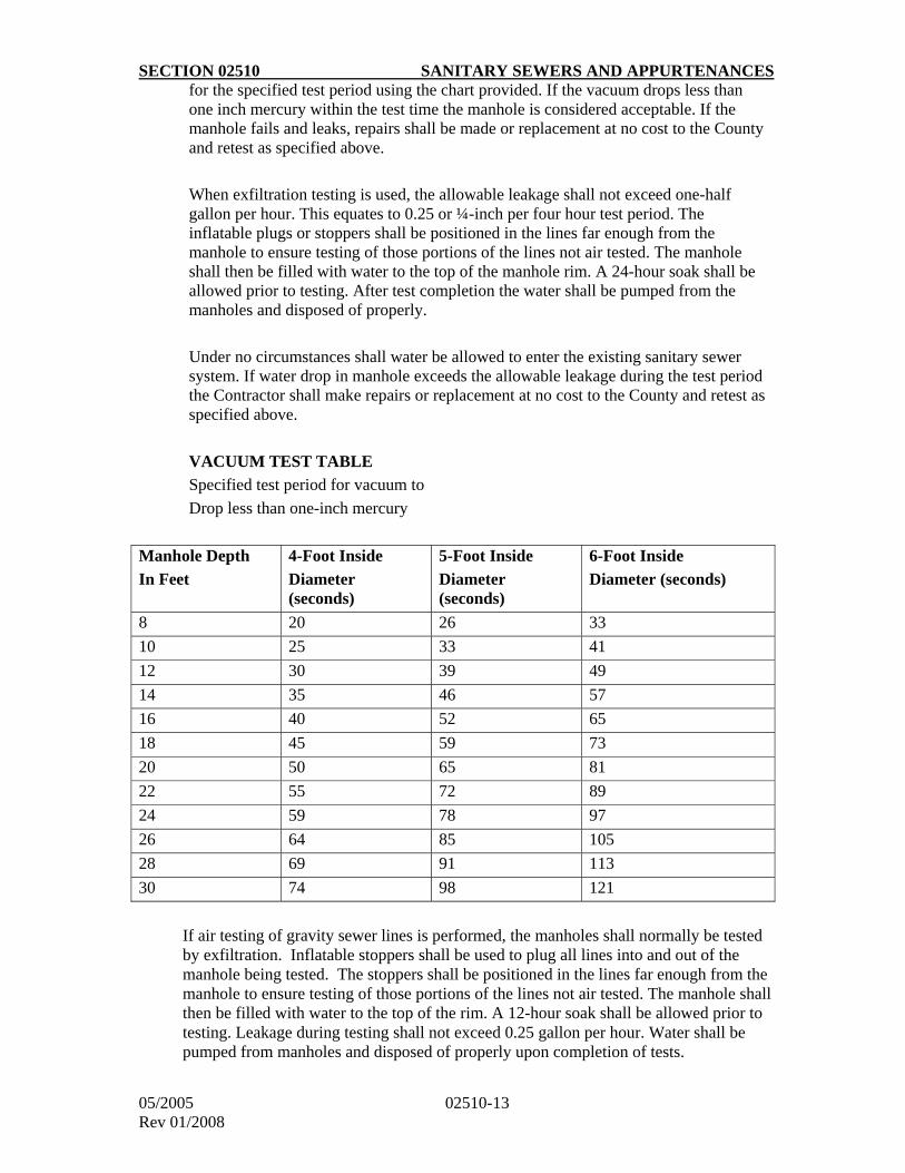
SECTION 02510 SANITARY SEWERS AND APPURTENANCES
05/2005 02510-13 Rev 01/2008
for the specified test period using the chart provided. If the vacuum drops less than one inch mercury within the test time the manhole is considered acceptable. If the manhole fails and leaks, repairs shall be made or replacement at no cost to the County and retest as specified above.
When exfiltration testing is used, the allowable leakage shall not exceed one-half gallon per hour. This equates to 0.25 or ¼-inch per four hour test period. The inflatable plugs or stoppers shall be positioned in the lines far enough from the manhole to ensure testing of those portions of the lines not air tested. The manhole shall then be filled with water to the top of the manhole rim. A 24-hour soak shall be allowed prior to testing. After test completion the water shall be pumped from the manholes and disposed of properly.
Under no circumstances shall water be allowed to enter the existing sanitary sewer system. If water drop in manhole exceeds the allowable leakage during the test period the Contractor shall make repairs or replacement at no cost to the County and retest as specified above.
VACUUM TEST TABLE
Specified test period for vacuum to
Drop less than one-inch mercury
Manhole Depth
In Feet
4-Foot Inside
Diameter (seconds)
5-Foot Inside
Diameter (seconds)
6-Foot Inside
Diameter (seconds)
8 20 26 33
10 25 33 41
12 30 39 49
14 35 46 57
16 40 52 65
18 45 59 73
20 50 65 81
22 55 72 89
24 59 78 97
26 64 85 105
28 69 91 113
30 74 98 121
If air testing of gravity sewer lines is performed, the manholes shall normally be tested by exfiltration. Inflatable stoppers shall be used to plug all lines into and out of the manhole being tested. The stoppers shall be positioned in the lines far enough from the manhole to ensure testing of those portions of the lines not air tested. The manhole shall then be filled with water to the top of the rim. A 12-hour soak shall be allowed prior to testing. Leakage during testing shall not exceed 0.25 gallon per hour. Water shall be pumped from manholes and disposed of properly upon completion of tests.
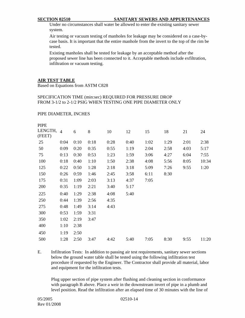
SECTION 02510 SANITARY SEWERS AND APPURTENANCES
05/2005 02510-14 Rev 01/2008
Under no circumstances shall water be allowed to enter the existing sanitary sewer system.
Air testing or vacuum testing of manholes for leakage may be considered on a case-by-case basis. It is important that the entire manhole from the invert to the top of the rim be tested.
Existing manholes shall be tested for leakage by an acceptable method after the proposed sewer line has been connected to it. Acceptable methods include exfiltration, infiltration or vacuum testing.
AIR TEST TABLE Based on Equations from ASTM C828
SPECIFICATION TIME (min:sec) REQUIRED FOR PRESSURE DROP FROM 3-1/2 to 2-1/2 PSIG WHEN TESTING ONE PIPE DIAMETER ONLY
PIPE DIAMETER, INCHES
PIPE LENGTH, (FEET)
4
6
8
10
12
15
18
21
24
25 0:04 0:10 0:18 0:28 0:40 1:02 1:29 2:01 2:38
50 0:09 0:20 0:35 0:55 1:19 2:04 2:58 4:03 5:17
75 0:13 0:30 0:53 1:23 1:59 3:06 4:27 6:04 7:55
100 0:18 0:40 1:10 1:50 2:38 4:08 5:56 8:05 10:34
125 0:22 0:50 1:28 2:18 3:18 5:09 7:26 9:55 1:20
150 0:26 0:59 1:46 2:45 3:58 6:11 8:30
175 0:31 1:09 2:03 3:13 4:37 7:05
200 0:35 1:19 2:21 3:40 5:17
225 0:40 1:29 2:38 4:08 5:40
250 0:44 1:39 2:56 4:35
275 0:48 1:49 3:14 4:43
300 0:53 1:59 3:31
350 1:02 2:19 3:47
400 1:10 2:38
450 1:19 2:50
500 1:28 2:50 3:47 4:42 5:40 7:05 8:30 9:55 11:20
E. Infiltration Tests: In addition to passing air test requirements, sanitary sewer sections below the ground water table shall be tested using the following infiltration test procedure if requested by the Engineer. The Contractor shall provide all material, labor and equipment for the infiltration tests.
Plug upper section of pipe system after flushing and cleaning section in conformance
with paragraph B above. Place a weir in the downstream invert of pipe in a plumb and level position. Read the infiltration after an elapsed time of 30 minutes with the line of
SECTION 02510 SANITARY SEWERS AND APPURTENANCES
05/2005 02510-15 Rev 01/2008
sight level to the weir line. Flow rates shall not exceed 100 gal./day/inch of diameter/mile. Readings that exceed 100 gal./day but are below 1,500 gal./day shall be remeasured using a weir with spout such as the –”Pomon-o-Weir” or equivalent.
F. Sanitary sewer force mains shall be hydrostatically tested, as described in Section 02550 Para. 3.4.H., at 150% of working pressure, 50 psig minimum.
G. Other Conditions: Sewer sections containing a large amount of lateral volume or sewer
sections partially submerged, shall be air-tested using the appropriate criteria stipulated in ASTM Designation C-828 to ensure accuracy of the test procedure.
H. T.V. Inspection: All new sanitary sewer main installations shall be required to pass a
T.V. inspection prior to final acceptance. The following items shall be completed before a T.V. inspection is scheduled with DES:
1. All manholes adjusted to finished grade.
2. Final paving completed.
3. All manholes are accessible to T.V. equipment.
4. All manholes and sanitary mains are free of dirt and debris.
5. All manhole inverts have been properly constructed to ensure smooth flow and positive drainage.
6. All lateral connections have been completed and accepted.
3.7 Protection of Water Supplies
There shall be no cross connection between a drinking water supply and any sewer, or appurtenance thereto.
3.8 Minimum Requirement for As-Built Plan
Upon completion of the construction of a sanitary sewer main project, one set of As-Built
mylar plans shall be furnished to DES for recording. The As-Built record drawings shall
include the following:
i) Invert elevation changes.
ii) Manhole top elevations.
iii) Change in percent of grade between manholes.
iv) Change in horizontal distance between manholes.
v) Any material changes.
vi) Location of connection to existing system from closest existing manhole.
vii) Location of sewer service connection from the closest manhole.
viii) Show actual location, depth or elevation, type and size of all utility crossings
PART 4 - MEASUREMENT AND PAYMENT
4.1 Sanitary Sewer
SECTION 02510 SANITARY SEWERS AND APPURTENANCES
05/2005 02510-16 Rev 01/2008
Sanitary sewer for the various sizes, classes, and depths shown on the bid proposal shall be measured in linear feet along the center line of the pipe and shall be measured from center of manhole to center of manhole. Payment shall include the furnishing of all pipe and fittings, all necessary tests, erosion and sediment control, excavation, supporting existing utilities, removal or abandoning of existing pipes and manholes, backfill, standard bedding, and all other work incidental to providing a complete sanitary sewer installation.
4.2 Sewer Service Connections
Sewer service connections shall be measured in linear feet along the center line of the main sewer, from the center line of main sewer to the end of the cap of where tied into the existing line. Payment for house connections shall include the plumbing permit, sewage excavation, backfill, tapping main sewer, pipe, fittings, and all cap work incidental to a complete and operable house connection.
4.3 Sanitary Sewer Force Mains
Sanitary sewer force mains shall be measured along the center line of the pipe and shall include fittings necessary for change in direction. Payment shall include the furnishing of all pipe and fittings, all necessary tests, erosion and sediment control, excavation, removal or abandonment of existing pipes, backfill, standard bedding, thrust blocks and anchorage and all other work incidental to providing a complete installation.
4.4 Manholes
Manholes shall be measured by the vertical foot from the invert of the outlet pipe to the top of the manhole cover. Payment shall include manhole, flexible sleeves, bedding base and channels, frame and cover (unless a separate pay item for frame and cover is called for in the proposal), intermediate landings as required, steps and all other work necessary for a complete installation.
4.5 Frame and Cover
When called out as a separate item in the proposal, frames and covers for the various sizes and types will be measured as each. Payment shall be at the unit price stated in the bid proposal and shall include all materials, labor and incidentals necessary for a complete installation.
4.6 Drop Connections
Drop connections for the various sizes and depths shown on the bid proposal shall be measured as each. Payment shall be at the unit price stated in the bid proposal and shall include all materials, labor and incidentals necessary for a complete and operable installation.
4.7 5-Foot and Larger Manhole Bases
5-foot and larger inside diameter manhole bases shall be measured as each. Payment shall include the additional costs required for furnishings and installing the larger manhole base and
SECTION 02510 SANITARY SEWERS AND APPURTENANCES
05/2005 02510-17 Rev 01/2008
incidentals in lieu of the standard 4-foot inside diameter manhole base. This payment will be in addition to the vertical foot measurement and payment for manholes.
4.8 Special Manholes and Structures
Special manholes and structures shall be measured as each. Payment shall be at the lump sum price for each special manhole or structure stated in the bid proposal and shall include all materials, labor and incidentals necessary for a complete installation.
4.9 Adjusting Existing Manholes to New Grades
Adjusting existing manhole tops to meet new grades, for the various types of adjustments indicated in the standard details, shall be measured as each. Payment shall be at the unit price stated for each type of adjustment indicated in the bid proposal and shall include all materials, labor and incidentals necessary for a complete installation.

SECTION 02550 WATER MAINS AND APPURTENANCES
05/2005 02550-1 Rev 01/2008
PART 1 - GENERAL
1.1 Description of Work
Provide all plant, labor, supervision, materials and equipment to install all water pipe and appurtenances to the lines and depths as called for on the approved plans and as described herein for a complete and operable water distribution system.
1.2 Related Work Specified Elsewhere
Section 02200 - Earthwork for Structures and Pipelines
Section 02950 - Tunneling
Section 02951 - Boring and Jacking
1.3 Applicable Specifications
A. American National Standards Institute (ANSI)
B. American Society for Testing and Materials (ASTM).
C. American Water Works Association (AWWA).
D. National Fire Protection Association (NFPA)
E. Arlington County Plumbing Code (Chapter 18 of the Arlington County Code).
F. Arlington County Utilities Code (Chapter 26 of the Arlington County Code).
G. Plumbing Code adopted by the State of Virginia
1.4 Applicable References
A. Erosion and Sediment Control Ordinance (Chapter 57 of the Arlington County
Code).
B. Virginia Department of Health (VDH) Waterworks Regulations (12 VAC 5-590)
1.5 Submittals
Submit full descriptions and details of all pipe, valves, hydrants, and other appurtenances proposed for the project to include an affidavit of compliance that all products meet the specifications herein. Any deviations from the drawings or specifications shall be clearly identified. Submit sworn statements from the manufacturers that the inspections and tests specified in the referenced standards have been made and that the results of such inspections and tests comply with the requirements of the applicable standard. Certificates of compliance and approval shall apply.
1.6 Quality Assurance
SECTION 02550 WATER MAINS AND APPURTENANCES
05/2005 02550-2 Rev 01/2008
A. The manufacturer shall provide facilities or a certified laboratory for conducting load bearing and other tests required by the referenced specifications such as the ASTM.
B. The Engineer will inspect pipe, fittings and joint material upon delivery to the
site. The Contractor shall provide ample space between rows of stockpiled pipe to facilitate adequate inspections.
PART 2 - MATERIALS
2.1 General
A. All materials shall be suitable for 150 pounds per square inch (psi) working
pressure unless otherwise indicated.
B. Pipe of the same size and material shall be furnished by the same manufacturer.
Each pipe length and fitting shall be clearly marked with the manufacturer's name, trademark and class of pipe.
C. Materials shall be recently manufactured and unused. Only previously approved
manufacturers items may be furnished.
2.2 Iron Pipe
A. Iron pipe shall be ductile iron conforming to AWWA C151 (ANSI A21.51),
class 53 minimum for 6-inch pipe and class 52 minimum for 8-inch and larger pipe. Pipe shall be single cement lined conforming to AWWA C104 (ANSI A21.4) and shall have mechanical or push-on joints utilizing rubber gasket rings, conforming to AWWA C111 (ANSI A21.11). Coatings shall be bituminous 1.0 mil. thick.
B. Fittings shall be mechanical joint ductile iron conforming to AWWA C110
(ANSI A21.10), with a minimum pressure rating of 250 psi, or ductile iron compact grade conforming to AWWA C-153 (ANSI 21.53) with a minimum pressure rating of 350 psi. Fittings shall be cement lined conforming to ANSI A21.4.
C. Polyethylene encasement with a minimum thickness of 8-mils shall be applied to all underground ductile pipe installations and shall comply with the installation and material requirements of AWWA C-105 and ANSI A21.5. All pipes, fittings, valves, hydrants and branch connections shall be encased as shown on approved plans. All holes and openings of any size shall be repaired in accordance with the manufacturer’s recommendations.
2.3 Concrete Pipe
Concrete pipe shall be reinforced prestressed, steel cylinder type conforming to AWWA C301, for the internal pressure and external loadings as indicated on the approved plans or special provisions.
SECTION 02550 WATER MAINS AND APPURTENANCES
05/2005 02550-3 Rev 01/2008
2.4 Tie Rods and Accessories for Anchorage and Mechanical Joint Restraints
Tie rods, tie bolts and accessories shall be manufactured of Cor-Ten corrosion resistant steel, ASTM-A242, Super Star series of Star National Products or approved equal.
Mechanical joint restraints shall be used with all water main appurtenances as directed or as approved by the engineer. Mechanical joint restraint shall be incorporated in the design of the follower gland and shall include a restraining mechanism which, when actuated imparts multiple wedging action against the pipe, increasing its resistance as the pressure increases. Restraining devices shall be manufactured of ductile iron. Torque limiting twist off nuts shall be used to insure proper installation of the restraining device. The minimum working pressure shall be at least 250 psi and shall be manufactured by EBAA iron, inc., MEGALUG or approved equal.
2.5 Gate Valves
A. Gate valves, 4-inch through 12-inch, for buried installation shall be iron body,
bronze mounted, resilient seated, O-ring sealed, non-rising stem, fitted with a 2-inch operating nut opening left, with mechanical joint and/or flanged ends, as indicated on the drawings. Valves shall conform to AWWA C-509 requirements. Provide buried valves with valve boxes. Provide extension stems extended within two feet of finished grade if required for valve depth. Valves shall be Mueller Co. No. A-2370-20, U.S. Pipe Metroseal valve, ITT Kennedy Ken-Seal valve, or approved equal.
B. Gate valves 14" and larger shall be iron body with fusion epoxy coating
conforming to AWWA C 550 bronze mounted, double disc, resilient wedge, O-ring sealed, non-rising stem, fitted with a 2" operating nut opening left, with mechanical joint and/or flanged ends as indicated on the drawings. 14" gate valves may be installed in vaults or buried with valve boxes and extension stems placed within two feet of finished grade if required for valve depth. Gate valves 16" and larger shall be installed in vaults with or without NRS bypass valve as indicated on the drawings. Valves shall conform to AWWA C-500 requirements and shall be Mueller Co. 2360 series or approved equal.
C. Gate valves 3" to 8" for water meter and/or fire line vault or interior installation shall be iron body, bronze mounted, resilient wedge , bolted bonnet, 250 psig maximum working pressure class 125 psi, outside screw and yoke, rising stem with hand wheel, opening left, with flanged ends. Valves shall be Mueller Co. 2360 series or approved equal.
D. Gate valves 2" and smaller shall be bronze body, solid disc, union bonnet, class 150 psi minimum, non-rising stem with hand wheel, opening left, with inside threaded ends. Valves shall be Stockham Model B-128 , Crane Model No. 426, or approved equal.
2.6 Butterfly Valves, Check Valves and Cone Valves

SECTION 02550 WATER MAINS AND APPURTENANCES
05/2005 02550-4 Rev 01/2008
Butterfly, check, and cone valves shall be as directed by the Engineer on a special project basis.
2.7 Fire Hydrants
Fire hydrants shall be dry top, dry barrel compression type, with a valve opening of 5-1/4
inches, double 0-ring seals and safety flange, and shall conform to AWWA C502 requirements. Hydrants shall be provided with two 2-1/2 inch hose nozzles and one 4-inch pumper nozzle with threading conforming to NFPA No. 194 requirements for National Standard Fire Hose Company Screw Threads, 6-inch mechanical joint inlet connection, National Standard 1-1/2 inch pentagon operating nut, outlet nozzle cap nuts, chains on outlet nozzle caps, and harnessed lugs. Hydrants shall open left and counterclockwise. Fire hydrants shall be painted with an exterior type industrial coating enamel. The upper barrel including bonnet and hose nozzle caps shall be painted "National Standard Yellow" using Duron Duraclad 12-10611 or approved equal. Hydrants shall be Mueller Super Centurion 250, American AVK or approved equal.
2.8 Valve Boxes
Valve boxes shall be of the two-piece, sliding type 5-1/4-inch shaft, cast iron kind. Valve box shall read “Water” Valve boxes shall be as manufactured by Bingham and Taylor Company or Tyler Company and conform to their standard dimensions.
2.9 Copper Pipe
Copper pipe shall be seamless water tube, AWWA type K conforming to ASTM designation B88 requirements. Fittings shall be underground copper service flared type.
2.10 Water Meters and Services by Arlington County
Water meters, including taps, pipe fittings, meter box and accessories from the water main
through the meter, will normally be furnished and installed by the Arlington County Department of Environmental Services (DES) after payment of the appropriate fee. The connection from the back side of the meter installation to the building shall be installed by the owner’s plumber.
2.11 Water Meters and Services by Contractor
The Department of Environmental Services shall approve all water meter locations. Water meters shall be located in the utility strip or just behind the curb within public right-of-way or recorded easements. A permanent clear space 5 foot by 5 foot shall be provided for each meter box.
The developer shall agree to assume complete responsibility for the installation, adjustments and any damage that may occur until final acceptance of the project.
New water mains shall pass all of acceptance testing procedures before the installation of water service connections.
SECTION 02550 WATER MAINS AND APPURTENANCES
05/2005 02550-5 Rev 01/2008
All services shall be installed by wet tap only. Service taps shall be located at the 10:00 and 2:00 position on the water main. Maintain a minimum of 12 inches between taps. Direct taps are allowed for ¾ inch and 1 inch connections. Use approved saddles for 1 ½ inch and 2 inch connections.
Water service lines shall have a minimum of three feet of cover and shall be approved by the engineer, from the main to the meter prior to backfilling. Meter settings for 1-inch to 2 inch services shall be a minimum of 18-inches and a maximum of 24-inches below the meter box cover. Meter box covers shall be painted black with an exterior type of rust resistant enamel.
Meter boxes, meter box covers, corporation stops, angle valves, yoke ells, yoke bars and all other appurtenances (except the water meter) necessary for a complete installation shall be provide in accordance with the approved plans, specifications and requirements of DES.
2.12 Air Release Valves
Air release valves shall be constructed of cast iron body and cover conforming to ASTM
A126.GR.B requirements. The float shall be stainless steel conforming to ASTM A240 requirements. Air release valves shall be manufactured by Apco, Crispin or approved equal.
2.13 Tapping Sleeves and Valves
Tapping sleeves and valves shall conform to the applicable requirements specified herein for installation on the existing type of pipe described below.
A. Iron Pipe: The tapping sleeve shall have an iron body, mechanical joint, with gaskets, suitable for installation on the existing iron pipe. The tapping sleeve shall be as manufactured by Mueller Company No. H-615 or approved equal. Tapping valves shall conform to the applicable requirements specified herein for gate valves as manufactured by Mueller Company No. T-2360 resilient wedge or approved equal. All stainless steel tapping sleeves shall be type 304 stainless steel with stainless steel flange and full circumferential seal as manufactured by JCM style 432 and Ford style FAST or approved equal.
B. Concrete Pipe: The tapping sleeve shall be in accordance with AWWA Manual M-9. The sleeves shall have a separate gland which permits installation of the sleeve prior to the cutting of the prestress wires. The gland shall have a fusion epoxy coated (per AWWA C-213-79) waterway, and a broad gasket set in a retaining groove of a draw flange to eliminate flexing. The gland shall be equipped with load bearing set screws to protect the cylinder. Sleeves shall be furnished with grouting seals and grout horns to facilitate filling the space between the sleeve and the pipe. Tapping sleeves shall be JCM 415 or approved equal.
2.14 Inserting Valves
Inserting valves shall conform to the specifications for gate valves. Valves may be double disc, AWWA C-500. Inserting valves 12-inches and smaller shall be No. H-800 as manufactured by Mueller Company. Inserting valves larger than 12-inches shall be as manufactured by A. P. Smith, or approved equal. Valve shall be suitable for installation on the existing pipe.
SECTION 02550 WATER MAINS AND APPURTENANCES
05/2005 02550-6 Rev 01/2008
2.15 Service Clamps
Service clamps shall have cadmium zinc plated be double steel straps and ductile iron body with corporation stop thread of appropriate size, neoprene gasket cemented in place, cadmium zinc plated nuts and straps and shall be the diameter required. Clamps shall be as manufactured by Ford, Mueller, Romac Industries, Smith Blair, JCM Industries or approved equal.
2.16 Manhole Frames and Covers
Manhole frames and covers shall be constructed of gray iron conforming to ASTM A-48
minimum class 30 requirements. Frames and covers shall have machined bearing surfaces to prevent rocking and rattling under traffic. Frames and covers shall conform to Arlington County Standards and Specifications as manufactured by Capitol Foundry or approved equal.
2.17 Manhole Steps
Manhole steps shall be a composite of a No. 3 grade 60 deformed steel bar encased in copolymer polypropylene plastic of the –“press-fit” design or rubber. Steps shall be PSI-PF as manufactured by M. A. Industries, Inc. or Wedge-Lok as manufactured by Delta Pipe Products, Inc. or approved equal.
PART 3 - EXECUTION
3.1 Water Main Design Criteria
Water mains shall be designed and installed to conform to Arlington County Standards and Specifications, the Virginia Department of Health Waterworks Regulations, American Water Works Association Standards and the following design criteria:
A. If required by DES, detailed design calculations shall be submitted to substantiate line sizes and to demonstrate that the minimum pressure of 20 psi, as stated in Section 12.10 of the Virginia Department of Health Waterworks Regulations, will be met for average daily demands, peak hourly demands, and maximum daily demand plus fire flow. The final size of all water mains and appurtenances shall be determined by DES.
B. The hydraulic conditions at the points of proposed connection of the existing Arlington County water system shall be defined. DES will provide the hydraulic conditions at the node closest to the point of connection (i.e., fire flow test results). The designer of the proposed water system shall model the water system network starting from the node of the water system for which Arlington County has supplied the starting hydraulic conditions. Requests for computer modeling or fire flow test information shall be addressed to DES. The request for computer modeling shall include a sketch plan indicating the location of proposed development, size of building, type of occupancy, number of occupants, estimated average daily demand, maximum daily demand, peak hourly demand and fire flow demand based on Insurance Services Office (ISO) requirements for all buildings within the proposed development (see Section 3.2 for fire flow requirement and Arlington County typical
SECTION 02550 WATER MAINS AND APPURTENANCES
05/2005 02550-7 Rev 01/2008
water demand rate). Required fire flow calculations shall be provided on the cover sheet of the approved plans.
C. Water mains shall be 6-inch diameter minimum and shall be looped wherever possible. Dead end mains shall not exceed 600 feet without approval from DES and shall have blow-offs or fire hydrants for flushing. No flushing device shall be directly connected to any sewer. No more than one fire hydrant shall be located on any 6-inch dead end main.
D. Water mains shall be located in street right of way and 7 feet off of face of curb
wherever possible. The water main shall extend the full frontage of the property being served unless directed otherwise by DES. Water mains shall not be located longitudinally under walks. Water mains, water meters, fire hydrants and blow offs shall be publicly maintained and as such shall be installed within recorded easements on private property when locations in public right of way are not possible. Such easements, measuring 20 feet in width, shall be recorded prior to final approval and issuance of building permits.
E. Water mains shall have a minimum cover of 4 feet measured from the top of pipe to the
proposed finished grade directly above the waterline; however, 3 feet minimum cover may be used for short distances to avoid utility conflicts and excessive depth of water main. Mains shall be laid on continuous grades to avoid sags or crests in the line.
F. The minimum clear horizontal separation between water mains and sewer mains or
sewer manholes shall be 10 feet (conforms to VDH Waterworks Regulation 12 VAC 5-590-1150). When local conditions prevent a minimum horizontal separation of 10 feet between water mains and sewer mains or sewer manholes, a closer separation may be allowed provided that:
1. Sewer manholes shall be of watertight construction and tested in place.
2. The bottom (invert) of the water main shall be a minimum of 18 inches above the top (crown) of the sewer. The water main and sewer pipes shall be kept in separate trenches. Where minimum vertical separation cannot be obtained, the sewer shall be constructed of ductile iron pipe and pressure tested in place without leakage prior to backfilling.
G. No water mains shall pass through or come in contact with any part of a sewer manhole.
H. Water mains crossing over sewers shall be laid to provide a minimum vertical
separation of 18 inches between the top of the sewer and the bottom of the water main. If local conditions prevent this, the water main shall be relocated to provide the separation directed by the Engineer, or the sewer shall be constructed of ductile iron pipe pressure tested in place without leakage before backfilling and with no joint of the sewer closer than 8 feet of the water main.
I. Water mains crossing under sanitary sewers shall be protected by the following
provisions:
SECTION 02550 WATER MAINS AND APPURTENANCES
05/2005 02550-8 Rev 01/2008
1. A minimum vertical separation of 18 inches between the top of the water main and the bottom of the sewer.
2. Sewer shall be constructed of ductile iron pipe, pressure tested in place without leakage before backfilling.
3. Adequate structural support for the sewer to prevent excessive joint deflection and the settling on and breakage of the water main. Refer to Standard Drawing M-7.0.
4. One length of the water pipe shall be centered at the point of crossing so that the joints are equidistant and as far as possible from the sewer.
J. Water mains crossing over surface waters shall be adequately supported, protected from freeze damage, accessible for repair or replacement, and above the 100-year flood elevation.
K. Water mains crossing under surface waters shall be protected by the following
provisions:
1. The pipe shall be of special construction, having flexible watertight joints.
2. Valves shall be provided at both ends of the water crossing so that the section can be isolated for tests or repair; the valves shall be easily accessible and not subject to flooding.
3. Sample taps shall be available at each end of the crossing at a reasonable distance from each side of the crossing and not subject to flooding.
4. Permanent taps shall be made for testing and locating leaks.
L. The minimum clear horizontal separation between water main and utilities other than sanitary sewer shall be 5 feet (see 3.1.F for separation between water main and sanitary sewer).
M. The minimum vertical clearance between water main and utilities other than sanitary sewer shall be 1.0 foot, unless provisions to prevent damage to the underlying utility are detailed for approval by DES.
N. The minimum horizontal separation between water main and buildings or other
structures shall be provided as follows:
1. Ten feet for water mains less than 16 inches and 10 feet or less in depth.
2. Fifteen feet for water mains 16 inches and larger or all mains in excess of 10 feet in depth.
3.
O. Valves shall be provided on all mains at major intersections and on branch mains at minor intersections. Four valves are required at crosses and three at tees unless otherwise approved by DES. Line valve spacing shall be 500 feet maximum for water
SECTION 02550 WATER MAINS AND APPURTENANCES
05/2005 02550-9 Rev 01/2008
mains 12 inches and smaller and as determined by DES for mains larger than 12 inches. Valve boxes shall be set and adjusted flush with the roadway surface. Where valves boxes are located in off street areas they shall be set flush in a 2’ x 2’ x 6” concrete pad.
P. Automatic air release valves shall be installed on water mains according to the following provisions (conforming to VDH Waterworks Regulation 12 VAC 5-590-1160):
1. Air release valves shall be located at "strategic" high points as directed or approved
by DES.
2. Refer to the standard drawings for air release valve settings.
3. Air release valve and piping shall be two inches unless directed or approved otherwise by DES.
4. Air release valves shall not be located in areas subject to flooding or high water table. In cases where such locations cannot be avoided, sump pumps and special vent piping shall be required as directed by DES.
5. Tapping saddles shall be used.
6. Chambers containing air release valves shall not be connected directly to any storm drain or sanitary sewer, nor shall air release valves be connected directly to any sewer. Chambers shall be drained to the surface of the ground where they are not subject to flooding by surface water or to absorption pits located above the seasonal groundwater table elevation. Sump pumps may be used where other means are not practical.
Q. Water services shall be located behind the curb line and clear of driveways and other vehicular traffic areas. A clear space 5 feet by 5 feet shall be permanently provided for 2 inch and smaller water meters. A clear space 20 feet by 15 feet and 10 feet deep shall be permanently provided behind the curb for 3- and 4-inch water meter vault installations. A clear space 25 feet by 20 feet and 10 feet deep shall be provided for 6-and 8-inch meter vault installations. Water meters sizes greater than 8-inches shall be approved by DES.
R. No water service taps shall be made without special approval from DES in transmission mains 16 inches and larger.
S. Backflow prevention devices shall be installed at each service connection to a consumer's water system when specified by the Arlington County Department of Community Planning, Housing & Development (DCPHD) - Inspection Services Division that a potential health, pollution or system hazard to the waterworks exists. Refer to the Arlington County Cross Connection and Backflow Prevention Control Ordinance for more information.
SECTION 02550 WATER MAINS AND APPURTENANCES
05/2005 02550-10 Rev 01/2008
T. All plans and specifications for construction of proposed water distribution facilities must be approved by DES. No water distribution facility shall be constructed without approved plans, shop drawings and construction cut sheets.
U. All existing segments of water main to be cut and capped shall be strapped or thrust
blocked as directed by DES.
V. Blow offs for water mains shall be provided at all “strategic” low points and all
terminal points. Fire hydrants may be used in lieu of blow offs as directed by DES. Blow offs shall be installed in meter boxes and located behind the curb line and clear of driveways and other vehicular traffic areas (refer to Standard Drawing W-4.0).
3.2 Fire Protection Requirements
Waterworks systems shall be designed to deliver a minimum residual pressure of 20 psi with fire flow requirements and maximum daily demands applied to the system. Applicable fire flow shall be selected based on the Insurance Services Office (ISO) methodology with a maximum sprinkler protection credit of 50% reduction for buildings with fully automated sprinkler monitor systems.
All fire flow requirements shall be computed as set forth in Part A. below. However, in general, the requirements are as follows:
(1) Single-family dwellings - minimum exposure distances of:
less than 10' 1500 - 2000 gallons per minute (gpm)
10' - 30' 1000 - 1500 gpm
greater than 30' 1000 gpm
(2) Townhouses or multiplex units - residential or commercial l2500 gpm (3) Other uses - fire flow requirements computed as set forth below.
A. Computation of “Needed Fire Flow”
This item sets forth the Needed Fire Flows for selected locations throughout the County which are used in the review of plans. The calculation of a Needed Fire Flow (NFF) for a subject building in gallons per minute (gpm) considers the Construction (Ci), Occupancy (Oi), Exposure (Xi), and Communication (Pi) of each selected building, or fire division, as outlined below. This method shall not apply to single family detached dwellings.
1. Construction Factor (Ci):
That portion of the Needed Fire Flow attributed to the Construction and area of the selected building is determined by the following formula:
Ci=18F (Ai)0.5, where
F=Coefficient related to the class of construction:
F=1.5 for Construction Class 1 (Frame)
Frame Construction--Any structure in which the structural members are wholly or partly of wood or other combustible material and the construction does not qualify as ordinary construction.
SECTION 02550 WATER MAINS AND APPURTENANCES
05/2005 02550-11 Rev 01/2008
F=1.0 for Construction Class 2 (Joisted Masonry)
Joisted Masonry--Any structure having exterior walls of masonry or other non-combustible material in which the other structural members, including but not limited to columns, floors, roofs, beams, girders, and joists, are wholly or partly of wood or other combustible material.
F=0.8 for Construction Class 3 (Noncombustible) and Construction Class 4(Masonry Noncombustible) Noncombustible Construction--Any structure having all structural members including walls, columns, piers, beams, girders, trusses, floors, and roofs of noncombustible material and not qualifying as fire resistive construction.
F=0.6 for Construction Class 5 (Modified Fire Resistive) and Construction Class 6(Fire Resistive) Fire Resistive Construction--Any structure that is considered fire resistive by any of the BOCA building codes.
Ai=Effective area
Area in square feet of the largest Fire Division of the building.
In buildings with mixed construction a value, Cim, shall be calculated for each class of construction using the effective area of the building. These Cim values are multiplied by their individual percentage of the total area. The Ci applicable to the entire building is the sum of these values. However, the value of the Ci shall not be less than the value for any part of the building based upon its own construction and area. The maximum value of Ci is limited by the following:
8,000 gpm for Construction Classes 1 and 2
6,000 gpm for Construction Classes 3, 4, 5, and 6
6,000 gpm for a 1-story building of any class of construction.
The minimum value of Ci is 500 gpm. The calculated value of Ci shall be rounded to the nearest 250 gpm.
2. Occupancy Factor (Oi)
The factors below reflect the influence of the occupancy in the selected building on the Needed Fire Flow.
Occupancy Combustibility Class Occupancy Factor (Oi)
C-1 (Noncombustible) 0.75
C-2 (Limited Combustible) 0.85
C-3 (Combustible) 1.00
C-4 (Free Burning) 1.15
C-5 (Rapid Burning) 1.25
3. Exposures (Xi) and Communication (Pi) Factors
The factors developed in this item reflect the influence of exposed and communicating buildings on the Needed Fire Flow. A value for (Xi+Pi) shall be developed for each side of the subject building:
1, maximum 1.75, where n=number of sides of subject building.
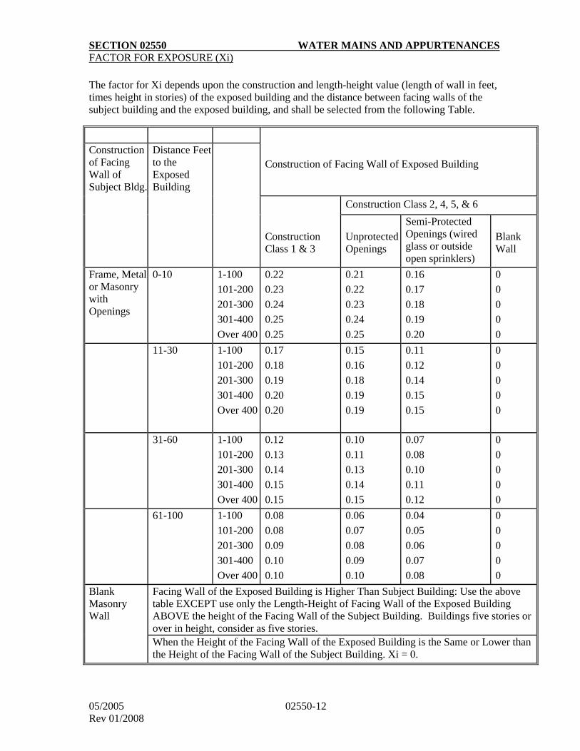
SECTION 02550 WATER MAINS AND APPURTENANCES
05/2005 02550-12 Rev 01/2008
FACTOR FOR EXPOSURE (Xi)
The factor for Xi depends upon the construction and length-height value (length of wall in feet, times height in stories) of the exposed building and the distance between facing walls of the subject building and the exposed building, and shall be selected from the following Table.
Construction of Facing Wall of Exposed Building Construction of Facing Wall of Subject Bldg.
Distance Feet to the Exposed Building
Construction Class 2, 4, 5, & 6
Construction Class 1 & 3
Unprotected Openings
Semi-Protected Openings (wired glass or outside open sprinklers)
Blank Wall
Frame, Metal or Masonry with Openings
0-10 1-100
101-200
201-300
301-400
Over 400
0.22
0.23
0.24
0.25
0.25
0.21
0.22
0.23
0.24
0.25
0.16
0.17
0.18
0.19
0.20
0
0
0
0
0
11-30 1-100
101-200
201-300
301-400
Over 400
0.17
0.18
0.19
0.20
0.20
0.15
0.16
0.18
0.19
0.19
0.11
0.12
0.14
0.15
0.15
0
0
0
0
0
31-60 1-100
101-200
201-300
301-400
Over 400
0.12
0.13
0.14
0.15
0.15
0.10
0.11
0.13
0.14
0.15
0.07
0.08
0.10
0.11
0.12
0
0
0
0
0
61-100 1-100
101-200
201-300
301-400
Over 400
0.08
0.08
0.09
0.10
0.10
0.06
0.07
0.08
0.09
0.10
0.04
0.05
0.06
0.07
0.08
0
0
0
0
0
Blank Masonry Wall
Facing Wall of the Exposed Building is Higher Than Subject Building: Use the above table EXCEPT use only the Length-Height of Facing Wall of the Exposed Building ABOVE the height of the Facing Wall of the Subject Building. Buildings five stories or over in height, consider as five stories. When the Height of the Facing Wall of the Exposed Building is the Same or Lower than the Height of the Facing Wall of the Subject Building. Xi = 0.
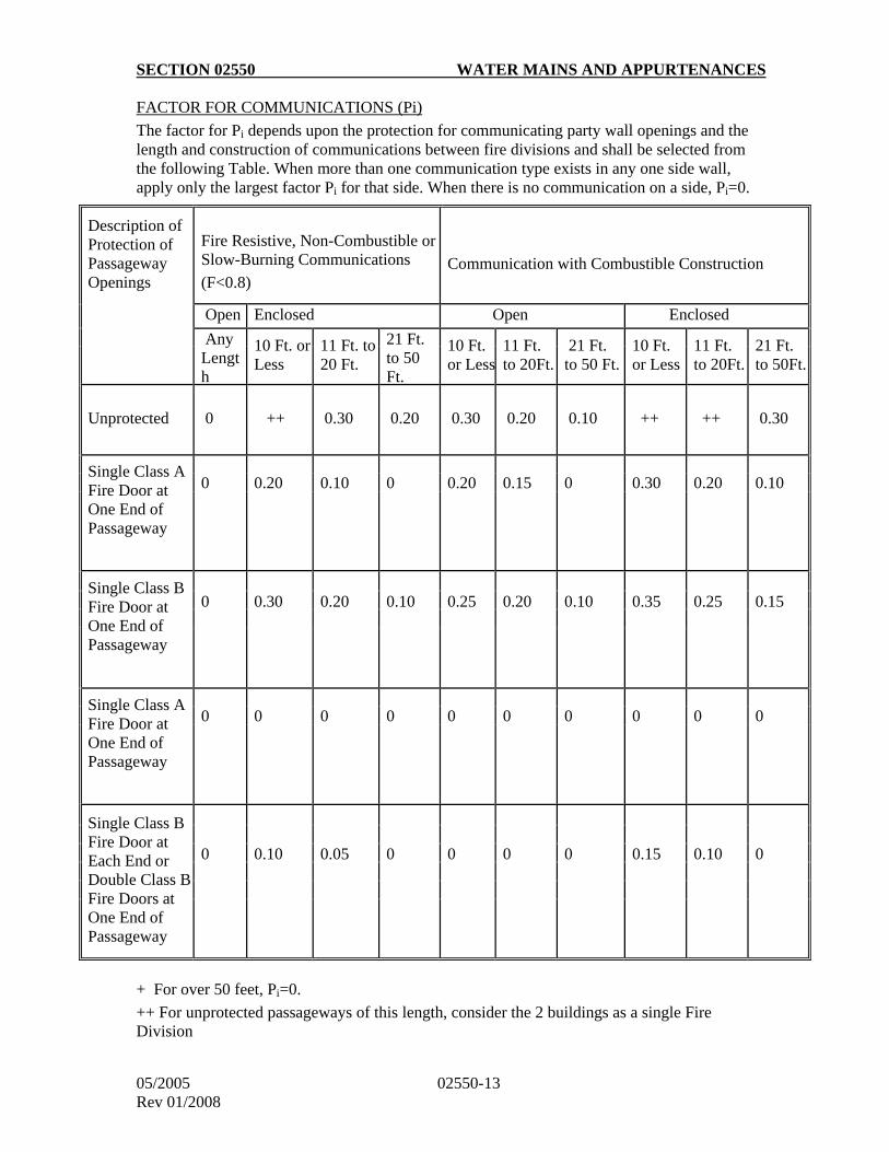
SECTION 02550 WATER MAINS AND APPURTENANCES
05/2005 02550-13 Rev 01/2008
FACTOR FOR COMMUNICATIONS (Pi)
The factor for Pi depends upon the protection for communicating party wall openings and the length and construction of communications between fire divisions and shall be selected from the following Table. When more than one communication type exists in any one side wall, apply only the largest factor Pi for that side. When there is no communication on a side, Pi=0.
+ For over 50 feet, Pi=0.
++ For unprotected passageways of this length, consider the 2 buildings as a single Fire Division
Description of Protection of Passageway Openings
Fire Resistive, Non-Combustible or Slow-Burning Communications
(F<0.8)
Communication with Combustible Construction
Open Enclosed Open Enclosed
Any Length
10 Ft. or Less
11 Ft. to 20 Ft.
21 Ft. to 50 Ft.
10 Ft. or Less
11 Ft. to 20Ft.
21 Ft. to 50 Ft.
10 Ft. or Less
11 Ft. to 20Ft.
21 Ft. to 50Ft.
Unprotected
0 ++ 0.30 0.20 0.30 0.20 0.10 ++ ++ 0.30
Single Class A Fire Door at One End of Passageway
0 0.20 0.10 0 0.20 0.15 0 0.30 0.20 0.10
Single Class B Fire Door at One End of Passageway
0 0.30 0.20 0.10 0.25 0.20 0.10 0.35 0.25 0.15
Single Class A Fire Door at One End of Passageway
0 0 0 0 0 0 0 0 0 0
Single Class B Fire Door at Each End or Double Class B Fire Doors at One End of Passageway
0 0.10 0.05 0 0 0 0 0.15 0.10 0
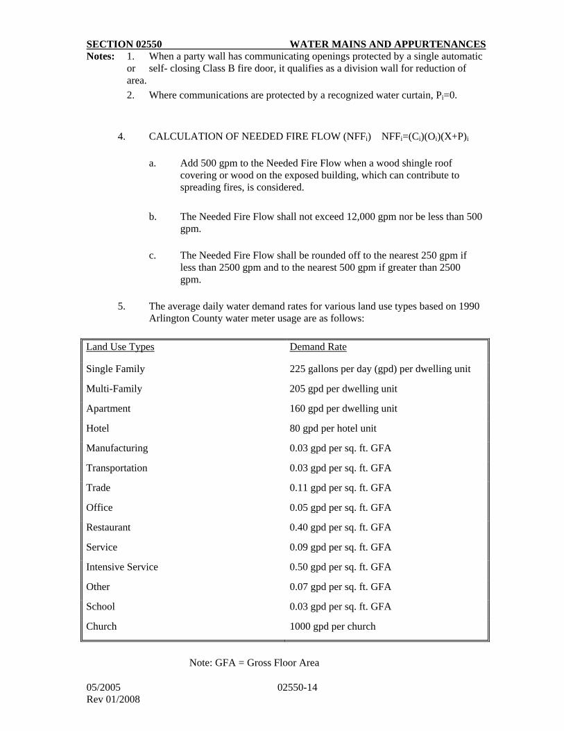
SECTION 02550 WATER MAINS AND APPURTENANCES
05/2005 02550-14 Rev 01/2008
Notes: 1. When a party wall has communicating openings protected by a single automatic or self- closing Class B fire door, it qualifies as a division wall for reduction of area.
2. Where communications are protected by a recognized water curtain, Pi=0.
4. CALCULATION OF NEEDED FIRE FLOW (NFFi) NFFi=(Ci)(Oi)(X+P)i
a. Add 500 gpm to the Needed Fire Flow when a wood shingle roof
covering or wood on the exposed building, which can contribute to spreading fires, is considered.
b. The Needed Fire Flow shall not exceed 12,000 gpm nor be less than 500 gpm.
c. The Needed Fire Flow shall be rounded off to the nearest 250 gpm if
less than 2500 gpm and to the nearest 500 gpm if greater than 2500 gpm.
5. The average daily water demand rates for various land use types based on 1990
Arlington County water meter usage are as follows:
Land Use Types Demand Rate
Single Family 225 gallons per day (gpd) per dwelling unit
Multi-Family 205 gpd per dwelling unit
Apartment 160 gpd per dwelling unit
Hotel 80 gpd per hotel unit
Manufacturing 0.03 gpd per sq. ft. GFA
Transportation 0.03 gpd per sq. ft. GFA
Trade 0.11 gpd per sq. ft. GFA
Office 0.05 gpd per sq. ft. GFA
Restaurant 0.40 gpd per sq. ft. GFA
Service 0.09 gpd per sq. ft. GFA
Intensive Service 0.50 gpd per sq. ft. GFA
Other 0.07 gpd per sq. ft. GFA
School 0.03 gpd per sq. ft. GFA
Church 1000 gpd per church
Note: GFA = Gross Floor Area
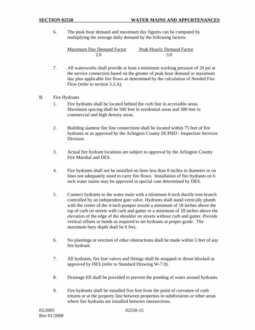
SECTION 02550 WATER MAINS AND APPURTENANCES
05/2005 02550-15 Rev 01/2008
6. The peak hour demand and maximum day figures can be computed by multiplying the average daily demand by the following factors:
Maximum Day Demand Factor Peak Hourly Demand Factor 2.0 3.0
7. All waterworks shall provide at least a minimum working pressure of 20 psi at the service connection based on the greater of peak hour demand or maximum day plus applicable fire flows as determined by the calculation of Needed Fire Flow (refer to section 3.2.A).
B. Fire Hydrants
1. Fire hydrants shall be located behind the curb line in accessible areas. Maximum spacing shall be 500 feet in residential areas and 300 feet in commercial and high density areas.
2. Building siamese fire line connections shall be located within 75 feet of fire hydrants or as approved by the Arlington County DCPHD - Inspection Services Division.
3. Actual fire hydrant locations are subject to approval by the Arlington County Fire Marshal and DES.
4. Fire hydrants shall not be installed on lines less than 8 inches in diameter or on lines not adequately sized to carry fire flows. Installation of fire hydrants on 6 inch water mains may be approved in special case determined by DES.
5. Connect hydrants to the water main with a minimum 6-inch ductile iron branch controlled by an independent gate valve. Hydrants shall stand vertically plumb with the center of the 4-inch pumper nozzle a minimum of 18 inches above the top of curb on streets with curb and gutter or a minimum of 18 inches above the elevation of the edge of the shoulder on streets without curb and gutter. Provide vertical offsets or bends as required to set hydrants at proper grade. The maximum bury depth shall be 6 feet.
6. No plantings or erection of other obstructions shall be made within 5 feet of any fire hydrant.
7. All hydrants, fire line valves and fittings shall be strapped or thrust blocked as approved by DES (refer to Standard Drawing W-7.0).
8. Drainage fill shall be provided to prevent the ponding of water around hydrants.
9. Fire hydrants shall be installed five feet from the point of curvature of curb returns or at the property line between properties in subdivisions or other areas where fire hydrants are installed between intersections.
SECTION 02550 WATER MAINS AND APPURTENANCES
05/2005 02550-16 Rev 01/2008
10. Fire hydrants shall be drained to dry wells provided exclusively for this purpose.
11. Fire hydrants shall not be located in areas subject to high groundwater, flooding, contaminant or pollutant spills, or in areas where surface water ponds. If there exist no alternative location, weepholes on the hydrant shall be plugged and the hydrant shall be marked for seasonal dewatering or the weephole drainage shall be piped to daylight with the pipe end screened.
12. Fire hydrants shall be placed so that the top operating nut is a minimum of 18 inches and a maximum of 2 feet back from the face of curb unless otherwise directed by the Arlington County Fire Marshal or DES.
13. Fire hydrants shall be installed within recorded easements on private property when locations in public right of way are not possible.
3.3 Minimum Requirement for As-Built Plan
Upon completion of the construction of a water main project, one set of As-Built mylar plans shall be furnished to the Arlington County Department of Environmental Services for recording. The As-Built record drawings shall include the following:
i) Changes in valve and fire hydrant locations.
ii) Horizontal line changes and/or location of water main appurtenances changes.
iii) no changes in water main profiles greater than 6-inches.
iv) Actual materials, limits of mechanical joint restraints and location of reaction blocking used on the project.
v) Water main to meter distances and locations of all water service meters and water service lines.
vi) Show actual location, depth or elevation, type and size of all utility crossings.
vii) Provide a minimum of two (2) swing ties to all valve boxes and permanent blowoffs from fixed permanent objects visible above snow cover such as fire hydrants, utility poles or building corners. Swing ties shall cross as near to ninety degrees as practical for each valve box and blowoff located.
viii) Statement from the design engineer that the As-Built construction record drawings are in substantial conformance with the associated design drawings unless otherwise noted on the as-built plans.
3.4 Construction Standards
SECTION 02550 WATER MAINS AND APPURTENANCES
05/2005 02550-17 Rev 01/2008
A. Laying Pipe
1. Use proper and suitable tools for the safe handling and laying of pipes and fittings. Prevent fitting linings and coatings from being damaged; damaged pipe shall be replaced or repaired to the satisfaction of the Engineer.
2. Unless indicated otherwise, the depth of trench shall be sufficient to provide a minimum cover over the top of the pipe of 4.0 feet from the existing or proposed ground surface and to avoid interference of the pipeline with other utilities. Install pipe on continuous grades, as indicated on plans, to avoid sags or crests in the line.
3. The cutting of pipe for inserting valves, fittings, or closure pieces shall be done in a neat and workmanlike manner, without damage to the pipe, so as to leave a smooth end at right angles to the axis of the pipe. Outside edge of cut pipe shall be beveled and smoothed to avoid damage to the gasket. Avoid damage to the lining. Do not flame cut cast iron pipe with oxyacetylene torch.
4. Thoroughly clean pipes and fittings before they are laid.
5. Carefully lower pipe fittings into trench. Butt ends of pipe against each other in such a manner that there shall be no shoulder or unevenness on the inside of the pipe.
6. Ensure that pipe is well bedded on a solid foundation as shown in the standard details. Correct any defects due to settlement. Excavate bell holes sufficiently large to ensure making proper joints. Exercise precautions to include the furnishing and placing of aggregate to prevent any pipe from resting directly on rock. Rock found in trench shall be removed to provide a clearance of at least six inches below and on each side of all pipe, valves and fittings and shall be replaced with select fill.
7. Iron pipe shall be jointed in full accordance with AWWA Standard C600, the manufacturer's recommendations and the following requirements:
a. Push-on joints shall be thoroughly cleaned. Brush-coat gasket retaining groove with approved gasket lubricant and insert the rubber gasket in the bell socket. Apply a thin film of approved gasket lubricant to the exposed gasket surface. Clean and center the spigot end of the pipe into the socket complete the joint by forcing the spigot end to the bottom of the socket.
b. Mechanical joints shall be thoroughly cleaned. Lubricate the gasket and spigot. Place the gland on the spigot end, followed by the gasket, and the pipe end seated and centered in the socket. The gasket shall then be seated in the sockets, gland moved into position and bolts and nuts loosely assembled by hand. Tighten with a wrench.
SECTION 02550 WATER MAINS AND APPURTENANCES
05/2005 02550-18 Rev 01/2008
8. Reinforced concrete pipe joints shall be thoroughly cleaned. Swab a full coating of approved lubricant into the bell socket. Immerse the rubber gasket in lubricant and stretch into position on the spigot end. Center the spigot end into the socket and force it into the socket. Place a cloth band around the joint. Pour a mortar grout into the joint recess and work so as to fill the entire recess around the pipe. Complete the joint by filling the inside joint recess with mortar troweled flush with the interior surface.
9. At the close of work each day, close end of the pipeline with an expansion stopper so that no dirt or other foreign substance may enter the line. Keep this stopper in place until pipe laying is resumed.
10. Remove and replace all defective materials at no additional cost to the County.
B. Connections to Existing Mains
1. Notify the Engineer two (2) working days prior to scheduling work on existing water mains (notify Engineer on Thursday before proposed Monday work). No connections shall be scheduled for the day before weekends and holidays. Connect new water mains to the existing mains as shown on the drawings. Verify the location, type of pipe and size of the existing main well in advance of any work on the connection. The Contractor shall give DES at least five (5) days notice of the need to shut down existing water mains so that DES may give advanced notice to the affected customers. Shutdowns in service, where permitted, and operation of any valves on the existing system shall be done only by DES. To minimize shutdown time, connections to water lines shall be made by the Contractor only after complete preparations for such work have been done to the satisfaction of the Engineer.
2. Reaction backing at connections to existing mains shall be made with high early strength concrete. In the event that line pressure must be restored less than 48 hours after the placement of reaction backing at these connections, provide temporary deadman and/or similar devices as required to maintain stability of the water mains.
C. Installing Valves and Fittings
1. Install valves, fittings, and caps to pipe in the manner herein before specified for laying pipe. Provide valve boxes for each buried gate valve. Boxes shall not transmit shock or stress to the valve. Center and plumb boxes over the operating nut of the valve, with the box cover flush. Valves shall be strapped to adjacent fittings unless directed otherwise.
2. Inserting valves and tapping sleeves and valves shall be installed in
accordance with the valve manufacturer's recommendations. Test pits shall be dug by the Contractor to determine type and size of existing pipe and suitability of tapping location on the pipe.
SECTION 02550 WATER MAINS AND APPURTENANCES
05/2005 02550-19 Rev 01/2008
D. Thrust Restraint
Provide caps, tees, bends and inserting valves in water mains with reaction backing and other joint restraints such as "MEGALUG", manufactured by EBAA Iron, Inc., or approved equal, except where tie rods are specified or indicated. Reaction backing shall consist of concrete thrust blocks as shown on the Standard Details. Valves for connections to future lines, fire hydrants and related valves, and other fittings or valves so indicated shall be anchored by steel rods protected by two coats of acid-resisting asphalt paint.
The use of reaction backing may be waived in the sole discretion of DES if the designer provides calculations to indicate an adequate number of joints are restrained in proximity to caps, tees, bends and inserting valves. The limits of restraints shall be indicated clearly on the approved plans.
E. Water Service Connections
Water mains shall pass all acceptance testing procedures before installation of water service connections. Water service connections from the water mains through the water meters will be furnished and installed by DES unless indicated otherwise on the approved plans. Where water services are installed by the Contractor, the Contractor shall give the Engineer three (3) working days notice prior to the start of work. Connections from the meter installation to the building shall be installed by the building owner's plumber.
F. Abandoning Existing Water Mains
1. Drain and abandon existing water mains not required in the completed system. Abandoned mains and appurtenances that conflict with proposed construction shall be removed as required. Abandoned mains not removed shall be capped or bulk headed at all open ends. Boxes on abandoned valves shall be removed.
2. Cut and cap the existing water mains to remain in service at the locations indicated on the drawings, and provide with reaction backing. Keep the length of pipe removed to the minimum necessary for installing the cap and concrete blocking. A cap or concrete bulkhead shall be placed over the end of the pipe to be abandoned. The concrete thrust block shall be placed to bear against undisturbed ground. After this work has been completed, the capped line shall not be recharged unless so directed by the Engineer.
3. Existing fire hydrants not required in the completed system shall be carefully removed, cleaned and transported to the County storage yard. Cap and anchor hydrant lead as close as possible to its control valve with concrete thrust block and tie rods if main is to remain in service.
4. Existing water services shall be discontinued by DES unless a written request is provided to DES for the temporary use of the service during construction. Water meter boxes and vaults shall be removed by the
SECTION 02550 WATER MAINS AND APPURTENANCES
05/2005 02550-20 Rev 01/2008
Contractor. Water meters will be removed by DES as required. No credit or allowance will be given for discontinued water services.
G. Disinfection of Water Mains
1. When each pipe length has been placed and shut off, disinfect each section of the water main. Provide all labor, materials and equipment to perform the disinfection operations in compliance with all state and local regulations. Disinfection shall conform to AWWA C601 requirements.
2. Water for disinfection, flushing and testing will be furnished to the
Contractor from the existing water system at no charge to the Contractor. Schedule water usage with the Engineer to result in a minimum interference to water service throughout the existing water system. Temporary connections to the existing water system shall be provided and removed by the Contractor and shall include approved means to prevent backflow and possible contamination of the existing water system. Temporary taps for removing air and flushing the main shall be provided by the Contractor as necessary.
3. Disinfection of the water main shall be accomplished in the following manner:
a. Preliminary Flushing of Mains: All mains shall be flushed prior to disinfection except when the tablet method of disinfection is used. The mains shall be flushed at a minimum velocity of 2.5 feet per second and all points in the main shall receive a minimum of five (5) consecutive minutes of flushing at this velocity, until the water runs clear.
b. Form of Chlorine to be Used: Liquid chlorine, calcium hypochlorite or sodium hypochlorite may be used for disinfection. Liquid chlorine shall be used only when approved by the Engineer. Calcium hypochlorite and sodium hypochlorite shall be added to water to form a chlorine water solution before being used.
c. Methods of Application: The chlorine shall be applied by continuous feed method or by the tablet method only (slug method shall not be used). The application shall be performed as follows:
a) Continuous Feed Method: Potable water shall be introduced into the pipe line at a constant flow rate. Chlorine shall be added at a constant rate to this flow so that the chlorine concentration in the water in the pipe is at least 50 mg/L. The chlorinated water shall remain in the pipe at least 24 hours, after which, the chlorine concentration in the water shall be at least 10 mg/L.
SECTION 02550 WATER MAINS AND APPURTENANCES
05/2005 02550-21 Rev 01/2008
b) Tablet Method: Tablet method shall not be used if trench water or foreign material has entered the main or if the water is below 5oC (41oF). Tablets are placed in each section of pipe and also in hydrant branches and other appurtenances. A sufficient number of tablets shall be used to ensure that a chlorine concentration in the water in the pipe is at least 25 mg/L. The tablets shall be attached by an adhesive to the top of the pipe sections and crushed or rubbed in all appurtenances. The adhesive shall be acceptable to the Virginia Department of Health (VDH). When installation has been completed, the main shall be filled with water at a velocity of less than one foot per second. The water shall then remain in contact with the pipe for at least 24 hours.
d. Contact Period: The chlorinated water shall be retained in the main for at least 24 hours during which time all valves and hydrants, in the section treated, shall be operated in order to disinfect the appurtenances. The tests for chlorine residual shall be made by the Engineer. The Contractor shall install corporation cocks and copper tubing for the tests at the locations indicated by the Engineer.
e. Flushing and Discharge: After the applicable retention period, the heavily chlorinated water shall be flushed from the main until the chlorine concentration in the water leaving the main is no higher than that generally prevailing in the system or less than 1 mg/l. Chlorine residual determination shall be made by the Engineer. The Contractor shall assume full responsibility for the lawful disposal of chlorinated water. Any damage to property vegetation, trees, streams or ponds caused by the discharge of heavily chlorinated water or injury to customers resulting from the discharge of disinfected water into the system shall be the responsibility of the Contractor and shall be remedied at the Contractor's expense. Hydrostatic testing shall not be performed until the requirements of this section have been completed successfully.
H. Hydrostatic Testing
1. Pressure tests shall conform with Section 4 of AWWA Standard C600.
2. The water mains shall be tested for leakage by the Contractor at his own expense in the presence of the Engineer. All tests will be conducted in a manner to minimize any interference with the Contractor's work or progress. A maximum of 2,000 linear feet of water main may be tested at one time.
3. The Contractor shall notify the Engineer when the work is ready for hydrostatic testing and tests shall be taken soon thereafter as practicable under the direction of the Engineer. Personnel for reading meters,
SECTION 02550 WATER MAINS AND APPURTENANCES
05/2005 02550-22 Rev 01/2008
gauges or other measuring devices will be furnished by the Engineer, but all other labor, equipment, water and materials, excluding meters and gauges, shall be furnished by the Contractor.
4. The water mains, including all appurtenances, shall be tested as a whole or in sections, valved or bulkhead at the ends. Test piping under a hydrostatic pressure of 200 psig unless shown otherwise on the approved plans. Testing shall not be conducted against existing valves. Apply pressure to the piping after it has been purged of air. Maintain water pressure for a minimum of two hours. The test pressure shall not vary by more than 5 psi during the test. Testing procedures shall be in accordance with AWWA Standard C600 with the exception that in no case shall the measured leakage exceed 10 gallons/ inch of diameter/mile/day.
I. Final Flushing
All water mains shall be flushed after the acceptance of the hydrostatic test and before bacteriologic testing. The water mains shall be flushed at the highest flow possible through hydrants and/or blow-offs. The operation of any valves on the existing water system shall be done only by DES.
J. Bacteriologic Test
1. After chlorination, hydrostatic testing and final flushing, and before the water main is placed in service, samples shall be collected from the main and tested for enteric bacterial contamination and shall show the absence of coliform organisms. At least two (2) sets of consecutive satisfactory bacteriological samples 24 hours apart shall be obtained from the distribution system before the system can be placed into service. Samples shall be collected at all accessible locations not exceeding 2,000 feet apart in the line downstream from where the pipe was filled with water. Samples shall be taken through the use of sample tap consisting of a corporation cock and copper tube or through other accessible appurtenances on the main. Samples shall be collected by a representative of the testing laboratory.
2. All bacteriological sampling and testing shall be conducted by a state certified laboratory. If the initial disinfection fails to produce satisfactory samples, disinfection shall be repeated until satisfactory samples have been obtained. After each group of samples is taken, the Contractor shall submit in writing to the Engineer a copy of the report stating the results of the tests.
K. Repairs: Cleaning, disinfecting, flushing, testing, or similar operational actions shall be in accordance with the most current standards issued by AWWA (AWWA C-601).
PART 4 - MEASUREMENT AND PAYMENT
4.1 Water Mains
SECTION 02550 WATER MAINS AND APPURTENANCES
05/2005 02550-23 Rev 01/2008
Water mains for the various type, classes and sizes shown on the bid proposal shall be measured in linear feet along the pipe center line, regardless of depth, and shall include the length of fittings and valves. Payment shall include excavation, standard bedding, backfill, pipe, thrust restraint, fittings, laying of pipe, disinfection, flushing, erosion and sediment control, support of existing utilities, certification, testing, dewatering, restoration, trench maintenance, abandoning and/or removing existing mains and appurtenances as required and all other work incidental to providing a complete water main installation.
4.2 Valves
Valves shall be measured as each, by size and type. Payment shall include excavation, bedding, backfill, disinfection, certification, extension stems, thrust restraint, valve box and paved collar as required.
4.3 Fire Hydrants
Fire hydrants shall be measured as each. Payment shall include the hydrant and elbow, excavation, bedding, drainage gravel, thrust protection, backfill, disinfection, and certification.
4.4 Existing Fire Hydrants – Removed
Existing fire hydrants removed shall be measured as each. Payment shall include excavation, sheeting, shoring, backfilling, dewatering, removing, cleaning, capping hydrant branch, concrete thrust block and tie rods, joint restraint and testing of the cap.
4.5 Blow offs - 2-inch
Blow offs shall be measured as each by size. Payment shall include excavation, bedding, pipe, fittings, gate valve, adaptor, cap, meter box, frame and cover, service clamp, corporation stop, backfill, and other incidental work to complete the installation.
4.6 Connections to Existing Water Mains
Connections of new water mains to existing water mains (except connections made with tapping sleeves and valves) shall be measured as each. Payment shall include test pits, excavation, backfill, sleeves, dewatering, cutting, thrust restraint, and other work required to make the connection.
4.7 Tapping Sleeves and Valves
Tapping sleeves and valves shall be measured as each, by size. Payment shall include test pits, excavation, bedding, tapping, sleeve, valve, valve box, thrust restraint and backfill.
4.8 Inserting Valves
Inserting valves shall be measured as each, by size. Payment shall include test pits, excavation, bedding, thrust restraint, installation, valve, valve box and backfill.
SECTION 02550 WATER MAINS AND APPURTENANCES
05/2005 02550-24 Rev 01/2008
4.9 Air Release Valves
Air release valves shall be measured as each. Payment shall include the entire setting, excavation, tapping, bedding, nipples, piping, fittings, corporation cock, gate valves, air release valve, manhole, manhole steps, frame and cover, and backfill.
4.10 Cutting and Capping Water Main to Remain in Service
Cutting and capping the water main to remain in service shall be measured as each, by size. Payment shall include excavation, cutting, capping, disinfection, restraints, and backfill.
4.11 Water Service Connections
Water Service Connections shall be measured as each, by size. Payment shall include excavation, provision of all materials and backfill. The County shall provide the water meter at no cost for service relocations.
4.12 Restoration in Paved Areas
Payment for restoration in paved area shall normally be made separately unless indicated
otherwise on the approved plans or special provisions.
SECTION 02600 BITUMINOUS ROADWAY PAVEMENTS
05/2005 02600-1
PART 1 - GENERAL
1.1 Description of Work
A. Provide all plant, labor, material and equipment to furnish and construct
bituminous concrete pavements in reasonably close conformity with the lines, grades, thicknesses and typical cross sections shown on the construction standards and as called for on the approved plans and specified herein.
B. The specifications referenced for each material shall fully apply and no
deviations from said specification limits or quality will be permitted unless specifically stated otherwise in this Section. The failure of any component of a product to comply with the referenced specifications shall constitute failure of the whole product.
1.2 Related Work Specified Elsewhere
Section 02201 - Earthwork for Roadways
Section 02601 - Bituminous Hiking, Biking and Jogging Trails
Section 02650 - Restoration of Roadway
Section 09900 - Protected Coatings (traffic marking material)
1.3 Applicable Specifications
Virginia Department of Transportation, Road and Bridge Specifications (VDOT)
1.4 Release
The Contractor shall obtain a release from the Engineer prior to commencing paving
operations.
1.5 Applicable References
A. American Association of State Highway and Transportation Officials
(AASHTO)
B. American Society for Testing and Materials (ASTM)
PART 2 – MATERIALS
2.1 Subbase
The subbase materials shall be in conformance with VDOT Section 208, gradation 21A, except as specified on approved construction plans.
2.2 Base Course
SECTION 02600 BITUMINOUS ROADWAY PAVEMENTS
05/2005 02600-2
The base course shall be bituminous concrete consisting of course and fine aggregate combined with asphalt cement, resulting in a mixture of Type BM-2 in conformance with Section 211 of the VDOT Specifications.
2.3 Surface Course
The surface course shall be bituminous concrete consisting of crushed stone, crushed slag, or crushed gravel and the fine aggregate, slag or stone screenings, or combination thereof, combined with asphalt, cement, resulting in a mixture of Type SM-2A in conformance with Section 211 of VDOT Specifications.
The use of fine or coarse aggregate which tend to polish under traffic will not be permitted in the top layer of surface courses except in driveways, entrances, scratch courses and other areas permitted elsewhere in these specifications.
2.4 Tack Coats
Tack coat shall be asphalt cement of viscosity grade CMS-2 or CRS-2 in conformance with Section 310 of VDOT Specifications.
2.5 Traffic Marking
Traffic marking will be provided by the County.
PART 3 - EXECUTION
3.1 Furnish for test and analysis by an independent testing Agency, representative samples
of the materials to be used in the work. Samples and testing shall be in accordance with VDOT Specification 211.06.
3.2 Grades shall be established by the Contractor. Thoroughly prepare and compact the
sub grade as specified in Section 02201 - Earthwork for Roadways. Do not prime the sub grade.
3.3 Lay the subbase to the compacted thickness as shown on the Construction Standards
and defined on the Contract Drawings in conformance with Section 308 of VDOT Specifications.
3.4 Lay the asphalt pavement to the compacted thickness as shown on the Construction
Standards and defined on the Contract Drawings in conformance with Section 315 of VDOT Specifications.
3.5 Place the tack coat in conformance with Section 310 of VDOT Specifications.
3.6 The surface tolerance of the completed work shall be as specified in Section 315.07(a)
of VDOT Specifications.
SECTION 02600 BITUMINOUS ROADWAY PAVEMENTS
05/2005 02600-3
3.7 Maintain pavement placed under this Contract in a safe and satisfactory condition, and repair depressions and holes with material equal to that specified.
PART 4 - MEASUREMENT AND PAYMENT
4.1 Bituminous pavement shall be measured to the street width shown on the approved
plans regardless of the actual dimension constructed times its actual length and shall be based on 120 pounds per sq. yd. per inch depth. Payment shall be in tons of bituminous concrete per category of street payment installed and shall include the necessary preparation of the sub grade surface, tack coats and bituminous concrete materials.
4.2 Subbase shall be measured to the width and depths shown on the approved plans
regardless of the actual dimensions constructed. Payment shall be in cubic yards of material installed.

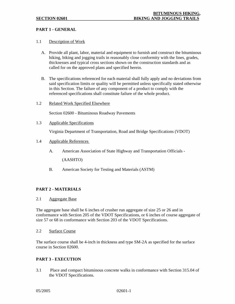
BITUMINOUS HIKING, SECTION 02601 BIKING AND JOGGING TRAILS
05/2005 02601-1
PART 1 - GENERAL
1.1 Description of Work
A. Provide all plant, labor, material and equipment to furnish and construct the bituminous
hiking, biking and jogging trails in reasonably close conformity with the lines, grades, thicknesses and typical cross sections shown on the construction standards and as called for on the approved plans and specified herein.
B. The specifications referenced for each material shall fully apply and no deviations from
said specification limits or quality will be permitted unless specifically stated otherwise in this Section. The failure of any component of a product to comply with the referenced specifications shall constitute failure of the whole product.
1.2 Related Work Specified Elsewhere
Section 02600 - Bituminous Roadway Pavements
1.3 Applicable Specifications
Virginia Department of Transportation, Road and Bridge Specifications (VDOT)
1.4 Applicable References
A. American Association of State Highway and Transportation Officials -
(AASHTO)
B. American Society for Testing and Materials (ASTM)
PART 2 - MATERIALS
2.1 Aggregate Base
The aggregate base shall be 6 inches of crusher run aggregate of size 25 or 26 and in conformance with Section 205 of the VDOT Specifications, or 6 inches of course aggregate of size 57 or 68 in conformance with Section 203 of the VDOT Specifications.
2.2 Surface Course
The surface course shall be 4-inch in thickness and type SM-2A as specified for the surface course in Section 02600.
PART 3 - EXECUTION
3.1 Place and compact bituminous concrete walks in conformance with Section 315.04 of
the VDOT Specifications.
BITUMINOUS HIKING, SECTION 02601 BIKING AND JOGGING TRAILS
05/2005 02601-2
PART 4 - MEASUREMENT AND PAVEMENT
4.1 Bituminous concrete pavement shall be based on 120 pounds per sq. yd. per inch of depth and shall be measured to the width shown on the approved plans regardless of the actual dimension constructed. Payment shall be in tons of bituminous concrete installed.
4.2 Aggregate base shall be measured to the width shown on the approved plans regardless
of the actual dimensions constructed. Payment shall be in cubic yards of material installed.
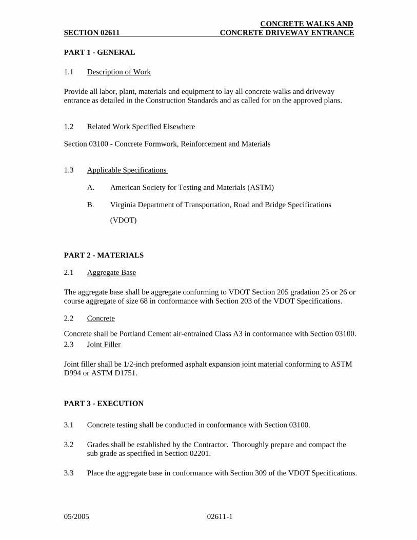
CONCRETE WALKS AND SECTION 02611 CONCRETE DRIVEWAY ENTRANCE
05/2005 02611-1
PART 1 - GENERAL
1.1 Description of Work
Provide all labor, plant, materials and equipment to lay all concrete walks and driveway entrance as detailed in the Construction Standards and as called for on the approved plans.
1.2 Related Work Specified Elsewhere
Section 03100 - Concrete Formwork, Reinforcement and Materials
1.3 Applicable Specifications
A. American Society for Testing and Materials (ASTM)
B. Virginia Department of Transportation, Road and Bridge Specifications
(VDOT)
PART 2 - MATERIALS
2.1 Aggregate Base
The aggregate base shall be aggregate conforming to VDOT Section 205 gradation 25 or 26 or course aggregate of size 68 in conformance with Section 203 of the VDOT Specifications.
2.2 Concrete
Concrete shall be Portland Cement air-entrained Class A3 in conformance with Section 03100.
2.3 Joint Filler
Joint filler shall be 1/2-inch preformed asphalt expansion joint material conforming to ASTM D994 or ASTM D1751.
PART 3 - EXECUTION
3.1 Concrete testing shall be conducted in conformance with Section 03100.
3.2 Grades shall be established by the Contractor. Thoroughly prepare and compact the
sub grade as specified in Section 02201.
3.3 Place the aggregate base in conformance with Section 309 of the VDOT Specifications.
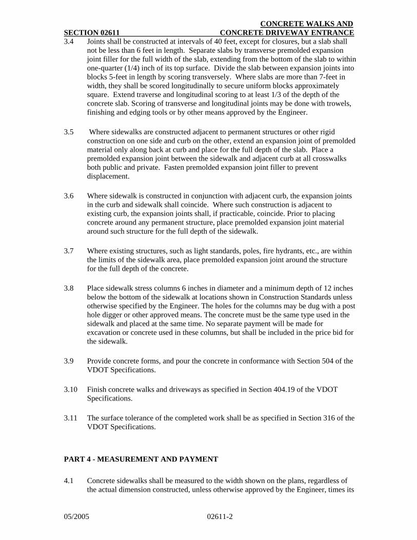
CONCRETE WALKS AND SECTION 02611 CONCRETE DRIVEWAY ENTRANCE
05/2005 02611-2
3.4 Joints shall be constructed at intervals of 40 feet, except for closures, but a slab shall not be less than 6 feet in length. Separate slabs by transverse premolded expansion joint filler for the full width of the slab, extending from the bottom of the slab to within one-quarter (1/4) inch of its top surface. Divide the slab between expansion joints into blocks 5-feet in length by scoring transversely. Where slabs are more than 7-feet in width, they shall be scored longitudinally to secure uniform blocks approximately square. Extend traverse and longitudinal scoring to at least 1/3 of the depth of the concrete slab. Scoring of transverse and longitudinal joints may be done with trowels, finishing and edging tools or by other means approved by the Engineer.
3.5 Where sidewalks are constructed adjacent to permanent structures or other rigid
construction on one side and curb on the other, extend an expansion joint of premolded material only along back at curb and place for the full depth of the slab. Place a premolded expansion joint between the sidewalk and adjacent curb at all crosswalks both public and private. Fasten premolded expansion joint filler to prevent displacement.
3.6 Where sidewalk is constructed in conjunction with adjacent curb, the expansion joints
in the curb and sidewalk shall coincide. Where such construction is adjacent to existing curb, the expansion joints shall, if practicable, coincide. Prior to placing concrete around any permanent structure, place premolded expansion joint material around such structure for the full depth of the sidewalk.
3.7 Where existing structures, such as light standards, poles, fire hydrants, etc., are within
the limits of the sidewalk area, place premolded expansion joint around the structure for the full depth of the concrete.
3.8 Place sidewalk stress columns 6 inches in diameter and a minimum depth of 12 inches
below the bottom of the sidewalk at locations shown in Construction Standards unless otherwise specified by the Engineer. The holes for the columns may be dug with a post hole digger or other approved means. The concrete must be the same type used in the sidewalk and placed at the same time. No separate payment will be made for excavation or concrete used in these columns, but shall be included in the price bid for the sidewalk.
3.9 Provide concrete forms, and pour the concrete in conformance with Section 504 of the
VDOT Specifications.
3.10 Finish concrete walks and driveways as specified in Section 404.19 of the VDOT
Specifications.
3.11 The surface tolerance of the completed work shall be as specified in Section 316 of the
VDOT Specifications.
PART 4 - MEASUREMENT AND PAYMENT
4.1 Concrete sidewalks shall be measured to the width shown on the plans, regardless of the actual dimension constructed, unless otherwise approved by the Engineer, times its
CONCRETE WALKS AND SECTION 02611 CONCRETE DRIVEWAY ENTRANCE
05/2005 02611-3
actual length. Payment shall be in square yards for each type of concrete walk, and shall include the cost of stress columns.
4.2 Concrete driveway entrances shall be measured by the square yard of driveway entrance placed to the limits shown on approved drawings and indicated by the Engineer. Payment shall be in square yards for each type of driveway entrance.
4.3 Aggregate base shall be measured to the width and depth shown on the approved plans regardless of the actual dimensions constructed, unless otherwise approved by the Engineer. Payment shall be in cubic yards of material constructed.
4.4 Excavation shall be measured in cubic yards in its original condition based on the cut
sheets and typical section. Payment shall be in cubic yards as described in Section 02201.

SECTION 02612 INTERLOCKING CONCRETE AND BRICK PAVERS
05/2005 02612-1
PART 1 - GENERAL
1.1 Description of Work
Provide all labor, plant, material and equipment to lay interlocking concrete or brick pavers to line and grade as detailed in the Construction Standards and as called for on the approved plans.
1.2 Relate Work Specified Elsewhere
Section 02611 - Concrete Walks and Concrete Driveway Entrances
Section 02613 - Paver Crosswalk
Section 03100 - Concrete Formwork, Reinforcement and Materials
Section 04100 - Mortar and Grout
1.3 Applicable Specifications
A. American Association of State Highways and Transportation Officials
(AASHTO)
B. American Society for Testing and Materials (ASTM)
C. Virginia Department of Transportation, Road and Bridge Specifications (VDOT)
D. Concrete Paver Institute (CPI), a division of the National Concrete Masonry Association (NCMA)
1.4 Quality Assurance
A. Installation shall be performed by an installer with at least one year experience
in placing interlocking concrete and brick pavers.
1.5 Submittals
A. Submit shop or product drawings and product data.
B. Submit samples of paver units to indicate color and shape selection.
C. Submit sieve analysis for grading of bedding and joint sand.
D. Submit test results for compliance of paver unit requirements to ASTM C936 from an independent testing laboratory.
1.6 Environmental Conditions
A. Do not install sand or pavers during rain or snowfall.
B. Do not use frozen sand.
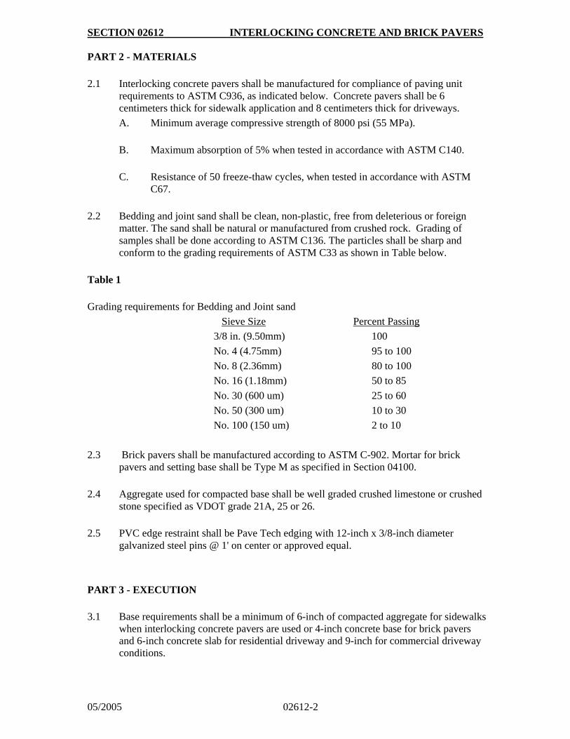
SECTION 02612 INTERLOCKING CONCRETE AND BRICK PAVERS
05/2005 02612-2
PART 2 - MATERIALS
2.1 Interlocking concrete pavers shall be manufactured for compliance of paving unit
requirements to ASTM C936, as indicated below. Concrete pavers shall be 6 centimeters thick for sidewalk application and 8 centimeters thick for driveways.
A. Minimum average compressive strength of 8000 psi (55 MPa).
B. Maximum absorption of 5% when tested in accordance with ASTM C140.
C. Resistance of 50 freeze-thaw cycles, when tested in accordance with ASTM
C67.
2.2 Bedding and joint sand shall be clean, non-plastic, free from deleterious or foreign
matter. The sand shall be natural or manufactured from crushed rock. Grading of samples shall be done according to ASTM C136. The particles shall be sharp and conform to the grading requirements of ASTM C33 as shown in Table below.
Table 1
Grading requirements for Bedding and Joint sand
Sieve Size Percent Passing
3/8 in. (9.50mm) 100
No. 4 (4.75mm) 95 to 100
No. 8 (2.36mm) 80 to 100
No. 16 (1.18mm) 50 to 85
No. 30 (600 um) 25 to 60
No. 50 (300 um) 10 to 30
No. 100 (150 um) 2 to 10
2.3 Brick pavers shall be manufactured according to ASTM C-902. Mortar for brick pavers and setting base shall be Type M as specified in Section 04100.
2.4 Aggregate used for compacted base shall be well graded crushed limestone or crushed
stone specified as VDOT grade 21A, 25 or 26.
2.5 PVC edge restraint shall be Pave Tech edging with 12-inch x 3/8-inch diameter
galvanized steel pins @ 1' on center or approved equal.
PART 3 - EXECUTION 3.1 Base requirements shall be a minimum of 6-inch of compacted aggregate for sidewalks
when interlocking concrete pavers are used or 4-inch concrete base for brick pavers and 6-inch concrete slab for residential driveway and 9-inch for commercial driveway conditions.
SECTION 02612 INTERLOCKING CONCRETE AND BRICK PAVERS
05/2005 02612-3
3.2 Aggregate base materials shall be compacted to a density of 95 percent of Modified Proctor ensity with a tolerance of +1/4-inch to the following grades.
6 cm concrete pavers - 3 1/2-inch below finish grade of pavers
8 cm concrete pavers - 4 1/4-inch below finish grade of pavers
brick pavers - N/A
3.3 The sand leveling course for concrete pavers shall be screeded loose to a thickness of 1-inch to 1-1/2-inch. The exact thickness shall be determined at the job site. Care shall be taken to ensure the leveling base is loose and is not disturbed.
3.4 The leveling base shall be treated with a soil stabilizer to prohibit the growth of grass.
3.5 The concrete pavers shall be installed hand tight being careful not to disturb the laying
bed. The use of string line may be required to keep straight lines. A motor-driven masonry saw shall be used to cut edges where straight pavers can not be used. Hammer cutting is not acceptable. No cut segment shall be smaller than one third of a paver unit measured in any direction.
3.6 Concrete pavers shall then be vibrated into leveling base with a vibratory plate capable
of 3,500 to 5,000 pound compaction force. This must be done prior to any rain.
3.7 Joints shall be filled after vibration using dry sand. Brush and vibrate sand into joints
until they are completely filled, then remove surplus sand.
3.8 All work to within three feet of the laying face must be left fully compacted with sand-
filled joints at the completion of each day. Cover the remaining uncompacted edge of the laying face and sand with waterproof covering.
3.9 Brick pavers shall be laid into a mortar setting bed and leveled. All joints shall be
filled completely with mortar.
3.10 The color of the concrete or brick pavers shall be as indicated on approved plans.
Pavers shall be selected from four or more cubes to blend color and texture variations. The laying pattern shall be herringbone unless specified otherwise.
3.11 Do not finish concrete base as provided for in Section 02611.
3.12 Edge restraints shall be 1/4-inch below the top of the edge pavers to minimize the
potential for tripping and to allow for minor settlement of the pavers and to assure drainage of pavement runoff.
3.13 The final surface elevations shall not deviate more than 3/8-inch under a 10 foot long
straight edge.
3.14 The surface elevation of pavers shall be 1/8 to 1/4 inch above adjacent drainage inlets,
concrete collars or channels.
SECTION 02612 INTERLOCKING CONCRETE AND BRICK PAVERS
05/2005 02612-4
PART 4 - MEASUREMENT AND PAYMENT
4.1 Interlocking concrete and brick pavers for sidewalk application shall be measured to
the width shown on the plans, regardless of the actual dimension constructed, unless otherwise approved by the Engineer, times its actual length. Payment shall be in square yards for each type of masonry walk installed, complete in place and shall include the necessary preparation of the sub grade surface, aggregate base, sand leveling base, filter fabric and edge restraints, if required.
4.2 Excavation shall be measured in cubic yards in its original condition based on the cut sheets and typical sections. Payment shall be in cubic yards as described in Section 02201.
SECTION 02613 PAVER CROSSWALK
05/2005 02613-1
PART 1 - GENERAL
1.1 Description of Work
Provide all labor, materials, equipment and services necessary to complete the crosswalk as shown on the drawings and specified herein.
1.2 Related Work Specified Elsewhere
Section 02611 - Concrete Walks & Concrete Driveway Entrance
Section 02612 - Interlocking Concrete and Brick Pavers
Section 03100 - Concrete, Formwork, Reinforcement and Materials
Section 04100 - Mortar and Grout
1.3 Applicable Specifications
A. American Society for Testing and Materials (ASTM)
B. Virginia Department of Transportation, Road and Bridge Specifications
(VDOT)
C. Concrete Paver Institute (CPI), a division of the National Concrete Masonry
Association (NCMA)
1.4 Submittals
A. Samples: Submit the following samples:
1. Five concrete units of masonry showing full range of color and texture.
B. Certificates of Conformance: Submit certificates from the manufacturer
attesting that the concrete pavers meet the requirements specified.
1. Concrete Pavers
2. Mortar Coloring
3.
1.5 Quality Assurance
A. Handling and Storage
1. Handle, sort, and protect masonry units in a manner to avoid chipping, breakage or contact with the soil. Keep ties, and joint reinforcement free of rust. Steel reinforcing bars shall be free of loose scale and rust. Reject rusted steel reinforcing, ties and joint reinforcement. Deliver cement in unbroken bags, barrels, or other sealed containers, plainly marked and labeled with the manufacturer's names and brands. Store cementitious materials in dry, weather tight sheds or enclosures or under watertight tarpaulins. Sort and handle cement in a manner which will prevent the inclusion of foreign materials and damage by water or dampness.
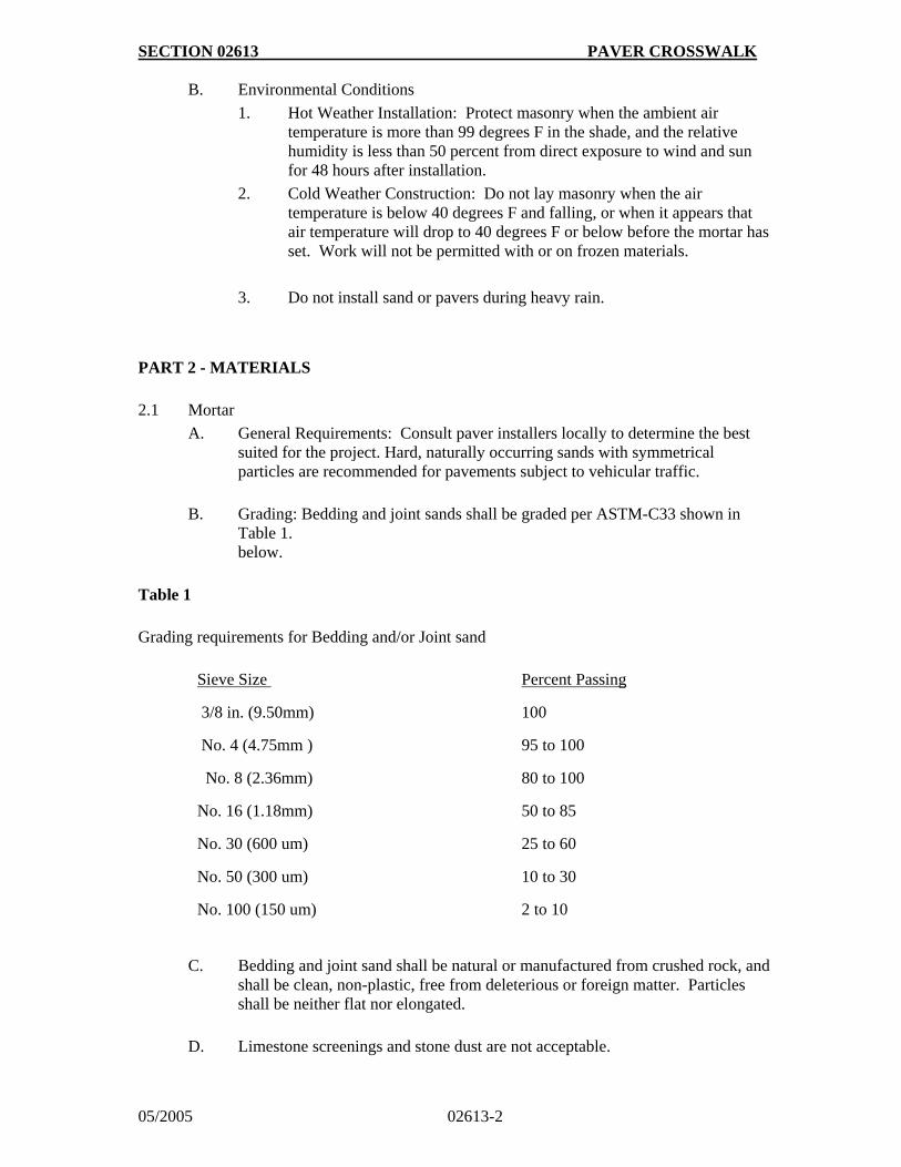
SECTION 02613 PAVER CROSSWALK
05/2005 02613-2
B. Environmental Conditions
1. Hot Weather Installation: Protect masonry when the ambient air temperature is more than 99 degrees F in the shade, and the relative humidity is less than 50 percent from direct exposure to wind and sun for 48 hours after installation.
2. Cold Weather Construction: Do not lay masonry when the air temperature is below 40 degrees F and falling, or when it appears that air temperature will drop to 40 degrees F or below before the mortar has set. Work will not be permitted with or on frozen materials.
3. Do not install sand or pavers during heavy rain.
PART 2 - MATERIALS
2.1 Mortar
A. General Requirements: Consult paver installers locally to determine the best suited for the project. Hard, naturally occurring sands with symmetrical particles are recommended for pavements subject to vehicular traffic.
B. Grading: Bedding and joint sands shall be graded per ASTM-C33 shown in
Table 1. below.
Table 1
Grading requirements for Bedding and/or Joint sand
Sieve Size
3/8 in. (9.50mm)
No. 4 (4.75mm )
No. 8 (2.36mm)
Percent Passing
100
95 to 100
80 to 100
No. 16 (1.18mm)
No. 30 (600 um)
No. 50 (300 um)
No. 100 (150 um)
50 to 85
25 to 60
10 to 30
2 to 10
C. Bedding and joint sand shall be natural or manufactured from crushed rock, and shall be clean, non-plastic, free from deleterious or foreign matter. Particles shall be neither flat nor elongated.
D. Limestone screenings and stone dust are not acceptable.
SECTION 02613 PAVER CROSSWALK
05/2005 02613-3
E. Sieve analysis on samples shall be graded per ASTI-C236.
2.2 Concrete Pavers
Concrete pavers shall be 8 centimeters thick for crosswalk application and shall be as specified in Section 02612. The color and laying pattern shall match the adjacent sidewalk as indicated on the drawings.
2.3 Concrete Base Slab
The concrete base slab, slab reinforcing and expansion joints shall be as specified in Section 03100 of these specifications.
2.4 Aggregate Subbase
The aggregate subbase shall be gradation 21A conforming to VDOT Specifications, Section
208.
2.5 Geotextile
Shall be woven of polyester or polypropylene fibers, with a permeability rating 10 times greater than that of soil on which paving is founded and an apparent opening size (AOS), small enough to prevent passage of fines from setting bed into soil sub grade or graded aggregate base.
PART 3 - EXECUTION
3.1 Examine the areas and conditions where masonry is to be installed and notify the
Engineer of conditions detrimental to the proper and timely completion of the work. Do not proceed with the work until unsatisfactory conditions have been corrected by the Contractor in a manner acceptable to the Engineer.
3.2 Lay the aggregate subbase to the compacted thickness shown on the drawings and in
conformance with Section 308 of the VDOT Specifications.
3.3 The concrete base slab shall be installed in accordance with the drawings, details and
Section 03100 of these specifications.
3.4 All paving adjoining the crosswalk shall be complete before the sand setting bed is
laid. This includes all patching of existing adjoining pavement. Steel rollers used to compact the pavement shall not run over the pavers.
3.5 All pavers shall be free of foreign materials before installation. Do not use concrete
pavers with excessive chips, cracks, voids stains or other defects that might be visible in the finished work. allowed on the bottom of the pavers.
SECTION 02613 PAVER CROSSWALK
05/2005 02613-4
3.6 The base concrete slab shall be cleaned of all asphaltic concrete components, dust, oil, or any other material. The finished surface of the base to receive the bedding sand shall be uniform and even, and shall not deviate by more than +0 and -1/2 inch (13mm) over 10' (3m) when measured in any direction.
3.7 Place sand for setting bed and screed to thickness of 1 inch to 1 1/2 inch (25 to 40 mm), taking care that moisture content remains constant and the density if loose and constant until all pavers are set and compacted.
3.8 Lay setting bed so that elevation of top surface of pavers shall be 1/8 inch (3mm) min to
1/4 inch (6mm) max. above adjacent drainage inlets, concrete collars, channels, or other pavements after compaction.
3.9 Lay unit pavers in joint pattern shown on the drawings.
3.10 Set concrete pavers with a minimum joint width of 1/16 inch (1.5mm) and a maximum
of 3/16 inch (5mm), being careful no to disturb leveling base. If pavers have spacer bars, place pavers hand tight against spacer bars. Concrete pavers with spacer bars on sides of each unit are recommended when installation is performed with mechanical equipment. Use string lines to deep straight lines. Select units from 4 or more cubes to blend color and texture variations. Fill gaps at edge restraints that exceed 3/8 inch (10mm) with pieces cut to fit from full size unit pavers.
3.11 Vibrate concrete parers into leveling course with a low amplitude plate vibrator capable
of a 3,000 to 5,000 pound (13 to 22 KN) compaction force.
3.12 Vibrate after edge pavers are installed, and there is a completed, restrained surface: or
before surface is exposed to rain. Vibrate installed concrete pavers within 3 feet (1m) of the laying face and cover with sand BEFORE ENDING EACH DAY'S WORK.
3.13 Spread dry sand and fill joints immediately after vibrating pavers into leveling course.
Brush and vibrate sand into joints until they are completely filled, then remove surplus sand.
3.14 Do not allow traffic on installed concrete pacers until sand has been vibrated into
joints.
3.15 Final surface elevations shall not deviate more than 3/8 inch (10 mm) under a 10 foot
(3m) long straightedge.
PART 4 - MEASUREMENT AND PAYMENT
Paver crosswalks shall be measured to the width shown on the plans, regardless of the actual dimension constructed times its actual length. Payment shall be in square yards for the type paver crosswalk installed, including the necessary preparation of sub grade, restoration of adjacent pavement, excavation, aggregate subbase, concrete base and incidentals necessary for a complete installation.
SECTION 02650 RESTORATION OF ROADWAY
05/2005 02650-1
PART 1 - GENERAL
1.1 Description of Work
Provide the necessary plant, labor, materials and equipment to restore and maintain the various street and driveway surfaces of all types, pavement and driveway bases, curbs, curb and gutter, and sidewalks disturbed, damaged or demolished during the performance of the work.
1.2 Related Work Specified Elsewhere
Section 02600 - Bituminous Roadway Pavements
Section 02601 - Bituminous Hiking, Biking and Jogging Trails
Section 02611 - Concrete Walks and Concrete Driveway Entrance
Section 02612 - Interlocking Concrete and Brick Pavers
Section 02750 - Curb and Gutters
Section 03100 - Concrete Formwork, Reinforcement and Materials
1.2 Applicable Specifications
A. American Society for Testing and Materials (ASTM)
B. Virginia Department of Transportation, Road and Bridge Specifications (VDOT)
1.4 Applicable Reference
American Association of State Highway and Transportation Officials (AASHTO)
1.5 Permits
Before performing any work, secure the necessary permits to work within the County or State right of way and easements when surface materials will be disturbed or demolished.
PART 2 - MATERIALS
2.1 The quality of materials used in the restoration of existing pavements and driveways
shall produce a street surface equal to or better than the condition before the work began.
2.2 Concrete shall be Class A3 air-entrained Portland cement type as specified in Section 03100.
2.3 The base and surface courses shall be BM-2 and SM-2A respectively as specified in
Section 02600.
SECTION 02650 RESTORATION OF ROADWAY
05/2005 02650-2
2.4 Crusher run aggregate shall be size 25 in conformance with Section 206 of the VDOT Specifications.
2.5 Joint filler shall be 1/2-inch preformed asphalt expansion joint material conforming at
ASTM 1751.
2.6 Asphalt for a temporary patch shall be BM-2 as specified in Section 02600.
PART 3 - EXECUTION
3.1 Where trenches have been opened in any roadway or street that is a part of the State of
Virginia highway system, restore surfaces in accordance with the requirements of VDOT. All other restoration shall be done in accordance with the Contract Drawings, these specifications, and the Construction Standards.
3.2 Excavation in the pavement area shall require that pavement surfaces be saw-cut to
provide a straight and smooth edge. Cut out pavement 24-inches wider than the trench width or excavation opening as shown on Construction Standard M-6.0.
3.3 Upon completion of installation of utility and backfill, fill the top 18-inches of the
trench with crusher run and temporary asphalt patch until such time that the permanent pavement patch will be constructed.
3.4 Complete the pavement restoration for the various types of streets in conformance with
Construction Standard M-6.0 and Section 02600.
3.5 Concrete curb and gutter, and sidewalks, shall be restored as required to match existing
construction. Replace damaged sections with complete new sections or squares; patching of damaged sections will not be permitted.
3.6 Maintain restored sections and surfaces as part of the Contract requirements for a
period of one year following the date of final acceptance.
3.7 When a manhole top requires adjustment to an elevation one inch or more above the
existing pavement grade and is exposed to traffic before final paving is completed, a temporary ramp shall be constructed by feathering bituminous concrete for 360 degrees around the manhole.
A taper slope of not less than two feet per one inch shall be used. During the paving operation but prior to the placement of the topping course the bituminous concrete taper shall be removed from around the manhole to a minimum depth of one inch below the top of manhole.
PART 4 - MEASUREMENT AND PAYMENT
4.1 Pavement restoration shall be measured in square yards of the surface area restored
based on the payment width, regardless of actual dimension constructed times its actual
SECTION 02650 RESTORATION OF ROADWAY
05/2005 02650-3
length. Payment shall be in square yards per category of street pavement restored and shall include the necessary preparation of the sub grade surface, tack coats, bituminous concrete materials, and the crusher run backfill required in paragraph 3.3.
4.2 Concrete curb and gutter shall be measured in linear feet of actual replacement.
Payment shall be in linear feet of curb and gutter at the price bid.
4.3 Concrete sidewalk restoration shall be measured in square yards to restore to original
width. Payment shall be in square yards for each type of concrete walk, plain concrete or concrete with brick, and shall include the cost of stress columns.
4.4 There shall be no payment for temporary asphalt patch.

SECTION 02750 CURB AND GUTTERS
05/2005 02750-1
PART 1 - GENERAL
1.1 Description of Work
Provide all plant, labor, materials and equipment to install the concrete curbs and combination concrete curb and gutters as called for on the approved plans, as detailed on the Construction Standards, and as specified herein.
1.2 Related Work Specified Elsewhere
Section 02611 - Concrete Walks and Concrete Driveway Entrance
Section 03100 - Concrete Formwork, Reinforcement and Materials
1.3 Applicable Specification
A. American Association of State Highway and Transportation Officials (AASHTO)
B. American Society for Testing and Materials (ASTM)
C. Virginia Department of Transportation, Road and Bridge Specifications
(VDOT)
PART 2 - MATERIALS
2.1 Concrete
Concrete shall be Portland cement class A3 in conformance with Section 03100.
2.2 Joint Filler
Joint filler shall be 1/2-inch performed asphalt expansion joint material conforming to ASTM D994 or ASTM D1751.
2.3 Subbase
The subbase materials shall be in conformance with VDOT Section 208, gradation size 21A.
PART 3 - EXCAVATION 3.1 Construct the sub grade to the required elevation below the finished surface of the
gutter in accordance with dimensions and design as shown on Construction Standards. Remove all soft and unsuitable material and replace with subbase material, which shall be compacted to 95% density in accordance with AASHTO T-99 and finished to a smooth surface. Moisten the subbase prior to placing the concrete.
3.2 Construct forms of wood or metal conforming to VDOT Section 403.03.
SECTION 02750 CURB AND GUTTERS
05/2005 02750-2
3.3 Prior to placing concrete, check the line and grade for accuracy and fasten the face
forms of the curb to the gutter forms. Spade the concrete and tamp sufficiently to bring the mortar to the surface, after which finish with a magnesium float. Construction shall be in sections of uniform lengths, providing transverse joints at approximately 10-feet intervals and when the time elapsing between placements exceeds 45 minutes. No section shall be less than 6 feet in length. Separate sections by plate steel templates set perpendicular to the grade and center line of the unit specified. The templates shall be 1/8-inch in thickness and shall have a width and depth equal to the unit cross-section. Leave these templates in place until the concrete has set sufficiently to hold its shape.
3.4 Form expansion joints at intervals of 100 feet or less. When the curb and gutter is
constructed adjacent to rigid pavements, the location and width of expansion joints shall coincide with those in the pavement, where practicable. Where stationary structures, such as catch basins and drop inlets, are within the limits of the curb and gutter, place an expansion joint between the structure and the curb and gutter. Place expansion joints at all returns.
3.5 Screed the face and top of curb and surface of gutter smooth and round the edges to a
radius as shown on the Construction Standards.
3.6 As soon as the concrete has attained sufficient set, remove the face forms of the curb.
The exposed surfaces shall be screeded with a straight edge and finished with a steel trowel. Remove all trowel marks with a brush wet with clear water. Do not use mortar in finishing.
3.7 The finished surface of curb and gutter shall be true to line and grade with an allowable
tolerance as specified in Section 316.05 of the VDOT Specifications.
3.8 After the concrete has set in conformance with Section 03100, fill the spaces on both
sides of gutter or the back side of curb to the required elevation with suitable material and compact to 95 percent density in accordance with AASHTO T-99 in layers of not more than 6-inches.
PART 4 - MEASUREMENT AND PAYMENT
4.1 Measurement shall be in linear feet of actual construction. Payment will be at the unit
price bid per type of curb section bid, except where the curb or curb and gutter is adjacent to catch basins or drop inlets, in which case the unit price for such catch basins or drop inlets shall include that part of the curb and gutter within the limits of the structure.
4.2 Subbase material shall be measured to the width and depth shown on the approved
plans regardless of the actual dimensions constructed. Payment shall be in cubic yards of material installed.
SECTION 02800 LANDSCAPING
05/2005 02800-1
PART 1 - GENERAL
1.1 Description of Work
Provide all plant, materials and labor required to execute this work as indicated on the approved plans, as specified and as necessary to complete the Contract, including, but not limited to, soil treatment; planting of trees, topsoil in planting areas; protection, maintenance, warranty, and replacement of plants; related items of work as indicated on drawings; inspection; and maintenance.
1.2 Related Work Specified Elsewhere
Section 02100 - Clearing and Grubbing
Section 02200 - Earthwork for Structures and Pipelines
Section 02801 - Seeding and Sodding
1.3 Applicable References
A. Arlington County Cooperative Extension Office
B. Erosion and Sediment Control Ordinance (Chapter 57 of the Arlington County Code)
C. Hortus III, 1979 Edition
D. American Association of Nurseryman's Standards
E. Maryland Forest Conservation Manual
1.4 Permits
Before any tree may be planted on public rights-of-way, or County easements, a permit from the Department of Environmental Services shall be obtained, and reviewed and approved by PRCR.
1.5 Plant Warranty and Replacement
A. Warranty: Guarantee that plants will be alive and in satisfactory growth for a
period of two years, beginning the day the County has approved the planting.
B. Replace dead or dying plants as soon as possible at no cost to the County.
C. Plants used for replacement shall be the same species and size as specified in
Plant List; plant, mulch, maintain and warrant as specified.
D. Properly maintain all planting and planting areas during the progress of the
work and for a maintenance period of 60 days after acceptance.
SECTION 02800 LANDSCAPING
05/2005 02800-2
PART 2 - MATERIALS
2.1 Shrubs and Trees
A. Shrubs and trees shall be of a variety, size and quantity as shown on the
approved plans and shall be planted where shown on the planting plan. Plants shall be symmetrical, typical for variety and species, sound, vigorous, free from plant disease, insect pests or their eggs, and shall have healthy, normal root systems, well filling their containers, but not to the point of being root-bound. Plants not conforming to these requirements shall be considered defective, and shall be removed from the site immediately, and replaced with approved stock at the Contractor's expense.
2.2 Water
Water shall be provided by the Contractor for use of this trade.
2.3 Miscellaneous
Mulch: Shredded hardwood.
Soil: Natural for the area, fertile, friable and within acceptable pH limits for
the shrubs and trees.
Fertilizer: Of the type and composition recommended by the Arlington County Cooperative Extension Office, 855 North Edison Street, Arlington, Virginia.
Tree Stakes: 2-inch x 2-inch x 8-inch hardwood pointed on one end.
Tree Grates: 180o square, flush, non-bolt, equal of Neenah Type R-8640.
PART 3 - EXECUTION
3.1 Delivery, Storage, and Soil Testing
Contact the Arlington County Cooperative Extension Office for soil testing. Deliver plants to the site in a healthy condition and properly store and protect for planting.
3.2 Grading
A. Do not plant until finish grades are established and planting areas are properly
prepared and graded.
B. Do not work the soil when the moisture content is so great that excessive
compaction will occur; nor when it is so dry a dust will form in the air or that clods will not break readily.
SECTION 02800 LANDSCAPING
05/2005 02800-3
Apply water, if necessary, to provide ideal moisture for filling and for planting
as herein specified.
C. Preliminary grading shall be done in such a manner as to anticipate the finish
grading. Remove excess soil or redistribute before application of fertilizer and mulch. Where soil is to be replaced by plants and mulch, make allowances so that, when finish grading has begun, there shall be no deficiency in the specified depth of mulched planting beds.
D. When preliminary grading, including weeding and fertilizing, has been completed and the soil may be readily worked, grade all planting areas to a smooth, even and uniform plane with no abrupt change of surface. Slope soil areas adjacent to buildings away from the buildings, and direct surface drainage as indicated on the drawings.
3.2 Planting of Shrubs and/or Trees
A. Remove canned stock by cutting can vertically on two opposite sides of can
with instrument approved for the purpose.
B. Spacing: Where plant material is shown on the drawings in a –“loose” pattern,
space the material as shown, at all times maintaining an unequal, random spacing and conforming to the Tree Planting Details of the Construction Standards.
C. Dig tree pits and plant pits in accordance with the Tree Planting Details,
Drawing Nos. R-7.1, R-7.2 and R-7.6 of these Construction Standards.
D. Setting: Plants shall bear some relation to soil level when planted as they did
when in container. Place each plant in center of plant pit.
E. Cut burlap, twine and wire baskets from top 12 inches of rootball and remove
from site.
1. Backfill with 1/2 clean existing soil, 1/4 sand, 1/4 peat moss.
F. Firmly tamp backfill material into plant pits around and under the root ball to
force out all air pockets. Backfill in conformance with the Tree Planting Details of the Construction Standards.
G. Basin each plant with a berm 3 inches in height above crown of root ball
immediately after planting and thoroughly water to saturate the root ball and backfill.
H. Stake all trees with hardwood stakes driven 2' into firm ground and secure tree
to stake as per detail R-7.2 (Planting and Guying For Trees Over 2 1/2-inch Caliper).
SECTION 02800 LANDSCAPING
05/2005 02800-4
PART 4 - MEASUREMENT AND PAYMENT
4.1 Shrubs and trees shall be measured as each, by variety and size. Payment shall include
the labor, materials and equipment necessary for a proper and complete installation, but shall not include tree grates.
4.2 Tree grates shall be measured as each, by size. Payment shall include the labor,
materials and equipment necessary for a complete installation.
SECTION 02950 SEEDING AND SODDING
05/2005 02801-1
PART 1 - GENERAL
1.1 Description of Work
Provide all labor, materials, tools and equipment as required to have topsoil, fertilizer, lime, mulch, seed and/or sod applied on all areas disturbed by construction and all areas called for on the approved plans.
1.2 Related Work Specified Elsewhere
Section 02100 - Clearing and Grubbing
Section 02200 - Earthwork for Structures and Pipelines
1.3 Applicable Specifications Virginia Field Seed Law
1.3 Applicable Reference
Erosion and Sediment Control Ordinance (Chapter 57 of the Arlington County Code)
Virginia Tech Specification
1.5 Submittals
In accordance with Section 01300 submit proposed names of fertilizers, sod and seed mixtures together with their composition and any certificates requested to the Engineer for approval.
1.6 Quality Assurance
The results of testing two samples from each source of topsoil to ensure that proper types and quantities of soil conditioners, and fertilizers, will be used resulting in a dense, vigorous growth of perennial lawn-quality grass. The results of this test will determine rates and types of fertilizers and lime. For seeding, the Virginia Tech rates for seeding shall be used as specified by VA/MD seed/ sod program, if available.
1.7 Testing
Test seed within 6 months of seeding to meet the requirements of the Virginia Field Seed Law for percentage of germination as follows:
Kentucky 31:
German Foxtail Millet:
Abruzzi Tye:
Red Top:
81%
78%
78%
77%
SECTION 02950 SEEDING AND SODDING
05/2005 02801-2
PART 2 - MATERIALS
2.1 Topsoil
A. Topsoil shall be a natural, fertile, friable soil, typical of productive soil in the
vicinity, obtained from naturally well drained areas, neither excessively acid nor alkaline, and containing no substances harmful to grass growth.
2.2 Fertilizer
A. As per Virginia Tech Specifications, soil test will be taken and fertilizer will be
applied for seeding areas disturbed by clearing operations.
2.3 Seed
A. For seeding areas disturbed by clearing operations only; where vegetation remains:
Per acre: March to July: Tall fescue, per current year
Virginia Tech Recommended List
50 pounds
German Foxtail Millet:
30 pounds
August to February: Tall fescue, per current year Virginia Tech Recommended List
Abruzzi Rye:
20 pounds
B. For all other areas:
Per acre: Tall fescue, per current year Virginia Tech Recommended List
70 pounds Red Top: 3 Pounds
Under all conditions, seed shall be of the latest seed crop available.
2.4 Lime
Per acre: 2 tons/ground limestone of such fitness that 50% will pass through a U.S. Standard No. 100 mesh screen and 100% will pass through a U.S. Standard No. 10 mesh screen.
2.5 Mulch
SECTION 02950 SEEDING AND SODDING
05/2005 02801-3
Per acre: 2 tons of small grain mulch of high quality showing no rotting or caking and reasonably free of weeds.
2.6 Sod
Sod shall be vigorous, well-rooted, healthy turf, free from disease, insect pests, weeds, other grass, stones and of similar mix as used in seeding lawns. It shall be suitable character for the purpose intended and for the soil in which it is to be planted. Sod shall be certified at least eight (8) inches wide, not less than twelve (12) inches long, and shall have at least one and one half (1-1/2) inches in thickness, of dirt on its roots. Do not use broken or damaged sod.
2.7 Jute or Fabric
A. Jute matting shall be of a uniform open plain weave of undyed and unbleached
single juteyarn of a width of 4 feet. All material shall be new. Staples shall be made from No. 8gauge or heavier steel wire and bent to form a –“U” with a staple 1 to 1- 1/2 inches wide with 6 inch feet.
B. Fabric shall be a combination of paper and yarn manufactured into plastic
netting interwoven with paper strips as manufactured by Hold/Gro, Gulf States Paper Corporation. Staples shall be 6 inches high carbon iron.
PART 3 - EXECUTION 3.1 Topsoil
A. After approval of rough grading rototill all areas indicated on the drawings and
on other areas damaged by construction, as specified by PRCR, to a depth of 4-inch, removing stumps, all foreign objects and stones larger than one inch diameter; place topsoil approved by PRCR on all areas and incorporate by rototilling into subsoil. Topsoil origin to be specified and approved by PRCR; Certified soil tests specifying pit, % organic matter, textural analysis and N-P-K levels to be made by contractor and approved by PRCR before delivery.
B. Remove stripped topsoil not used at the job site and dispose in a location
approved by the Engineer.
3.2 Fertilizing and Rolling
If required by results of soil tests, Spread soil conditioners and fertilizers and thoroughly incorporate by rototilling work into topsoil to a depth of 4 inches. Rake topsoil until the surface is finely pulverixed and smooth. Compact with rollers weighing not over 100 pounds per linear foot of tread, to an even surface conforming to the prescribed lines and grades. Minimum depth shall be 3 inches after compaction.
3.3 Seeding
SECTION 02950 SEEDING AND SODDING
05/2005 02801-4
A. Seed only when weather conditions are suitable between April 1 and May 30, or August 15 to October 1, unless approved by the Engineer. Use only certified seed blending Kentucky bluegrass cultivars with perennial ryegrass varieties approved by PRCR.
B. If there is a delay in seeding, during which weeds grow or soil is washed out, remove the weeds or replace the soil before sowing the seed, without additional compensation. Immediately before seeding is begun, lightly rake the soil.
C. If required by soil test results, uniformly apply lime, urea form and triple super
phosphate or organic fertilizer approved by (DPRCR), with broadcast spreaders prior to seedbed preparation.
D. Sow seed with mechanical spreaders at the specified rate on a calm day. Sow
one-half the seed in one direction and the other half at right angles. Seed shall be raked lightly into the soil to a depth of 1/4-inch and rolled with a roller weighing not more than 100 pounds per linear foot of tread.
E. If seeding by hydroseeder, add 500 pounds of wood cellulose fiber per acre and
mix with the seed and the 10-10-10 fertilizer at the specified rate. Apply all seed mix within 45 minutes after mixing in hydroseeder to prevent fertilizer damage to seed and inoculants.
F. Keep the surface moist by a fine spray until the grass shows uniform
germination over the entire area. Wherever poor germination occurs in areas larger than three (3) square feet, reseed, roll, and water as necessary to obtain proper germination.
3.4 Mulching
Apply mulch immediately after seeding. Loosen baled straw and thoroughly break up before placing. Begin placement of mulch on the windward side and from the toe to slopes. Do not grind, cut or crush mulch into pieces so small as to form a mat. Cutting mulch to aid in distribution may be accomplished, provided that 10 to 25 percent of the seeded area will be exposed.
On slopes 2 to 1 and greater provide jute matting or Hold/Gro stapled 18 inches to 3 feet apart using closer spacing around curves and areas of concentrated storm water runoff.
Install jute strips beginning 12 inches behind the top of slope. Bury the top ends in a slit trench with prior approval by PRCR, urban forester. Trench should be 6 inches deep, and staple to trench bottom. Reinforce slit trench with a new row of staples one foot below trench and space at intervals of 6 to 10 inches. Staple all overlaps and the center of the material at intervals of 18-inch to 3 feet down the slope. After the jute matting is in place, overseed.
Install Hold/Gro with the fabric running vertically from the top of the slope in the direction of anticipated water flow. Do not stretch the material. Staple Hold/Gro in the same manner as specified for the jute.
SECTION 02950 SEEDING AND SODDING
05/2005 02801-5
3.5 Sodding
A. The Contractor may plant ground cover, not requiring mowing, on grades
exceeding a 2 to 1 slope. The contractor may sod all grades not exceeding a 3:1 slope in lieu of jute or Hold/Gro. or equivalent.
B. On sloping areas where erosion may be a problem, sod shall be laid parallel to the contours of the slope with staggered joints and secured by tamping, pegging or other approved method.
C. Plant only certified sod only when the soil is moist and favorable for growth.
Shape the area to be sodded and finish to the lines and grades indicated on the drawings. Loosen the surface prior to placing sod. Keep the grade moist by sprinkling, if necessary, sod on the prepared surface with the edges in close contact. Each piece of sod laid shall be fitted and tamped into place with hand tampers not less than one hundred (100) square inches in area. Apply a sufficient quantity of water to all sod after laying and to prevent the sod from drying out for a period of at least two weeks to ensure growth.
3.6 Inspection
At the beginning of the next planting season after that in which the permanent grass crop is sown, inspect the seeded areas. Promptly reseed any section not showing dense, vigorous growth. Water, weed, cut and otherwise maintain the lawn until the end of that planting season.
PART 4 - MEASUREMENT AND PAYMENT
Seeding and sodding shall be measured in square yards. Payment shall include all labor, materials, and equipment including topsoil, fertilizers, seed or sod, mulch, jute or other synthetic matting and staples necessary to protect against erosion and required for a satisfactory growth of grass or sod.

SECTION 02950 TUNNELING
05/2005 02950-1
PART 1 - General
1.1 Description of the Work
Provide all plant, labor, materials and equipment to install water mains or sewer pipes by tunneling under railroad or highway crossings as called for on the approved plans and as specified herein.
1.2 Related Work Specified Elsewhere
Section 02110 - Demolition
Section 02202 - Rock Excavation
Section 02510 - Sanitary Sewers & Appurtenances
Section 02550 - Water Mains & Appurtenances
Section 03100 - Concrete Formwork, Reinforcement & Materials
Section 04100 - Mortar and Grout
Section 04200 - Masonry Units
1.3 Applicable Specifications
A. American Association of State Highway and Transportation Officials
(AASHTO)
B. American Society of Testing and Materials (ASTM)
C. United State Bureau of Mines
1.4 Applicable References
Erosion and Sediment Control Ordinance (Chapter 57 of the Arlington County Code)
1.5 Permits and Regulations
The County will obtain all permits required except those permits required for blasting as specified in Section 02110. The Contractor shall conform to the regulations set forth by the authorities having jurisdiction over the work performed in the areas of tunnel crossings.
1.6 Submittals
Submit detailed shop drawings which shall include the location of the tunnel pits, soils data, method of excavation and support, method of dewatering, tunnel linings showing thickness, size, shape and method of attachment, and grouting details. Include details on the method of installing the carrier pipe.
SECTION 02950 TUNNELING
05/2005 02950-2
PART 2 - MATERIALS
2.1 Tunnel Liner Plates
The tunnel liner plates shall be fabricated from structural quality, hot-rolled, carbon steel sheets or plates conforming to ASTM A-570, Grade B for sheets, or ASTM A-283, Grade B for plates. Liner plates shall be galvanized to meet the requirements of AASHTO M-167 and shall provide a minimum diameter of 4'-0-inch. Where specified, the tunnel liner plates shall be bituminous coated to meet the requirements of AASHTO M-190.
All tunnel liner plates shall be flanged and punched for bolting on both longitudinal and circumferential joints and shall be fabricated so as to permit erection from the inside.
2.2 Bolts and Nuts
Bolts and nuts shall be quick acting, coarse thread not less than 1/2-inch in diameter for specified plate thicknesses up to and including 0.179 inches and 5/8-inch in diameter for liner plates of greater thicknesses. Bolts and nuts shall conform to ASTM A307 Grade A and shall be galvanized as per ASTM A153.
2.3 Carrier Pipe
Water mains and sewers shall be as specified in Section 02550 and Section 02510 respectively.
2.4 Concrete
Concrete used in tunneling construction shall be as specified in Section 03100.
2.5 Brickwork
Brick and masonry work performed at the ends of the tunnel shall be as specified in Sections 04100 and 04200.
2.6 Forced Grout
Grout that is force injected between tunnel line plates and tunnel wall shall be one part Portland cement (ASTM C150, Type II), and six parts sand (ASTM C33).
2.7 Equipment
A. Tunneling equipment shall be as approved by U.S. Bureau of Mines.
B. The grout pump and injection system shall deliver the grout in a smooth and even flow without surge while developing a uniform pressure of 50 psi at the grout hole connection.
SECTION 02950 TUNNELING
05/2005 02950-3
PART 3 - EXECUTION
3.1 General
A. Maintain free and full use of the surface on private property, streets, roadways and railways, under which tunneling construction takes place. Maintain close observation of surface facilities to detect settlement or displacement. Notify the Engineer immediately if settlement is detected. Take appropriate action to maintain safe conditions and prevent damage.
B. Should the Contractor elect to sink shafts at any point on the tunnel alignment for more efficient construction, he shall obtain permission from the holders of private property or the agencies having jurisdiction over the property, easement, or right-of-way. Remove excavation from such shaft or shafts, as well as all mucking, from the premises to storage dumps acquired by the Contractor at his own cost and expense. Backfill shafts at no expense to the County with materials approved for backfilling by the Engineer. Line shafts with steel liner plate of structural adequacy to withstand all earth pressures. Plates shall form a concentric circle and be bolted in place as the shaft is sunk. Extend the liner plates above the surface 3-/12' for protection of the public. No shaft shall be less than 12' in diameter. Where shafts are at portals, timber sheeting and bracing of structural adequacy may be used as an alternate to steel liner plates if permission is granted by the Engineer in writing.
3.2 Ventilation System
Furnish, install, operate and maintain a temporary ventilation system for the removal of dust in the tunnel shaft according to local and Federal regulations.
3.3 Electric Lights
Provide temporary electric lights to properly and safely illuminate all parts of the tunnel construction area with special illumination provided at the working face. Lighting circuits shall be thoroughly insulated and separated from power circuits, and shall be enclosed in wire cages. Secure all necessary electrical permits for successful completion of this aspect of the work.
3.4 Excavation for Tunnel Liner Plates
On initial set-up, support the tunneling equipment on a concrete cradle poured to permit the proper installation of the tunneling. During forward movement of tunneling operations, provide sufficient support at the tunnel face to ensure that only materials physically displaced by the tunneling equipment are removed.
Excavation for liner plates shall proceed in increments sufficient for the erection of one ring of liners; install liner plates immediately after each increment of excavation. Keep voids behind liner plates to a minimum.
SECTION 02950 TUNNELING
05/2005 02950-4
3.5 Installation of Tunnel Liner Plates
Handle liner plates in such a manner as to prevent bruising, scaling, or any other damage to the linings and coatings.
Ensure that the plate edges are clean and free from material that could interfere with proper bearing during installation.
Assemble liner plates to the lines and grades shown on the Contract Drawings in accordance with the manufacturers recommendations. Retention or replace any bolt that does not meet the requirements.
On 8' centers and in the liner plate at the top of each ring, there shall be a 2-inch standard half pipe coupling welded into a hole in the liner plate and cast iron closure plugs screwed therein. On the completion of each day's work the cast iron plugs shall be removed and the voids between the outside of the liner plate and the earth or rock shall be completely filled by pressure grouting with one part Portland cement and 6 parts mortar sand. The pressure shall be adequate to fill all the voids, but not great enough to bulge the liner plates.
3.6 Installation of Carrier Pipe in Tunnel
The carrier pipe shall be laid to the true line, grade, and elevations called for in the approved plans. Mount pipe on blocks, saddles, or other approved methods to obtain the exact lines and grades. Secure carrier pipe against flotation or vertical movement in accordance with standard details or as otherwise approved by the Engineer. Protect the ends of tunnel against entry of foreign matter and water with brick and masonry construction of 6-inch minimum grout. Provide 2-inch weep hole at each end of tunnel. Grout or provide sand as shown on the Standard Detail M-5.0.
3.7 Rock Excavation
Rock excavation shall be carried out as specified in Section 02202.
PART 4 - MEASUREMENT AND PAYMENT
Measurement shall be in linear feet of the tunnel liner plate invert. Payment shall include the liner plates, sand or grouting, dewatering and carrier pipe installed, complete in place
SECTION 02951 BORING AND JACKING
05/2005 02951-1
PART 1 - GENERAL
1.1 Description of the Work
Provide all plant, labor, materials and equipment to install water mains or sewer pipes by boring and jacking under highway crossings as called for on the approved plans and as specified herein.
1.2 Related Work Specified Elsewhere
Section 02202 - Rock Excavation
Section 02510 - Sanitary Sewers and Appurtenances
Section 02550 - Water Mains and Appurtenances
Section 03100 - Concrete Formwork, Reinforcement and Materials
Section 04100 - Mortar and Grout
Section 04200 - Masonry Units
1.3 Applicable Specification
American Water Works Association (AWWA)
1.4 Applicable Reference
Erosion and Sediment Control Ordinance (Chapter 57 of the Arlington County Code)
1.5 Permits and Regulations
The County will obtain all permits. The Contractor shall conform to the regulations set forth by the authorities having jurisdiction over the work performed in the areas of bore and jack construction.
1.6 Submittals
Submit detailed drawings which shall include the location and size of pit, the method of boring and jacking, the size, capacity and arrangement of equipment, the method of dewatering, and the method of controlling line and grade.
PART 2 - MATERIALS
2.1 Casing Pipe
SECTION 02951 BORING AND JACKING
05/2005 02951-2
The casing pipe used shall be black seamless steel pipe with a minimum thickness of 3/8-inch of the sizes shown on the Standard Detail. Pipe shall have a minimum yield strength of 35,000 psi and shall conform to AWWA C-200.
2.2 Carrier Pipe
Water mains shall be as specified in Section 02550 and sewer pipes as specified in Section 02510.
2.3 Concrete
Concrete shall be as specified in Section 03100.
2.4 Brickwork
Brick and masonry work as performed at the ends of the casing pipe shall be as specified in Sections 04100 and 04200.
2.5 Equipment
Boring and jacking equipment shall be at the Contractor's option.
PART 3 - EXECUTION
3.1 General
A. If an obstruction is encountered during installation which stops the forward action of the pipe and makes it impossible to advance the pipe, notify the Engineer immediately. If necessary, operations will cease and the pipe shall be abandoned in place and either plugged or filled completely with grout.
B. Maintain close observation of surface facilities to detect settlement or
displacement. Notify the Engineer immediately if settlement or displacement is detected. Take action to maintain safe conditions and prevent damage.
3.2 Construction of Boring Pit
Excavate boring pit in accordance with detailed drawing specified in Paragraph 1.6. The pit shall be of adequate length to provide room for the jacking frame, the jacking head, the reaction blocks, the jacks and two sections of casing pipe. The pit shall be wide enough to allow ample working space on either side of the jacking frame. The depth of the pit shall be such that the invert of the pipe when placed on the guide frame will be at the desired elevation for the finished line. The pit shall be tightly sheeted and kept dry at all times.
Design and install the reaction blocks to carry the thrust of the jacks to the soil without excessive soil deflection and in such a manner as to avoid any disturbance of adjacent structures or utilities.
SECTION 02951 BORING AND JACKING
05/2005 02951-3
Provide adequate protective railings and/or fences at the top of the pit at all times.
3.3 Boring and Jacking Operation
Provide removable auger and cutting head arrangement. Arrange the face of the cutting head to provide reasonable obstruction to the free flow of soft material. Push the pipe with boring auger rotating within the pipe to remove the spoil. Over cut by the cutting head shall not exceed the outside diameter of the casing pipe by more than 1/2-inch.
Use hydraulic jacks in the jacking operation and take extreme care to hold the pipe to the exact lines and grades shown on the Contract Drawings. Excavation at the heading shall not exceed on foot ahead of the lead pipe. As one section of casing pipe is installed, the next section shall be aligned on guide timbers and welded to preceding section, and the boring and jacking process continued.
3.4 Installation of Carrier Pipe
Lay the carrier pipe to the true line, grade and elevations called for on the Contract Drawings. Use rollers, timber skids or other supports, approved by the Engineer, strapped to the carrier pipe inside of the casing pipe to avoid the pipe resting on any bells and to keep the completed installation at the required line and grade.
Protect the ends of the casing pipe against entry of foreign matter and water with brick and masonry construction or 6-inch minimum grout. Provide 2-inch weep hole at each end of casing pipe.
3.5 Rock Excavation
Rock excavation shall be as specified in Section 02202.
PART 4 - MEASUREMENT AND PAYMENT
Measurement shall be in linear feet of casing pipe installed. Payment shall include the casing pipe and carrier pipe installed, complete in place.

CONCRETE FORMWORK, SECTION 03100 REINFORCEMENT AND MATERIALS
05/2005 03100-1
PART 1 - GENERAL
1.1 Description of Work
Provide all plant, labor, materials and equipment necessary for the completion of the plain and reinforced concrete called for on the approved plans.
1.2 Related Work Specified Elsewhere
Section 03400 - Precast Concrete
1.3 Applicable Specifications
A. American Concrete Institute (ACI)
B. American Society for Testing and Materials (ASTM)
C. United States Product Standards PS I-66
D. Virginia Department of Transportation, Road and Bridge Specifications
(VDOT)
E. Wire Reinforcement Institute (WRI)
1.4 Quality Assurance The following codes and standards are hereby made a part of this
specification and concrete work performed shall conform with the applicable references except as specified otherwise in this section.
ACI Standard 318-71 - Building Code Requirements Reinforced Concrete (Working Stress Design) ACI Standard 318 - Building Code Requirements for Reinforced Concrete ACI Standard 315 - Manual of Standard Practice for Detailing Reinforced Concrete Structures ACI Committee Report - Concrete Sanitary Engineering Structures, ACI Committee 350 ACI Standard 301 - Specifications for Structural Concrete for Buildings Wire Reinforcement Institute, Inc., WRI - Manual of Standard Practice Virginia Department of Transportation, Road and Bridge Specifications (VDOT)
1.5 Submittals
A. Shop drawings shall include bar tabulations, placement drawings and details.
B. The Concrete Plant shall provide the concrete mix design and certified test
reports on the aggregate, admixture, cement, and curing materials to be incorporated in the concrete for the project.
C. The steel fabricator shall provide certified mill test reports for the reinforcing
steel and accessories to be incorporated in the work.
CONCRETE FORMWORK, SECTION 03100 REINFORCEMENT AND MATERIALS
05/2005 03100-2
D. The Contractor shall provide delivery tickets for concrete and shall include the
date, time, truck identification, concrete plant, plant inspector, ticket and load number, concrete class and design mix, moisture content of aggregates, quantity and location of placement.
PART 2 - MATERIALS
2.1 General
Concrete materials, methods of mixing, conveying, curing, placing, reinforcement, and the making and removal of forms shall conform to the latest requirements of Section 217 of the VDOT Specifications.
2.2 Class of Concrete
Cast-in-place concrete shall be Class A3 General Use (3,000 psi) or Class B2 (2,200 psi) unless stated otherwise on the approved plans.
2.3 Earth Forms
Except for the bearing surface of thrust blocks, concrete cradle, concrete encasements, and the second pours of drop manholes, do not place concrete directly against vertical surfaces of the soil.
2.4 Plywood
Except where noted otherwise on the approved plans, use plywood forms for all concrete which will be exposed in the finished work, and for all exterior walls below grade which are to receive membrane waterproofing. Plywood shall conform to U.S. Product Standard PS 1-66 and shall be a minimum of 5/8-inch thick. Each panel shall carry the grade trademark of the American Plywood Association along with the DFPA (Douglas Fir Plywood Association) Quality stamp.
2.5 Form Coating
Use non-grain raising and non-staining type that will not leave residual matter on surface of concrete or adversely affect proper bonding of subsequent application of other material applied to concrete surface, such as “Nox-Crete Form Coating” as manufactured by the Nox-Crete Company, “Arcal-80” as manufactured by Arcal Chemical Corporation, “Synthex” as manufactured by Industrial Synthetics Company, or approved equal. Do not use coatings containing mineral oils or other non-drying ingredients.
PART 3 - EXECUTION
3.1 General
CONCRETE FORMWORK, SECTION 03100 REINFORCEMENT AND MATERIALS
05/2005 03100-3
A. Employ a competent and acceptable crew leader for concrete work. This crew leader shall be thoroughly familiar with all phases of concrete construction, including forms.
B. Be responsible for the capacity of all form work, shoring and bracing to carry
all superimposed live and dead loads before, during and after concrete is poured.
C. Provide form work with adequate cleanout openings to permit inspection and easy cleaning after reinforcement has been placed. Where possible, place these openings in the side of the unexposed surfaces.
3.2 Construction of Forms
A. General: Construct wood forms of sound material, and of the correct shape and
dimensions, constructed tightly and of sufficient strength. Brace and tie the forms together so that the movement of men, equipment, materials, or placing and vibrating the concrete will not throw them out of line or position. Forms shall be strong enough to maintain their exact shape under all imposed loads. Camber where necessary to assure level finished soffits. Construct forms that may be easily removed without damage to the concrete. Before concrete is placed in any form, the horizontal and vertical position of the form shall be carefully verified and all inaccuracies corrected. Complete all wedging and bracing in advance of placing concrete.
B. Chamfered Corners: Unless otherwise indicated, provide chamfered corners on
all exposed corners. Provide 3/4 inch moldings in forms for all chamfering required.
C. Embedded Items: Make provision for sleeves, anchors, inserts, water stops, and
other features.
D. Form Ties: Use form ties of sufficient strength and in sufficient quantities to
prevent spreading of the forms. Place ties at least 1-inch away from the finished surface of the concrete. Do not use ties consisting of twisted wire loops. Leave inner rods in concrete when forms are stripped. Space all form ties equidistant, and symmetrical, and line up both vertically and horizontally.
E. Cleanouts and Access Panels: Provide removable cleanout sections or access
panels at the bottom of all forms to permit inspection and effective cleaning of loose dirt, debris, and waste material. Clean all forms and surfaces to receive concrete of all chips, sawdust, and other debris and thoroughly blow out with compressed air just before concrete is placed.
F. Arrangement: Arrange formwork to allow proper erection sequence and to
permit form removal without damage to concrete.
CONCRETE FORMWORK, SECTION 03100 REINFORCEMENT AND MATERIALS
05/2005 03100-4
3.3 Preparation for Placing
A. Remove water from excavations before concrete is deposited. Divert any flow
of water through proper side drains and remove water without washing over freshly-deposited concrete. Remove hardened concrete, debris, ice, and other foreign materials from the interior of the forms, and from the inner surfaces of mixing and conveying equipment. Do not place on frozen ground. Secure reinforcing in position and place vapor barrier and have inspected and approved before the concrete is poured. Do not wheel equipment used to deposit concrete over reinforcement.
B. Prior to placing of any concrete, and after placement of reinforcing steel in the
forms, notify the Engineer so that proper inspection may be made. Such notification shall be made at least 48 hours in advance of placing concrete to permit proper arrangements for inspection.
3.4 Delivery
A. Submit a delivery ticket indicating the mix and design strength of the concrete,
design slump, and time of leaving the truck mixer with each batch at the time of delivery. Record on the back of the delivery ticket: (a) the time of arrival of the truck mixer on the site; (b) the time of deposit of the concrete from the truck; and (c) the place of deposit of the concrete. The completed delivery ticket shall be delivered to the Engineer. Failure to deliver such completed ticket to the Engineer will be cause for the Engineer to reject the deposited concrete at any time and cause it to be removed and replaced at no additional expense to the County.
B. Do not use concrete on the job site when it has exceeded the allotted mixing
time as specified in Section of the 217.09 of the VDOT Specifications.
3.5 Placing Concrete
A. Before placing concrete, remove all construction debris, water and ice from the
places to be occupied by the concrete. Give particular attention to the removal of dirt and debris from all formed construction joints.
B. Concrete, when deposited, shall have a temperature ranging between a
minimum of 50 degrees Fahrenheit and a maximum of 90 degrees Fahrenheit. When the temperature of the surrounding air is below 50 degrees or above 90 degrees Fahrenheit, concreting shall be done in accordance with the recommendations noted in ACI-306 and ACI-305 respectively.
C. Mix concrete in such quantities as required for immediate use and place prior to
loss of slump. Do not retemper concrete.
D. Spade, work and vibrate concrete as it is being poured, to secure its maximum
density, free from voids and completely filling the forms. Thoroughly work concrete to secure the complete envelopment of all parts of the reinforcing steel and completely fill the corners of the forms. Maintain not less than 2 approved
CONCRETE FORMWORK, SECTION 03100 REINFORCEMENT AND MATERIALS
05/2005 03100-5
vibrators on the work at all times. Use tremies or chutes for drops of more than 5-feet.
E. Fill under Slabs on Grade: Clean sand, or aggregate, evenly spread and
compacted to the full depth, unless otherwise shown on the Contract Drawings.
3.6 Removal of Forms
A. After concrete has been placed, all forms, bracing and supports shall remain
undisturbed long enough to allow the concrete to reach the strength necessary to support with safety its own weight plus any live load and earth pressure that might be placed upon it without causing excessive settlement or deflective or any temporary or permanent damage to the structure. Prevent the breaking of edges and corners of concrete in the stripping of forms. Upon removal of formwork, immediately patch honeycombed areas and other voids to the satisfaction of the Engineer.
B. Thoroughly clean forms and recoat with specified form coating before each
reuse. Do not reuse any form for exposed work which cannot be reconditioned to ”like new” condition. Discard forms considered unsatisfactory by the Engineer. Apply form coating to all forms in accordance with the manufacturer's specifications. Apply form coatings before placing reinforcing steel.
3.7 Protection of New Work
A. Protect all freshly placed concrete from mechanical injury or action of the
elements until such time as the concrete is thoroughly set.
B. Protect projecting inserts, anchor bolts and other embedded items from
disturbances until the concrete has sufficiently set to hold such items. \
3.8 Preformed Joints
A. Furnish and install preformed expansion joint material at locations shown on the Contract Drawings. Cut preformed expansion joint material slightly less than the full width of the cross section of the concrete to allow for a liquid joint sealant with any backup material.
B. Tool the concrete edges at expansion or contraction joints to a one-eighth (1/8)-
inch radius.
3.9 Finishing
A. All areas of exposed concrete walls and appendages from the top of the wall to 1'-6-inch below the finished grade or water level of the structure shall receive a rubbed finish applied in the following manner:
1. After removal of forms, point cavities, stone pockets, and tie holes in
exposed surfaces with mortar by thoroughly wetting the repair area. Cut out honeycombs down to dense concrete, and then patch and point as
CONCRETE FORMWORK, SECTION 03100 REINFORCEMENT AND MATERIALS
05/2005 03100-6
described above. The mortar mix for patching shall be determined by trial to obtain a good color match with the concrete when both patch and concrete are cured and dry. The amount of mixing water shall be as little as consistent with the requirements of handling and placing the mortar.
2. Ground off form joint marks and fins to a smooth surface, dense and free of prominent grain markings and bulges or depressions more than 1/8-inch in 4 feet.
3. When the mortar pointing has set, the entire exposed concrete surface shall be thoroughly covered with water by means of brush and rubbed with carborundum brick to remove all blemishes and leave the entire exposed surface uniform in color and texture.
B. All areas of walls not covered above shall have all fins and projections removed. Patch all voids and depressions exceeding 3/8-inch in any dimensions.
C. Unless otherwise noted or specified, all slabs shall be finished monolithically.
Exposed concrete slabs shall have a tolerance of 1/8-inch in 10 feet with maximum high and low variance not occurring in less than 20 feet, and with 1/16-inch tolerance in any one running foot with no abrupt variations.
D. After screeding and floating, give concrete steps and slabs a light steel toweling to seal the surface and remove any irregularities left by the float. Just before the concrete becomes non-plastic, the surface of the concrete shall be given a fine broom finish perpendicular to the line of traffic and so executed that the corrugations thus produced will be uniform in character and width. The broomed surface shall be free from porous spots, irregularities, depressions, and small pockets or rough spots such as may be caused by accidentally disturbing particles of coarse aggregate embedded near the surface. Use a coarse broom to provide a non-slip surface for ramps.
3.10 Curing
A. Curing shall be started as soon as it is possible to apply the curing medium without
damaging the surface, preferably immediately upon completion of the finishing operation.
Curing shall continue uninterrupted for a minimum period of 14 days. Rapid drying
upon completion of the curing period shall be prevented. At no time during the curing period shall the temperature of the concrete be permitted to drop below 40 degrees Fahrenheit.
3.11 Sampling, Testing and Enforcement
A. The Contractor shall furnish such facilities as the Engineer may require for on
site testing and for collecting and forwarding concrete samples for testing to an approved independent laboratory selected by the Engineer. The laboratory shall establish the mix proportions and test the concrete. One test shall be performed
CONCRETE FORMWORK, SECTION 03100 REINFORCEMENT AND MATERIALS
05/2005 03100-7
for each 10 cu. yds. of concrete. The laboratory shall maintain records showing brand of cement, brand and quantity of admixtures, time and location of the batch from which the test was made, air content, slump, and compressive strength. The laboratory shall supply the test cylinders, slump cones, field technicians, and all equipment necessary for performance of field and laboratory testing specified herein.
B. One strength test shall consist of four field specimens. One (1) specimen for
testing at seven (7) days, one (1) specimen for testing at fourteen (14) days, and two (2) specimens for testing at twenty-eight (28) days. The samples for strength tests shall be taken in accordance with –“Method of Sampling Fresh Concrete” (ASTM C-172). Cylinders for acceptance tests shall be molded and laboratory-cured in accordance with “Method of Making and Curing Concrete Compression and Flexure Test Specimens in the Field” (ASTM C-31) and tested in accordance with “Method of Test for Compressive Strength of Molded Concrete Cylinders” (ASTM C-39). Each strength test result shall be the average of two cylinders from the same sample tested at seven (7), fourteen (14) and twenty-eight (28) days.
C. When the frequency of testing will provide less than five strength tests for a
given class of concrete, make tests from at least five randomly selected batches or from each batch if fewer than five are used. When the total quantity of a given class of concrete is less than 30 cu. yds., the strength tests may be waived by the Engineer if, in his judgment, adequate evidence of satisfactory strength is provided.
D. Should individual tests of laboratory-cured specimens produce results more
than 500 psi below specified strength (f'c), or tests of field-cured cylinders indicate deficiencies in protection and curing, take steps to assure that load-carrying capacity may have been significantly reduced, tests of cores taken from the area in questions shall be required in accordance with “Standard Method of Obtaining and Testing Drilled Cores and Sawed Beams of Concrete” (ASTM C-42). Three cores shall be taken for each cylinder test more than 500 psi below specified strength (f'c). If the concrete in the structure will be more than superficially wet under service conditions, the cores shall be immersed in water for at least 48 hours and tested wet.
E. Concrete represented by the above core tests will be considered structurally
adequate if the average of the three cores is equal to at least 85 percent of specified strength (f'c) and if no single core is less than 75 percent of f'c. To check testing accuracy, locations represented by erratic core strengths may be retested. If these strength acceptance criteria are not met by the core tests, and if structural adequacy remains in doubt, the Engineer shall order load tests for the questionable portion of the structure, or declare the section to be defective.
3.12 Defective Concrete
A. Defective concrete is defined as concrete in place which does not conform to
strength, shapes, alignments, appearance, and/or elevations as shown on the drawings; areas which contain faulty surface areas and/or concrete surfaces not finished in accordance with these specifications.
CONCRETE FORMWORK, SECTION 03100 REINFORCEMENT AND MATERIALS
05/2005 03100-8
B. Remove all defective concrete and replace in a manner meeting with the
Engineer's approval. Should only surface imperfections occur, patch at the discretion of, and in a manner satisfactory to, the Engineer. Permission to patch the work shall not be considered as a waiver of the County's right to require complete removal and replacement of such defective work should the patching fail to satisfactorily restore the required quality and appearance of the work.
PART 4 - MEASUREMENT AND PAYMENT
4.1 Concrete work associated with cast-in-place structures, curbs, sidewalks shall be paid
for under the appropriate unit item called for in the bid proposal.
4.2 Concrete steps shall be measured by step per width category. Payment shall include all
labor, materials and equipment necessary for a complete installation.
SECTION 03400 PRECAST CONCRETE
05/2005 03400-1
PART 1 - GENERAL
1.1 Description of Work
Provide all plant, labor, equipment and material to provide the precast concrete structures including manholes but excluding pipe, as called for on the approved plans, Construction Standards and this section.
1.2 Related Work Specified Elsewhere
Section 02500 - Storm Sewers and Drainage Systems
Section 02510 - Sanitary Sewers and Appurtenances
Section 03100 - Concrete, Formwork, Reinforcement and Materials
1.3 Applicable Specifications
A. American Society for Testing and Materials (ASTM)
B. Virginia Department of Transportation, Road and Bridge Specifications
(VDOT)
1.4 Quality Assurance
A. All precast concrete items shall be products of one or more manufacturers
having demonstrated competence in the design and production of precast concrete specialties of the types specified herein for a minimum of 3 years.
B. The referenced documents of Section 03100 shall become a part of this section.
1.5 Submittals
A. Prior to delivering any material to the project site, submit to the Engineer for
approval shop drawings for fabrication and setting of the precast concrete work, along with manufacturer's detailed descriptive literature.
B. Submit certified concrete mix design for the structures to be furnished to the job
site.
C. Submit certified test reports for the aggregate, cement, admixtures, reinforcing
and curing materials used in the fabrication of the structures.
1.6 Class of Concrete
Concrete for precast structures shall be VDOT Class A4 General. Use unless stated otherwise on the approved plans.
SECTION 03400 PRECAST CONCRETE
05/2005 03400-2
PART 2 - MATERIALS
2.1 General
Concrete materials, methods of mixing, conveying, curing, placing, reinforcement, and the making and removal of forms shall conform to the latest requirements of the VDOT Section 217.
2.2 Precast Concrete Manholes
Precast concrete manhole bases, risers and cones shall conform to requirements of ASTM C-478 with configurations as shown in the drawings. Cones shall be eccentric. Manhole sections for sanitary sewers shall be of male and female end type with a preformed groove provided in the male end for placement of a round rubber gasket ring. Rubber gasket rings shall meet the requirements of ASTM C-361 or C-443. The gasket shall be the sole element utilized in sealing the joint from either external or internal hydrostatic pressure. Use the appropriate lubricant as directed by the manufacturer. Manhole sections for storm sewers may use mortared joints.
Each precast section shall be clearly marked on the inside near the top with the following information where applicable: ASTM designation, Standard detail or drawing number, station location and designation, date of manufacture and name or trademark of manufacturers. Precast concrete manholes shall be manufactured by the Virginia Precast Corp., Valley Blox, Inc., or equal.
2.3 Precast Concrete Catch Basin
Precast concrete catch basins shall conform to the requirements of ASTM A-185 for welded wire fabric construction, or ASTM A-165 for deformed steel billet bars and the applicable provisions specified in Section 03100 except that the design mix (f'c) shall be 4,000 psi concrete.
PART 3 - EXECUTION
Fabrication and testing of the precast concrete structures shall be in accordance with the stipulated execution procedures of Section 03100.
PART 4 - MEASUREMENT AND PAYMENT
No separate measurement and payment will be made for this work. It is covered under other work to which it relates.
SECTION 04100 MORTAR AND GROUT
05/2005 04100-1
PART 1 - GENERAL
1.1 Description of Work
Provide all labor, materials and equipment necessary to furnish and install mortar required for the masonry and mortared rubble work and miscellaneous grout as called for on the approved plans.
1.2 Related Work Specified Elsewhere
Section 04200 - Masonry Units
1.3 Applicable Specifications
A. American Society for Testing and Materials (ASTM)
B. Virginia Department of Transportation, Road and Bridge Specifications
(VDOT)
PART 2 - MATERIALS
2.1 General
Mortar and grout shall conform to the latest requirements of Section 218 of the VDOT Specifications.
2.2 Mortar for Unreinforced Masonry and Brick
The mix for unreinforced masonry shall conform with ASTM C270, Type “M” with the following options:
A. Portland Cement Mortar: 1 part Portland cement; 1/4 part hydrated lime and lime putty; 3-1/2 parts sand.
B. Masonry Cement Mortar: 1 part Portland cement; 1 part masonry cement; 4-1/2
parts sand.
2.3 Mortar and Grout for Reinforced Masonry
The mix for reinforced masonry shall conform with ASTM C476 Type PM or PL.
PART 3 - EXECUTION
3.1 Storage of Materials
Protect materials from moisture, foreign material and deterioration.
SECTION 04100 MORTAR AND GROUT
05/2005 04100-2
3.2 Weather Requirements
Hot Weather: Add water as needed to supplement evaporation losses. Cold Weather: When air temperatures range between 32oF and 40oF, heat mixing water or aggregate to between 70°F and 160°F maximum. When air temperature is below 32oF, and only with the approval of the Engineer, heat both the mixing water and aggregate to between 70oF and 160oF maximum.
3.3 Quality Control
A. Prepare sample batches of mortars and grouts prior to beginning masonry work.
B. Test in accordance with ASTM C270 (Unit Masonry) or ASTM C476 (Reinforced
Masonry), whichever applies. Send copies of test results to the Engineer for approval.
3.4 Mixing Mortar and Grout
Mix mortar in accordance with ASTM C270 (Unity Masonry) and mortar and grout in accordance with ASTM C476 (Reinforced Masonry). Mortar or grout not within 2-1/2 hours after mixing shall not be used in masonry work.
PART 4 - MEASUREMENT AND PAYMENT
No separate measurement and payment will be made for this work. It shall be considered a subsidiary obligation of the Contract under other work to which it relates.
SECTION 04200 MASONRY UNITS
05/2005 04200-1
PART 1 - GENERAL
1.1 Description of Work
Provide all labor, materials and equipment necessary to furnish and install masonry as called for on the approved plans and as specified herein.
1.2 Related Work Specified Elsewhere
Section 04100 - Mortar and Grout
Section 09900 - Protective Coatings
1.3 Applicable Specifications
A. American Society for Testing and Materials (ASTM)
B. Virginia Department of Transportation, Road and Bridge Specifications
(VDOT)
1.4 Submittals
Submit to the Engineer, two representative samples of each kind and type of masonry specified for the project and sample of anchors and ties. Do not purchase masonry until samples are approved by the Engineer.
PART 2 - MATERIALS
2.1 Masonry Units
Masonry block and brick units shall conform to Section 222 of the VDOT Specifications.
2.2 Welded Wire Fabric
Welded wire fabric shall conform to Section 228 of the VDOT Specifications.
2.3 Steel Reinforcement
Steel reinforcement called for on the approved plans shall be deformed bars, grade 40, in conformance with Section 223 of the VDOT Specifications.
2.4 Reinforcement, Anchors and Ties
A. Masonry joint reinforcement shall be factory fabricated from zinc coated cold-
drawn steel wire, ASTM A82. Reinforcement shall consist of two or more deformed longitudinal wires minimum size No. W1.5, weld connected with minimum size No. 21.5 cross wires, forming a truss or ladder design. Zinc
SECTION 04200 MASONRY UNITS
05/2005 04200-2
coating, ASTM A116, Class 1, except that cross wires used for cavity wall ties shall be Class 3. Out-to-out spacing of longitudinal wires shall be approximately 2-inches less than the nominal width of the block or with in which it is placed. Distance between welded contacts of cross wires with each longitudinal wire shall not exceed 16-inches. Joint reinforcement shall be furnished in flat sections 10 to 20 feet in length, except that factory-formed corner reinforcements and other special shapes may be less in length.
B. Anchors and ties shall be zinc-coated, ferrous metal of the types specified. Zinc
coating ASTM A153, Class B-1, B-2, or B-3 as applicable. Cooper cladding of steel wire shall conform to the requirements as specified for Grade 30 HS wire in ASTM Specification B227.
PART 3 - EXECUTION
3.2 General
A. Build into masonry, bolts, anchors, nailing blocks, inserts, expansion joints and
other items necessary and incidental to the completion of the project.
B. Masonry shall be laid with plumb, true to line, with level courses accurately
spaced with a story pole, and unless otherwise shown, with each course breaking joints with the course next below. Each unit shall be adjusted to its final position in the wall while mortar is still soft and plastic. Any unit that is disturbed after mortar has stiffened shall be kept plumb throughout. Corners and reveals shall be plumb and true. Courses shall be so spaced that backing masonry will level off flush with the face work at all joints where metal ties are used. Anchors, accessories, and other items required to be built in with masonry shall be built in as the masonry work progresses. Cutting and fitting of masonry shall be done by masonry mechanics with power-driven masonry saws.
C. Weather Requirements: Precondition and protect masonry units in cold weather
as follows:
1. Avg. daily air temperature between 32oF and 40oF -- protect newly laid
masonry from rain and snow 24 hours.
2. Avg. daily air temperature between 25oF and 32oF -- provide heat on both sides of construction masonry; use wind breaks for winds above 15 mph; cover masonry with insulating blankets for 24 hours.
3. Avg. daily temperature below 20oF -- provide enclosure and heat to maintain air at 32oF for 24 hours. Do not lay masonry units at temperatures colder than 30oF.
D. Before resuming work, top surface of masonry in place shall be cleaned of loose mortar and foreign material.
SECTION 04200 MASONRY UNITS
05/2005 04200-3
3.2 Storage
A. Store cementitious materials on pallets under a tarpaulin cover in a dry place.
Covers shall overhang 2 feet down each side and be held securely in place.
B. Reinforcing, metal ties, and anchors shall be protected from contact with soil and before being placed shall be free from loose rust and other coatings that will destroy or reduce the bond.
3.3 Laying Concrete Masonry Units
A. All sections herein shall apply to both ordinary masonry units and concrete
catch basin units.
B. All concrete masonry units shall be running bond with units in the courses
above regularly breaking joints with the units below, unless otherwise indicated on drawings.
C. Layout all openings before construction. The final location of openings shall be
adjusted so that partial size units may be kept to a minimum.
D. Reinforcing mesh shall be installed in the three courses above all openings and
shall extend 3 ft. 9 in. beyond each side of opening. Mesh shall be installed in every third course of all masonry unit walls.
E. Do not set patched, chipped, cracked, broken or otherwise defective units. Cut
out defective joints and repoint.
F. All intersecting walls shall be keyed together with masonry units.
G. Cut block with a carborundum saw. Do not cut with hammer chisel.
H. Use solid load-bearing block where required for structural purposes. Use
hollow load-bearing block at all other locations.
I. Leave all necessary openings for the passage of pipes and drains. At
completion of the work of other trades, return and close all openings.
J. Keep the open space at control joints and expansion joints free of mortar by
using a continuous wood or metal strip temporarily set in the wall. Caulk control and expansion joints.
K. Standard width of mortar joints for both horizontal and vertical joints shall be
3/8 inch. Joints shall have full mortar coverage on vertical and horizontal face shells, but mortar shall not extend through unit on the web edges. Compact mortar joints on the weather side of exterior walls and press tight against the edges of the units with a proper tool.
3.4 Brick
SECTION 04200 MASONRY UNITS
05/2005 04200-4
A. Lay all face brickwork in straight running bond, level, with joints struck flush,
then tooled with a concave pointing tool. Courses shall equal 3 to 8 inches in height. Mortar beds shall be full. Fill voids solid with mortar. Fill all vertical joints with mortar except weep holes.
B. Carry facing and backing of exterior walls simultaneously and bond as required.
C. Set reinforcement flashing and ties every 2 sq. ft. of wall surface.
D. Provide rope wick weep holes, spaced approximately 32 in. on center, in
vertical joints of first course, over all counter flashing and through wall flashing on all exterior walls.
E. Project bolts from the face of the masonry a sufficient distance to allow for the
proper attachment intended. Oil all threads and protect by waterproof caps.
F. All joints shall be uniform and 3/8 inch thick unless otherwise indicated.
G. Joints in exposed or painted surfaces shall be tooled when thumbprint hard with
a round jointer. Joints shall be flush on the vertical and concave on the horizontal.
H. Joints in unparged masonry below grade shall be pointed tight with a trowel.
I. Mortar joints in surfaces to be plastered, stuccoed, or covered with other
masonry shall be cut flush.
J. Mortar protrusions extending into cells or cavities to be reinforced and filled
shall be removed.
K. Fill horizontal joints between top of masonry partitions and underside of
concrete slabs or beams with mortar.
3.5 Bonding with Masonry Bonders
A. Where two or more masonry units are used to make up a thickness of a wall,
inner and outer wythes shall be bonded at vertical intervals not exceeding 34 inches by transverse lapping of stretcher units at least 3 inches over units below, or by lapping with units at least 50 percent greater in width than unit below at vertical intervals not exceeding 17 inches.
B. Bond intersecting bearing walls with metal ties at vertical intervals not to
exceed 16 inches.
C. When intersecting bearing walls are carried up separately, regularly block
(tooth) vertical joint with 8-inch maximum offsets. Provide joints with rigid steel anchors at vertical intervals not to exceed 48 inches. When approved,
SECTION 04200 MASONRY UNITS
05/2005 04200-5
blocking may be eliminated and rigid steel anchors provided at vertical intervals not to exceed 24 inches.
D. Anchor abutting or intersecting interior non-load bearing walls with metal ties
at vertical intervals not to exceed 24 inches and extending at least 4 inches into the masonry.
E. Construct all concrete masonry in accordance with the National Concrete
Masonry Associations.
3.6 Angles and Beams
A. Adjust as required to keep masonry level and at proper elevation.
B. Embed beams firmly in mortar of same quality as used in laying masonry wall.
3.7 Jointing and Cleaning
A. At the completion of the work, all holes in joints of masonry surfaces, except
weep holes, shall be filled with mortar and suitably tooled.
B. Dry brush masonry surface at the end of each day's work and after final
pointing using wire brushes if necessary to remove mortar but exercise care not to scratch or damage work.
PART 4 - MEASUREMENT AND PAYMENT
Manholes, catch basins, and yard inlets constructed of masonry block and concrete block shall be measured as each. Payment shall include all masonry/block work, mortar, manhole steps, manhole frame and cover, inlet frame and cover, concrete slab, grout, excavation and backfill, and all necessary appurtenant items. Other use of the masonry block and concrete block is covered under the work to which it relates.

SECTION 04300 STONE & MORTARED RUBBLE MASONRY
05/2005 04300-1
PART 1 - GENERAL
1.1 Description of Work
Provide all plant, labor, materials and equipment for the construction of mortar rubble retaining walls as called for on the approved plans and as detailed in the Construction Standards and specified herein.
1.2 Related Work Specified Elsewhere
Section 04100 - Mortar and Grout
1.3 Applicable Specifications
Virginia Department of Transportation, Road and Bridge Specifications (VDOT)
PART 2 - MATERIALS
2.1 Mortar
Mortar shall conform to Section 222 of the VDOT specifications.
2.2 Stone
Stone shall conform to Section 204 and 508.03(a) of the VDOT specifications.
2.3 Concrete Rubble
Concrete rubble shall be approved by the Engineer. Concrete rubble available from the County will be so noted on the approved plans.
2.4 Concrete Rubble Backing
Class A3 concrete conforming to Section 217 of the VDOT Specifications.
2.5 Filter Material
Filter material shall be Miraf 140, Typar 3401 or approved equal.
2.6 Backfill
Porous backfill shall be clean crushed stone or gravel aggregate size no. 57 or 68, in conformance with Section 204 of the VDOT Specifications.
SECTION 04300 STONE & MORTARED RUBBLE MASONRY
05/2005 04300-2
PART 3 - EXECUTION
Construct mortar rubble masonry walls in conformance with the approved plans and the standard details. Shaping, dressing, cleaning, wetting, laying and other construction procedures for the walls shall be performed in accordance with Section 508.03(b) of the VDOT Specifications.
PART 4 - MEASUREMENT AND PAYMENT
Mortar rubble masonry walls shall be measured in cubic feet based on the approved plans and sections. Payment shall include the concrete rubble backing, excavation, backfill, testing of materials, labor, material and equipment necessary for a complete and structurally sound retaining wall in place.
STRUCTURAL STEEL SECTION 05500 & MISCELLANEOUS METAL
05/2005 05500-1
PART 1 - GENERAL
1.1 Description of Work
A. Provide all plant labor, supervision, material and equipment to furnish and
install all structural steel and miscellaneous metal items, with accessories, fasteners, anchors, etc., complete in place as shown on the approved plans.
1.2 Related Work Specified Elsewhere
Section 09900 - Protective Coatings
1.3 Applicable Specifications
A. American Institute of Steel Construction (AISC)
B. American Society for Testing and Materials (ASTM)
C. American Welding Society (AWS)
D. Virginia Department of Transportation, Road and Bridges Specifications
(VDOT)
1.4 Submittals
A. Before any fabrication is begun, submit detailed shop drawings of all
miscellaneous metal items showing sizes of metal components, method of assembly, hardware, and anchorage or connection to other work.
B. Submittals shall include detailed descriptive literature of manufactured items
specified herein.
1.5 Quality Assurance
A. Fabrication and installation procedures shall conform to the specifications and
practices of the American Institute of Steel Construction.
PART 2 - MATERIALS
3.1 General
A. Standard Structural Steel Shapes and Plates shall be in conformance with
ASTM A-36.
STRUCTURAL STEEL SECTION 05500 & MISCELLANEOUS METAL
05/2005 05500-2
B. Steel Pipe shall be in conformance with ASTM A-53, Type E or S, Grade A or B.C.Cast Iron shall be in conformance with ASTM A-48, Class 30, unless otherwise indicated. D. Fastenings shall be in conformance with Section 232(d), (e) and (f) of the VDOT specifications.
C. Welding Electrodes shall be as permitted by AWS Code D1.0.
D. The primers shall be as specified in Section 09900: Protective Coatings.
2.2 Pipe Handrails
A. General
Pipe handrails shall be galvanized steel pipe in conformance with Sections 233 of the VDOT Specifications. The rails shall be standard weight and the post shall be extra strong steel pipe. Standard or special fittings shall be used or the joints may be welded. Painting of railings shall meet the requirements of Section 09900.
B. Rail and Post Spacing
Post spacing shall not exceed 7' on center. Unless shown otherwise on the drawings, the top rail shall be located at a height of 3' 6-inch, (4'6-inch for bike trails), except stair runs shall have top rail at a height of 3' 6-inch and enclosed stair landings shall have top rail at a height of 3' 0-inch. Intermediate rails shall be located as shown on the Construction Standard R-3.1.
2.3 Gratings
All gratings shall be as indicated on the standard drawings.
2.4 Expansion Bolts
A. Bolts shall be “Wej-It” concrete anchors as manufactured by “Wej-It”
Expansion Products, Inc., Broomfield, Col., ”Taper Bolt” as manufactured by U.S. Expansion Bolt Co., York, Pa., or approved equal.
Self-drilling expansion anchors where called for on the plans shall be “Red
Heads” as manufactured by the Phillips Drill Co., Michigan City, Indiana, or approved equal.
Contractor shall submit certified test reports establishing shear and tensile pull
out for the anchors used.
B. Bolts shall be of the same type as the members which they support, that is Type
2024-T6 alloy for aluminum shapes and hot dipped galvanized steel for structural steel shapes. Stainless steel bolts shall be used in all process units.
STRUCTURAL STEEL SECTION 05500 & MISCELLANEOUS METAL
05/2005 05500-3
PART 3 - EXECUTION
3.1 General
A. Furnish all bolts, nuts, screws, clips, washers, and any other fasteners necessary
for proper installation of items specified or called for on the approved plans. For ferrous metal, use stainless steel or galvanized on exterior. On interior, match adjacent material.
B. Metal for shop-fabricated items shall be well formed to shape and size, with crisp lines or angles. Shearing and punching shall leave clean, true lines and surfaces. Weld permanent connections and grind smooth where exposed to view. Dress all sharp edges.
C. Verify all measurements at job.
D. Field drilled or punched holes; do not use cutting torch. Shearing and punching
shall leave true lines and surfaces.
E. Construct to sizes indicated using rolled shapes and/or plates as detailed.
Include wall and sill anchors for construction indicated.
F. Set all work plumb, true, rigid, and neatly trimmed out.
G. Grout plates, bolts, and similar items with non-shrink grout.
H. Ship railings with factory-preassembled posts and fittings. Assemble on
location in accordance with manufacturer's instructions, keeping posts plumb and posts parallel to either horizontal or rake.
I. Castings subject to foot or street traffic shall have bearing surfaces machined to
prevent rocking and rattling.
J. Protect all dissimilar metals from galvanized corrosion by pressure tapes,
coatings or isolators.
3.2 Welding
A. Perform all ferrous metal welding in accordance with AWS Code D1.0. Use
only pre-qualified welding procedures in accordance with AWS paragraph 103(a) and only by operators experienced in performing the type of work indicated.
B. Weld pipe handrail in accordance with Section 407 of VDOT Specifications.
3.3 Bolted Connections
STRUCTURAL STEEL SECTION 05500 & MISCELLANEOUS METAL
05/2005 05500-4
A. In general, use bolts for field connections only and then only as detailed. Provide washers under all heads and nuts bearing on wood. Draw all nuts tight and nick threads of permanent connections to prevent loosening. Use beveled washers where bearing is on sloped surfaces.
B. Provide grating with necessary minimum clearances and fit so as to lie flat and
not rock in any fashion. Provide U-clips in each corner of the grating sections.
3.4 Protection of Surfaces
A. Provide protection by strippable coating, protective sleeves, polyethylene
sheets, boarding, or other suitable means during fabrication, shipment, site storage, and erection to prevent damage to the finished work due to stains, discolorations, scratches, or any other cause. Replace damaged elements at no expense to the County.
B. After installation, and after danger of subsequent damage has passed, remove
all protective coverings from all exposed surfaces, and clean those surfaces of all soil and discoloration, ready for acceptance.
PART 4 - MEASUREMENT AND PAYMENT
4.1 Handrails shall be measured in linear feet installed. Payment shall include all labor,
equipment and materials necessary for a complete installation.
4.2 Structural steel, including beams, girders, and miscellaneous steel, will be pain for at
the contract lump sum price or when specified in pounds of metal in the fabricated structure.
4.3 No separate measurement and payment will be made for other work under this section.
It shall be considered a subsidiary obligation of the Contract under other work to which it relates.
SECTION 06100 STRUCTURAL TIMBER AND LUMBER
05/2005 06100-1
PART 1 - GENERAL
1.1 Description of Work
Provide all labor, material and equipment to furnish and construct with structural timber and lumber as called for on the approved plans and specified herein. The work includes timber and lumber construction and all other incidental construction.
1.2 Related Work Specified Elsewhere
Section 02100 - Clearing and Grubbing
Section 02110 - Demolition
Section 09800 - Wood Preservatives
1.3 Applicable Specifications
A. American Lumber Standards
B. Virginia Department of Transportation, Road and Bridge Specifications (VDOT)
1.4 Applicable References
A. American Association of State Highway and Transportation Officials (AASHTO)
B. National Forest Products Association (NFPA)
1.5 Product Handling
All structural timber and lumber shall be delivered, stored, handled and installed in a manner to prevent twisting, warping or other damage that would preclude satisfactory installation.
PART 2 - MATERIALS
2.1 Structural timber and lumber shall conform to Section 236 of the VDOT Specifications.
2.2 Where treated timber or lumber is required, the preservative and treatment shall be as
specified in Section 09800 of these specifications titled: Wood Preservatives.
PART 3 - EXECUTION
3.1 Inspection
SECTION 06100 STRUCTURAL TIMBER AND LUMBER
05/2005 06100-2
Timber and lumber shall be grade marked in accordance with grading rules and basic provisions of the ”American Lumber Standards” by a lumber grading or inspection bureau of agency approved by the Engineer.
3.2 Installation
The structural timber of lumber shall be installed properly in the sizes and grades and to the alignment with fastenings as shown on the approved plans.
PART 4 - MEASUREMENT AND PAYMENT
All timber and lumber will be measured in units of 1,000 feet-board-measure (MFBM) based on nominal sizing for the materials actually placed in the finished structure according to the approved plans or as directed by the Engineer. Payment shall include all labor, materials and equipment, including preservatives and coatings, necessary for a complete installation.
SECTION 07100 WATERPROOFING
05/2005 07100-1
PART 1 - GENERAL
1.1 Description of Work
Provide all plant, labor, equipment and materials to waterproof all sanitary manholes and other structures subject to hydrostatic head when called for on the approved plans.
1.2 Related Work Specified Elsewhere
Section 07150 - Damp proofing
1.3 Applicable Specifications
Virginia Department of Transportation, Road and Bridge Specifications (VDOT)
1.4 Applicable References
A. American Association of State Highway and Transportation Officials (AASHTO)
B. American Society of Testing and Materials (ASTM)
1.5 Quality Assurance
Provide certified test reports of testing required by referenced specifications.
PART 2 - MATERIALS 2.1 Primer, asphalt, fabric and joint sealers shall conform to Section 213 of the VDOT
Specifications.
2.2 Membrane: System A, B, C or D as specified in Section 214.04 of VDOT
Specifications or preformed elastomeric waterproofing as manufactured by Polyguard (No. 650), B.F. Goodrich (20 mil vinyl water barrier) or Grace (Bithuthene 3000).
PART 3 - EXECUTION
3.1 Waterproof exterior, below grade structures when called for on the approved plans.
3.2 Conform to Section 416 of VDOT Specifications when applying System A, B, C, or D
expect that structures shall be treated as that specified for decks.
3.3 Conform to the manufacturer's printed instructions when applying preformed
elastomeric waterproofing.
PART 4 - MEASUREMENT AND PAYMENT
SECTION 07100 WATERPROOFING
05/2005 07100-2
No separate measurement and payment will be made for this work. It shall be considered a subsidiary obligation of the Contract under other work to which it relates.
SECTION 07150 DAMPPROOFING
05/2005 07150-1
PART 1 - GENERAL
1.1 Description of Work
Provide all plant, labor, equipment and materials to damp proof structures not subject to hydrostatic head when called for on the approved plans.
1.2 Related Work Specified Elsewhere
Section 07100 - Waterproofing
1.3 Applicable Specifications
Virginia Department of Transportation, Road and Bridge Specifications (VDOT)
1.4 Applicable References
A. American Association of State Highway Transportation Officials (AASHTO)
B. American Society for Testing and Materials (ASTM)
1.5 Quality Assurance
Provide certified test reports of testing required by referenced Specifications.
PART 2 - MATERIALS
Primer and asphalt shall conform to Section 213 of the VDOT Specifications.
PART 3 - EXECUTION
Conform to Section 417 of VDOT Specifications.
PART 4 - MEASUREMENT AND PAYMENT
No separate measurement and payment will be made for this work. It shall be considered a subsidiary obligation of the Contract under other work to which it relates.

SECTION 09010 PAINTING OF STRUCTURAL STEEL
05/2005 09010-1
PART 1 - GENERAL
1.1 Description of Work
Provide all labor, materials and equipment for the complete application of paint to new and or existing ferrous metal structures in the conformance with the requirements of the various sections of these specifications.
Painting shall conform to the requirements specified in the specifications and where called for on the approved plans or special provisions.
For safety precautions, the Contractor shall wear protective goggles and masks for the cleaning and painting of metal structures.
1.2 Related Work
Section 09900 - Protective Coatings
1.3 Applicable Specifications
A. American Society for Testing and Materials (ASTM)
B. American Association of State Highway and Transportation Officials
(AASHTO)
C. Steel Structures Painting Council (SSPC)
D. Virginia Department of Transportation (VDOT)
E. Occupational Safety and Health Administration (OSHA)
F. Toxic Substance Control Act (TSCA)
G. Hazardous Material Transportation Act (HMTA)
H. United States Environmental Protection Agency (USEPA)
I. Virginia Department of Health, Solid & Hazardous Waste Management
Division (VDH)
1.3 Surfaces not to be Painted
Refer to Section 09900, Paragraph 1.4
1.4 Submittals
Refer to Section 09900, Paragraph 1.5
SECTION 09010 PAINTING OF STRUCTURAL STEEL
05/2005 09010-2
1.5 Quality Assurance
A. Refer to Section 09900, Paragraph 1.6
B. Steel Structures Painting Council (SSPC):
SSPC-SP1-82 Solvent Cleaning
SSPC-SP2-82 Hand Tool Cleaning
SSPC-SP3-82 Power Tool Cleaning
SSPC-SP6-85 Commercial Blast Cleaning
SSPC-Visual Pictorial Surface Preparation Standards For Painting Steel Surfaces
C. To assure quality control and the quality of the paint a representative of the paint
manufacturer shall be present during the initial stages of mixing and application of the paint system.
1.7 Product Delivery, Storage and Safety Data
Product delivery, storage and safety data shall conform to the manufacturer's specification and Section 09900, Paragraph 1.7. All containers shall be labeled with:
A. Manufacturer's Name
B. Product Name & Number
C. Batch Number
D. Date of Manufacturer
1.8 Guarantee
Refer to Section 09900, Paragraph 1.8.
1.9 Weather Conditions
Paint shall be applied only on thoroughly dry surfaces and during periods of favorable weather conditions. Blasting and/or painting will not be permitted when the atmospheric temperature is at or below 40oF. in the shade; when the relative humidity exceeds 85% at the site of work or when weather conditions would prevent obtaining a satisfactory job, such as anticipating rain, fog or any type of condensation, dust or when it can be anticipated that atmosphere temperature will drop below 40oF. Painting shall not be permitted on surfaces that are sufficiently hot to cause blistering or when the surface is damp. The surface should be dry and at least 5oF above the dew point. Or as specified by the manufacturer.
1.10 Protection Against Damages
The Contractor shall provide protection devices such as tarps, screens, covers, as necessary to prevent damage to the work, other property, persons, or environment from all cleaning and painting operations.
SECTION 09010 PAINTING OF STRUCTURAL STEEL
05/2005 09010-3
A water trap acceptable to the Engineer, shall be furnished and installed on all equipment used in spray painting.
Paint or paint stains which result in an unsightly appearance on a surface not designated to be painted shall be removed by the Contractor at his expense and to the satisfaction of the Engineer.
All painted surfaces that are marred or damaged as a result of the Contractor's operation shall be repaired by the Contractor, at his expense, with materials and to a condition equal to the coating specified herein. Upon the completion of all painting operations and any other work that would cause dust, grease, or any other foreign materials to be deposited upon the painted surfaces, shall be thoroughly cleaned off to the satisfaction of the Engineer. If traffic conditions start to cause dust, the Contractor, when directed by the Engineer, shall sprinkle water or a dust palliative on area of the traveled way to control the problem. No additional payment will be made for this work.
1.11 Special Stenciling
The date (month and year) of painting shall be stenciled by the Contractor in two locations on the structure, as directed by the Engineer. The block letters shall be 2 1/2-inch high, and the paint used shall be in distinct contrast with the background.
PART 2 - MATERIALS
2.1. Acceptable Manufacturers
The protective coating system specified under this specification is in reference to the Tnemec Company. Other systems are acceptable provided that they are equal or better than the system referenced to:
TNEMEC Company Incorporated, Richmond, VA.
Ditsler Company (Manufacturer's representative)
302 West Cary Street
Richmond, VA 23220DC Metro (804)780-3077
2.2 Paint Materials
The paint for new or existing structural steel or other metal surfaces shall conform to the requirements of this section, unless otherwise specified on the plans or in the special provisions. The following descriptions apply to the TNEMEC system for primers, and top coat coating profile. Other systems will be accepted if proven to be equal or better than the system specified in this section.
Coating Description
90-97 Tneme-Zinc:
Zinc-Rich organic
moisture cured A two-component moisture cured urethane primer
SECTION 09010 PAINTING OF STRUCTURAL STEEL
05/2005 09010-4
zinc-rich primer, used in conjunction with chemical and corrosion resistant top coats. When used as a shop primer, may be recoated the same day.
Conforms to SSPC-PS 12.01.
Endura-Shield III
Series 73:
High build
acrylic polyurethane A high-solids, high-build, fast-drying coating that
is highly resistant to abrasion, corrosive fumes and chemical contact. Can be applied in a single coat directly to properly applied organic zinc-rich primers and other compatible coatings without the use of an intermediate or tie coat. Provides long-term color and gloss retention.
2.3 Material Preparation
A. Do not use any material older than the manufacturer's recommended shelf life.
B. Mix and thin materials according to manufacturer's latest printed instructions.
C. Do not use mixed materials beyond manufacturer's recommended pot life.
2.4 Paint System
Unless specified in the plans or special provisions, it is understood that the coating application for primers, intermediate coats and top coats received shall be as recommended by the manufacturer. The minimum acceptable thickness is that enclosed in the parenthesis.
A. System – 1 Produced by TNEMEC
Primer- 9097 Tneme-Zinc
SURFACE PREPARATION (SSPC-SP6) Commercial Blast Cleaning
COLOR Reddish-Gray
METALLIC ZINC CONTENT 83% by weight in dry applied film
SOLID BY VOLUME 63.0% +2.0% (Mixed)
THEORETICAL COVERAGE 1003 mil sq. ft. per gallon
DRY FILM THICKNESS 2.5 to 3.5 mils per coat
CURING TIME At 75oF To handle: 1 hour
To recoat: 4 hours
SECTION 09010 PAINTING OF STRUCTURAL STEEL
05/2005 09010-5
TEMPERATURE RESISTANCE (Dry) Continuous 250oF
Intermittent 300oF
SPECIAL QUALIFICATIONS This product meets the requirements of the United States Department of Agriculture for use in federally inspected meat and poultry processing plants
Intermediate Coat – (None applicable with this system)
Top Coat - Series 73 Endura Shield III
SURFACE PREPARATION Prepare surfaces by method suitable for exposure
and surface (see prime coat data). All surfaces
must be dry and clean.
COLORS Refer to Tnemec CHROMACOLORS
FINISHES Semi-gloss
SOLIDS BY VOLUME* 58.0 + 2.0% (Mixed)
THEORETICAL COVERAGE* 930 mil. sq. ft. per gallon
DRY FILM THICKNESS 3.0 to 5.0 mils per coat
CURING TIME - AT 75oF To touch: 1 hour
To handle: 5 hours
To recoat: 12 hours
To resist moisture condensation:
3 to 6 hours
TEMPERATURE RESISTANCE (Dry) Continuous 170oF. Intermittent 200ºF
MIXING RATIO By volume-Four (Part A) to One (Part B)
CHEMICAL RESISTANCE Organic Acids
Mineral Acids
Oxidizing Agents
Alkali Solutions
FREQUENT CONTACT Alcohols Fresh Water
Aliphatic Hydrocarbons Waste Water
Aromatic Hydrocarbons Mineral Oils
Salt Solutions Vegetable Oils
Ketones
SECTION 09010 PAINTING OF STRUCTURAL STEEL
05/2005 09010-6
*Values may vary with color.
2.5 Performance Criteria
This product will meet or exceed the following test requirements
90-97 Tneme-Zinc
Type: Zinc-rich Urethane Primer
Adhesion
Method: Elcometer Adhesion Tester (0 to 1,000 psi). Coating applied to sandblasted steel panels and cured 7 days at 77oF./50% R.H.
System: 90-8 One-Coat 90-97 Tneme-Zinc.
Requirement: Not less than 800 psi pull, average of three trials.
Method: ASTM D 3359 (Method B). Substrate: 4-inch x 12-inch x 1/8-inch steel panels.
Surface
Preparation: SSPC-SP10.
System: 90-8 One-Coat 90-97 Tneme-Zinc cured 7 days at
77oF./50% R.H.
Requirement: No less than a rating of 5, average of three trials.
Salt Spray (Fog)
Method: ASTM B117-73. System: 90-8 One-Coat 90-97 Tneme-Zinc.
Requirement: No blistering, cracking, softening or delamination of film. No rust creepage at scribe and no rusting at edges after 3,000 hours of exposure.
Method: ASTM B 117-73.
System: 90-97 Tneme-Zinc/Series 73
Endura-Shield III.
Requirement : No blistering, cracking, softening or delamination of film. No more than 1/16-inch rust creepage at scribe and no rusting at edges after 3,000 hours of exposure.
Series 73 Endura-Shield III
Type: High-Build Acrylic Polyurethane Enamel
Abrasion Resistance: Federal Test Method Std. No. 141, Method 6192, CS-17 Wheel,
1,000 gram load. No more than 95 mg. loss after 1,000 cycles.
SECTION 09010 PAINTING OF STRUCTURAL STEEL
05/2005 09010-7
Adhesion: ASTM D 3359 Method B (Crosshatch Adhesion). Coating
systems applied to sandblasted steel panels and cured 30 days @ 77oF. Not less than a rating of 5, average of three tests.
Humidity: ASTM D 2247-68. No blistering, cracking, softening or
delamination of film after 600 hours exposure.
Salt Spray: ASTM B 117-73. No blistering, cracking, softening or
delamination of film. No rust creep age at scribe and no more than one percent rusting at edges after 1,000 hours exposure.
PART 3 - EXECUTION
3.1 Inspection
Refer to Section 09900 - PART 3.1
A. Make visual comparison of cleanliness or prepared surfaces with pictorial
standards in accordance with SSPC-VIS-1.
B. Measure dry film thickness using a magnetic film thickness gage in accordance
with SSPC-PA2.
3.2 Surface Preparation
All surfaces of new or existing structural steel or other metals to be painted shall be blast cleaned unless otherwise specified in the special provisions, or approved in writing by the Engineer.
In repainting existing steel structures the method of cleaning will be specified in the special provisions. Any damage to sound paint on areas not designated for treatment, resulting from the Contractor's operations shall be repaired by him at his expense to the satisfaction of the Engineer.
3.3 Blast Cleaning
Surfaces prepared by Commercial Blast Cleaning shall be in accordance with SSPC-SP6. The blast cleaning shall remove all rust, mill scale and other substances down to bright metal. Special attention shall be given to cleaning of corners and reentrant angles. Before painting, sand adhering to the metal in the corners and elsewhere shall be removed. The cleaning shall be approved by the Engineer prior to any painting. Bare metal shall be prime painted as soon as practicable after it is cleaned. All surface will be primed the same day they are blast cleaned. Any reblasted that is required will be done by the Contractor at his expense.
Abrasive used for blast cleaning shall meet all local state and federal specifications, regulations and laws to produce satisfactory results. The Anchor Pattern on the blast surface shall not exceed 1 1/2 to 2 mils.
SECTION 09010 PAINTING OF STRUCTURAL STEEL
05/2005 09010-8
3.4 Disposal and Removal of Lead Primer
All lead base primer shall be blasted off the structure, in accordance with OSHA (Occupational Safety and Health Administration) health and safety regulations. The regulations are outlined in the code of federal regulations section 1910.1025 “Lead”.
The Contractor will have all testing required by regulations or by the selected waste hauler or landfill, such as Toxicity Characteristic Leaching Procedure Testing (TCLP Testing), or subsequent testing required by the Resource Conservation and Recovery Act (RCRA) or local or state regulations, to determine proper treatment and/or disposal requirements, including any follow-up testing, shall be done at the Contractor's expense. The Cost of all disposal on shall be paid for by the Contractor. Copies of all manifests, testing results and treatment procedure documents as shall be sent to the County.
The citizen and environmental protection will conform to all Local, State and Federal specifications, regulations, and laws governing the removal of lead paint. Each site will be reviewed for compliance with environmental and industrial containment standards and safe guards.
List of Agencies to contact:
Occupational Safety and Health Administration (OSHA) (202) 523-9655
Environmental Protection Agency (E.P.A.) (202) 260-4134
Water Pollution (Arlington County) (703) 228-6820
Environmental Health (Arlington County) (703) 228-4826
Hazardous Waste Violation, Health Dept. (VA) (804) 225-2667
VA. State Air Pollution Control Board (703) 644-0311
3.5 Notification
The Contractor shall notify the Engineer in writing, at least one week in advance of the date that cleaning and painting operations are to begin.
3.6 Coating Schedule
First coat: Series 90-97 Tneme-Zinc at 2.5 - 3.5 dry mils. (Note: two coats of primer
applied to severely rusted areas, bolts, bearing areas, pitted areas at a minimum of 2 feet from beam end as determined by the Engineer. Brush apply first full coat forcing material into these areas).
Second coat: Series 73 Endura-Shield III at 3 - 5 dry mils.
3.7 Method
Painting shall be done in a neat and workmanlike manner. Unless otherwise specified, paint shall be applied by conventional air spray, airless spray brush or any combination thereof. Refer to the manufacturer's recommendation on the application of their painting system.
SECTION 09010 PAINTING OF STRUCTURAL STEEL
05/2005 09010-9
A. Apply a smooth, uniform coat, free of any skips, holidays, runs, sags, dry spray or any other film defects. Correct the deficiencies before the succeeding application.
B. On all surfaces that are inaccessible for painting by regular means, the paint
shall be applied by sheep skin daubers, bottle brushes or any means approved by the Engineer.
C. Do not apply successive coats until the Engineer has completed inspection.
Succeeding coats shall be applied within the following 24 hours. A minimum of 30 minutes shall elapse between applications or as specified by the manufacturer. Refer to the manufacturer's specification on application of succeeding coats.
3.8 Curing
Allow the prime coat to cure a minimum of 12 hours, or as specified by the manufacturer, before top coating.
The top coat shall be applied within 24 hours, or as specified by the manufacturer, to minimize contamination.
Refer to the manufacturer's recommendations or curing time for their brands of paints.
3.9 Field Painting
Surfaces which will be inaccessible after erection shall be cleaned free from any foreign material and painted prior to erection with such field coats as are called for on the plans or specified in the special provisions or authorized by the Engineer. Field painting, except for retouching, shall be performed only after all form work, such as concrete, is completed and the forms removed. When the paint applied for retouching has thoroughly dried, such field coats as called for on the plans or authorized shall be applied. However, no coat of paint shall be applied until the preceding coat has dried. Paint shall be considered dry when another coat can be applied without the development of any film irregularities.
To secure a minimum coating on edges of plates or shapes, bolt heads and nuts and other parts subjected to special wear and attack, the edges, shall first be stripped with a longitudinal motion and the bolt heads and nuts with a rotary motion, followed immediately by the general painting of the whole surface, including the edges and bolt heads nuts.
If traffic produces an objectionable amount of dust, the Contractor shall allay the dust for the necessary distance on each side of the structure and take any other precautions necessary to prevent dust and dirt from coming in contact with freshly painted surfaces or with surfaces before the paint is applied.
The second field coat shall not be applied in less than 2 days after the first field coat. The application of the final field coat shall be deferred until after all construction operations which might mar the finished coat are complete.
SECTION 09010 PAINTING OF STRUCTURAL STEEL
05/2005 09010-10
The Contractor shall protect adjacent property and pedestrian, vehicular and other traffic upon or underneath the structure and also all portions of the superstructure and substructure against damage or disfigurement by the painting operation.
PART 4 - MEASUREMENT AND PAYMENT
Preparing and painting of structural steel will be measured by the square foot or as noted. Measurement will be determined along the surface of the actual area painted. Payment shall be per square foot for preparing and painting structural steel and shall include full compensation for furnishing all labor, materials, tools, equipment, disposing and incidentals, and for doing all the work involved in preparing the steel and applying the paint to the surfaces as shown on the plans, specified in these specifications and the special provisions, and as directed by the Engineer.
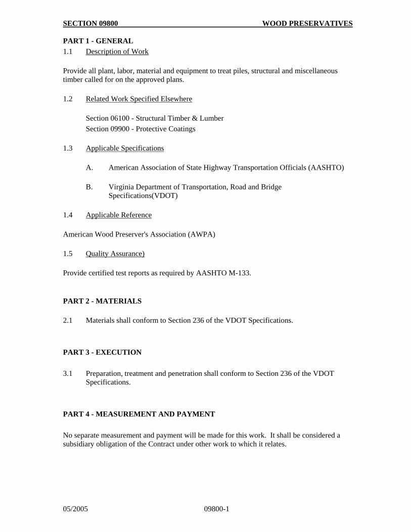
SECTION 09800 WOOD PRESERVATIVES
05/2005 09800-1
PART 1 - GENERAL
1.1 Description of Work
Provide all plant, labor, material and equipment to treat piles, structural and miscellaneous timber called for on the approved plans.
1.2 Related Work Specified Elsewhere
Section 06100 - Structural Timber & Lumber
Section 09900 - Protective Coatings
1.3 Applicable Specifications
A. American Association of State Highway Transportation Officials (AASHTO)
B. Virginia Department of Transportation, Road and Bridge
Specifications(VDOT)
1.4 Applicable Reference
American Wood Preserver's Association (AWPA)
1.5 Quality Assurance)
Provide certified test reports as required by AASHTO M-133.
PART 2 - MATERIALS
2.1 Materials shall conform to Section 236 of the VDOT Specifications.
PART 3 - EXECUTION
3.1 Preparation, treatment and penetration shall conform to Section 236 of the VDOT Specifications.
PART 4 - MEASUREMENT AND PAYMENT
No separate measurement and payment will be made for this work. It shall be considered a subsidiary obligation of the Contract under other work to which it relates.

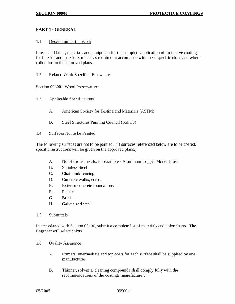
SECTION 09900 PROTECTIVE COATINGS
05/2005 09900-1
PART 1 - GENERAL
1.1 Description of the Work
Provide all labor, materials and equipment for the complete application of protective coatings for interior and exterior surfaces as required in accordance with these specifications and where called for on the approved plans.
1.2 Related Work Specified Elsewhere
Section 09800 - Wood Preservatives
1.3 Applicable Specifications
A. American Society for Testing and Materials (ASTM)
B. Steel Structures Painting Council (SSPC0)
1.4 Surfaces Not to be Painted
The following surfaces are not to be painted. (If surfaces referenced below are to be coated, specific instructions will be given on the approved plans.)
A. Non-ferrous metals; for example - Aluminum Copper Monel Brass
B. Stainless Steel
C. Chain link fencing
D. Concrete walks, curbs
E. Exterior concrete foundations
F. Plastic
G. Brick
H. Galvanized steel
1.5 Submittals
In accordance with Section 03100, submit a complete list of materials and color charts. The Engineer will select colors.
1.6 Quality Assurance
A. Primers, intermediate and top coats for each surface shall be supplied by one
manufacturer.
B. Thinner, solvents, cleaning compounds shall comply fully with the
recommendations of the coatings manufacturer.
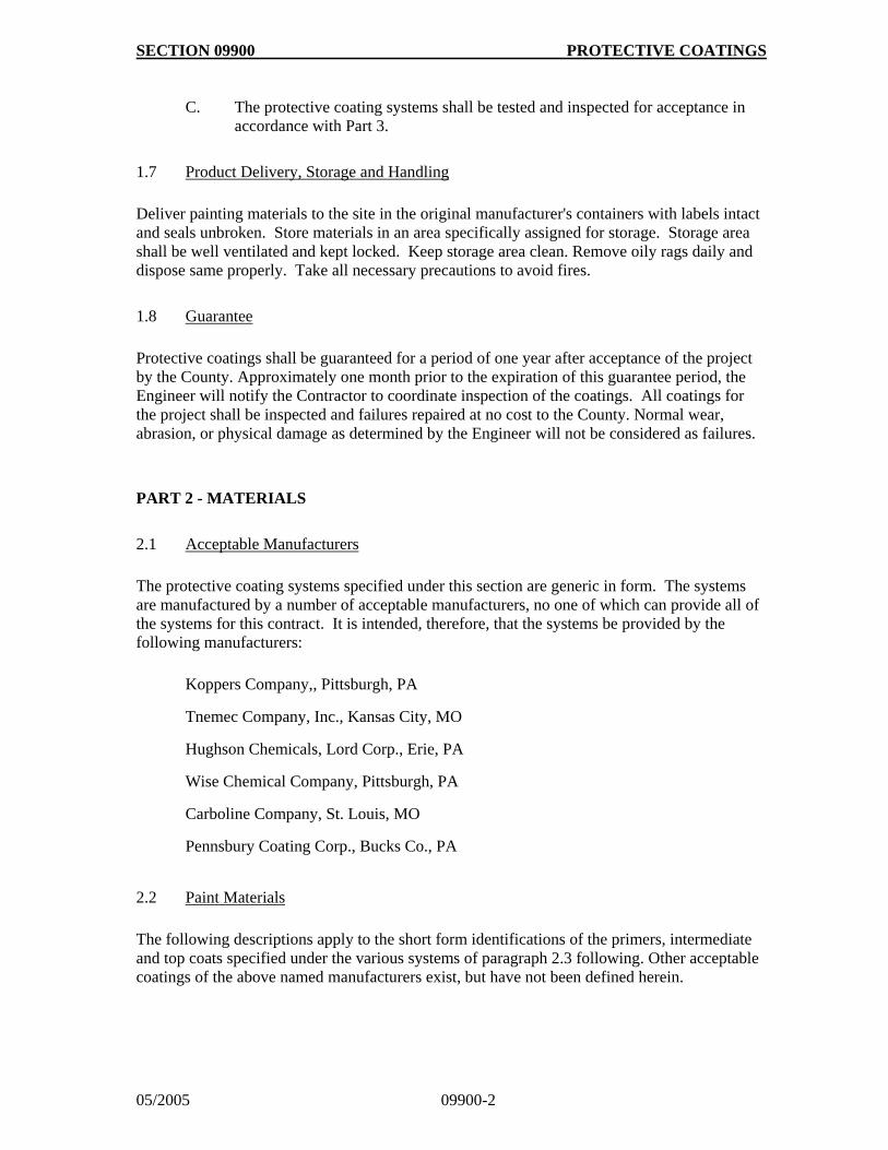
SECTION 09900 PROTECTIVE COATINGS
05/2005 09900-2
C. The protective coating systems shall be tested and inspected for acceptance in
accordance with Part 3.
1.7 Product Delivery, Storage and Handling
Deliver painting materials to the site in the original manufacturer's containers with labels intact and seals unbroken. Store materials in an area specifically assigned for storage. Storage area shall be well ventilated and kept locked. Keep storage area clean. Remove oily rags daily and dispose same properly. Take all necessary precautions to avoid fires.
1.8 Guarantee
Protective coatings shall be guaranteed for a period of one year after acceptance of the project by the County. Approximately one month prior to the expiration of this guarantee period, the Engineer will notify the Contractor to coordinate inspection of the coatings. All coatings for the project shall be inspected and failures repaired at no cost to the County. Normal wear, abrasion, or physical damage as determined by the Engineer will not be considered as failures.
PART 2 - MATERIALS
2.1 Acceptable Manufacturers
The protective coating systems specified under this section are generic in form. The systems are manufactured by a number of acceptable manufacturers, no one of which can provide all of the systems for this contract. It is intended, therefore, that the systems be provided by the following manufacturers:
Koppers Company,, Pittsburgh, PA
Tnemec Company, Inc., Kansas City, MO
Hughson Chemicals, Lord Corp., Erie, PA
Wise Chemical Company, Pittsburgh, PA
Carboline Company, St. Louis, MO
Pennsbury Coating Corp., Bucks Co., PA
2.2 Paint Materials
The following descriptions apply to the short form identifications of the primers, intermediate and top coats specified under the various systems of paragraph 2.3 following. Other acceptable coatings of the above named manufacturers exist, but have not been defined herein.
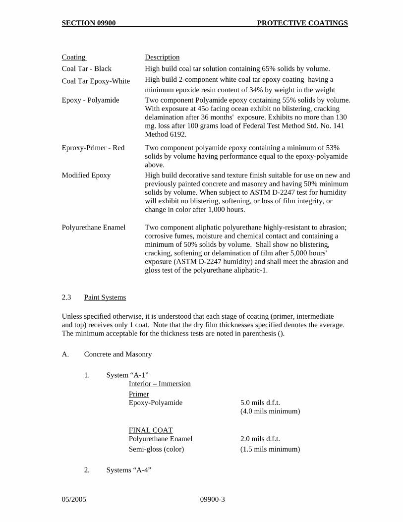
SECTION 09900 PROTECTIVE COATINGS
05/2005 09900-3
Coating Description
Coal Tar - Black High build coal tar solution containing 65% solids by volume.
Coal Tar Epoxy-White High build 2-component white coal tar epoxy coating having a
minimum epoxide resin content of 34% by weight in the weight Epoxy - Polyamide Two component Polyamide epoxy containing 55% solids by volume.
With exposure at 45o facing ocean exhibit no blistering, cracking delamination after 36 months' exposure. Exhibits no more than 130 mg. loss after 100 grams load of Federal Test Method Std. No. 141 Method 6192.
Eproxy-Primer - Red Two component polyamide epoxy containing a minimum of 53% solids by volume having performance equal to the epoxy-polyamide above.
Modified Epoxy High build decorative sand texture finish suitable for use on new and previously painted concrete and masonry and having 50% minimum solids by volume. When subject to ASTM D-2247 test for humidity will exhibit no blistering, softening, or loss of film integrity, or change in color after 1,000 hours.
Polyurethane Enamel Two component aliphatic polyurethane highly-resistant to abrasion; corrosive fumes, moisture and chemical contact and containing a minimum of 50% solids by volume. Shall show no blistering, cracking, softening or delamination of film after 5,000 hours' exposure (ASTM D-2247 humidity) and shall meet the abrasion and gloss test of the polyurethane aliphatic-1.
2.3 Paint Systems
Unless specified otherwise, it is understood that each stage of coating (primer, intermediate and top) receives only 1 coat. Note that the dry film thicknesses specified denotes the average. The minimum acceptable for the thickness tests are noted in parenthesis ().
A. Concrete and Masonry
1. System “A-1” Interior – Immersion
Primer Epoxy-Polyamide 5.0 mils d.f.t. (4.0 mils minimum)
FINAL COAT Polyurethane Enamel 2.0 mils d.f.t.
Semi-gloss (color) (1.5 mils minimum)
2. Systems “A-4”
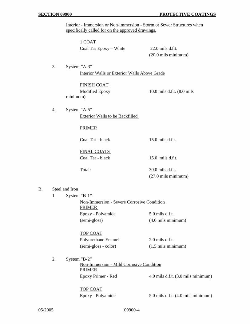
SECTION 09900 PROTECTIVE COATINGS
05/2005 09900-4
Interior - Immersion or Non-immersion - Storm or Sewer Structures when specifically called for on the approved drawings.
1 COAT
Coal Tar Epoxy – White 22.0 mils d.f.t.
(20.0 mils minimum)
3. System ”A-3”
Interior Walls or Exterior Walls Above Grade
FINISH COAT
Modified Epoxy 10.0 mils d.f.t. (8.0 mils minimum)
4. System “A-5”
Exterior Walls to be Backfilled
PRIMER
Coal Tar - black 15.0 mils d.f.t.
FINAL COATS
Coal Tar - black 15.0 mils d.f.t.
Total: 30.0 mils d.f.t.
(27.0 mils minimum)
B. Steel and Iron
1. System “B-1”
Non-Immersion - Severe Corrosive Condition PRIMER
Epoxy - Polyamide 5.0 mils d.f.t.
(semi-gloss) (4.0 mils minimum)
TOP COAT
Polyurethane Enamel 2.0 mils d.f.t.
(semi-gloss - color) (1.5 mils minimum)
2. System ”B-2” Non-Immersion - Mild Corrosive Condition PRIMER
Epoxy Primer - Red 4.0 mils d.f.t. (3.0 mils minimum)
TOP COAT
Epoxy - Polyamide 5.0 mils d.f.t. (4.0 mils minimum)
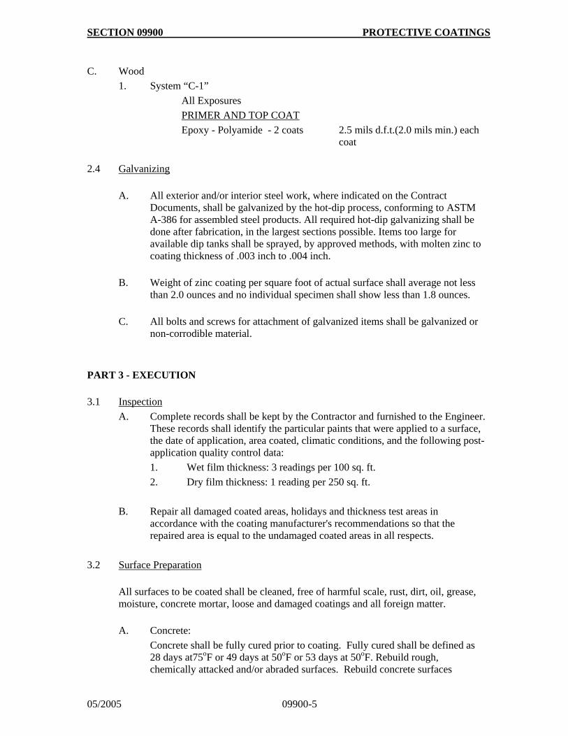
SECTION 09900 PROTECTIVE COATINGS
05/2005 09900-5
C. Wood
1. System “C-1”
All Exposures
PRIMER AND TOP COAT
Epoxy - Polyamide - 2 coats 2.5 mils d.f.t.(2.0 mils min.) each coat
2.4 Galvanizing
A. All exterior and/or interior steel work, where indicated on the Contract
Documents, shall be galvanized by the hot-dip process, conforming to ASTM A-386 for assembled steel products. All required hot-dip galvanizing shall be done after fabrication, in the largest sections possible. Items too large for available dip tanks shall be sprayed, by approved methods, with molten zinc to coating thickness of .003 inch to .004 inch.
B. Weight of zinc coating per square foot of actual surface shall average not less
than 2.0 ounces and no individual specimen shall show less than 1.8 ounces.
C. All bolts and screws for attachment of galvanized items shall be galvanized or
non-corrodible material.
PART 3 - EXECUTION
3.1 Inspection
A. Complete records shall be kept by the Contractor and furnished to the Engineer. These records shall identify the particular paints that were applied to a surface, the date of application, area coated, climatic conditions, and the following post-application quality control data:
1. Wet film thickness: 3 readings per 100 sq. ft.
2. Dry film thickness: 1 reading per 250 sq. ft.
B. Repair all damaged coated areas, holidays and thickness test areas in accordance with the coating manufacturer's recommendations so that the repaired area is equal to the undamaged coated areas in all respects.
3.2 Surface Preparation
All surfaces to be coated shall be cleaned, free of harmful scale, rust, dirt, oil, grease, moisture, concrete mortar, loose and damaged coatings and all foreign matter.
A. Concrete:
Concrete shall be fully cured prior to coating. Fully cured shall be defined as 28 days at75oF or 49 days at 50oF or 53 days at 50oF. Rebuild rough, chemically attacked and/or abraded surfaces. Rebuild concrete surfaces
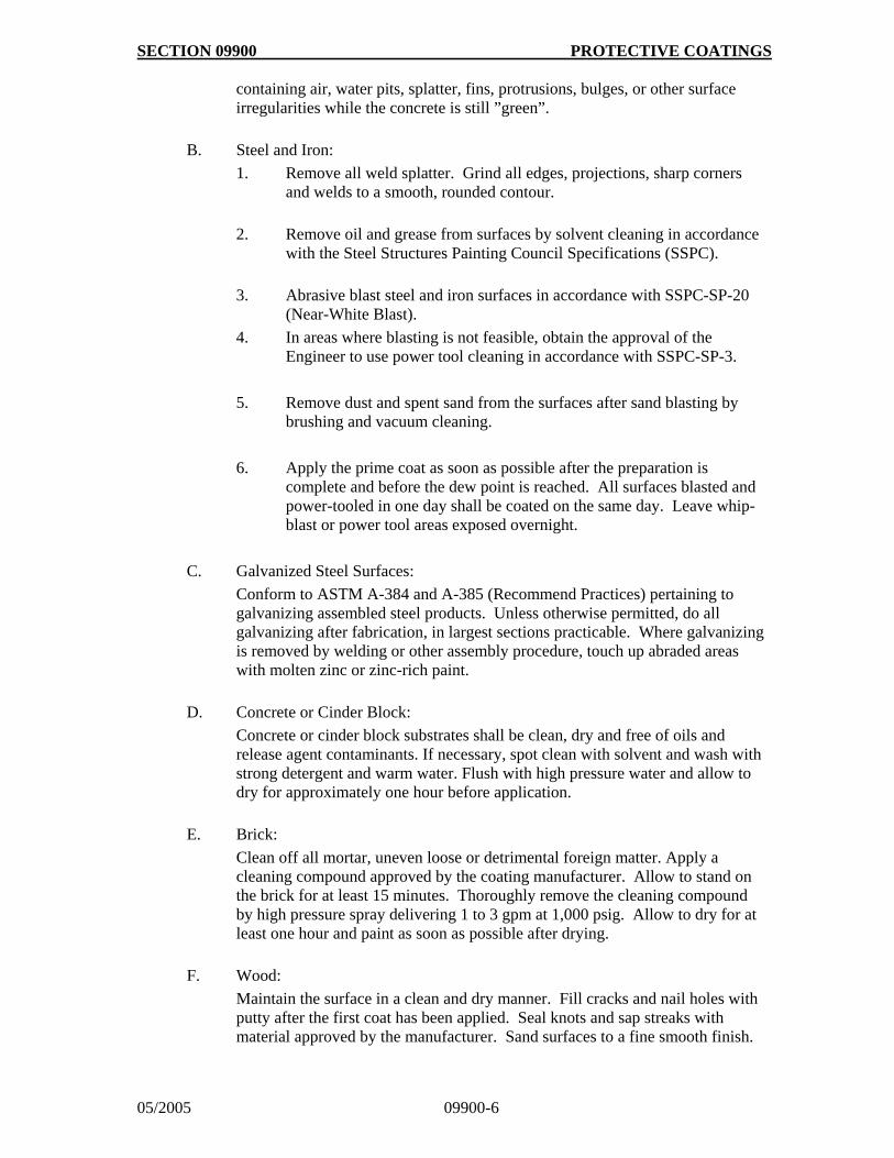
SECTION 09900 PROTECTIVE COATINGS
05/2005 09900-6
containing air, water pits, splatter, fins, protrusions, bulges, or other surface irregularities while the concrete is still ”green”.
B. Steel and Iron:
1. Remove all weld splatter. Grind all edges, projections, sharp corners and welds to a smooth, rounded contour.
2. Remove oil and grease from surfaces by solvent cleaning in accordance
with the Steel Structures Painting Council Specifications (SSPC).
3. Abrasive blast steel and iron surfaces in accordance with SSPC-SP-20
(Near-White Blast).
4. In areas where blasting is not feasible, obtain the approval of the Engineer to use power tool cleaning in accordance with SSPC-SP-3.
5. Remove dust and spent sand from the surfaces after sand blasting by brushing and vacuum cleaning.
6. Apply the prime coat as soon as possible after the preparation is complete and before the dew point is reached. All surfaces blasted and power-tooled in one day shall be coated on the same day. Leave whip-blast or power tool areas exposed overnight.
C. Galvanized Steel Surfaces:
Conform to ASTM A-384 and A-385 (Recommend Practices) pertaining to galvanizing assembled steel products. Unless otherwise permitted, do all galvanizing after fabrication, in largest sections practicable. Where galvanizing is removed by welding or other assembly procedure, touch up abraded areas with molten zinc or zinc-rich paint.
D. Concrete or Cinder Block:
Concrete or cinder block substrates shall be clean, dry and free of oils and release agent contaminants. If necessary, spot clean with solvent and wash with strong detergent and warm water. Flush with high pressure water and allow to dry for approximately one hour before application.
E. Brick:
Clean off all mortar, uneven loose or detrimental foreign matter. Apply a cleaning compound approved by the coating manufacturer. Allow to stand on the brick for at least 15 minutes. Thoroughly remove the cleaning compound by high pressure spray delivering 1 to 3 gpm at 1,000 psig. Allow to dry for at least one hour and paint as soon as possible after drying.
F. Wood:
Maintain the surface in a clean and dry manner. Fill cracks and nail holes with putty after the first coat has been applied. Seal knots and sap streaks with material approved by the manufacturer. Sand surfaces to a fine smooth finish.
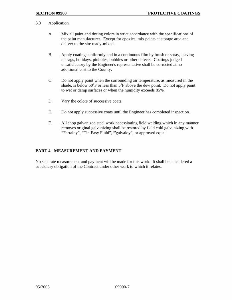
SECTION 09900 PROTECTIVE COATINGS
05/2005 09900-7
3.3 Application
A. Mix all paint and tinting colors in strict accordance with the specifications of
the paint manufacturer. Except for epoxies, mix paints at storage area and deliver to the site ready-mixed.
B. Apply coatings uniformly and in a continuous film by brush or spray, leaving
no sags, holidays, pinholes, bubbles or other defects. Coatings judged unsatisfactory by the Engineer's representative shall be corrected at no additional cost to the County.
C. Do not apply paint when the surrounding air temperature, as measured in the
shade, is below 50oF or less than 5oF above the dew point. Do not apply paint to wet or damp surfaces or when the humidity exceeds 85%.
D. Vary the colors of successive coats.
E. Do not apply successive coats until the Engineer has completed inspection.
F. All shop galvanized steel work necessitating field welding which in any manner
removes original galvanizing shall be restored by field cold galvanizing with “Ferraloy”, “Tin Easy Fluid”, “'galvaloy”, or approved equal.
PART 4 - MEASUREMENT AND PAYMENT
No separate measurement and payment will be made for this work. It shall be considered a subsidiary obligation of the Contract under other work to which it relates.

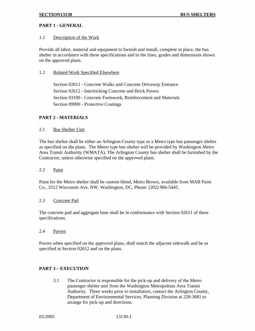
SECTION13130 BUS SHELTERS
05/2005 13130-1
PART 1 - GENERAL
1.1 Description of the Work
Provide all labor, material and equipment to furnish and install, complete in place, the bus shelter in accordance with these specifications and to the lines, grades and dimensions shown on the approved plans.
1.2 Related Work Specified Elsewhere
Section 02611 - Concrete Walks and Concrete Driveway Entrance
Section 02612 - Interlocking Concrete and Brick Pavers
Section 03100 - Concrete Formwork, Reinforcement and Materials
Section 09900 - Protective Coatings
PART 2 - MATERIALS
2.1 Bus Shelter Unit
The bus shelter shall be either an Arlington County type or a Metro type bus passenger shelter as specified on the plans. The Metro type bus shelter will be provided by Washington Metro Area Transit Authority (WMATA). The Arlington County bus shelter shall be furnished by the Contractor, unless otherwise specified on the approved plans.
2.2 Paint
Paint for the Metro shelter shall be custom blend, Metro Brown, available from MAB Paint Co., 3312 Wisconsin Ave. NW, Washington, DC, Phone: (202) 966-5445.
2.3 Concrete Pad
The concrete pad and aggregate base shall be in conformance with Section 02611 of these specifications.
2.4 Pavers
Pavers when specified on the approved plans, shall match the adjacent sidewalk and be as specified in Section 02612 and on the plans.
PART 3 – EXECUTION
3.1 The Contractor is responsible for the pick-up and delivery of the Metro
passenger shelter unit from the Washington Metropolitan Area Transit Authority. Three weeks prior to installation, contact the Arlington County, Department of Environmental Services, Planning Division at 228-3681 to arrange for pick-up and directions.
SECTION13130 BUS SHELTERS
05/2005 13130-2
3.2 The unit is to be mounted on a 4-inch thick concrete pad on a 3-inch compacted
aggregate base. Construct concrete pad in accordance with Section 02611. When pavers are specified on approved plans, lay pavers in accordance with Section 02612. Match elevation of pavers or concrete pad with adjacent sidewalk and provide 1/4-inch/ft positive drainage to street. Extend anchor bolts from concrete base pad through pavers to mount on shelter brackets.
3.3 Install bus shelter in accordance with the approved plans and the details
provided in these specifications.
3.4 Paint the Metro bus shelter in accordance with Section 09900 and
manufacturer's application instructions.
PART 4 - MEASUREMENT AND PAYMENT
Bus shelters shall be measured as each. Payment will be at the unit price stated in the bid proposal and shall include all materials, labor and incidentals necessary for a complete installation of the bus shelter unit and the supporting concrete pad.
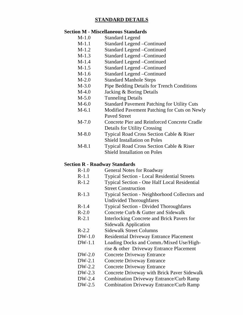
STANDARD DETAILS Section M - Miscellaneous Standards
M-1.0 Standard Legend M-1.1 Standard Legend –Continued M-1.2 Standard Legend –Continued M-1.3 Standard Legend –Continued M-1.4 Standard Legend –Continued M-1.5 Standard Legend –Continued M-1.6 Standard Legend –Continued M-2.0 Standard Manhole Steps M-3.0 Pipe Bedding Details for Trench Conditions M-4.0 Jacking & Boring Details M-5.0 Tunneling Details M-6.0 Standard Pavement Patching for Utility Cuts M-6.1 Modified Pavement Patching for Cuts on Newly
Paved Street M-7.0 Concrete Pier and Reinforced Concrete Cradle
Details for Utility Crossing M-8.0 Typical Road Cross Section Cable & Riser
Shield Installation on Poles M-8.1 Typical Road Cross Section Cable & Riser
Shield Installation on Poles Section R - Roadway Standards
R-1.0 General Notes for Roadway R-1.1 Typical Section - Local Residential Streets R-1.2 Typical Section - One Half Local Residential
Street Construction R-1.3 Typical Section - Neighborhood Collectors and
Undivided Thoroughfares R-1.4 Typical Section - Divided Thoroughfares R-2.0 Concrete Curb & Gutter and Sidewalk R-2.1 Interlocking Concrete and Brick Pavers for
Sidewalk Application R-2.2 Sidewalk Street Columns DW-1.0 Residential Driveway Entrance Placement DW-1.1 Loading Docks and Comm./Mixed Use/High-
rise & other Driveway Entrance Placement DW-2.0 Concrete Driveway Entrance DW-2.1 Concrete Driveway Entrance DW-2.2 Concrete Driveway Entrance DW-2.3 Concrete Driveway with Brick Paver Sidewalk DW-2.4 Combination Driveway Entrance/Curb Ramp DW-2.5 Combination Driveway Entrance/Curb Ramp
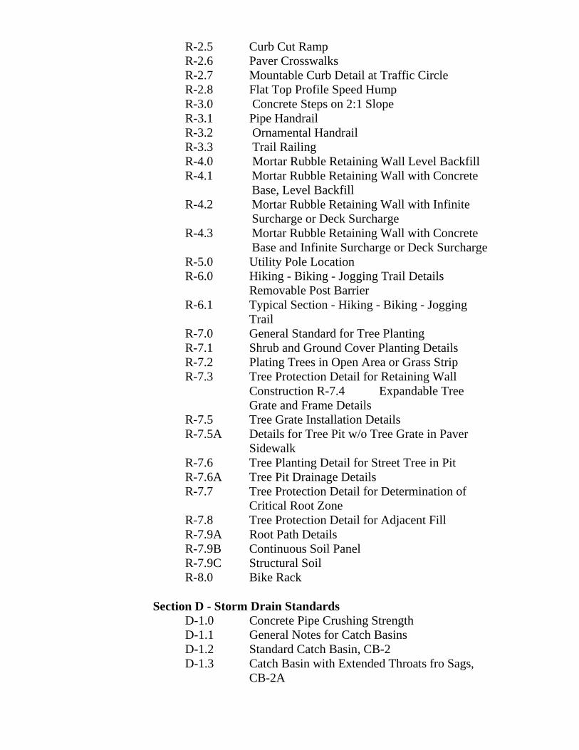
R-2.5 Curb Cut Ramp R-2.6 Paver Crosswalks R-2.7 Mountable Curb Detail at Traffic Circle R-2.8 Flat Top Profile Speed Hump R-3.0 Concrete Steps on 2:1 Slope R-3.1 Pipe Handrail R-3.2 Ornamental Handrail R-3.3 Trail Railing R-4.0 Mortar Rubble Retaining Wall Level Backfill R-4.1 Mortar Rubble Retaining Wall with Concrete
Base, Level Backfill R-4.2 Mortar Rubble Retaining Wall with Infinite
Surcharge or Deck Surcharge R-4.3 Mortar Rubble Retaining Wall with Concrete
Base and Infinite Surcharge or Deck Surcharge R-5.0 Utility Pole Location R-6.0 Hiking - Biking - Jogging Trail Details
Removable Post Barrier R-6.1 Typical Section - Hiking - Biking - Jogging
Trail R-7.0 General Standard for Tree Planting R-7.1 Shrub and Ground Cover Planting Details R-7.2 Plating Trees in Open Area or Grass Strip R-7.3 Tree Protection Detail for Retaining Wall
Construction R-7.4 Expandable Tree Grate and Frame Details
R-7.5 Tree Grate Installation Details R-7.5A Details for Tree Pit w/o Tree Grate in Paver
Sidewalk R-7.6 Tree Planting Detail for Street Tree in Pit R-7.6A Tree Pit Drainage Details R-7.7 Tree Protection Detail for Determination of
Critical Root Zone R-7.8 Tree Protection Detail for Adjacent Fill R-7.9A Root Path Details R-7.9B Continuous Soil Panel R-7.9C Structural Soil R-8.0 Bike Rack
Section D - Storm Drain Standards D-1.0 Concrete Pipe Crushing Strength D-1.1 General Notes for Catch Basins D-1.2 Standard Catch Basin, CB-2 D-1.3 Catch Basin with Extended Throats fro Sags,
CB-2A
D-1.4 Catch Basin with Extended Throats for Slopes, CB-2B
D-1.5 Precast Catch Basin, PCB-2 D-1.6 Details fro Precast Catch Basin, PCB-2 D-1.7 Catch Basin with Grate Top, CB-3 D-1.8 Catch Basin with Double Throat, CB-4 D-1.9 NonRoadway Shallow Grate Inlet 15" to 24"
Pipe Maximum D-1.10 Yard Inlet D-1.11 Precast Yard Inlet D-1.12 Driveway Grate D-1.13 Catch Basin Frame and Cover D-2.0 Manhole and Catch Basin Block D-2.1 Method for Shaping Manhole and Basin Inverts D-3.0 Storm Sewer Manhole, MH-1 for Pipe Sizes
15" through 36" D-3.1 Storm Sewer Precast Manhole, PMH-1 for Pipe
Sizes 15" through 36" D-3.2 Storm Sewer Manhole, MH-1 with Standard
CB-3 Grate Cover D-3.3 Storm Sewer Manhole, MH-2 for Pipe Sizes
42" through 54" D-3.4 Storm Sewer Manhole, MH-3 for Pipe Size
Greater than 54" D-3.5 Storm Sewer Manhole, MH-4 for Pipe Sizes
Greater than 24" and Alignment Changes Greater than 30"
D-3.6 Manhole Frame and Cover D-4.0 Gabion Revetment D-5.0 Temporary Vehicle Washrack D-5.1 Temporary Silt Fence D-5.2 Temporary Silt Fence Continued
Section W - Water Main Standards W-2.0 Concrete Thrust Blocks for Horizontal Bends W-2.1 Concrete Thrust Clocks for Tees and Caps W-2.2 Concrete Thrust Blocks for Lower Vertical
Bends W-2.3 Concrete Thrust Block Upper Vertical Bends W-2.4 Concrete Thrust Blocks Inserting Valves W-3.0 Restrained Joint Detail W-4.0 Blowoff Details W-5.0 Gate Valve Setting W-6.0 Air Release Valve W-6.1 Air and Vacuum Valve
W-7.0 Fire Hydrant Setting W-8.0 Water Service Connections 2-Inch and Smaller W-8.1 Water Service Connections 3-Inch and 4-Inch W-8.2 Water Service Connections 6-Inch and 8-Inch W-9.0 Water Meter installation 3/4-Inch and 1-Inch
Service W-9.1 Water Meter Installation 1 1/2-Inch Service W-9.2 Water Meter Installation 2-Inch Service W-9.3 Water Meter Installation 3-Inch Service W-9.4 Water Meter Installation 4-Inch Service W-9.5 Water Meter Installation 6-Inch Service W-9.6 Water Meter Installation 8-Inch Service W-9.7 22"x28" Frame and Cover for 24" I.D. Water
Meter Box W-9.8 24"x40" Frame and Cover for 36" I.D. Water
Meter Box W-9.9 36"x54" Frame and Cover for Concrete Water
Meter Vault W-10.0 Water Meter Fact Sheet
Section S - Sanitary Sewer Standards
S-2.0 Manhole Precast Concrete 4'-0" I.D. S-2.1 Manhole Precast Concrete 5'-0" & 6'-0" I.D. S-2.2 Manhole Construct Over Existing Sewer S-2.3 Sanitary Sewer Manhole with Outside Drop
Connection S-2.4 Manholes Channel and Foundations S-2.5 Manholes Adjustments to New Grades S-3.0 Manhole Frame and Cover 24-Inch Diameter
(MHC-1) S-3.1 Manhole Frame and Cover 24-Inch Bolted
(MHC-2) S-3.2 Manhole Frame and Cover 36-Inch Bolted
(MHC-3) S-4.0 PVC Sewer Pipe Installation Detail S-5.0 Maximum Allowable Backfill for Sanitary
Sewers S-6.0 Manhole Protection Detail


![Public Streetlight Design Guide[1]](https://static.fdocuments.net/doc/165x107/577cd8cc1a28ab9e78a202ab/public-streetlight-design-guide1.jpg)


