CONSTRUCTION SPECIFICATIONS - Bayfield OF BAYFIELD CONSTRUCTION SPECIFICATIONS Town of Bayfield P.O...
134
TOWN OF BAYFIELD CONSTRUCTION SPECIFICATIONS Town of Bayfield P.O Box 80 1199 Bayfield Parkway Bayfield, CO 81122 ADOPTED BY ORDINANCE NO. 374 Revised November 6, 2012 Phone: 970-884-9544 www.bayfieldgov.org Fax: 970-884-2195
Transcript of CONSTRUCTION SPECIFICATIONS - Bayfield OF BAYFIELD CONSTRUCTION SPECIFICATIONS Town of Bayfield P.O...

TOWN OF BAYFIELD
CONSTRUCTION SPECIFICATIONS
Town of Bayfield P.O Box 80
1199 Bayfield Parkway Bayfield, CO 81122
ADOPTED BY ORDINANCE NO. 374
Revised November 6, 2012
Phone: 970-884-9544 www.bayfieldgov.org Fax: 970-884-2195

Ordinance #374 i Revised November 6, 2012
TABLE OF CONTENTS SECTION 1 - GENERAL ........................................................................................................................................... 1
PART 1 GENERAL ................................................................................................................................................ 1 1.1 REVISIONS OF STANDARDS ............................................................................................................................ 1 1.2 PERMITS AND INSPECTION ............................................................................................................................. 1 1.3 RECORD DRAWINGS ......................................................................................................................................... 1
SECTION 2 - SITE PREPARATION AND EARTHWORK .................................................................................. 3 PART 1 GENERAL ................................................................................................................................................ 3
1.1 SUMMARY ........................................................................................................................................................... 3 1.2 QUALITY ASSURANCE ...................................................................................................................................... 3 1.3 APPLICABLE STANDARDS ............................................................................................................................... 3 1.4 SAMPLING AND TESTING ................................................................................................................................ 4 1.5 COMPLIANCE SUBMITTALS ............................................................................................................................ 4 1.6 JOB CONDITIONS................................................................................................................................................ 4 1.7 EROSION AND SEDIMENT CONTROLS .......................................................................................................... 4 1.8 DISPOSITION OF UTILITIES, STRUCTURES AND PROPERTY .................................................................... 4
PART 2 PRODUCTS ............................................................................................................................................. 5 2.1 FILL MATERIALS ................................................................................................................................................ 5 2.2 TOPSOIL MATERIALS ........................................................................................................................................ 5
PART 3 EXECUTION ............................................................................................................................................ 5 3.1 SITE PREPARATION ........................................................................................................................................... 5 3.2 EXCAVATION ...................................................................................................................................................... 5 3.3 EXCAVATION FOR STRUCTURES ................................................................................................................... 6 3.4 TRENCHING FOR UNDERGROUND UTILITIES ............................................................................................. 6 3.5 DEWATERING ..................................................................................................................................................... 6 3.6 DISPOSAL OF DEBRIS AND WASTE MATERIALS ........................................................................................ 7 3.7 SUBGRADE PREPARATION .............................................................................................................................. 7 3.8 FILLING AND BACKFILLING ........................................................................................................................... 7 3.9 SITE GRADING .................................................................................................................................................... 7 3.10 TOPSOIL PLACEMENT ....................................................................................................................................... 7 3.11 MAINTENANCE ................................................................................................................................................... 8
SECTION 3 - GENERAL UTILITY LINE INSTALLATION ............................................................................... 9 PART 1 GENERAL ................................................................................................................................................ 9
1.1 SUMMARY ........................................................................................................................................................... 9 1.2 APPLICABLE STANDARDS ............................................................................................................................... 9 1.3 PUBLIC SAFETY AND TRAFFIC ACCESS ....................................................................................................... 9 1.4 BARRICADES AND WARNING SIGNS ........................................................................................................... 10 1.5 LOCATION AND PROTECTION OF UTILITIES ............................................................................................. 10 1.6 INTERRUPTION OF WATER SERVICE .......................................................................................................... 10 1.7 REMOVAL OF PLANTINGS ............................................................................................................................. 10 1.8 MUD AND EARTH TRACKING ON PUBLIC STREETS ................................................................................ 10 1.9 MATERIALS REQUIREMENTS ........................................................................................................................ 10
PART 2 PRODUCTS ........................................................................................................................................... 11 2.1 CONCRETE AND MORTAR ............................................................................................................................. 11 2.2 BACKFILL AND BEDDING MATERIAL ......................................................................................................... 11
PART 3 EXECUTION .......................................................................................................................................... 13 3.1 UTILITY INSTALLATIONS IN PUBLIC STREETS ........................................................................................ 13 3.2 TRENCH EXCAVATION ................................................................................................................................... 13 3.3 BACKFILLING ................................................................................................................................................... 16 3.4 RESTORATION .................................................................................................................................................. 18
SECTION 4 - WATER DISTRIBUTION SYSTEMS ............................................................................................ 19 PART 1 GENERAL .............................................................................................................................................. 19
1.1 SUMMARY ......................................................................................................................................................... 19 1.2 APPLICABLE STANDARDS ............................................................................................................................. 19
PART 2 PRODUCTS ........................................................................................................................................... 20

Ordinance #374 ii Revised November 6, 2012
2.1 PIPE AND FITTINGS FOR WATER MAINS .................................................................................................... 20 2.2 APPURTENANCES FOR WATER DISTRIBUTION ........................................................................................ 21
PART 3 EXECUTION .......................................................................................................................................... 23 3.1 INSTALLATION OF WATER LINES, FORCE MAINS, SIPHONS AND OTHER PRESSURE PIPELINES 23 3.2 HYDROSTATIC TESTING OF PIPELINES ...................................................................................................... 26 3.3 DISINFECTION OF WATER LINES ................................................................................................................. 27 3.4 FINAL INSPECTION AND ACCEPTANCE ...................................................................................................... 28
SECTION 5 - SANITARY SEWER COLLECTION SYSTEMS ......................................................................... 29 PART 1 GENERAL .............................................................................................................................................. 29
1.1 SUMMARY ......................................................................................................................................................... 29 1.2 QUALITY STANDARDS ................................................................................................................................... 29
PART 2 PRODUCTS ........................................................................................................................................... 29 2.1 PIPE AND FITTINGS FOR SANITARY SEWER CONSTRUCTION .............................................................. 29 2.2 MANHOLES FOR SANITARY SEWERS.......................................................................................................... 30
PART 3 EXECUTION .......................................................................................................................................... 32 3.1 INSTALLATION OF SANITARY SEWERS ..................................................................................................... 32 3.2 TESTING ............................................................................................................................................................. 35 3.3 FINAL INSPECTION AND ACCEPTANCE ...................................................................................................... 37
SECTION 6 - STORM DRAINAGE FACILITIES ................................................................................................ 38 PART 1 GENERAL .............................................................................................................................................. 38
1.1 SUMMARY ......................................................................................................................................................... 38 PART 2 PRODUCTS ........................................................................................................................................... 38
2.1 PIPE AND FITTINGS FOR STORM SEWERS, CULVERTS AND SIPHONS ................................................ 38 2.2 MANHOLES, INLETS AND VAULTS FOR STORM SEWERS ...................................................................... 38
PART 3 EXECUTION .......................................................................................................................................... 39 3.1 INSTALLATION OF STORM DRAINAGE FACILITIES ................................................................................. 39 3.2 TESTING ............................................................................................................................................................. 40 3.3 FINAL INSPECTION AND ACCEPTANCE ...................................................................................................... 40
SECTION 7 - STREETS AND ROADS .................................................................................................................. 41 PART 1 GENERAL .............................................................................................................................................. 41
1.1 SUMMARY ......................................................................................................................................................... 41 1.2 NEW PROJECTS ................................................................................................................................................. 41 1.3 REHABILITATION AND REPAIR PROJECTS ................................................................................................ 41 1.4 ASPHALT PEDESTRIAN AND BICYCLE PATHWAYS ................................................................................ 42 1.5 TESTING ............................................................................................................................................................. 42 1.6 ROADWAY EXCAVATION AND GRADING ................................................................................................. 42 1.7 CLEARING .......................................................................................................................................................... 42 1.8 GRUBBING ......................................................................................................................................................... 43 1.9 STRIPPING .......................................................................................................................................................... 43 1.10 EXCAVATION .................................................................................................................................................... 43 1.11 SHOULDERING AND MISCELLANEOUS WORK ......................................................................................... 44 1.12 EMBANKMENTS ............................................................................................................................................... 44 1.13 SUBGRADE PREPARATION ............................................................................................................................ 45 1.14 BASE COURSE AGGREGATE .......................................................................................................................... 45 1.15 BASE COURSE PLACEMENT AND COMPACTION ...................................................................................... 45 1.16 PLANT MIX HOT BITUMINOUS PAVEMENT ............................................................................................... 47 1.17 TESTING ............................................................................................................................................................. 47
PART 2 PRODUCTS ........................................................................................................................................... 48 2.1 MATERIALS ....................................................................................................................................................... 48 2.2 JOB MIX .............................................................................................................................................................. 49
PART 3 EXECUTION .......................................................................................................................................... 49 3.1 PREPARING AREA TO BE PAVED.................................................................................................................. 49 3.2 BITUMINOUS MIXING PLANT ....................................................................................................................... 50 3.3 BITUMINOUS PAVERS ..................................................................................................................................... 50 3.4 MIXTURE PLACEMENT ................................................................................................................................... 51
Ordinance #374 iii Revised November 6, 2012
3.5 COMPACTION.................................................................................................................................................... 52 3.6 JOINTS ................................................................................................................................................................ 52 3.7 SURFACE TOLERANCES ................................................................................................................................. 53 3.8 MANHOLES AND VALVE BOXES .................................................................................................................. 53 3.9 ACCEPTANCE REQUIREMENTS .................................................................................................................... 53 3.10 INSPECTION AND ACCEPTANCE OF WORK ............................................................................................... 54 3.11 CONTRACTOR’S GUARANTEE ...................................................................................................................... 54
SECTION 8 - CONCRETE CURB, GUTTER AND SIDEWALK ....................................................................... 55 PART 1 GENERAL .............................................................................................................................................. 55
1.1 SUMMARY ......................................................................................................................................................... 55 1.2 SEQUENCE OF CONSTRUCTION.................................................................................................................... 55
PART 2 PRODUCTS ........................................................................................................................................... 55 2.1 CEMENT ............................................................................................................................................................. 55 2.2 CONCRETE ......................................................................................................................................................... 55 2.3 AGGREGATE...................................................................................................................................................... 56 2.4 WATER ................................................................................................................................................................ 56 2.5 EXPANSION JOINT MATERIAL ...................................................................................................................... 56 2.6 PLASTIC FILM ................................................................................................................................................... 57 2.7 CURING COMPOUND ....................................................................................................................................... 57 2.8 FORMS ................................................................................................................................................................ 57 2.9 AGGREGATE BASE COURSE .......................................................................................................................... 57 2.10 TESTS .................................................................................................................................................................. 57
PART 3 EXECUTION .......................................................................................................................................... 58 3.1 SUBGRADE PREPARATION ............................................................................................................................ 58 3.2 AGGREGATE BASE COURSE PREPARATION .............................................................................................. 59 3.3 CONCRETE MIXING ......................................................................................................................................... 59 3.4 RETEMPERING OF CONCRETE ...................................................................................................................... 60 3.5 PLACING CONCRETE ....................................................................................................................................... 60 3.6 SPACING OF JOINTS ......................................................................................................................................... 60 3.7 FINISHING .......................................................................................................................................................... 61 3.8 FORMING MACHINE PLACEMENT ............................................................................................................... 62 3.9 CURING .............................................................................................................................................................. 62 3.10 LIQUID MEMBRANE FORMING CURING COMPOUND ............................................................................. 62 3.11 PLASTIC FILM ................................................................................................................................................... 62 3.12 COLD WEATHER CONCRETING .................................................................................................................... 63 3.13 HOT WEATHER CONCRETING ....................................................................................................................... 64 3.14 OPENING TO TRAFFIC ..................................................................................................................................... 64 3.15 DAMAGE TO EXISTING PAVEMENT ............................................................................................................ 64 3.16 REPAIRS OF EXISTING SIDEWALKS ............................................................................................................ 64 3.17 BACKFILLING ................................................................................................................................................... 65 3.18 CLEANUP ........................................................................................................................................................... 65 3.19 ACCEPTANCE BY TOWN ................................................................................................................................ 65
SECTION 9 - CONCRETE FORMWORK ............................................................................................................ 66 PART 1 GENERAL .............................................................................................................................................. 66
1.1 SUMMARY ......................................................................................................................................................... 66 1.2 QUALITY STANDARDS ................................................................................................................................... 66 1.3 SUBMITTALS ..................................................................................................................................................... 66
PART 2 PRODUCTS ........................................................................................................................................... 66 2.1 MATERIALS ....................................................................................................................................................... 66
PART 3 EXECUTION .......................................................................................................................................... 67 3.1 DESIGN OF FORMWORK ................................................................................................................................. 67 3.2 CONSTRUCTION OF FORMS ........................................................................................................................... 67 3.3 INSPECTION ....................................................................................................................................................... 68 3.4 FORM REMOVAL .............................................................................................................................................. 68 3.5 REUSE OF FORMS ............................................................................................................................................. 68 3.6 QUALITY CONTROL ........................................................................................................................................ 68 3.7 CLEAN UP .......................................................................................................................................................... 68

Ordinance #374 iv Revised November 6, 2012
SECTION 10 - CONCRETE REINFORCEMENT ................................................................................................ 69 PART 1 GENERAL .............................................................................................................................................. 69
1.1 SUMMARY ......................................................................................................................................................... 69 1.2 QUALITY STANDARDS ................................................................................................................................... 69 1.3 SUBMITTALS ..................................................................................................................................................... 69
PART 2 PRODUCTS ........................................................................................................................................... 69 2.1 MATERIALS ....................................................................................................................................................... 69
PART 3 EXECUTION .......................................................................................................................................... 70 3.1 QUALITY CONTROL ........................................................................................................................................ 70 3.2 CLEAN UP .......................................................................................................................................................... 70
SECTION 11 - JOINTS IN CONCRETE ................................................................................................................ 71 PART 1 GENERAL .............................................................................................................................................. 71
1.1 SUMMARY ......................................................................................................................................................... 71 1.2 QUALITY STANDARDS ................................................................................................................................... 71 1.3 SUBMITTALS ..................................................................................................................................................... 71
PART 2 PRODUCTS ........................................................................................................................................... 71 2.1 MATERIALS ....................................................................................................................................................... 71
PART 3 EXECUTION .......................................................................................................................................... 72 3.1 CONSTRUCTION JOINTS ................................................................................................................................. 72 3.2 EXPANSION AND CONTRACTION JOINTS .................................................................................................. 72 3.3 WATERTIGHT JOINTS ...................................................................................................................................... 72 3.4 QUALITY CONTROL ........................................................................................................................................ 73
SECTION 12 - CAST-IN-PLACE CONCRETE .................................................................................................... 74 PART 1 GENERAL .............................................................................................................................................. 74
1.1 SUMMARY ......................................................................................................................................................... 74 1.2 QUALITY STANDARDS ................................................................................................................................... 74 1.3 SUBMITTALS ..................................................................................................................................................... 75
PART 2 PRODUCTS ........................................................................................................................................... 75 2.1 CONCRETE ......................................................................................................................................................... 75 2.2 AGGREGATES ................................................................................................................................................... 76 2.3 ADMIXTURES .................................................................................................................................................... 76 2.4 PROPORTIONING .............................................................................................................................................. 76 2.5 MIXING ............................................................................................................................................................... 76 2.6 GROUT ................................................................................................................................................................ 76
PART 3 EXECUTION .......................................................................................................................................... 77 3.1 SUBGRADE PREPARATION ............................................................................................................................ 77 3.2 CONCRETE PLACEMENT ................................................................................................................................ 77 3.3 FINISHING .......................................................................................................................................................... 79 3.4 PROTECTION ..................................................................................................................................................... 81 3.5 CURING .............................................................................................................................................................. 81 3.6 DELIVERY, STORAGE AND HANDLING OF MATERIALS ......................................................................... 82 3.7 TESTING ............................................................................................................................................................. 82 3.8 ACCEPTANCE OF CONCRETE ........................................................................................................................ 82 3.9 REPAIRING CONCRETE ................................................................................................................................... 82 3.10 CLEAN UP .......................................................................................................................................................... 83
SECTION 13 - REINFORCED CONCRETE MASONRY UNITS ...................................................................... 84 PART 1 GENERAL .............................................................................................................................................. 84
1.1 SUMMARY ......................................................................................................................................................... 84 1.2 PERMITS AND INSPECTION ........................................................................................................................... 84 1.3 QUALITY STANDARDS: .................................................................................................................................. 84 1.4 SUBMITTALS ..................................................................................................................................................... 84
PART 2 PRODUCTS ........................................................................................................................................... 85 2.1 MATERIALS ....................................................................................................................................................... 85
PART 3 EXECUTION .......................................................................................................................................... 85 3.1 MIXING ............................................................................................................................................................... 85

Ordinance #374 v Revised November 6, 2012
3.2 EXECUTION OF WORK .................................................................................................................................... 85 3.3 QUALITY CONTROL: ....................................................................................................................................... 86 3.4 CLEAN UP .......................................................................................................................................................... 86
SECTION 14 - STRUCTURAL METAL ................................................................................................................ 87 PART 1 GENERAL .............................................................................................................................................. 87
1.1 SUMMARY ......................................................................................................................................................... 87 1.2 QUALITY STANDARDS ................................................................................................................................... 87 1.3 SUBMITTALS ..................................................................................................................................................... 87 1.4 PERMITS AND INSPECTION ........................................................................................................................... 87
PART 2 PRODUCTS ........................................................................................................................................... 87 2.1 MATERIAL REQUIREMENTS .......................................................................................................................... 87
PART 3 EXECUTION .......................................................................................................................................... 88 3.1 EXECUTION OF THE WORK ........................................................................................................................... 88
SECTION 15 - LANDSCAPING .............................................................................................................................. 89 PART 1 GENERAL .............................................................................................................................................. 89
1.1 SUMMARY ......................................................................................................................................................... 89 1.2 QUALITY ASSURANCE .................................................................................................................................... 89 1.3 SUBMITTALS ..................................................................................................................................................... 89 1.4 DELIVERY, STORAGE AND HANDLING ...................................................................................................... 90 1.5 JOB CONDITION ................................................................................................................................................ 90 1.6 SPECIAL PROJECT WARRANTY: ................................................................................................................... 91
PART 2 PRODUCTS ........................................................................................................................................... 91 2.1 TOPSOIL ............................................................................................................................................................. 91 2.2 SOIL AMENDMENTS: ....................................................................................................................................... 91 2.3 PLANT MATERIALS ......................................................................................................................................... 92 2.4 GRASS MATERIAL............................................................................................................................................ 92
PART 3 EXECUTION .......................................................................................................................................... 94 3.1 PREPARATION .................................................................................................................................................. 94 3.2 PLANTING .......................................................................................................................................................... 95 3.3 SODDING NEW LAWNS ................................................................................................................................... 96 3.4 RECONDITION EXISTING LAWNS ................................................................................................................ 97 3.5 PLANTING GROUND COVER .......................................................................................................................... 97 3.6 MISCELLANEOUS LANDSCAPE WORK ....................................................................................................... 97 3.7 MAINTENANCE ................................................................................................................................................. 98 3.8 INSPECTION AND ACCEPTANCE .................................................................................................................. 98
STANDARD DETAIL DRAWINGS ....................................................................................................................... 99
Ordinance #345 1 Section 1 Revised November 6, 2012 General
SECTION 1
GENERAL
PART 1 GENERAL
1.1 REVISIONS OF STANDARDS
A. When reference is made to a Standard Specification (ASTM, AWWA, AASHTO, etc.), the specifications referred to shall be understood to mean the latest revision of said specification.
1.2 PERMITS AND INSPECTION
A. All required Federal, State, County, and Town permits shall be obtained before work begins. Work within the Town right-of-way (ROW) requires a ROW permit from the Town prior to initiating any work within the Town ROW.
B. The Contractor shall call for inspection from the Town of Bayfield, giving 48 hours minimum notice, before the placement of any material. In the event that any of the work or material fails to meet any of the requirements of the specifications, written notice of rejection shall be given to the Contractor and work shall be halted until such time as corrective action is taken.
C. A complete set of the approved drawings and a valid permit shall be on the job site and available to the Town representatives at all times.
D. The Contractor shall be licensed and bonded for work in the Town of Bayfield.
E. Inspection is only an aid to the Contractor and in no way reflects a responsibility on the part of the Town for quality or quantity control, and in no way implies acceptance of the work or any part thereof by the Town of Bayfield. In order to standardize the inspection and approval process, the Town will provide inspections forms. It is the responsibility of the Contractor to contact the Town regarding the required inspections as part of the project, and to arrange for the necessary inspections.
F. The Contractor shall not perform work on Saturday between the hours of 5 p.m. and 9 a.m., Sundays, town holidays, or between the hours of 7:00 p.m. and 7:00 a.m. on any working day, without written permission from the Town of Bayfield.
G. The Town may increase the number of required density tests by a minimum of one test of each type, up to a 10% increase, at locations of the Town’s choosing in order to provide confirmation of test results. The cost of the tests will be reimbursed by the Contractor.
1.3 RECORD DRAWINGS
A. It shall be the responsibility of the developer or contractor to provide the Town of Bayfield with a set of Record Drawings at the completion of the project verifying all elevations, all utility locations (including service line locations), including any changes from the approved construction plans that have occurred during construction.

Ordinance #345 2 Section 1 Revised November 6, 2012 General
B. As-built horizontal locations and elevations of utilities shall be established by a field survey after construction is complete for accessible utility structures (sewer and storm drain manholes, storm drain inlets, culverts, valve boxes, curb stops, fire hydrants, and other similar structures) and during construction for utility structures or features that are not accessible after backfilling (service line locations at the tap and at the curb, water line and force main bends and deflections following street or easement alignments, unusual water line or force main depths at crossings with other utilities or through significant cut or fill sections, utilities provided by other utility providers, and conduit or casing pipe installed for future use. The field survey shall be performed by a surveyor selected by the Town and tied to NAD 83 and NAVD 88. The developer or contractor shall be responsible for coordinating the site visits by the surveyor. The developer shall be responsible for the costs of the “as-built” survey, as invoiced by the Town, and development of the Record Drawings from the survey data.
C. Three 24”x36” paper copies of the Record Drawings, stamped by a Colorado Licensed Professional Engineer or Architect, shall be submitted to the Town prior to final acceptance of public improvements. In addition, electronic drawings (CAD or GIS) of public utilities and streets, at a minimum, shall be submitted to the Town prior to final acceptance of the improvements.
END OF SECTION

Ordinance #345 3 Section 2 Revised November 6, 2012 Site Preparation and Earthwork
SECTION 2
SITE PREPARATION AND EARTHWORK
PART 1 GENERAL
1.1 SUMMARY
A. This section includes all excavating, trenching, filling, backfilling, compacting, grading and all related items necessary to complete the work indicated or specified.
1.2 QUALITY ASSURANCE
A. Specified samples and tests will be made in accordance with the standard methods as defined in the procedures and methods of the applicable standards.
1.3 APPLICABLE STANDARDS
A. American Society for Testing and Materials (ASTM).
1. ASTM C39 – Standard Test Method for Compressive Strength of Cylindrical Concrete Specimens
2. ASTM C88 – Standard Test Method for Soundness of Aggregate by use of Sodium Sulfate or Magnesium Sulfate
3. ASTM D1556 – Standard Test Method for Density and Unit Weight of Soil in Place by Sand-Cone Method
4. ASTM D1557 – Standard Test Methods for Laboratory Compaction Characteristics of Soil Using Modified Effort
5. ASTM D1241 – Standard Specification for Materials for Soil-Aggregate Sub-base, Base and Surface Courses
6. ASTM D2487 – Standard Practice for Classification of Soils for Engineering Purposes (Unified Soil Classification System)
7. ASTM D4253 – Standard Test Methods for Maximum Index Density and Unit Weight of Soils Using a Vibratory Table
8. ASTM D4254 – Standard Test Methods for Minimum Index Density and Unit Weight of Soils and Calculation of Relative Density
9. ASTM D4318 – Standard Test Methods for Liquid Limit, Plastic Limit, and Plasticity Index of Soils
10. ASTM D6938 – Standard Test Method for In-Place Density and Water Content of Soil and Soil-Aggregate by Nuclear Methods (Shallow Depth)
B. Occupational Safety and Health Administration (OSHA)
1. Part 1926 Safety and Health Regulations for Construction

Ordinance #345 4 Section 2 Revised November 6, 2012 Site Preparation and Earthwork
1.4 SAMPLING AND TESTING
A. Tests to determine conformance with all requirements of this specification for quality and properties of all Contractor-secured materials, including borrow materials (both on or off-site) proposed for use, shall be performed by an independent, commercial laboratory retained and compensated by the Town. The Contractor will be required to coordinate the scheduling of the tests with the testing service and will be required to reimburse the Town for the cost of the testing services. On-site and off-site quality control tests will be performed during construction to determine conformance with plans and specifications by an independent testing laboratory retained and compensated by the Contractor. A representative frequency of on-site and off-site tests is included as follows:
1. General Fill and Fill Beneath Structures – A minimum of one test per 500 square feet per lift.
2. Trenches and Granular Embedment – A minimum of one test per 300 linear feet of trench for every other lift.
1.5 COMPLIANCE SUBMITTALS
A. Shall include, but is not limited to, test results for laboratory testing of proposed fill, select fill materials, and granular fill to certify conformance with requirements of this specification.
1.6 JOB CONDITIONS
A. Lines and grades shall be as indicated on approved plans. The Town will furnish bench marks and reference points as necessary to permit the Contractor to lay out the work for Town projects. All bench marks, monuments and other reference points shall be carefully maintained and replaced as directed by the Contractor if disturbed or destroyed. Arrangements shall be made with the Town for entry to the site for the purpose of conducting additional subsurface investigations, including test borings, if the Contractor feels additional subsurface information is required.
1.7 EROSION AND SEDIMENT CONTROLS
A. Temporary erosion and sediment controls shall be furnished, installed, constructed and maintained as temporary measures to control erosion and minimize the siltation of intermittent streams and the pollution of private properties. Contractor shall submit an Erosion Control Plan to the Town, and shall provide and maintain erosion control facilities in accordance with the approved plan. Temporary erosion and sediment controls measures shall be maintained until an acceptable stand of vegetation is established, generally 70% of the pre-disturbance vegetation density, or as defined in the Erosion Control Plan.
1.8 DISPOSITION OF UTILITIES, STRUCTURES AND PROPERTY
A. All utilities, structures and property shall be adequately protected from damage, and shall be removed or relocated only as indicated or specified. Any inactive or abandoned utilities encountered in excavating and grading operations shall be reported and noted on as-built drawings.

Ordinance #345 5 Section 2 Revised November 6, 2012 Site Preparation and Earthwork
PART 2 PRODUCTS
2.1 FILL MATERIALS
A. Fill material shall be in accordance with each project specific geotechnical engineering study. In lieu of a geotechnical engineering report all fill materials shall be approved by the Public Works Director or the Town Engineer.
Materials suitable for use in pipe line trenches include material that is free of debris, roots, organic matter, frozen matter, coal, ashes or cinders, which is free of stone having any dimension greater than 2 inches and not more than 25% coarser than the ¾-inch sieve.
B. Structural fill used below structural elements, such as footings, slabs, pavements, and mats shall have a liquid limit not exceeding 30 and a plasticity index not exceeding 6 when tested in accordance with ASTM D4318 for that portion of material passing the No. 40 square-mesh sieve.
C. General fill and backfill materials shall be sufficiently friable to provide a dense mass free of voids and capable of satisfactory compaction. Material shall not contain material with a maximum dimension greater than one-half the depth of the layer to be compacted, or 4 inches, whichever is less. General fill material shall have a liquid limit not exceeding 45 or a plastic index not exceeding 12 when tested in accordance with ASTM D4318. Fill failing to meet required densities or moisture contents shall be removed or scarified and recompacted as necessary to achieve specified results. Removal of in-place material and replacement with approved new material will be required if scarifying and recompaction do not produce the required densities.
2.2 TOPSOIL MATERIALS
A. Materials obtained from the top 3 to 12 inches of excavation which are free from rocks and debris, and suitable for vegetative growth will be stockpiled in an area as directed by the Town. Topsoil shall be removed from areas within the limits of excavation and areas designated to receive compacted fill.
PART 3 EXECUTION
3.1 SITE PREPARATION
A. Clearing and grubbing shall be performed only in areas where indicated and as necessary to perform excavation and other work required. Precautions shall be taken to guard against movement or settlement of existing structures, and provide shoring and bracing as necessary.
3.2 EXCAVATION
A. Sheeting and bracing shall be designed, furnished, placed, maintained and subsequently removed as a system of temporary supports for cut and cover, open cut, or trench excavations, including bracing, dewatering and associated items to support the sides and ends of the excavation beyond construction right-of-ways, or as otherwise specified or indicated. Support systems and methods of excavation shall be designed to assure safety to the public, adjacent

Ordinance #345 6 Section 2 Revised November 6, 2012 Site Preparation and Earthwork
property and the completed work. All shoring shall be detailed and designed by a professional engineer registered in the State of Colorado. Underground utilities shall be exposed by hand or other excavation methods acceptable to the Town.
B. Shoring, sheeting and bracing shall meet the following requirements:
1. Prevent undermining and damage to all structures, buildings, underground utilities, pavement and slabs.
2. Excavation support system shall be designed to support lateral earth pressures, unrelieved hydrostatic pressures, utility loads, traffic and construction loads, and building and other surcharge loads to allow the safe and expeditious construction of the permanent structures without movement or settlement of the ground, and to prevent damage to or movement of adjacent buildings, structures, underground utilities, and other improvements.
3. Contractor shall remove and replace any existing structure or underground facility damaged during shoring and sheeting. Sheeting and bracing shall be removed as backfill progresses.
4. Contractor shall be solely responsible for proper installation, operation, maintenance, and any failure of any component of the system.
5. Shoring, sheeting and bracing shall meet the guidelines for the appropriate OSHA regulations.
3.3 EXCAVATION FOR STRUCTURES
A. Trim to neat lines where details call for concrete to be deposited against earth. Excavate by hand in areas where space and access will not permit use of machines. Notify the Town Engineer immediately when excavation has reached the depth indicated. Restore the bottom of excavation to proper elevation with granular bedding material in areas over excavated.
B. Excavations shall meet the guidelines for the soil classification and subsurface conditions as outlined in the appropriate OSHA regulations.
3.4 TRENCHING FOR UNDERGROUND UTILITIES
A. Contractor shall conform to all Federal, State and local requirements, including OSHA. Side walls shall be sloped, stepped, or shored, as required for stability. For trenches, excavation shall be to a depth sufficient to provide the minimum bedding requirements for the utility being placed. The depth shall be increased as necessary to remove unsuitable supporting materials. Rock fragments and materials disturbed during excavation or raveled from trench walls shall be removed. The proper subgrade shall be restored with trench stabilization material when over excavated.
3.5 DEWATERING
A. Contractor shall design and provide the dewatering system to eliminate water entering the excavation under hydrostatic head from the bottom and/or sides, if necessary. The contractor shall obtain a dewatering permit from the State of Colorado, as required. The Contractor shall provide a dewatering system of a sufficient size and capacity as required to control ground and surface water flow into the excavation and to allow all work to be installed in a dry condition.
Ordinance #345 7 Section 2 Revised November 6, 2012 Site Preparation and Earthwork
Grading around excavation shall be controlled to prevent surface water from flowing into excavation areas. Subgrade materials rendered unsuitable by excessive wetting shall be removed and replaced with approved backfill material. Contractor shall remove all dewatering equipment from the site, including related temporary electrical service.
3.6 DISPOSAL OF DEBRIS AND WASTE MATERIALS
A. Materials not indicated or specified to be relocated or returned to the Town shall be disposed of off site at a location arranged by the Contractor. Construction debris, such as concrete, trees, stumps, brush and construction trash shall be disposed of off the job site at an appropriate landfill or other location approved by the Town.
3.7 SUBGRADE PREPARATION
A. Excavate or fill as required to construct subgrades to the elevations and grades indicated. All unsuitable material shall be removed and replaced with acceptable fill material. Wetting, drying, shaping and compacting shall be performed as required to prepare subgrade. Subgrade shall be approved by the Town Engineer before placement of fill.
3.8 FILLING AND BACKFILLING
A. Construct fills to the contours and elevations indicated using suitable approved fill material. Fill shall be placed in 6-inch compacted layers, unless otherwise recommended in a project-specific geotechnical report. Each lift of cohesive material shall be compacted to 90% of maximum dry density within the moisture content of 2% below to 4% above optimum moisture as determined by the modified proctor method ASTM D1557, unless otherwise specified in a project-specific geotechnical report. Existing slopes steeper than 6:1 shall be benched prior to filling. Excavation shall be backfilled only after concrete has attained 70% design strength per ASTM C39, and shall be backfilled simultaneously on all sides of structures.
B. In high ground water areas, backfill methods and materials shall be in accordance with the project-specific geotechnical engineering report. In lieu of a geotechnical report, fill placed below the water table shall consist of clean ¾-inch to 1-inch crushed rock wrapped with geotextile. Upon reaching the high ground water mark, a separation geotextile shall be placed on the drain rock to cover the full width and length of the excavation. The remainder of the excavation shall be backfilled with appropriate fill material for the intended use.
3.9 SITE GRADING
A. Excavation, fill, compacted fill and rough grade of project area shall be brought to an elevation a minimum of 4 inches below finished grade. All areas shall be graded and compacted reasonably smooth, and free from irregular surface changes. Tolerance for areas within 10 feet of any building and areas to be paved shall not exceed 0.15 foot above or below established subgrade. All ditches, swales and gutters shall be finished to drain readily.
3.10 TOPSOIL PLACEMENT
A. Topsoil shall be placed on all areas to be seeded. The most suitable material obtained from excavation and stripping shall be used. The surface shall be cleared of all stones or other
Ordinance #345 8 Section 2 Revised November 6, 2012 Site Preparation and Earthwork
objects larger than 3 inches in diameter (or thickness), all roots, brush, wire, or grade stakes. Subgrade shall be loosened by discing or scarifying to a depth of 2 inches wherever compacted to allow bonding of the topsoil to the subgrade. Topsoil shall be distributed over required areas without compaction, other than that obtained with spreading equipment, and shall be placed to a depth between 3 and 6 inches. Area shall be graded to grades indicated, matching contours of adjacent areas, and permitting good natural drainage.
3.11 MAINTENANCE
A. The Contractor is responsible for correcting any settlement in excess of the amount of the specified grading tolerance for areas of fill, until acceptance of the work. Settling or erosion shall be filled and repaired and grades reestablished to the required elevations and slopes.
END OF SECTION

Ordinance #345 9 Section 3 Revised November 6, 2012 General Utility Line Installation
SECTION 3
GENERAL UTILITY LINE INSTALLATION
PART 1 GENERAL
1.1 SUMMARY
A. These specifications include material specifications and construction requirements for underground water, sewer and drainage systems installed in the Town right-of-way and in other areas under Town jurisdiction or ownership.
B. Related Sections
1. Section 4 – Water Distribution Systems
2. Section 5 – Sanitary Sewer Collection Systems
3. Section 6 – Storm Drainage Facilities
1.2 APPLICABLE STANDARDS
A. American Association of State Highway Transportation Officials (AASHTO)
1. Manual on Uniform Traffic Control Devices (MUTCD)
B. American Society for Testing and Materials (ASTM).
1. ASTM D1557 – Standard Test Methods for Laboratory Compaction Characteristics of Soil Using Modified Effort
2. ASTM D4318 – Standard Test Methods for Liquid Limit, Plastic Limit, and Plasticity Index of Soils
C. Colorado Department of Transportation (CDOT)
1. Standard Specifications for Road and Bridge Construction
D. Occupational Safety and Health Administration (OSHA)
1. Part 1926 Safety and Health Regulations for Construction
1.3 PUBLIC SAFETY AND TRAFFIC ACCESS
A. The Contractor’s operations shall cause no unnecessary inconvenience. The safety and access rights of the public shall be considered at all times.
B. Vehicular access to residential driveways shall be maintained to the property line except when necessary construction precludes such access for reasonable periods of time. If backfill has been completed to such an extent that safe access may be provided, and the street opened to local traffic, the Contractor shall immediately clear the street and driveways and provide and maintain access.
C. The Contractor shall cooperate with the various parties involved in the delivery of mail and the collection and removal of trash and garbage to maintain existing schedules for these services.
Ordinance #345 10 Section 3 Revised November 6, 2012 General Utility Line Installation
1.4 BARRICADES AND WARNING SIGNS
A. All signs, barricades, flaggers, lights and other devices necessary for the protection of work and safety of the public shall conform to the Manual on Uniform Traffic Control Devices (MUTCD), and shall be the Contractor’s responsibility. A traffic control plan shall be submitted and approved by the Town, La Plata County, or Colorado Department of Transportation (CDOT), if applicable, prior to beginning construction where any construction activity will involve the use of public right-of-way.
1.5 LOCATION AND PROTECTION OF UTILITIES
A. The Contractor shall be responsible for the exact locations and protection of all utilities encountered.
B. In the event of a break in an existing water main, gas main, sewer or underground cable, the Contractor shall immediately notify the responsible official of the organization operating the utility interrupted and shall lend all possible assistance in restoring services. The Contractor shall be liable for all costs associated with repair to utilities damaged during excavation where utility locate procedures were not properly followed.
1.6 INTERRUPTION OF WATER SERVICE
A. The Contractor shall not discontinue water service to any residence, business or other occupied dwelling without notifying the Town at least forty-eight (48) hours in advance. The residents of all dwellings to which water service is temporarily discontinued shall be notified, via public notices placed on the effected dwellings, by the Contractor not less than forty-eight (48) hours before the water is shut off. Water service shall not be discontinued for more than two (2) consecutive hours without special written permission from the Town.
1.7 REMOVAL OF PLANTINGS
A. Where trees, hedges, shrubs or other ornamental planting within the construction limits are not designated to be protected or saved, the Contractor shall notify the owner of the property fronting the plantings in question not less than ten (10) days prior to removing the plantings. This notification shall include allowing the property owner the option to transplant the plantings fronting the property onto the property instead of having the Contractor remove them.
1.8 MUD AND EARTH TRACKING ON PUBLIC STREETS
A. The Contractor shall conduct operations so as not to have the equipment tracking mud, soil, or other debris onto the adjacent public streets. Upon notification by the Public Works Director or Town’s representative, the Contractor may be required to clean from the public streets mud, soil, or other debris tracked by the Contractor’s equipment or that of material suppliers to the project. If the debris or soil accumulation is not removed in a timely manner, the Town may contract for the removal and bill the Contractor for the cost of removal.
1.9 MATERIALS REQUIREMENTS
A. All materials used shall be new and in conformance with the applicable standards.
Ordinance #345 11 Section 3 Revised November 6, 2012 General Utility Line Installation
B. Contractor Requirements: All materials to be furnished by the Contractor shall conform to the requirements of these specifications. The type, size and strength class of pipe, fittings and other materials shall be as shown on the plans or otherwise specified in these Standards.
C. Handling: All materials shall be handled with equipment and methods adequate to prevent shock or damage. Under no circumstances shall materials be dropped. Pipe handled on skidways shall not be skidded or rolled against pipe already on the ground. If any part of the coating or lining is damaged, the Contractor shall repair or replace the material at the Contractor’s expense as directed by the Town. All pipe and appurtenances shall be handled in accordance with the appropriate AWWA and ASTM Standards.
D. Storage:
1. The Contractor will be held responsible for the safe storage and protection of all pipe and other materials delivered to the work site. The interiors of all pipe and pipe fittings shall be kept free from dirt and foreign matter at all times. Gaskets for pipe joints shall be stored in a cool location out of direct sunlight.
2. Any material that has been damaged before actual incorporation in the work shall be repaired or replaced at the Contractor’s expense. Any material which does not meet these material specifications shall be removed from the construction site.
PART 2 PRODUCTS
2.1 CONCRETE AND MORTAR
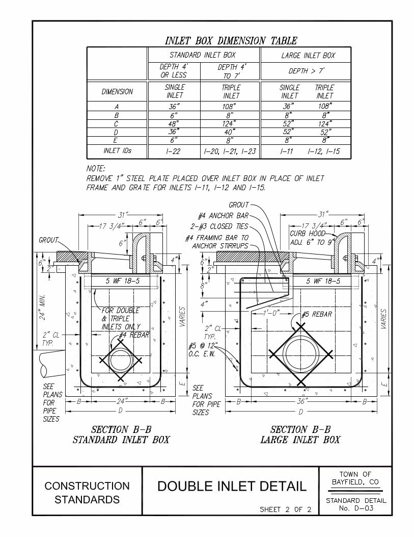
A. All concrete used in construction of manholes, inlet boxes, vaults, concrete encasement, thrust blocks, etc., shall be CDOT Class D. Unless otherwise specified, all concrete shall be made with Type II Portland Cement.
B. Cement mortar used in construction of manholes, inlets, vaults, etc., shall be mixed at a ratio of one part Portland cement to three parts sand. The amount of water used in the mortar shall be the minimum amount required for workability of the mix. Mortar shall be made with Type II Portland Cement unless otherwise specified. Mortar used for the patching of existing manholes shall be non-shrink type approved by the Town Engineer.
2.2 BACKFILL AND BEDDING MATERIAL
A. Bedding Classes: Herein are contained the various classes of Bedding:
1. Class A Bedding:
a. Class A bedding shall be defined as that method of bedding in which the lower half of the pipe is set in reinforced concrete (2000 psi min.). The minimum thickness of concrete under the lowest part of the conduit shall be ¼ of the outside pipe diameter but not less than 4 inches.
b. The trench shall be maintained free of water during placing of the concrete cushion before the concrete has taken its initial set. The concrete shall extend upward around the pipe to the spring line of the pipe barrel. The width of the concrete cradle shall be at least equal to the outside pipe diameter plus 8 inches.

Ordinance #345 12 Section 3 Revised November 6, 2012 General Utility Line Installation
2. Class B Bedding:
a. Class B bedding shall be defined as that method of bedding in which the pipe is set on compacted granular material. The trench shall be excavated to a depth below the established grade equal to ¼ of the outside pipe diameter, but not less than 6 inches. Compacted granular material shall be placed under the pipe and around the sides of the pipe up to the springline of the pipe barrel. The placing shall be done in a manner which will assure no separation or change in uniform gradation. The granular material shall be consolidated and compacted by hand operated mechanical vibrators to at least 90% of maximum dry density as determined by the modified proctor method ASTM D1557. Granular material shall be placed to one (1) foot above the top of the pipe.
3. Class C Bedding (Hand Shaped Bottom):
a. Class C bedding shall be defined as that method of bedding in which the pipe is placed on a native, stable soil foundation shaped to fit and uniformly support the lower quadrant of the pipe barrel for a width of at least 50% of the outside pipe diameter. Bell holes shall be excavated and kept free of foreign material.
b. The barrel of the pipe shall be bedded throughout its entire length. Native soil shall be hand compacted to springline and then placed to one foot above the top of the pipe and compacted to at least 90% maximum dry density. The remainder of the backfill shall be placed in compliance with the section on trench and excavation backfill.
B. Granular Bedding and Haunching Materials:
1 Granular materials required for bedding of pipe and structures, and haunching around pipe shall meet the following gradation requirements:
Total Passing by Sizes
Sieve Size (% by Weight) 3/4” 100 to 90 3/8” 20 to 55 No. 4 0 to 10 No. 8 0 to 5
2. The aggregate used shall contain not more than a total of 8% by weight of deleterious substances such as clay, shale or organic matter. The plasticity index shall not be over 6.
C. Stabilizing Material: In the event unstable trench conditions are found at pipe line grade, or in the case of over-excavation for rock, (dry) uniformly graded (class l, 4, or 5) rock shall be used for trench stabilization. Nothing in this bedding material classification is intended to preclude the use of sand bedding provided the sand has a plasticity index of 6 or less, when tested in accordance with ASTM D4318, and having no more than 15% passing 100 sieve.
D. Backfill Material:
1. In general, backfill shall be that material excavated from pipeline trenches on the site that is free from frozen materials, large amount of organic material, concrete, asphalt, dry clods, muck, debris and rock over three (3) inches in diameter. When, in the opinion of the Town of Bayfield, the excavated material is not satisfactory for use as backfill, suitable

Ordinance #345 13 Section 3 Revised November 6, 2012 General Utility Line Installation
backfill material shall be furnished by the Contractor and unsatisfactory material removed from the site.
2. Backfill material consisting of earth and rock shall contain a sufficient amount of earth to completely fill all voids between the rocks.
E. Special Backfill Material: Where required on the plans or when specified by the Town, backfill shall consist of a flowable fill meeting the requirements of CDOT structure backfill (flow-fill).
PART 3 EXECUTION
3.1 UTILITY INSTALLATIONS IN PUBLIC STREETS
A. Installation Requirements:
1. Arterial and Collector Streets: If a new or replacement utility is located in an existing arterial or collector street the installation shall be accomplished by boring and jacking, horizontal directional drilling, pipe bursting, pipe lining, or other trenchless techniques for installing or rehabilitating a utility, unless shown to be infeasible, in accordance with the Town’s ROW Work Ordinance and ROW permit conditions. Bored and jacked crossings shall encase the conduit or pipes in steel sleeves or casing pipe or other approved sleeve or casing pipe material. Open street cuts may be permitted where installations using trenchless technologies are shown to be infeasible to the satisfaction of the Public Works Director. The details of the open cut, including the backfill process and traffic control, shall be agreed to by the Public Works Director prior to commencement of the work.
2. Local Streets: If a new or replacement utility is located in an existing asphalt local street, the Public Works Director may permit open cuts of asphalt roads if conditions warrant. The details of the open cut, including the backfill process and traffic control, shall be agreed to by the Director prior to commencement of the work. If the conditions merit alternative means, as determined by the Public Works Director, the installation shall be accomplished by boring and jacking, horizontal directional drilling, pipe bursting, pipe lining, or other trenchless techniques for installing or rehabilitating a utility. Bored and jacked crossings shall encase the conduit or pipes in steel sleeves or casing pipe or other approved sleeve or casing pipe material.
3.2 TRENCH EXCAVATION
A. General: Following are the specifications that shall govern excavations and trenching for pipelines or other underground conduits and appurtenances for Town of Bayfield utilities. (See Standard Detail No. T-01.)
B. Responsibility:
1. The Contractor shall notify the Utility Notification Center of Colorado (UNCC), all utility companies and additional interested parties prior to commencement of work in order to insure that there will not be interruptions of services during construction. The Contractor shall notify all utility users in advance of any interruption to service. No interruption in service shall exceed 8 hours in duration. The Contractor shall be liable for all costs associated with repair to utilities due to excavation without following utility locate procedures. An excavation permit must be secured from the Town of Bayfield.

Ordinance #345 14 Section 3 Revised November 6, 2012 General Utility Line Installation
2. Should any utility be damaged in the construction operations, the Contractor shall immediately notify the owner of such utility. Unless authorized by the owner of the utility, the Contractor shall not attempt to make repairs.
3. In the event that during construction it is determined that any underground utility conduit or any aboveground utility will be encountered, the Contractor shall notify the affected utility company 48 hours in advance so that any anticipated problems can be addressed and utilities located.
C. Pavement Cuts, Surface Removals, and Topsoil Preservation:
1. The Contractor shall remove surface materials and obstructions only to the widths necessary for excavation of the trench. All fences, landscaping and structures not designated for removal shall be protected or, if moved, restored to their original condition after construction is complete.
2. No more than one-half of the width of a street shall have an open trench at any time.
3. Where excavation is required under paved areas, asphalt pavement shall be sawcut in a smooth, straight cut line with a vertical face a minimum of 12 inches beyond the trench wall and concrete pavement, curb and gutter, sidewalks, and concrete driveways shall be removed to the nearest construction or expansion joint. Where asphalt pavement is to be removed and curb and gutter must also be removed, the curb and gutter shall be removed to the nearest construction or expansion joint with the pavement removed to the joint. The equipment used for excavation must be equipped with pads for the stabilizers so as not to damage the street pavement. Front-end loader buckets should have a plank or buffer between the bucket and the street. If adjoining pavement, curb and gutter, or sidewalk is damaged during construction, the damaged improvements shall be removed by cutting back an additional distance to remove the damaged asphalt pavement or to the next joint for concrete structures.
4. All vegetation, concrete, asphalt and other refuse removed from the construction limits shall be separated from suitable topsoil and backfill material, and hauled to a disposal site secured by the Contractor.
5. Where the trench is in an unpaved area, clean topsoil suitable for final grading shall be stripped, stockpiled separately in approved locations, and restored to the surface after the trench is backfilled evenly. Where excavation is in a lawn covered area, the sod shall be cut and removed and replaced after trench filling so as to promote re-growth. Where sod is disturbed, the Contractor shall re-sod with like grass at the Contractor’s expense.
D. Stockpiling Excavated Material:
1. Excavated material shall be piled in locations that will not endanger the work, create traffic hazards or obstructed sidewalks and driveways. Fire hydrants, valve boxes, manholes and other utility access points shall be left unobstructed until the work is complete. Gutters and other water courses shall not be obstructed unless other provisions are made for runoff and street drainage.
2. All surplus material and excavated material unsuitable for backfilling shall be removed from the site and disposed of in areas secured by the Contractor.
E. Trenching Widths:

Ordinance #345 15 Section 3 Revised November 6, 2012 General Utility Line Installation
1. Trenches shall be excavated to the width necessary to permit the pipe to be laid and jointed properly and backfill materials placed and compacted as required. Where conduit is to be installed outside of existing pavement and pipes have an inside diameter of 33 inches or less, the trench shall be excavated at pipe level a minimum of 16 inches wider than the outside diameter of the pipe so that a clear space of not less than 8 inches is provided on each side of the pipe.
2. For pipes having an inside diameter of 36 inches or greater, the trench shall be excavated at pipe level a minimum of 24 inches wider than the outside diameter of the pipe so that a clear space of not less than 12 inches is provided on each side of the pipe. Wherever it is necessary to exceed these limits, approval of the Town of Bayfield shall be obtained and provision shall be made for the additional load imposed on the pipe. When sheeting is used, the widths indicated above shall be measured to the inside dimension between the sheeting.
F. Trenches with Sloping Sides: The banks of trenches shall be kept as nearly vertical as possible; however, where working conditions and easement or right-of-way permit (as determined by the Town of Bayfield), trenches may be excavated with sloping sides with the following limitations:
1. In traveled streets, alleys or narrow easements, only vertical trenches with proper bracing will be allowed.
2. Where trenches with sloping sides are permitted, the top width of the trench shall not exceed 8 feet and slopes shall not extend below a point 12 inches above the top of pipe. The trench shall be excavated with vertical sides below this point.
G. Trench Length:
1. No more than 200 feet of unbackfilled trench may be left open overnight. During the months of November through April, no uncovered trench shall be left overnight. Trenches should be backfilled as soon as possible to eliminate hazards and traffic congestion, but in no case shall the open trench length exceed 400 feet without the consent of the Town.
2. Trenches across existing streets are to be made so that traffic is not closed. Short duration closure may be allowed by the Town of Bayfield. In such instances, the Contractor shall notify the Town emergency services.
H. Tunneling: No tunneling under sidewalks, curb and gutter or other structures will be permitted, except when line can be pulled or jacked, in which case such line shall be left in place.
I. Bracing and Sheeting of Trenches:
1. All trenches shall be properly braced, sheeted or otherwise supported to provide safe working conditions and protection of the work and adjacent property.
2. Bracing and sheeting shall conform to the recommendations in the Occupational Safety and Health Standards for Construction (OSHA). A sand box or trench shield may be used in lieu of sheeting and bracing as permitted by OSHA. Unless otherwise approved, all trench support materials shall be removed in a manner that will prevent caving of the sides and movement or other damage to the pipe.
J. Excavation Below Design Grade: Where the excavation is carried beyond or below the lines and grades shown on the plans or staked, the Contractor shall, at the Contractor’s own expense, refill all such excavated space with suitable granular material.

Ordinance #345 16 Section 3 Revised November 6, 2012 General Utility Line Installation
K. Overexcavating for Rock:
1. When bedrock or boulders are encountered in the trench bottom, or loose, stony soil where there is the possibility of pipe being subjected to “point” contacts, the trench shall be overexcavated a minimum of six (6) inches. The overexcavated material shall be replaced with material approved by the Town Engineer and compacted.
2. If blasting is required for rock excavation, all work with explosives shall conform to Federal and State Laws, and OSHA rules and regulations. Any damage caused by blasting shall be repaired by the Contractor at the Contractor’s expense. Blasting is not permitted without written Town approval.
L. Unstable Trench Bottom: Where the trench bottom is found to consist of soft, spongy or unstable soil, frozen material, organic matter or any other material that the Town of Bayfield determines to be unsuitable for supporting the pipe, an additional depth equal to the outside diameter of the pipe shall be removed and replaced with suitable granular materials, properly compacted to provide adequate support.
M. Removal of Water: Trenches shall be kept free of water during pipe laying operations by draining, pumping or other approved methods. The water level shall be maintained below the trench bottom throughout the placement of trench cut-off walls, bedding, pipe laying, joining and backfilling operations. The dewatering shall be carried out so that it does not destroy or weaken the strength of the soil under or alongside the trench. Water shall be disposed of in a suitable manner without damage to adjacent property or without being a menace to public health and convenience. Under no circumstances shall trench water be discharged into sanitary sewers. The method of disposal of trench water shall be approved by the Town. A construction dewatering permit shall be obtained by the contractor, as required by the Colorado Water Quality Control Division.
N. Trench Cut-Off Walls: Trench cut-off walls shall be installed in utility trenches when free water is present or there is evidence that the ground water table seasonally rises above the floor of the trench. Trench cut-off walls, constructed of clay material, shall be constructed at 100-foot intervals along the trench to prevent ground water migration in the trench. The cut-off walls shall be a minimum of 1 foot thick, extend 18 inches above the top of the pipe, and be keyed 6 inches, minimum, into undisturbed soils of the trench bottom and sides.
O. Preparing the Trench Bottom: If soil conditions are stable, and the trench bottom is of a material that can be cut true and straight, pipe can be installed using the uniform trench bottom for support. The trench bottom must be straight, free of bumps or hollows, and at the correct grade. As the pipe is laid, any irregularities in the trench bottom must be leveled off or filled in with tamped soil. The trench bottom may also be prepared by digging at least 4 inches deeper than pipe grade and then bringing the trench bottom up to grade with selected refill material tamped to provide the proper cushion for the pipe. A coupling or bell hole shall be dug at each pipe joint so that the pipe is uniformly supported along its length. The hole shall have sufficient length, width and depth to permit assembly of the joint and provide a minimum clearance of two (2) inches between the coupling and the trench bottom (See Standard Detail No. T-01).
3.3 BACKFILLING
A. Backfilling of utility trenches shall be with flowable fill in the case of arterial or collector street crossings or approved aggregate materials for local street crossings, unless otherwise approved, as specified in the Town ROW permit. When conditions do not allow quick set to flowable fill

Ordinance #345 17 Section 3 Revised November 6, 2012 General Utility Line Installation
or backfill of a utility trench is delayed, steel traffic plates may be required to allow traffic passage. The determination of the necessity of traffic plates shall be in accordance with the Town’s ROW permit requirements or by the Public Works Director in the event of unforeseen conditions.
B. Compacting Backfill Material: Backfill material in trenches shall be compacted to at least ninety (90%) percent of maximum density except for the top three (3) feet of the trench under existing or proposed roads which shall be compacted to at least ninety-five (95%) percent of maximum density. Maximum density shall be as determined by the modified proctor method ASTM D1557. All approved backfill material shall be adjusted to within three (3) percent of the optimum moisture content prior to its placement in the trench. When sand is placed as backfill it must have a minimum moisture content of 5%.
C. Initial Bedding and Backfilling:
1. Backfilling should follow pipe assembly as closely as possible. During initial bedding and backfilling, the Contractor shall take all necessary precautions to prevent movement or distortion of the pipe or structure being backfilled. Firm, continuous support for the pipeline shall be accomplished by tamping the soil solidly under the pipe and couplings. Bedding material shall be placed equally along both sides of the pipe and provide effective support of the pipe in the haunching area. This is accomplished by placing bedding material equally along both sides of the pipe and thoroughly compacting it by hand under the haunches and around the pipe. Tamping should be done in 4-inch layers. Side support is accomplished by tamping the soil firmly under the haunches of the pipe to the springline and compacting it out to the undisturbed trench walls.
2. Backfilling of the trench with bedding material shall continue to a point that is at least one foot above the top of the pipe. The balance of the backfill may be machine placed in lifts not to exceed 6 inches. Compaction between lifts is required by mechanical or other approved means. Trenches outside of proposed roads shall be backfilled in lifts not to exceed 24 inches and provide mounding between 6 inches and 12 inches over existing natural ground.
3. Flooding or jetting of trenches shall not be permitted.
E. Testing: All backfill shall be frequently tested to insure that the required density is being attained. The minimum requirements for compaction testing shall be as follows:
1. For every 300 linear feet of trench and each branch or section of trench less than 300 feet in length, at least one compaction test shall be performed every other lift of backfill. Service line trenches shall be tested randomly at a rate of 1 out of every 3 service connections. Compaction tests shall be taken at random locations along the trench and wherever poor compaction is suspected by the Town of Bayfield representative. If any portion of the backfill placed fails to meet the minimum density specified, the area shall be defined by additional tests if necessary and the material in the designated area shall be removed and replaced to the required density at the Contractor’s expense.
2. All compaction testing shall be performed by a materials testing company hired by the Town; costs of testing will be invoiced to the Contractor. It shall be the Contractor’s responsibility to coordinate with the testing company in order to accommodate the required testing.

Ordinance #345 18 Section 3 Revised November 6, 2012 General Utility Line Installation
3. Approval of all test results are required as a basis of acceptance of facilities by the Town of Bayfield.
3.4 RESTORATION
A. Restoration of Grounds:
1. The cleanup and restoration of grounds shall be a continuous process from the beginning of construction to final completion of the work. The Contractor shall keep the work site free from the accumulation of debris and waste material caused by the Contractor’s operation.
2. Immediately after the pipeline is backfilled, the area shall be cleaned and restored to the original grade and condition. All fences shall be replaced to the same elevation and alignment and restored to a condition equal to or better than that at the beginning of construction.
B. Restoration of Paved and Concrete Surfaces: Immediately after any section of a completed utility has been tested and accepted by the Town, the Contractor shall replace all paved surfaces removed or damaged by the Contractor’s operation unless an alternative patching schedule is approved by the Town in writing. All asphalt pavement removed shall be replaced with hot mixed bituminous pavement. Paved surfaces shall be restored to their original line and grade and finished to match adjacent undisturbed surfaces. The excavation Contractor shall be responsible for the maintenance of the patch for a period of one (1) year or until it is removed and replaced by the Town of Bayfield or their Contractor.
1. Asphalt pavement patches shall consist of 4 inches of asphalt pavement or the existing pavement thickness, whichever is greater, over flowable fill or compacted base course, as required by the Town’s ROW permit. Tack coat shall be applied to all adjoining asphalt and concrete surfaces prior to patching. Lifts shall not exceed 3 inches in thickness and the asphalt compacted in accordance with the requirements of Section 7. Sawcuts that extend beyond the patch shall be sealed.
2. Concrete pavement patches shall be full panel replacement with the replacement panel doweled to adjoining panels with ¾” by 18 inch epoxy-coated steel reinforcing bars on 12-inch centers. Portland cement concrete shall be placed to a thickness of 6 inches or the thickness of the removed pavement, whichever is greater.
END OF SECTION

Ordinance #345 19 Section 4 Revised November 6, 2012 Water Distribution Systems
SECTION 4
WATER DISTRIBUTION SYSTEMS
PART 1 GENERAL
1.1 SUMMARY
A. Related Sections
1. Section 2 – Site Preparation and Earthwork
2. Section 3 – General Utility Line Installation
1.2 APPLICABLE STANDARDS
A. American Association of State Highway Transportation Officials (AASHTO)
1. Manual on Uniform Traffic Control Devices (MUTCD)
B. American Society for Testing and Materials (ASTM).
1. ASTM B88 – Standard Specification for Seamless Copper Water Tube
2. ASTM B251 – Standard Specification for General Requirements for Wrought Seamless Copper and Copper-Alloy Tube
3. ASTM D3139 – Standard Specification for Joints for Plastic Pressure Pipes Using Flexible Elastomeric Seals
4. ASTM F477 – Standard Specification for Elastomeric Seals (Gaskets) for Joining Plastic Pipe
5. ASTM F876 – Standard Specification for Crosslinked Polyethylene (PEX) Tubing
C. American Water Works Association (AWWA) (with corresponding American National Standards Institute (ANSI) reference standard, where applicable)
1. ANSI/AWWA C104/A21.4 – Cement-Mortar Lining for Ductile-Iron Pipe and Fittings
2. ANSI/AWWA C111/A21.11 – Rubber-Gasket Joints for Ductile-Iron Pressure Pipe and Fittings
3. ANSI/AWWA C151/A21.51 – Ductile-Iron Pipe, Centrifugally Cast
4. ANSI/AWWA C153/A21.53 – Ductile-Iron Compact Fittings for Water Service
5. AWWA C500 – Metal-Seated Gate Valves for Water Supply Service
6. AWWA C502 – Dry-Barrel Fire Hydrants
7. AWWA C504 – Rubber-Seated Butterfly Valves
8. AWWA C509 – Resilient-Seated Gate Valves for Water Supply Service
9. AWWA C600 – Installation of Ductile-Iron Water Mains and Their Appurtenances

Ordinance #345 20 Section 4 Revised November 6, 2012 Water Distribution Systems
10. AWWA C605 – Underground Installation of Polyvinyl Chloride (PVC) Pressure Pipe and Fittings for Water
11. AWWA C651 – Disinfecting Water Mains
12. AWWA C800 – Underground Service Line Valves and Fittings
13. AWWA C900 – Polyvinyl Chloride (PVC) Pressure Pipe and Fabricated Fittings, 4 In. Through 12 In. (100 mm Through 300 mm), for Water Transmission and Distribution
14. AWWA C905 – Polyvinyl Chloride (PVC) Pressure Pipe and Fabricated Fittings, 14 In. Through 48 In. (350 mm Through 1,200 mm), for Water Transmission and Distribution
D. Colorado Department of Transportation (CDOT)
1. Standard Specifications for Road and Bridge Construction
PART 2 PRODUCTS
2.1 PIPE AND FITTINGS FOR WATER MAINS
A. General:
1. Pipe for water mains shall be AWWA C900 or C905 PVC pipe, unless otherwise approved by the Town Engineer or Director of Public Works. Service pipe shall be Type K copper tubing, only, between the water main and the water meter, and Type K copper tubing or cross-linked polyethylene (PEX) tubing between the water meter and the building.
B. AWWA C900 PVC Pipe:
1. PVC pipe used for 4-inch through 12-inch water mains shall meet the requirements of AWWA C900 and shall be Pressure Class 305 DR-14, minimum. All pipe used for drinking water shall be blue in color.
2. Joints shall be integral bell and spigot type conforming to ASTM D3139, sealed with an elastomeric gasket conforming to ASTM F477 for high head conditions (50 ft of head or higher). The bell section shall be at least as strong as the pipe wall.
B. AWWA C905 PVC Pipe:
1. PVC pipe used for water mains 14 inches in diameter and larger shall meet the requirements of AWWA C905 and shall be DR-14, minimum, with a pressure rating of 305 pounds per square inch. All pipe used for drinking water shall be blue in color.
2. Joints shall be integral bell and spigot type conforming to ASTM D3139, sealed with an elastomeric gasket conforming to ASTM F477 for high head (50 ft of head or higher). The bell section shall be at least as strong as the pipe wall.
C. Ductile Iron Pipe:
1. Ductile iron pipe for water mains shall conform to ANSI/AWWA C151/A21.51 and shall be Special Thickness Class 52. Ductile iron pipe shall feature an asphaltic exterior coating meeting the requirements of ANSI/AWWA C151/A21.51 and a cement-mortar lining meeting the requirements of ANSI/AWWA C104/A21.4, unless otherwise approved by the Town.

Ordinance #345 21 Section 4 Revised November 6, 2012 Water Distribution Systems
2. Joints shall be mechanical or push on joints conforming to ANSI/AWWA C111/A21.11. Gaskets shall be of synthetic rubber material meeting the requirements of ANSI/AWWA C151/A21.51.
D. Fittings:
1. Fittings for PVC and ductile iron pipe shall be compact ductile iron fittings, conforming to ANSI/AWWA C153/A21.53. Joints shall be mechanical joints with rubber gaskets meeting the requirements of ANSI/AWWA C111/A21.11. Unless otherwise approved by the Town, fittings shall feature an asphaltic exterior coating meeting the requirements of ANSI/AWWA C153/A21.53 and a cement-mortar lining meeting the requirements of ANSI/AWWA C104/A21.4.
E. Manufactured Joint Restraints:
1. Manufactured joint restraints for pipe fittings shall be EBAA Iron, Megalug®, of a type appropriate for the pipe material, or equal, as approved by the Town.
F. Copper Service Pipe:
1. Copper tube for water service lines shall be type K, soft temper for underground service conforming to ASTM B88 and B251. The pipe shall be marked with the manufacturer’s name or trademark and a mark indicating the type of pipe. The outside diameter of the pipe and minimum weight per foot shall not be less than that listed in ASTM B251, Table 11.
G. PEX Service Pipe:
1. Cross-linked polyethylene (PEX) tubing shall conform to ASTM F876, as manufactured by Uponor, Inc., under the tradenames Wirsbo AQUAPEX tubing and ProPEX fittings, or approved equal.
2.2 APPURTENANCES FOR WATER DISTRIBUTION
A. Fire Hydrants:
1. Fire hydrants shall be the post type dry barrel type and shall conform to the requirements of AWWA C502. Hydrants shall be Mueller Super Centurion A-423. No substitutes will be accepted.
2. The standard hydrant shall have a six-inch mechanical joint inlet connection, a 5-¼ inch main valve opening three way: one 5-inch Storz pumper connection and two 2-1/2 inch hose nozzles (National Standard Hose Thread).
3. Hydrants shall feature a “breakaway” flange and operating stem that helps prevent damage to the barrel sections upon impact.
4. The hydrant barrel shall feature a “bury” rib to indicate the design finished grade level for proper installation of the hydrant. The “bury” rib shall be located so that the “breakaway” flange is installed 2 to 6 inches above finished grade and the centerline of the hydrant nozzles are installed 18 inches above finished grade.
5. The operating nut and nozzle cap wrench nuts shall be 1-1/2 inches pentagon, measuring from point to opposite flat side at the base and tapering uniformly to 1-7/16 inches at the top. The height of the nut shall not be less than one inch.

Ordinance #345 22 Section 4 Revised November 6, 2012 Water Distribution Systems
6. The nozzle caps shall be removable and the operating nut opened by turning to the left (counter-clockwise). Nozzle caps shall be securely chained to the upper barrel section.
7. Fire hydrants shall be painted with an approved fire hydrant red Alkyd Enamel.
8. All fire hydrants shall feature a high visibility marker, of the type approved by the Town at the time of hydrant installation.
C. Gate Valves:
1. Shut-off valves less than 16 inches in size shall be gate valves.
2. The minimum requirements for all gate valves shall conform to the standards of ANSI/AWWA C500 or AWWA C509.
3. All gate valves shall be resilient wedge, cast or ductile iron body, fully bronze mounted with non-rising stem and parallel seats. The stem and all wearing surfaces shall be bronze or other approved non-corrosive material. Contact surfaces shall be machine finished and all wearing surfaces shall be easily renewable. Nonferrous bushings shall be of substantial thickness tightly fitted and pressed into machined seats. A clockwise turn of the stem shall close the valve. Acceptable brands of gate valves are Watrous, Mueller, and Dresser.
4. End Connections: End connections of gate valves shall consist of mechanical or push-on (rubber gasket) joints conforming to ANSI/AWWA C111/A21.11.
5. Wrench Nuts: Wrench nuts shall be made of cast iron and shall be 1-5/16 inches square at the top, 2 inches square at the base, and 1-3/4 inches high.
D. Butterfly Valves:
1. Shut-off valves 16 inches or larger in size shall be butterfly valves.
2. Butterfly valves shall conform to AWWA C504 specifications. Valves shall be manufactured by Henry Pratt Co, or an approved equal. All valves shall be 200 psi working pressure with direct buried operators. Provision shall be made for locking the disc in the fully open or fully closed position. Counter clockwise turn of the operating nut shall open the valve.
E. Valve Boxes: A cast iron valve box and lid, designed for H-20 traffic loading, shall be provided for each underground valve. Valve boxes shall be 5-½ inches diameter, adjustable screw-together type, sized for the type of valve and depth of bury. The lid shall have the word “WATER” permanently cast in the top.
F. Air and Vacuum Valves: Air and vacuum valves shall be of the type and size specified. They shall be designed for 200 psi working pressure and shall be Val-matic or CLA-VAL Type RN or approved equal. A separate isolation valve of the same size and pressure rating as the air valve shall be installed between the water main and the air and vacuum valve. The air and vacuum valve shall be housed in a vault made of reinforced concrete pipe or manhole riser section. The vault shall be covered with a precast concrete lid and cast iron manhole ring. The vault shall be insulated in a manner acceptable to the Town Engineer.
G. Tracer Wire and Caution Tape: Tracer wire shall be 10-gauge solid copper or equivalent strength copper clad steel tracer wire with blue jacket, manufactured for direct bury. Caution tape shall be 6 inches wide, blue in color, and have “WATER” printed on the tape.
H. Steel Casing:

Ordinance #345 23 Section 4 Revised November 6, 2012 Water Distribution Systems
1. Steel casing for horizontally bored installations or for future water line installations shall be standard wall thickness, minimum.
I. Casing Spacers:
1. Casing spacers for water line installations shall be stainless steel or non-metallic manufactured casing spacers, as approved by the Town.
J. Service Line Appurtenances:
1. Service saddles shall be as approved by the Town of Bayfield.
2. Corporation stops shall be brass ball valves with AWWA taper thread inlet and compression connection for copper tubing outlet, Mueller B-25008, or approved equal.
3. Curb stops shall be brass ball valves with inlet and outlet compression connections for copper tubing, Mueller Ball Curb B-25209-R, or approved equal.
4. Curb stop boxes shall be two piece cast iron extension type with arch pattern base with spring loaded telescoping upper section and one-piece cast iron lid with spanner wrench holes, Mueller H-10314, H-10310, or approved equal.
5. The meter pit, meter yoke, meter, radio transceiver, all fittings required for the meter installation shall be purchased from the Town of Bayfield.
K. Flexible Couplers: Flexible couplings shall have cast iron or steel sleeves the same as pipe type furnished; ductile iron flanges, bronze bolts and nuts; and wedge-type rubber gaskets. The couplings shall be designed for a 200 psi working pressure except as noted and each shall be sized to properly fit the ends of the two pieces of pipe being joined. The couplings shall be Smith-Blair Type 433, Baker Series 236 Cast Transition Couplings, or equal approved by the Town.
PART 3 EXECUTION
3.1 INSTALLATION OF WATER LINES, FORCE MAINS, SIPHONS AND OTHER PRESSURE PIPELINES
A. Installation of Pipe and Appurtenances: All pipes, valves, hydrants, manholes and other pipeline appurtenances shall be installed and tested in accordance with the construction plans and specifications, Sections 2 and 3 of these Construction Specifications, applicable AWWA and ASTM Standards and Manufacturer’s instructions. When installation requirements or procedures differ, the Town of Bayfield will determine which will take precedence over the others.
B. Pipe Laying:
1. Pipe shall be laid on the alignment shown on the plans, unless otherwise approved by the Town. All pressure pipelines shall be laid at a minimum depth of 48 inches measured from the proposed final ground surface or of the proposed road surface to the top of the pipe, unless otherwise approved by the Town of Bayfield.
2. The inside of the pipe and jointing surfaces shall be kept clean and free from mud, dirt, gravel, ground water and other foreign material. When pipe laying is not in progress, the

Ordinance #345 24 Section 4 Revised November 6, 2012 Water Distribution Systems
open ends of the pipeline shall be kept closed with water-tight plugs. All pipe lengths shall be squarely cut.
3. Long radius horizontal or vertical curves for C900 PVC pipe may be laid by deflecting the pipe through longitudinal bending of the pipe body. Maximum allowable bending shall be per the Manufacturer’s recommendations and AWWA C605 limits. Deflection at the pipe joints for C900 PVC pipe is not allowed. Long radius horizontal or vertical curves for C905 PVC pipe or ductile iron pipe shall be achieved through deflections at the pipe joints in accordance with the Manufacturer’s recommendations, and AWWA C600 for ductile iron pipe.
4. Tracer wire shall be taped to the top of PVC water pipe along the length of the pipe. At each water service and valve box, a splice along the main tracer wire shall be made with a 3M water-proof wire nut and a pig tail shall be extended to the top of the valve box and fire hydrant to provide a ready connection for tracing. Continuity shall be checked at all surface connections to ensure proper connections throughout the system. Caution tape shall be installed 12 inches above the entire length of all piping, including mains and services. At utility crossing points, warning tape shall be above each applicable line a distance of 9 inches, minimum, and below the overlaying utility line crossing by nine inches minimum
5. Horizontal boring and jacking may be required for pipeline crossings of major Town streets, CDOT highways, and La Plata County roads. Pipelines shall be installed in steel casing pipe using manufactured casing spacers. The casing pipe diameter and the height of the casing spacer risers and runners shall provide a minimum of ½ inch clearance between the casing pipe and the extreme outside diameter of the carrier pipe joint. The spacing and location of casing spacers along pipe sections shall be in accordance with manufacturer’s recommendations. Rubber end seals, secured with stainless steel clamps, shall be installed at the ends of the casing pipe.
C. Joint Restraint:
1. All joints requiring restraint, including pipe bends, tees, caps, valves, hydrants and other locations shown on the plans, shall be installed with both manufactured joint restraints and concrete thrust blocks.
2. Manufactured joint restraints shall be installed in accordance with Manufacturer’s requirements and the length of pipe restrained beyond the fitting shall consider the soil type, pipe pressure, pipe diameter, and other factors, in accordance with the joint restraint manufacturer’s recommendations.
3. The size and location of thrust blocks shall be as shown on the plans or in accordance with Standard Detail No. W-06. Thrust blocks shall be poured on firm, stable foundation material and all bearing surfaces shall be against undisturbed earth. Concrete for thrust blocks shall be CDOT Class B. Unless otherwise specified, all concrete shall be made with type II Portland Cement. Reinforcing steel and bolts used to anchor valves, fittings, etc., to thrust blocks shall meet tensile requirement of ASTM Grade 40. All anchorage steel not embedded in concrete shall be coated with coal tar or other approved coating material.
D. Installation of Valves and Valve Boxes:
1. Shut-off valve spacing shall be a maximum of 400 feet.

Ordinance #345 25 Section 4 Revised November 6, 2012 Water Distribution Systems
2. All tees and crosses shall have a valve installed on each branch, unless otherwise approved by the Public Works Director.
3. Each valve shall be installed in a vertical position and anchored to a concrete support block as shown on the Standard Detail Nos. W-02 and W-03.
4. An adjustable screw type valve box shall be set into position during backfilling operations. The lower section of the valve box shall be cushioned with backfill material so that it does not rest directly upon the body of the valves or upon the water main. The upper section of the unit shall be placed in proper alignment and adjusted so that its top will be at final grade. The lid for valve boxes within paved areas shall be set ¼ inch below the adjacent pavement grade; valve boxes set outside of paving shall be set 3 inches above the adjacent finished grade. The completed valve box shall be vertically centered over the valve operating nut and each valve shall be tested for proper access and operation.
5. Concrete collars are required around all valves placed within paved areas and shall be constructed in accordance with Standard Detail No. W-04.
E. Installation of Fire Hydrants:
1. Hydrants shall be installed at the locations shown on the plans. Hydrants shall be connected to the main with a 6-inch diameter branch controlled by 6-inch gate valve adjacent to the main line to allow replacement of the fire hydrant.
2. Hydrants shall be plumb and set so that the center of the pumper nozzle is no less than 18 inches above finished grade. The nozzles shall be parallel with or at right angles to the curb, with the pumper nozzle facing the curb.
3. Hydrants shall be protected if subject to mechanical damage. The means of protection shall be arranged in a manner that will not interfere with the connection to, or operation of, hydrants.
4. A minimum of l/4 cubic yard of washed gravel shall be placed around the base of the hydrant to insure proper drainage of the hydrant after use. Hydrants shall be restrained in accordance with Section 3.1.C. Weep holes which drain the hydrant shall not be covered with concrete (See Standard Detail No. W-01).
F. Installation of Water Services:
1. Each water service line shall be machine tapped and connected to the water main through a brass corporation stop. The main shall be tapped at an angle of forty-five degrees (45°) from the vertical, and the stop must be turned so that the T-handle will be on top (See Standard Detail No. W-05).
2. Underground water service pipe shall be laid not less than 5 feet horizontally from the building sewer service line. Water service lines shall be placed at a minimum depth of 42 inches.
3. Residential water service lines shall be ¾ inches in diameter; commercial water service lines shall be a minimum of 1 inch in diameter. Commercial water service lines shall be sized based on the number of fixture units.
4. In new developments and subdivisions where curb and gutter will be installed, a 2-inch “W” shall be stamped in the curb where the water service line crosses under the curb. For

Ordinance #345 26 Section 4 Revised November 6, 2012 Water Distribution Systems
testing and disinfection of water service lines, tapping or shut-off valves shall be installed at the end of the line with the valve set in the “OFF” position.
5. Curb stop and meter installation shall be as follows:
a. Where the sidewalk is attached to the curb or detached less than 4 feet from the curb, the curb stop shall be a minimum of 1 foot and a maximum of 2 feet from the back of the sidewalk. Where the sidewalk is detached a minimum of 4 feet from the curb, the curb stop shall be a minimum of 1 foot and a maximum of 2 feet from the back of the curb. The meter pit shall be a minimum of 1 foot and a maximum of 3 feet from the curb stop.
b. The curb box and meter pit shall be plumb when backfilled and the curb box lid and the meter pit lid shall be a minimum of 2 inches and a maximum of 4 inches above the final grade. Landscaping or backfill shall not obscure the curb stop or meter pit.
c. The meter and meter yoke must be no less than 4 inches and no more than 12 inches below the top of the meter pit housing.
d. Curb stop and meter installation shall be as shown in Standard Detail W-05.
6. Water service lines from the water main to the water meter shall be type K copper tubing. Water service lines connecting the water meter to the residence or business shall be type K copper tubing for a minimum of 3 feet beyond the meter pit, with the remainder of the service line being either type K copper tubing or PEX tubing. Tracer wire shall extend along each service line and terminate in the meter pit, as shown in Standard Detail W-05.
G. Connection to Existing Mains:
1. New water main lines shall be connected to existing mains in service with a tapping valve or shutoff valve. The valve will remain closed until the new lines have been tested, disinfected with at least 50 ppm residual of chlorine for 24 hours. Chlorination of the lines shall be performed in accordance with AWWA C651.
2. Where the connection of the new work to old requires interruption of service, the Public Works Director and the Contractor shall mutually agree upon a date and time for connections which will allow ample time to assemble labor and materials. The Contractor or Developer will be responsible for all tie-ins for new development.
3.2 HYDROSTATIC TESTING OF PIPELINES
A. Water mains, force mains, siphons, and all other pipelines that will operate under pressure shall be hydrostatically tested in accordance with these specifications and AWWA C605 for PVC pipe and AWWA C600 for ductile iron pipe.
B. The Contractor shall furnish all labor, equipment, tools, water and other incidental items required to conduct the tests. Test results will not be considered valid without the presence of the Town’s inspector throughout the test.
C. No pressure testing shall be performed until all thrust blocks have been placed and cured for at least two (2) days, and the pipeline backfilled adequately to prevent any movement or lifting of the pipe. Pavement or other permanent surfaces shall not be placed until all pressure and leakage tests are satisfactorily completed.
D. Test Pressure: Unless otherwise specified, the test pressure for all pipes shall not be less than 1.25 times the maximum anticipated sustained working pressure at the highest point along the

Ordinance #345 27 Section 4 Revised November 6, 2012 Water Distribution Systems
test section unless the pressure exceeds the design pressure limit for any pipe, thrust restraint, valve fitting, or other appurtenance of the test section, except that the minimum test pressure for water distribution lines shall be 150 psi.
E. Filling: The pipeline shall be filled with potable water at least twenty-four (24) hours before being subjected to the hydrostatic pressure test. Each section of pipeline shall be filled slowly and all air expelled by means of taps at points of highest elevation. Tapping to remove air shall be the responsibility of the Contractor and location of taps shall be approved by the Town Inspector.
F. Procedure:
1. The duration of the hydrostatic test shall be 2 hours.
2. The specified test pressure shall be applied by means of a pump connected to the pipe in a manner satisfactory to the Town’s Inspector. The pump shall be used to maintain a pressure within 5 psi of the specified hydrostatic test pressure. No pipe installation will be accepted if the quantity of makeup water for the section of line being tested is more than that determined by the following equation:
where: C = quantity of makeup water, gallons per hour
L = length of pipe section being tested, feet D = nominal diameter of pipe, inches P = average test pressure, psi gauge
3.3 DISINFECTION OF WATER LINES
A. After completion of pressure and leakage testing and prior to being placed into service, all new water mains and repaired portions of or extensions of existing mains shall be chlorinated by the Contractor in accordance with AWWA Standard C651.
B. Preventing Reverse Flow: Valves shall be manipulated so that the strong chlorine solution in the line being treated will not flow back into the line supplying the water.
C. Chlorinating Valves and Hydrants: In the process of chlorinating newly laid pipe, all valves or other appurtenances shall be operated while the pipeline is filled with the chlorinating agent and under normal operating pressure.
D. Final Flushing and Testing: Following chlorination, all treated water shall be thoroughly flushed from the newly laid pipe at its extremity until the replacement water throughout its length shows upon test a chlorine residual of less than 2 mg/l. Chlorinated water discharged to sensitive environments shall be neutralized prior to discharge, in accordance with applicable Federal or State requirements.
E. Bacteriological Testing: Following flushing two sets of samples, taken at least 24 hours apart, shall be collected by the Contractor for testing for bacteriological quality under the supervision of the Town. Each l,200 linear feet of water main, plus each end and each branch, shall be sampled and tested and results of the test supplied to the Town before acceptance of any portions of the line.
000,148PLDC =
Ordinance #345 28 Section 4 Revised November 6, 2012 Water Distribution Systems
3.4 FINAL INSPECTION AND ACCEPTANCE
A. The acceptance of all pipelines by the Town will be based on the following:
1. Submittal of satisfactory results of required tests (such as hydrostatic pressure test, compaction, bacteriological tests, etc.) certified by the Town Public Works Department or an approved independent laboratory, as appropriate.
2. Passing a final inspection of the work by the Town.
3. Submittal of Record Drawings meeting the requirements of Section 1, Article 1.3.
END OF SECTION
Ordinance #345 29 Section 5 Revised November 6, 2012 Sanitary Sewer Collection Systems
SECTION 5
SANITARY SEWER COLLECTION SYSTEMS
PART 1 GENERAL
1.1 SUMMARY
A. Related Sections
1. Section 3 – General Utility Line Installation
2. Section 4 – Water Distribution Systems
1.2 QUALITY STANDARDS
A. American Association of State Highway and Transportation Officials (AASHTO)
1. AASHTO M 199: Precast Reinforced Concrete Manhole Sections
B. American Society for Testing and Materials (ASTM)
1. ASTM A48: Standard Specification for Gray Iron Castings
2. ASTM C478: Standard Specification for Precast Reinforced Concrete Manhole Sections
3. ASTM F1417 – Standard Test Method for Installation Acceptance of Plastic Gravity Sewer Lines Using Low-Pressure Air
C. American National Standards Institute (ANSI)/American Water Works Association (AWWA)
1. ANSI/AWWA C153/A21.53-11: AWWA Standard for Ductile-Iron Compact Fittings
2. ANSI/AWWA C901: AWWA Standard for Polyethylene (PE) Pressure Pipe and Tubing, ½ In. (13 mm) through 3 In. (76 mm), for Water Service
3. ANSI/AWWA C906: AWWA Standard for Polyethylene (PE) Pressure Pipe and Fittings, 4 In. Through 65 In. (100 mm Through 1,600 mm), for Waterworks
PART 2 PRODUCTS
2.1 PIPE AND FITTINGS FOR SANITARY SEWER CONSTRUCTION
A. General:
1. Pipe used in construction of gravity sanitary sewer mains and service lines shall be polyvinyl chloride (PVC). The minimum pipe size for gravity sewers shall be eight (8) inch diameter for mains and laterals, and four (4) inch diameter for service lines. The minimum wall thickness for PVC pipe shall conform to Standard Dimension Ratio (SDR) 35.
Ordinance #345 30 Section 5 Revised November 6, 2012 Sanitary Sewer Collection Systems
2. Sanitary sewers under pressure shall be of AWWA C900 PVC, or high density polyethylene (HDPE), AWWA C906.
B. PVC Gravity Sewer Pipe:
1. PVC gravity sewer pipe up to and including fifteen (15) inch diameter pipe shall conform to ASTM D3034. PVC pipe eighteen (18) inches and greater in diameter shall conform to the requirements of ASTM F769. The minimum wall thickness for PVC pipe shall be SDR 35.
2. Joints: PVC gravity sewer pipe shall have integral bell and spigot joints. PVC sewer pipe shall be connected with flexible elastomeric seals per ASTM D3212. Gaskets shall be neoprene or other synthetic rubber material conforming to ASTM F477. Rubber gaskets for compression type joints for PVC pipe and fittings shall conform to the requirements of ASTM F477.
3. Fittings: All fittings for PVC gravity sewer pipe shall conform to ASTM D3034, Type PSM. Wyes for 4-inch or 6-inch service connections to sewer mains shall be saddle-type fittings made of PVC plastic with an “O” ring between the main and saddle. The saddle shall be secured to the main line with two stainless steel bands.
C. PVC Pressure Pipe:
1. PVC pipe used for sanitary sewers under pressure shall meet the requirements of AWWA C900 and shall be Class 200, minimum.
2. Joints: Joints shall be bell and spigot type sealed with an elastomeric gasket conforming to ASTM D3139 and F477. The bell section shall be at least as strong as the pipe wall.
3. Fittings: Fittings for PVC pressure pipe shall be of cast iron or ductile iron and shall be cement lined per AWWA C104. Ductile iron pipe fittings shall be in accordance with AWWA C153 and shall have a pressure rating of not less than that specified for the pipe. All fittings shall be restrained with mechanical joint restraints, EBAA Iron Megalug®, or approved equal. The length of pipe restrained beyond the fitting shall consider the soil type, pipe pressure, pipe diameter, and other factors, in accordance with the joint restraint manufacturer’s recommendations.
D. HDPE Pressure Pipe:
1. HDPE pipe used for sanitary sewers under pressure shall meet the requirements of AWWA C901 and ASTM D3035 for sizes up to 3-inch IPS diameter, AWWA C906 and ASTM F714 for sizes 4-inch IPS diameter and above, DR 26.
2. Joints: Joints shall be formed through the butt fusion process in accordance with ASTM F2620.
3. Fittings: Molded fittings shall be in accordance with ASTM D3261.
2.2 MANHOLES FOR SANITARY SEWERS
A. General: Manholes shall be constructed in accordance with Standard Detail Nos. S-01 through S-04. Concrete collars are required around all manholes placed within paved areas and shall be constructed in accordance with Standard Detail No. S-05. Manholes set in untraveled areas shall be set so that the cover is 3 to 6 inches above the surrounding ground.

Ordinance #345 31 Section 5 Revised November 6, 2012 Sanitary Sewer Collection Systems
B. Cement: All cement used in mortar, concrete bases, and precast manhole riser sections, cones and flat tops, for sanitary sewer manholes, shall be Type V or modified Type II Portland cement having less than five (5) percent tricalcium aluminate. Type II Portland cement may be used in the various concrete elements of storm sewer manholes.
C. Precast Concrete Manhole Sections:
1. Manhole risers, cones, flat tops, manhole bases and grade rings shall be precast reinforced concrete sections conforming to ASTM C478. The minimum inside diameter shall be 4 feet. Manholes which are 5 feet or less in depth as measured from the invert to the top of rim shall have a flat reinforced concrete top, unless otherwise approved. Manholes greater than 5 feet deep as measured from the invert to the top of rim shall use an eccentric conical top section. The use of a cast-in-place manhole base requires written approval of the Town.
2. Manhole bases, risers, and conical sections shall be made with tongue and groove ends for continuous and uniform joints between sections. Such joints shall be sealed with approved butyl rubber sealant or other approved flexible joint sealant.
3. Manhole barrel sections shall be provided with manhole steps as specified or called for on the details. Steps shall be equally spaced, with the first step being placed a maximum of 24 inches from the top of the manhole ring.
D. Manhole Steps:
1. Manhole steps shall be steel reinforced plastic, with 3/8-inch diameter reinforcing. Plastic shall be copolymer polypropylene meeting requirements of ASTM D4101, Grade 49108. The rungs shall be 10 inches wide with non-slip surface free from splinters, burrs or sharp edges which may be a hazard. The legs shall be long enough to provide a 3-1/2 inch minimum embedment length and 6 inch projection from the wall.
2. The steps shall be fabricated with tapered legs which lock into specially formed holes in cured concrete walls or with lugs for embedment in wet concrete.
E. Rings and Covers: Manhole rings and covers shall be heavy duty cast iron, designed for H-20 traffic loading. Castings for manhole frames and covers shall be non-rocking and shall conform to the requirements of ASTM A48, Class 30. The ring shall have a minimum clear opening of 21 inches and the cover shall have a diameter of 24 inches. The bearing surfaces between the ring and cover shall be machine finished or ground to assure non-rocking fit in any position. Rings and covers shall be Castings Inc., MH-250-24-inch C.I., Neenah R-1772 series, South Bay Foundry No. SBF-1500, or approved equal. See Standard Detail No. S-06.
F. Pipe to Manhole Connectors: Pipe connection seals at manholes shall be flexible connectors engineered to produce a watertight seal for pipes entering pre-cast concrete structures. The connectors shall meet or exceed the requirements of ASTM C923. The connectors shall be A•Lok Z•Lok, Kor-N-Seal I, or equal.
G. Sampling Manholes: Sampling manholes may be required by the Town for commercial service connections that have the potential to discharge high strength wastewater. Sampling manholes shall have a minimum 2-foot inside diameter and feature a weir that can be lowered to block the flow channel to provide a depth of water for sampling. See Standard Detail No. S-08.
H. Tracer Wire and Caution Tape: A green 12 gauge tracer wire shall be taped to the top of all gravity sewer mains and force mains. At each manhole, valve box, or other structure, a splice
Ordinance #345 32 Section 5 Revised November 6, 2012 Sanitary Sewer Collection Systems
along the main tracer wire shall be made with a 3M water-proof wire nut and pig tail shall be extended to the top of the structure to provide a ready connection for tracing. Continuity shall be checked at all surface connections to ensure proper connections throughout the system. Caution tape shall be installed 12 inches above the entire length of all gravity and force main piping, including mains and services. Caution tape shall be 6 inches wide and have the type of utility (sewer) printed on the tape. Tape shall be the color specified for marking the specific underground utility lines (green for sewer).
I. Manhole Adjusting Rings: To raise grades of manhole rims by 1 to 3 inches, cast iron manhole adjusting rings may be used. The bearing surfaces between the ring and cover shall be machine finished to assure non-rocking fit. Setscrew fasteners shall be included in each adjusting ring. Adjusting rings shall be Neenah R-1979 Series or approved equal. Adjusting rings shall be dimensioned to fit existing rings snugly. Adjustments greater than 3 inches shall use pre-cast concrete grade rings.
PART 3 EXECUTION
3.1 INSTALLATION OF SANITARY SEWERS
A. All sanitary sewer facilities shall be in compliance with design criteria of the Town of Bayfield and the Colorado Water Quality Control Division. All plastic sewer pipe installed shall be installed in accordance with ASTM-D 2321.
All sanitary sewer force mains shall meet the Town of Bayfield requirements and design criteria for water distribution mains.
B. Pipe Laying:
1. After the trench has been dewatered and the bedding prepared, the pipe shall be laid to the line and grade shown on the plans. Variance from established line and grade shall not be greater than three (3) inches horizontally and one-half (1/2) inch vertically, provided that such variation does not result in a level or reverse sloping invert.
2. The Contractor shall check line and grade of the pipe with a laser beam. Whenever the pipe is found to be outside the specified limits, the misaligned sections shall be removed and relaid to the correct line and grade at the Contractor’s expense.
3. Pipe shall be laid upgrade from the point of connection to the existing sewer or from a designated starting point. Pipe with bell and spigot joints shall be laid with the bell end forward or upgrade.
4. The inside of the pipe and jointing surfaces shall be kept clean and free from mud, soil, gravel, ground water and other foreign material. When pipe laying is not in progress, the forward end of the pipe shall be kept tightly closed with a temporary plug.
C. Water and Sewer Line Crossings:
1. Where sewer lines cross water lines, or where water lines and sewer lines come within 10 horizontal feet of each other (measured edge to edge), the sewer pipe will be a minimum of 18 inches clear distance vertically below the water line. If this clear distance is not feasible, the sewer pipe section must be designed and constructed so as to protect the water line, with not be less than 6 inches of vertical separation between the water and sewer lines.

Ordinance #345 33 Section 5 Revised November 6, 2012 Sanitary Sewer Collection Systems
2. One length of C-900 pipe at least 20 feet in length and centered over the water line will be installed where any sewer line crosses above or within 18 inches below a water line. Joints between the SDR-35 sewer pipe and C-900 pipe will be connected with a solid sleeve transition gasket for connecting the different types of pipe and approved by the Town Engineer. (See Standard Detail No. S-09).
D. Slope of Sewer Lines:
1. Minimum Slopes of sewer lines shall be as follows:
Type Slope (Percent)
a. 4-inch service 1.0% (2% preferred)
b. 6-inch service 1.0%
c. 8-inch main 0.5%
d. 10-inch main 0.4%
e. 12-inch main 0.3%
2. Sewer mains shall be designed to transport average sewer flows at minimum mean velocities of two (2) feet per second under flowing full conditions.
3. Maximum design velocity for sewers flowing full shall not exceed ten (10) feet per second. Slopes between manholes shall be constant.
E. Installation of Sewer Service Lines:
1. 4-inch sewer service pipe shall be laid at a minimum grade of 1/8 inch per linear foot or 1%. The preferred minimum grade is ¼ inch per linear foot or 2%.
2. The maximum change in direction permissible at any one fitting or any combination of adjacent fittings shall not exceed 45 degrees, unless otherwise approved.
3. The service line shall be joined to the sewer main with a wye fitting or approved saddle permanently connected above the spring line of the sewer pipe. The method of tapping the main shall be approved by the Town. The service line or wye shall not extend beyond the inside wall of the sewer main.
4. Where service lines are stubbed out to the right-of-way line and ended for future connection, the end of the pipe shall be plugged and marked with a 2”x4” x4’ board buried vertically above the end of the pipe and extending to the ground surface, or with a 4-inch wide plastic tape with the words, “WARNING SEWER LINE” marked on the tape extending from the sewer line to the surface, or with a 6’ steel T-post painted green (See Standard Detail No. S-07). The ends of the service lines shall be capped with water-tight plugs braced to withstand test pressures.
5. In new developments and subdivisions where curb and gutter will be installed, a 2-inch “S” shall be stamped in the top of the curb where the sewer service line crosses under the curb.
F. Construction of Manholes:
1. The foundation for each pre-cast manhole base shall be prepared by replacing unsuitable material with subgrade stabilization material as directed by the Town, and placing 4 inches

Ordinance #345 34 Section 5 Revised November 6, 2012 Sanitary Sewer Collection Systems
of CDOT Class 6 aggregate base course, compacted to 95% standard proctor, in accordance with the Standard Details Nos. S-01 through S-03.
2. The manhole base shall be placed level and to the grade and alignment staked or shown on the approved construction drawings. The invert shall be formed and smoothly finished to match the shape and elevation of all pipes connected to the manhole. Pipes will be connected to manhole bases by use of approved seals. Holes for field connections to existing manholes will be carefully cored or drilled and pipes shall be connected to the bases by use of approved seals. In no case will holes be made in existing manholes with pneumatic hammers or similar devices.
3. Pre-cast concrete barrel sections will be required for all manholes. Sections will be handled carefully and will not be bumped or dropped. Chains, cables and hooks will not come in contact with joint surfaces. Pre-cast concrete sections will be inspected before installation. All cracked or otherwise defective or substandard units will be marked rejected and removed from the construction site. Pre-cast barrel sections will be joined with polybutylene “rubberneck” or “ramneck” to form a watertight seal between each barrel section. The sealant material shall be applied in accordance with the manufacturer’s instructions.
4. The remaining pre-cast sections shall be placed and aligned to provide vertical sides and alignment of the ladder rungs. Approved butyl rubber sealant or other approved flexible joint sealant shall be placed between pre-cast sections so that the completed manhole is rigid and watertight. Horizontal joints and any holes shall be plastered with non-shrink grout to a smooth finish inside and out.
5. The manhole ring and cover shall be adjusted to grade with pre-cast grade rings. Pre-cast grade rings will be installed between the top of the cone and the manhole casting on all manholes. The rings will be sealed with two strips of joint mastic between each layer. The total height of grade rings shall not be more than twelve (12) inches. The cast iron ring shall be set in a bed of mortar at the finished grade elevation.
6. Final grade for setting manhole ring and covers will be as follows:
a. Non-traveled areas: Manhole covers shall be 4 to 8 inches above finished grade.
b. Traveled non-paved areas: Manhole covers shall be 4 to 6 inches below finished grade.
c. Paved areas: Manhole covers shall be 0 to ¼ inch below finished grade.
7. All manholes located in paved streets shall be finished with a concrete collar in accordance with Standard Detail S-05.
8. All newly constructed manholes shall be cleaned of any accumulation of silt, debris, or foreign matter of any kind, and shall be free from such accumulations at the time of final inspection.
8. Manhole Access: All manholes not constructed in a paved or graveled street or driveway shall be provided with an all-weather gravel access, minimum 10 feet in width constructed of 6 inches of CDOT Class 6 aggregate base course or other material approved by the Town.

Ordinance #345 35 Section 5 Revised November 6, 2012 Sanitary Sewer Collection Systems
3.2 TESTING
A. Testing Pipelines: All pressure and leakage testing shall be performed by the Contractor under direct control of the Town’s inspector. The Town shall be notified 48 hours prior to inspection.
B. Testing Gravity Sanitary Sewer Lines: After completing a reasonable section of sewer line the applicant will furnish all equipment and personnel necessary to conduct the line acceptance tests as outlined below. The applicant will give the Town 48 hours advance notice of any required tests. All testing will be at the expense of the applicant. All equipment for testing will be supplied by the applicant. All tests shall be conducted in the presence of a Town representative.
1. Air Leakage Test:
a. Testing for exfiltration with air pressure shall be in accordance with ASTM F1417. The ends of the test section shall be sealed at the manholes with pneumatic plugs. One of the plugs provided shall have two taps. One tap will be used for introducing air into the pipeline through suitable valves and fittings so that the input air may be regulated. The second tap shall be fitted with valves and fittings to accept a pressure gauge to monitor the internal pressure of the sewer pipe.
b. The pressure gauge shall meet the following minimum specifications:
1. Size: 4 ½ inches diameter 2. Pressure range: 0-15 psi 3. Figure intervals: l psi increments 4. Minor Subdivisions: 0.05 psi 5. Pressure tube: Bourdon tube or diaphragm
c. Procedure: Connect the pressure gauge and air control equipment to the proper fittings and slowly apply air pressure. Pressurize the pipe line to 4.0 psig and throttle the air supply to maintain between 4.0 and 3.5 psig for at least two (2) minutes in order to allow equilibrium between air temperature and pipe walls. During this time check all plugs for leakage. If plugs are found to leak, bleed off air, tighten plugs and repressurize the pipeline. After the temperature has stabilized, allow the pressure to decrease to 3.5 psig. At 3.5 psig begin timing to determine the time required for pressure to drop to 2.5 psig. The time, in seconds, for the air pressure to decrease from 3.5 psig to 2.5 psig should be greater than the minimum test time shown in the following table:

Ordinance #345 36 Section 5 Revised November 6, 2012 Sanitary Sewer Collection Systems
Minimum Test Time for Various Pipe Sizes Nominal
Pipe Size, in. T (time)
min/100 ft Nominal
Pipe Size, in T (time)
min/100 ft. 21 3.0 4 0.3 24 3.6 6 0.7 27 4.2 8 1.2 30 4.8 10 1.5 33 5.4 12 1.8 36 6.0 15 2.1 39 6.6 18 2.4 42 7.3
d. If the air test fails to meet the above requirements, the leaks shall be located and
repaired at the Contractor’s expense, and the pipeline retested until the leakage is within the allowable limits.
e. In areas where the ground water level is above the pipe, the hydrostatic pressure of the ground water above bottom of the pipeline shall be determined and added to all test pressures.
2. Deflection Testing: All backfilled and compacted gravity sewer lines will be tested for deflection no less than 30 days and no more than 12 months after completion of backfill operations.
a. Mandrell Test for Deflection: The Contractor will test for excessive deflection by pulling a mandrel through the entire section of pipe. The mandrel will be dimensioned to pass through the specific pipe size and type indicated when the pipe is deflected no more than 7% of its internal diameter. Any section of piping found with excessive deflection will be excavated and corrected by the Contractor. The deflection test will be conducted in the presence of a Town representative.
Collector piping not backfilled with earth (i.e. pipe jacked or bored casing pipe) need not be deflection tested. The Contractor will obtain from the Town representative verification of successful pipe deflection test for each section of collector piping requiring testing.
b. After backfilling is complete and prior to acceptance of the work, the Town will require each reach of sewer to be hydraulically cleaned by the Contractor and checked for excessive deflection by flashing a light through the installed pipe between manholes to check for true alignment, obstructions or crushed or broken pipe. The observed light will be a minimum of ¾ of a complete circle of light in the opinion of the Town’s inspector for the reach to be acceptable to the Town.
Pipe reaches that do not show a minimum of ¾ of a complete circle of light will be removed and replaced in accordance with the Town’s specifications, backfilled and retested. All such removal, replacement, remedial work and retesting will be at the Contractor’s expense.

Ordinance #345 37 Section 5 Revised November 6, 2012 Sanitary Sewer Collection Systems
3.3 FINAL INSPECTION AND ACCEPTANCE
A. The acceptance of all pipelines by the Town will be based on the following:
1. Submittal of satisfactory results of required tests (such as pressure test, leakage tests, compaction, etc.) certified by the Town, Project Engineer or an approved independent laboratory.
2. Passing a final inspection of the work by the Town.
3. Submittal of Record Drawings meeting the requirements of Section 1, Article 1.3.
END OF SECTION

Ordinance #345 38 Section 6 Revised November 6, 2012 Storm Drainage Facilities
SECTION 6
STORM DRAINAGE FACILITIES
PART 1 GENERAL
1.1 SUMMARY
A. Related Sections
1. Section 3 – General Utility Line Installation
2. Section 5 – Sanitary Sewer Collection Systems
PART 2 PRODUCTS
2.1 PIPE AND FITTINGS FOR STORM SEWERS, CULVERTS AND SIPHONS
A. General:
1. Pipe shall be smooth lined corrugated plastic pipe, non-reinforced concrete pipe or reinforced concrete pipe. No corrugated metal pipe storm drains are allowed.
B. Smooth Lined Corrugated Plastic Pipe:
1. Smooth lined corrugated plastic pipe shall conform to the applicable requirements of AASHTO M294 with corrugated interior, manufactured from high density polyethylene (HDPE) compounds. HDPE compounds used in the manufacture of plastic pipe culverts shall conform to the cell classifications as provided in ASTM Designation D3350.
2. Joints: AASHTO M294, corrugated to match pipe. All joints shall be water tight.
C. Concrete Pipe:
1. Non-reinforced concrete pipe (NCP) shall conform to the requirements of AASHTO M86. Reinforced concrete pipe (RCP) shall meet the requirements of AASHTO M170. The wall thickness and strength class of reinforced and non-reinforced concrete pipe shall be determined in accordance with the CDOT Standard Specifications for Road And Bridge Construction. Standard M-603-2 unless otherwise specified.
2. Joints: Gasketed bell and spigot joints for watertight concrete pipe shall conform to the requirements of AASHTO M198.
3. Concrete pipe with tongue and groove joints may be used for storm drainage only. Tongue and groove joints will not be allowed under paved surfaces.
2.2 MANHOLES, INLETS AND VAULTS FOR STORM SEWERS
A. General: Manholes for storm drains shall be constructed in accordance with Section 5, Article 2.2 Manholes for Sanitary Sewers.
Ordinance #345 39 Section 6 Revised November 6, 2012 Storm Drainage Facilities
B. Storm Drain Inlet Boxes, Grates and Frames:
1. Storm drain inlets shall be constructed in accordance with Standard Details Nos. D-01 through D-03.
2. All inlet grates, frames and curb opening sections shall be of cast iron and all grates shall be bicycle safe.
3. A hinged grate with concrete wing walls shall be installed on the discharge outlet of all storm drain pipes with diameters equal to or greater than 36 inches.
PART 3 EXECUTION
3.1 INSTALLATION OF STORM DRAINAGE FACILITIES
A. All storm drainage facilities shall be in compliance with design criteria of the Town of Bayfield. All plastic pipe installed shall be installed in accordance with ASTM D2321.
B. Pipe Laying:
1. After the trench has been dewatered and the bedding prepared, the pipe shall be laid to the line and grade shown on the plans. Variance from established line and grade shall not be greater than three (3) inches horizontally and one-half (1/2) inch vertically, provided that such variation does not result in a level or reverse sloping invert.
2. The Contractor shall check line and grade of the pipe with a laser beam. Whenever the pipe is found to be outside the specified limits, the misaligned sections shall be removed and re-laid to the correct line and grade at the Contractor’s expense.
3. Pipe shall be laid upgrade from the point of connection to the existing storm drain or from a designated starting point. Pipe with bell and spigot joints shall be laid with the bell end forward or upgrade.
4. The inside of the pipe and jointing surfaces shall be kept clean and free from mud, soil, gravel, ground water and other foreign material. When pipe laying is not in progress, the forward end of the pipe shall be kept tightly closed with a temporary plug.
C. Construction of Storm Drain Inlets and Vaults:
1. Pre-cast or formed concrete boxes for storm inlets and vaults shall be placed on prepared granular bedding, uniformly supported, in correct alignment and at proper grade.
2. When the box is furnished in more than one section, the sections shall be joined and sealed with an approved sealant so that the completed box is rigid and watertight.
3. Pipe connections to concrete structures shall be made by approved methods and shall result in a smoothly finished, watertight connection. Pipe ends shall not extend more than one inch beyond the inside face of the structure.
4. Unless otherwise approved by the Town, all street drainage inlet structures shall be drop inlets (see Standard Details Nos. D-01 through D-03).
5. All inlet boxes, vaults and irrigation structures shall be cleaned of any accumulation of silt, debris or other foreign matter and shall be free from such accumulations at the time of final inspection.

Ordinance #345 40 Section 6 Revised November 6, 2012 Storm Drainage Facilities
3.2 TESTING
A. Testing Storm Drains and Culverts:
1. Testing of all gravity flow storm drains and culverts, shall consist of a physical inspection by the Town. All pipelines and culverts will be lamped to check for proper alignment and uniformity of grade.
2. All plastic pipe will be subject to deflection testing by the Town. The maximum allowable deflection of any flexible pipe shall be seven and one-half percent (7-½%) of the base inside diameter of the pipe as defined above.
3.3 FINAL INSPECTION AND ACCEPTANCE
A. The acceptance of all pipelines by the Town will be based on the following:
1. Passing a final inspection of the work by the Town.
2. Submittal of Record Drawings meeting the requirements of Section 1, Article 1.3.
END OF SECTION

Ordinance #345 41 Section 7 Revised November 6, 2012 Streets and Roads
SECTION 7
STREETS AND ROADS
PART 1 GENERAL
1.1 SUMMARY
A. The intent of this section is to specify materials and methods to be used for the construction or overlaying of streets, roads, parking lots, walks, drainways and other miscellaneous work requiring the use of asphalts and aggregates. The work covered shall include general requirements that are applicable to embankment and subgrade preparation, roadway excavation and grading, aggregate base course, bituminous tack coat and asphalt concrete overlay. All workmanship and materials shall be in accordance with the requirements of these specifications, and in conformity with the lines, grades, depths, quantity requirements and the typical cross section shown on the plans or as directed by the Town Engineer.
1.2 NEW PROJECTS
A. New projects require a site and project-specific pavement design. The pavement section thickness design should be prepared by a geotechnical engineer registered in the State of Colorado. The minimum thickness of asphalt in new construction shall be 4 inches.
B. Pavement section thickness design should include shallow subsurface exploration along the proposed paved area. Test borings should be spaced every 500 to 1,000 linear feet for roadways and should encompass about 6,000 square feet for parking areas, with no less than 3 test borings for most projects.
C. Laboratory testing should include classification tests such as Atterberg limits and sieve analysis tests. The soils should be grouped and the subgrade soil R-Value should be determined by direct or indirect (California Bearing Ratio, CBR) methods and tests.
D. The pavement section thickness should be based on an appropriate 18,000 pound equivalent single axle loading (18kip ESAL), unless otherwise approved by the Town Engineer.
1.3 REHABILITATION AND REPAIR PROJECTS
A. Most rehabilitation and repair will be conducted by the Town of Bayfield Public Works Department. Repair projects that are conducted by private parties must be approved by the public works director prior to initiation of the repair.
B. Asphalt patches on the Town of Bayfield streets should meet or exceed the existing asphalt and gravel section thicknesses at the patch location. The minimum allowable patch section thickness is as follows:
1. 4 inches asphalt concrete
2. 4 inches of 3/4 inch aggregate base course (CDOT Class 6)
3. 8 inches of 3 inch minus aggregate sub-base course (CDOT Class 2)

Ordinance #345 42 Section 7 Revised November 6, 2012 Streets and Roads
4. 8 inches scarified and compacted subgrade soil
5. All materials should be placed and compacted per these specifications.
C. Asphalt pavement shall be saw-cut in neat and straight lines an additional 12 inches beyond the excavation to allow the asphalt patch to be supported on adjacent undisturbed material.
1.4 ASPHALT PEDESTRIAN AND BICYCLE PATHWAYS
A. This work shall consist of the construction of bituminous pedestrian and bicycle pathways in accordance with Street and Road specifications and conforming to the lines and grades as shown on the plans or as established.
B. Pedestrian and bicycle pathways shall be constructed to a minimum width of eight (8) feet unless otherwise approved by the Town.
C. Base course material shall be placed in layers not exceeding 4 inches in depth, with each layer thoroughly compacted.
D. Bituminous pathway material shall be placed on the compacted base course to a thickness of 4 inches, minimum. When possible, spreading, finishing and compaction shall be accomplished by equipment conforming to the requirements of Article 3.3 of this Section. If the Town determines such equipment is not practical, the material may be spread and compacted by other approved methods.
1.5 TESTING
A. A number of quality control tests shall be performed by a material testing company selected by the Town to determine compliance with the requirements of this section. The testing company will be contracted by the Town. The Town will bill the contractor for all tests performed. Test results will be reviewed by the Town for approval prior to the placement of any material or, in the case of in-place testing, prior to acceptance of any work by the Town. All materials, whether or not in place, failing to meet the requirements herein set forth, after testing, shall be removed, replaced (if necessary) and retested at the Contractor’s expense.
B. Several basic tests and their minimum frequencies are listed below; these and any additional tests are more fully described in the text for each specification. Testing frequencies may be increased for small quantity projects.
1.6 ROADWAY EXCAVATION AND GRADING
A. This work shall consist of excavation, disposal, shaping or compaction of all material encountered within the limits of the roadway in close conformity with the lines, grades and typical cross sections shown on the plans.
1.7 CLEARING
A. Excavation and grading for street improvements and paving projects shall include removal of trash, rubbish and low lying vegetation in the construction area. All vegetation and objects designated to remain shall be protected from injury or defacement.
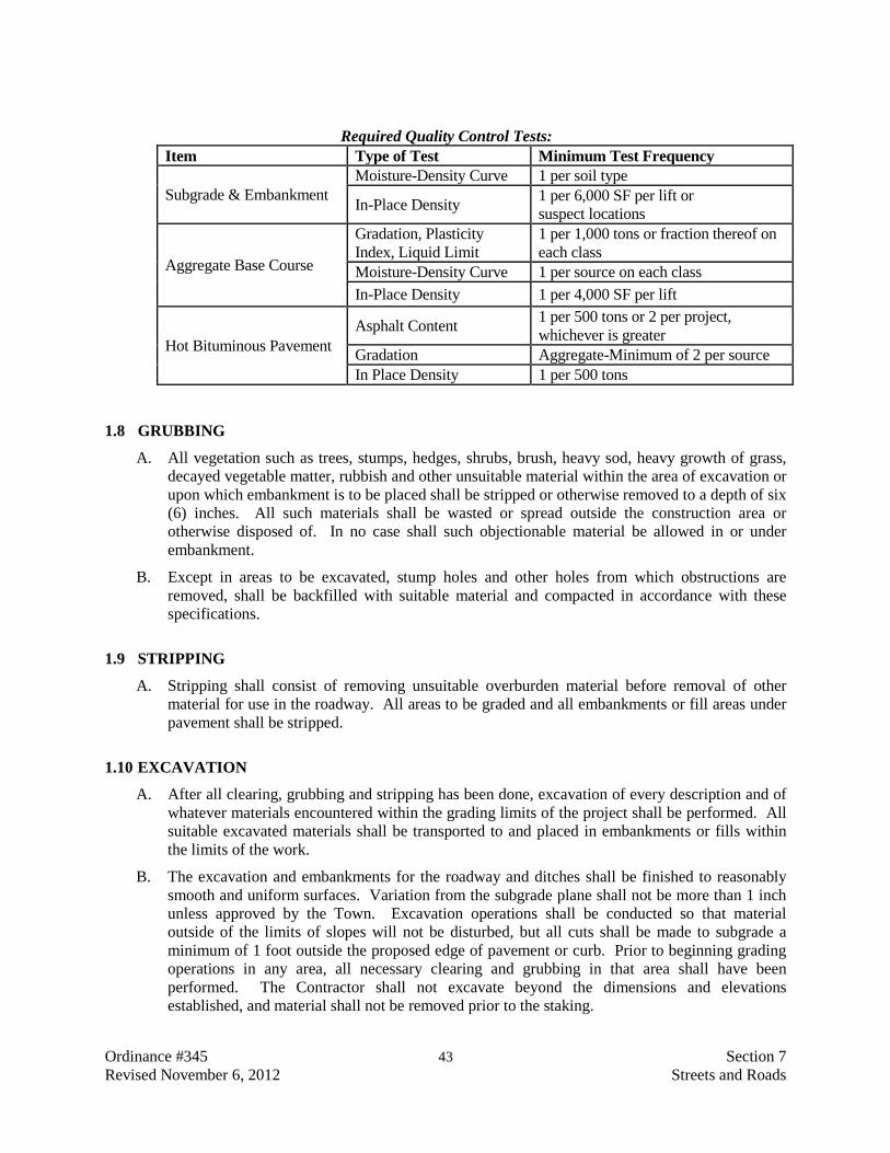
Ordinance #345 43 Section 7 Revised November 6, 2012 Streets and Roads
Required Quality Control Tests: Item Type of Test Minimum Test Frequency
Subgrade & Embankment Moisture-Density Curve 1 per soil type
In-Place Density 1 per 6,000 SF per lift or suspect locations
Aggregate Base Course
Gradation, Plasticity Index, Liquid Limit
1 per 1,000 tons or fraction thereof on each class
Moisture-Density Curve 1 per source on each class In-Place Density 1 per 4,000 SF per lift
Hot Bituminous Pavement Asphalt Content 1 per 500 tons or 2 per project,
whichever is greater Gradation Aggregate-Minimum of 2 per source In Place Density 1 per 500 tons
1.8 GRUBBING
A. All vegetation such as trees, stumps, hedges, shrubs, brush, heavy sod, heavy growth of grass, decayed vegetable matter, rubbish and other unsuitable material within the area of excavation or upon which embankment is to be placed shall be stripped or otherwise removed to a depth of six (6) inches. All such materials shall be wasted or spread outside the construction area or otherwise disposed of. In no case shall such objectionable material be allowed in or under embankment.
B. Except in areas to be excavated, stump holes and other holes from which obstructions are removed, shall be backfilled with suitable material and compacted in accordance with these specifications.
1.9 STRIPPING
A. Stripping shall consist of removing unsuitable overburden material before removal of other material for use in the roadway. All areas to be graded and all embankments or fill areas under pavement shall be stripped.
1.10 EXCAVATION
A. After all clearing, grubbing and stripping has been done, excavation of every description and of whatever materials encountered within the grading limits of the project shall be performed. All suitable excavated materials shall be transported to and placed in embankments or fills within the limits of the work.
B. The excavation and embankments for the roadway and ditches shall be finished to reasonably smooth and uniform surfaces. Variation from the subgrade plane shall not be more than 1 inch unless approved by the Town. Excavation operations shall be conducted so that material outside of the limits of slopes will not be disturbed, but all cuts shall be made to subgrade a minimum of 1 foot outside the proposed edge of pavement or curb. Prior to beginning grading operations in any area, all necessary clearing and grubbing in that area shall have been performed. The Contractor shall not excavate beyond the dimensions and elevations established, and material shall not be removed prior to the staking.

Ordinance #345 44 Section 7 Revised November 6, 2012 Streets and Roads
C. If excavation to the finished graded section encounters a subgrade or slopes of spongy material, vegetable matter or trash pockets, or standing water, the Town may require the Contractor to remove the unsuitable materials and backfill to the finished graded section with suitable material. Subgrade stabilization material (Class 2, Aggregate Classification Table, or similar material) may be used to backfill the excavations of unsuitable material. The Town may designate as unsuitable those soils or materials that are, in the Town’s judgment, detrimental to the finished roadway. All unsuitable material shall be disposed of outside the construction area.
D. Geotextile materials and various aggregate combinations may be considered for stabilization of yielding materials provided that the methodology is recommended by a geotechnical engineer and approved by the Town.
1.11 SHOULDERING AND MISCELLANEOUS WORK
A. The Contractor shall deposit sufficient suitable earth between curb and sidewalks, or property lines, so that when smoothed and consolidated in final deposition, it will provide a uniform smooth slope from top of curb to the adjacent sidewalk or property line. All broken concrete, trash and debris shall be removed before any fill is placed back of the curb. In case excavation is necessary to accomplish the above purpose, the Contractor shall make such necessary excavation, and the Contractor shall leave the area so filled or excavated free from all trash and debris.
B. The Contractor shall set all manholes, water boxes or other service boxes, to the proper finished grade of the pavement or of the fill behind the curb, as appropriate.
1.12 EMBANKMENTS
A. Embankment construction shall consist of constructing roadway embankments, including preparation of the areas upon which they are to be placed; the construction of dikes; the placing and compacting of approved material within project areas where unsuitable material has been removed; and the placing and compacting of embankment material in holes, pits and other depressions within the project area. Only approved materials shall be used in the construction of embankments and backfills.
B. Free running water shall be drained from the material before the material is placed. Rocks, broken concrete or other solid materials more than 6 inches in greatest dimension shall not be placed in embankment areas higher than 1 foot from the finished subgrade. All fill material shall be free from roots, organic material, trash and frozen material.
C. When an embankment is to be placed and compacted on hillsides, or when new embankment is to be compacted against existing embankments, or when embankment is built one-half width at a time, the slopes that are steeper than 4:1 when measured longitudinally or at right angles to the roadway shall be continuously benched over those areas where it is required as the work is brought up in layers. Benching shall be well keyed and where practical a minimum of 8 feet wide. Each horizontal cut shall begin at the intersection of the original ground and the vertical sides of the previous cuts. Material thus cut out shall be recompacted along with the new embankment material at the Contractor’s expense.
D. Embankment material shall be placed in horizontal layers not to exceed 8 inches in loose depth and compacted prior to placing each following layer. The lift thickness shall not exceed the

Ordinance #345 45 Section 7 Revised November 6, 2012 Streets and Roads
compaction capabilities of the equipment used. The maximum allowable lift thickness for hand operated jumping jack compactors shall not exceed four (4) inches in uncompacted thickness.
E. The Contractor shall add moisture to or dry by aeration each layer as may be necessary to meet the requirements for compaction. Materials shall not be placed in embankments or fills when the moisture content exceeds 4% above or is 3% below optimum moisture content for that material or as recommended in the project geotechnical report. Under roadways and extending one (1) foot beyond proposed curb line measured perpendicular from the centerline, embankments shall be compacted for the entire depth of the fill to a density of not less than 90% maximum dry density as determined by the modified proctor method ASTM D1557/AASHTO T180.
1.13 SUBGRADE PREPARATION
A. After all necessary grading has been done to bring the surface to the subgrade, the subgrade shall be scarified and compacted to a depth of 8 inches. The entire road bed width, 8 inches deep, shall be compacted to a density of not less than 90% of maximum dry density as determined by the modified proctor method ASTM D1557/AASHTO T180. If necessary, subgrade stabilization material may be used to achieve the specified compaction. Failure to attain the specified density shall be cause for rescarifying and recompacting.
B. Proof rolling may be required at the discretion of the Town. Proof rolling shall be performed as described in Section 203.09 Proof Rolling of the CDOT Standard Specifications for Road and Bridge Construction.
C. Aggregate base course shall not be placed upon the subgrade or any previously placed layer of the pavement section until compaction tests are taken and approved by the Town. Testing shall include but not be limited to trenches for water, sanitary, storm, telephone, gas, electric and around manholes, valve boxes, or inlets. After the required test results are approved by the Town, the subgrade shall be struck off and rolled with a smooth roller and shall not vary more than ±0.04 foot for the specified grade and cross section as shown on the plans.
1.14 BASE COURSE AGGREGATE
A. Aggregates shall be crushed stone, crushed slag, crushed gravel or natural gravel which conforms to the requirements of AASHTO M147. Aggregate shall meet the grading requirements in the Classification Table below. The type used shall be specified on the plans or specifications. The liquid limit (LL) shall be as shown in the table and the plasticity index (PI) shall not exceed 6 when the aggregate is tested in accordance with AASHTO T89 and T90, respectively.
B. In advance of the beginning of placing any aggregates, the Contractor shall submit suitable samples of the proposed material to an approved Materials Testing Laboratory for tests to determine the compliance with the requirements of this specification. The results of all tests shall be submitted to the Town for approval prior to the placement of any aggregate material. Tests shall be at the Contractor’s expense.
1.15 BASE COURSE PLACEMENT AND COMPACTION
A. The base course material shall be placed on the previously prepared subgrade. The subgrade shall be graded and rolled to a smooth and uniform surface free of cracks and soft spots with

Ordinance #345 46 Section 7 Revised November 6, 2012 Streets and Roads
Classification Table for Aggregate Base Course
Siev
e D
esig
natio
n Percentage by Weight Passing Square Mesh Sieves LL not greater than 35 LL not greater than 30
Class 1
Class 2
Class 3
Class 4
Class 5
Class 6
Class 7
4 inch ... 100 ... ... ... ... ... 3 inch ... 95-100 ... ... ... ... ... 2½ inch 100 ... ... ... ... ... ... 2 inch 95-100 ... ... 100 ... ... ... 1½ inch ... ... ... 90-100 100 ... ... 1 inch ... ... ... ... 95-100 ... 100 ¾ inch ... ... ... 50-90 ... 100 ... No. 4 30-65 ... ... 30-50 30-70 30-65 ... No. 8 ... ... ... ... ... 25-55 20-85 No. 200 3-15 3-15 20 max. 3-12 3-15 3-12 5-15 Note: Class 3 material shall consist of bank or pit run material
approximate optimum moisture obtained immediately prior to placement of base course. The base course material shall be placed on the previously prepared subgrade at the locations and in the proper quantities to conform to the typical cross sections as shown on the plans. Placing and spreading shall be done by means of spreader machine, moving vehicle, motor grader or other approved equipment methods. The material shall be placed without segregation. Any segregated areas shall be removed and replaced with uniformly graded material at the Contractor’s expense.
B. Each layer of base course material shall be placed in layers not to exceed six (6) inches in loose depth. Each layer shall be wetted or aerated, if necessary, and compacted to not less than 95% of maximum density as determined by the modified proctor method ASTM D1557/AASHTO T180. If water is needed, it shall be uniformly applied as necessary during compaction to obtain optimum moisture content and to aid in consolidation. The surface of each layer shall be maintained during the compaction operations in such a manner that a uniform texture is produced and the aggregates are firmly keyed. No base course material shall be placed upon a soft, spongy or frozen subgrade or other subgrade, the stability of which is, in the opinion of the Town, unsuitable for the placement thereof. The Town’s representative shall inspect each lift after placement.
C. The finished base course surface shall be smooth and free of ruts and irregularities and true to grade and crown as shown on the plans. The final surface shall be finished with a surface smoothness tolerance of 1/4 inch measured as vertical ordinate from the face to a ten-foot straightedge laid parallel or 3/8 inch perpendicular to the station line. The base course shall be maintained in this condition by watering, drying, rolling or blading, as necessary until the surfacing is placed.
D. In-place field density determinations shall be made in accordance with AASHTO T191, Density of Soil In-Place by the Sand Cone Method, or AASHTO T310 In Place Density and Moisture Content of Soil and Soil-Aggregate by Nuclear Methods (Shallow Depths).

Ordinance #345 47 Section 7 Revised November 6, 2012 Streets and Roads
1.16 PLANT MIX HOT BITUMINOUS PAVEMENT
A. The bituminous pavement shall be composed of a mixture of aggregate, filler if required, and bituminous material, hot mixed at a central plant and placed on the prepared base in conformity with the cross section and grades shown on the approved plans.
1.17 TESTING
A. The Contractor, at the Contractor’s expense, shall submit suitable samples of all materials proposed for use on the project to the Town’s materials testing laboratory. The testing laboratory shall, at the Contractor’s expense, test all materials for compliance with these specifications and establish a job mix formula for each mixture proposed for use on the project.
B. The job mix formula for each mixture shall establish a single percentage of aggregate passing each required sieve size, a single percentage of bituminous material to be added to the aggregate, and a single temperature at which the mixture is to be mixed. The job mix formula shall be within the master range specified in the following subsection. The job mix formula may be derived by either the Marshall (ASTM 1559) (AASHTO T245) or the Hveem methods (AASHTO T246) (ASTM 1560) but shall employ all current, applicable AASHTO, ASTM or Asphalt Institute procedures. As part of the development of the job mix formula, an immersion compression test (AASHTO T165) will be performed on a sample made at the optimum asphalt cement content to determine the effect of water on the cohesion of the compacted bituminous mixture.
C. The aggregate source is undesignated but test results proving that the aggregate meets these specifications must be submitted to the Town with the job mix formula. The aggregate must be tested for size and grading, cleanliness and soundness, toughness, surface texture and particle shape, absorption and stripping potential using current, applicable AASHTO, ASTM and/or Asphalt Institute procedures.
D. Test results must be submitted to the Town before paving is to begin and the Engineer’s approval must be obtained in writing before any paving is begun.
E. Job mix formula testing will not have to be conducted for each new paving project if a mix formula conforming to these specifications has previously been established using the same aggregate source that the Contractor is proposing for this project. The test results and mix formula from the earlier lab tests shall then be submitted to the Town for approval before paving begins.
1. To receive approval of the job mix formula, a written statement is required with the job mix submittal from the lab performing the earlier tests verifying that: (1) the Contractor’s proposed aggregate is the same as that of the previously established mix formula and (2) the performance of the two mixes, produced under similar conditions, will essentially be the same, with proper allowances for testing deviation.
2. Should a change in sources of materials be made, a new job-mix formula shall be established before the new material is used. When unsatisfactory results make it necessary, the Town may require the Contractor to establish a new job-mix formula.

Ordinance #345 48 Section 7 Revised November 6, 2012 Streets and Roads
PART 2 PRODUCTS
2.1 MATERIALS
A. Asphalt - Asphalt cement shall adhere to the performance grade asphalt cement used in the job mix formula unless otherwise permitted by the Town Engineer in writing.
B. Prime Coat Asphalt - Cutback asphalt for prime coat shall be MC-70 complying with the requirements of AASHTO M82. Emulsified asphalt may be substituted where special construction methods, as outlined in Article 3.1 of this section, are followed. Emulsified asphalt shall conform to those requirements specified under Article 2.1.C Tack Coat. Emulsified asphalt shall not be permitted for overlay construction.
C. Tack Coat - Emulsified asphalt for tack coat shall be SS-1, SS-1h, CSS-1 or CSS-1h diluted one part water to one part emulsified asphalt. Before dilution the emulsified asphalt shall comply with the requirements of AASHTO M140 or M208.
D. Aggregate - Mineral aggregate shall consist of hard, durable particles or fragments of crushed stone or gravel which shall be free from disintegrated stone, vegetable matter, clay lumps or other deleterious substances. Aggregate shall conform to the following grading limits (Grading SX):
Sieve Size Percent by Weight Passing Square Mesh Sieves
3/4” 100 1/2” 90-100 3/8” -- #4 -- #8 28-58 #30 -- #200 2-10
1. The aggregate shall also conform to the following requirements:
a. Percentage of wear, Los Angeles Test (AASHTO T96), not more than 35.
b. At least 90 percent of the gravel retained on the No. 4 sieve shall have at least two fractured faces.
c. When tested for stripping potential (AASHTO T182), aggregate shall have a retained bituminous film of above 95 percent.
d. The aggregate shall be non-plastic when the aggregate is tested in accordance with AASHTO T90.
E. Mineral Filler - If mineral filler is required to meet gradation or strength requirements, finely
powdered limestone, Portland cement, hydrated lime or other approved materials may be used for the filler.
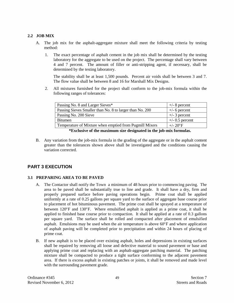
Ordinance #345 49 Section 7 Revised November 6, 2012 Streets and Roads
2.2 JOB MIX
A. The job mix for the asphalt-aggregate mixture shall meet the following criteria by testing method:
1. The exact percentage of asphalt cement in the job mix shall be determined by the testing laboratory for the aggregate to be used on the project. The percentage shall vary between 4 and 7 percent. The amount of filler or anti-stripping agent, if necessary, shall be determined by the testing laboratory.
The stability shall be at least 1,500 pounds. Percent air voids shall be between 3 and 7. The flow value shall be between 8 and 16 for Marshall Mix Designs.
2. All mixtures furnished for the project shall conform to the job-mix formula within the following ranges of tolerances:
Passing No. 8 and Larger Sieves* +/- 8 percent Passing Sieves Smaller than No. 8 to larger than No. 200 +/- 6 percent Passing No. 200 Sieve +/- 3 percent Bitumen +/- 0.5 percent Temperature of Mixture when emptied from Pugmill Mixers +/- 20°F
*Exclusive of the maximum size designated in the job-mix formulas.
B. Any variation from the job-mix formula in the grading of the aggregate or in the asphalt content greater than the tolerances shown above shall be investigated and the conditions causing the variation corrected.
PART 3 EXECUTION
3.1 PREPARING AREA TO BE PAVED
A. The Contactor shall notify the Town a minimum of 48 hours prior to commencing paving. The area to be paved shall be substantially true to line and grade. It shall have a dry, firm and properly prepared surface before paving operations begin. Prime coat shall be applied uniformly at a rate of 0.25 gallons per square yard to the surface of aggregate base course prior to placement of hot bituminous pavement. The prime coat shall be sprayed at a temperature of between 120°F and 130°F. Where emulsified asphalt is applied as a prime coat, it shall be applied to finished base course prior to compaction. It shall be applied at a rate of 0.3 gallons per square yard. The surface shall be rolled and compacted after placement of emulsified asphalt. Emulsions may be used when the air temperature is above 60°F and where application of asphalt paving will be completed prior to precipitation and within 24 hours of placing of prime coat.
B. If new asphalt is to be placed over existing asphalt, holes and depressions in existing surfaces shall be repaired by removing all loose and defective material to sound pavement or base and applying prime coat and replacing with an asphalt-aggregate patching material. The patching mixture shall be compacted to produce a tight surface conforming to the adjacent pavement area. If there is excess asphalt in existing patches or joints, it shall be removed and made level with the surrounding pavement grade.

Ordinance #345 50 Section 7 Revised November 6, 2012 Streets and Roads
C. A tack coat shall be applied uniformly at the rate of 0.10 gallons per square yard between layers of hot bituminous pavement (either between new layers or existing and new layers). Emulsified asphalt tack coat is not allowed between layers of asphalt concrete. Likewise, surfaces of curbs, gutters, vertical faces of existing pavements, and all structures to be in actual contact with the asphalt-aggregate mixture shall be given a thin, even coating of asphaltic material. Care shall be taken to prevent splattering, with asphalt, surfaces that will not be in contact with the asphalt-aggregate mixture. Immediately prior to application of the asphalt tack coat, all loose and foreign material shall be removed by sweeping or by blowing, or both.
3.2 BITUMINOUS MIXING PLANT
A. The aggregate shall be dried and heated to provide a paving mixture temperature in conformance with placing conditions, but not to exceed 163°C (325°F).
B. The heated and dried aggregates shall not contain enough moisture to cause the mixture to slump, the asphalt to foam, or the aggregate to segregate during hauling and placing, or to interfere with the proper adhesion of the asphalt aggregate mixture.
C. Mixing time shall be the shortest time that will produce a satisfactory mixture. It will be established by the Contractor based on the procedure for determining the percentage of coated particles described in AASHTO T195 (ASTM D2489). The mixing times will be set to achieve 95 percent of coated particles for all mixtures.
D. The aggregates shall be combined in the mixer in the amount of each fraction of aggregates required to meet the job-mix formula. The bituminous material shall be measured or gauged and introduced into the mixer in the amount specified by the job-mix formula.
E. The job-mix temperature at the mixer discharge (for pugmill or dryer drum) shall be between 245°F and 300°F. Mixtures shall be delivered for use on the road at not less than 235°F nor greater than 290°F. The mixture shall be hauled in such a manner so that it is protected from the weather and so that the minimum temperature stated above is maintained until the mixture is unloaded into the paver.
3.3 BITUMINOUS PAVERS
A. Self-propelled bituminous pavers shall be provided and equipped with an activated screed assembly, heated if necessary, capable of spreading and finishing the bituminous plant mix material in lane widths applicable to the typical section and thickness shown in the contract. Pavers used for shoulders and similar construction shall be capable of spreading and finishing course of asphalt plan mix material in widths shown in the contract.
B. The pavers receiving hopper shall have sufficient capacity for a uniform spreading operation and shall have an automatic distribution system that will place the mixture uniformly in front of the screed.
C. The screed or strike-off assembly shall produce the specified finished surface without tearing, shoving, or gouging the mixture.
D. The paver shall be capable of operating at forward speeds consistent with uniform and continuous laying of the mixture. Stop and go operations of the paver shall be avoided.
E. The bituminous paver shall be equipped with a means of preventing the segregation of the coarse aggregate particles from the remainder of the bituminous plant mix with when that mix is

Ordinance #345 51 Section 7 Revised November 6, 2012 Streets and Roads
carried from the paver hopper back to the paver augers. The means and methods used shall be approved by the paver manufacture and may consist of chain curtains, deflector plates, or other such devices and any combination of these.
F. The following specific requirements shall apply to the identified bituminous pavers:
1. Blaw-Knox bituminous pavers shall be equipped with the Blaw-Knox Materials Management Kit (MMK).
2. Cedarapids bituminous pavers shall be those that were manufactured in 1989 or later.
3. Caterpillar bituminous pavers shall be equipped with deflector plates as identified in the December 2000 Service Magazine entitles “New Asphalt Deflector Kit {6630, 6631, 6640}”.
G. Prior to the start of using the paver for placing plan mix, the Contractor shall submit for approval a full description in writing of the means and methodologies that will be used to prevent bituminous paver segregation. Use of the paver shall not commence prior to receiving approval from the Town.
H. Pavers shall be equipped with automatic screed controls with sensors capable of sensing grade from an outside reference line, and maintaining the screed at the specified longitudinal grade and transverse slope. The sensor shall be constructed to operate form either or both sides of the paver and shall be capable of working with the following devices:
1. Ski-type device at least 30 feet in length.
2. Short ski or short shoe.
3. Control line and stakes.
I. The types of devices and controls to be furnished shall be as provided in the contract.
J. The controls shall be capable of maintaining the screed at the specified transverse slope within plus or minus 0.1 percent.
K. The screed shall be maintained at the proper elevation at each end by controlling the elevation of one end and automatically controlling the transverse slope, or by controlling the elevation of each end independently, as directed.
3.4 MIXTURE PLACEMENT
A. Before the placement of any asphalt mixture, the Contractor shall notify the Town of Bayfield, giving a minimum of 48 hours advance notice.
B. Rollers shall be of the steel wheel, vibratory, pneumatic tire type or combination and shall be in good condition, capable of reversing without backlash.
C. The base course mixture shall be placed in one or more lifts with an asphalt paver to provide a nominal compacted thickness. The minimum lift thickness shall be at least two times the maximum particle size. The maximum lift thickness shall be 2-1/2 to 3 inches, or that which can be demonstrated to be laid in a single lift and compacted to required uniform density and smoothness, or as approved by the Town. The Town’s representative shall inspect each lift after placement.

Ordinance #345 52 Section 7 Revised November 6, 2012 Streets and Roads
D. Placing the mixture shall be a continuous operation. If any irregularities occur, they shall be corrected before final compaction of the mixture.
E. The minimum ambient temperature at the time of placement shall be 40°F and rising unless specifically approved by the Town. No asphalt shall be laid on a wet or damp base. The Town shall determine if the base is suitable for placement.
F. The longitudinal joint in one layer shall offset that in the layer immediately below by approximately 6 inches; however, the joints in the top layer shall be located as follows: For 2-lane roadway, at the centerline of the pavement and at the outside edge of the travel lanes.
G. On areas where irregularities or unavoidable obstacles make the use of mechanical spreading or finishing equipment impracticable, the mixture shall be spread, raked and luted by hand tools. For such areas, the mixture shall be dumped, spread and screed by hand to give the required compacted thickness.
3.5 COMPACTION
A. The mix shall be compacted immediately after placing. Initial rolling shall follow the paver as closely as possible. If needed, intermediate rolling with a pneumatic-tired roller shall be done immediately behind the initial rolling. Final rolling shall eliminate marks from previous rolling. In areas too small for the roller, a vibrating plate compactor or a hand tamper shall be used to achieve thorough compaction.
B. The surface shall be rolled when the mixture is in the proper condition and when the rolling does not cause undue displacement, cracking or shoving. Unless otherwise directed, rolling shall begin at the sides and proceed longitudinally parallel to the road center line, each trip overlapping one-half the roller width, gradually progressing to the crown of the road.
C. Any displacement occurring as a result of the reversing of the direction of the roller, or from other causes, shall be corrected at once by the use of rakes and addition of fresh mixture when required. Care shall be exercised in rolling not to displace the line and grade of the edges of the bituminous mixture.
D. To prevent adhesion of the mixture to the rollers, the wheels shall be kept properly moistened with water. Use of excess water will not be permitted.
E. Any mixture that becomes loose and broken, mixed with dirt, or is in any way defective shall be removed and replaced with fresh hot mixture, which shall be compacted to conform with the surrounding area. Any area showing an excess or deficiency of bituminous material shall be removed and replaced.
3.6 JOINTS
A. Placing of the bituminous paving shall be as continuous as possible. Rollers shall not pass over the unprotected end of a freshly laid mixture unless authorized by the Town. Transverse joints shall be formed by cutting back on the previous run to expose the full depth of the course. A coat of bituminous material shall be used on contact surfaces of all joints just before additional mixture is placed against the previously rolled material.

Ordinance #345 53 Section 7 Revised November 6, 2012 Streets and Roads
3.7 SURFACE TOLERANCES
A. The variation between any two contacts with the surface shall not exceed 3/16 inch in 10 feet. All humps or depressions exceeding the specified tolerance shall be corrected by removing defective work and replacing it with new material or by overlaying (patching) as directed by the Town Engineer. The final pavement surface shall not vary from the theoretical cross section by more than one (1) inch at any one point.
B. The final surface pavement adjacent to concrete gutter, for a simple crown catch curb, shall be finished from 1/8 inch to 3/8 inch above the lip of the gutter into which it drains. The final pavement surface adjacent to spill curb shall be finished flush.
C. Any surface pavement that is above the lip more than 3/8 inch shall be removed and replaced to the specified height. Any surface pavement that is below the lip of the gutter shall be corrected as specified above.
3.8 MANHOLES AND VALVE BOXES
A. All manholes and valve boxes shall be brought to 1/4 inch below finished grade by the Contractor before the surface course is placed. The Town shall inspect all manholes and valve boxes. The Contractor shall remove any foreign matter introduced into them by the Contractor’s work. It shall also be the Contractor’s responsibility to insure proper compaction around all manholes and valve boxes after they have been raised. As an alternate, valve boxes and manholes may be raised after completion of the final lift and backfilled. Asphalt shall be neatly cut with a saw to provide a square cutout. Dimension of the cutout shall be 24 inches square on water valve boxes and 48 inches square on manholes and valve clusters. Boxes and manholes shall be centered on the cutouts. Concrete for the cutouts shall be as shown on the detail sheets. Diamonds shall point in the direction of traffic and have a sawcut or tooled contraction joint from each point to the center.
3.9 ACCEPTANCE REQUIREMENTS
A. In addition to all other required tests described in previous sections, acceptance of paving will be based upon density tests conducted by a testing laboratory approved by the Town. The temperature of the asphalt material will be measured and recorded by the Contractor as the mixture is being placed. A sufficient number of samples shall be chosen at random at the job site to perform an asphalt content (extraction) test, (AASHTO T164) or Determining the Asphalt Binder Content of Hot Mix Asphalt by the Ignition Method (AASHTO T308), aggregate grading of the extracted aggregate (AASHTO T30), and the maximum theoretical density, as determined by AASHTO T209.
B. After the asphalt pavement has been rolled and has cooled, two four-inch diameter cores will be sampled from that mat. These cores will be measured for thickness and density (AASHTO T230). This density will be compared to the density of the Marshall briquettes to determine the percent compaction of the cores.
C. As an alternative to core sampling, the compacted layers of asphalt can be tested for density using a nuclear device in accordance with ASTM D2950. The nuclear gauge used must be correlated with core sample densities per the test procedure. Uncorrelated nuclear field density tests will not be accepted.

Ordinance #345 54 Section 7 Revised November 6, 2012 Streets and Roads
D. Each day’s paving and each layer of compacted asphalt will be tested as specified above. For acceptance by the Town, the average of the field density determinations must be between 92 and 96 percent of the maximum theoretical density, with no individual determination being lower than 90 percent nor greater than 98 percent.
3.10 INSPECTION AND ACCEPTANCE OF WORK
A. The Town shall at all times have access to the work during construction. All work done and all materials furnished shall be subject to inspection and approval. Work and materials not meeting the requirements shall be made good, and unsuitable work or materials may be rejected. All work which has been rejected shall be remedied, or removed and replaced in an acceptable manner.
B. When the Town has made a final inspection and determines that the work has been completed in all respects, and after Record Drawings are submitted, the Town will formally accept the improvements in writing. Record Drawings, meeting the requirements of Section 1, Article 1.3, must be submitted before the warranty period begins.
3.11 CONTRACTOR’S GUARANTEE
A. The Contractor shall guarantee all portions of street construction for a period of two years after acceptance by the Town against defective workmanship and materials and shall keep same in good order and repair. The determination of the necessity, during such guarantee period, for the Contractor to repair said street, or any portion thereof, shall rest entirely with the Town, whose decision upon the matter shall be final and obligatory upon the Contractor.
B. Any repairs identified during the warranty inspection shall be repaired and guaranteed for an additional six months beyond the original guarantee period.
END OF SECTION

Ordinance #345 55 Section 8 Revised November 6, 2012 Concrete Curb, Gutter and Sidewalk
SECTION 8
CONCRETE CURB, GUTTER AND SIDEWALK
PART 1 GENERAL
1.1 SUMMARY
A. This section covers the criteria to be used for the construction of curbs, gutters, sidewalks, curb ramps, driveway approaches, and cross gutters. See also Standard Details Nos. C-01 through C-05 for requirements.
1.2 SEQUENCE OF CONSTRUCTION
A. In areas of new development or other areas where utility lines have not been installed, all curb, gutter and sidewalk shall be constructed only after installation of sanitary sewer, storm sewer, water, gas, electric, telephone and television lines have been completed and properly compacted in accordance with applicable sections of these specifications.
B. Prior to any excavation, the Contractor shall inspect the location of proposed sidewalks and determine where tree roots may be encountered during excavation for sidewalk construction. The Contractor shall notify the Town of Bayfield prior to beginning construction when it appears that tree roots may be encountered during excavation.
C. When tree roots are unexpectedly encountered during construction, the Contractor shall discontinue work in the area where roots are encountered and shall contact the Town of Bayfield to determine what steps to take to preserve the trees and the future sidewalk.
PART 2 PRODUCTS
2.1 CEMENT
A. Cement used shall conform to the Standard Specification for Portland Cement (AASHTO M85), Type I, IA, II or IIA. When approved by the Town Engineer, Type III or IIIA, High Early Strength cement may be used.
2.2 CONCRETE
A. Concrete shall be mixed in accordance with a mix design prepared by a professional engineer registered in the State of Colorado. Concrete shall be composed of cement, coarse and fine aggregate, water and entrained air. The concrete shall have an air content of 6½% ± 1½% by volume and a maximum coarse aggregate size of 1½ inches. The laboratory design concrete shall have a minimum compressive strength at 28 days of 3,000 psi, and a minimum cement content of 565 lbs./cu. yd.. All material sources in the mix design shall be identified and material certifications shall be included with the mix design. All bulk cement shall be weighed on an approved weighing device. Any admixture except air entraining agent must be approved by the

Ordinance #345 56 Section 8 Revised November 6, 2012 Concrete Curb, Gutter and Sidewalk
Town, including accelerators retarders and fly ash. Air entraining admixtures shall conform to AASHTO M154, latest edition.
B. Concrete shall have a slump of not less than one (1) inch nor more than four (4) inches when tested in accordance with Standard Method of Test for Slump of Portland Cement Concrete AASHTO T119. The water cement ratio shall not exceed 0.45, or the maximum mix design water cement ratio unless approved by the Town. When determining the water cement ratio, cement shall be the sum of the weights of the cement and the fly ash.
C. The use of calcium chloride in any concrete is prohibited unless approved in writing by the Town of Bayfield.
2.3 AGGREGATE
A. Coarse aggregate for concrete shall conform to the requirements of AASHTO M80 having clean, hard, strong, durable pieces, free from adherent coatings and conforming to the following gradation:
AASHTO #4 Grading AASHTO #67 Grading
Sieve Designation 1½” Coarse Aggregate Percent Passing
¾” Coarse Aggregate Percent Passing
2 inch 100 -- 1½ inch 90-100 -- 1 inch 20-55 100 ¾ inch 0-15 90-100 3/8 inch 0-5 20-55 No. 4 -- 0-10 No. 8 -- 0-5
B. Fine aggregate for concrete shall conform to the requirements of AASHTO M 6 and meeting
the following gradation:
Sieve Designation Percent Passing 3/8 Inch 100 No. 4 95 - 100 No. 8 80 - 100 No. 16 45 - 80 No. 30 25 - 60 No. 50 10 - 30 No. 100 2 - 10
2.4 WATER
A. Water used for mixing or curing concrete shall be potable, clean and free from injurious amounts of oils, acids, salt, alkali, organic materials or other substances that may be deleterious to the concrete.
2.5 EXPANSION JOINT MATERIAL
A. Expansion joint materials shall be 1/4-inch thick non-extruding preformed joint filler and shall conform to AASHTO M33.

Ordinance #345 57 Section 8 Revised November 6, 2012 Concrete Curb, Gutter and Sidewalk
2.6 PLASTIC FILM
A. Plastic film used for moisture retention during concrete curing shall have a minimum thickness of 4 mils, shall be black, white or clear in color and meet the requirements of AASHTO M171.
2.7 CURING COMPOUND
A. Curing compound shall be white pigmented, liquid, membrane-forming compounds conforming to AASHTO M148, Type 2, Class B (vehicle solids restricted to all resin material), or other compounds, as approved by the Town. Curing compounds shall be applied in accordance with the manufacturer’s directions.
2.8 FORMS
A. Forms shall be metal or wood and shall have a depth equal to or greater than the section being placed. The supply of forms shall be sufficient to permit their remaining in place for a minimum of six (6) hours after the concrete has been placed. Each section of form shall be straight and free from warps and bends and of sufficient strength to resist the pressure of the concrete without springing. Bracing and staking of forms shall be such that the forms remain in both horizontal and vertical alignment until their removal. Maximum deviations of the top surface shall not exceed one-eighth (1/8) inch in ten (10) feet. The method of connection between sections shall be such that the joint thus formed is tight and free from movement in any direction. Care shall be taken in removing forms to prevent marring or spalling of the concrete.
B. The forms shall be thoroughly cleaned each time they are used and coated with an approved form-release agent which will not discolor or stain the concrete.
C. When pouring concrete gutter adjacent to existing asphalt paving, the edge of the asphalt may not be used as a form for the new concrete unless the edge is saw cut and approved for such use prior to concrete placement. The gutter shall be formed as described above and the pavement patched according to these specifications upon completion of the concrete work.
2.9 AGGREGATE BASE COURSE
A. Aggregate base course, required under all curb, gutter and sidewalk installation shall consist of crushed stone or gravel, and shall conform to the requirements for CDOT Class 6, Aggregate Base Course.
2.10 TESTS
A. Tests on the aggregate base course shall be performed by an approved testing laboratory, with the results submitted to the Town Engineer. The base course shall be compacted to not less than 95% of maximum density as determined by the modified proctor method ASTM D1557/AASHTO T180. The frequency of tests required will be as follows:
1. Smaller projects – under 30 linear feet of installed curb and gutter, and/or sidewalk, one density test will be required.
2. Larger projects – density testing will be required every 300 linear feet, or one test per Town block.

Ordinance #345 58 Section 8 Revised November 6, 2012 Concrete Curb, Gutter and Sidewalk
B. A series of concrete tests will be performed by an approved testing laboratory and the results submitted to the Town for approval before any curb and gutter and/or sidewalk project will be accepted by the Town. The number of tests required will be as follows:
1. Smaller projects - Under 30 linear feet of installed curb, gutter and sidewalk or under 30 linear feet of either installed curb and gutter or installed sidewalk. Slump, air content and temperature test with certified batch ticket and statement of cement, water and aggregate content will be required.
2. Larger projects - Each day of concrete pouring, or for each 50 cubic yards of concrete poured, whichever is greater, a complete series of tests, all conducted according to current, applicable AASHTO or ASTM procedures are required:
a. Slump test, air content test will be performed and concrete temperature measurement taken during placement operations.
b. Comprehensive strength tests will be performed on five cylinders molded from fresh concrete at the project site. The cylinders will be cured in accordance with the latest issue of ASTM C31 and per American Concrete Institute (ACI) ACI-318. The compressive strength of one cylinder will be determined at seven days, three cylinders will be tested at 28 days and, if required by the Town, the last cylinder will be tested at 56 days. Compressive strength will be determined in accordance with ASTM C39.
C. Failure of either of the 28-day cured cylinders to attain the required minimum strength may be cause for rejection of that portion of the project represented by the cylinders, removal and replacement of all installed concrete within the failed portion, and changes in the concrete mix preparations to meet the minimum strength requirements.
D. All gutter will be water flow tested by the Contractor in the presence of the Town Inspector for outflow and ponding when it has attained sufficient hardness to properly withstand the testing. Any section of soft curb and gutter or cross gutter, unauthorized areas of outflow, or areas of ponding deeper than ¼ inch shall be carefully cut out with a concrete saw between the nearest two contraction joints (or nearest contraction and expansion joints), removed and replaced to the proper grade and cross section to eliminate the outflow or ponding problem. Full cross section expansion joints will be placed between the sections of existing and new concrete curb and gutter. The work of removal and replacement of the curb and gutter will be at the Contractors’ expense. The new sections will be retested by the Contractor in the presence of the Town Inspector to assure that the problem is corrected.
PART 3 EXECUTION
3.1 SUBGRADE PREPARATION
A. The subgrade shall be excavated to the necessary depth and width that will allow for placement of the base material and permit the installation and bracing of the forms. If necessary, the subgrade shall be filled with base material in maximum of 6-inch lifts to bring it to the required lines and grades as shown on the approved plans. All debris, roots, vegetable matter, soft, yielding soil an other existing unsuitable subgrade material shall be removed to a depth of not less than 6 inches below subgrade, or when required by the Town, to a greater depth and

Ordinance #345 59 Section 8 Revised November 6, 2012 Concrete Curb, Gutter and Sidewalk
replaced with aggregate base course. Compaction in all fill areas shall extend a minimum of one foot outside the form lines.
3.2 AGGREGATE BASE COURSE PREPARATION
A. Immediately beneath all curb and gutter and/or sidewalk installations shall be placed a minimum of 4 inches of compacted CDOT Class 6 aggregate base course. The base course material shall be shaped and compacted to a firm, even surface at the grades and elevations shown on the plans.
B. The base course shall be compacted to at least 95% of the maximum density as determined by the modified proctor method ASTM D1557/AASHTO T180. If the Town Inspector has reason to believe that the required minimum compaction is not being attained on the base material, they may require, at the Contractor’s expense, laboratory and in-place density tests using applicable, current AASHTO or ASTM procedures to be conducted by an approved testing lab on the base material. The test results will be submitted to and approved by the Town before the project will receive final acceptance by the Town.
3.3 CONCRETE MIXING
A. Job Mixed Concrete will not be allowed unless approved in writing by the Town prior to placement:
1. When concrete is mixed at the site, cement must be Type IA or IIA.
a. All concrete shall be thoroughly mixed in a batch mixer of a Town Engineer approved type and capacity for a period of not less than two minutes after all the materials, including water, have been placed in the drum. During the period of mixing, the drum shall be operated at the speed specified by the manufacturer of the equipment. The entire contents of the mixer shall be discharged before recharge and the mixer shall be cleaned frequently. The concrete shall be mixed only in such quantities as are required for immediate use.
B. Ready Mixed Concrete:
1. Ready mixed concrete shall be continuously mixed or agitated from the time the water is added until the time of use. The concrete shall be completely discharged from the truck mixer or truck agitator within one and one-half hours after the cement comes in contact with the mixing water or with the combined aggregates containing free moisture in excess of 2% by weight. Water added at the project site must not cause the water/cement ratio to exceed the mix design water/cement ratio.
2. The organization supplying ready-mixed concrete shall have sufficient plant and transportation facilities to assure continuous delivery of concrete at the required rate. The Contractor shall collect delivery or batch tickets from the ready-mix driver for each load of concrete used on the project and submit them to the Town. Tickets shall show weight of all materials and additives used in each batch.

Ordinance #345 60 Section 8 Revised November 6, 2012 Concrete Curb, Gutter and Sidewalk
3.4 RETEMPERING OF CONCRETE
A. Retempering of concrete which has partially hardened by remixing, with or without water, will not be permitted. Water may only be added to the full load. Water must not be added after concrete has been discharged from the mixer.
3.5 PLACING CONCRETE
A. The Contractor shall call for inspection, giving 24 hours notice, and inspection shall be made before placement of concrete can occur. The Town Inspector’s approval to place materials shall be obtained by the Contractor after inspection has been made and before concrete is placed. Inspection is only an aid to the Contractor and in no way reflects a responsibility on the part of the Town for quality or quantity control, and in no way implies acceptance of the work or any part thereof by the Town of Bayfield. Notice of rejection shall be given to the Contractor in the event any of the aforementioned conditions are not met, and work shall be halted until such time as corrective action is taken.
B. Before depositing concrete, debris shall be removed from the space to be occupied by the concrete, and the forms, base material and any existing concrete surface shall be thoroughly moistened immediately prior to placing of concrete. Concrete shall not be placed until all forms and compacted base course material have been inspected and approved by the Town Engineer or Inspector. The concrete shall be placed either by an approved slipform/extrusion machine, by the formed method, or by a combination of these methods. Concrete shall be handled from the mixer to the place of final deposit as rapidly as possible by methods which prevent separation or loss of ingredients. Conveying equipment shall be washed and kept clean at all times. Concrete shall be deposited in the forms as nearly in its final position as practicable to avoid rehandling.
C. Concrete shall be placed in a manner that will avoid segregation and shall not be dropped freely more than 5 feet. Necessary hand spreading shall be done with shovels and not with rakes. The concrete shall be tamped or mechanically vibrated for thorough consolidation but again without segregation of the mix. If vibrators are used, they shall be inserted and removed vertically at regular intervals to insure uniform consolidation. In no case shall vibrators be used to transport concrete inside the forms. If segregation occurs, the Town Engineer may require the affected concrete to be removed and replaced at the Contractor’s expense.
3.6 SPACING OF JOINTS
A. Expansion Joints:
1. Expansion joints shall be of ¼ inch thick non-extruding preformed joint filler material cut to the configuration of the full depth and width of the concrete section, except that joint filler shall be left ¼-inch below the surface when joints are shown to be sealed in the plans.
2. Expansion joint material (filler) shall be placed prior to placing of concrete and shall be provided at the following locations:
a. every 50 feet of curb and gutter and/or sidewalk
b. at all sides of a curb return that will be adjacent to new or existing sidewalk
c. at both edges of a driveway adjacent to any concrete
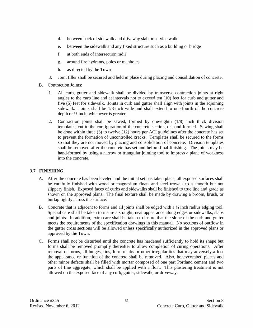
Ordinance #345 61 Section 8 Revised November 6, 2012 Concrete Curb, Gutter and Sidewalk
d. between back of sidewalk and driveway slab or service walk
e. between the sidewalk and any fixed structure such as a building or bridge
f. at both ends of intersection radii
g. around fire hydrants, poles or manholes
h. as directed by the Town
3. Joint filler shall be secured and held in place during placing and consolidation of concrete.
B. Contraction Joints:
1. All curb, gutter and sidewalk shall be divided by transverse contraction joints at right angles to the curb line and at intervals not to exceed ten (10) feet for curb and gutter and five (5) feet for sidewalk. Joints in curb and gutter shall align with joints in the adjoining sidewalk. Joints shall be 1/8-inch wide and shall extend to one-fourth of the concrete depth or ½ inch, whichever is greater.
2. Contraction joints shall be sawed, formed by one-eighth (1/8) inch thick division templates, cut to the configuration of the concrete section, or hand-formed. Sawing shall be done within three (3) to twelve (12) hours per ACI guidelines after the concrete has set to prevent the formation of uncontrolled cracks. Templates shall be secured to the forms so that they are not moved by placing and consolidation of concrete. Division templates shall be removed after the concrete has set and before final finishing. The joints may be hand-formed by using a narrow or triangular jointing tool to impress a plane of weakness into the concrete.
3.7 FINISHING
A. After the concrete has been leveled and the initial set has taken place, all exposed surfaces shall be carefully finished with wood or magnesium floats and steel trowels to a smooth but not slippery finish. Exposed faces of curbs and sidewalks shall be finished to true line and grade as shown on the approved plans. The final texture shall be made by drawing a broom, brush, or burlap lightly across the surface.
B. Concrete that is adjacent to forms and all joints shall be edged with a ¼ inch radius edging tool. Special care shall be taken to insure a straight, neat appearance along edges or sidewalks, slabs and joints. In addition, extra care shall be taken to insure that the slope of the curb and gutter meets the requirements of the specification drawings in this manual. No sections of outflow in the gutter cross sections will be allowed unless specifically authorized in the approved plans or approved by the Town.
C. Forms shall not be disturbed until the concrete has hardened sufficiently to hold its shape but forms shall be removed promptly thereafter to allow completion of curing operations. After removal of forms, all bulges, fins, form marks or other irregularities that may adversely affect the appearance or function of the concrete shall be removed. Also, honeycombed places and other minor defects shall be filled with mortar composed of one part Portland cement and two parts of fine aggregate, which shall be applied with a float. This plastering treatment is not allowed on the exposed face of any curb, gutter, sidewalk, or driveway.

Ordinance #345 62 Section 8 Revised November 6, 2012 Concrete Curb, Gutter and Sidewalk
3.8 FORMING MACHINE PLACEMENT
A. In lieu of the construction methods described in the preceding paragraphs, the Contractor may use a slipform/extrusion machine for construction of curb, gutter and sidewalk or any combination thereof. The machine shall place, shape, consolidate, screed and finish the full width and depth of the concrete section in one complete pass. This shall be done in such a manner that a minimum of hand finishing will be necessary to provide a concrete section that is uniform in texture, shape and density. All operations of mixing, delivery and spreading concrete shall be coordinated to provide uniform progress, with stopping and starting of the machine held to a minimum. The concrete edges shall be straight, smooth and true. The concrete shall be a stiff (low slump) mix. Concrete finishers shall follow the machine to form joints and correct any imperfections in the finish as described in the preceding paragraphs.
3.9 CURING
A. After finishing operations have been completed and as soon as marring of the concrete will not occur, the entire surface of the newly placed concrete will be cured by protecting it against moisture loss, rapid temperature change, and from rain, flowing water and any mechanical injury for a period of not less than seven days after placement of Type I or II cement is used. The minimum curing period shall be five days if Type III, High Early Strength cement is used. Concrete shall be cured by only one of the following methods:
3.10 LIQUID MEMBRANE FORMING CURING COMPOUND
A. This compound must conform to the requirements of Subsection 2.3.3, ACI 308 (Recommended Practice for Curing Concrete). The curing compound shall be applied immediately after the water sheen has left the finished concrete. If there is a delay between the time that the surface water has disappeared and the time that the curing compound is applied, the concrete surface shall be kept continually moist by means of a fine water spray until the compound can be applied.
B. The compound shall be applied under pressure at the manufacturer’s recommended rate (approximately 150 square feet per gallon) in a manner which covers the entire pavement with a uniform water-impermeable film. The rate will be sufficient to achieve the water retention as required in AASHTO M148. The compound shall be kept agitated during application to prevent the pigment from settling.
3.11 PLASTIC FILM
A. Plastic film shall meet the requirements of AASHTO M171 and Subsection 2.3.1, ACI 308 (Recommended Practice for Curing Concrete). In order to retain moisture in the concrete during the curing period, film shall be placed over the wet surface of the freshly finished concrete as soon as it can be done without marring the surface, and must extend at least twelve inches beyond the edges of all concrete to ensure complete coverage. The sheets shall be lapped at least 12 inches and the laps shall be secured in such a manner that they do not open up or separate. If there is a delay of placing the film immediately after concrete finishing, all exposed concrete surfaces shall be kept continually moist by means of a fine water spray until they can be covered by plastic film.
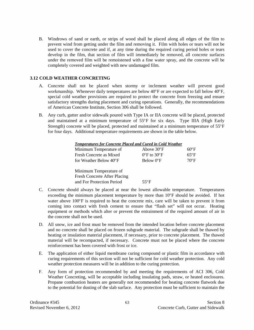
Ordinance #345 63 Section 8 Revised November 6, 2012 Concrete Curb, Gutter and Sidewalk
B. Windrows of sand or earth, or strips of wood shall be placed along all edges of the film to prevent wind from getting under the film and removing it. Film with holes or tears will not be used to cover the concrete and if, at any time during the required curing period holes or tears develop in the film, that section of film will immediately be removed, all concrete surfaces under the removed film will be remoistened with a fine water spray, and the concrete will be completely covered and weighted with new undamaged film.
3.12 COLD WEATHER CONCRETING
A. Concrete shall not be placed when stormy or inclement weather will prevent good workmanship. Whenever daily temperatures are below 40°F or are expected to fall below 40°F, special cold weather provisions are required to protect the concrete from freezing and ensure satisfactory strengths during placement and curing operations. Generally, the recommendations of American Concrete Institute, Section 306 shall be followed.
B. Any curb, gutter and/or sidewalk poured with Type IA or IIA concrete will be placed, protected and maintained at a minimum temperature of 55°F for six days. Type IIIA (High Early Strength) concrete will be placed, protected and maintained at a minimum temperature of 55°F for four days. Additional temperature requirements are shown in the table below.
Temperatures for Concrete Placed and Cured in Cold Weather
Minimum Temperature of Above 30°F 60°F Fresh Concrete as Mixed 0°F to 30°F 65°F for Weather Below 40°F Below 0°F 70°F
Minimum Temperature of Fresh Concrete After Placing and For Protection Period 55°F
C. Concrete should always be placed at near the lowest allowable temperature. Temperatures exceeding the minimum placement temperature by more than 10°F should be avoided. If hot water above 100°F is required to heat the concrete mix, care will be taken to prevent it from coming into contact with fresh cement to ensure that “flash set” will not occur. Heating equipment or methods which alter or prevent the entrainment of the required amount of air in the concrete shall not be used.
D. All snow, ice and frost must be removed from the intended location before concrete placement and no concrete shall be placed on frozen subgrade material. The subgrade shall be thawed by heating or insulation material placement, if necessary, prior to concrete placement. The thawed material will be recompacted, if necessary. Concrete must not be placed where the concrete reinforcement has been covered with frost or ice.
E. The application of either liquid membrane curing compound or plastic film in accordance with curing requirements of this section will not be sufficient for cold weather protection. Any cold weather protection measures will be in addition to the curing protection.
F. Any form of protection recommended by and meeting the requirements of ACI 306, Cold Weather Concreting, will be acceptable including insulating pads, straw, or heated enclosures. Propane combustion heaters are generally not recommended for heating concrete flatwork due to the potential for dusting of the slab surface. Any protection must be sufficient to maintain the

Ordinance #345 64 Section 8 Revised November 6, 2012 Concrete Curb, Gutter and Sidewalk
concrete at the minimum temperature during the required protection period. Failure to maintain the proper temperature shall be cause for rejection and replacement, at the Contractor’s expense, of the curb and gutter and/or sidewalk.
G. The Town Engineer or Inspector will measure and record the concrete temperature at least once a day during the protection period. The temperature will be obtained by placing a high-low thermometer against the concrete under a temporary cover of heavy insulating material until it registers constant temperatures.
3.13 HOT WEATHER CONCRETING
A. Concrete placement during hot weather should be conducted in accordance with ACI recommendations. Subgrade should be moistened and if needed temporary wind breaks and misting sprinklers may need to be used to prevent plastic shrinkage cracks and to prevent drying of the top surface.
3.14 OPENING TO TRAFFIC
A. It shall be the Contractor’s responsibility to protect the concrete being cured from the elements, traffic and vandalism. Inadequate protection by the Contractor shall be cause for suspension of concreting operations and damaged concrete shall be removed and replaced at the expense of the Contractor.
B. Sidewalks shall not be opened to pedestrian traffic for at least 24 hours after placement. New concrete shall not be opened to vehicular traffic for at least 7 days after placement, or until specifications have been met. Additional time may be directed by the Town Engineer. The Contractor shall maintain suitable barricades to comply with this requirement.
3.15 DAMAGE TO EXISTING PAVEMENT
A. Existing asphalt pavement which is damaged during curb and gutter construction shall be repaired at the Contractor’s expense. All jagged rough edges or cracked pavement shall be separated and removed from sound, undamaged asphalt by means of an asphalt cutter making straight, sharp cuts. If the base course has been damaged or soaked due to the concrete construction operations, it shall be removed, replaced and/or recompacted. The exposed base course, asphalt cuts and gutter face to be in contact with pavement shall be painted with hot asphalt cement immediately prior to the placement and compaction of hot asphalt mix. Cold asphalt mix will be allowed only if hot mix is not available. In either case, a minimum of 3 inches of asphalt mix will be required.
B. The surfaces of the new and existing asphalt shall match after compaction and new asphalt shall be ¼-inch to ½-inch higher than the adjacent gutter surface.
3.16 REPAIRS OF EXISTING SIDEWALKS
A. Where repairs are made in existing sidewalks, all edges of the old sidewalk allowed to remain shall be saw cut to a minimum depth of 1½ inches. No rough edges will be permitted where new construction joins old. Unless directed by the Town Engineer, no section less than 6 feet in length shall be placed or left in place. Where new sidewalk construction abuts existing

Ordinance #345 65 Section 8 Revised November 6, 2012 Concrete Curb, Gutter and Sidewalk
sidewalks, the work shall be accomplished so that no abrupt change in grade between the old and new sidewalk results.
3.17 BACKFILLING
A. When side forms are removed, the space adjoining the concrete shall be promptly backfilled with suitable material, properly compacted and brought flush with the surface of the concrete and adjoining ground surface. In embankments, the backfill shall be level with the top of the concrete for at least two (2) feet and then sloped to the property line.
3.18 CLEANUP
A. A concrete washout structure shall be required, and the washout area maintained. At the end of the project, the washout structure and any excess or remaining concrete shall be removed from the project site unless approved by the Town Engineer.
3.19 ACCEPTANCE BY TOWN
A. The Contractor will notify the Town at least 24 hours before any concrete is placed so that the Inspector may inspect the forms and base course before concreting operations begin. After or during finishing and curing procedures are completed, a final inspection will be made to verify compliance with remaining specifications. Deficiencies will immediately be repaired or replaced at the Contractor’s expense. Upon receipt of satisfactory laboratory test results (including 28 day field cured cylinder compressive tests) the Town Engineer will issue a written acceptance of the completed improvements.
B. The Contractor shall guarantee all installed curb, gutter, sidewalk, and cross gutter for a period of two years after acceptance by the Town against defective workmanship and materials. The determination of the necessity, during such guarantee period, for the Contractor to repair or replace said curb, gutter, sidewalk, and cross gutter, or any portion thereof, shall rest entirely with the Town, whose decision upon the matter shall be final and binding upon the Contractor.
END OF SECTION

Ordinance #345 66 Section 9 Revised November 6, 2012 Concrete Formwork
SECTION 9
CONCRETE FORMWORK
PART 1 GENERAL
1.1 SUMMARY
A. All formwork for cast-in-place concrete structures shall conform to the requirements specified herein. Furnishing all materials and labor for placement and removal of formwork are included. Bridge deck forms and falsework are excluded from this Specification.
1.2 QUALITY STANDARDS
A. The latest published revision of the Quality Standards in effect at time of bid shall apply: ACI 347 - Recommended Practice for Concrete Formwork.
1.3 SUBMITTALS
A. The Contractor shall submit a description of the forming system with complete details. The location of all construction joints shall be detailed. The methods proposed for securing embedded items and blockout procedures shall also be defined.
PART 2 PRODUCTS
2.1 MATERIALS
A. Form lumber for all exposed concrete surfaces shall be dressed at least on one side and two edges and shall be constructed to produce mortar-tight joints and smooth, even concrete surfaces. Forms shall be filleted and chambered and shown on the Plans. Forms shall be given a bevel or draft to assure easy removal from all projections.
B. Plywood shall be “B-B Plyform Class 1 Exterior” grade plywood, 5/8 inch minimum thickness in new or near new condition.
C. Metal forms shall be of sufficient thickness or braced to resist noticeable deflection from pressure of the concrete. All bolt and rivet heads shall be countersunk. Clamps, pins or other connecting devices shall hold the forms rigid during curing and allow removal without injury to the concrete. Metal forms which do not provide a smooth surface or do not align properly shall not be used. Metal forms shall be free from rust, grease or other foreign matter.
D. Framing, studding, and bracing shall be accomplished by use of standard or construction grade lumber, according to ACI 347.
E. Metal ties or anchorages within the forms shall be designed to permit their removal to a depth of at least ½ inch from the face without injury to the concrete allowing the ties to be grouted back. Form ties shall be designed to resist the loads imposed by freshly poured concrete and permit tightening spreading of forms. Twisted wire loop ties and wooden spreaders shall not be used.
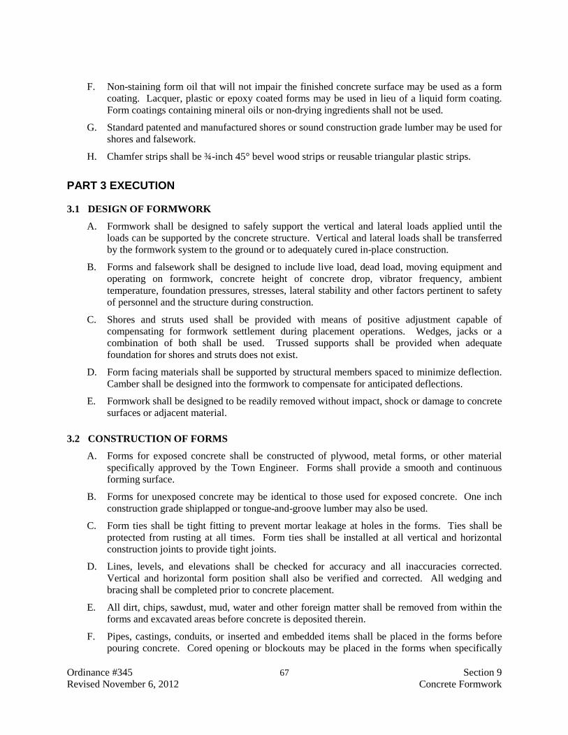
Ordinance #345 67 Section 9 Revised November 6, 2012 Concrete Formwork
F. Non-staining form oil that will not impair the finished concrete surface may be used as a form coating. Lacquer, plastic or epoxy coated forms may be used in lieu of a liquid form coating. Form coatings containing mineral oils or non-drying ingredients shall not be used.
G. Standard patented and manufactured shores or sound construction grade lumber may be used for shores and falsework.
H. Chamfer strips shall be ¾-inch 45° bevel wood strips or reusable triangular plastic strips.
PART 3 EXECUTION
3.1 DESIGN OF FORMWORK
A. Formwork shall be designed to safely support the vertical and lateral loads applied until the loads can be supported by the concrete structure. Vertical and lateral loads shall be transferred by the formwork system to the ground or to adequately cured in-place construction.
B. Forms and falsework shall be designed to include live load, dead load, moving equipment and operating on formwork, concrete height of concrete drop, vibrator frequency, ambient temperature, foundation pressures, stresses, lateral stability and other factors pertinent to safety of personnel and the structure during construction.
C. Shores and struts used shall be provided with means of positive adjustment capable of compensating for formwork settlement during placement operations. Wedges, jacks or a combination of both shall be used. Trussed supports shall be provided when adequate foundation for shores and struts does not exist.
D. Form facing materials shall be supported by structural members spaced to minimize deflection. Camber shall be designed into the formwork to compensate for anticipated deflections.
E. Formwork shall be designed to be readily removed without impact, shock or damage to concrete surfaces or adjacent material.
3.2 CONSTRUCTION OF FORMS
A. Forms for exposed concrete shall be constructed of plywood, metal forms, or other material specifically approved by the Town Engineer. Forms shall provide a smooth and continuous forming surface.
B. Forms for unexposed concrete may be identical to those used for exposed concrete. One inch construction grade shiplapped or tongue-and-groove lumber may also be used.
C. Form ties shall be tight fitting to prevent mortar leakage at holes in the forms. Ties shall be protected from rusting at all times. Form ties shall be installed at all vertical and horizontal construction joints to provide tight joints.
D. Lines, levels, and elevations shall be checked for accuracy and all inaccuracies corrected. Vertical and horizontal form position shall also be verified and corrected. All wedging and bracing shall be completed prior to concrete placement.
E. All dirt, chips, sawdust, mud, water and other foreign matter shall be removed from within the forms and excavated areas before concrete is deposited therein.
F. Pipes, castings, conduits, or inserted and embedded items shall be placed in the forms before pouring concrete. Cored opening or blockouts may be placed in the forms when specifically

Ordinance #345 68 Section 9 Revised November 6, 2012 Concrete Formwork
approved by the Town Engineer. Cores or blockout boxes shall be provided with continuous keyways or waterstops around the periphery and tapered slightly to facilitate grouting. All inserted and embedded items shall be supported to ensure accurate alignment and minimize distortion during concrete placement.
3.3 INSPECTION
A. The Town Engineer or Inspector shall inspect the forms after reinforcing steel is placed and prior to concrete placement. The Town Engineer shall be notified at least 24 hours prior to scheduled concrete placement.
3.4 FORM REMOVAL
A. Supports shall not be removed until the concrete has attained at least 80% of the specified 28 day strength or as specifically approved by the Town Engineer.
B. The forms for any portion of the structure shall not be removed until the concrete is strong enough to withstand damage when the forms are removed.
C. Side forms for cast-in-place beams, walls or other member where the forms do not resist dead load bending shall remain in place for at least 12 hours after concrete placement, exclusive of periods when ambient temperature is below 40° F.
D. Forms may be removed earlier than defined above, provided high-early strength concrete is used. Removal time shall be as specifically approved by the Town Engineer.
E. All forms shall be removed except as provided on the Plans.
F. Form removal methods shall not cause over stressing. Supports shall be removed in a sequence that permits the concrete to gradually and uniformly absorb its weight stress. Supports and forms shall not be removed by high impact methods. Ties shall be broken after concrete has cured sufficiently to maintain an unbroken bond with the tie rod.
3.5 REUSE OF FORMS
A. Used forms intended for use for exposed concrete shall be reconditioned to “like new” condition. All reused forms shall be cleaned, repaired and recoated before each reuse.
3.6 QUALITY CONTROL
A. Form movement or deflection during concrete placement that results in finished surface variations in excess of the tolerances specified may be the basis for rejection and replacement of cast-in-place concrete.
3.7 CLEAN UP
A. Forms, shores, struts, bracing, lumber and all trash shall be removed from the site upon completion of the work, and the site left in a neat and orderly condition.
END OF SECTION

Ordinance #345 69 Section 10 Revised November 6, 2012 Concrete Reinforcement
SECTION 10
CONCRETE REINFORCEMENT
PART 1 GENERAL
1.1 SUMMARY
A. All reinforcement for cast-in-place concrete structures shall conform to the requirements specified herein. Furnishing all materials and labor for placement are included.
1.2 QUALITY STANDARDS
A. The latest published revision of the Quality Standards in effect at time of bid shall apply.
B. American Association of State Highway and Transportation Officials (AASHTO)
1. AASHTO M31: Deformed and Plain Billet - Steel Bars for Concrete Reinforcement
3. AASHTO 55: Welded Steel Wire Fabric for Concrete Reinforcement
C. American Concrete Institute (ACI)
1. ACI 315: Manual of Standard Practice for Detailing Reinforced Concrete Structures
D. American Society for Testing and Materials (ASTM)
1. ASTM A185: Welded Steel Wire Fabric for Concrete Reinforcement
2. ASTM A615: Deformed and Plain Carbon-Steel Bars for Concrete Reinforcement
E. Concrete Reinforcing Steel Institute (CRSI)
1. CRSI: Manual of Standard Practice
1.3 SUBMITTALS
A. The Contractor shall submit bending and cutsheet schedules and drawings defining placing of reinforcing steel.
PART 2 PRODUCTS
2.1 MATERIALS
A. All materials, manufacturing operations, testing and inspection of concrete reinforcement shall conform to the requirements of the applicable Quality Standards listed above.
B. Reinforcing bars shall be deformed steel bars of the size and grade detailed on the Plans.
C. Welded wire fabric shall be of the gauge and mesh specified on the Plans.
D. Tie wire shall be 16 gauge black annealed steel wire, except when epoxy coated reinforcing is used.
Ordinance #345 70 Section 10 Revised November 6, 2012 Concrete Reinforcement
E. Reinforcing bar supports shall conform to Chapter 3 of CRSI Manual and shall be galvanized or plastic coated, where legs will be exposed in finished concrete surfaces. Otherwise, concrete bricks or mortar blocks may be used.
F. Reinforcement materials shall be delivered in bundles marked or identified to coordinate with the placement drawings. Materials shall be handled and stored to prevent contamination from dirt, oil and other materials that could affect bonding capacity with the concrete. Materials should be stored off ground in locations where the material shall not be subject to abuse or damage.
PART 3 EXECUTION
3.1 QUALITY CONTROL
A. Dirt, grease, oil, loose mill scale, excessive rust and foreign matter that may interfere with concrete bond shall be removed prior to placement.
B. Minimum concrete cover over the reinforcement detailed on the plans shall be maintained throughout the construction.
C. The manufacturer shall furnish certification that all of the inspections and tests have been made and the results thereof comply with the requirements of the applicable Quality Standards specified above.
D. The Contractor shall furnish the Town Engineer two copies of the manufacturer’s certificates.
3.2 CLEAN UP
A. The stockpile shall be left in a neat and orderly condition upon completion of the work.
END OF SECTION

Ordinance #345 71 Section 11 Revised November 6, 2012 Joints in Concrete
SECTION 11
JOINTS IN CONCRETE
PART 1 GENERAL
1.1 SUMMARY
A. All construction joints, expansion and contraction joints, and water-tight joints in cast-in-place concrete shall conform to the requirements specified herein. Furnishing all materials and labor for placement are included.
1.2 QUALITY STANDARDS
A. The latest published revision of the Quality Standards in effect at the time of bid shall apply.
B. American Association of State Highway and Transportation Officials (AASHTO):
1. AASHTO M33: Preformed Expansion Joint Filler for Concrete (Bituminous Type)
2. AASHTO M153: Preformed Sponge Rubber and Cork Expansion Joint Fillers for Concrete Paving and Structural Construction
3. AASHTO M173: Concrete Joint Sealer, Hot Elastic Type
4. AASHTO M213: Preformed Expansion Joint Fillers for Concrete Paving and Structural Construction.
1.3 SUBMITTALS
A. The Contractor shall submit a list of joint material to be used along with the names of the manufacturers and local suppliers.
B. The Contractor shall submit shop drawings detailing waterstop splice (weld) locations, intersection details, and support and forming details. Specifications and descriptive literature for the splice welding tools shall also be submitted along with the qualifications of the splice welder.
C. The Contractor shall submit drawings detailing all construction joints that are not shown on the Plans.
PART 2 PRODUCTS
2.1 MATERIALS
A. Joint bonding materials required for construction joints shall be as shown on the Plans or defined in the Special Provisions.
B. Joint sealer, preformed joint filler and joint waterstop materials shall conform to the requirements of the applicable Quality Standards listed above.
Ordinance #345 72 Section 11 Revised November 6, 2012 Joints in Concrete
C. Closed cell polyethylene backer-rod shall be used in sealant joints. The backer-rod shall be resilient and approved by the sealant manufacturer. Backer-rod diameter shall be 1/8 inch larger than width of groove.
PART 3 EXECUTION
3.1 CONSTRUCTION JOINTS
A. Construction joints shall be located only as shown on the Plans or as approved by the Town Engineer prior to each pour. All construction joints shall be keyed, unless shown otherwise on the Plans.
B. Reinforcement shall be continued through the joint, unless shown otherwise on the Plans.
C. Bulkheads shall be constructed to make waterstops and reinforcement to prevent concrete leakage.
D. Previously placed concrete shall be thoroughly roughened and air cleaned prior to placement of additional concrete. Place concrete continuously to a predetermined construction joint or level.
3.2 EXPANSION AND CONTRACTION JOINTS
A. Joints shall be constructed in accordance with and at the locations shown on the Plans. Reinforcement shall not extend through joint, unless specifically shown on the Plans.
B. Preformed fillers shall be secured with fasteners and procedures recommended by the manufacturer.
C. Sealant surfaces shall be clean and free of oil, grease, residue and other foreign materials prior to application of primer or sealant. All joints shall be primed with a joint primer recommended by the sealant manufacturer.
D. Surfaces adjacent to joints shall be protected from sealant application. Backer-rod shall be accurately placed in the joint groove to provide the depth of sealant without intermediate stops and starts, and avoiding air entrapment.
E. Sealants shall be applied according to the manufacturer’s recommendations.
F. Joints shall not be exposed to a hydrostatic pressure, until sealant has cured for at least 7 days.
3.3 WATERTIGHT JOINTS
A. Waterstops shall be provided for and installed in all locations shown on the Plans. Reinforcement shall not extend through joint, unless specifically shown on the Plans.
B. Splices and intersections shall be made in accordance with the submittals.
C. Waterstops shall be installed in accordance with the manufacturer’s installation instructions for continuous water tightness. The concrete shall be thoroughly vibrated or consolidated under and around the waterstop to achieve concrete contact with all waterstop surfaces. Hand placement of concrete may be required.
Ordinance #345 73 Section 11 Revised November 6, 2012 Joints in Concrete
D. Waterstops shall be placed in the forms in a manner that will prevent deformation, distortion or displacement during concrete placement. Waterstop support during concrete placement shall conform to the manufacturer’s published recommendations or to Town Engineer-approved submittal.
3.4 QUALITY CONTROL
A. The manufacturer shall furnish certification that all of the inspections and tests have been made and the results thereof comply with the requirements of the applicable Quality Standards specified above.
B. The Contractor shall furnish the Town Engineer two copies of the manufacturer’s certificates.
END OF SECTION

Ordinance #345 74 Section 12 Revised November 6, 2012 Cast-In-Place Concrete
SECTION 12
CAST-IN-PLACE CONCRETE
PART 1 GENERAL
1.1 SUMMARY
A. All cast-in-place concrete culverts, retaining walls, abutments, piers, footings, foundations and similar structures shall conform to the requirements specified herein. Furnishing materials, mixing, transporting, placing, finishing, curing and other appurtenant items of the structures are included.
1.2 QUALITY STANDARDS
A. American Association of State Highway and Transportation Officials (AASHTO)
1. AASHTO M33: Preformed Expansion Joint Fillers for Concrete (Bituminous Type)
2. AASHTO M85: Portland Cement
3. AASHTO M148: Liquid Membrane-Forming Compounds for Curing Concrete
4. AASHTO M153: Preformed Sponge Rubber and Cork Expansion Joint Filler for Concrete Paving and Structural Construction.
5. AASHTO M154: Air Entraining Admixtures for Concrete
6. AASHTO M157: Specification for Ready-Mixed Concrete
7. AASHTO M171: Concrete Sheet Materials for Curing Concrete
8. AASHTO M213: Preformed Expansion Joint Fillers for Concrete Paving and Structural Construction
9. AASHTO M240: Blended Hydraulic Cement
B. American Society for Testing and Materials (ASTM)
1. ASTM C31: Standard Practice for Making and Curing Concrete Test Specimens in the Field
2. ASTM C39: Standard Test Method for Compressive Strength of Cylindrical Concrete Specimens
3. ASTM C 94: Specifications for Ready-Mixed Concrete
4. ASTM C138: Standard Test Method for Density (Unit Weight), Yield, and Air Content (Gravimetric) of Concrete.
5. ASTM C143: Test for Slump of Hydraulic-Cement Concrete.
6. ASTM C150: Portland Cement
7. ASTM C172: Sampling Fresh Concrete.
8. ASTM C231: Test for Air Content of Freshly Mixed Concrete by the Pressure Method.

Ordinance #345 75 Section 12 Revised November 6, 2012 Cast-In-Place Concrete
9. ASTM C260: Air Entraining Admixtures for Concrete
10. ASTM C 595: Blended Hydraulic Cements.
11. ASTM D1751: Preformed Expansion Joint Fillers for Concrete Paving and Structural Construction.
12. ASTM D1752: Preformed Sponge Rubber and Cork Expansion Joint Filler for Concrete Paving and Structural Construction.
1.3 SUBMITTALS
A. Concrete mix designed by an independent laboratory, including strength tests of 3 cylinders proportioned to mix design formula, shall be submitted to the Town Engineer for approval, not less than 3 working days prior to scheduled pour.
B. Each truckload of concrete shall meet the following slump requirements as determined by the slump testing procedures in ASTM C143. Slump tolerance shall be ±1 inch. Slump shall be measured at point of incorporation into forms or discharged into pumping devices.
1. Three inches slump for structural elements less than 12 inches and greater in thickness.
2. Four inch slump for structural elements less than 12 inches in thickness and for all columns.
C. Certification of quality of all cement, mortar and grout mix design ingredients including admixtures with supporting test data and mill quality control results shall be submitted to the Town Engineer.
D. Certification of quality of all curing materials and proposed methods of use shall be submitted.
E. Trip tickets for each load of concrete shall be submitted. Tickets shall show weight of all materials and additives used, along with time water is added to each batch.
F. All other submittals shall be defined in the Special Provisions.
PART 2 PRODUCTS
2.1 CONCRETE
A. The materials used in the concrete mix shall meet the applicable requirements of the Quality Standards listed in Article 1.2, above.
B. Classes of Concrete:
1. The Class of concrete used shall be as defined on the Plans or in the Special Provisions.
LABORATORY DESIGN
CLASS MINIMUM CEMENT LB./CU. YD
MINIMUM STRENGTH AT 28 DAY COMPRESSIVE*
B 565 3,000 PSI D 615 to 660 4,500 PSI

Ordinance #345 76 Section 12 Revised November 6, 2012 Cast-In-Place Concrete
a. Class B concrete may be used for thrust blocks. b. Class B concrete shall be used for sidewalks, curb and gutter, cross pans, etc. c. Class D concrete shall be used for concrete structures, either reinforced or non-
reinforced.
2.2 AGGREGATES
A. Aggregates shall be crushed rock or gravel and sand-conforming to the requirements of Paragraph 2.3 of Section 8 - Concrete Curb, Gutter and Sidewalk Construction.
B. Aggregates for each batch of concrete shall be combined from materials separately stored in the various sizes and gradations required for the Concrete Mix Design. The maximum size aggregate used in the Concrete Mix Design shall not be larger than one-fifth (1/5) of the narrowest dimension between the forms or larger than three-fourths (3/4) of the minimum clear spacing between reinforcing bars.
C. Aggregate samples for the Concrete Mix Design test cylinders shall be taken by or in the presence of the Town Engineer or Inspector. Sampling methods used shall not cause segregation, degradation proportions different than when required by the Concrete Mix Design.
2.3 ADMIXTURES
A. Only those admixtures specified in the Concrete Mix Design shall be used. The use of calcium chloride shall not be permitted. Air entrain all concrete to an air content between 5% and 8% by volume.
2.4 PROPORTIONING
A. All proportioning equipment shall comply with the Standards of the Concrete Plan Manufacturers Bureau. Proportioning shall consist of the process of combining the various sizes of aggregates with cement admixtures and water as required by the Concrete Mix Design.
2.5 MIXING
A. Machine mixing of all batches of concrete shall be required. The Town Engineer may authorize hand mixing of batches that do not exceed one-third (1/3) cubic yard.
B. Concrete transported in truck mixers or truck agitators shall be delivered to the site of the work and completely discharged within a period of ninety (90) minutes after the cement comes in contact with the mixing water or with combined aggregates containing free moisture in excess of 2% by weight.
2.6 GROUT
A. Non-shrink, non-staining, premixed grout shall be used for equipment and column bases and for drilled in anchors. Grout shall be mixed in accordance with the manufacturer’s recommendations.
B. Grout composed of 1 part Portland Cement to 3 parts sand (by volume) and of the driest possible consistency shall be used for filling voids, honeycombs or damaged areas. Aggregate proportions may vary slightly to provide a workable mix.

Ordinance #345 77 Section 12 Revised November 6, 2012 Cast-In-Place Concrete
PART 3 EXECUTION
3.1 SUBGRADE PREPARATION
A. The subgrade shall be excavated or filled to the required grades and lines. All soft, yielding or otherwise unsuitable material shall be removed and replaced with suitable material.
B. The subgrade shall be compacted to the density shown on the Plans and trimmed to provide a uniform surface at the correct elevation.
C. Each subgrade upon which concrete is placed shall be firm and free from water. Ground water shall be kept several inches below subgrade until concrete has set. When subgrade is in dry earth, it shall be moistened with water from a spray nozzle immediately before concrete is placed. Concrete that is to rest on rock shall not be placed until rock is fully uncovered and surface rock is removed to expose sound rock. Bedrock shall be roughly leveled off or cut to approximately horizontal and vertical steps. Seams in the rock shall be grouted as directed by the Town Engineer. The base of structures shall be slush grouted as directed by the Town Engineer.
D. Concrete that requires filter or drain material as a subgrade shall not placed until the filter or drain material is placed and de-watered. De-watering shall continue to the extent necessary to prevent any portion of the concrete from being carried away before the concrete has attained its final set. Placing the reinforcement and pouring of concrete shall follow placing and de-watering the filter or drain material as closely as practical.
3.2 CONCRETE PLACEMENT
A. Concrete shall be delivered only in quantities required for placement within the specified time interval. Concrete having reached initial set prior to placement shall be discarded. No remixing with water or supplementing with other materials will be permitted once initial set has occurred.
B. Concrete shall be placed as nearly as possible to the final position to avoid segregation of the materials or displacement of the reinforcement.
C. Concrete shall be placed through steel or steel lined open troughs, chutes, or pipes. Troughs, chutes and pipes shall be clean and free from coatings or hardened concrete.
D. Concrete shall not be dropped a distance of more than 5 feet, unless approved in writing by the Town Engineer. Care shall be taken in placing concrete through reinforcement so that no segregation of course aggregate occurs. Splashing forms or reinforcement with concrete should be prevented. All hardened or partially hardened concrete on the forms or reinforcement above the level of previously placed concrete shall be removed before proceeding with work.
E. Placement of concrete in monolithic structures shall follow the sequence shown on the Plans for as approved by the Town Engineer.
F. Concrete deposited in horizontal layers shall not exceed 36 inches depth within a single placement. Concrete shall be placed at a rate so that: (1) no concrete surface shall attain initial set before additional concrete is placed on it; and (2) yielding of forms is not so great as to cause the concrete surface to exceed the specified tolerances.
Ordinance #345 78 Section 12 Revised November 6, 2012 Cast-In-Place Concrete
G. All slabs and floors shall be placed to the finish elevation in one continuous operation. The Contractor may place a separate finish topping if prior approval is received from the Town Engineer. The structural slab thickness shall be increased by the thickness of the separate finish topping. The finished floor elevation shown on the Plans shall be maintained.
H. Cold Weather Placement:
1. Concrete shall be placed only when the temperature is at least 40°F and rising, unless approved by the Town Engineer.
2. Salt, chemicals or other material shall not be mixed with the concrete for the purpose of preventing freezing. Accelerating agents may be used with written permission of the Town Engineer.
I. Hot Weather Placement:
1. The temperature of fresh concrete at the time of placement during hot weather shall be a maximum of 90°F to prevent accelerated setting of the concrete.
J. Concrete Placed Against Earth:
1. Earth cuts shall not be used as forms for vertical surfaces without prior approval of the Town Engineer or as shown on the Plans.
2. Concrete placed on or against earth shall be placed only upon or against firm, damp surfaces that are free from frost, ice, standing or running water. Concrete shall not be placed on mud or upon fill until the required compaction has been attained.
3. Slabs shall not be placed on dry porous earth. Polyethylene membrane may be laid over surfaces to receive the concrete, upon approval by the Town Engineer. If the Town Engineer approves, the membrane shall be a 0.004 inch thick clear polyethylene sheeting or polyethylene-coated waterproof paper of the type specified for curing concrete. Tears in membrane material shall be repaired.
K. Depositing Concrete in Water:
1. Concrete may be deposited in water provided the methods and equipment are specifically authorized by the Town Engineer.
2. The tremie method is one method that may be approved. The tremie shall be watertight and sufficiently large to permit a free flow of concrete. The discharge end shall be kept submerged continuously in concrete and the shaft kept full of concrete to a point above the water surface. Placing of concrete shall proceed without interruption until the top of the concrete has been raised to the required elevation.
L. Consolidation:
1. All concrete shall be consolidated immediately after placing with high frequency internal vibrators. External vibrators shall be used where concrete is inaccessible for internal vibrators. Forms shall be constructed sufficiently rigid to resist displacement or damage for external vibration is used.
2. Consolidation shall be accomplished by penetrating the concrete with the vibrator immediately after it is placed. The vibrator shall be moved throughout the mass so as to thoroughly work the concrete around reinforcement and embedded fixtures and into corners and form recesses. Vibrate the minimum time required to consolidate the concrete

Ordinance #345 79 Section 12 Revised November 6, 2012 Cast-In-Place Concrete
in place and not cause separation of the materials. Concrete shall be consolidated to the density required by the Concrete Mix Design. The vibrator size shall be selected to efficiently accommodate reinforcement clearances.
3.3 FINISHING
A. Concrete surfaces shall receive the class of finish shown on the Plans. The various classes of finish are described as follows:
1. Class 1, Ordinary Surface Finish:
a. Immediately following the removal of the forms, all fins and irregular projections shall be removed from all surfaces except from those which are not to be exposed or are not to be waterproofed. On all surfaces, the cavities produces by form ties, honeycomb spots, broken corners or edges and other defects shall be thoroughly cleaned, moistened with water and carefully pointed and trued with a mortar consisting of cement and fine aggregate. The surface shall be left sound, smooth, even and uniform in color. Mortar patches shall be cured as specified in Article 3.5, or other approved methods.
b. All construction and expansion joints in the completed work shall be left carefully tooled and free of all mortar and concrete. The joint filler shall be left exposed for its full length with clean and true edges.
2. Class 2, Rubbed Finish:
a. After removal of forms, the rubbing of concrete shall be started as soon as its condition will permit. Immediately before starting this work, the concrete shall be kept moistened with water. Sufficient time shall have elapsed before the wetting down to allow the mortar used in the pointing to thoroughly set. Surfaces to be finished shall be rubbed with a medium coarse carborandum stone, using a small amount of mortar on its face. The mortar shall be composed of cement and fine sand mixed in the same proportions as the concrete being finished. Rubbing shall be continued until all form marks, projections and irregularities have been removed, all voids filled and a uniform surface has been obtained. The paste produced by this rubbing shall be left in place.
b. After all concrete above the surface being treated has been cast, the final finish shall be obtained by rubbing with a fine carborundum stone and water. This rubbing shall be continued until the entire surface is of a smooth texture and uniform color.
c. After the final rubbing is completed and the surface has dried, it shall be rubbed with burlap to remove loose powder and shall be left free from all unsound patches, paste, powder and objectionable marks.
3. Class 3, Float Finish:
a. This finish, for horizontal surfaces, shall be achieved by placing an excess of material in the form and removing or striking off the excess with a template, forcing the coarse aggregate below the mortar surface. Creation of concave surfaces shall be avoided. After the concrete has been struck off, the surface shall be thoroughly worked and floated with a suitable floating tool. Before the finish has set, the surface

Ordinance #345 80 Section 12 Revised November 6, 2012 Cast-In-Place Concrete
cement film shall be removed with a fine brush in order to have a fine grained, smooth, but sanded texture.
4. Class 4, Sand Blasted Finish:
a. The cured concrete surface shall be sand blasted with hard, sharp sand to produce an even fine-grained uniform surface in which the mortar has been cut away. An exposed aggregate finish will not be required; however, aggregate exposed incidental to achieving the specified surface will be acceptable.
b. For colored concrete, the joints in the forms shall be sealed by an approved method.
5. Class 5, Masonry Coating Finish.
a. In lieu of Class 2 Surface Finish, the specified surfaces may be coated with a pearl gray cement base concrete coating as specified herein:
1. Materials: Masonry coating shall be a hydraulic cement base coating designed for use on porous surfaces of concrete and a decorative, protective and water repellent coating. The powder shall consist of a heavy cement base coating packaged in a dry form and shall conform to Federal Specification TT-P-21, Type I, Class B. The liquid acrylic shall be a combination of polymers and modifiers designed for use with Portland Cement, shall be fully compatible with water and shall be a product of the manufacturer of the cement base powder. All materials shall be delivered to the project site in sealed containers bearing the manufacturer’s original labels. Cement base and liquid acrylic shall be mixed according to the manufacturer’s recommendations.
2. Preparation of Surface: Surfaces shall be thoroughly cleaned by approved methods, free of dirt, projections, loose mortar particles and laitance.
3. Mixing: One part by volume of liquid acrylic to three parts by volume of water shall be mixed in a clean container. The dry powder shall be added to the liquid mixture and stirred until the resulting mixture attains the consistency of a batter mix. If the components are handmixed, the mixture shall set for 15 minutes, additional liquid shall be added, and the mixture shall be restirred to the batter consistency. The Contractor shall not use mixed quantities that cannot be applied within time limits specified by the manufacturer.
4. Application: The masonry coating shall be applied in two coats using a tampico fiber brush. The first coat shall be applied at the rate of approximately 2 pounds per square yard of surface area. The second coat shall be applied the day following the first application before material has become too hard or glazed for good bond.
5. Surfaces to be coated shall be dampened immediately ahead of the application. The masonry coating shall not be applied as a thin coat, but shall be laid on the surface and leveled out. If the wall becomes dry or the coating starts to pull during application, the wall shall be dampened again. The mixture shall not be thinned. The mixture shall not be applied on frost-covered surfaces, frozen walls, when the temperature is below 40°F or when temperatures are predicted to fall below 40°F within 24 hours. If the surfaces have been exposed to hot sun conditions, they shall be cooled by hosing with clean water.

Ordinance #345 81 Section 12 Revised November 6, 2012 Cast-In-Place Concrete
6. When the work is progressing under hot sun, drying wind or when evidence of extremely rapid drying appears, the finished surface shall be cured by fog spraying with water.
3.4 PROTECTION
A. The Contractor shall always have materials available to protect the surface of the plastic concrete against rain. These materials shall consist of waterproof paper, plastic sheeting or curing blankets. Concrete damaged by rain may be required to be removed and replaced at the Contractor’s expense.
3.5 CURING
A. All finished surfaces, corners and edges shall be protected from stains, abrasions and breakage.
B. The Contractor shall maintain the concrete surface temperature above 50°F during the curing period when the ambient temperature is below 35°F. The Contractor shall be responsible for determining the necessity for undertaking protective measures.
C. Irrespective of the temperature conditions at time of placement, means shall be provided for maintaining the concrete at a temperature of at least 50°F for the first five (5) days, and at a temperature above freezing for the remainder of the time required for the concrete to attain minimum design strength. This period may be reduced to 72 hours, provided high-early strength cement is used.
D. The methods proposed for heating the materials and protecting the concrete shall be approved by the Town Engineer.
E. Immediately after placing fresh concrete, all concrete shall be cured by one of the following methods. The Town Engineer shall approve the curing method proposed by the Contractor:
F. Water Method:
1. All surfaces other than slabs shall be protected from the sun and the structure kept wet at least 5 days following concrete placement. Covering may be removed temporarily for finishing surfaces requiring a Class 2 finish, but the covering must be restored as soon as finishing is completed.
2. All concrete slabs shall be covered with suitable material immediately following placement so that concrete is kept thoroughly wet for a least 5 days. The concrete surface shall be kept moist at all times by fogging with an atomizing nozzle until the covering is placed.
G. Membrane Forming Curing Compound Method:
1. Curing compound may be applied only to those surfaces which are to receive a Class 1 or Class 4 finish, unless compound used is harmless to joints or surfaces to be worked.
2. Curing compound shall be applied at the manufacturer’s recommended coverage, unless otherwise directed by the Town Engineer. All concrete cured by this method shall receive two applications of curing compound. The first coat shall be applied just as the surface film of water disappears. The second application shall be applied after the first application has set. During curing operations, any unsprayed surfaces shall be kept wet with water.

Ordinance #345 82 Section 12 Revised November 6, 2012 Cast-In-Place Concrete
3. The coating shall be protected against marring for at least 10 days after application. Any marred coating shall be given an additional coating. Should the surface coating be subjected to continuous injury, water curing shall be applied at once.
4. The curing compound shall be thoroughly mixed according to the manufacturer’s instructions, but not more than one hour prior to use.
5. Use of curing compound shall be discontinued if its use results in a streaked or blotchy appearance. Water curing shall be applied until the cause of the defective appearance is corrected.
H. Form Method: Concrete shall be protected by forms for at least 5 days. Forms shall be kept moist, when necessary, during the curing period to insure the concrete surface remains wet.
I. Blanket Method: Insulation blankets may be used in cold weather to maintain the required curing temperature and to retain moisture in the concrete. Blankets shall be free of holes and edges lapped at least 8 inches. Blankets shall be secured at laps and edges to prevent moisture from escaping.
3.6 DELIVERY, STORAGE AND HANDLING OF MATERIALS
A. Cement shall be stored in weather-tight enclosures and protected against dampness, contamination or storage set.
B. Aggregates shall be stockpiled in a manner that shall minimize excessive segregation, contamination or mixing with other sizes of aggregates.
C. Admixtures shall be stored to prevent exposure to harmful temperature ranges, evaporation, contamination and damage. All admixtures shall be agitated in accordance with the manufacturer’s recommendations prior to use.
3.7 TESTING
A. Concrete testing and testing laboratory services required shall be provided by the Contractor through an Town Engineer approved testing laboratory. Testing shall meet the requirements of ACI 301, Chapter 16.
3.8 ACCEPTANCE OF CONCRETE
A. Field strength of concrete shall be considered acceptable, provided the average test strength of 3 cylinders is not less than 80% of the specified laboratory design 28-day strength, and further provided, that no single test cylinder result falls more than 500 psi below the 80% level.
B. All placed concrete failing to meet the specified strength requirements, density or surface requirements, or which may have frozen, shall be subject to corrective action as determined by the Town Engineer.
3.9 REPAIRING CONCRETE
A. Concrete surfaces shall be inspected for defects immediately after form removal. Repair of defects shall be completed within 48 hours after form removal. Defects shall be inspected by

Ordinance #345 83 Section 12 Revised November 6, 2012 Cast-In-Place Concrete
the Town Engineer and the Town Engineer shall approve repair methods prior to repairs being undertaken.
B. All damaged and defective concrete shall be removed from the area to be repaired. Honeycombed, sand streaked and fractured concrete shall be considered defective. Repair areas shall be chipped to a depth of one inch. Edges of repair areas shall be squared to the surface to eliminate feather edges.
C. The repair area shall be clean, free of chipping dust, dried mortar and foreign material. Surfaces to be repaired shall be wet continuously for at least three hours prior to placing repair concrete or mortar. Repair surface shall not show free water at the time repair material is replaced.
D. The Town Engineer shall inspect repair area immediately prior to placement of repair materials.
3.10 CLEAN UP
A. The exposed surfaces of the concrete shall be thoroughly cleaned upon completion of the work and the site left in a neat and orderly condition.
B. A concrete washout structure shall be required, and the washout area maintained. At the end of the project, the washout structure and any excess or remaining concrete shall be removed from the project site unless approved by the Town Engineer.
END OF SECTION

Ordinance #345 84 Section 13 Revised November 6, 2012 Reinforced Concrete Masonry Units
SECTION 13
REINFORCED CONCRETE MASONRY UNITS
PART 1 GENERAL
1.1 SUMMARY
A. This Section covers furnishing materials, mixing, transporting, placing, finishing, curing, reinforcement, anchorage, and accessories associated with the construction of reinforced concrete masonry unit structures.
1.2 PERMITS AND INSPECTION
A. Permits shall be obtained before work begins. Contractor shall call for inspection, giving 24 hours notice before the placement of any material. In the event that any of the work or material fails to meet any of the requirements of the specifications, written notice of rejection shall be given to the Contractor and work shall be halted until such time as corrective action is taken.
B. A complete set of the approved drawings and a valid permit shall be on the job site and available to the Town Engineer at all times.
C. The Contractor shall be licensed and bonded for work in the Town of Bayfield.
D. Inspection is only an aid to the Contractor and in no way reflects a responsibility on the part of the Town for quality or quantity control, and in no way implies acceptance of the work or any part thereof by the Town of Bayfield.
1.3 QUALITY STANDARDS:
A. The following materials and workmanship standards shall apply to all work on Concrete Masonry Unit structures.
1. ASTM C90: Loadbearing Concrete Masonry Units
2. ASTM C270 Type M: Mortar for Unit Masonry
3. ASTM C476: Grout for Masonry
4. ASTM A615: Deformed and Plain Carbon-Steel Bars for Concrete Reinforcement
1.4 SUBMITTALS
A. Certification of quality of all masonry units, mortar and grout.
B. Certification of quality of all curing materials and admixtures, if applicable, with proposed methods of use.

Ordinance #345 85 Section 13 Revised November 6, 2012 Reinforced Concrete Masonry Units
PART 2 PRODUCTS
2.1 MATERIALS
A. The materials used shall meet the requirements of one or more of the Quality Standards listed above.
1. Hollow concrete masonry units: Blocks shall have cores of 4” x 4” dimension minimum.
2. Reinforcing Bars: Conforming to the requirement of Article 2.1 of Section 10 - Concrete Reinforcement.
3. Single Width Joint Reinforcement: Truss type, plain steel conformation, 9 ga. as manufactured by Duro-Wall or equivalent.
4. Wall Ties - Duro Wall D/A 207 or equivalent.
5. Mortar - made with ASTM C144 standard masonry aggregate, ASTM C150 normal Type 1 Portland cement, tinted to match block color.
6. Grout - made with aggregate of maximum size of 3/8 inch 25% by volume; grout should be plastic; able to be pumped without separation of materials.
7. Admixtures - hydrated lime conforming to ASTM C207 type S may be added to Portland cement in the ratio of 1 part Portland cement to ¼ part hydrated lime by volume. If plastic cement is used, the ratio of hydrated lime may only be 1/10. Plasticizers shall be of water reducing type which reduces absorption and porosity. Coloring shall be only of pure mineral oxide, carbon black, or synthetic color. Carbon black shall be limited to a maximum of 3% by weight of the cement.
PART 3 EXECUTION
3.1 MIXING
A. Mortar shall be mixed thoroughly in quantities for immediate use.
B. Grout shall be mixed thoroughly and used within a period of 90 minutes after the cement comes in contact with the mixing water.
3.2 EXECUTION OF WORK
A. The Contractor shall perform work in the following manner:
1. Clean support surface of first course free of mud, loose aggregate, grease, or any foreign matter that will prevent a bond with first course of masonry units.
2. Clean reinforcement free from rust, scale, earth or other foreign matter.
3. Locate reinforcement at spacing shown on plans. Secure reinforcement against displacement. Horizontal reinforcement may be set as work progresses. All laps must be 12 inches minimum and be welded or wire tied.
4. Place masonry units with full head and bed joints. Surfaces to be in contact with mortar shall be clean and free of deleterious materials. The mortar shall be sufficiently plastic

Ordinance #345 86 Section 13 Revised November 6, 2012 Reinforced Concrete Masonry Units
and units shall be placed with sufficient pressure to extrude mortar from the joint and to produce a tight joint. Maintain joint thickness of 3/8 inch.
5. Embed “Durowall” in joints as work progresses, with minimum mortar cover of 5/8 inch.
6. Lay masonry units in “center bond” so vertical joints in any given course aligns with the center of units above and below.
7. Maintain continuous vertical core shaft for grouting. The minimum clear distance between reinforcement metal and the masonry surface shall be ½ inch.
8. As work progresses, build in metal frames and anchoring appurtenances. Build in frames plumb and level. Fill frame voids solid with mortar.
9. Finish joints by striking to concave finish, after mortar has partially set but still will compact and bond. Tools used should press excess mortar out of joint, not drag it out.
10. Do not place grout until the entire height of masonry wall has become strong enough to resist displacement or breaking of mortar bonds. Grout lifts of more than 12 inches shall be consolidated with a mechanical vibrator.
11. Weather conditions - all masonry materials shall be kept at a temperature below 90 degrees F. Masonry materials shall also be protected from rain and a freshly laid wall shall be protected from rain for 24 hours.
3.3 QUALITY CONTROL:
A. All cement, aggregates, and admixtures shall be delivered, stored and handled as per Article 3.6 of Section 12 - Cast-In-Place Concrete.
B. Masonry materials shall be stored so that at the time of use the materials are clean and structurally suitable for the intended use. Masonry units shall not be wetted unless otherwise approved.
3.4 CLEAN UP
A. The exposed surfaces of the masonry shall be thoroughly cleaned upon completion of the work and the site left in a neat and orderly condition.
END OF SECTION

Ordinance #345 87 Section 14 Revised November 6, 2012 Structural Metal
SECTION 14
STRUCTURAL METAL
PART 1 GENERAL
1.1 SUMMARY
A. This section shall cover all materials and work pertaining to the erection of structural steel members.
1.2 QUALITY STANDARDS
A. ASTM A36: Carbon Structural Steel
1.3 SUBMITTALS
A. The Contractor shall submit the following:
1. Certification of quality of all steel materials and welding supplies.
1.4 PERMITS AND INSPECTION
A. Permits shall be obtained before work begins. The Contractor shall call for inspection from the Town of Bayfield, giving 24 hours minimum notice, before the placement of any material. In the event that any of the work or material fails to meet any of the requirements of the specifications, written notice of rejection shall be given to the Contractor and work shall be halted until such time as corrective action is taken.
B. A complete set of the approved drawings and a valid permit shall be on the job site and available to the Town Engineer at all times.
C. The Contractor shall be licensed and bonded for work in the Town of Bayfield.
D. Inspection is only an aid to the Contractor and in no way reflects a responsibility on the part of the Town for quality or quantity control, and in no way implies acceptance of the work or any part thereof by the Town of Bayfield.
PART 2 PRODUCTS
2.1 MATERIAL REQUIREMENTS
A. The materials used shall meet the requirement stated in Article 1.2 above.
B. The shade, dimensions and thickness of steel members shall be supplied as shown on the plans.
C. Filler metal and flux for welding shall be in conformance with specifications of the American Welding Society, where appropriate.

Ordinance #345 88 Section 14 Revised November 6, 2012 Structural Metal
PART 3 EXECUTION
3.1 EXECUTION OF THE WORK
A. Steel shall be straight and true, plumb and level at time of installation. Bracing and framing required to set steel in concrete and masonry shall be rigid and solidly attached to steel until concrete is properly set.
B. The Contractor shall weld permanent connections. Joints exposed to weather shall be formed to exclude water. The face of exposed welds shall be dressed.
C. The Contractor shall prime and paint metal members so as to prevent rusting, protect moving parts, hinges, and locking bars from paint clogging, and mask adjacent materials from paint spray.
END OF SECTION

Ordinance #345 89 Section 15 Revised November 6, 2012 Landscaping
SECTION 15
LANDSCAPING
PART 1 GENERAL
1.1 SUMMARY
A. The intent of this section is to specify materials and methods for the installation of landscaping. The Work covered shall include general requirements that are applicable to subgrade preparation, topsoil preparation, sod installation, seeding and tree planting. All workmanship and materials shall be in accordance with these specifications or the Town Engineer, and in conformity as shown on the Design Drawings.
1.2 QUALITY ASSURANCE
A. A single firm specializing in landscape work shall be subcontracted. All landscape materials shall be shipped with certificates of inspection required by governing authorities. The Contractor shall comply with regulations applicable to the landscape materials. Substitutions shall not be made. If specified landscape materials are not obtainable, proof of non-availability and a proposal for use of equivalent material shall be submitted to the Town or the Owner. When authorized, adjustment of the contract will be made.
B. Trees and Shrubs: Trees and shrubs that have been grown in a recognized nursery in accordance with good horticulture practice shall be provided. Healthy, vigorous stock shall be free of disease, insect eggs, larvae, and defects such as knots, sun-scald, injuries, abrasions, or disfigurements.
C. Sizes: Trees and shrubs of sizes shown or specified shall be provided. Trees and shrubs of larger size may be used if acceptable to the Town, with sizes of root or balls increased proportionately.
D. Inspection: The Town reserves the right to inspect trees and shrubs either at the place of growth or at the site before planting, for compliance with the requirements for name, variety, size and quality.
1.3 SUBMITTALS
A. Certification: Certificates of inspection shall be submitted as required by governmental authorities, manufacturer’s or vendor’s certified analysis for soil amendments and fertilizer materials. Other data substantiating that materials comply with specified requirements shall be submitted.
B. Seed vendor’s certified statement for each grass seed mixture required shall be submitted, stating botanical and common name, percentage by weight, and percentages of purity, germination, and weed seed for each grass seed species.
C. Planting Schedule: A planting schedule showing schedule dates for each type of planting in each area of site shall be submitted.
D. Maintenance Instructions: Typewritten instructions shall be submitted to the Town recommending procedures to be established by the Owner for maintenance of landscape work

Ordinance #345 90 Section 15 Revised November 6, 2012 Landscaping
for one (1) full year. Instructions shall be submitted prior to expiration of required maintenance period(s).
1.4 DELIVERY, STORAGE AND HANDLING
A. Package Materials: Package materials shall be delivered in containers showing weight, analysis and name of manufacturer. The materials shall be protected from deterioration during delivery, and while stored at the site.
B. Sod: Delivery of sod shall be timed so that sod will be placed within twenty four (24) hours after shipping. Sod shall be protected against drying and breaking of rolled strips.
C. Trees and Shrubs: Trees and shrubs that have been freshly dug shall be provided. Trees and shrubs shall not be pruned prior to delivery. Trees or shrubs shall not be bent or bind tied in such a manner as to damage bark, break branches or destroy natural shape. A protective covering shall be provided during delivery.
D. Trees and shrubs shall be delivered after preparations for planting have been completed and shall be planted immediately. If planting is delayed more than six (6) hours after delivery, trees and shrubs shall be placed in shade, protected from weather and mechanical damage, and roots shall be kept moist.
E. Container growth stock shall not be removed from container until planting time.
F. At least one tree and one shrub of each variety shall be labeled with a securely attached waterproof tag bearing legible designation of botanical and common name.
1.5 JOB CONDITION
A. Landscape work shall proceed and be completed as rapidly as portions of the site become available. The Contractor shall work within seasonal limitations for each kind of landscaping work required.
B. Utilities: The location of underground utilities shall be determined and Work shall be performed in a manner which will avoid possible damage to utilities. The Contractor shall hand excavate as required, and maintain grade stakes set by others until removal is mutually agreed upon by parties concerned.
C. Excavation: When conditions detrimental to plant growth are encountered, such as rubble fill, adverse drainage conditions, or obstructions, the Contractor shall notify the Town before planting.
D. Planting Time: Materials shall be planted or installed during normal planting seasons for each type of landscape work required. Planting shall be correlated with specified maintenance periods to provide maintenance from the date of substantial completion.
E. Coordination with Lawns: Trees and shrubs shall be planted after final grades are established and prior to planting of lawns, unless otherwise acceptable to the Town. If planting of trees and shrubs occurs after lawn work, lawn areas shall be protected and damage to lawns resulting from planting operations shall promptly be repaired.

Ordinance #345 91 Section 15 Revised November 6, 2012 Landscaping
1.6 SPECIAL PROJECT WARRANTY:
A. Lawns shall be warranted through the maintenance period, and until final acceptance. Warranty periods for lawns shall not be longer than the maintenance period.
B. Trees and shrubs shall be warranted for a period of one (1) year after the date of substantial completion against defects including death and unsatisfactory growth, except for defects resulting from neglect by the Owner, abuse or damage by others, or unusual phenomena or incidents which are beyond the Contractor’s control.
C. Trees, shrubs, or other plants found to be dead or in unhealthy condition during the warranty period shall be removed and replaced. Replacements shall be made during the growth season following the end of the warranty period. Trees and shrubs which are in doubtful condition shall be replaced at the end of the warranty period; unless, in the opinion of the Town or Owner, it is advisable to extend warranty period for a full growing period.
D. Another inspection will be conducted at the end of extended warranty period, if any, to determine acceptance or rejection. Only one replacement will be required at end of the warranty period, except for losses or replacements due to failure to comply with specified requirements.
PART 2 PRODUCTS
2.1 TOPSOIL
A. Topsoil shall be stockpiled for re-use in landscape work. If the quantity of stockpiled topsoil is insufficient, additional topsoil shall be provided as required to complete landscape work.
B. Topsoil shall be obtained from local sources or from areas having similar soil characteristics to those found at the project site, or shall be sandy loam. Topsoil shall be obtained only from naturally well-drained sites where topsoil occurs in a depth of not less than four inches (4”); topsoil shall not be obtained from bogs or marshes.
2.2 SOIL AMENDMENTS:
A. Lime: Natural limestone containing not less than eighty five percent (85%) of total carbonates, ground so that not less than ninety percent (90%) passes a 10-mesh sieve and not less than fifty percent (50%) passes a 100-mesh sieve.
B. Peat Humus: FS Q-P-166 and with texture and pH range suitable for intended use.
C. Bonemeal: Commercial, raw, finely ground; 4% nitrogen and 20% phosphoric acid.
D. Superphosphate: Soluble mixture of treated minerals: 20% available phosphoric acid.
E. Commercial Fertilizer: Complete fertilizer of neutral character, with some elements derived from organic sources and containing the following percentages of available plant nutrients:
1. For trees and shrubs: Fertilizer with not less than 10% available phosphoric acid and from 3% to 5% total nitrogen and from 3% to 5% soluble potash.
2. For lawns: Fertilizer with not less than 4% phosphoric acid and not less than 2% potassium, and percentage of nitrogen required to provide not less than 1 lb. of actual

Ordinance #345 92 Section 15 Revised November 6, 2012 Landscaping
nitrogen per 1,000 square feet of lawn area. Nitrogen shall be provided in a form that will be available to lawn during initial period of growth.
F. Manure: Well rotted manure, cow or sheep or a combination, applied at a rate of 3 cubic yards per 1,000 square feet.
G. Saw dust: At the discretion of the Contractor, saw dust, available locally, can be used as an alternate to manure for organic supplement to topsoil. If saw dust is used as an alternate, additional nitrogen and phosphoric acid, in the amount of commonly found in manure, shall be chemically added to the topsoil in addition to the previously required amount.
2.3 PLANT MATERIALS
A. Quality: Trees, shrubs, and other plants complying with recommendations and requirements of ANSI Z60.1 “Standard for Nursery Stock” and as specified.
B. Deciduous Trees: Trees of height and caliper listed or shown with branch configuration recommended by ANSI Z60.1 for the type and species required. Single stem trees shall be provided except where special forms are shown or listed.
1. Balled and burlapped (B&B) deciduous trees shall be provided.
2. Container grown deciduous trees will be acceptable in lieu of balled and burlapped deciduous trees subject to specified limitations of ANSI Z60.1 for container stock.
C. Deciduous Shrubs: Shrubs of the height shown or listed and with not less than minimal number of canes required by ANSI Z60.1 for type and height of shrub required.
1. Balled and burlapped (B&B) deciduous shrubs shall be provided.
2. Container grown deciduous shrubs will be acceptable in lieu of balled and burlapped deciduous shrubs subject to specified limitations for container grown stock.
D. Coniferous and Broad-leafed Evergreens: Evergreens of size shown or listed shall be provided. Dimensions shall indicate minimum spread for spreading and semi-spreading type evergreens and height for other types, such as globe, dwarf, cone, pyramidal, broad up-right, and columnar. Normal quality evergreens with well-balanced form complying with requirements for other size relationships to the primary dimension shown shall be provided.
1. Balled and burlapped (B&B) evergreens shall be provided.
2. Container grown evergreens will be acceptable subject to specified limitations for container grown stock.
2.4 GRASS MATERIAL
A. Grass Seed: Fresh, clean, new-crop seed complying with tolerance for purity and germination as established by the Official Seed Analysts of North America shall be used. The Contractor shall provide seed of grass species, proportions and minimum percentages of purity, germination, and maximum percentage of weed seed, as specified, or as approved by the Town.

Ordinance #345 93 Section 15 Revised November 6, 2012 Landscaping
1. Schedule of Native Grass Seed Requirements: for use in areas of low maintenance with a natural setting.
Seed lbs/acre White Dutch Clover 6.5 Fairway Wheatgrass 16.9 Perennial Rye 20.8 “Sodar” Streambank Wheatgrass 28.6 Western Wheatgrass 57.2 130 lbs/acre
2. Schedule of Turf Grass Seed Requirements: for use in areas of irrigated maintenance with a residential setting.
Seed lbs/1,000 SF White Dutch Clover (Trifolium Repens) 0.03 Kentucky Bluegrass (Poa Pratensis) 1.8‘ Tall Fescue (Festuca Elatior) 3.6 5.43 lbs/1,000 SF
B. Sod: Strongly rooted sod, not less than 2 years old and free of weeds and undesirable native grasses shall be provided. Only sod capable of growth and development when planted (viable, not dormant) shall be used. Sod shall be composed principally of following:
1. Kentucky Bluegrass (Poa pratensis); or
2. St. Augustine grass (Stenotaphrum secundatum).
C. Ground Cover: Plants established and well rooted in removable containers or integral peat pots and with not less than minimum number and length of runners required by ANSI Z60.1 for pot size shown or listed.
D. Miscellaneous Landscape Materials:
1. Steel Edging: Commercial edging of size shown on drawings fabricated in sections with loops pressed from or welded to face of sections to receive stakes. Tapered steel stakes 16 inches long shall be provided. Edging sections and stakes shall be finished with manufacturer’s standard green-black paint.
2. Planting Mulch: Shredded bark mulch available locally.
3. Anti-Erosion Mulch. Clean, seed free hay or threshed straw of wheat, rye, oats, or barley.
4. Plastic Sheet: Black, weather-resistant polyethylene sheeting complying with FS L-P-512, Type III, 0.008” (8-mils) thick.
5. Geotextile Fabric: 100% nonwoven polypropylene fabric with good permeability. Minimum thickness shall be 0.009” (9 mil) with a minimum width of 15 feet.
6. Wrapping: Tree-wrap tape not less than 4 inches wide, designed to prevent bore damage and winter freezing.
7. Stakes and Guys: Stakes and deadman anchors of sound new hardwood, treated softwood, or redwood, free of knot holes and other defects. Wire ties and guys of 2-strand, twisted, pliable galvanized iron wire, 12 gauge (minimum), with zinc-coated turnbuckles shall be
Ordinance #345 94 Section 15 Revised November 6, 2012 Landscaping
provided. The Contractor shall use ½-inch hose (minimum), cut to required lengths to protect tree trunks from damage by wires.
E. Preparation of Planting Soil:
1. Before mixing, topsoil shall be cleaned of roots, plants, sods, stones, clay lumps, and other extraneous materials harmful or toxic to plant growth.
2. Specified soil amendments and fertilizers shall be mixed with topsoil at the specified rate. Mixing of fertilizer shall be delayed if planting will not follow placing of planting soil within a few days. The “Schedule of Planting Soil Mixture Requirements” shall be shown on the drawings.
3. For pit and trench type backfill, planting soil shall be mixed prior to backfilling, and stockpile at the site.
4. For planting beds, planting soil shall be mixed either prior to planting or shall be applied on the surface of the topsoil and mixed thoroughly before planting.
5. If required, lime shall be mixed with dry soil prior to mixing of fertilizer.
6. If required, lime shall be prevented from contacting roots of acid-loving plants.
7. Phosphoric acid fertilizer (other than constituting a portion of complete fertilizers) shall be directly applied to the subgrade before applying planting soil and tilling.
PART 3 EXECUTION
3.1 PREPARATION
A. Preparation for Sodding Lawns and Seeding Open Areas: The subgrade of lawn areas shall be loosened to a minimum depth of 4 inches. Stones over 1-1/2 inches in any dimension, sticks, roots, rubbish and other extraneous matter shall be removed. Preparation shall be limited to areas which will be planted promptly after preparation.
B. Planting soil mixture shall be spread to a minimum depth as indicated on the design drawings (minimum of 4 inches) to meet lines, grades and elevations as shown, after light rolling and natural settlement.
1. Approximately one-half of the total amount of planting soil required shall be placed. The planting soil shall be worked into the top of loosened subgrade to create a transition layer, and then the remainder of planting soil shall be placed.
2. Allowance shall be made for sod thickness in areas to be sodded.
3. Lawn areas shall be graded to smooth, even surface with loose, uniformly fine texture. The surface shall be rolled and raked, ridges removed and depressions filled, as required to meet finished grades. Fine grading shall be limited to areas which can be planted immediately after grading.
4. Prepared lawn areas shall be moistened before planting if soil is dry. The area shall be watered thoroughly and the surface moisture shall be allowed to dry before planting lawns. A muddy soil condition shall not be created.
5. Lawn areas shall be restored to specified condition if eroded or otherwise disturbed after fine grading and prior to planting.
Ordinance #345 95 Section 15 Revised November 6, 2012 Landscaping
C. Preparation of Unchanged Grades: Where lawns are to be planted in areas that have not been altered or disturbed by excavation, grading, or stripping operations, soil shall be prepared for lawn planting as follows: The soil shall be tilled to a depth of not less than six inches (6”); soil amendments and initial fertilizers shall be applied as specified; high areas shall be removed and depressions shall be filled; soil shall be tilled to a homogenous mixture of fine texture, free of lumps, clods, stones, roots and other extraneous matter.
1. Prior to preparation of unchanged areas, existing grass, vegetation and turf shall be removed. Such material shall be disposed of outside of Owner’s property; the material should not be turned into the soil being prepared for lawns.
D. Planters: Not less than a four inch (4”) layer of gravel shall be placed in the bottom of planters and filled with planting soil mixture. Soil shall be placed in lightly compacted layers to an elevation 1-1/2 inches below the top of the planter allowing for natural settlement.
E. Excavation for Trees and Shrubs: Pits, beds, and trenches shall be excavated with vertical sides and with bottom of excavation slightly raised at the center to provide proper drainage. Hard subsoil in bottom of excavation shall be loosened.
1. For balled and burlapped (B&B) trees and shrubs, the excavation should be at least one and one-half (1-1/2) times as wide as the ball diameter and equal to the ball depth, plus the following allowance for setting the ball on a layer of compacted backfill.
2. A setting layer of three inches (3”) shall be allowed for the planting soil mixture.
3. For container grown stock, excavation shall be as specified for balled and burlapped stock, and should be adjusted for the container’s width and depth.
4. Subsoil removed from landscape excavations should be disposed of properly, and not mixed with planting soil or used as backfill.
5. Excavations for trees and shrubs shall be filled with water and allowed to percolate out before planting.
3.2 PLANTING
A. Planting Trees and Shrubs: Balled and burlapped (B&B) stock shall be set on a layer of compacted planting soil mixture, plumb and in center of the pit or trench, with the top of ball at the same elevation as adjacent finished landscape grades. Burlap shall be removed from sides of balls; but retained on the bottom. When set, additional backfill shall be placed around the base and sides of the ball, and each layer worked to settle backfill and eliminate voids and air pockets. When excavation is approximately two-thirds full, the excavation shall be watered thoroughly before placing the remainder of the backfill. Watering shall be repeated until no additional water is absorbed. After placing final layer of backfill, the excavation shall be watered again.
1. Container grown stock shall be set as specified for balled and burlapped stock, except cans shall be cut on 2 sides with an approved can cutter. The bottoms of wooden boxes shall be removed after partial backfilling so as not to damage root balls.
2. The top of backfill shall be dished to allow for mulching.
Ordinance #345 96 Section 15 Revised November 6, 2012 Landscaping
3. Pits, trenches and planting areas shall be mulched with not less than a four inch (4”) thickness of mulch. The mulch shall be worked into the top of backfill and finished level with adjacent finished grades.
4. Trees and shrubs shall be pruned, thinned out and shaped in accordance with standard horticultural practice. Trees shall be pruned to retain required height and spread. Unless otherwise directed by the Town, tree leaders shall not be cut, and only injured or dead branches shall be removed from flowering trees, if any. Shrubs shall be pruned to retain natural character and accomplish their use in the landscape design.
5. Excessively pruned or deformed stock resulting from improper pruning shall be removed and replaced.
6. Tree trunks of two inch (2”) caliper and larger shall be wrapped. Wrapping shall start at ground and cover the trunk to a height of first branches and shall be securely attached. Tree trunks shall be inspected for injury, improper pruning and insect infestation and corrective measures shall be taken before wrapping.
7. Trees shall be guyed and staked immediately after planting, as indicated.
B. Seeding New Open Areas: Wet seed or seed which is moldy or otherwise damaged in transit or storage shall not be used.
1. Seed planting depth shall be ½ to ¾ inch. Planting shall be done with a cultivator type drill.
2. Thiamonium phosphate (18-46-0) fertilizer shall be applied at a rate of 250 pounds per acre and worked into the top 4 inches of soil.
3. Straw mulch shall be applied at a rate of 1-1/2 tons per acre and crimped in with a crimper or disk harrow. The seeded area shall be mulched and crimped within 24 hours after seeding.
4. The Contractor shall maintain all seeded areas until they have germinated and become established. During maintenance period, water shall be applied each day over the seeded areas to maintain the top 4 inches of soil surface in a moist condition. Water shall be applied in a manner that will not cause erosion of excessive runoff.
3.3 SODDING NEW LAWNS
A. Sod shall be placed within 24 hours from time of stripping. Sod shall not be planted if dormant, or if the ground is frozen.
B. Sod shall be laid to form a solid mass with tightly fitted joints. Ends and sides of sod strips shall be butted, and not overlapped. Strips shall be staggered to offset joints in an adjacent course. The Contractor shall work from boards to avoid damage to subgrade or sod, and shall tamp or roll the sod lightly to ensure contact with the subgrade. Sifted soil shall be worked into minor cracks between pieces of sod; with the excess removed to avoid smothering of adjacent grass.
C. Sod on slopes shall be anchored with wood pegs to prevent slippage.
D. Sod shall be watered thoroughly with a fine spray immediately after planting.

Ordinance #345 97 Section 15 Revised November 6, 2012 Landscaping
3.4 RECONDITION EXISTING LAWNS
A. The Contractor shall recondition existing lawn areas damaged by Contractor’s operations, including storage of materials and equipment, and movement of vehicles. The Contractor shall also recondition existing lawn areas where minor regrading is required.
B. The Contractor shall provide fertilizer, seed or sod and soil amendments as specified for new lawns and as required to provide a satisfactorily reconditioned lawn. The Contractor shall provide new topsoil as required to fill low spots and meet new finish grades.
C. Bare and compacted areas shall be thoroughly cultivated to provide a satisfactory planting bed.
D. Diseased and unsatisfactory lawn areas shall be removed and not buried into soil. Topsoil containing foreign materials resulting from Contractor’s operations, including oil drippings, stone, gravel and other loose building materials, shall be removed.
E. Where substantial lawn remains (but is thin), the Contractor shall mow, rake, aerate if compacted, fill low spots, remove humps and cultivate soil, fertilize, and seed. Weeds shall be removed before seeding, or if extensive, selected chemical weed killers shall be applied as required. Seedbed mulch shall be applied, if required, to maintain moist condition.
F. The Contractor shall water newly planted areas and the areas shall be kept moist until new grass is established.
3.5 PLANTING GROUND COVER
A. Plants shall be spaced as shown or scheduled.
B. Holes shall be dug large enough to allow for spreading of roots and backfill with planting soil. Soil shall be worked around roots to eliminate air pockets and leave a slight saucer indentation around plants to hold water. The Contractor shall water thoroughly after planting, taking care not to cover crowns of plants with wet soil.
C. Areas between ground cover plants shall be mulched; the mulch shall be placed less than 2 inches thick.
3.6 MISCELLANEOUS LANDSCAPE WORK
A. Wood headers and edging shall be installed where shown. The Contractor shall anchor with wood stakes spaced not more than 3 feet o.c.; anchors shall be driven at least 1 inch below the top elevation of header or edging. Galvanized nails per stake shall be used to fasten headers and edging, and the point of each nail shall be clinched.
B. Steel edging shall be installed where shown. The Contractor shall anchor with steel stakes spaced not more than 3 feet o.c.; anchors shall be driven at least 1 inch below the top elevation of edging.
C. Mulch beds shall be placed where shown. Soil subgrades shall be compacted before mulch is placed.
D. The Contractor shall place 8-mil carbonated polyethylene plastic film over compacted subgrade before placing mulch.

Ordinance #345 98 Section 15 Revised November 6, 2012 Landscaping
3.7 MAINTENANCE
A. Maintenance shall begin immediately after planting.
B. Trees, shrubs and other plants shall be maintained until final acceptance, but in no case less than 60 days after substantial completion of planting.
C. Trees, shrubs and other plants shall be maintained by pruning, cultivating and weeding as required for healthy growth. Planting saucers shall be restored. Stake and guy supports shall be tightened and repaired, and trees and shrubs shall be reset to proper grades or to vertical position as required. Damaged wrappings shall be restored or replaced. Trees and shrubs shall be sprayed as required to keep free of insects and disease.
D. Lawns shall be maintained not less than the period stated below, and longer as required to establish as acceptable lawn.
E. Lawns shall be seeded not less than 60 days after substantial completion.
F. Lawns shall be sodded not less than 30 days after substantial completion.
G. Lawns shall be maintained by watering, fertilizing, weeding, mowing, trimming, and other operations such as rolling, regrading and replanting, as required to establish a smooth, acceptable lawn, free of eroded or bare areas.
3.8 INSPECTION AND ACCEPTANCE
A. When landscape work is completed, including maintenance, the Town will, upon request, make an inspection to determine acceptability.
B. When inspected landscape work does not comply with requirements, rejected work shall be replaced and specified maintenance continued until the Work has been reinspected by the Town and found to be acceptable. Rejected plants and materials shall be removed promptly from project site.
END OF SECTION
Ordinance #345 99 Revised November 6, 2012 Standard Detail Drawings
STANDARD DETAIL DRAWINGS