CONSTRUCTION OF COACH BODY
27
CONSTRUCTION OF COACH BODY BY S.SRIKRISHNA Sr.Lecturer, STC/SC
Transcript of CONSTRUCTION OF COACH BODY

CONSTRUCTION OF COACH BODY
BY S.SRIKRISHNA
Sr.Lecturer, STC/SC

ICF DESIGN COACH
All Steel All welded All Coil Light Weight Integral Design

MAJOR ASSEMBLIES IN COACH
The complete coach is made of two major
portions called
1. Coach Body Assembly and
2. Bogie Assembly

MAJOR ASSEMBLIES IN CONSTRUCTION OF COACH BODY
Coach Body is made of the following
major assemblies
• Roof Assembly
• Side Wall Assembly
• End Wall Assembly
• Under Frame Assembly

CONSTRUCTION OF COACH BODY

Roof Assembly
• Roof sheet (1.6mm)
• Carlines
• Cantrails
• Purlines (U-stiffeners)
• L- beams (L-stiffeners)
• Roof Ventilators
• Fixing facilities for Fans, Tube lights, partitions, berths etc.,
ROOF ASSEMBLY JIG ROOF ASSEMBLY JIG

Side wall Assembly
• Side wall sheet (2.0 mm) • Body pillars • Waist rails • Light rails • Door corner sheet • Horizontal & Vertical
Stiffeners • Window sills • Fixing facilities for seat&
berth, Luggage racks, Snack table, Magazine bag, Bottle holder etc.

FINISHING OF SIDE WALL FINISHING OF SIDE WALL

End Wall Assembly
• End wall Sheet (2.0mm)
• Four vertical pillars of box section
• Vertical pillars are welded to the head stock at the bottom and to the roof at the top.
• These pillars absorb the impact energy in case of collision and avoid telescoping of adjacent coaches
• Vertical pillars are connected transversely by ‘Z’ sections

Underframe Assembly
• Sole bars • Trough floor • Cross bearers (Floor
support below trough floor)
• Head Stock Assembly (Inner & Outer)
• Body bolster • Tubular frame • Other fixing facilities for
Buffer, Draw gear/ coupler, partitions, mounting of underslung equipment like water tanks, battery boxes, AC equipment, Air brake pipe lines etc.

UNDER – FRAME WELDING UNDER – FRAME WELDING

Underframe Assembly

Body Assembly Body Assembly

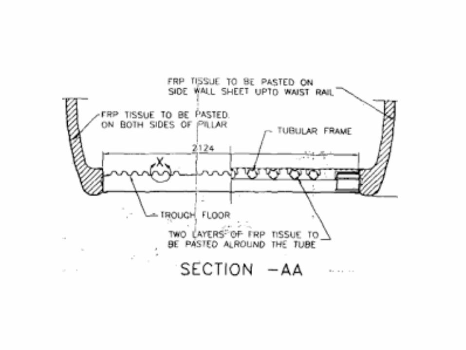
Interior partitions & Doors
• Inter partitions between the coupe’s
• Doorway partitions
• Lavatory partitions with water tank ceiling construction
• Shell doors
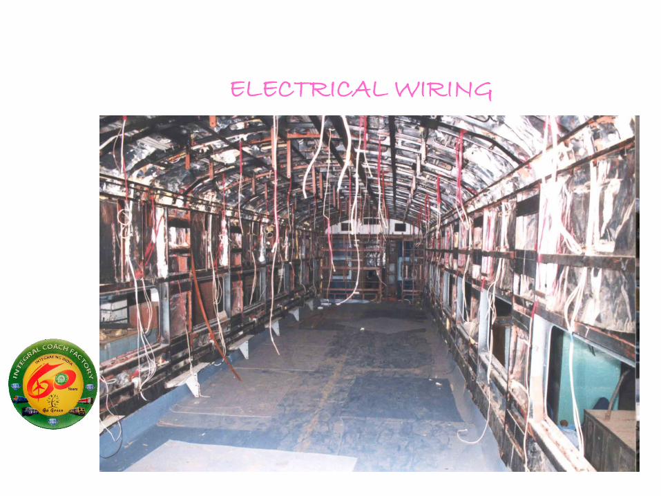
ELECTRICAL WIRING

DESIGN FEATURES
• Light weight integral design
• Hollow girders from the point of view of strength and utilization of material
• Reduction in tare weight by utilizing stressed skin concept and by use of low alloy fittings

• Stressed Skin Concept:
Type of complex structure involving curves and bendings, where the outer skin combines with a frame to produce a sound, strong, bent, curved structure.
DESIGN FEATURES

• Anti-telescopic structure at the end walls to avoid telescoping of adjacent coaches and to absorb major part of the collision energy
• Shell is made of frame work of series of hoops, consisting of floor cross beams, body side pillars and roof carlines located transversely.
DESIGN FEATURES

• These hoops are connected by sole bars, waist rails, light rails, cant rails, purlines and L- stiffeners longitudinally
• Frame work is sheathed all over by 2mm thick corten steel on the side walls & end walls and 1.6mm thick corten steel sheet on the roof.
• Under frame acts as support for mounting equipment like brake cylinders, DV, BP & FP pipes, auxiliary reservoirs, control reservoirs, etc. Air conditioning equipment, battery boxes, under slung water tank, etc.
DESIGN FEATURES

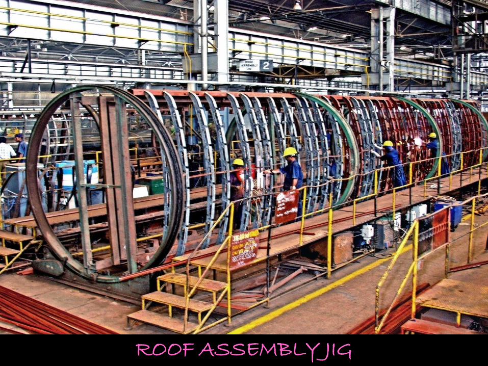
• Corrugated sheets for the trough floor to form part of the tubular construction and to absorb buffing forces
• Trough floor is provided between the sole bars and running over the length between the head stocks of the under frame
• Below the lavatory, tubular construction is provided in place of trough floor to avoid corrosion because of seepage of water.
DESIGN FEATURES
• Side bearer loading. Center pivot is free from vertical loading.
• Good riding quality. Items contributing for good
riding quality are • Coil springs • Guide and dash pot arrangement • Self aligned spherical roller bearing • Vertical shock absorbers • Silent blocks • Anchor links • Equalising devices
DESIGN FEATURES
• Camber setting:
Camber is the negative deflection of underframe given intensionally to compensate the sagging of underframe when it is fully loaded, so that the underframe can remain straight even after fully loaded.
DESIGN FEATURES

• Spot Heating: Heating and cooling of side wall and end wall
sheets to impart strength is called spot heating.
By heating and cooling, the material at that points gets shrinked and will be stretching the sheets towards the center of the heated spot.
As these spots bulge in the center, will be flattened by hammering.
DESIGN FEATURES

COACH OVERALL DIMENSIONS