CONSTRUCTING A HIGH POWER SINGLE-MODE FIBER...
50
CONSTRUCTING A HIGH POWER SINGLE-MODE FIBER LASER by COLIN DIEHL A THESIS Presented to the Department of Physics and the Robert D. Clark Honors College in partial fulfillment of the requirements for the degree of Bachelor of Science June 2014
Transcript of CONSTRUCTING A HIGH POWER SINGLE-MODE FIBER...

CONSTRUCTING A HIGH POWER SINGLE-MODE FIBER
LASER
by
COLIN DIEHL
A THESIS
Presented to the Department of Physics
and the Robert D. Clark Honors College
in partial fulfillment of the requirements for the degree of
Bachelor of Science
June 2014
ii
An Abstract of the Thesis of
Colin Diehl for the degree of Bachelor of Science
in the Department of Physics to be taken June 2014
Title: Constructing a High Power Single-Mode Fiber Laser
Approved: _______________________________________
Professor Stephen Gregory
A high power double-clad Er-Yb doped fiber laser is constructed and
characterized. The fiber is cladding pumped by a 10 W 975 nm laser diode, and later by
a 10 W 915 nm laser diode. The fiber laser generates up to 1.38 W of continuous wave
output power at 1550 nm, tunable up to 1560 nm, with a linewidth near 0.1 nm and a
slope efficiency of 15%. The fundamentals of laser physics and fiber optics are
discussed, as well as the theory behind single-mode, multimode, double-clad, and Er-
Yb co-doped fiber.

iii
Acknowledgements
I would like to thank Professor Gregory and Bryan Boggs for all their help and
guidance over the past year. As well, I’d like to thank them both for steering me toward
a career in optics, a career path I hadn’t considered before last year, but one I’m very
optimistic about now. I would also like to thank Professor Hunt for agreeing to serve as
my CHC Representative on such short notice. Finally, I’d like to thank my parents for
all their support throughout the years. I’m extremely grateful for all the support I’ve
received from so many people.

iv
Table of Contents
Introduction 1
What is a Laser? 1
Laser Construction 3
Optical Fiber 5
Single-Mode and Multimode Fiber 6
Double-Clad Fiber 8
Erbium-Ytterbium Co-Doped Fiber 9
Pump Laser 11
Controlling the Pump Laser Diode 12
Optical Fiber Connections 15
Experimental Setup 16
Experimental Results 18
Low Power Experimental Setup 20
Refined Experimental Setup 22
Mode Scrambling 24
Experimental Results 26
Conclusion 30
Appendix A: Python Code 31
Appendix B: Arduino Code 42
Appendix C: Parts Used 44
Bibliography 45

v
List of Figures
Fig. 1: Stimulated Emission 3
Fig. 2: Optical Fiber 6
Fig. 3: Single-Mode and Multimode Fibers 7
Fig. 4: Double-Clad Fiber 8
Fig. 5: Attenuation in Silica Fibers 9
Fig. 6: Erbium-Ytterbium Energy Levels 10
Fig. 7: Arduino Control Circuit Diagram 12
Fig. 8: Python GUI 14
Fig. 9: Experimental Setup 16
Fig. 10: 1550 nm Output Power vs. Launched 975 nm Pump Power up to 10 W 18
Fig. 11: 1550 nm Output Power vs. Launched 975 nm Pump Power up to 2 W 20
Fig. 12: Refined Experimental Setup 22
Fig. 13: Optimized Mode Scrambling Geometry 25
Fig. 14: 1550 nm Output Power vs. Launched 915 nm Pump Power up to 10 W 26
Fig. 15: Absorption and Emission Spectra of Yb-Doped Fiber 27
Fig. 16: 1550 nm Output Power vs. Output Coupling Ratio 28
Fig. 17: Output Spectrum 29

Introduction
High power lasers in the 1550 nanometer wavelength range have attracted
considerable interest in recent years due to their potential applications in
communications, range finding, and medical surgery. Fiber lasers in particular have
received interest because of their efficiency, cost, and reliability. However, for years
fiber lasers have been limited to either high beam quality single-mode fibers or high
power multimode fibers. But the recent development of cladding pumped double-clad
fibers has allowed the construction of high power single-mode fiber lasers, which offer
the unique combination of high power, high efficiency, high beam quality, and high
reliability.
This work aims to explain the fundamental theories behind laser physics and
fiber optics so that they may be understood by anyone. The intricacies of double-clad
fiber and the interactions between erbium and ytterbium are explored so that the design
and construction process of the fiber laser may be better understood. Finally,
experimental data on a high power single-mode fiber laser is presented.
What is a Laser?
The term laser was first coined by physicist Gordon Gould in 1957, as an
acronym for light amplification by stimulated emission of radiation. Although the
original meaning denotes a principle of operation, the term is now widely used to
describe any device that generates light under this principle. While light usually refers
only to the visible region of the electromagnetic spectrum, the light produced by a laser
can refer to infrared light, visible light, ultraviolet light, x-rays, or even gamma rays.
2
Similar devices that generate microwaves or radio waves are called masers, derived
from the acronym for microwave amplification by stimulated emission of radiation.
While there are many different types of lasers with a wide range of frequencies, they all
function under the principle of stimulated emission, first theorized by Albert Einstein in
1917 [1].
In the classical view of physics, the energy of an electron orbiting an atomic
nucleus is greater for orbits further from the nucleus of an atom. However, quantum
mechanical effects force electrons to take on discrete positions in orbitals, with specific
energy levels. When a photon excites an electron, the electron absorbs the energy from
the photon and transitions from its initial ground state to a higher energy excited state.
The energy difference between these orbitals is identical to the energy of the photon,
which is proportional to its frequency. The electron will not remain in the excited state
forever, and after some time, the electron will spontaneously decay back into a lower
energy level, releasing energy in the form of a photon, emitted in a random direction
with a random phase. When such an electron decays without external influence, the
process is called spontaneous emission. However, it is also possible for the photon
emission to be stimulated by an incoming photon. If an incident photon with suitable
energy interacts with an electron in an excited state, the electron will immediately
transition to a lower energy level by emitting a photon in the same direction as the
incident photon, with the same energy, wavelength, phase, and polarization [2]. This
process is called stimulated emission, and unlike absorption, during which the incident
photon is destroyed, a second photon is produced and the incoming light is amplified by
the stimulated emission of radiation (Fig. 1).

3
Fig. 1: Stimulated Emission
(a) Before emission, the electron is in the excited state. (b) During emission, the
incident photon causes the electron to transition to the ground state by emitting a
photon. (c) After emission, the emitted photon propagates in the same direction with
the same frequency and phase as the incident photon, amplifying the light.
Laser Construction
A laser is constructed from three principal parts: an energy source, a gain
medium, and a laser cavity. Each part fulfills an important requirement for stimulated
emission. The energy source, often referred to as the energy pump or pump source,
provides the energy to the laser system by exciting the atoms in the gain medium into an
excited state. Laser amplification requires that the pump source must be powerful
enough to create a population inversion of the gain medium, meaning there must be a
greater number of atoms in the excited state of the gain medium than in the ground
state. Common examples of energy sources include electrical currents, flashlamps, and
even the light from another laser.
The gain medium is the source of optical gain in the laser. The atoms within the
gain medium are excited by the pump source, and caused to emit photons both by
stimulated and spontaneous emission. The energy levels of the gain medium determine

4
the wavelength of the laser, and the type of gain medium determines the type of pump
source. There are thousands of different types of gain media, in the form of solids,
liquids, and gases.
The laser cavity provides the final component necessary for lasing: feedback.
The laser cavity provides the incident light to the excited atoms in the gain medium
allowing stimulated emission. The laser cavity also commonly serves as the output
coupler, allowing some percentage of the light to leave the system while returning the
remainder as feedback. A laser cavity can simply be a pair of parallel, partially
reflective mirrors surrounding a gain medium. While some of the light reflects off the
mirror providing the gain medium with feedback, the other portion transmits through
the mirror as the output of the laser.
A laser functions by first supplying the gain medium with energy. The pump
source excites an atom in the gain medium to spontaneously emit an initial photon. The
laser cavity then returns this photon as feedback to the gain medium where it interacts
with another atom excited by the pump source, causing stimulated emission. The
emitted photon propagates in the same direction and with the same phase and
wavelength as the original photon. The process continues, creating a chain reaction as
the light amplifies, increasing the power of the laser. The output coupler transmits some
of the light out as the output of the laser, and provides the rest of the light as feedback to
the gain medium where it causes further stimulated emission. The output power of the
laser will continue to rise until it reaches a point where either the pump source cannot
provide any additional energy, or the gain medium cannot be excited any further. At this

5
point, usually after only a few milliseconds, the output power will level off and remain
constant, producing a continuous wave (CW) laser.
Optical Fiber
In a vacuum like outer space, light travels at about 300,000 kilometers (186,000
miles) per second. But light travels at different speeds in different materials. The
refractive index of a material denotes the speed light can travel through it, the faster
light can travel, the lower the refractive index. A vacuum therefore has the lowest
refractive index of 1, while air has a refractive index of 1.0003 and water has a
refractive index of 1.33. When light passes between two materials with different
refractive indices, the light will refract, or bend. This is why a straight object placed
partially in water will appear to bend at the water’s surface. When light travels from a
higher refractive index material to a lower refractive index material at a steep angle,
rather than refracting, all of the light will be reflected. This effect is called total internal
reflection, and it is what allows optical fibers to function.
Optical fiber is a flexible, transparent fiber made of glass or plastic which acts
like a light pipe, transmitting light between the two ends of the fiber. Optical fiber has a
central core which is embedded in a cladding of slightly lower refractive index. Thus,
light traveling down the core will reflect off the core-cladding boundary and be guided
through the core without refracting into the cladding (Fig. 2).

6
Fig. 2: Optical Fiber
Light traveling through the core of the fiber is totally internally reflected by the
boundary of the cladding, guiding the light down the length of the fiber.
Single-Mode and Multimode Fiber
When light propagates through the core of an optical fiber, it can only do so in a
discrete set of transverse modes. Each of these modes corresponds to a specific angle at
which the light travels down the length of the fiber. These modes are independent of
wavelength, so light of different wavelengths can propagate in the same mode. The
number of transverse modes allowed in the core is however dependent on the type of
optical fiber.
Optical fiber comes in two common types: multimode and single-mode.
Multimode fiber has a large core that supports multiple modes, while single-mode fiber
has a small core which can only support a single propagation mode. The core of a
typical single-mode fiber has a diameter of only 6 μm (micrometers), which prohibits
higher-order modes from entering the core, and only supports the fundamental mode
which propagates directly down the fiber. A typical multimode core has a diameter of
50 μm which supports the fundamental mode and multiple higher-order modes (Fig. 3).

7
Fig. 3: Single-Mode and Multimode Fibers
The single-mode core only allows the fundamental mode to propagate directly down the
length of the fiber, while the larger multimode core allows several modes to propagate
down the fiber at different angles. Both fibers are drawn to scale.
Single-mode and multimode fibers both have their own advantages and
disadvantages. A fiber laser constructed with single-mode fiber can produce very high
output beam quality, but this requires a single-mode pump laser, which is much more
expensive and less powerful than a multimode source. Using multimode fiber would
allow for multimode pumping, but multimode fibers generally lead to poor beam quality
and have higher propagation losses through the core. Single-mode fiber sacrifices power
for beam quality, and multimode fiber sacrifices beam quality for power. Neither allow
for a high power fiber laser with high beam quality. However, this dilemma was
resolved with the advent of double-clad fiber.
8
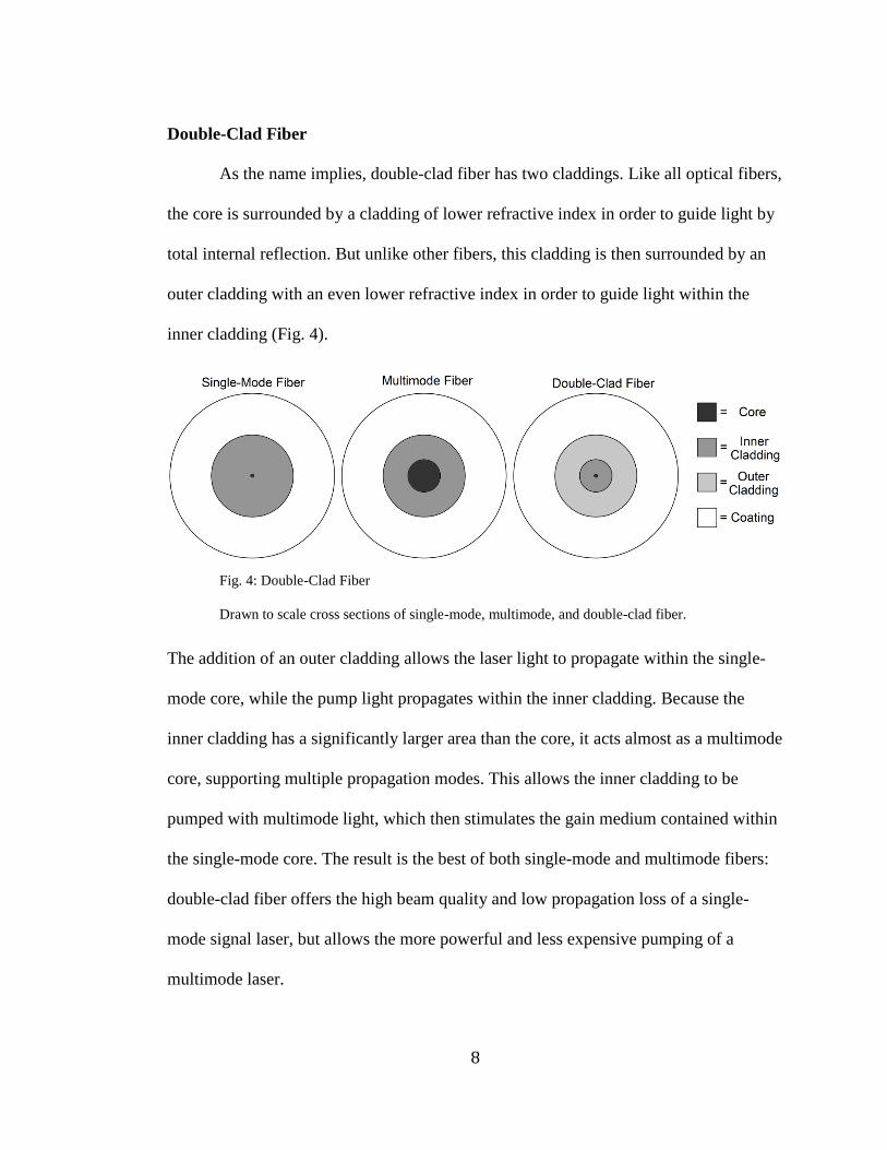
Double-Clad Fiber
As the name implies, double-clad fiber has two claddings. Like all optical fibers,
the core is surrounded by a cladding of lower refractive index in order to guide light by
total internal reflection. But unlike other fibers, this cladding is then surrounded by an
outer cladding with an even lower refractive index in order to guide light within the
inner cladding (Fig. 4).
Fig. 4: Double-Clad Fiber
Drawn to scale cross sections of single-mode, multimode, and double-clad fiber.
The addition of an outer cladding allows the laser light to propagate within the single-
mode core, while the pump light propagates within the inner cladding. Because the
inner cladding has a significantly larger area than the core, it acts almost as a multimode
core, supporting multiple propagation modes. This allows the inner cladding to be
pumped with multimode light, which then stimulates the gain medium contained within
the single-mode core. The result is the best of both single-mode and multimode fibers:
double-clad fiber offers the high beam quality and low propagation loss of a single-
mode signal laser, but allows the more powerful and less expensive pumping of a
multimode laser.

9
Erbium-Ytterbium Co-Doped Fiber
In order to utilize optical fiber as a gain medium, the core of the fiber is doped
with rare earth elements like erbium, ytterbium, neodymium, or thulium. The active
fiber is then optically pumped by a laser which excites the dopant material. Erbium-
doped fibers have become especially important, as the most common optical amplifier
used in fiber optic communications. When Er3+
ions are optically pumped at around 975
nm, they radiate light with a wavelength near 1550 nm, which attenuates least in typical
silica fibers (Fig. 5) [3].
Fig. 5: Attenuation in Silica Fibers
Attenuation in silica fibers is strongly dependent on wavelength. Silica has a strong
absorption band in the mid-infrared region due to molecular vibrations. Rayleigh
scattering, caused by random inconsistencies in the glass, causes shorter wavelengths to
scatter more than longer wavelengths. Impurities, caused by water vapor dissolved in
the glass, cause an OH absorption band. The result is a local minimum at 1.3μm and an
absolute minimum at 1.55 μm [3].
While erbium emits the desired wavelength, it only allows for efficient lasing in single-
mode systems. For cladding pumped double-clad systems, the absorption of erbium is

10
impractically low [4,5]. However, by co-doping the fiber with erbium and ytterbium,
absorption can be increased significantly.
The core of the double-clad fiber is co-doped with Er3+
and Yb3+
, with a much
greater concentration of ytterbium in order to improve pump absorption [6]. Ytterbium
has only one excited state within reach from the ground state with near-infrared light,
and both states have wide bands, allowing ytterbium to efficiently absorb light from a
wide range of 800 nm to 1100 nm [7] (Fig. 6).
Fig. 6: Erbium-Ytterbium Energy Levels
The energy levels of erbium-ytterbium co-doped fiber. Co-doping the core with
ytterbium not only increases efficiency, but also allows efficient pumping with 915 nm
light as well.
Pumping the Er-Yb doped fiber (EYDF) with 915 nm or 975 nm light predominately
excites the ytterbium in the core into the 2F5/2 excited state. From there, the ytterbium
non-radiatively transfers energy to the erbium ions through the dipole-dipole resonant
interaction between closely located ions [8]. This energy transfer puts the erbium into
the same 4I11/2 excited state as if it were pumped with 975 nm light. The erbium then
decays to the lower 4I13/2 excited state through a non-radiative multi-phonon transition,
11
decaying by emitting vibrational energy. From this state, the erbium will at first
spontaneously decay to the 4I15/2 ground state, emitting a 1550 nm photon. But as the
laser cavity provides feedback, incident photons will cause the erbium in the 4I13/2 level
to decay by stimulated emission, creating a 1550 nm laser.
Pump Laser
To excite the EYDF, the double-clad fiber is cladding pumped by a laser diode.
A laser diode is an electrically pumped semiconductor laser in which the gain is
generated by an electric current flowing through a semiconductor diode junction similar
to those found in light emitting diodes. Laser diodes are one of the most efficient and
dependable laser types, and are the most common type of laser produced.
The multimode pump laser diode operates at 975 nm with a maximum output of
10 W. The laser diode has a conversion efficiency of 45%, so when it is driven at full
power with 12 A and 1.9 V, 55% of the input electrical power, 12.54 W, is given off as
waste heat. A laser diode can easily be damaged by heat, so it is cooled by a
thermoelectric cooler (TEC). When a voltage is applied across a TEC, a temperature
difference will build up between the two sides, cooling one side and heating the other.
The laser diode is then mounted on the cool side along with a thermistor, a resistor with
variable resistance depending on the temperature. This allows a temperature controller
to monitor the temperature and vary the current to keep the temperature constant,
protecting the laser diode.

12
Controlling the Pump Laser Diode
The laser diode is powered by a laser diode driver, which produces up to 15 A
when supplied with a 0-10 V control signal. To generate the signal, I decided to create a
graphical user interface (GUI) that would allow the laser diode output power to be set
by a computer. I chose to use the Python programming language because of its simple
syntax, accessibility, and its multitude of available modules. Using the module PySerial
allows Python to easily communicate with an Arduino Duemilanove, a microcontroller,
which outputs the control signal for the laser diode driver.
In order to drive the laser diode with its maximum rated current of 12 A, the
laser diode driver needs a control signal of 8 V. However, the Duemilanove only has
digital outputs, which can be set to 0 or 5 V. Therefore, I designed a circuit with an 8-
bit digital-to-analog converter (DAC) to set the output voltage (Fig. 7).
Fig. 7: Arduino Control Circuit Diagram
The control circuit which enables the Arduino to control and monitor the laser diode
driver. The DAC, along with the accompanying op-amp and inverting amplifier, allows
the Arduino’s digital outputs to set the analog control signal. The other inverting
amplifiers allow the Arduino to monitor the laser diode driver’s current.

13
Dependent on which digital inputs are set to high, the DAC will output a current
corresponding to 256 different possible voltages varying from zero to the reference
voltage, which is set to 8 V using a 15 V power supply and a simple voltage divider.
The DAC’s output currents are easily converted to the correct voltage using an op-amp
with negative feedback from the DAC’s internal feedback resistor and an inverting
amplifier with -1 gain.
As well as setting the output current, the laser diode driver also outputs a 0-2 V
voltage monitor signal and a 0-10 V current monitor signal. The Arduino simply
measures the voltage monitor signal using a built in analog-to-digital converter (ADC),
however the Arduino can only measure voltages up to 5 V. Because of the input
impedance of the Arduino, a simple resistive voltage divider could not be used to
reduce the current monitor voltage. Instead, two non-inverting amplifiers were used:
one with –1/2 gain, and the other with -1 gain. The Arduino, control circuit, and the
diode driver were then all built into a box along with the power supply, cooling fan,
interlock switch, and a USB-B port to connect to a computer.
With the control circuit, the Arduino can now control and monitor the laser
diode driver. The Python GUI creates a window allowing the laser diode to be
controlled completely from the computer, as well as monitoring the current and voltage
set by the diode driver (Fig. 8).

14
Fig. 8: Python GUI
The graphical user interface which controls and monitors the laser diode. The GUI also
enables the laser diode and monitors whether the interlock switch is turned on or off.
The Python GUI can either set the current directly, or select the output power using a
linear fit based on the measured output of the laser. The Python code then
communicates with the Arduino, which interprets the commands, and sets the output
accordingly. To protect the laser diode, the Arduino slowly ramps up the current to
avoid any voltage or current spikes. To protect those operating the laser, the laser diode
driver will only supply a current when it has been enabled from the GUI, and the
interlock switch on the box has been turned on. The Python and Arduino codes used can
be found in Appendices A and B, respectively.

15
Optical Fiber Connections
In order to transmit light from one optical fiber into another, the optical fiber
ends must be connected so that light may pass from one core to another without
significant loss. This can be done with either optical fiber connectors or fusion splices,
each having their own advantages and disadvantages. Fusion splicing joins the two fiber
ends using heat, creating one continuous fiber. Fusion splices provide the best
connections with the lowest amount of loss, but splices are permanent and connections
cannot be changed without breaking the fiber. The non-permanent method of
connecting fibers is using optical fiber connectors. Using ferrule connectors (FC) allows
for optical components to easily be switch or removed, but causes much more loss.
Ferrule connectors come in two variants: physical contact (PC) and angled physical
contact (APC). In either case, the fiber is stripped of its coating, embedded in the
ceramic ferrule, and epoxied into place. The fiber end is then polished to produce a
rounded surface using lapping film, an ultrafine abrasive material which functions like
sandpaper. While flat FC/PC connectors typically have lower insertion loss, FC/APC
connectors severely reduce back-reflections, as any light which reflects off the angled
polished end leaks into the cladding of the fiber. Two connectors are then attached
using a mating sleeve which aligns the cores, holds the connectors in place, and
properly aligns the angled ends of FC/APC connectors. While fusion splices provide
less loss, I elected to use FC/APC connectors wherever possible so that parts may be
reused in the future.

16
Experimental Setup
The experimental setup consists of a 1.5 m long Er-Yb doped fiber pumped by a
10 W 975 nm multimode laser diode (Fig. 9).
Fig. 9: Experimental Setup
Double-clad Er-Yb doped fiber laser pumped by a 975 nm laser diode.
The pump laser is launched into the double-clad fiber by a wavelength division
multiplexer (WDM), which combines 1550 nm light into the core and 975 nm light into
the inner cladding. The launch efficiency was measured to be 97% at the double-clad
output of the WDM. The pump 975 nm light excites the EYDF, which spontaneously
emits 1550 nm light in the single-mode core. The 1550 nm light is guided through the
single-mode core to the output coupler, while the excess 975 nm light is dumped out of

17
the cladding and absorbed as heat by the fusion splice. The output coupler extracts 90%
of the 1550 nm signal light as the output of the laser, while 10% remains in the ring
laser as feedback. The optical isolator ensures that only 1550 nm light propagating in
the clockwise direction will be amplified, reducing mode competition within the laser.
The WDM then combines the 1550 nm light back into the core of the double-clad fiber
where it will be amplified by stimulated emission.
The double-clad fiber used in the experimental setup does not actually have two
glass claddings. Instead, the fiber is identical to a single-mode fiber, except for the
coating, which is a low index polymer that acts as the outer cladding. This saves a
considerable amount of money during the fabrication process, allowing the
manufacturer to use the same fabrication process as single-mode fiber. As well, the
fiber acts identically to a standard double-clad fiber. However, when the fiber is
connectorized, the stripped fiber is embedded in high refractive index epoxy. Rather
than reflecting, the pump light in the cladding is then transmitted into the epoxy, where
the high power light melts the epoxy, breaking the fiber at the connector. To avoid this,
the EYDF was fusion spliced to the double-clad pigtail of the WDM and to the single-
mode input of the output coupler. To protect the splices, they were covered with the
hollow metal tip from a fiber optics epoxy syringe, beneath a standard splice protector.
The syringe tips prevented the epoxy in the splice protectors from contacting the bare
fiber, enclosing the inner cladding with air to act as the outer cladding. As well, the
metal syringe tips acted as a heat sink for any scattered pump light. The pump laser was
FC-PC connectorized to the multimode pigtail of the WDM simply because it came pre-

18
connectorized by the manufacturer. All other fiber connections were made with FC-
APC connectors.
Experimental Results
Fig. 10 shows the measured 1550 nm output power versus the launched 975 nm
pump power.
Fig. 10: 1550 nm Output Power vs. Launched 975 nm Pump Power up to 10 W
Evolution of the output power as a function of pump power, for 1.5 m of EYDF
pumped with 975 nm light.
The laser has a threshold pump power of 0.31 W, with an output of 2.853 mW. The
maximum achieved output power was 1.055 W with 7.055 W of pump power.
Interestingly, increasing the pump power above 7.055 W actually resulted in a loss of
output power, with an output of only 0.743 W with 10.448 W of pump power. I
originally theorized that the laser was reaching saturation near 7 W, and some loss
mechanism was contributing to the loss of power.
In an optically pumped laser, only the absorbed pump light excites the gain
medium. Increasing the pump power will increase the amount of ions in the excited

19
state, from where they can emit and amplify light. However, it will also decrease the
amount of ions in the ground state, from where they absorb the pump light. As the pump
power increases, the output power of the laser will increase, but the gain will decrease,
as there are less ions available to absorb light. At some point, the laser will reach
saturation and there will be no more available ions in the ground state to absorb the
pump light. Pumping the gain medium with additional power will result in no additional
output power. When a gain medium approaches saturation, the gain will slowly
decrease with additional pump power, until it completely saturates and reaches zero.
However, as we can see in Fig. 10, the gain sharply increases near 4 W of pump power,
then decreases sharply near 6 W of pump power. This led me to believe the power loss
may have been due to another cause, such as the modal structure of the diode laser.
Multimode lasers emit light in a combination of higher-order modes. As the
power of the laser changes, it is possible for its modal structure to change as well. This
can create problems with absorption in double-clad fiber, where only the core is actively
doped, and only the light which overlaps the core of the double-clad fiber can be
absorbed by the gain medium. If the modal structure of the pump laser devolved to
produce helical modes at higher powers, the light would only propagate in the cladding
around the core, severely reducing the output power of the laser.
To test my hypothesis, I replaced the 1.5 m piece of EYDF with a 3 m length. If
the reduction in power was due to saturation, extending the gain medium would
increase the pump power needed for saturation, causing the maximum output to occur at
a higher pump power. If the reduction in power was due to the degenerative modal
structure of the pump laser, the peak output would remain near 7 W of pump power.

20
Measuring the output, I observed the maximum 1550 nm light to peak near 7.3 W of
pump power, supporting the theory that the pump laser’s devolving modal structure
caused the drop in power. However, before any official measurements were taken, the
pump laser burned out.
Low Power Experimental Setup
Without another 10 W 975 nm laser diode, two 1 W 975 nm laser diodes were
used to pump the EYDF. The pump lasers were FC-PC connectorized to the multimode
pigtails of the WDM. Fig. 11 shows the measured 1550 nm output power versus the
launched 975 nm pump power.
Fig. 11: 1550 nm Output Power vs. Launched 975 nm Pump Power up to 2 W
Evolution of the output power as a function of pump power, for 3 m of EYDF pumped
with 975 nm light.
The maximum output power measured was 297 mW at 2 W of pump power. Unlike the
previous setup, the output power increased linearly with a slope efficiency of 18%.
When pumping near threshold, I observed through an IR (infrared) viewer that the light
21
in the fusion splice pulsed. Running the laser into a photodiode, self-pulsing of the laser
was measured with a frequency near 48 kHz.
At low pump powers, when the pump is not able to maintain a complete
population inversion, the gain medium will act as a saturable absorber, due to the
formation of erbium ion pairs. Co-doping the gain medium with ytterbium reduces ion
pair formation, but it does not eliminate it [9]. Exciting the erbium ion pairs causes a
depletion of the ground state. The excited erbium ion pairs must decay back into the
ground state before they will absorb again, causing the laser to pulse at the relaxation
frequency of the population inversion. The frequency of the pulsing can be increased by
raising the pump power, replenishing the population inversion at a faster rate [10].
Increasing the pump power above 0.55 W completely suppresses all self-pulsing,
allowing stable continuous-wave operation of the laser.

22
Refined Experimental Setup
To improve the laser, several new components were implemented into the fiber
ring laser, including a new pump laser. The two 1 W 975 nm diodes were replaced with
a 10 W 915 nm laser diode in the refined setup (Fig. 12).
Fig. 12: Refined Experimental Setup
Double-clad Er-Yb doped fiber laser pumped by a 915 nm laser diode.
Just like before, the pump laser is launched into the inner cladding of the double-clad
fiber by the WDM. The double-clad pigtail of the WDM is fusion spliced to the active
double-clad fiber without a splice protector. Instead, the splice is left bare to prevent the
pump light from being absorbed as heat. The fusion splice is then mechanically held by
a hollow disc to completely surround the bare splice with air. The pump 915 nm light
then excites the Er-Yb doped core of the double-clad fiber, causing the spontaneous

23
emission of 1550 nm light in the core. The EYDF is then fusion spliced to another
WDM. This splice too is left unprotected and held isolated in air. The WDM separates
the 1550 nm light into the core of the single-mode fiber, and dumps the excess 915 nm
pump light out of the system. The output coupler extracts some percentage of the signal
light as the output of the laser, while the remaining light remains in the laser as
feedback. The light travels into the optical circulator, which only allows light to travel
through its ports in one direction. The light enters port 1 of the circulator and exits out
of port 2, into the fiber Bragg grating (FBG). A Bragg grating is a selective reflector,
which reflects particular wavelengths of light and transmits all others. The Bragg
grating is constructed into the core of a short segment of optical fiber, and serves to
reduce the bandwidth of the laser by only allowing a small range of wavelengths to be
amplified. Light outside this range transmits through the Bragg grating and is dumped
out of the system, while light within the range is reflected back into the optical
circulator. The circulator transmits the reflected light into the single-mode pigtail of the
WDM, which combines the light back into the core of the double-clad fiber where it
will be amplified by stimulated emission.
24
Mode Scrambling
The efficiency of the fiber laser depends largely on the coupling of the pump
light from the inner cladding to the Er-Yb doped core. However, in double-clad fibers,
the pump light can propagate in the so-called doughnut mode, in which light propagate
in a circular ring, but not in the center. The doughnut mode has a very poor overlap with
the centered core, resulting in reduced absorption of the pump light. Therefore, for
efficient absorption of the pump light, the pump modes must be scrambled to increase
the core overlap.
To improve the pump absorption, I investigated various mode scrambling
techniques. Simply winding the EYDF in various shapes with small radius bends
disturbs the mode structures of the pump, increasing the overlap of the pump modes
with the core. The Er-Yb doped fiber is fusion spliced to the WDM and then wrapped
around a series of optics posts to create different mode scrambling geometries. The
EYDF was then pumped at a low power to excite the gain medium, but prevent a
population inversion. Absorbed 915 nm light causes the EYDF to spontaneously emit in
a random direction. The opposite end of the EYDF is cleaved and placed into a power
meter, which measures the remaining 915 nm light not absorbed by the EYDF. This is
not a definitive measure of the absorption; even at low power and without feedback
there will still be some 1550 nm light measured by the power meter. However, the
measurement should prove a useful relative measurement of various mode scrambling
geometries.
Without any mode scrambling, the EYDF absorbed 58% of the 915 nm pump
light. Bending the EYDF into a circle and a figure eight increased the absorption to 62%

25
and 63%, respectively. A kidney shaped geometry has been shown to maximize
absorption, by combining fiber sections of different radii and lengths to perform mode
mixing at the points where the curvature changes [11]. With a kidney shaped mode
scrambler, the absorption increased to 64%. By varying the dimensions of the kidney
shaped mode scrambler and observing how the absorption responded, I increased the
absorption to 71% using the optimized geometry shown in Fig. 13.
Fig. 13: Optimized Mode Scrambling Geometry
Combining fiber sections with different lengths and radii scrambles the modes at the
curvature changes, increasing the pump light absorption in the following piece of fiber.

26
Experimental Results
The output power of the laser was measured for EYDF lengths of 3 m, 4 m, and
5 m. The output power was optimized using different output couplers for each length.
Fig. 14 shows the output power of the laser versus the launched pump power for the
various EYDF lengths.
Fig. 14: 1550 nm Output Power vs. Launched 915 nm Pump Power up to 10 W
Evolution of the output power as a function of pump power, for 3 m, 4 m, and 5 m of
EYDF pumped with 915 nm light.
The maximum measured output power was 1.384 W for the 5 m long EYDF with 98%
output at 10 W. Extending the length of EYDF improved the slope efficiency of the
laser from 9.76% for 3 m of EYDF, to 12.74% for 4 m of EYDF, to 15.22% for 5 m of
EYDF. The greater length of EYDF also increased the output power of the laser
because the excess unabsorbed pump light was absorbed more by the longer fibers.
Even with 5 m of EYDF, the upper limit of the theoretical absorption of 915 nm light in
the inner cladding is only 6.45 W. Even at its peak efficiency, the 915 nm pumped fiber

27
laser is still less efficient than the 975 nm pumped laser due to the absorption of Yb3+
(Fig. 15) [12].
Fig. 15: Absorption and Emission Spectra of Yb-Doped Fiber
Yb-doped fiber exhibits a primary absorption peak near 975 nm with a small linewidth,
and a broad absorption peak near 915 nm.
The smaller absorption peak near 915 nm for ytterbium limits the amount of absorbed
pump light, and reduces the slope efficiency of the 915 nm pumped fiber laser.
Measuring the absorption of the mode scrambled EYDF as I did before, the 5 m of
EYDF absorbed 71% of the 915 nm pump laser. Pumping the EYDF with the same
amount of 975 nm pump light, the 5 m of EYDF absorbed 96% of the pump light.
While the different mode structures of the two pump lasers possibly contributed to the
difference in absorption, it is evident that the reduced slope efficiency of the 915 nm
pumped fiber laser is due to the reduced absorption of ytterbium at 915 nm.
To determine the optimum output coupling ratio for the fiber laser, six fiber
couplers were used to extract the power from the laser cavity in 11 different output

28
ratios. Fig. 16 shows the output power of the laser versus the output coupling ratio for
the 3 m, 4 m, and 5 m lengths of EYDF pumped at 10 W.
Fig. 16: 1550 nm Output Power vs. Output Coupling Ratio
Evolution of the output power as a function of output coupling ratio, for 3 m, 4 m, and
5 m of EYDF pumped with 10 W of 915 nm light. The small changes in power for the
higher coupling ratios are likely caused by the inconsistent polish quality of the FC-
APC connectors.
As is expected in long fiber lasers, higher powers are obtained for the higher output
coupling ratios. For long fiber lasers, the single-pass gain is great, requiring a high
output coupling ratio for optimized power. On the other hand, for short fiber lasers, the
low single-pass gain has to be compensated with high feedback percentages in order to
function [13]. Output coupling optimization follows similar rules for all lasers. For
high-gain lasers, the output power can remain fairly constant over a wide range of
output coupling ratios. While for low-gain lasers, the optimization of the output
coupling is crucial for operation [14]. As a long fiber laser and a high-gain laser, the
double-clad fiber laser does not require precise coupling optimization, as the output
power remains fairly constant from 80% to 99% output coupling.
29
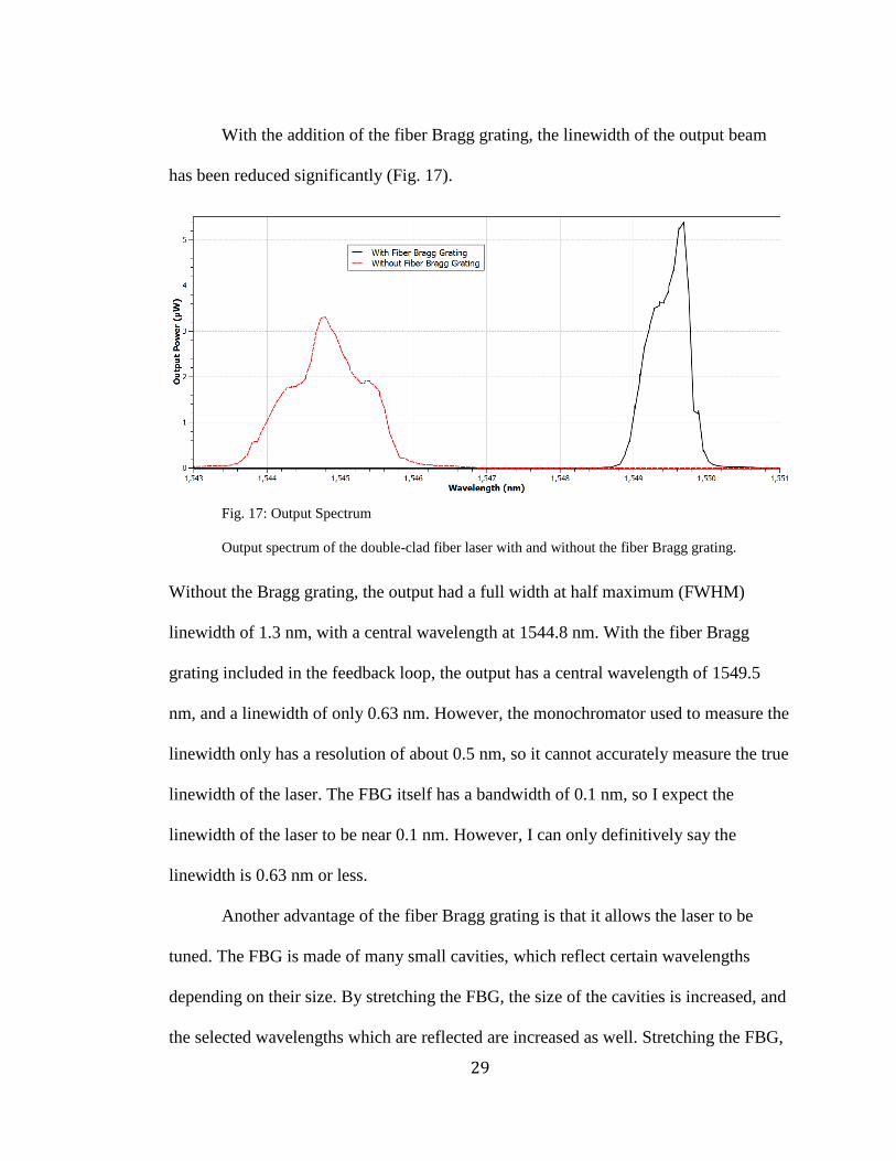
With the addition of the fiber Bragg grating, the linewidth of the output beam
has been reduced significantly (Fig. 17).
Fig. 17: Output Spectrum
Output spectrum of the double-clad fiber laser with and without the fiber Bragg grating.
Without the Bragg grating, the output had a full width at half maximum (FWHM)
linewidth of 1.3 nm, with a central wavelength at 1544.8 nm. With the fiber Bragg
grating included in the feedback loop, the output has a central wavelength of 1549.5
nm, and a linewidth of only 0.63 nm. However, the monochromator used to measure the
linewidth only has a resolution of about 0.5 nm, so it cannot accurately measure the true
linewidth of the laser. The FBG itself has a bandwidth of 0.1 nm, so I expect the
linewidth of the laser to be near 0.1 nm. However, I can only definitively say the
linewidth is 0.63 nm or less.
Another advantage of the fiber Bragg grating is that it allows the laser to be
tuned. The FBG is made of many small cavities, which reflect certain wavelengths
depending on their size. By stretching the FBG, the size of the cavities is increased, and
the selected wavelengths which are reflected are increased as well. Stretching the FBG,

30
the central wavelength of the laser was able to be increased and tuned within a range of
nearly 10 nm, from 1549 nm to 1559 nm.
Finally, I measured the beam quality factor (M2) of the laser. The M
2 factor is
the ratio of a beam’s diameter and divergence angle compared to that of an ideal
Gaussian beam at the same wavelength. For an ideal single-mode Gaussian beam, the
M2 value is exactly one. For multimode beams, the M
2 value will be much higher. I
measured the M2 factor of the fiber laser to be 1.10, with a beam waist of only 86 μm,
representing a very good single-mode laser.
Conclusion
In summary, I have designed and realized an all-fiber high power single-mode
fiber laser. Pumping the cladding of the Er-Yb co-doped double-clad fiber, the laser
delivers up to 1.38 W of continuous wave output at 1550 nm, tunable up to 1560 nm.
The laser has a linewidth of 0.1 nm, a slope efficiency of 15%, and a beam quality
factor (M2) of 1.10. The diode laser is controlled by computer, using a Python GUI and
an Arduino constructed for this experimental setup. The laser could be improved in the
future to deliver higher output powers by replacing the 915 nm pump laser with a 975
nm laser diode, with the use of additional pump lasers, or by simply extending the
EYDF. As well, implementing a diffraction grating or Fabry-Perot cavity into the ring
cavity could further reduced the linewidth of the laser.
31
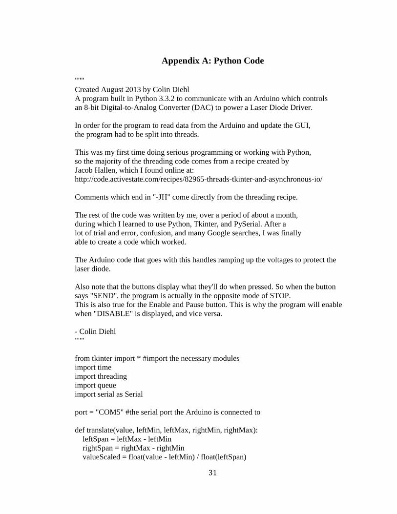
Appendix A: Python Code
"""
Created August 2013 by Colin Diehl
A program built in Python 3.3.2 to communicate with an Arduino which controls
an 8-bit Digital-to-Analog Converter (DAC) to power a Laser Diode Driver.
In order for the program to read data from the Arduino and update the GUI,
the program had to be split into threads.
This was my first time doing serious programming or working with Python,
so the majority of the threading code comes from a recipe created by
Jacob Hallen, which I found online at:
http://code.activestate.com/recipes/82965-threads-tkinter-and-asynchronous-io/
Comments which end in "-JH" come directly from the threading recipe.
The rest of the code was written by me, over a period of about a month,
during which I learned to use Python, Tkinter, and PySerial. After a
lot of trial and error, confusion, and many Google searches, I was finally
able to create a code which worked.
The Arduino code that goes with this handles ramping up the voltages to protect the
laser diode.
Also note that the buttons display what they'll do when pressed. So when the button
says "SEND", the program is actually in the opposite mode of STOP.
This is also true for the Enable and Pause button. This is why the program will enable
when "DISABLE" is displayed, and vice versa.
- Colin Diehl
"""
from tkinter import * #import the necessary modules
import time
import threading
import queue
import serial as Serial
port = "COM5" #the serial port the Arduino is connected to
def translate(value, leftMin, leftMax, rightMin, rightMax):
leftSpan = leftMax - leftMin
rightSpan = rightMax - rightMin
valueScaled = float(value - leftMin) / float(leftSpan)

32
return int(rightMin + (valueScaled * rightSpan))
#a function similar to the Arduino map function
#translates a value from one range to another
serial = Serial.Serial(port, 9600, timeout=.01)
#opens a serial port to the Arduino, with a .01 sec timeout
class GuiPart(Frame):
""" This is the main GUI class which sets up the GUI layout
and defines the functions of the buttons"""
def __init__(self, master, queue):
Frame.__init__(self,master)
self.grid()
self.queue = queue
self.create_widgets()
global default
default = self.cget('bg') #defines the default button color
def create_widgets(self):
""" This is the function that creates and places everything that
appears in the GUI"""
Label(self,
text = "Choose Entry Mode:"
).grid(row = 0, column = 0)
self.choice = StringVar()
self.choice.set("Laser Diode Power")
#radiobuttons allows the user to set the entry mode to control the DAC
Radiobutton(self,
text = "Binary",
variable = self.choice,
value = "Binary",
command = self.update_mode
).grid(row = 1, column = 0)
Radiobutton(self,
text = "Voltage",
variable = self.choice,
value = "Voltage",
command = self.update_mode
).grid(row = 1, column = 1)
Radiobutton(self,
text = "Current",
variable = self.choice,
value = "Current",
command = self.update_mode
).grid(row = 1, column = 2)
Radiobutton(self,

33
text = "Laser Diode Power",
variable = self.choice,
value = "Laser Diode Power",
command = self.update_mode
).grid(row = 1, column = 3)
#instructions for what value to enter
self.mode = Label(self)
self.mode["text"] = " Enter the desired laser diode power between 0 and 10.00 W
below: "
self.mode.grid(row = 2, column = 0, columnspan = 4, sticky = W)
#entry box for user to type in numbers
self.value = Entry(self)
self.value.grid(row=3, column=0)
#label which displays different units depending on selected entry mode
#default mode is power, so units is initially Watts
self.units = Label(self)
self.units["text"] = "W"
self.units.grid(row = 3, column = 1, sticky = W)
#Button to send entered value to Arduino
self.send=Button(self, height = 2, width = 12)
self.send["text"]= "SEND"
self.send["bd"] = 3
self.send["command"] = self.go
self.send.grid(row = 3, column = 2, rowspan = 2)
#Button to enable laser diode driver
self.enable=Button(self, height = 2, width = 12)
self.enable["text"]="ENABLE"
self.enable["bd"] = 3
self.enable["command"] = self.toggle
self.enable.grid(row = 3, column = 3, rowspan = 2)
#Button to end the program
self.end=Button(self, height = 2, width = 12)
self.end["text"]= "END"
self.end["bd"] = 3
self.end["command"] = self.quit
self.end.grid(row = 3, column = 5, rowspan = 2)
#Text box to display error messages
self.error = Text(self, width = 17, height = 1)
self.error.grid(row = 4, column = 0)
34
#Labels Arduino input
Label(self,
text = "Arduino Input: "
).grid(row = 5, column = 1)
#Arduino input text box
self.ard_read = Text(self)
self.ard_read.grid(row = 6, column = 0, rowspan = 4, columnspan = 7)
self.ard_read["width"] = 98
#Scrollbar attached to Arduino input text box
self.scroll=Scrollbar(self)
self.scroll["command"] = self.ard_read.yview
self.scroll.grid(row = 6, column = 6, rowspan = 4, columnspan = 1, sticky = 'nsew')
self.ard_read["yscrollcommand"] = self.scroll.set
#Button to pause the Arduino input
self.pause = Button(self)
self.pause["text"] = "Pause\n " + "Arduino Input"
self.pause["command"] = self.ard_pause
self.pause["bd"] = 3
self.pause.grid(row = 10, column = 0, rowspan = 2)
#Button to clear the Arduino input
self.clear = Button(self)
self.clear["text"] = "Clear\n " + "Arduino Input"
self.clear["command"] = self.empty
self.clear["bd"] = 3
self.clear.grid(row = 10, column = 1, rowspan = 2)
#Interlock on/off label
self.interlock = Label(self)
self.interlock["text"]="INTERLOCK: "
self.interlock["height"] = 4
self.interlock["width"] = 30
self.interlock.grid(row = 1, column = 7, rowspan = 3)
def ard_pause(self): #toggles between pause and update
pause_index_dict={"Pause": "Update" , "Update" : "Pause"}
pause_index[0] = pause_index_dict[pause_index[0]]
if pause_index[0] == "Pause":
self.pause["text"] = str(pause_index[0]+'\n') + ' Arduino Input'
self.pause["bg"] = default
#changes button text and sets button color to default
elif pause_index[0] == "Update":

35
self.pause["text"] = "Arduino Input" + "\n" + "Paused"
self.pause["bg"] = "gray"
#changes button text and sets button color to gray while paused
#actual command that pauses the input is elsewhere
def empty(self): #clears the Arduino input text box
self.ard_read.delete(0.0, END)
def update_mode(self): #updates entry mode, entry instructions, and units
entry_mode = self.choice.get()
if entry_mode == "Binary":
self.mode["text"] = " Enter an integer between 0 and 255 below:
"
self.units["text"] = " "
elif entry_mode == "Voltage":
self.mode["text"] = " Enter the desired voltage between 0 and 8.00 V below:
"
self.units["text"] = "V"
elif entry_mode == "Current":
self.mode["text"] = " Enter the desired current between 0 and 12.00 A below:
"
self.units["text"] = "A"
elif entry_mode == "Laser Diode Power":
self.mode["text"] = " Enter the desired laser diode power between 0 and 10.00
W below: "
self.units["text"] = "W"
def go(self): #sends entered value to Arduino
index_dict={"SEND": "STOP" , "STOP" : "SEND"}
index[0] = index_dict[index[0]] #toggles between send and stop mode
self.send["text"] = str(index[0]) #updates button text depending on current mode
if index[0] == "STOP": #when button displays "STOP" value is sent
entry_mode = self.choice.get() #retrieve entered value
if entry_mode == "Binary": #in binary mode, sends an integer between 0 and
255 to Arduino
try:
message = int(self.value.get()) #checks that entered value is an integer
if message < 0 or message > 255: #checks that entered value is within the
acceptable range
message = int('f') #if not, creates a value error
except ValueError:
message = int(0) #if there's a value error, 0 is sent to the Arduino
self.error.insert(0.0, "Invalid Integer\n") #and the error text box displays
error message
36
elif entry_mode == "Voltage": #in voltage mode, entered value is a voltage
between 0 and 8 V
try:
message = float(self.value.get()) #retrieves entered value
if message < 0 or message > 8: #checks that value is within acceptable
range
message = int('f') #if not, creates a value error
else: #if value is within range
message = int(100*message) #takes integer of value * 100 to round
value to nearest hundredth
message = translate(message,0,800,0,255) #translates value from 0 to
800, to binary value
except ValueError:
message = int(0) #if there's a value error, 0 is sent
self.error.insert(0.0, "Invalid Voltage\n") #and the error text box displays
error bar
elif entry_mode == "Current": #in current mode, entered value is a current
between 0 and 12 A
try:
message = float(self.value.get()) #follows same path as voltage mode
if message <0 or message >12:
message = int('f')
else: #except current is first converted to voltage,
message = int((200/3)*message) #as the laser diode driver input takes 0-
10V, to output 0-15A
message = translate(message,0,800,0,255)
except ValueError:
message = int(0)
self.error.insert(0.0, "Invalid Current\n")
elif entry_mode == "Laser Diode Power": #in laser diode power mode, entered
value is a power between 0 and 11 W
try:
message = float(self.value.get()) #retrieves value as before
if message > 10 or message < 0:
message = int('f')
elif message == 0: #except if value is 0, it sends 0
message = int(0) #this is here because the power selection mode is based
on a linear fit
elif message == 10:
message = int(255)
else:
message = float(message + .3742) #converts entered value to voltage,
and then to a binary value
message = float(23.585*message) #uses equation based on linear fit of
diode power data collected earlier
message = int(message)

37
except ValueError:
message = int(0)
self.error.insert(0.0, "Invalid Power\n") #if there's a value error, displays
error message as before
sent = translate(message,0,255,0,800)
sent = .01*sent
sent = str(sent)
if len(sent) == 3:
sent+="0"
sent = sent[0:4]
self.ard_read.insert(0.0, "\t----- " + sent + " V Signal Set -----\n")
message = str(message) #finally takes value and converts it into a string
if enable_index[0] == "ENABLE": #if the enable button displays "Enable", the
GUI is set to Disabled
message = message + "D" # adds a "D" to the end of the sent value
self.enable["bg"] = default #sets background color of enable button to default
if enable_index[0] == "DISABLE": #if the GUI is set to Enabled
message = message + "E" #adds an "E" to the end of the sent value
self.enable["bg"] = 'red' #changes the enable button color to red to signal that
the laser is on
serial.write(bytes(str(message), encoding = "ascii")) #sends the data, converting
it to bytes using ascii encoding
if index[0] == "SEND": #when button displays "SEND" no value is sent
message = '0' #value is set to 0
message = str(message)
if enable_index[0] == "ENABLE": #adds "E" or "D" just as before
message = message + "D"
self.enable["bg"] = default
if enable_index[0] == "DISABLE":
message = message + "E"
self.value.delete(0, END) #deletes value in entry box
serial.write(bytes(str(message), encoding = "ascii")) #sends 0 and "E" or "D" to
Arduino
self.error.delete(0.0, END) #deletes any error message in error box
sentmessage = "\t----- 0.00 V Signal Set -----\n"
self.ard_read.insert(0.0, sentmessage)
time.sleep(.1)
def toggle(self): #toggles enable mode between enabled and disabled
enable_index_dict={"ENABLE": "DISABLE" , "DISABLE" : "ENABLE"}
enable_index[0] = enable_index_dict[enable_index[0]]
self.enable["text"] = str(enable_index[0]) #updates enable button text
#the rest of the function is simply the send command that appears above
#so that when enabled or disabled, the value is resent to the Arduino

38
if index[0] == "STOP":
entry_mode = self.choice.get()
if entry_mode == "Binary":
try:
message = int(self.value.get())
if message < 0 or message > 255:
message = int('f')
except ValueError:
message = int(0)
self.error.insert(0.0, "Invalid Integer\n")
elif entry_mode == "Voltage":
try:
message = float(self.value.get())
if message < 0 or message > 8:
message = int('f')
else:
message = int(100*message)
message = translate(message,0,800,0,255)
except ValueError:
message = int(0)
self.error.insert(0.0, "Invalid Voltage\n")
elif entry_mode == "Current":
try:
message = float(self.value.get())
if message <0 or message >12:
message = int('f')
else:
message = int((200/3)*message)
message = translate(message,0,800,0,255)
except ValueError:
message = int(0)
self.error.insert(0.0, "Invalid Current\n")
elif entry_mode == "Laser Diode Power":
try:
message = float(self.value.get())
if message > 10 or message < 0:
message = int('f')
elif message == 0:
message = int(0)
elif message == 10:
message = int(255)
else:
message = float(message + .3742)
message = float(23.585*message)
message = int(message)
except ValueError:

39
message = int(0)
self.error.insert(0.0, "Invalid Power\n")
message = str(message)
if enable_index[0] == "ENABLE":
message = message + "D"
self.enable["bg"] = default
self.ard_read.insert(0.0, "\t----- Laser Diode DISALED -----\n")
if enable_index[0] == "DISABLE":
message = message + "E"
self.enable["bg"] = 'red'
self.ard_read.insert(0.0, "\t----- Laser Diode ENABLED -----\n")
serial.write(bytes(str(message), encoding = "ascii"))
if index[0] == "SEND":
message = '0'
message = str(message)
if enable_index[0] == "ENABLE":
message = message + "D"
self.enable["bg"] = default
self.ard_read.insert(0.0, "\t----- Laser Diode DISALED -----\n")
if enable_index[0] == "DISABLE":
message = message + "E"
self.enable["bg"] = "red"
self.ard_read.insert(0.0, "\t----- Laser Diode ENABLED -----\n")
serial.write(bytes(str(message), encoding = "ascii"))
self.error.delete(0.0, END)
def quit(self): #END button which closes program
serial.write(bytes(str('0D'), encoding = "ascii")) #sends 0 and "D" to Arduino to
shutoff all inputs, in case close doesn't work properly
serial.close() #closes serial port
root.destroy() #closes GUI
def processIncoming(self):
"""
Handle all the messages currently in the queue (if any) -JH.
"""
while self.queue.qsize():
try:
msg = self.queue.get(0) #retrieves value from queue
str(msg)
if "I" in msg: #if analog switch sends signal to arduino
self.lock = "on"
self.interlock["text"]= " INTERLOCK: ON " #updates interlock label to
display on
self.interlock["bg"] = "green" #changes interlock label to be green

40
msg = str(msg.lstrip("I")) #removes interlock information from the string
if "O" in msg: #if analog switch doesn't send signal to arduino
self.lock = "off"
self.interlock["text"] = " INTERLOCK: OFF" #updates interlock label to
display off
self.interlock["bg"]= "red" #changes interlock label to be red
msg = str(msg.lstrip("O")) #removes interlock information from the string
msg = msg.replace("a", "Voltage Monitor = ", 1) #these two lines replace
characters I used in the Arduino code to separate values
msg = msg.replace("q", " V Current Monitor = ", 1) #and replaces them with
the text defining the value
msg = msg.replace("z", " V Output Current = ", 1)
msg = msg.replace("j", " A\n", 1)
if pause_index[0] == 'Pause' and self.lock == "on" and enable_index[0] ==
"DISABLE" and index[0]=="STOP" and '\n' in msg and "Voltage" in msg and "Output"
in msg:
#Only updates if laser is enabled, interlock is on, a signal was sent, and
arduino input is in update mode
self.ard_read.insert(0.0,msg) #adds value to Arduino input text box
elif pause_index[0] == 'Update': #if it's in pause mode
time.sleep(.001) #read value is not added to input text box, and program
sleeps for a millisecond
except queue.Empty: #if the queue is empty, the program does nothing
pass
class ThreadedClient:
"""
Launch the main part of the GUI and the worker thread. -JH
"""
def __init__(self, master):
"""
Start the GUI and the asynchronous threads. We are in the main
(original) thread of the application, which will later be used by
the GUI. We spawn a new thread for the worker. -JH
"""
self.master = master
# Create the queue -JH
self.queue = queue.Queue()
# Set up the GUI part -JH
self.gui = GuiPart(master, self.queue)
# Set up the thread to do asynchronous I/O -JH
self.thread1 = threading.Thread(target=self.workerThread1)
self.thread1.start()

41
# Start the periodic call in the GUI to check if the queue contains
# anything -JH
self.periodicCall()
def periodicCall(self):
"""
Check every 100 ms if there is something new in the queue. -JH
"""
self.gui.processIncoming()
self.master.after(100, self.periodicCall)
def workerThread1(self):
"""
This is where we handle the asynchronous I/O. -JH
"""
while 1: #creates infinite while loop
time.sleep(.1) #sleeps for a tenth of a second
msg = str(serial.readline()) #reads the entire line from the Arduino
msg = str(msg.lstrip("b'").rstrip("'")) #strips the "b'" that appears at the start of
the line, and the "'" that appears at the end
if msg == "": #if the message is blank
time.sleep(.1) #the program sleeps for a tenth of a second
else: #else if the message contains anything
self.queue.put(msg) #the message is put into the queue
root = Tk() #initialize tkinter
index = ["SEND"] #set intial mode to stop, so button displays "SEND"
enable_index = ["ENABLE"] #set initial mode to disabled
pause_index = ["Pause"] #set initial mode to update
root.title("10W Laser Control") #title GUI window
client = ThreadedClient(root) #run the threads
root.mainloop() #loop the GUI program

42
Appendix B: Arduino Code
int val=0;
int csensor = 0;
float csensorvalue = 0;
int vsensor = 0;
float vsensorvalue = 0;
void setup(){
Serial.begin(9600); //begin Serial communication at 9600 bps
pinMode(2,OUTPUT); //set the digital pins used to outputs
pinMode(4,OUTPUT);
pinMode(5,OUTPUT);
pinMode(6,OUTPUT);
pinMode(7,OUTPUT);
pinMode(8,OUTPUT);
pinMode(9,OUTPUT);
pinMode(10,OUTPUT);
pinMode(11,OUTPUT);
pinMode(12,INPUT);
}
void loop(){
if (Serial.available()){ //if communications are available
val = Serial.parseInt(); //read the incoming integer
int line = Serial.read(); //read the incoming character
if (val > 255 or val < 0){
val = 0; //check that the value is within the acceptable range
}
if(line == 'E'){ //if the character is "E"
digitalWrite(2,HIGH); //send the enable signal
}
if(line == 'D'){ //if the character is "D"
digitalWrite(2,LOW); //send the disable signal
}
for(int x=0; x<=val; x++){ //ramps up the voltage
digitalWrite(11,x&B1?HIGH:LOW); //this part assigns a bit to each output pin
digitalWrite(10,x&B10?HIGH:LOW); //if the bit is "1", the ouput is set to HIGH
digitalWrite(9,x&B100?HIGH:LOW); //if the bit is "0", the output is set to LOW
digitalWrite(8,x&B1000?HIGH:LOW); //this part reads the integer between
digitalWrite(7,x&B10000?HIGH:LOW); //0 and 255, and sets the correct DAC
output
digitalWrite(6,x&B100000?HIGH:LOW);
digitalWrite(5,x&B1000000?HIGH:LOW);
digitalWrite(4,x&B10000000?HIGH:LOW);
delay(10);

43
} //after ramping up, the output is set to the read value
}
csensor = analogRead(A0); //reads the current monitor from the diode driver
csensorvalue = map(csensor, 0, 1023, 0, 500); //maps the 10-bit digital value to 0 to
500
float z = csensorvalue * .02; //turns the value into a decimal rounded to the nearest
hundredth
vsensor = analogRead(A2); //reads the voltage monitor from the diode driver
vsensorvalue = map(vsensor, 0, 1023, 0, 500); //maps the 10-bit digital value to 0 to
500
float w = vsensorvalue * .01; //rounds the value down to the nearest hundredth
int interlock = digitalRead(12); //reads the digital input from the interlock switch
if(interlock == HIGH){ //if the input is high
Serial.print('I'); //prints "I" to the serial communications
}
if(interlock == LOW){ //if the input is low
Serial.print('O'); //prints "O" to the serial communication
}
Serial.print('a'); //the character separates the printed values
Serial.print(w); //prints the voltage monitor
Serial.print('q'); //character separates printed values
Serial.print(z); //prints the current monitor
Serial.print('z'); //separates printed values
Serial.print(1.5*z); //prints output current based on voltage monitor
Serial.print('j'); //separates printed values
delay(1000); //the program sleeps for 1 second before looping
}

44
Appendix C: Parts Used
E-Tek 95/5 Output Coupler (P/N: F701647056)
Gooch & Housego 2+1x1 Multimode Power Combiner (P/N: TFB-550211B31)
Gould 50/50 Output Coupler (P/N: 45-13255-50-42430)
Gould 80/20 Output Coupler (P/N: 22-10355-20-11201)
JDSU 8.5 W 975 nm Fiber-Coupled Laser Diode (P/N: 63-00340)
JDSU Fiber Bragg Grating (P/N: FBG-QT09-345-00)
JDSU Optical Circulator (P/N: CR5500+A-00002)
Kaifa Tech 99/1 Output Coupler (P/N: WBC-A-35-01-2-LANN)
Lumina Power Laser Diode Driver (P/N: LDD-100-15-2)
Newport High Power Laser Diode Mount (P/N: 763H)
Nufern Er-Yb Co-Doped Double-Clad Fiber (P/N: SM-EYDF-6/125-HE)
Oplink 98/2 Output Coupler (P/N: SWFC2025LU001)
Spectra Physics 1 W 975 nm Fiber-Coupled Laser Diode (P/N: EWR-SE)
Thorlabs 90/10 Output Coupler (P/N: 10202A-90)

45
Bibliography
[1] Einstein, Albert. “On the Quantum Theory of Radiation,” XVIII, 121 (1917)
[2] Milonni, Peter W., and J. H. Eberly. Laser physics. Oxford: Wiley-Blackwell, 2010.
[3] Saleh, Bahaa E. A., and Malvin Carl Teich. Fundamentals of Photonics. New York:
Wiley, 2007. pp. 349-50.
[4] J. Nilsson, S. Alam, J. A. Alvarez-Chavez, P. W. Turner, W. A. Clarkson, and A. B.
Grudinin, "High-Power and Tunable Operation of Er-Yb Co-Doped Cladding-
Pumped Fiber Lasers." IEEE J. Quantum Electron., vol. 39, pp. 987-994, 2003.
[5] G. Sobon, P. Kaczmarek, and K. M. Abramski, “Erbium-Ytterbium Co-Doped Fiber
Amplifier Operating at 1550 nm with Stimulated Lasing at 1064 nm.” Opt.
Commun., vol. 285, pp. 1929-1933, 2012.
[6] Y. Jeong, S. Yoo, C. A. Codemard, J. Nilsson, J. K. Sahu, and D. N. Payne,
“Erbium:Ytterbium Co-Doped Large-Core Fiber Laser with 297 W Continuous-
Wave Output Power.” IEEE J. Quantum Electron., vol. 13, pp. 573-579, 2007.
[7] E. Yahel and A. Hardy, “Modeling High-Power Er3+-Yb3+ Codoped Fiber Laser.”
J. Lightwave Technol., vol. 21, pp. 2044-2052, 2003.
[8] Paschotta, R. "Energy Transfer." Encyclopedia of Laser Physics and Technology.
Web. 10 October 2013. <http://www.rp-photonics.com/energy_transfer.html>.
[9] M. Salhi, H. Leblond, and F. Sanchez, “High Power Tunable All Fiber Double-Clad
Er:Yb:Silicate Fiber Laser.” Opt. Commun., vol. 247, pp. 181-185, 2005.
[10] W. Guan and J. R. Marciante, “Elimination of Self-Pulsations in Dual-Clad
Ytterbium-Doped Fiber Lasers.” LLE Review, vol. 115, pp. 150-152, 2008.
[11] H. Zellmer, A. Tunnermann, H. Welling, and V. Reichel, “Double-Clad Fiber
Laser with 30 W Output Power.” Optical Amplifiers and Their Applications, vol.
16, pp. 137-140, 1997.
[12] Paschotta, R. "Ytterbium-doped Gain Media." Encyclopedia of Laser Physics and
Technology. Web. 18 May 2014. <http://www.rp-
photonics.com/ytterbium_doped_gain_media.html>.
[13] F. Sanchez, B. Meziane, T. Chartier, G. Stephan, and P. L. Francois, “Output-
Coupling Optimization of Nd-Doped Fiber Lasers.” Appl. Opt., vol. 34, pp.
7674-7679, 1995.
[14] Siegman, A. E.. Lasers. Mill Valley, Calif.: University Science Books, 1986. pp.
473-490.