Constructing a Bidirectional Transformation between BPMN and...
42
Constructing a Bidirectional Transformation between BPMN and BPEL with a Functional Logic Programming Language Steffen Mazanek a,* , Michael Hanus b a Universit¨ at der Bundeswehr M¨ unchen, Germany b Christian-Albrechts-Universit¨ at zu Kiel, Germany Abstract In this article we show how functional logic programming techniques can be used to construct a bidirectional transformation between structured process models of the business process modeling notation (BPMN) and executable models of the business process execution language (BPEL). We specify the abstract syntax of structured process models by a context-free hypergraph grammar. This gram- mar can be subsequently transformed into a graph parser using our previously developed Grappa framework of functional logic GRAPh PArser combinators. The Grappa framework has been implemented using the functional logic pro- gramming language Curry. Furthermore, we show how the constructed parsers can be enriched with semantic computations as required for the synthesis of BPEL from BPMN. Since our parser is a function implemented in a functional logic language, it can be applied in both directions. Thus, given a BPEL model, a corresponding BPMN graph can be constructed with the very same parser. Finally, logic-based parsers can be used for model completion and language generation in a straightforward way. In order to be self-contained, this article also surveys context-free hypergraph grammars, the concepts of the programming language Curry, the example lan- guages BPMN and BPEL, and the ideas of the Grappa framework. Actually, this article is a literate Curry program and, as such, directly executable. Thus, it contains the complete concise source code of our application. Keywords: graph parsing, functional logic programming, parser combinators, Curry, business process models, BPMN, BPEL * Corresponding author Email addresses: [email protected] (Steffen Mazanek), [email protected] (Michael Hanus) Preprint submitted to Elsevier October 26, 2010
-
Upload
phungduong -
Category
Documents
-
view
220 -
download
0
Transcript of Constructing a Bidirectional Transformation between BPMN and...

Constructing a Bidirectional Transformationbetween BPMN and BPEL
with a Functional Logic Programming Language
Steffen Mazaneka,∗, Michael Hanusb
aUniversitat der Bundeswehr Munchen, GermanybChristian-Albrechts-Universitat zu Kiel, Germany
Abstract
In this article we show how functional logic programming techniques can be usedto construct a bidirectional transformation between structured process modelsof the business process modeling notation (BPMN) and executable models of thebusiness process execution language (BPEL). We specify the abstract syntax ofstructured process models by a context-free hypergraph grammar. This gram-mar can be subsequently transformed into a graph parser using our previouslydeveloped Grappa framework of functional logic GRAPh PArser combinators.The Grappa framework has been implemented using the functional logic pro-gramming language Curry. Furthermore, we show how the constructed parserscan be enriched with semantic computations as required for the synthesis ofBPEL from BPMN. Since our parser is a function implemented in a functionallogic language, it can be applied in both directions. Thus, given a BPEL model,a corresponding BPMN graph can be constructed with the very same parser.Finally, logic-based parsers can be used for model completion and languagegeneration in a straightforward way.
In order to be self-contained, this article also surveys context-free hypergraphgrammars, the concepts of the programming language Curry, the example lan-guages BPMN and BPEL, and the ideas of the Grappa framework. Actually,this article is a literate Curry program and, as such, directly executable. Thus,it contains the complete concise source code of our application.
Keywords: graph parsing, functional logic programming, parser combinators,Curry, business process models, BPMN, BPEL
∗Corresponding authorEmail addresses: [email protected] (Steffen Mazanek),
[email protected] (Michael Hanus)
Preprint submitted to Elsevier October 26, 2010

1. Introduction
This article describes how certain model transformations can be implementedin a convenient way using functional logic programming techniques [3]. The re-sulting transformations are not only very concise, but they also offer severalunique features. Most importantly, they are bidirectional and provide syntacti-cal model completion facilities for free.
As a running example, the transformation between process models of theBusiness Process Modeling Notation (BPMN) [49] and executable models ofthe Business Process Execution Language (BPEL) [48] is developed. Both lan-guages are practically relevant and so is the transformation in-between. The keychallenge for this transformation is that BPMN and BPEL belong to two funda-mentally different classes of languages. BPMN is graph-oriented—and graphsactually will be used as an abstract representation [46]—while BPEL is mainlyblock-structured [51].
The proposed implementation of the transformation between BPMN andBPEL resorts to a framework of functional logic GRAPh PArser combinators,called Grappa [40]. For a long time, functional languages have already beenknown to be exceptionally well-suited for building string parsers—and parsercombinators are probably the most popular approach in this respect: Just definesome primitive parsers and combine them into advanced parsers via powerfulcombinators! Quite recently, the parser combinator approach has been liftedto the graph level. However, in the domain of graph parsing, features of logicprogramming languages appear to be very handy as well [40] so that functionallogic languages [3] are promising in this area.
The Grappa framework can be used to construct graph parsers in a flexiblemanner. Indeed, parsers for several languages have already been implementedthat way. However, there is one graph grammar formalism, namely HyperedgeReplacement Grammars (HRGs) [11], where the mapping between a grammarand its corresponding Grappa parser is particularly close. Considering thedefinition of HRGs and their properties, HRGs are the graph grammar formal-ism closest to context-free string grammars. Fortunately, a significant subsetof BPMN can be described by an HRG and, thus, mapped to a parser in astraightforward way.
This article aims at being self-contained. As this introduction already shows,some preliminary concepts need to be introduced and discussed in order topresent the actual parser in an understandable way. Hence, this article is nec-essarily multifaceted. However, the resulting transformation is worth the effort.It is very concise and readable so that this article can even contain the completeprogram code. Actually, the LATEX source of this article is a literate program[33] and, as such, directly executable.
Note that the transformation presented in this article has been developedas a solution to the synthesis case [12] of the Graph-Based Tools (GraBaTs)
2

contest 2009.1 Hence, the transformation part as such is not new at all. Actu-ally, BPEL can be generated by most state-of-the-art business modeling tools.However, the proposed technique is novel and, where applicable, quite benefi-cial. The proposed solution also meets several of the evaluation criteria providedin the case definition [12], most prominently readability and reversibility—twoimportant criteria hardly met by most other approaches.
This article is structured as follows: We start in the next section with anintroduction of the languages BPMN and BPEL. Section 3 motivates hyper-graphs as a uniform diagram representation model followed by a description ofhyperedge replacement grammars that we use for the definition of the subsetof BPMN covered in this article. Since our transformation approach is basedon functional logic graph parser combinators, we review the necessary notionsand techniques in the subsequent two sections. Section 4 introduces the basicconcepts of the functional logic programming language Curry that are necessaryto understand the subsequent program code. Also, (string) parser combinatorsare briefly reviewed in Section 4. Section 5 presents the Grappa framework ofgraph parser combinators, which is the basis of our transformation, and extendsthe original framework proposed in [40] by typed edges. We also show the closecorrespondence between grammar rules and parsers. The actual transformationbetween BPMN and BPEL is presented in Section 6. This transformation andthe discussion of the overall transformation approach given in Section 7 are themain contributions of this paper. Finally, Section 8 reviews related work beforewe conclude in Section 9.
2. Source and Target Languages of the Example Transformation
In this section we briefly introduce the source and target languages of ourexample transformation, namely BPMN and BPEL, and discuss the challengesof this transformation task.
2.1. The Business Process Modeling NotationThe BPMN [49] has been established as the standard language for business
modeling. As such it is widely adopted among business analysts and systemarchitects. BPMN essentially provides a graphical notation for business processmodeling with an emphasis on control flow. Models of the BPMN are basicallyflowcharts incorporating constructs tailored to business process modeling likedifferent kinds of splits or events.
In the following, a core subset of BPMN elements that covers the fundamen-tal kinds of control flow is considered. These elements are shown in Figure 1.BPMN is a graph-like language so that there are node objects and edges. Themost important kind of edges are the sequence flow arrows that link two objectsat a time and, thus, determine the control flow relation, i.e., the execution or-der. An object can be an activity, an event, or a gateway. Activities represent
1http://is.ieis.tue.nl/staff/pvgorp/events/grabats2009/ (accessed on 2010-07-30)
3

activity events gateways sequence flow
example diagram
ship order
start intermediate end
message timer
order
received
order
closed
product
in stock?
ship order,
send shipping info
Cust
om
erC
om
pan
y –
Sal
es D
epar
tmen
t
order product
prepare order
send
notificationno
yes
parallel exclusive
Figure 1: The core BPMN elements covered in this article
pool
1
act3
act1
act5
act4
ev1
act2
ev2
cond2
cond1
Figure 2: Example process
the atomic items of work to be performed. An event may signal the start of aprocess, the end of a process, a specific time that is reached during a process,or a message to be received.2
A gateway is a routing construct used to control the divergence and conver-gence of sequence flow. The BPMN distinguishes between
• parallel fork and join gateways for creating and synchronizing concurrentsequence flows, respectively,
• data/event-based exclusive decision gateways for selecting one out of aset of mutually exclusive alternative sequence flows where the choice isbased on either the process data or external events (deferred choice, notconsidered in the following), and the corresponding gateways for joiningthem into one sequence flow again,
• some other kinds of gateways that we do not consider in the following.
Figure 2 shows an example process. It contains several activities and differ-ent kinds of intermediate events. Furthermore, it comprises both a parallel andan exclusive branching. This process is well-structured, i.e., splits and joins areproperly nested such that each split has a corresponding join, and the processcan be decomposed into so-called single-entry single-exit regions (SESE) regard-ing the sequence flow. This will become clearer in Section 3, where a precise
2Since messages can only be exchanged between different pools, which are not covered inthis article, we do not consider them for our transformation.
4
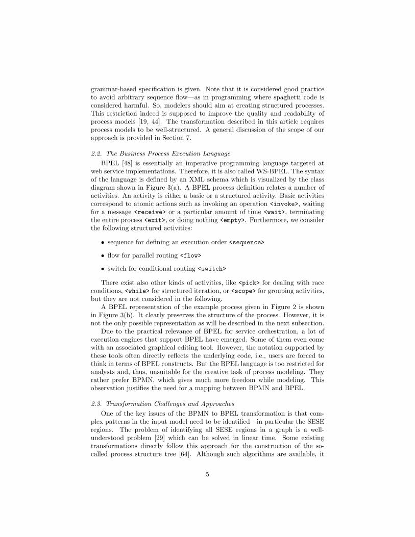
grammar-based specification is given. Note that it is considered good practiceto avoid arbitrary sequence flow—as in programming where spaghetti code isconsidered harmful. So, modelers should aim at creating structured processes.This restriction indeed is supposed to improve the quality and readability ofprocess models [19, 44]. The transformation described in this article requiresprocess models to be well-structured. A general discussion of the scope of ourapproach is provided in Section 7.
2.2. The Business Process Execution LanguageBPEL [48] is essentially an imperative programming language targeted at
web service implementations. Therefore, it is also called WS-BPEL. The syntaxof the language is defined by an XML schema which is visualized by the classdiagram shown in Figure 3(a). A BPEL process definition relates a number ofactivities. An activity is either a basic or a structured activity. Basic activitiescorrespond to atomic actions such as invoking an operation <invoke>, waitingfor a message <receive> or a particular amount of time <wait>, terminatingthe entire process <exit>, or doing nothing <empty>. Furthermore, we considerthe following structured activities:
• sequence for defining an execution order <sequence>
• flow for parallel routing <flow>
• switch for conditional routing <switch>
There exist also other kinds of activities, like <pick> for dealing with raceconditions, <while> for structured iteration, or <scope> for grouping activities,but they are not considered in the following.
A BPEL representation of the example process given in Figure 2 is shownin Figure 3(b). It clearly preserves the structure of the process. However, it isnot the only possible representation as will be described in the next subsection.
Due to the practical relevance of BPEL for service orchestration, a lot ofexecution engines that support BPEL have emerged. Some of them even comewith an associated graphical editing tool. However, the notation supported bythese tools often directly reflects the underlying code, i.e., users are forced tothink in terms of BPEL constructs. But the BPEL language is too restricted foranalysts and, thus, unsuitable for the creative task of process modeling. Theyrather prefer BPMN, which gives much more freedom while modeling. Thisobservation justifies the need for a mapping between BPMN and BPEL.
2.3. Transformation Challenges and ApproachesOne of the key issues of the BPMN to BPEL transformation is that com-
plex patterns in the input model need to be identified—in particular the SESEregions. The problem of identifying all SESE regions in a graph is a well-understood problem [29] which can be solved in linear time. Some existingtransformations directly follow this approach for the construction of the so-called process structure tree [64]. Although such algorithms are available, it
5

<process>
<flow>
<sequence>
<invoke name="act1"/>
<invoke name="act2"/>
<receive name="ev1"/>
</sequence>
<sequence>
<invoke name="act3"/>
<switch>
<case cond="cond1">
<sequence>
<invoke name="act4"/>
<wait name="ev2"/>
</sequence>
</case>
<case cond="cond2">
<invoke name="act5"/>
</case>
</switch>
</sequence>
</flow>
</process>
Figure 3: (a) BPEL syntax (left) and (b) example process corresponding to Figure 2 (right)
is worthwhile to see how this transformation can be solved with model trans-formation approaches in order to raise the level of abstraction and to improvereadability. Note that, from an algorithmic point of view, the reverse transfor-mation from BPEL to BPMN is the easier one, because in BPEL the structureis explicitly given by the tree structure of XML; it can be simply traversed.
Besides the identification of SESE regions, there is also a different way toderive BPEL from BPMN. BPEL provides a non-structured construct, so-calledcontrol links, that allows the definition of directed dependency graphs. A controllink between activities A and B indicates that B cannot start before A has beencompleted. Also a condition can be attached that has to be true in order toexecute B. There are some restrictions on the use of control links, e.g., theymust not create cyclic control dependencies and must not cross the boundaryof a while activity. Still a straightforward transformation from BPMN intoBPEL can be implemented by excessively using control links and so-called eventhandlers [50]. However, this decreases readability since the structure of theprocess does not become as apparent as, e.g., in Figure 3(b).
A wide range of process models can be translated into BPEL respectingtheir structure as far as possible. For instance, an efficient transformation forquasi-structured processes, i.e., processes that can be re-written into perfectlystructured ones [51], has been proposed that is based on SPQR tree decomposi-tion [15]. However, this result is specific to the language and based on a manualprogramming effort.
6

In the GraBaTs 2009 synthesis case definition [12], four criteria for the eval-uation of transformations have been proposed which can be used to evaluatethe transformation approach presented in this article:
• Completeness: Which classes of processes can be transformed?
• Correctness: The transformation should preserve the execution semanticsof the BPMN process model. This question is beyond the scope of thisarticle which is mainly about syntax analysis. However, we will discussthe correctness of the proposed parser.
• Readability: The BPEL process definitions produced by the transforma-tion as well as the transformation itself should be readable (although thelatter is not explicitly stated in [12]). Readable BPEL basically means thatblock-structured control-flow constructs such as <sequence>, <while>,<switch>, etc. should be preferred over control links.
• Reversibility: The transformation should be accompanied by a reversetransformation; ideally a mechanism for bidirectional model synchroniza-tion should be provided.
3. Hypergraph Models
In this section we first introduce hypergraphs as a uniform diagram represen-tation model [46]. We continue with the introduction of hypergraph grammarsas a device for language definition. Finally, a common way for computing se-mantic representations of diagrams is described, namely attribute hypergraphgrammars. That way, the introduction of the parser with semantic computationsin Section 6 is prepared.
3.1. Hypergraphs as a Uniform Diagram Representation ModelRoughly speaking, hypergraphs are graphs where edges are allowed to con-
nect (also called visit) an arbitrary number of nodes depending on the edges’slabels (see [11] for formal definitions). In this case, the edges are called hyper-edges. Vice versa, normal graphs are specific hypergraphs where all edges visitexactly two (not necessarily distinct) nodes, i.e., a source and a target node.For the sake of brevity, hypergraphs and hyperedges are occasionally just calledgraphs and edges in the following.
Figure 4 shows an example of a hypergraph, which actually correspondsto the process of Figure 2.3 Hyperedges are graphically represented by boxes.Nodes are represented as black dots sometimes identified by numbers. The nodesvisited by an edge are connected to this edge by lines called tentacles. Tentaclesare numbered to indicate the roles of the connected nodes. For instance, BPMN
3Note that properties such as the labels of activities or the conditions of gateways are notgraphically represented but can be attached as properties to the hyperedges.
7

act act inter2 2 2
2 2
1 1 12 6 10 16
start pgw act inter pgw end1 1 12232
4
1 32
1 32
1 32
4
1 2
1 11
47 11 13 15
18
act xgw xgw
act
1 3
4
1 3
4
21
1 23 5
8
9 12
14
17
Figure 4: Hypergraph model of Figure 2
activities (edge label act) always have an incoming (1) and an outgoing tentacle(2); parallel and exclusive gateways (edge label pgw/xgw) always have fourtentacles: left (1), top (2), right (3), and bottom (4).4 Note that BPMN arrowsfor sequence flow are represented only implicitly in the hypergraph model shownin Figure 4. Thus, if two activities are connected by an arrow, the outgoing nodeof the first activity’s edge coincides with the incoming node of the latter.
Hypergraphs are well-suited as a diagram model, because they can easilyhandle the requirement that diagram components typically have several distinctattachment areas at which they can interact with other diagram components.Thus, hypergraphs allow for a homogeneous representation of diagram compo-nents and their relations via hyperedges. Whereas the actual components canbe modeled by hyperedges, attachment areas can be modeled by nodes visitedby the hyperedge. This observation actually has led to the implementationof the diagram editor generator DiaGen [47], which is based on hypergraphs,hypergraph transformations, and hypergraph grammars.
Note that the transformation of a concrete business process diagram into itshypergraph representation is beyond the scope of this article. This actually isan easy task compared to the transformation of BPMN into BPEL, where theoverall structure of the process needs to be identified. For instance, this stepcould be performed with a model transformation tool as an exogenous trans-formation. Layout information thereby can be completely discarded. However,then the reverse transformation would have to include a layout step for theconcrete arrangement of the components. A DiaGen solution to the BPMN-to-BPEL case that includes an editor for business process diagrams has alsobeen developed [43]. However, this solution uses another technique that will bebriefly described in Section 3.3.
4Note that only three of those are used at a time, but with four tentacles the correspondenceto the corners of the concrete diamond-shaped diagram component becomes more obvious.
8

4
Process ::= start Flow end
Flow FlowFlElem::=n1 n2 n1 n2
FlElemn1 n2
FlElemn1 n2
actn1 n2
::= intern1 n2
pgwn1
pgwn2
Flow
Flow
xgwn1
xgwn2
Flow
Flow
1 121
1 2 1 2 1 2 1 2
1 2 1 2 1 2
1 2
1 2
1 32
4
1 32
4
1 2
1 2
1 32
4
1 32
4
P1
P2|3
P4|5...
…|6|7
xgwn1
xgwn2
Flow2 1
1 32
4
1 32
Figure 5: Productions of GProcess
3.2. Hypergraph Grammars for Language DefinitionAs already mentioned, the hypergraph language of well-structured process
models can be defined using a Hyperedge Replacement Grammar (HRG) [11].Each HRG consists of two finite sets of terminal and nonterminal hyperedgelabels and a starting hypergraph, which contains only a single hyperedge with anonterminal label. The syntax is specified by a set of hypergraph productions.Figure 5 shows the productions of the HRG GProcess. For the sake of conciseness,loops are not considered. Productions L ::= R1, . . . , L ::= Rk with the sameleft-hand side L are drawn as L ::= R1| . . . |Rk. The types start, end, inter, act,pgw and xgw are the terminal hyperedge labels. The set of nonterminal labelsconsists of Process, Flow and FlElem. The starting hypergraph consists of justa single Process edge.
The application of a context-free production removes an occurrence e of theleft-hand side hyperedge from the host graph and replaces it by the hypergraphof the right-hand side, see [11]. Matching node labels of left- and right-handsides determine how the right-hand side has to fit in after removing e. Anexample derivation is shown in Figure 6 (tentacle numbers are omitted in thisfigure). The hypergraph language generated by a grammar is defined by the setof all hypergraphs that can be derived from the starting hypergraph and thathave only terminal edges. For GProcess this is just the set of structured BPMNhypergraphs we want to cover.
As in the string setting, hypergraphs can be syntactically analyzed by aparser with respect to a given grammar. To this end, derivation trees are con-structed (if existing). Such a hypergraph parser is part of the DiaGen system[47]. It uses dynamic programming techniques for the construction of derivationtrees (similar to the string parser developed by Cocke, Younger, and Kasami[31]). The details of this parser are described in [5].
9

Process start Flow end
pgw pgw
Flow
Flow
P1
P2
start FlElem end
P6
start end
2*(P2,P4)
pgw pgw
act
act
start end
Figure 6: An example derivation
pgwn1
pgwn2
Flow1
Flow2
1 2
1 2
1 32
4
1 32
4
FlElem.bpel:= "<flow>" +
Flow1.bpel +
Flow2.bpel +
"</flow>"
FlElemn1 n2
::=1 2
Figure 7: Example production with attribute evaluation rule
3.3. Attribute Hypergraph Grammars for Semantic ComputationsThe DiaGen system also supports the translation of a diagram into some
domain-specific data structure. For this purpose, it provides attribute eval-uation [45], a well-known technique in the domain of compiler construction[32]. Basically, each hyperedge carries some attributes. Number and types ofthese attributes depend on the hyperedge label. Productions of the hypergraphgrammar may be augmented by attribute evaluation rules which assign valuesto attributes of the corresponding edges. An attribute hypergraph grammar forthe synthesis of BPEL from BPMN has been proposed in [43] as an alternativesolution to the case. An example production with an attribute evaluation ruleis shown in Figure 7. The subscript numbers do not belong to the edge labelbut are used to refer to the different occurrences of edges with the same label.
After parsing, attribute evaluation works as follows. Each hyperedge thatoccurs in the derivation tree has a distinct number of attributes. Grammarproductions that have been used for creating the tree impose instantiated at-tribute evaluation rules. Those determine how attribute values are computedas soon as the values of others are known. The attribute evaluation mechanismthen computes a valid evaluation order. Some or even all attribute values ofterminal edges are already known; they have been derived from attributes ofthe diagram components. For instance, hyperedges with label act have a nameattribute representing the name of the respective activity.
Attribute string grammars can be translated into parsers in a straightfor-ward way, e.g., by using a parser generator or a combinator framework. Thisalso applies to the graph parser combinators that will be introduced in Sec-tion 5. A disadvantage of attribute grammars is, however, that usually thereverse transformation cannot be derived automatically (pair grammars havebeen suggested to this end [53]).
10

4. Functional Logic Programming and Parser Combinators
Since our framework of graph parser combinators is implemented in the pro-gramming language Curry [22], we introduce the relevant concepts of Curry inthis section. Moreover, we discuss the ideas behind (string) parser combinatorsand recapitulate why functional logic languages are a natural platform for those.
4.1. The Programming Language CurryCurry is a declarative multi-paradigm language combining features from
both functional and logic programming (see [3, 24] for recent surveys). Thesyntax of Curry is close to Haskell [52]. The main addition are free (logic)variables in conditions and right-hand sides of defining rules. In functional pro-gramming, one is interested in the computed value, whereas logic programmingemphasizes the different bindings (answers). Consequently, Curry computes foreach input expression its value together with a substitution for the free variablesoccurring in the input expression.
A Curry program consists of the definition of data types and operations onthese types. Although we often use the term “function” as a synonym of “definedoperation” as in functional programming, it should be noted that operations inCurry might yield more than one result on the same input due to the logicprogramming features. Thus, Curry operations are not functions in the classi-cal mathematical sense so that some authors use the term “non-deterministicfunctions” [17]. Nevertheless, Curry programs have a purely declarative seman-tics where non-deterministic operations are modeled as set-valued functions (tobe more precise, down-closed partially ordered sets are used as target domainsin order to cover non-strictness, see [17] for a detailed account of this model-theoretic semantics).
In a Curry program, operations are defined by conditional equations withconstraints in the conditions. They are evaluated lazily and can be called withpartially instantiated arguments. This feature will be heavily used later on.Calls with free variables are evaluated by a possibly non-deterministic instan-tiation of the required arguments, i.e., arguments whose values are demandedto decide the applicability of a rule. This mechanism is called narrowing [58].Curry is based on a refinement of narrowing, called “needed narrowing” [1],which is optimal for particular classes of programs, i.e., shortest derivations anda minimal number of solutions are computed (see [1] for more details).
As an example, consider the Curry program given in Figure 8. It defines apolymorphic data type for lists, and operations to compute the concatenationof lists and the last element of a list. Note, however, that lists are a built-indata type with a more convenient syntax, e.g., one can write [x,y,z] insteadof x:y:z:[] and [a] instead of the list type “List a”.
Logic programming is supported by admitting function calls with free vari-ables, see (ys++[z]) in Figure 8, and constraints in the condition of a definingrule. In contrast to Prolog, free variables need to be declared explicitly to maketheir scopes clear; in the example this is expressed by “where ys,z free”.
11

data List a = [] | a : List a --[a] denotes "List a"
--"++" is a right-associative infix operator(++) :: [a] → [a] → [a][] ++ ys = ys(x:xs) ++ ys = x : (xs ++ ys)
last :: [a] → alast xs | (ys ++ [z]) =:= xs
= z where ys,z free
Figure 8: A Curry program with operations on lists
Conditional program rules have the form “l | c = r” specifying that l is re-ducible to r if c is satisfied. The condition c is a constraint, i.e., an expressionof the built-in type Success. For instance, the trivial constraint success is anexpression of type Success that denotes the always satisfiable constraint. Anequational constraint e1 =:= e2 is satisfiable if both sides e1 and e2 are reducibleto unifiable constructor terms. Furthermore, if c1 and c2 are constraints, c1 &c2 denotes their concurrent conjunction, i.e., this expression is evaluated byproving both argument constraints concurrently. For instance, the rule defininglast in Figure 8 states in its condition that z is the last element of a given listxs if there exists a list ys such that the concatenation of ys and the one-elementlist [z] is equal to the given list xs.
Note that, in contrast to Haskell, the evaluation of “last []” does not raisea run-time error but fails. Similar to logic programming, failure is not a run-time error in Curry but a useful programming technique: if some evaluation,i.e., a rule application, leads to a failure, a different rule is chosen. Thus, allapplicable rules are tried to evaluate some function call (in contrast to Haskell[52] which commits to the first applicable rule). This kind of non-determinismcan be implemented by backtracking or by a parallel search for all solutions.The concrete implementation is specific to each Curry system.
The execution model of Curry is based on narrowing, a combination of vari-able instantiation and reduction. For instance, the expression (ys++[1]) isevaluated to several results: the list [1] by instantiating ys to [] using the firstequation, to the partially unknown list [x,1] by instantiating ys to [x] usingthe second equation and then the first equation, and so on to terms of the form[x,y,1], [x,y,z,1], . . . To restrict these potentially infinite number of non-deterministic computations, one usually puts such expressions in the context ofconstraints. For instance, the equational constraint (ys++[x])=:=[1,2] causesa finite computation space containing the unique solution where ys and x arebound to [1] and 2, respectively. This technique is exploited in Figure 8 todefine the operation last conveniently.
As already remarked, operations in Curry may yield more than one resultfor some input due to the logic programming features. For instance, consider
12

the operation removeSome defined as follows:
removeSome :: a → [a] → [a]removeSome x xs | xs=:=(xs1++x:xs2) = xs1++xs2
where xs1,xs2 free
The condition states that the input list xs is decomposable into xs1, x, andxs2, and the result is the concatenation of xs1 and xs2. Thus, removeSomereturns any list which can be obtained by removing some occurrence of theinput element x from the input list xs. Actually, non-deterministic operationslike removeSome are a useful programming technique which will be used toimplement (graph) parsers in a convenient manner.
The combination of functional and logic programming features has led tonew design patterns [2] and better abstractions for application programming,e.g., as shown for programming with databases [7, 13], GUI programming [20],web programming [21, 23, 26], or string parsing ([10] and Section 4.2). Inthis article, we show how to exploit these combined features to construct abidirectional transformation between a visual graph-oriented language and aterm-oriented language.
As already mentioned, this article is a literate Curry program [33], i.e., thearticle’s source text is directly executable. In a literate Curry program, all realprogram code starts with the special character “>”. This is called Bird-style codeand comments. Curry code not starting with “>”, e.g., the code in Figure 8, isjust for reader’s information and not required to run the program, i.e., it is acomment. Occasionally, we will also use Curry line comments, which start with“--”. As an example of code that counts, consider the following declaration ofa main operation which applies the parser processS (to be defined in Section 6)to the example hypergraph ex shown in Figure 4 and pretty-prints the resultingBPEL representation in XML:
> main = let bpel = getSemRep (findfirst (\s → s=:=processS ex))> in putStrLn (bpel2xml bpel) --output result
Since operations in Curry might yield more than one result, we select one valueof “processS ex” using findfirst and print its XML representation (the oper-ations used here will be defined later). Thus, executing this program will resultin the output shown in Figure 3(b).
There exist various implementations of Curry,5 where three major systemsare available for general use and, thus, can run our transformation:
• MCC (Munster Curry Compiler) [35] generates fast native code.
• PAKCS (Portland Aachen Kiel Curry System) [25] compiles Curry to Pro-log as an intermediate language.
• KiCS (Kiel Curry System) [8] compiles Curry to Haskell.
5http://www.curry-language.org/implementations/overview (accessed on 2010-07-30)
13
4.2. A Brief Introduction to Parser CombinatorsIn functional programming, the most popular approach to parsing is based
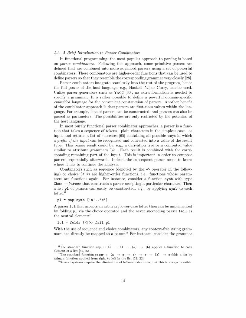
on parser combinators. Following this approach, some primitive parsers aredefined that are combined into more advanced parsers using a set of powerfulcombinators. These combinators are higher-order functions that can be used todefine parsers so that they resemble the corresponding grammar very closely [28].
Parser combinators integrate seamlessly into the rest of the program, hencethe full power of the host language, e.g., Haskell [52] or Curry, can be used.Unlike parser generators such as Yacc [30], no extra formalism is needed tospecify a grammar. It is rather possible to define a powerful domain-specificembedded language for the convenient construction of parsers. Another benefitof the combinator approach is that parsers are first-class values within the lan-guage. For example, lists of parsers can be constructed, and parsers can also bepassed as parameters. The possibilities are only restricted by the potential ofthe host language.
In most purely functional parser combinator approaches, a parser is a func-tion that takes a sequence of tokens—plain characters in the simplest case—asinput and returns a list of successes [65] containing all possible ways in whicha prefix of the input can be recognized and converted into a value of the resulttype. This parser result could be, e.g., a derivation tree or a computed valuesimilar to attribute grammars [32]. Each result is combined with the corre-sponding remaining part of the input. This is important in order to composeparsers sequentially afterwards. Indeed, the subsequent parser needs to knowwhere it has to continue the analysis.
Combinators such as sequence (denoted by the *> operator in the follow-ing) or choice (<|>) are higher-order functions, i.e., functions whose param-eters are functions again. For instance, consider a function symb with typeChar → Parser that constructs a parser accepting a particular character. Thena list pl of parsers can easily be constructed, e.g., by applying symb to eachletter:6
pl = map symb [’a’..’z’]
A parser lcl that accepts an arbitrary lower-case letter then can be implementedby folding pl via the choice operator and the never succeeding parser fail asthe neutral element:7
lcl = foldr (<|>) fail pl
With the use of sequence and choice combinators, any context-free string gram-mars can directly be mapped to a parser.8 For instance, consider the grammar
6The standard function map :: (a → b) → [a] → [b] applies a function to eachelement of a list [52, 22].
7The standard function foldr :: (a → b → b) → b → [a] → b folds a list byusing a function applied from right to left in the list [52, 22].
8Several systems require the elimination of left-recursive rules, but this is always possible.
14

B ::= ‘(’ B ‘)’ B
| ε
of well-formed bracket terms derivable from the only nonterminal and, thus,starting symbol B. Given an always succeeding primitive parser epsilon thatdoes not consume any input, a parser for this language can be constructed asfollows:
b = symb ’(’ *> b *> symb ’)’ *> b<|> epsilon
A lot of research has been put into developing more and more sophisticatedstring parser combinator libraries, e.g., [34, 61, 66]. Those rely on differentapproaches to search, backtracking control, parser composition, and result con-struction.
Functional logic parser combinators, proposed for the first time in [10], haveall the advantages of purely functional ones but additionally benefit from thefollowing merits of logic-based parsers:
• Non-determinism is the default behavior, i.e., it is not necessary to imple-ment search based on backtracking or the “lists of successes” technique[65] by hand.
• Parsers can be used for language generation thanks to the fact that aparser is not a function but rather a relation.
• Incomplete information can be handled conveniently by using free (logic)variables.
The possibilities of dealing with incomplete information are particularly in-teresting. For instance, free variables can be used as placeholders in the inputsentence. While parsing, these variables are instantiated with the tokens thatcan occur at this particular position in order to get a valid sentence of the lan-guage. In the string setting, this is a nice feature coming for free but not beinguseful directly. For instance, to exploit this for error correction, the positionand number of the missing token needs to be known or all possible positionswould have to be tried. This is not really feasible. However, in the graph set-ting, where we deal with sets, this effect is much more powerful as we will see.Actually, this is already the key idea for deriving meaningful graph completions.
Note that purely logic languages would not be equally well-suited for ourpurpose, because those do not support the straightforward definition of higher-order functions such as combinators. Thus, the “remaining input” would haveto be passed more explicitly resulting in a lot of boilerplate code, i.e., code thathas to be included in many places of the program with little or no alteration.Prolog provides Definite Clause Grammars (DCGs), a syntactic sugar to hidethe difference list mechanism needed to build reasonably efficient string parsers
15

in logic languages. However, a graph is not linearly structured. Hence, this no-tation cannot be used for graph parsing. Tanaka’s definite clause set grammars[63], a DCG-like formalism for free-word-order languages, are not supported bycommon Prolog systems.
Having this in mind, graph parsing appears to be a domain asking for multi-paradigm declarative programming languages [24] such as Curry. In this domaintheir benefits really stand out. The inherent need for logic features in graphparsing will be further motivated in the following.
5. Graph Parser Combinators: The Grappa Framework
The graph parser combinator library Grappa allows the convenient andstraightforward construction of hypergraph parsers for HRGs. The implementa-tion of Grappa in Curry indeed exploits both functional and logic programmingtechniques. That way, the following features have been achieved:
• Straightforward translation of HRGs to reasonably efficient parsers.
• Application-specific results due to powerful semantic computations.
• Easy to use for people familiar with parser combinators.
• Usable context information. This allows the convenient description oflanguages that cannot be defined with an HRG.
• Robust against errors. Valid subgraphs can be extracted.
• Bidirectionality. Besides syntax analysis, parsers can be used to constructor complete graphs of the intended language or even to create a graph fromits semantic representation as required for the transformation of BPELinto BPMN.
In this section, we introduce all parts of the Grappa9 library that are requiredfor the implementation of the BPMN parser in Section 6.
5.1. Type Declarations for Graphs and Graph ParsersWe start by defining the basic data structures for representing graphs and
hypergraphs. For the sake of simplicity, nodes are represented by integer num-bers. A graph is declared as a list of edges each with its incident nodes. Atype for the edge labels t can be passed as a type parameter (in the simplestcase this can be just strings representing their labels as in the original Grappaversion [40]). The tentacle numbers correspond to the position of a node in thelist of incident nodes.
9http://www.unibw.de/inf2/grappa (accessed on 2010-07-30)
16

8
3131 11
73
start
act
pgw
act
pgw end
2
2
4
2
4
21
1
1
2
4
6
5
> ex_sm :: Graph String> ex_sm = [("start", [1]), ("pgw", [1,2,4,3]), ("act", [2,6]),> ("act", [3,7]), ("pgw", [5,6,8,7]), ("end", [8])]
Figure 9: A small example BPMN hypergraph and a representation as a Curry term
> type Node = Int> type Edge t = (t, [Node])> type Graph t = [Edge t]
Note that the actual order of edges in the list does not matter. Rather thelist of edges representing a graph is interpreted as a multiset. Consequently,there are a lot of terms describing the very same graph. This approach is theeasiest one to implement and understand, but it has also some weaknesses.Those will be discussed in Section 7. Furthermore, isolated nodes cannot bedirectly represented, because the nodes of a hypergraph are implicitly given asthe union of all nodes incident to its edges. But this restriction is not severesince isolated nodes simply do not occur in many hypergraph application areas.In the context of visual languages, diagram components are represented byhyperedges, and nodes just represent their attachment areas, i.e., each node isvisited by at least one edge (see Section 3).
Figure 9 shows a small example of a BPMN hypergraph and its correspond-ing graph representation in Curry where String-labeled edges are used. Notethat node numbers and tentacle numbers have to be clearly distinguished. Thetentacle numbers are only represented implicitly as the position of a node in anedge’s node list.
Next, the declaration of the type Grappa representing a graph parser isintroduced. This type is parameterized over the type res of semantic values as-sociated to graphs. Graph parsers are non-deterministic operations from graphsto pairs consisting of the parsing result and the graph that remains after suc-cessful parser application. Note that the non-remaining parts of the graph havebeen consumed in the course of parsing. In contrast to Haskell, it is not requiredto explicitly deal with parsing errors and backtracking. Instead, similar to [10],the non-determinism inherent to functional logic programming languages is ex-ploited, which yields the following, very concise type declaration:
> type Grappa t res = Graph t → (res, Graph t)
> getSemRep (r,_) = r --access semantic representation
17

5.2. Primitive Parsers and Basic CombinatorsNow we define some primitives for the construction of graph parsers. Given
an arbitrary value v, pSucceed always succeeds returning v as a result withoutany consumption of the input graph g:
> pSucceed :: res → Grappa t res> pSucceed v g = (v, g)
In contrast, eoi only succeeds if the graph is already completely consumed.In this case, the result () is returned, the only value of the so-called unit type.Note that it is not necessary to state explicitly that eoi fails on non-emptyinputs—the absence of a rule is sufficient.
> eoi :: Grappa t ()> eoi [] = ((), [])
An especially important constructor of primitive parsers is edge, the graphequivalent of symb, cf. Section 4.2. The parser “edge e” only succeeds if thegiven edge e is part of the given input graph g. In contrast to symb, it doesnot have to be at the beginning of the token list though. If g contains e, eis consumed, i.e., removed from g. The parser edge is implemented in a logicprogramming style making use of an equational constraint (note the similarityto the operation removeSome in Section 4.1).
> edge :: Edge t → Grappa t ()> edge e g | g=:=(g1++e:g2) = ((), g1++g2)> where g1, g2 free
If g, which is the list representation of the input graph, can be decomposedinto g1, e and g2, the edge e indeed is contained in g. In this case, e has to beconsumed. This is realized by returning just g1++g2 as the remaining graph.
Figure 10 defines some basic graph parser combinators. The choice operator<|> takes two parsers and succeeds if either the first or the second one succeedson the particular input graph g (note that the non-determinism provided byfunctional logic programming is quite handy here). Two parsers can also becombined via <*>, the successive application where the result is constructed byfunction application. Thereby, the first parser p has to return a function pvas result that eventually is applied to the result qv returned by the successiveparser q. Note that q is applied to g1, i.e., the input that p has left. The correct(intended) order of evaluation is enforced by using Curry’s case construct.
For convenience, we define the combinators *> and <* that throw awaythe result of either the left or the right parser. Indeed, the pure success ofa parser is often sufficient for the remaining computation. Then a particularresult is not at all required. For plain language recognition without semanticcomputations, only the combinator *> is needed, see the (textual) bracket termexample of Section 4.2. Note that the result types of the argument parsers inthe combinators *> and <* might differ but they have to process graphs withthe same edge type t. This is reasonable since they operate on the same graphbut can compute different kinds of semantic information.
18
> (<|>) :: Grappa t res → Grappa t res → Grappa t res> (p1 <|> p2) g = p1 g> (p1 <|> p2) g = p2 g
> (<*>) :: Grappa t (r1 → r2) → Grappa t r1 → Grappa t r2> (p <*> q) g = case p g of> (pv, g1) → case q g1 of> (qv, g2) → (pv qv, g2)
> (<$>) :: (res1 → res2) → Grappa t res1 → Grappa t res2> f <$> p = pSucceed f <*> p
> (<$) :: res1 → Grappa t res2 → Grappa t res1> f <$ p = const f <$> p
> (<*) :: Grappa t res1 → Grappa t res2 → Grappa t res1> p <* q = (\x _ → x) <$> p <*> q
> (*>) :: Grappa t res1 → Grappa t res2 → Grappa t res2> p *> q = (\_ x → x) <$> p <*> q
Figure 10: Basic graph parser combinators
The parser transformers <$> and <$ can be used to either apply a functionto the result of a parser or to just replace it by another value, respectively. Notethat some of the other combinators are defined in terms of <$>. For instance, <$can be defined using <$> by constructing a constant function from the respectivevalue.10 Another example application of <$> is given below in the definition ofthe chain combinator.
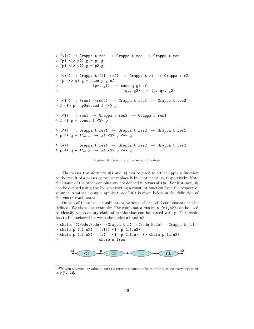
On top of these basic combinators, various other useful combinators can bedefined. We show one example: The combinator chain p (n1,n2) can be usedto identify a non-empty chain of graphs that can be parsed with p. This chainhas to be anchored between the nodes n1 and n2.
> chain::((Node,Node) → Grappa t a) → (Node,Node) → Grappa t [a]> chain p (n1,n2) = (:[]) <$> p (n1,n2)> chain p (n1,n2) = (:) <$> p (n1,n) <*> chain p (n,n2)> where n free
1 2n1 n2nG1 Gk…G2
10Given a particular value v, const v returns a constant function that maps every argumentto v [52, 22].
19
The definition of chain can be read as: “chain p (n1,n2)” succeeds if“p (n1,n2)” succeeds. Then a singleton list with its result is returned.11
It may also succeed by running “p (n1,n)” for some node n and thereafter“chain p (n,n2)” again. Then their results are combined via the list con-structor (:). Note that chain can be conveniently defined because the innernode n does not need to be known in advance. It can simply be defined as afree variable which will be instantiated according to the narrowing semantics ofCurry. Representing graph nodes as free variables actually is a functional logicdesign pattern [2] that we will use some more times in the remainder of thisarticle.
5.3. Translation of the BPMN Grammar to a ParserBefore the BPMN to BPEL transformation will be introduced in Section 6,
we show the implementation of a direct mapping from HRGs to Grappa parsers.We will see that parsers indeed resemble grammars very closely.
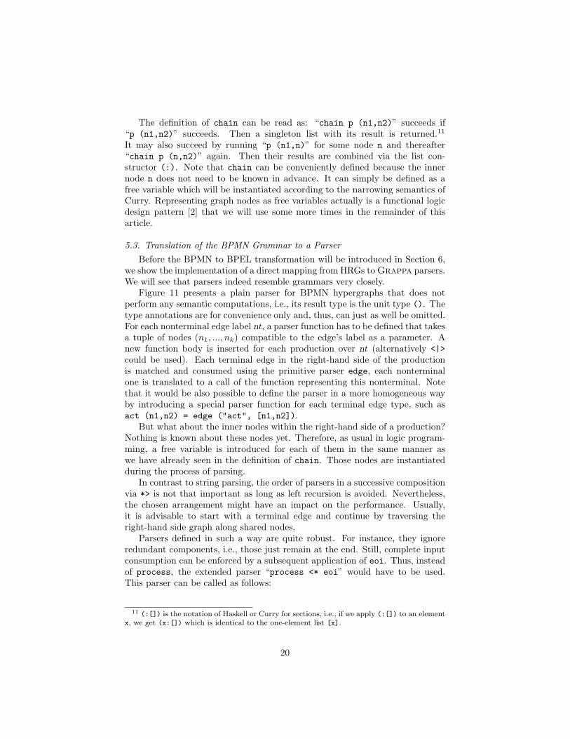
Figure 11 presents a plain parser for BPMN hypergraphs that does notperform any semantic computations, i.e., its result type is the unit type (). Thetype annotations are for convenience only and, thus, can just as well be omitted.For each nonterminal edge label nt, a parser function has to be defined that takesa tuple of nodes (n1, ..., nk) compatible to the edge’s label as a parameter. Anew function body is inserted for each production over nt (alternatively <|>could be used). Each terminal edge in the right-hand side of the productionis matched and consumed using the primitive parser edge, each nonterminalone is translated to a call of the function representing this nonterminal. Notethat it would be also possible to define the parser in a more homogeneous wayby introducing a special parser function for each terminal edge type, such asact (n1,n2) = edge ("act", [n1,n2]).
But what about the inner nodes within the right-hand side of a production?Nothing is known about these nodes yet. Therefore, as usual in logic program-ming, a free variable is introduced for each of them in the same manner aswe have already seen in the definition of chain. Those nodes are instantiatedduring the process of parsing.
In contrast to string parsing, the order of parsers in a successive compositionvia *> is not that important as long as left recursion is avoided. Nevertheless,the chosen arrangement might have an impact on the performance. Usually,it is advisable to start with a terminal edge and continue by traversing theright-hand side graph along shared nodes.
Parsers defined in such a way are quite robust. For instance, they ignoreredundant components, i.e., those just remain at the end. Still, complete inputconsumption can be enforced by a subsequent application of eoi. Thus, insteadof process, the extended parser “process <* eoi” would have to be used.This parser can be called as follows:
11 (:[]) is the notation of Haskell or Curry for sections, i.e., if we apply (:[]) to an elementx, we get (x:[]) which is identical to the one-element list [x].
20

4
Process ::= start Flow end
Flow FlowFlElem::=n1 n2 n1 n2
FlElemn1 n2
FlElemn1 n2
actn1 n2
::= intern1 n2
pgwn1
pgwn2
Flow
Flow
xgwn1
xgwn2
Flow
Flow
1 121
1 2 1 2 1 2 1 2
1 2 1 2 1 2
1 2
1 2
1 32
4
1 32
4
1 2
1 2
1 32
4
1 32
4
P1
P2|3
P4|5...
…|6|7
xgwn1
xgwn2
Flow2 1
1 32
4
1 32
> process :: Grappa String ()> process = edge ("start", [n1]) *>> flow (n1,n2) *>> edge ("end", [n2])> where n1,n2 free
> flow :: (Node,Node) → Grappa String ()> flow (n1,n2) = flElem (n1,n2)> flow (n1,n2) = flElem (n1,n) *>> flow (n,n2)> where n free
> flElem :: (Node,Node) → Grappa String ()> flElem (n1,n2) = edge ("act", [n1,n2])> flElem (n1,n2) = edge ("inter", [n1,n2])> flElem (n1,n2) = edge ("pgw", [n1,n1t,n1r,n1b]) *>> flow (n1t,n2t) *>> edge ("pgw", [n2l,n2t,n2,n2b]) *>> flow (n1b,n2b)> where n1t,n1r,n1b,n2l,n2t,n2b free> flElem (n1,n2) = edge ("xgw", [n1,n1t,n1r,n1b]) *>> flow (n1t,n2t) *>> edge ("xgw", [n2l,n2t,n2,n2b]) *>> flow (n1b,n2b)> where n1t,n1r,n1b,n2l,n2t,n2b free
Figure 11: Production of GProcess (cf. Figure 5) and the corresponding parser implementation
21

BPMN2BPEL> (process <* eoi) ex_sm((),[])More solutions? [Y(es)/n(o)/a(ll)] yNo more solutions
So, for the example input graph ex_sm shown in Figure 9, the pair ((),[])is returned. The list part [] represents the remaining graph, which is emptyhere (actually, we have enforced this with eoi). As a result the value () ofunit type () is returned. We can conclude from this evaluation that the graphex_sm is syntactically correct. Since we have searched for further solutions bypressing “y”, but did not found any, we can also conclude that there is only asingle derivation tree for ex_sm (the grammar GProcess actually is unambiguous).However, we cannot tell anything about the structure and meaning of ex_sm.This gap will be closed in the following section.
6. Constructing the BPMN to BPEL Transformation
Our parser constructed so far can only check whether the given graph is,or at least contains, a valid BPMN hypergraph. However, a major benefit ofthe combinator approach is that language-specific results can be computed in aflexible way. In this section we show how one can synthesize BPEL from BPMNby adding this transformation as a semantic computation to the BPMN parsingprocess. In the subsequent section, we discuss how this implementation can beexploited for various tasks beyond the transformation of BPMN into BPEL.
6.1. Typed BPMN HypergraphsIn order to transform BPMN into BPEL, edges of the BPMN hypergraphs
have to carry attributes, e.g., semantic information describing the label of anactivity or the kind of an intermediate event. For this purpose, we introducethe type of BPMN edges by the declaration of the data type BPMNComp:
> data BPMNComp => BPMNStart | BPMNEnd | BPMNPGW |> BPMNXGW String String | --conditions as params> BPMNActivity String | --label as param> BPMNInter BPMNInterKind String --kind and label as params>> data BPMNInterKind = BPMNWait | BPMNReceive
In contrast to the original work on functional logic graph parser combina-tors [40], we have extended the Grappa framework to typed hypergraphs. Thisextension is important for the comprehensive and correct generation of the cor-responding BPEL code. For instance, we can represent the example BPMNdiagram of Figure 2 as a graph over the edge type BPMNComp by the constant exgiven in Figure 12.
Actually, there are some degrees of freedom in modeling BPMN. For in-stance, we could have also represented the kind of gateway, i.e., exclusive orparallel, via an attribute (in the same way as we distinguished events).
22

> ex :: Graph BPMNComp
> ex = [(BPMNStart,[1]),(BPMNPGW,[1,2,4,3]),(BPMNActivity "act1",[2,6]),
> (BPMNActivity "act2",[6,10]),(BPMNPGW,[15,16,18,17]),
> (BPMNActivity "act3",[3,5]),(BPMNXGW "cond1" "cond2",[5,7,9,8]),
> (BPMNActivity "act4",[7,11]),(BPMNActivity "act5",[8,14]),
> (BPMNInter BPMNWait "ev2",[11,13]),(BPMNXGW "" "",[12,13,17,14]),
> (BPMNInter BPMNReceive "ev1",[10,16]),(BPMNEnd,[18])]
Figure 12: Representation of the example process in Figure 2 as a Curry term
6.2. Representing BPEL by Constructor TermsTo implement the parser that transforms BPMN into BPEL, we have to
define a representation of BPEL in Curry. The significant subset of BPELintroduced in Section 2.2 can be modeled as follows:
> type BPEL = [BPELComp]
> data BPELComp = Invoke String | Wait String | Receive String |> Flow BPEL BPEL | Switch String String BPEL BPEL
Thus, an element of type BPELComp describes some activity of a BPEL pro-cess, and elements of type BPEL (occurring as arguments of structured activ-ities) are simply sequences of BPEL activities. Since these sequences can bearbitrarily nested in structured activities, the target structure of our transfor-mation is basically a tree (in contrast to the graph-based source structure oftype Graph BPMNComp). Note that terms of the tree type BPEL12 can be trans-formed into BPEL-XML in a straightforward way as shown in Appendix A. Onecould also directly construct XML while parsing. However, the language Curryallows for more flexibility when dealing with constructor terms as above. Thiswill be important for supporting the reverse transformation.
6.3. Adding Semantics to the BPMN ParserFigure 13 shows the main part of our implementation, i.e., the extended
parser for BPMN where semantic computations have been added. As can be seenby the type of the main parsing operation processS, this parser works on typedhypergraphs with edges of type BPMNComp and returns a semantic value of typeBPEL (the BPEL tree corresponding to the input BPMN graph). To distinguishthis parser from the plain parser without semantic computations (result type()) presented in Figure 11, each function name is suffixed with the capitalletter S. Note that both parsers accept exactly the same graph language (apartfrom the different attributes associated to edges), i.e., the language generatedby the grammar given in Figure 5. This time, however, we use several staroperators (<*>, *>, and <*) to conveniently compose the semantical results.Recall that *> disregards the result of the left parser, <* disregards the result
12We use different fonts to distinguish the Curry type BPEL from the BPEL language.
23

> processS :: Grappa BPMNComp BPEL> processS = edge (BPMNStart,[n1]) *>> flowS (n1,n2) <*> edge (BPMNEnd,[n2])> where n1,n2 free
> flowS :: (Node,Node) → Grappa BPMNComp BPEL> flowS (n1,n2) = (:[]) <$> flElemS (n1,n2)> flowS (n1,n2) = (:) <$> flElemS (n1,n) <*> flowS (n,n2)> where n free
> flElemS :: (Node,Node) → Grappa BPMNComp BPELComp> flElemS (n1,n2) = translateInter itype name <$> edge (BPMNInter itype name, [n1,n2])> where itype,name free> translateInter BPMNWait = Wait> translateInter BPMNReceive = Receive> flElemS (n1,n2) = Invoke lab <$> edge (BPMNActivity lab, [n1,n2])> where lab free> flElemS (n1,n2) = edge (BPMNPGW, [n1,n1t,n1r,n1b]) *>> (Flow <$>> flowS (n1t,n2t) <*>> flowS (n1b,n2b)) <*> edge (BPMNPGW, [n2l,n2t,n2,n2b])> where n1t,n1r,n1b,n2l,n2t,n2b free> flElemS (n1,n2) = edge (BPMNXGW c1 c2, [n1,n1t,n1r,n1b]) *>> (Switch c1 c2 <$>> flowS (n1t,n2t) <*>> flowS (n1b,n2b)) <*> edge (BPMNXGW d1 d2, [n2l,n2t,n2,n2b])> where c1,c2,d1,d2,n1t,n1r,n1b,n2l,n2t,n2b free
Figure 13: BPMN parser that computes BPEL as a result
24
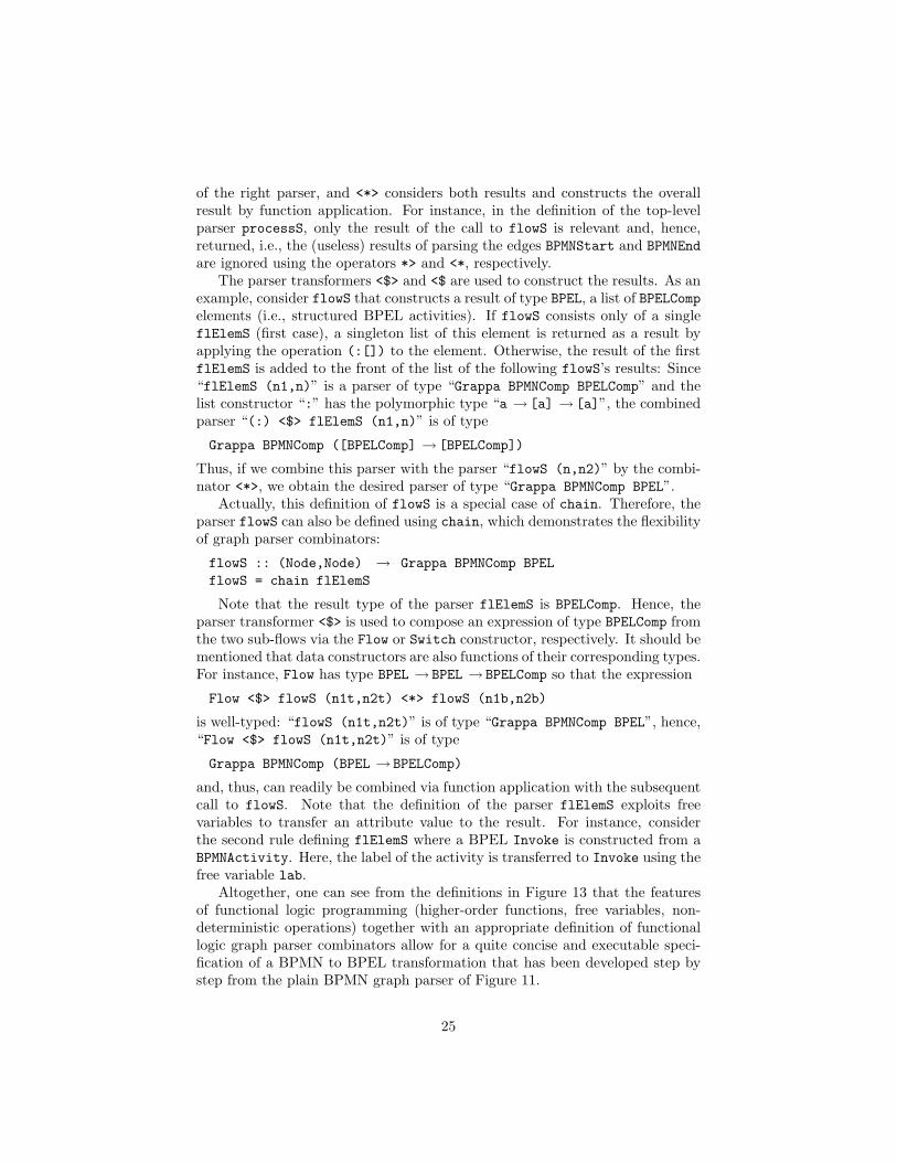
of the right parser, and <*> considers both results and constructs the overallresult by function application. For instance, in the definition of the top-levelparser processS, only the result of the call to flowS is relevant and, hence,returned, i.e., the (useless) results of parsing the edges BPMNStart and BPMNEndare ignored using the operators *> and <*, respectively.
The parser transformers <$> and <$ are used to construct the results. As anexample, consider flowS that constructs a result of type BPEL, a list of BPELCompelements (i.e., structured BPEL activities). If flowS consists only of a singleflElemS (first case), a singleton list of this element is returned as a result byapplying the operation (:[]) to the element. Otherwise, the result of the firstflElemS is added to the front of the list of the following flowS’s results: Since“flElemS (n1,n)” is a parser of type “Grappa BPMNComp BPELComp” and thelist constructor “:” has the polymorphic type “a → [a] → [a]”, the combinedparser “(:) <$> flElemS (n1,n)” is of type
Grappa BPMNComp ([BPELComp] → [BPELComp])
Thus, if we combine this parser with the parser “flowS (n,n2)” by the combi-nator <*>, we obtain the desired parser of type “Grappa BPMNComp BPEL”.
Actually, this definition of flowS is a special case of chain. Therefore, theparser flowS can also be defined using chain, which demonstrates the flexibilityof graph parser combinators:
flowS :: (Node,Node) → Grappa BPMNComp BPELflowS = chain flElemS
Note that the result type of the parser flElemS is BPELComp. Hence, theparser transformer <$> is used to compose an expression of type BPELComp fromthe two sub-flows via the Flow or Switch constructor, respectively. It should bementioned that data constructors are also functions of their corresponding types.For instance, Flow has type BPEL → BPEL → BPELComp so that the expression
Flow <$> flowS (n1t,n2t) <*> flowS (n1b,n2b)
is well-typed: “flowS (n1t,n2t)” is of type “Grappa BPMNComp BPEL”, hence,“Flow <$> flowS (n1t,n2t)” is of type
Grappa BPMNComp (BPEL → BPELComp)
and, thus, can readily be combined via function application with the subsequentcall to flowS. Note that the definition of the parser flElemS exploits freevariables to transfer an attribute value to the result. For instance, considerthe second rule defining flElemS where a BPEL Invoke is constructed from aBPMNActivity. Here, the label of the activity is transferred to Invoke using thefree variable lab.
Altogether, one can see from the definitions in Figure 13 that the featuresof functional logic programming (higher-order functions, free variables, non-deterministic operations) together with an appropriate definition of functionallogic graph parser combinators allow for a quite concise and executable speci-fication of a BPMN to BPEL transformation that has been developed step bystep from the plain BPMN graph parser of Figure 11.
25

Since the parser processS is not just a specification but also an executableCurry program, we can apply it to the example process of Figure 2 as follows:
BPMN2BPEL> processS ex([Flow [Invoke "act1",Invoke "act2",Receive "ev1"]
[Invoke "act3",Switch "cond1" "cond2" [Invoke "act4",Wait "ev2"]
[Invoke "act5"]]], [])More solutions? [Y(es)/n(o)/a(ll)] yNo more solutions
The result is a pair consisting of the semantic BPEL representation of thisgraph (which has been slightly reformatted to improve its readability) and theremaining graph, which is empty in this case. One can also print the result inXML format, as shown in the definition of the operation main (cf. Section 4).The function bpel2xml defined in Appendix A actually performs this transla-tion. The indentation performed by bpel2xml reflects the tree-structured resultof our parser. So, readable and structure-oriented BPEL is generated (cf. Fig-ure 3(b)) and the graph-oriented BPEL features do not need to be used.13
7. Discussion and Application
In this section we discuss the applicability of the transformation developedin Section 6. We will describe how the parser shown in Figure 13 can be usedfor graph completion and how the reverse transformation can be invoked. Wealso provide results of benchmarks and discuss the scope of this transformationapproach. But we have to start with a remark on correctness.
7.1. Identification and Dangling ConditionA problem of the BPMN parsers presented so far is that they accept too many
graphs. Further conditions have to be enforced to ensure their correctness [11]:
• Identification condition: Matches have to be injective, i.e., involved nodeshave to be pairwise distinct.
• Dangling edge condition: There are no edges in the remaining graph vis-iting inner nodes of a match.
For instance, the BPMN hypergraphs shown in Figure 14 can also be success-fully parsed with the parser given in Figure 11, although they are not membersof the language defined by GProcess (in the lower example, the second activitywould remain after parsing, of course). Even BPMN hypergraphs where allnodes coincide can be parsed, although that way there might be a very largenumber of possible solutions.
13Actually, the graph-oriented BPEL features are not even supported by the definition ofthe BPEL type introduced in this section.
26

actstart end
act
start endidentification condition:
dangling edge condition:
act
Figure 14: Identification condition and dangling edge condition
In the context of visual languages, it is often convenient to relax the danglingedge condition [47]. This allows for easier specifications. However, from atheoretical point of view, this is not satisfactory. In fact, both conditions canbe ensured by additional checks. For instance, to enforce that a particular matchis injective, disequality constraints on node variables can be used to ensure thatthey are pairwise distinct and can never be instantiated to the same node.However, these constraints cannot be globally set but have to be added to theparsers for every single production making them less readable.
Although disequality constraints are very handy, they are not yet part of thelanguage definition of Curry. Currently, only MCC supports them by providingthe operator (=/=). However, disequality constraints are an actively discussedtopic in the Curry community [4]. With our work on graph parsing, we haveidentified a practically relevant application that demonstrates the need for dise-quality constraints as a language extension.14 For example, a correct definitionof the second rule of flow (see Figure 11) can be implemented with MCC asfollows:
flow (n1,n2) | allDifferent [n1,n2,n] --identification cond= flElem (n1,n) *>flow (n,n2) *>noDanglEdge [n] --dangling edge condwhere n free
The constraint generator allDifferent returns a set of pairwise disequalityconstraints for the given list of (potentially free) variables. In this case, itsresult would be {n1=/=n2, n1=/=n, n2=/=n}). All these constraints have to besatisfied in order to apply this rule. The operation noDanglEdge ensures—alsovia generating disequality constraints—that the inner nodes of the right-handside, i.e., the free variables, are not visited by the edges of the remaining graph.With this redefinition, a lot of disequality constraints including many duplicates
14The use of the Boolean test operator (/=) is not sufficient due to its suspension on freevariables, which are typically introduced in the course of the reverse transformation.
27

are likely to be generated. Thus, it is important that the compiler can deal withthem efficiently. Although this is the case for MCC, we do not consider thisrestriction anymore. It is sufficient to keep in mind that the proposed parseralso accepts BPMN graphs where nodes that should be distinct coincide.
7.2. Graph CompletionOur functional logic parsers can perform more tasks beyond graph pars-
ing and semantic computations. As already mentioned, logic-based parserscan be used to perform graph completion. For instance, assume that the edge("act", [2,6]) in the graph shown in Figure 9 is missing such that this hy-pergraph is not a member of the language defined by GProcess anymore. Then,one can insert a free variable e as an edge into the graph and see how e isinstantiated by the parser. In this example, there are two possible completionsthat also consume the whole input: ("act", [2,6]) and ("inter", [2,6]).15
BPMN2BPEL> (process <* eoi) (e : delete ("act", [2,6]) ex_sm)where e free
{e = ("act",[2,6])} ((),[])More solutions? [Y(es)/n(o)/a(ll)] y{e = ("inter",[2,6])} ((),[])More solutions? [Y(es)/n(o)/a(ll)] yNo more solutions
Note that this graph completion feature has been put to a good use byconnecting it with the DiaGen system where it enables powerful syntax-baseduser assistance features like diagram completion for DiaGen editors [39, 42].
7.3. Graph GenerationAnother useful property of logic-based parsers is their suitability for lan-
guage generation. Indeed, our graph parsers can also be applied backwards toconstruct graphs of a given language. For instance, all BPMN graphs up to aparticular size can be enumerated:
BPMN2BPEL> (process <* eoi) [e1,e2,e3] where e1,e2,e3 free{e1 = ("start",[_a]), e2 = ("act",[_a,_b]), e3 = ("end",[_b])}((),[])More solutions? [Y(es)/n(o)/a(ll)] y{e1 = ("start",[_c]), e2 = ("end",[_d]), e3 = ("act",[_c,_d])}((),[])More solutions? [Y(es)/n(o)/a(ll)] y{e1 = ("start",[_e]), e2 = ("inter",[_e,_f]), e3 = ("end",[_f])}((),[])More solutions? [Y(es)/n(o)/a(ll)] n
15The operation delete, imported from the standard library List, deletes the first occur-rence of an element in a list.
28
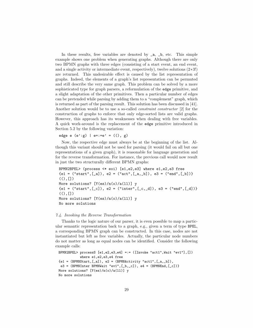
In these results, free variables are denoted by _a, _b, etc. This simpleexample shows one problem when generating graphs. Although there are onlytwo BPMN graphs with three edges (consisting of a start event, an end event,and a single activity or intermediate event, respectively), twelve solutions (2∗3!)are returned. This undesirable effect is caused by the list representation ofgraphs. Indeed, the elements of a graph’s list representation can be permutedand still describe the very same graph. This problem can be solved by a moresophisticated type for graph parsers, a reformulation of the edge primitive, anda slight adaptation of the other primitives. Then a particular number of edgescan be pretended while parsing by adding them to a “complement” graph, whichis returned as part of the parsing result. This solution has been discussed in [41].Another solution would be to use a so-called constraint constructor [2] for theconstruction of graphs to enforce that only edge-sorted lists are valid graphs.However, this approach has its weaknesses when dealing with free variables.A quick work-around is the replacement of the edge primitive introduced inSection 5.2 by the following variation:
edge e (e’:g) | e=:=e’ = ((), g)
Now, the respective edge must always be at the beginning of the list. Al-though this variant should not be used for parsing (it would fail on all but onerepresentations of a given graph), it is reasonable for language generation andfor the reverse transformation. For instance, the previous call would now resultin just the two structurally different BPMN graphs:
BPMN2BPEL> (process <* eoi) [e1,e2,e3] where e1,e2,e3 free{e1 = ("start",[_a]), e2 = ("act",[_a,_b]), e3 = ("end",[_b])}((),[])More solutions? [Y(es)/n(o)/a(ll)] y{e1 = ("start",[_c]), e2 = ("inter",[_c,_d]), e3 = ("end",[_d])}((),[])More solutions? [Y(es)/n(o)/a(ll)] yNo more solutions
7.4. Invoking the Reverse TransformationThanks to the logic nature of our parser, it is even possible to map a partic-
ular semantic representation back to a graph, e.g., given a term of type BPEL,a corresponding BPMN graph can be constructed. In this case, nodes are notinstantiated but left as free variables. Actually, the particular node numbersdo not matter as long as equal nodes can be identified. Consider the followingexample calls:BPMN2BPEL> processS [e1,e2,e3,e4] =:= ([Invoke "act1",Wait "ev1"],[])
where e1,e2,e3,e4 free
{e1 = (BPMNStart,[_a]), e2 = (BPMNActivity "act1",[_a,_b]),
e3 = (BPMNInter BPMNWait "ev1",[_b,_c]), e4 = (BPMNEnd,[_c])}
More solutions? [Y(es)/n(o)/a(ll)] y
No more solutions
29

BPMN2BPEL> processS [e1,e2,e3,e4,e5,e6] =:=
([Switch "c1" "c2" [Invoke "act1"] [Invoke "act2"]],[])
where e1,e2,e3,e4,e5,e6 free
{e1 = (BPMNStart,[_a]), e2 = (BPMNXGW "c1" "c2",[_a,_b,_c,_d]),
e3 = (BPMNActivity "act1",[_b,_e]), e4 = (BPMNActivity "act2",[_d,_f]),
e5 = (BPMNXGW _g _h,[_i,_e,_j,_f]), e6 = (BPMNEnd,[_j])}
More solutions? [Y(es)/n(o)/a(ll)] y
No more solutions
There are two problems with this approach though: First, the list permu-tation problem, already discussed in Section 7.3, occurs in this context again.Consequently, the other variation of edge has to be used in order to avoid re-dundant results. Alternatively, the operation findfirst could be used so thatonly the first result is returned (see also the definition of the operation main inSection 4). The second issue is that the number of edges needs to be known inadvance. This can be avoided by enumerating lists of free variables of increasinglength. For instance, a non-deterministic operation that returns an arbitrarylist of free variables can be defined as follows:
> anyList = []> anyList = x : anyList where x free
Now we can use anyList to guess some edge list es and pass it to processS:BPMN2BPEL> let es free in es =:= anyList &
processS es =:= ([Switch "c1" "c2" [Invoke "act1",Invoke "act2"]
[Invoke "act3",Wait "ev1"]],[])
{es = [(BPMNStart,[_a]),(BPMNXGW "c1" "c2",[_a,_b,_c,_d]),
(BPMNActivity "act1",[_b,_e]),(BPMNActivity "act2",[_e,_f]),
(BPMNActivity "act3",[_d,_g]),(BPMNInter BPMNWait "ev1",[_g,_h]),
(BPMNXGW _i _j,[_k,_f,_l,_h]),(BPMNEnd,[_l])]}
Thanks to the depth-first search strategy, which is the default strategy inmost Curry implementations, a graph with a smallest number of edges is com-puted as a first solution. However, if there is no solution, i.e., if a graph cor-responding to the given BPEL term does not exist, all graphs of increasing sizesare tried so that the computation does not terminate. This can only be avoidedby providing an upper bound on the size of the edge list. However, this isnot necessary for our transformation, because for every BPEL term there is acorresponding BPMN graph (but not vice versa).
7.5. Performance and BenchmarkingIn general, hypergraph parsing has a higher complexity than string parsing,
which is known to be less than O(n3). Actually, there are even context-freehypergraph languages where parsing is NP-complete [11]. Fortunately, mostpractically relevant languages are quite efficient to parse. The most efficientexisting hypergraph parser we are aware of is part of the DiaGen system [47].This parser uses dynamic programming techniques. Our functional logic parsersrely on backtracking, which is used in most Curry implementations, and, hence,
30

0
2
4
6
8
10
50 100 150 200 250 300 350 400
time
in s
ec
size of input hypergraph (number of edges)
Figure 15: Performance data for parsing activity chains
are not that efficient. Nevertheless, our proposed parsing approach can beapplied also to non-toy examples.
Figure 15 shows how graph parser combinators perform for BPMN hyper-graphs. We used input processes that contain only a chain of activities betweentheir start and end event, because that way it is possible to grow the inputhomogeneously. The measurement has been executed on low budget hardware(2GHz Celeron processor, 750MB RAM). As a compiler, MCC has been used.Encapsulated search via the operation findall ensures that all possible resultsare found and, thus, that the order of edges in the list-based graph representa-tion does not matter.
This benchmark shows that a process hypergraph with 200 successive acthyperedges created by a generator function can still be parsed in less than twoseconds. Moreover, when applied backwards as generators, Grappa parsers arevery efficient. Sierpinski triangles have been proposed as a case for performancecomparison of graph transformation tools [62]. With a Grappa parser, a regularSierpinski triangle of generation 12 with 531.441 = 312 edges has been generatedby MCC in 3 seconds on the same hardware as above. The resulting termcontains a large number of free variables. Of course, the parsing of Sierpinskitriangles is much more expensive.
Actually, graph parser combinators can even be used as a benchmark forCurry compilers. A precise case description and corresponding performancedata of MCC, PAKCS, and KiCS can be found in [41].
7.6. ScopeWe have shown by several scenarios the power of our approach in construct-
ing transformations between different modeling languages. Unfortunately, mostvisual languages are not context-free like structured process models and, thus,cannot be described by a plain hyperedge replacement grammar. Consequently,such languages can only be treated with restrictions or not at all.
31

Figure 2. Mapping a well-structured pattern C onto a BPEL structured activity and folding C into a singletask object tc attached with the resulting BPEL code.
In Figure 2(f) and (g), two patterns, repeat and repeat+while, represent repeat loops.Repeat loops are the opposite of while loops. A while loop (see while-pattern in Figure 2(e))evaluates the loop condition before the body of the loop is executed, so that the loop is neverexecuted if the condition is initially false. In a repeat loop, the condition is checked after thebody of the loop is executed, so that the loop is always executed at least once. In Figure 2(f),a repeat loop of task t1 is equivalent to a single execution of t1 followed by a while loop of t1.In Figure 2(g), a repeat loop of task t1 is combined with a while loop of task t2, and both share
9
Figure 16: Structured loops as treated in [51]
Regarding business process models, it is easy to add support for further ba-sic activities and structured constructs such as loops, cf. Figure 16. It wouldalso be possible to support gateways with more than two branches. However,non-context-free concepts such as message flow cannot be covered in a straight-forward way. Also quasi-structured processes, i.e., processes that can be trans-formed into structured ones [51], cannot directly be covered. Those need tobe preprocessed first. It would be interesting for future work to investigatewhether functional logic languages are equally well-suited for the implementa-tion of general purpose graph transformations. Purely functional languages havealready been applied in this domain [67] with reasonable success. Since func-tional logic languages provide even better abstractions for matching patterns ingraph structures, we think that they are a natural choice for this purpose.
Although the approach presented so far is limited, business process modelsare not the only language where it has been put to a good use. We have alsoapplied the Grappa framework to the visual languages of message sequencecharts, alligator eggs (a visual notation for lambda calculus [60]), and varioustree-like languages such as term graphs without sharing.
8. Related Work
The approach closest to our work is the PETE system, a declarative, purelylogic-based approach to transformations recently proposed by Schatz [55]. Sim-ilarly to our work, [55] considers a transformation as a relation and presentsmodels as structured terms. The proposed transformation mechanism allows aprecise and modular specification of transformations, which can be executed bya Prolog interpreter. An important benefit of this approach is that it is inte-
32

process :- start N1, flow N1 N2, end N2.
flow N1 N2 :- flElem N1 N2.flow N1 N2 :- flElem N1 N, flow N N2.
flElem N1 N2 :- act N1 N2.flElem N1 N2 :- inter N1 N2.flElem N1 N2 :- gw N1 N1t N1r N1b, flow N1t N2t,
gw N2l N2t N2 N2b, flow N1b N2b.
parseExample :- (start 1, gw 1 2 4 3, act 2 6,act 3 7, gw 5 6 8 7, end 8)-o process.
Figure 17: BPMN parser in Lolli [27]
grated into the popular Eclipse platform. More precisely, the Eclipse ModelingFramework (EMF) is used as a base, i.e., importers and exporters between EMFmodels and Prolog terms are provided. However, the resulting Prolog code ofa transformation is very verbose and at a rather low level of abstraction. Nomapping from a kind of visual transformation rule is provided as in our ap-proach. In order to get the accompanying reverse transformation in PETE, itis required to change the order of predicates on the right-hand side of the rules.The permutation problem caused by the list representation of sets in this arti-cle is avoided in PETE by a special set implementation based on ordered lists.PETE allows the transformation of a broader range of models, i.e., it is notrestricted to context-free languages. Although there might be many matches ofa pattern, backtracking is rarely needed because there are only very few “deadends”. Most of the time, committing to the first solution is sufficient, becausethe other solutions would yield the very same result via a different order ofmatches. PETE has been used to solve the model migration case [56] of thisyear’s transformation tool contest, i.e., the migration of UML activity diagramsfrom version 1.4 to version 2.2 [54].
There are also further logic-based approaches to support translations be-tween different structures. An early attempt for the bidirectional translationbetween abstract and pictorial data has been proposed in [37] where declarativerules written in Prolog have been used to specify the mappings. The idea ofrepresenting models by Prolog facts has also been used in [59] for the sake ofquerying models. In the context of business modeling, Prolog has been used forchecking syntactical properties of event-driven process chains [18].
Another interesting related observation is that parsing of visual languagescan be modeled and even executed in linear logic [16], a resource-oriented refine-ment of classical logic. For instance, in [6] the embedding of constraint multisetgrammars [36] into linear logic is discussed. However, it seems that hypergraphparsing can be modeled even more straightforwardly. Here, the edges of a hy-
33

pergraph can be mapped to facts that can be fed into a parser via so-calledlinear implication ((). During the proof, the parser consumes these facts andnone of them must be left at the end. Figure 17 shows a BPMN graph parserimplemented in the linear logic programming language Lolli [27] (the two differ-ent gateway types are not distinguished in this program). The main predicateof this program is parseExample, which analyzes the example graph shown inFigure 9. Not even a parser framework is required with this approach. Thegraph parser combinators described in this article also hide the remaining re-sources from the user. Their major benefits are their flexible application, thereversibility of the resulting parsers, and the possibility to compute semanticrepresentations in a straightforward way.
Another related approach is architectural design rewriting (ADR) [9]. Here,hypergraphs are used for representing the hierarchical architecture of a system.Hyperedge replacement grammars are used for building configurations in a waythat avoids, e.g., cyclic or broken flows. The involved graphs can often berepresented as terms. In this case, no parsing is required. Moreover, an algebraon these terms can be defined and exploited afterwards. Graph transformationrules can be used for manipulating configurations. Then, it has to be proventhat the rules of the underlying algebra are preserved. The developers of theADR approach also admit that not everything can be modeled with ADR, butif a part of a problem can be captured, ADR provides an elegant way to reasonabout and reconfigure the system.
Regarding error correction, the purely functional HUT library [61] needs tobe mentioned. It supports the construction of (string) parser combinators withpowerful error correction mechanisms. There, a parser does never fail but ratherconstructs a minimal sequence of correction steps. We have shown how func-tional logic graph parser combinators provide specific kinds of error handling.Redundant edges, for instance, may just remain at the end. This is alreadyquite powerful, since, in contrast to strings, graphs are sets of components, i.e.,no particular order on edges or nodes is imposed. Thus, it does not matterwhere the redundant components are placed. Furthermore, due to their logicnature, graph parser combinators allow to deal with further errors in a conve-nient way, e.g., they can complete incomplete graphs. An alternative approachfor hypergraph completion has been proposed in [38]. This approach is basedon dynamic programming.
Other approaches for the specification of bidirectional transformations in-clude Schurr’s triple graph grammars [57] and Pierce’s lense combinators [14]that even support the synchronization of evolving models. However, whereasthe former requires much more specification effort than our approach, the latteris quite restricted in its applicability.
Finally, the competing solutions of the GraBaTs 2009 synthesis case have tobe mentioned as related work, of course. The case was won by a plain Java solu-tion that covered the most comprehensive subset of BPMN [15]. The best gen-eral transformation approaches have been GROOVE, MoTMoT, and Grappa.The evaluation matrix can be found at http://is.tm.tue.nl/staff/pvgorp/events/grabats2009/synthesis-evaluation.pdf (accessed on 2010-07-30).
34

9. Conclusion
In this article, we have proposed a novel approach to construct a bidirectionaltransformation between BPMN and BPEL and discussed its potential applica-bility. Both languages and the transformation in-between are highly relevant.Our solution is based on functional logic programming techniques and imple-mented using the multi-paradigm declarative language Curry. The proposedtransformation relies on an extended version of the graph parser combinatorframework Grappa, which was originally introduced in [40]. Grappa requiresdiagrams—process models in this case—to be represented by hypergraphs. Thearticle has shown that hyperedge replacement grammars, a context-free devicefor the specification of graph languages, can be translated into graph parsersin a systematic way. The resulting parsers closely resemble the grammar rules.A parser for a significant subset of the BPMN language (structured processmodels) has been realized that way.
Moreover, this case study has shown the flexibility of graph parser combi-nators in the construction of semantic representations for the first time. Tothis end, Grappa has been extended by typed hypergraphs. With the resultingtransformation, BPMN graphs cannot only be derived backwards from a givenBPEL structure, but it is also possible to complete partial process models or touse the parser for language generation. Since the whole Grappa framework areonly a few dozen lines of code, this article contains the complete code for run-ning the transformations. Actually, the article’s source text is a literate Curryprogram and, as such, directly executable.
Caballero and Lopez-Fraguas [10] have recognized the benefits of functionallogic languages for building string parsers. However, in the context of graphsthey are even more useful. Graph parser combinators make heavy use of keyfeatures of both the functional and the logic programming approach: Higher-order functions allow the treatment of parsers as first class citizens, and non-determinism and free variables are beneficial for dealing with errors and incom-plete information. Therefore, graph parser combinators are also an interestingand promising application area of functional logic programming and, at thesame time, an example how logic programming techniques advance the state-of-the-art in visual languages.
For future work, it would be useful to investigate how functional logic lan-guages can be exploited to implement more general graph transformation sys-tems to overcome the limitations in scope of the approach developed so far.Moreover, the transformation proposed in this article constructs the term rep-resentations of models from scratch again and again. It would also be interestingto see how functional logic techniques could be used in order to support the reuseof existing structures, i.e., allow for model synchronization.
To make this research reproducible, an installation of the presented solu-tion is available as a SHARE virtual machine (Sharing Hosted AutonomousResearch Environments). SHARE images can be accessed via http://is.tm.tue.nl/staff/pvgorp/share/ (accessed on 2010-07-30). The machine is calledUbuntu-8.10_GB9_grappa-bpm.vdi.
35

[1] Antoy, S., Echahed, R., Hanus, M., 2000. A needed narrowing strategy.Journal of the ACM 47 (4), 776–822.
[2] Antoy, S., Hanus, M., 2002. Functional logic design patterns. In: Proc. ofthe 6th International Symposium on Functional and Logic Programming.Vol. 2441 of LNCS. Springer-Verlag, pp. 67–87.
[3] Antoy, S., Hanus, M., 2010. Functional logic programming. Communica-tions of the ACM 53 (4), 74–85.
[4] Arias, E. J. G., Carballo, J. M., Poza, J. M. R., 2007. A proposal for dis-equality constraints in Curry. Electronic Notes in Theoretical ComputerScience 177, 269–285, proc. of the 15th International Workshop on Func-tional and (Constraint) Logic Programming.
[5] Bardohl, R., Minas, M., Taentzer, G., Schurr, A., 1999. Application ofgraph transformation to visual languages. In: Handbook of Graph Gram-mars and Computing by Graph Transformation. Vol. 2: Applications, Lan-guages, and Tools. World Scientific, pp. 105–180.
[6] Bottoni, P., Meyer, B., Marriott, K., Parisi-Presicce, F., 2001. Deductiveparsing of visual languages. In: Proc. of the 4th International Conference onLogical Aspects of Computational Linguistics. Vol. 2099 of LNCS. Springer-Verlag, pp. 79–94.
[7] Braßel, B., Hanus, M., Muller, M., 2008. High-level database programmingin Curry. In: Proc. of the Tenth International Symposium on PracticalAspects of Declarative Languages. Vol. 4902 of LNCS. Springer-Verlag, pp.316–332.
[8] Braßel, B., Huch, F., 2009. The Kiel Curry system KiCS. In: Applicationsof Declarative Programming and Knowledge Management. Vol. 5437 ofLNCS. Springer-Verlag, pp. 195–205.
[9] Bruni, R., Lafuente, A. L., Montanari, U., 2009. Hierarchical design rewrit-ing with Maude. Electronic Notes in Theoretical Computer Science 238 (3),45 – 62, proceedings of the Seventh International Workshop on RewritingLogic and its Applications.
[10] Caballero, R., Lopez-Fraguas, F. J., 1999. A functional-logic perspective ofparsing. In: Proc. of the 4th Fuji International Symposium on Functionaland Logic Programming. Vol. 1722 of LNCS. Springer-Verlag, pp. 85–99.
[11] Drewes, F., Habel, A., Kreowski, H.-J., 1997. Hyperedge replacement graphgrammars. In: Handbook of Graph Grammars and Computing by GraphTransformation. Vol. I: Foundations. World Scientific, Ch. 2, pp. 95–162.
[12] Dumas, M., 2009. Case study: BPMN to BPEL model transfor-mation. http://is.ieis.tue.nl/staff/pvgorp/events/grabats2009/cases/grabats2009synthesis.pdf (accessed on 2010-07-11).
36

[13] Fischer, S., 2005. A functional logic database library. In: Proc. of the ACMSIGPLAN 2005 Workshop on Curry and Functional Logic Programming.ACM Press, pp. 54–59.
[14] Foster, J. N., Greenwald, M. B., Moore, J. T., Pierce, B. C., Schmitt, A.,2005. Combinators for bi-directional tree transformations: A linguistic ap-proach to the view update problem. In: Proc. of the 32nd ACM Symposiumon Principles of Programming Languages. ACM, pp. 233–246.
[15] Garcıa-Banuelos, L., 2009. Translating BPMN models to BPEL code. Ac-cepted as a solution for the synthesis case of the GraBaTs 2009 tool contest.
[16] Girard, J.-Y., 1987. Linear logic. Theoretical Computer Science 50, 1–102.
[17] Gonzalez-Moreno, J., Hortala-Gonzalez, M., Lopez-Fraguas, F., Rodrıguez-Artalejo, M., 1999. An approach to declarative programming based on arewriting logic. Journal of Logic Programming 40, 47–87.
[18] Gruhn, V., Laue, R., 2006. Validierung syntaktischer und anderer EPK-Eigenschaften mit PROLOG. In: Proc. des 5. GI Workshops uberGeschaftsprozessmanagement mit Ereignisgesteuerten Prozessketten. Vol.224 of CEUR Workshop Proceedings. CEUR-WS.org, pp. 69—85.
[19] Gruhn, V., Laue, R., 2007. What business process modelers can learn fromprogrammers. Science of Computer Programming 65 (1), 4–13.
[20] Hanus, M., 2000. A functional logic programming approach to graphicaluser interfaces. In: Proc. of the Second International Workshop on PracticalAspects of Declarative Languages. Vol. 1753 of LNCS. Springer-Verlag, pp.47–62.
[21] Hanus, M., 2001. High-level server side web scripting in Curry. In: Proc.of the Third International Symposium on Practical Aspects of DeclarativeLanguages. Vol. 1990 of LNCS. Springer-Verlag, pp. 76–92.
[22] Hanus, M., 2006. Curry: An Integrated Functional Logic Language (Version0.8.2). http://www.curry-language.org/ (accessed on 2010-07-11).
[23] Hanus, M., 2006. Type-oriented construction of web user interfaces. In:Proc. of the 8th ACM SIGPLAN International Conference on Principlesand Practice of Declarative Programming. ACM Press, pp. 27–38.
[24] Hanus, M., 2007. Multi-paradigm declarative languages. In: Proc. of the23rd International Conference on Logic Programming. Vol. 4670 of LNCS.Springer-Verlag, pp. 45–75.
[25] Hanus, M., Antoy, S., Braßel, B., Engelke, M., Hoppner, K., Koj, J.,Niederau, P., Sadre, R., Steiner, F., 2010. PAKCS: The Portland AachenKiel Curry System. Available at http://www.informatik.uni-kiel.de/
~pakcs/ (accessed on 2010-07-11).
37

[26] Hanus, M., Koschnicke, S., 2010. An ER-based framework for declarativeweb programming. In: Proc. of the 12th International Symposium on Prac-tical Aspects of Declarative Languages. Vol. 5937 of LNCS. Springer-Verlag,pp. 201–216.
[27] Hodas, J. S., Miller, D., 1994. Logic programming in a fragment of intu-itionistic linear logic. Information and Computation 110 (2), 327–365.
[28] Hutton, G., 1992. Higher-order functions for parsing. Journal of FunctionalProgramming 2 (3), 323–343.
[29] Johnson, R., Pearson, D., Pingali, K., 1994. The program structure tree:Computing control regions in linear time. In: Proc. of the ACM SIGPLANConference on Programming Language Design and Implementation. ACMPress, pp. 171–185.
[30] Johnson, S. C., 1975. Yacc: Yet another compiler compiler. Tech. Rep. 32,Bell Laboratories, Murray Hill, New Jersey.
[31] Kasami, T., 1965. An efficient recognition and syntax-analysis algorithmfor context free languages. Scientific Report AF CRL-65-758, Air ForceCambridge Research Laboratory.
[32] Knuth, D. E., 1968. Semantics of context-free languages. Theory of Com-puting Systems 2 (2), 127–145.
[33] Knuth, D. E., 1984. Literate programming. The Computer Journal 27 (2),97–111.
[34] Leijen, D., Meijer, E., 2001. Parsec: Direct style monadic parser combina-tors for the real world. Tech. Rep. UU-CS-2001-27, Department of Com-puter Science, Universiteit Utrecht.
[35] Lux, W., 1999. Implementing encapsulated search for a lazy functional logiclanguage. In: Proc. of the 4th Fuji International Symposium on Functionaland Logic Programming. Vol. 1722 of LNCS. Springer-Verlag, pp. 100–113.
[36] Marriott, K., 1994. Constraint multiset grammars. In: Proc. of the 1994IEEE Symposium on Visual Languages. IEEE, pp. 118–125.
[37] Matsuoka, S., Takahashi, S., Kamada, T., Yonezawa, A., 1992. A generalframework for bidirectional translation between abstract and pictorial data.ACM Transactions on Information Systems 10 (4), 408–437.
[38] Mazanek, S., Maier, S., Minas, M., 2008. An algorithm for hypergraphcompletion according to hyperedge replacement grammars. In: Proc. ofthe 4th International Conference on Graph Transformations. Vol. 5214 ofLNCS. Springer-Verlag, pp. 39–53.
38

[39] Mazanek, S., Maier, S., Minas, M., 2008. Auto-completion for diagrameditors based on graph grammars. In: Proc. of the 2008 IEEE Symposiumon Visual Languages and Human-Centric Computing. IEEE, pp. 242–245.
[40] Mazanek, S., Minas, M., 2008. Functional-logic graph parser combinators.In: Proc. of the 19th International Conference on Rewriting Techniquesand Applications. Vol. 5117 of LNCS. Springer-Verlag, pp. 261–275.
[41] Mazanek, S., Minas, M., 2008. Graph parser combinators: A challengefor Curry-compilers. In: Hanus, M., Fischer, S. (Eds.), 25. Workshop derGI-Fachgruppe “Programmiersprachen und Rechenkonzepte”. Christian-Albrechts-Universitat zu Kiel, pp. 55–66, Tech. Rep. 0811.
[42] Mazanek, S., Minas, M., 2009. Business process models as a showcase forsyntax-based assistance in diagram editors. In: Proc. of the 12th Interna-tional Conference on Model Driven Engineering Languages and Systems.Vol. 5795 of LNCS. Springer-Verlag, pp. 322–336.
[43] Mazanek, S., Minas, M., 2009. Transforming BPMN to BPEL using parsingand attribute evaluation with respect to a hypergraph grammar. Acceptedas a solution for the synthesis case of the GraBaTs 2009 tool contest.
[44] Mendling, J., Reijers, H., van der Aalst, W., 2009. Seven process modelingguidelines (7pmg). Information and Software Technology 52 (2), 127–136.
[45] Minas, M., 2000. Creating semantic representations of diagrams. In: Proc.of the International Workshop on Applications of Graph Transformationswith Industrial Relevance. Vol. 1779. Springer-Verlag, pp. 209–224.
[46] Minas, M., 2000. Hypergraphs as a uniform diagram representation model.In: Proc. of the 6th International Workshop on Theory and Application ofGraph Transformations. Vol. 1764 of LNCS. Springer-Verlag, pp. 281–295.
[47] Minas, M., 2002. Concepts and realization of a diagram editor generatorbased on hypergraph transformation. Science of Computer Programming44 (2), 157–180.
[48] OASIS, 2007. Web Services Business Process Execution Language Ver-sion 2.0. http://docs.oasis-open.org/wsbpel/2.0/wsbpel-v2.0.pdf(accessed on 2010-07-11). Actually, the transformation of this article doesnot generate BPEL 2.0 but still BPEL 1.1.
[49] Object Management Group, 2009. Business Process Modeling Notation(BPMN). http://www.omg.org/spec/BPMN/1.2/ (accessed on 2010-07-11).
[50] Ouyang, C., Dumas, M., Breutel, S., ter Hofstede, A., 2006. Translatingstandard process models to BPEL. In: Proc. of the 18th InternationalConference on Advanced Information Systems Engineering. Vol. 4001 ofLNCS. Springer-Verlag, pp. 417–432.
39

[51] Ouyang, C., Dumas, M., ter Hofstede, A., van der Aalst, W., 2007. Pattern-based translation of BPMN process models to BPEL web services. Inter-national Journal of Web Services Research 5 (1), 42–62.
[52] Peyton Jones, S., 2003. Haskell 98, Language and Libraries, The RevisedReport. Cambridge University Press.
[53] Pratt, T. W., 1971. Pair grammars, graph languages and string-to-graphtranslations. Journal of Computer and System Sciences 5 (6), 560–595.
[54] Rose, L. M., Kolovos, D. S., Paige, R. F., Polack, F. A., 2010. Model migra-tion case for TTC 2010. http://is.ieis.tue.nl/staff/pvgorp/events/TTC2010/cases/ttc2010_submission_2_v2010-04-22.pdf (accessed on2010-07-11).
[55] Schatz, B., 2009. Formalization and rule-based transformation of EMFEcore-based models. In: Proc. of the First International Conference onSoftware Language Engineering. Vol. 5452 of LNCS. Springer-Verlag, pp.227–244.
[56] Schatz, B., 2010. UML model migration with PETE. http://is.ieis.tue.nl/staff/pvgorp/events/TTC2010/submissions/final/pete.pdf(accessed on 2010-07-11).
[57] Schurr, A., 1994. Specification of graph translators with triple graph gram-mars. In: Proc. of the 20th International Workshop on Graph-TheoreticConcepts in Computer Science. Vol. 903 of LNCS. Springer-Verlag, pp.151–163.
[58] Slagle, J., 1974. Automated theorem-proving for theories with simplifiers,commutativity, and associativity. Journal of the ACM 21 (4), 622–642.
[59] Storrle, H., 2007. A PROLOG-based approach to representing and queryingsoftware engineering models. In: Proc. of the VLL 2007 Workshop on VisualLanguages and Logic. Vol. 274 of CEUR Workshop Proceedings. CEUR-WS.org, pp. 71–83.
[60] Strobl, T., Minas, M., 2009. Implementing an animated lambda-calculus.In: Proc. of the Workshop on Visual Languages and Logic. Vol. 510 ofCEUR Workshop Proceedings. CEUR-WS.org.
[61] Swierstra, S. D., Azero Alcocer, P. R., 1999. Fast, error correcting parsercombinators: a short tutorial. In: Proc. of the 26th Seminar on CurrentTrends in Theory and Practice of Informatics. Vol. 1725 of LNCS. Springer-Verlag, pp. 111–129.
[62] Taentzer, G., Biermann, E., Bisztray, D., Bohnet, B., Boneva, I., Boronat,A., Geiger, L., Geiß, R., Horvath, A., Kniemeyer, O., Mens, T., Ness, B.,Plump, D., Vajk, T., 2008. Generation of Sierpinski triangles: A case study
40

for graph transformation tools. In: Proc. of the Third International Sympo-sium on Applications of Graph Transformations with Industrial Relevance.Vol. 5088 of LNCS. Springer-Verlag, pp. 514–539.
[63] Tanaka, T., 1991. Definite-clause set grammars: a formalism for problemsolving. Journal of Logic Programming 10 (1), 1–17.
[64] Vanhatalo, J., Volzer, H., Koehler, J., 2008. The refined process structuretree. In: Proc. of the 6th International Conference on Business ProcessManagement. Vol. 5240 of LNCS. Springer-Verlag, pp. 100–115.
[65] Wadler, P., 1985. How to replace failure by a list of successes: A methodfor exception handling, backtracking, and pattern matching in lazy func-tional languages. In: Functional Programming Languages and ComputerArchitecture. Vol. 201 of LNCS. Springer-Verlag, pp. 113–128.
[66] Wallace, M., 2008. Partial parsing: Combining choice with commitment.In: Proc. of the 19th International Workshop on the Implementation andApplication of Functional Languages. Vol. 5083 of LNCS. Springer-Verlag,pp. 93–110.
[67] West, S., Kahl, W., 2009. A generic graph transformation, visualisation,and editing framework in Haskell. In: Proc. of the 8th International Work-shop on Graph Transformation and Visual Modeling Techniques. Vol. 18 ofElectronic Communications of the EASST. European Association of Soft-ware Science and Technology.
41

Appendix A. Generating BPEL-XML from Constructor Terms
For the sake of completeness, we provide an implementation of the generationof BPEL-XML from BPEL terms as defined in this article. There are also higher-level approaches for the generation of XML in functional languages but thissimple solution is sufficient for our purposes.
> bpel2xml :: BPEL → String> bpel2xml f = "<process>\n" ++> indent 1 (seq2xml f) ++> "</process>\n"
> seq2xml [e] = bpelComp2xml e> seq2xml es@(_:_:_) = "<sequence>\n" ++> indent 1 (concatMap bpelComp2xml es) ++> "</sequence>\n"
> bpelComp2xml (Invoke name) = "<invoke name=\""++name++"\"/>\n"> bpelComp2xml (Wait name) = "<wait name=\""++name++"\"/>\n"> bpelComp2xml (Receive name) = "<receive name=\""++name++"\"/>\n"> bpelComp2xml (Flow f1 f2) = "<flow>\n" ++> indent 1 (seq2xml f1) ++> indent 1 (seq2xml f2) ++> "</flow>\n"> bpelComp2xml (Switch c1 c2 f1 f2) => "<switch>\n" ++> " <case cond=\""++c1++"\">\n" ++> indent 1 (seq2xml f1) ++> " </case>\n" ++> " <case cond=\""++c2++"\">\n" ++> indent 1 (seq2xml f2) ++> " </case>\n" ++> "</switch>\n"
> --lines and unlines are inverse functions for switching between a> --text with line breaks ’\n’ and the respective list of lines> indent n s = unlines (map (nblanks++) (lines s))> --construct a string of n blanks> where nblanks = take n (repeat ’ ’)
42