Consolidated* Valve Sizing and Selection - … Valves Sizing and Selection | 5 Formula Symbols Prior...
28
GE Oil & Gas Consolidated* Valve Sizing and Selection GE Data Classification : Public
Transcript of Consolidated* Valve Sizing and Selection - … Valves Sizing and Selection | 5 Formula Symbols Prior...
GE Oil & Gas
Consolidated*
Valve Sizing and Selection
GE Data Classification : Public

2 | GE Oil & Gas © 2015 General Electric Company. All rights reserved.
Consolidated Valves Sizing and Selection | 3© 2015 General Electric Company. All rights reserved.
Table of ContentsIntroduction ..........................................................................................................................................................................4
Formula Symbols ...............................................................................................................................................................5
Set Pressure and Overpressure ..................................................................................................................................6
API Sizing Formulas ..........................................................................................................................................................8
ASME Sizing Formulas .....................................................................................................................................................9
Correction Factors ............................................................................................................................................................11
Fluid Properties ...................................................................................................................................................................14
API Standard Orifice Areas
1900 .......................................................................................................................................................................16
2900 .......................................................................................................................................................................17
3900 and 4900 ..................................................................................................................................................18
19000 ....................................................................................................................................................................19
1982 and 13900 ...............................................................................................................................................20
Superheat Correction Factors ....................................................................................................................................21
Rupture Disk Combination ............................................................................................................................................23
API Fire Sizing ......................................................................................................................................................................24
4 | GE Oil & Gas © 2015 General Electric Company. All rights reserved.
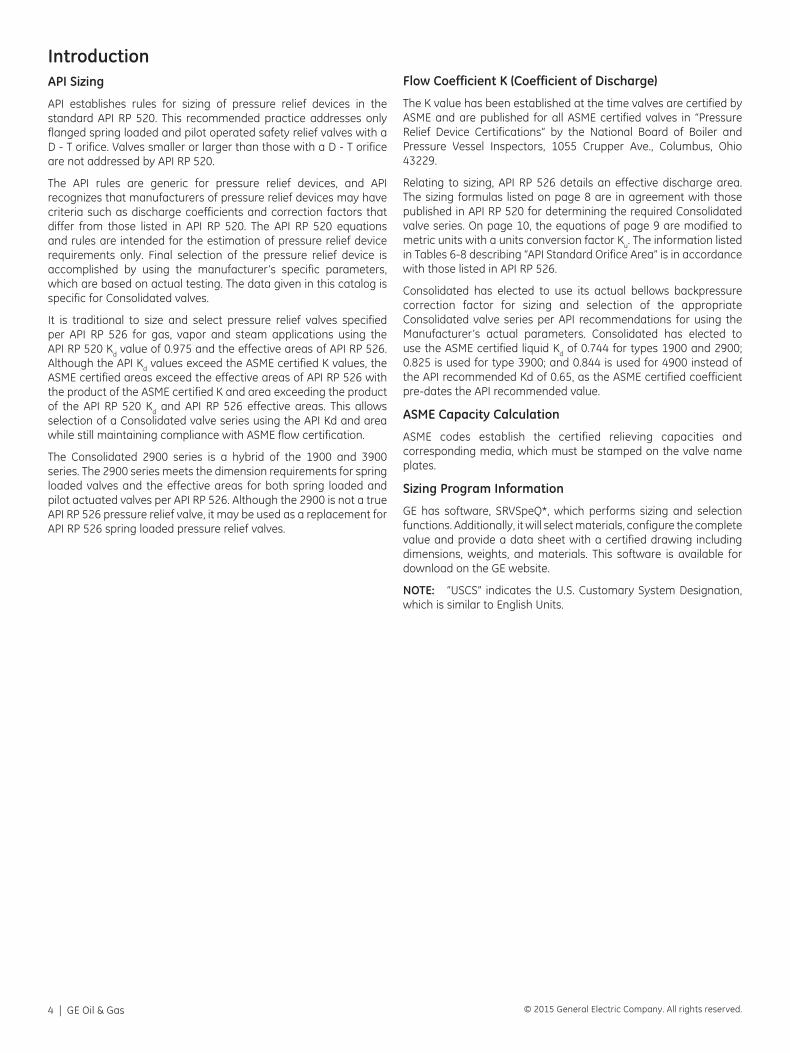
IntroductionAPI Sizing
API establishes rules for sizing of pressure relief devices in the standard API RP 520. This recommended practice addresses only flanged spring loaded and pilot operated safety relief valves with a D - T orifice. Valves smaller or larger than those with a D - T orifice are not addressed by API RP 520.
The API rules are generic for pressure relief devices, and API recognizes that manufacturers of pressure relief devices may have criteria such as discharge coefficients and correction factors that differ from those listed in API RP 520. The API RP 520 equations and rules are intended for the estimation of pressure relief device requirements only. Final selection of the pressure relief device is accomplished by using the manufacturer’s specific parameters, which are based on actual testing. The data given in this catalog is specific for Consolidated valves.
It is traditional to size and select pressure relief valves specified per API RP 526 for gas, vapor and steam applications using the API RP 520 Kd value of 0.975 and the effective areas of API RP 526. Although the API Kd values exceed the ASME certified K values, the ASME certified areas exceed the effective areas of API RP 526 with the product of the ASME certified K and area exceeding the product of the API RP 520 Kd and API RP 526 effective areas. This allows selection of a Consolidated valve series using the API Kd and area while still maintaining compliance with ASME flow certification.
The Consolidated 2900 series is a hybrid of the 1900 and 3900 series. The 2900 series meets the dimension requirements for spring loaded valves and the effective areas for both spring loaded and pilot actuated valves per API RP 526. Although the 2900 is not a true API RP 526 pressure relief valve, it may be used as a replacement for API RP 526 spring loaded pressure relief valves.
Flow Coefficient K (Coefficient of Discharge)
The K value has been established at the time valves are certified by ASME and are published for all ASME certified valves in “Pressure Relief Device Certifications” by the National Board of Boiler and Pressure Vessel Inspectors, 1055 Crupper Ave., Columbus, Ohio 43229.
Relating to sizing, API RP 526 details an effective discharge area. The sizing formulas listed on page 8 are in agreement with those published in API RP 520 for determining the required Consolidated valve series. On page 10, the equations of page 9 are modified to metric units with a units conversion factor Ku. The information listed in Tables 6-8 describing “API Standard Orifice Area” is in accordance with those listed in API RP 526.
Consolidated has elected to use its actual bellows backpressure correction factor for sizing and selection of the appropriate Consolidated valve series per API recommendations for using the Manufacturer’s actual parameters. Consolidated has elected to use the ASME certified liquid Kd of 0.744 for types 1900 and 2900; 0.825 is used for type 3900; and 0.844 is used for 4900 instead of the API recommended Kd of 0.65, as the ASME certified coefficient pre-dates the API recommended value.
ASME Capacity Calculation
ASME codes establish the certified relieving capacities and corresponding media, which must be stamped on the valve name plates.
Sizing Program Information
GE has software, SRVSpeQ*, which performs sizing and selection functions. Additionally, it will select materials, configure the complete value and provide a data sheet with a certified drawing including dimensions, weights, and materials. This software is available for download on the GE website.
NOTE: “USCS” indicates the U.S. Customary System Designation, which is similar to English Units.
Consolidated Valves Sizing and Selection | 5© 2015 General Electric Company. All rights reserved.
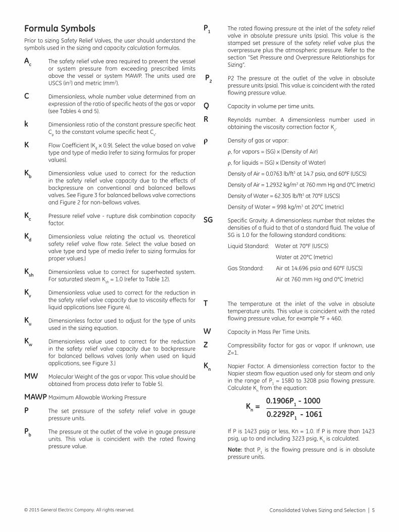
Formula SymbolsPrior to sizing Safety Relief Valves, the user should understand the symbols used in the sizing and capacity calculation formulas.
Ac The safety relief valve area required to prevent the vessel or system pressure from exceeding prescribed limits above the vessel or system MAWP. The units used are USCS (in2) and metric (mm2).
C Dimensionless, whole number value determined from an expression of the ratio of specific heats of the gas or vapor (see Tables 4 and 5).
k Dimensionless ratio of the constant pressure specific heat Cp to the constant volume specific heat Cv.
K Flow Coefficient (Kd x 0.9). Select the value based on valve type and type of media (refer to sizing formulas for proper values).
Kb Dimensionless value used to correct for the reduction in the safety relief valve capacity due to the effects of backpressure on conventional and balanced bellows valves. See Figure 3 for balanced bellows valve corrections and Figure 2 for non-bellows valves.
Kc Pressure relief valve - rupture disk combination capacity factor.
Kd Dimensionless value relating the actual vs. theoretical safety relief valve flow rate. Select the value based on valve type and type of media (refer to sizing formulas for proper values.)
Ksh Dimensionless value to correct for superheated system. For saturated steam Ksh = 1.0 (refer to Table 12).
Kv Dimensionless value used to correct for the reduction in the safety relief valve capacity due to viscosity effects for liquid applications (see Figure 4).
Ku Dimensionless factor used to adjust for the type of units used in the sizing equation.
Kw Dimensionless value used to correct for the reduction in the safety relief valve capacity due to backpressure for balanced bellows valves (only when used on liquid applications, see Figure 3.)
MW Molecular Weight of the gas or vapor. This value should be obtained from process data (refer to Table 5).
MAWP Maximum Allowable Working Pressure
P The set pressure of the safety relief valve in gauge pressure units.
Pb The pressure at the outlet of the valve in gauge pressure units. This value is coincident with the rated flowing pressure value.
P1 The rated flowing pressure at the inlet of the safety relief valve in absolute pressure units (psia). This value is the stamped set pressure of the safety relief valve plus the overpressure plus the atmospheric pressure. Refer to the section “Set Pressure and Overpressure Relationships for Sizing”.
P2 P2 The pressure at the outlet of the valve in absolute pressure units (psia). This value is coincident with the rated flowing pressure value.
Q Capacity in volume per time units.
R Reynolds number. A dimensionless number used in obtaining the viscosity correction factor Kv.
ρ Density of gas or vapor:
ρ, for vapors = (SG) x (Density of Air)
ρ, for liquids = (SG) x (Density of Water)
Density of Air = 0.0763 lb/ft3 at 14.7 psia, and 60°F (USCS)
Density of Air = 1.2932 kg/m3 at 760 mm Hg and 0°C (metric)
Density of Water = 62.305 lb/ft3 at 70°F (USCS)
Density of Water = 998 kg/m3 at 20°C (metric)
SG Specific Gravity. A dimensionless number that relates the densities of a fluid to that of a standard fluid. The value of SG is 1.0 for the following standard conditions:
Liquid Standard: Water at 70°F (USCS)
Water at 20°C (metric)
Gas Standard: Air at 14.696 psia and 60°F (USCS)
Air at 760 mm Hg and 0°C (metric)
T The temperature at the inlet of the valve in absolute temperature units. This value is coincident with the rated flowing pressure value, for example °F + 460.
W Capacity in Mass Per Time Units.
Z Compressibility factor for gas or vapor. If unknown, use Z=1.
Kn Napier Factor. A dimensionless correction factor to the Napier steam flow equation used only for steam and only in the range of P1 = 1580 to 3208 psia flowing pressure. Calculate Kn from the equation:
Kn = 0.1906P1 - 1000
0.2292P1 - 1061
If P is 1423 psig or less, Kn = 1.0. If P is more than 1423 psig, up to and including 3223 psig, Kn is calculated.
Note: that P1 is the flowing pressure and is in absolute pressure units.
6 | GE Oil & Gas © 2015 General Electric Company. All rights reserved.
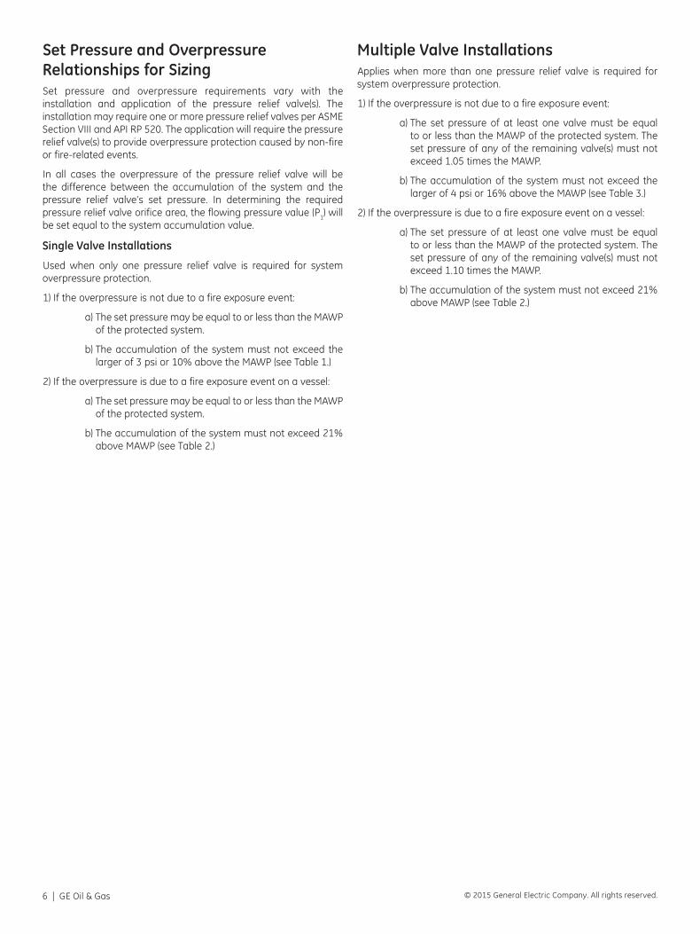
Set Pressure and Overpressure Relationships for SizingSet pressure and overpressure requirements vary with the installation and application of the pressure relief valve(s). The installation may require one or more pressure relief valves per ASME Section VIII and API RP 520. The application will require the pressure relief valve(s) to provide overpressure protection caused by non-fire or fire-related events.
In all cases the overpressure of the pressure relief valve will be the difference between the accumulation of the system and the pressure relief valve’s set pressure. In determining the required pressure relief valve orifice area, the flowing pressure value (P1) will be set equal to the system accumulation value.
Single Valve Installations
Used when only one pressure relief valve is required for system overpressure protection.
1) If the overpressure is not due to a fire exposure event:
a) The set pressure may be equal to or less than the MAWP of the protected system.
b) The accumulation of the system must not exceed the larger of 3 psi or 10% above the MAWP (see Table 1.)
2) If the overpressure is due to a fire exposure event on a vessel:
a) The set pressure may be equal to or less than the MAWP of the protected system.
b) The accumulation of the system must not exceed 21% above MAWP (see Table 2.)
Multiple Valve InstallationsApplies when more than one pressure relief valve is required for system overpressure protection.
1) If the overpressure is not due to a fire exposure event:
a) The set pressure of at least one valve must be equal to or less than the MAWP of the protected system. The set pressure of any of the remaining valve(s) must not exceed 1.05 times the MAWP.
b) The accumulation of the system must not exceed the larger of 4 psi or 16% above the MAWP (see Table 3.)
2) If the overpressure is due to a fire exposure event on a vessel:
a) The set pressure of at least one valve must be equal to or less than the MAWP of the protected system. The set pressure of any of the remaining valve(s) must not exceed 1.10 times the MAWP.
b) The accumulation of the system must not exceed 21% above MAWP (see Table 2.)
Consolidated Valves Sizing and Selection | 7© 2015 General Electric Company. All rights reserved.
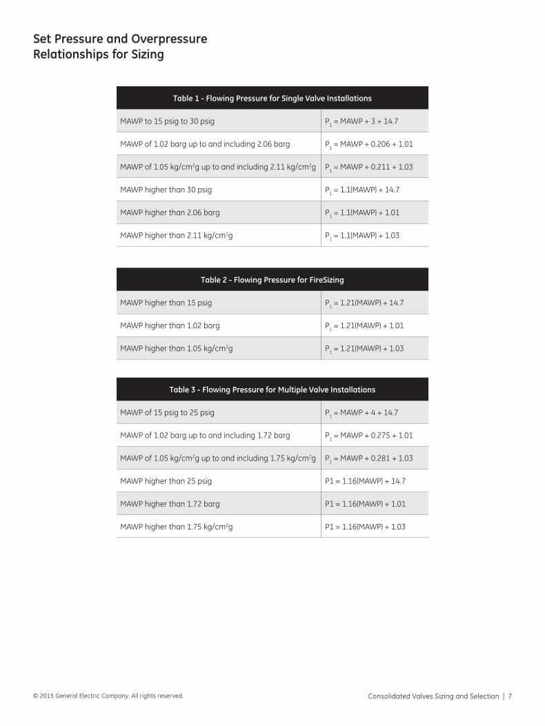
Set Pressure and Overpressure Relationships for Sizing
Table 1 - Flowing Pressure for Single Valve Installations
MAWP to 15 psig to 30 psig P1 = MAWP + 3 + 14.7
MAWP of 1.02 barg up to and including 2.06 barg P1 = MAWP + 0.206 + 1.01
MAWP of 1.05 kg/cm2g up to and including 2.11 kg/cm2g P1 = MAWP + 0.211 + 1.03
MAWP higher than 30 psig P1 = 1.1(MAWP) + 14.7
MAWP higher than 2.06 barg P1 = 1.1(MAWP) + 1.01
MAWP higher than 2.11 kg/cm2g P1 = 1.1(MAWP) + 1.03
Table 2 - Flowing Pressure for FireSizing
MAWP higher than 15 psig P1 = 1.21(MAWP) + 14.7
MAWP higher than 1.02 barg P1 = 1.21(MAWP) + 1.01
MAWP higher than 1.05 kg/cm2g P1 = 1.21(MAWP) + 1.03
Table 3 - Flowing Pressure for Multiple Valve Installations
MAWP of 15 psig to 25 psig P1 = MAWP + 4 + 14.7
MAWP of 1.02 barg up to and including 1.72 barg P1 = MAWP + 0.275 + 1.01
MAWP of 1.05 kg/cm2g up to and including 1.75 kg/cm2g P1 = MAWP + 0.281 + 1.03
MAWP higher than 25 psig P1 = 1.16(MAWP) + 14.7
MAWP higher than 1.72 barg P1 = 1.16(MAWP) + 1.01
MAWP higher than 1.75 kg/cm2g P1 = 1.16(MAWP) + 1.03
8 | GE Oil & Gas © 2015 General Electric Company. All rights reserved.
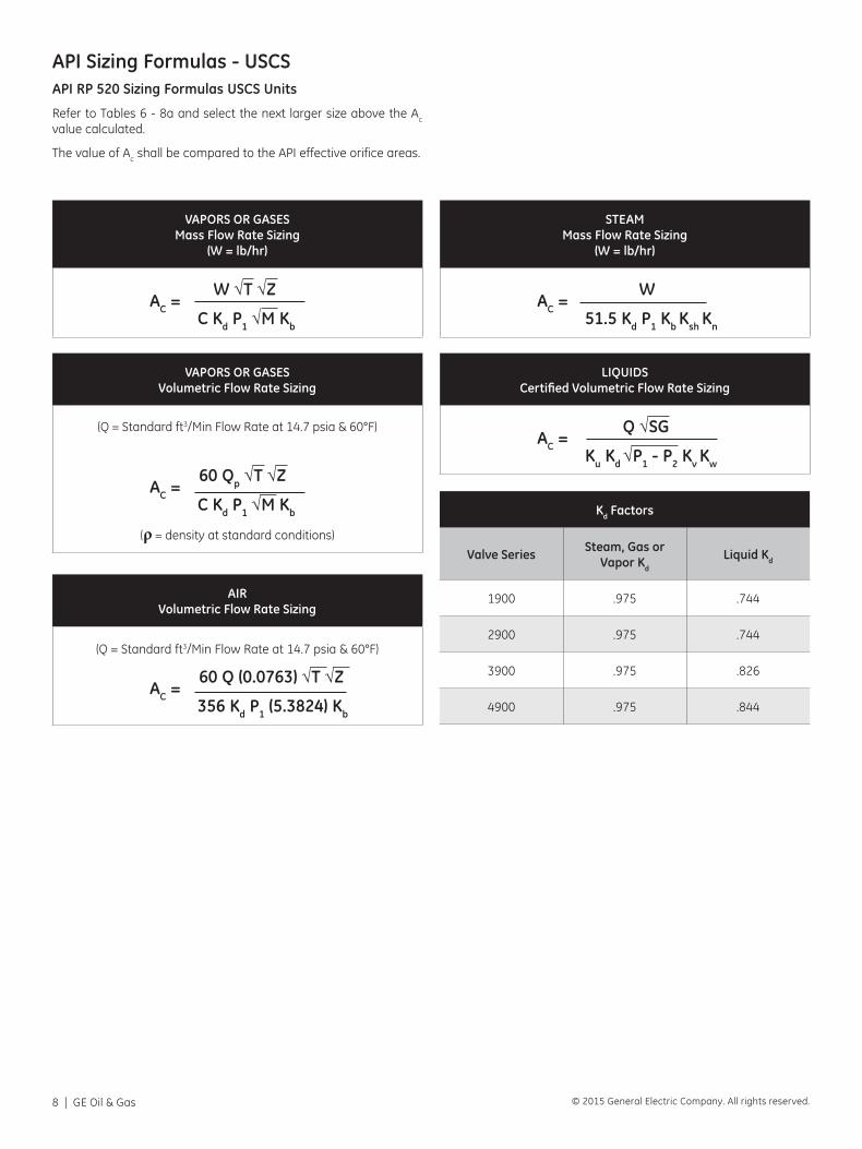
API Sizing Formulas - USCSAPI RP 520 Sizing Formulas USCS Units
Refer to Tables 6 - 8a and select the next larger size above the Ac
value calculated.
The value of Ac shall be compared to the API effective orifice areas.
VAPORS OR GASESMass Flow Rate Sizing
(W = lb/hr)
AC = W √T √Z
C Kd P1 √M Kb
STEAMMass Flow Rate Sizing
(W = lb/hr)
AC = W
51.5 Kd P1 Kb Ksh Kn
VAPORS OR GASESVolumetric Flow Rate Sizing
(Q = Standard ft3/Min Flow Rate at 14.7 psia & 60°F)
AC = 60 Qp √T √Z
C Kd P1 √M Kb
(ρ = density at standard conditions)
LIQUIDSCertified Volumetric Flow Rate Sizing
AC = Q √SG
Ku Kd √P1 - P2 Kv Kw
AIRVolumetric Flow Rate Sizing
(Q = Standard ft3/Min Flow Rate at 14.7 psia & 60°F)
AC = 60 Q (0.0763) √T √Z
356 Kd P1 (5.3824) Kb
Kd Factors
Valve Series Steam, Gas or Vapor Kd
Liquid Kd
1900 .975 .744
2900 .975 .744
3900 .975 .826
4900 .975 .844
Consolidated Valves Sizing and Selection | 9© 2015 General Electric Company. All rights reserved.
VAPORS OR GASESMass Flow Rate Sizing
(W = kg/hr)
AC = W √T √Z
C K P1 √M Kb
STEAMMass Flow Rate Sizing
(W = kg/hr)
AC = W
51.5 K P1 Kb Ksh Kn
VAPORS OR GASESVolumetric Flow Rate Sizing
(Q = Standard ft3 min flow rate at 14.7 psig and 60°F)
AC = 60 Qρ √T √Z
C K P1 √M Kb
(ρ = density at standard conditions)
LIQUIDSCertified Volumetric Flow Rate Sizing
(If Q = U.S. Gallons per minute, Ku = 38)(If Q = Cubic feet per hour, Ku = 5.2143)
AC = Q √SG
Ku K √P1 - P2 Kv Kw
AIRVolumetric Flow Rate Sizing
(Q = Standard ft3 min flow rate at 14.7 psig and 60°F)
AC = 60 Q (0.0763) √T √Z
356 K P1 (5.3824) Kb
K Factors (Kd x 0.9)
Valve Series Steam, Gas or Vapor K Liquid K
1900 .855 .670
1982 .855 .758
2900 .855 .670
3900 .878 .743
4900 .878 .760
13900 (all except 201 in2)
.877 N/A
13900 (201 in2 only) .850 N/A
19000 .878 .673
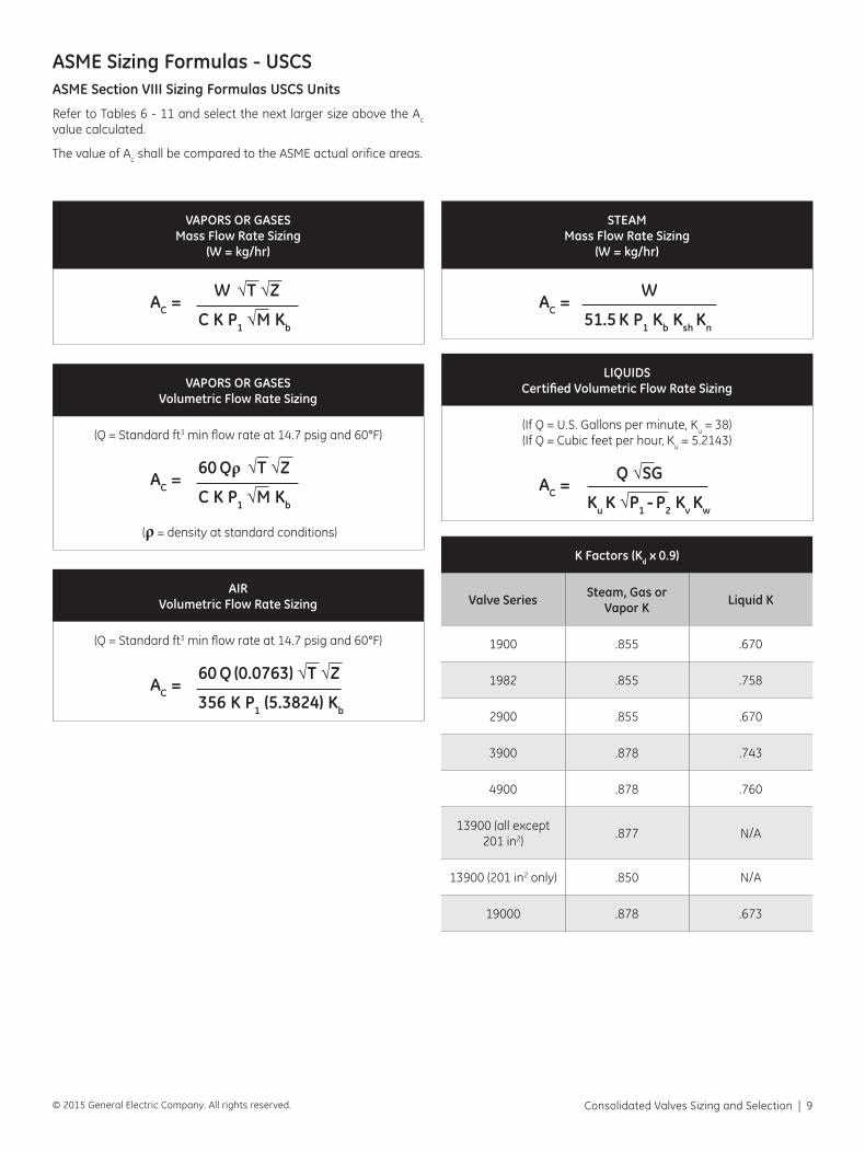
ASME Sizing Formulas - USCSASME Section VIII Sizing Formulas USCS Units
Refer to Tables 6 - 11 and select the next larger size above the Ac value calculated.
The value of Ac shall be compared to the ASME actual orifice areas.
10 | GE Oil & Gas © 2015 General Electric Company. All rights reserved.
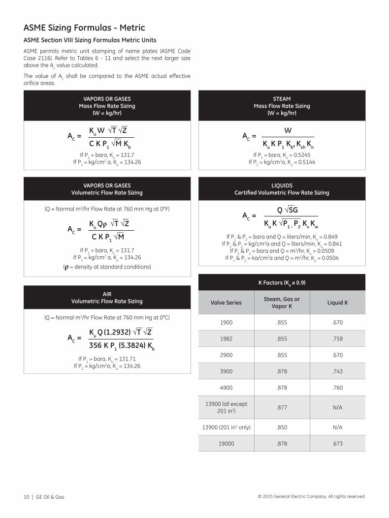
VAPORS OR GASESMass Flow Rate Sizing
(W = kg/hr)
AC = Ku W √T √Z
C K P1 √M Kb
If P1 = bara, Ku = 131.7If P1 = kg/cm2 a, Ku = 134.26
STEAMMass Flow Rate Sizing
(W = kg/hr)
AC = W
Ku K P1 Kb, Ksh Kn
If P1 = bara, Ku = 0.5245If P1 = kg/cm2a, Ku = 0.5144
VAPORS OR GASESVolumetric Flow Rate Sizing
(Q = Normal m3/hr Flow Rate at 760 mm Hg at 0°F)
AC = Ku Qρ √T √Z
C K P1 √M
If P1 = bara, Ku = 131.7If P1 = kg/cm2 a, Ku = 134.26
(ρ = density at standard conditions)
LIQUIDSCertified Volumetric Flow Rate Sizing
AC = Q √SG
Ku K √P1 - P2 Kv Kw
If P1 & P2 = bara and Q = liters/min, Ku = 0.849If P1 & P2 = kg/cm2a and Q = liters/min, Ku = 0.841
If P1 & P2 = bara and Q = m3/hr, Ku = 0.0509If P1 & P2 = ka/cm2a and Q = m3/hr, Ku = 0.0504
AIRVolumetric Flow Rate Sizing
(Q = Normal m3/hr Flow Rate at 760 mm Hg at 0°C)
AC = Ku Q (1.2932) √T √Z
356 K P1 (5.3824) Kb
If P1 = bara, Ku = 131.71If P1 = kg/cm2a, Ku = 134.26
K Factors (Kd x 0.9)
Valve Series Steam, Gas or Vapor K Liquid K
1900 .855 .670
1982 .855 .758
2900 .855 .670
3900 .878 .743
4900 .878 .760
13900 (all except 201 in2)
.877 N/A
13900 (201 in2 only) .850 N/A
19000 .878 .673
ASME Sizing Formulas - MetricASME Section VIII Sizing Formulas Metric Units
ASME permits metric unit stamping of name plates (ASME Code Case 2116). Refer to Tables 6 - 11 and select the next larger size above the Ac value calculated.
The value of Ac shall be compared to the ASME actual effective orifice areas.
Consolidated Valves Sizing and Selection | 11© 2015 General Electric Company. All rights reserved.
Correction Factors
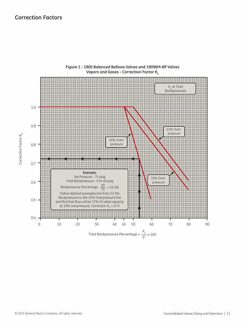
Figure 1 - 1900 Balanced Bellows Valves and 19096M-BP ValvesVapors and Gases - Correction Factor Kb
0
0.4
0.5
0.6
0.7
0.8
0.9
1.0
10 20 30 40 45 50 60 70 80 90
Total Backpressure Percentage = Pb x 100
P
Cor
rect
ion
Fact
or K
b
Example:Set Pressure - 75 psig
Total Backpressure - 0 to 40 psig
Backpressure Percentage 40 = 53.3% 75
Follow dashed examples line from 53.3%Backpressure to the 10% Overpressure line
and find that flow will be 72% of rated capacity at 10% overpressure. Correction Kb = 0.72
10% Over-pressure
21% Over-pressure
16% Over-pressure
Kb at Total Backpressures
12 | GE Oil & Gas © 2015 General Electric Company. All rights reserved.
0
0
0.0
0.0
0.1
0.1
0.2
0.2
0.3
0.3
0.4
0.4
0.5
0.5
0.6
0.6
0.7
0.7
0.8
0.8
0.9
0.9
1.0
1.0
10
10
20
20
30
30
40
40
50
50
60
60
70
70
80
80
90
90
100
Total Backpressure Percentage = P2 x 100
P1
Total Backpressure Percentage = Pb x 100
P
Cor
rect
ion
Fact
or K
b
Cor
rect
ion
Fact
or K
w
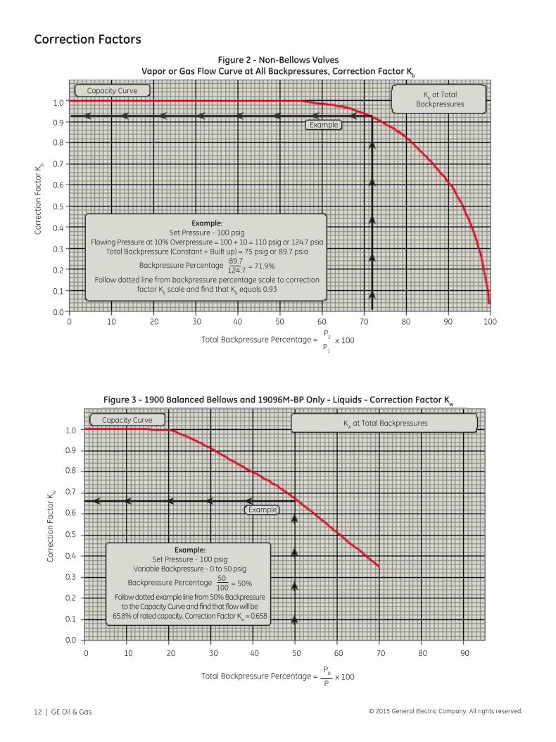
Correction FactorsFigure 2 - Non-Bellows Valves
Vapor or Gas Flow Curve at All Backpressures, Correction Factor Kb
Figure 3 - 1900 Balanced Bellows and 19096M-BP Only - Liquids - Correction Factor Kw
Kb at Total Backpressures
Kw at Total Backpressures
Capacity Curve
Capacity Curve
Example:Set Pressure - 100 psig
Flowing Pressure at 10% Overpressure = 100 + 10 = 110 psig or 124.7 psiaTotal Backpressure (Constant + Built up) = 75 psig or 89.7 psia
Backpressure Percentage 89.7 = 71.9% 124.7
Follow dotted line from backpressure percentage scale to correction factor Kb scale and find that Kb equals 0.93
Example:Set Pressure - 100 psig
Variable Backpressure - 0 to 50 psig
Backpressure Percentage 50 = 50% 100
Follow dotted example line from 50% Backpressure to the Capacity Curve and find that flow will be
65.8% of rated capacity. Correction Factor Kw = 0.658
Example
Example
Consolidated Valves Sizing and Selection | 13© 2015 General Electric Company. All rights reserved.
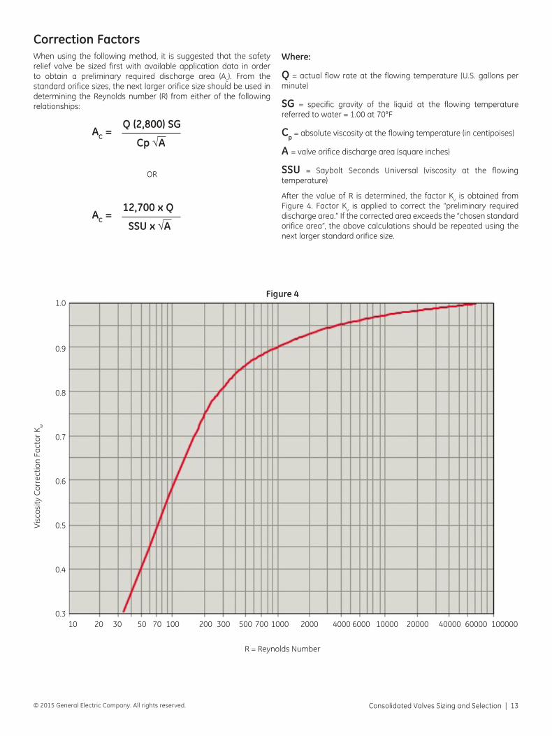
Correction FactorsWhen using the following method, it is suggested that the safety relief valve be sized first with available application data in order to obtain a preliminary required discharge area (Ac). From the standard orifice sizes, the next larger orifice size should be used in determining the Reynolds number (R) from either of the following relationships:
AC = Q (2,800) SG
Cp √A
OR
AC =
12,700 x Q
SSU x √A
Where:
Q = actual flow rate at the flowing temperature (U.S. gallons per minute)
SG = specific gravity of the liquid at the flowing temperature referred to water = 1.00 at 70°F
Cp = absolute viscosity at the flowing temperature (in centipoises)
A = valve orifice discharge area (square inches)
SSU = Saybolt Seconds Universal (viscosity at the flowing temperature)
After the value of R is determined, the factor Kv is obtained from Figure 4. Factor Kv is applied to correct the “preliminary required discharge area.” If the corrected area exceeds the “chosen standard orifice area”, the above calculations should be repeated using the next larger standard orifice size.
100.3
0.4
0.5
0.6
0.7
0.8
0.9
1.0
20 30 50 100 200 300 500 700 1000 2000 4000 6000 10000 20000 40000 60000 10000070
R = Reynolds Number
Visc
osity
Cor
rect
ion
Fact
or K
w
Figure 4
14 | GE Oil & Gas © 2015 General Electric Company. All rights reserved.
Fluid Properties
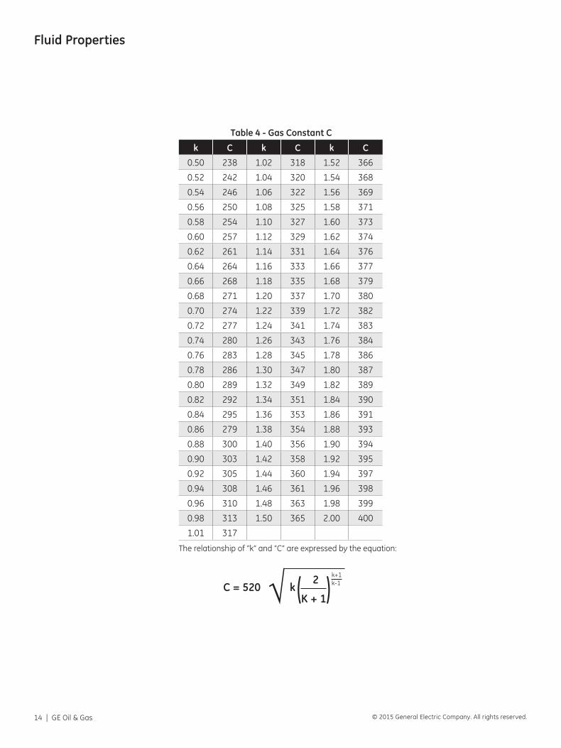
Table 4 - Gas Constant C
k C k C k C
0.50 238 1.02 318 1.52 366
0.52 242 1.04 320 1.54 368
0.54 246 1.06 322 1.56 369
0.56 250 1.08 325 1.58 371
0.58 254 1.10 327 1.60 373
0.60 257 1.12 329 1.62 374
0.62 261 1.14 331 1.64 376
0.64 264 1.16 333 1.66 377
0.66 268 1.18 335 1.68 379
0.68 271 1.20 337 1.70 380
0.70 274 1.22 339 1.72 382
0.72 277 1.24 341 1.74 383
0.74 280 1.26 343 1.76 384
0.76 283 1.28 345 1.78 386
0.78 286 1.30 347 1.80 387
0.80 289 1.32 349 1.82 389
0.82 292 1.34 351 1.84 390
0.84 295 1.36 353 1.86 391
0.86 279 1.38 354 1.88 393
0.88 300 1.40 356 1.90 394
0.90 303 1.42 358 1.92 395
0.92 305 1.44 360 1.94 397
0.94 308 1.46 361 1.96 398
0.96 310 1.48 363 1.98 399
0.98 313 1.50 365 2.00 400
1.01 317
The relationship of “k” and “C” are expressed by the equation:
C = 520
k 2
K + 1
k+1k-1( )√
Consolidated Valves Sizing and Selection | 15© 2015 General Electric Company. All rights reserved.
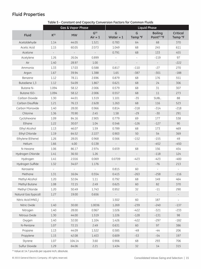
Fluid Properties
Table 5 - Constant and Capacity Conversion Factors for Common Fluids
Gas & Vapor Phase Liquid Phase
Fluid K(1) MW G(1) Air = 1
GWater = 1
GTemp °F
Boiling Point(1) °F
CriticalTemp °F
Acetaldehyde 1.14 44.05 1.521 0.783 64 68 370
Acetic Acid 1.15 60.05 2.073 1.049 68 245 611
Acetone - - - 0.791 68 133 455
Acetylene 1.26 26.04 0.899 - - -119 97
Air 1.40 28.97 1.00 - - - -222
Ammonia 1.33 17.03 0.588 0.817 -110 -27 270
Argon 1.67 39.94 1.388 1.65 -387 -301 -188
Benzene 1.12 78.11 2.696 0.879 68 176 551
Butadiene 1,3 1.12 54.09 1.867 0.621 68 24 306
Butane N- 1.094 58.12 2.006 0.579 68 31 307
Butane ISO- 1.094 58.12 2.006 0.557 68 11 273
Carbon Dioxide 1.30 44.01 1.519 1.101 -35 SUBL. 88
Carbon Disulfide 1.21 76.13 2.628 1.263 68 116 523
Carbon Monoxide 1.40 28.00 0.966 0.814 -318 -314 -218
Chlorine 1.36 70.90 2.45 1.58 -29 -30 291
Cyclohexane 1.09 84.16 2.905 0.779 69 177 538
Ethane 1.22 30.07 1.04 0.546 -126 -127 90
Ethyl Alcohol 1.13 46.07 1.59 0.789 68 173 469
Ethyl Chloride 1.19 64.52 2.227 0.903 50 54 369
Ethylene (Ethene) 1.26 28.05 0.968 0.566 -152 -155 49
Helium 1.66 4.00 0.138 - - -452 -450
N-Hexane 1.06 86.17 2.974 0.659 68 156 454
Hydrogen Chloride 1.41 36.50 1.26 - - -118 124
Hydrogen 1.41 2.016 0.069 0.0709 -423 -423 -400
Hydrogen Sulfide 1.32 34.07 1.176 - - -76 213
Kerosene - - - 0.815 60 - -
Methane 1.31 16.04 0.554 0.415 -263 -258 -116
Methyl Alcohol 1.20 32.04 1.11 0.792 68 149 464
Methyl Butane 1.08 72.15 2.49 0.625 60 82 370
Methyl Chloride 1.20 50.49 1.743 0.952 32 -11 290
Natural Gas (typical) 1.27 19.00 0.656 - - - -
Nitric Acid (HNO3) - - - 1.502 60 187 -Nitric Oxide 1.40 30.00 1.0036 1.269 -239 -240 -137
Nitrogen 1.40 28.00 0.967 1.026 -422 -321 -233
Nitrous Oxide 1.30 44.00 1.519 1.226 -128 -131 98
Oxygen 1.40 32.00 1.104 1.426 -422 -297 -182
N-Pentane 1.07 72.15 2.49 0.631 60 97 386
Propane 1.13 44.09 1.522 0.585 -49 -44 206
Propylene 1.15 42.08 1.453 0.609 -53 -54 197
Styrene 1.07 104.14 3.60 0.906 68 293 706
Sulfur Dioxide 1.29 64.06 2.21 1.434 32 14 315(1) Value at 14.7 pounds per square inch, absolute.
16 | GE Oil & Gas © 2015 General Electric Company. All rights reserved.
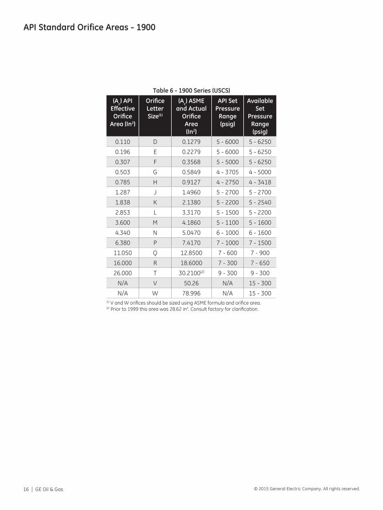
API Standard Orifice Areas - 1900
Table 6 - 1900 Series (USCS)
(Ac) API Effective Orifice
Area (In2)
OrificeLetterSize(1)
(Ac) ASMEand Actual
OrificeArea(In2)
API SetPressure
Range(psig)
AvailableSet
PressureRange(psig)
0.110 D 0.1279 5 - 6000 5 - 6250
0.196 E 0.2279 5 - 6000 5 - 6250
0.307 F 0.3568 5 - 5000 5 - 6250
0.503 G 0.5849 4 - 3705 4 - 5000
0.785 H 0.9127 4 - 2750 4 - 3418
1.287 J 1.4960 5 - 2700 5 - 2700
1.838 K 2.1380 5 - 2200 5 - 2540
2.853 L 3.3170 5 - 1500 5 - 2200
3.600 M 4.1860 5 - 1100 5 - 1600
4.340 N 5.0470 6 - 1000 6 - 1600
6.380 P 7.4170 7 - 1000 7 - 1500
11.050 Q 12.8500 7 - 600 7 - 900
16.000 R 18.6000 7 - 300 7 - 650
26.000 T 30.2100(2) 9 - 300 9 - 300
N/A V 50.26 N/A 15 - 300
N/A W 78.996 N/A 15 - 300(1) V and W orifices should be sized using ASME formula and orifice area. (2) Prior to 1999 this area was 28.62 in2. Consult factory for clarification.
Consolidated Valves Sizing and Selection | 17© 2015 General Electric Company. All rights reserved.
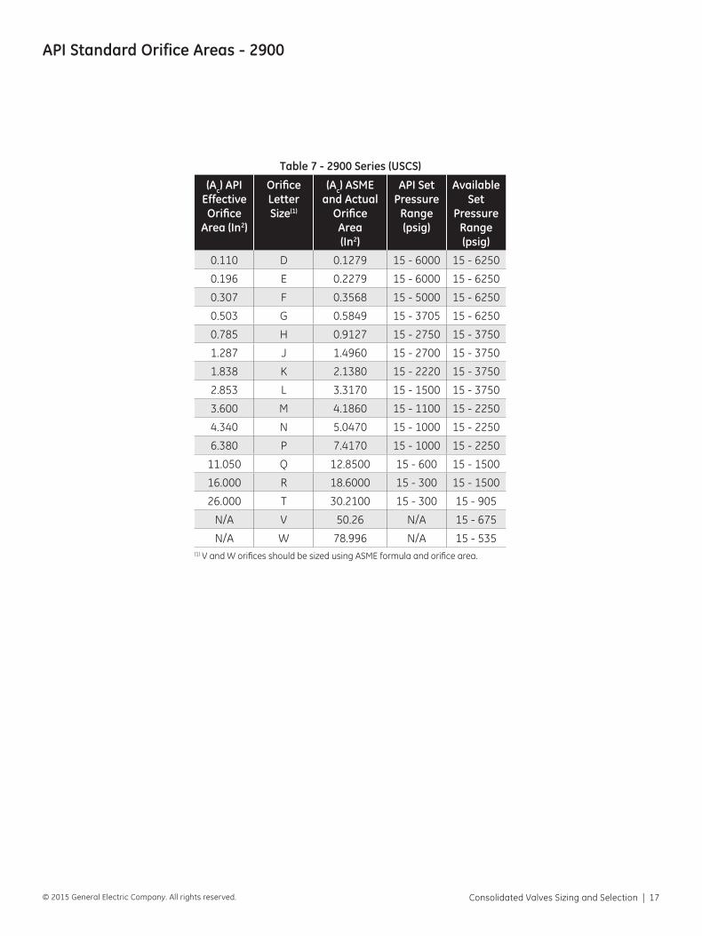
API Standard Orifice Areas - 2900
Table 7 - 2900 Series (USCS)
(Ac) API Effective Orifice
Area (In2)
OrificeLetterSize(1)
(Ac) ASMEand Actual
OrificeArea(In2)
API SetPressure
Range(psig)
AvailableSet
PressureRange(psig)
0.110 D 0.1279 15 - 6000 15 - 6250
0.196 E 0.2279 15 - 6000 15 - 6250
0.307 F 0.3568 15 - 5000 15 - 6250
0.503 G 0.5849 15 - 3705 15 - 6250
0.785 H 0.9127 15 - 2750 15 - 3750
1.287 J 1.4960 15 - 2700 15 - 3750
1.838 K 2.1380 15 - 2220 15 - 3750
2.853 L 3.3170 15 - 1500 15 - 3750
3.600 M 4.1860 15 - 1100 15 - 2250
4.340 N 5.0470 15 - 1000 15 - 2250
6.380 P 7.4170 15 - 1000 15 - 2250
11.050 Q 12.8500 15 - 600 15 - 1500
16.000 R 18.6000 15 - 300 15 - 1500
26.000 T 30.2100 15 - 300 15 - 905
N/A V 50.26 N/A 15 - 675
N/A W 78.996 N/A 15 - 535(1) V and W orifices should be sized using ASME formula and orifice area.
18 | GE Oil & Gas © 2015 General Electric Company. All rights reserved.
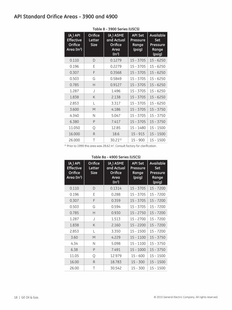
Table 8 - 3900 Series (USCS)
(Ac) API Effective Orifice
Area (In2)
OrificeLetter
Size
(Ac) ASMEand Actual
OrificeArea(In2)
API SetPressure
Range(psig)
AvailableSet
PressureRange(psig)
0.110 D 0.1279 15 - 3705 15 - 6250
0.196 E 0.2279 15 - 3705 15 - 6250
0.307 F 0.3568 15 - 3705 15 - 6250
0.503 G 0.5849 15 - 3705 15 - 6250
0.785 H 0.9127 15 - 3705 15 - 6250
1.287 J 1.496 15 - 3705 15 - 6250
1.838 K 2.138 15 - 3705 15 - 6250
2.853 L 3.317 15 - 3705 15 - 6250
3.600 M 4.186 15 - 3705 15 - 3750
4.340 N 5.047 15 - 3705 15 - 3750
6.380 P 7.417 15 - 3705 15 - 3750
11.050 Q 12.85 15 - 1480 15 - 1500
16.000 R 18.6 15 - 915 15 - 1500
26.000 T 30.21(1) 15 - 900 15 - 1500(1) Prior to 1999 this area was 28.62 in2. Consult factory for clarification.
Table 8a - 4900 Series (USCS)
(Ac) API Effective Orifice
Area (In2)
OrificeLetter
Size
(Ac) ASMEand Actual
OrificeArea(In2)
API SetPressure
Range(psig)
AvailableSet
PressureRange(psig)
0.110 D 0.1314 15 - 3705 15 - 7200
0.196 E 0.288 15 - 3705 15 - 7200
0.307 F 0.359 15 - 3705 15 - 7200
0.503 G 0.594 15 - 3705 15 - 7200
0.785 H 0.930 15 - 2750 15 - 7200
1.287 J 1.513 15 - 2700 15 - 7200
1.838 K 2.160 15 - 2200 15 - 7200
2.853 L 3.350 15 - 1500 15 - 7200
3.60 M 4.229 15 - 1100 15 - 3750
4.34 N 5.098 15 - 1100 15 - 3750
6.38 P 7.491 15 - 1000 15 - 3750
11.05 Q 12.979 15 - 600 15 - 1500
16.00 R 18.783 15 - 300 15 - 1500
26.00 T 30.542 15 - 300 15 - 1500
API Standard Orifice Areas - 3900 and 4900
Consolidated Valves Sizing and Selection | 19© 2015 General Electric Company. All rights reserved.
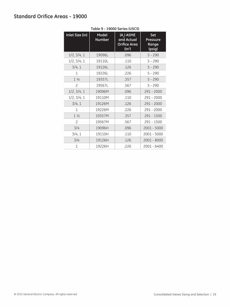
Table 9 - 19000 Series (USCS)
Inlet Size (in) Model Number
(Ac) ASMEand ActualOrifice Area
(In2)
SetPressure
Range(psig)
1/2, 3/4, 1 19096L .096 5 - 290
1/2, 3/4, 1 19110L .110 5 - 290
3/4, 1 19126L .126 5 - 290
1 19226L .226 5 - 290
1 ½ 19357L .357 5 - 290
2 19567L .567 5 - 290
1/2, 3/4, 1 19096M .096 291 - 2000
1/2, 3/4, 1 19110M .110 291 - 2000
3/4, 1 19126M .126 291 - 2000
1 19226M .226 291 - 2000
1 ½ 19357M .357 291 - 1500
2 19567M .567 291 - 1500
3/4 19096H .096 2001 - 5000
3/4, 1 19110H .110 2001 - 5000
3/4 19126H .126 2001 - 8000
1 19226H .226 2001 - 6400
Standard Orifice Areas - 19000
20 | GE Oil & Gas © 2015 General Electric Company. All rights reserved.
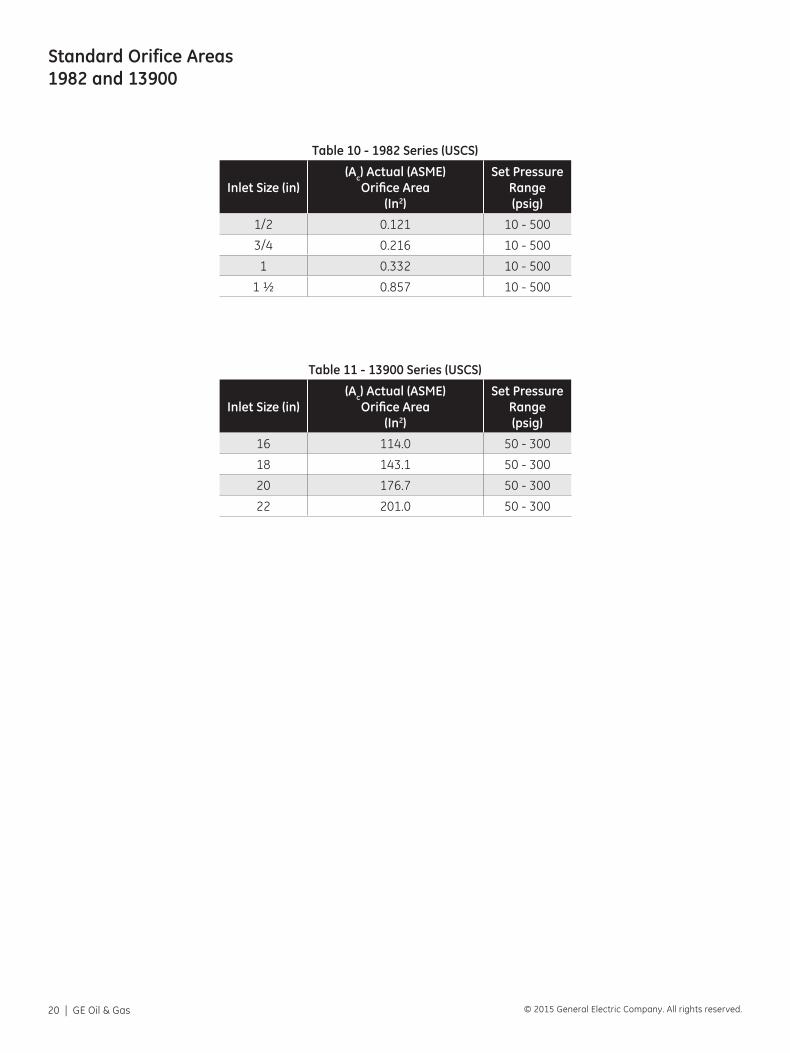
Table 10 - 1982 Series (USCS)
Inlet Size (in)(Ac) Actual (ASME)
Orifice Area(In2)
Set PressureRange(psig)
1/2 0.121 10 - 500
3/4 0.216 10 - 500
1 0.332 10 - 500
1 ½ 0.857 10 - 500
Table 11 - 13900 Series (USCS)
Inlet Size (in)(Ac) Actual (ASME)
Orifice Area(In2)
Set PressureRange(psig)
16 114.0 50 - 300
18 143.1 50 - 300
20 176.7 50 - 300
22 201.0 50 - 300
Standard Orifice Areas 1982 and 13900
Consolidated Valves Sizing and Selection | 21© 2015 General Electric Company. All rights reserved.
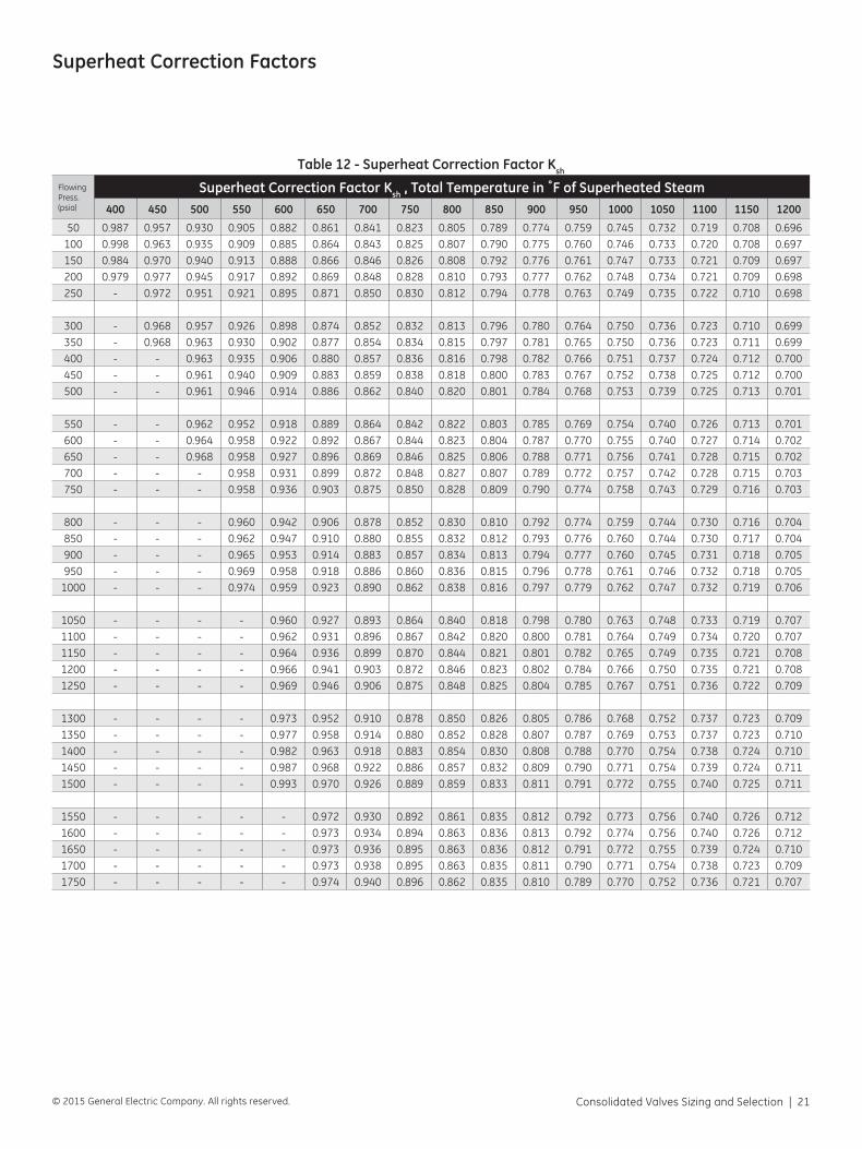
Superheat Correction Factors
Table 12 - Superheat Correction Factor Ksh
Flowing Press. (psia)
Superheat Correction Factor Ksh , Total Temperature in ˚F of Superheated Steam400 450 500 550 600 650 700 750 800 850 900 950 1000 1050 1100 1150 1200
50 0.987 0.957 0.930 0.905 0.882 0.861 0.841 0.823 0.805 0.789 0.774 0.759 0.745 0.732 0.719 0.708 0.696100 0.998 0.963 0.935 0.909 0.885 0.864 0.843 0.825 0.807 0.790 0.775 0.760 0.746 0.733 0.720 0.708 0.697150 0.984 0.970 0.940 0.913 0.888 0.866 0.846 0.826 0.808 0.792 0.776 0.761 0.747 0.733 0.721 0.709 0.697200 0.979 0.977 0.945 0.917 0.892 0.869 0.848 0.828 0.810 0.793 0.777 0.762 0.748 0.734 0.721 0.709 0.698250 - 0.972 0.951 0.921 0.895 0.871 0.850 0.830 0.812 0.794 0.778 0.763 0.749 0.735 0.722 0.710 0.698
300 - 0.968 0.957 0.926 0.898 0.874 0.852 0.832 0.813 0.796 0.780 0.764 0.750 0.736 0.723 0.710 0.699350 - 0.968 0.963 0.930 0.902 0.877 0.854 0.834 0.815 0.797 0.781 0.765 0.750 0.736 0.723 0.711 0.699400 - - 0.963 0.935 0.906 0.880 0.857 0.836 0.816 0.798 0.782 0.766 0.751 0.737 0.724 0.712 0.700450 - - 0.961 0.940 0.909 0.883 0.859 0.838 0.818 0.800 0.783 0.767 0.752 0.738 0.725 0.712 0.700500 - - 0.961 0.946 0.914 0.886 0.862 0.840 0.820 0.801 0.784 0.768 0.753 0.739 0.725 0.713 0.701
550 - - 0.962 0.952 0.918 0.889 0.864 0.842 0.822 0.803 0.785 0.769 0.754 0.740 0.726 0.713 0.701600 - - 0.964 0.958 0.922 0.892 0.867 0.844 0.823 0.804 0.787 0.770 0.755 0.740 0.727 0.714 0.702650 - - 0.968 0.958 0.927 0.896 0.869 0.846 0.825 0.806 0.788 0.771 0.756 0.741 0.728 0.715 0.702700 - - - 0.958 0.931 0.899 0.872 0.848 0.827 0.807 0.789 0.772 0.757 0.742 0.728 0.715 0.703750 - - - 0.958 0.936 0.903 0.875 0.850 0.828 0.809 0.790 0.774 0.758 0.743 0.729 0.716 0.703
800 - - - 0.960 0.942 0.906 0.878 0.852 0.830 0.810 0.792 0.774 0.759 0.744 0.730 0.716 0.704850 - - - 0.962 0.947 0.910 0.880 0.855 0.832 0.812 0.793 0.776 0.760 0.744 0.730 0.717 0.704900 - - - 0.965 0.953 0.914 0.883 0.857 0.834 0.813 0.794 0.777 0.760 0.745 0.731 0.718 0.705950 - - - 0.969 0.958 0.918 0.886 0.860 0.836 0.815 0.796 0.778 0.761 0.746 0.732 0.718 0.705
1000 - - - 0.974 0.959 0.923 0.890 0.862 0.838 0.816 0.797 0.779 0.762 0.747 0.732 0.719 0.706
1050 - - - - 0.960 0.927 0.893 0.864 0.840 0.818 0.798 0.780 0.763 0.748 0.733 0.719 0.7071100 - - - - 0.962 0.931 0.896 0.867 0.842 0.820 0.800 0.781 0.764 0.749 0.734 0.720 0.7071150 - - - - 0.964 0.936 0.899 0.870 0.844 0.821 0.801 0.782 0.765 0.749 0.735 0.721 0.7081200 - - - - 0.966 0.941 0.903 0.872 0.846 0.823 0.802 0.784 0.766 0.750 0.735 0.721 0.7081250 - - - - 0.969 0.946 0.906 0.875 0.848 0.825 0.804 0.785 0.767 0.751 0.736 0.722 0.709
1300 - - - - 0.973 0.952 0.910 0.878 0.850 0.826 0.805 0.786 0.768 0.752 0.737 0.723 0.7091350 - - - - 0.977 0.958 0.914 0.880 0.852 0.828 0.807 0.787 0.769 0.753 0.737 0.723 0.7101400 - - - - 0.982 0.963 0.918 0.883 0.854 0.830 0.808 0.788 0.770 0.754 0.738 0.724 0.7101450 - - - - 0.987 0.968 0.922 0.886 0.857 0.832 0.809 0.790 0.771 0.754 0.739 0.724 0.7111500 - - - - 0.993 0.970 0.926 0.889 0.859 0.833 0.811 0.791 0.772 0.755 0.740 0.725 0.711
1550 - - - - - 0.972 0.930 0.892 0.861 0.835 0.812 0.792 0.773 0.756 0.740 0.726 0.7121600 - - - - - 0.973 0.934 0.894 0.863 0.836 0.813 0.792 0.774 0.756 0.740 0.726 0.7121650 - - - - - 0.973 0.936 0.895 0.863 0.836 0.812 0.791 0.772 0.755 0.739 0.724 0.7101700 - - - - - 0.973 0.938 0.895 0.863 0.835 0.811 0.790 0.771 0.754 0.738 0.723 0.7091750 - - - - - 0.974 0.940 0.896 0.862 0.835 0.810 0.789 0.770 0.752 0.736 0.721 0.707
22 | GE Oil & Gas © 2015 General Electric Company. All rights reserved.
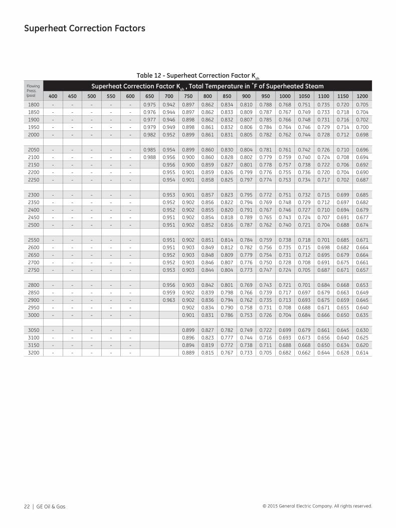
Table 12 - Superheat Correction Factor Ksh
Flowing Press. (psia)
Superheat Correction Factor Ksh , Total Temperature in ˚F of Superheated Steam400 450 500 550 600 650 700 750 800 850 900 950 1000 1050 1100 1150 1200
1800 - - - - - 0.975 0.942 0.897 0.862 0.834 0.810 0.788 0.768 0.751 0.735 0.720 0.7051850 - - - - - 0.976 0.944 0.897 0.862 0.833 0.809 0.787 0.767 0.749 0.733 0.718 0.7041900 - - - - - 0.977 0.946 0.898 0.862 0.832 0.807 0.785 0.766 0.748 0.731 0.716 0.7021950 - - - - - 0.979 0.949 0.898 0.861 0.832 0.806 0.784 0.764 0.746 0.729 0.714 0.7002000 - - - - - 0.982 0.952 0.899 0.861 0.831 0.805 0.782 0.762 0.744 0.728 0.712 0.698
2050 - - - - - 0.985 0.954 0.899 0.860 0.830 0.804 0.781 0.761 0.742 0.726 0.710 0.6962100 - - - - - 0.988 0.956 0.900 0.860 0.828 0.802 0.779 0.759 0.740 0.724 0.708 0.6942150 - - - - - 0.956 0.900 0.859 0.827 0.801 0.778 0.757 0.738 0.722 0.706 0.6922200 - - - - - 0.955 0.901 0.859 0.826 0.799 0.776 0.755 0.736 0.720 0.704 0.6902250 - - - - - 0.954 0.901 0.858 0.825 0.797 0.774 0.753 0.734 0.717 0.702 0.687
2300 - - - - - 0.953 0.901 0.857 0.823 0.795 0.772 0.751 0.732 0.715 0.699 0.6852350 - - - - - 0.952 0.902 0.856 0.822 0.794 0.769 0.748 0.729 0.712 0.697 0.6822400 - - - - - 0.952 0.902 0.855 0.820 0.791 0.767 0.746 0.727 0.710 0.694 0.6792450 - - - - - 0.951 0.902 0.854 0.818 0.789 0.765 0.743 0.724 0.707 0.691 0.6772500 - - - - - 0.951 0.902 0.852 0.816 0.787 0.762 0.740 0.721 0.704 0.688 0.674
2550 - - - - - 0.951 0.902 0.851 0.814 0.784 0.759 0.738 0.718 0.701 0.685 0.6712600 - - - - - 0.951 0.903 0.849 0.812 0.782 0.756 0.735 0.715 0.698 0.682 0.6642650 - - - - - 0.952 0.903 0.848 0.809 0.779 0.754 0.731 0.712 0.695 0.679 0.6642700 - - - - - 0.952 0.903 0.846 0.807 0.776 0.750 0.728 0.708 0.691 0.675 0.6612750 - - - - - 0.953 0.903 0.844 0.804 0.773 0.747 0.724 0.705 0.687 0.671 0.657
2800 - - - - - 0.956 0.903 0.842 0.801 0.769 0.743 0.721 0.701 0.684 0.668 0.6532850 - - - - - 0.959 0.902 0.839 0.798 0.766 0.739 0.717 0.697 0.679 0.663 0.6492900 - - - - - 0.963 0.902 0.836 0.794 0.762 0.735 0.713 0.693 0.675 0.659 0.6452950 - - - - - 0.902 0.834 0.790 0.758 0.731 0.708 0.688 0.671 0.655 0.6403000 - - - - - 0.901 0.831 0.786 0.753 0.726 0.704 0.684 0.666 0.650 0.635
3050 - - - - - 0.899 0.827 0.782 0.749 0.722 0.699 0.679 0.661 0.645 0.6303100 - - - - - 0.896 0.823 0.777 0.744 0.716 0.693 0.673 0.656 0.640 0.6253150 - - - - - 0.894 0.819 0.772 0.738 0.711 0.688 0.668 0.650 0.634 0.6203200 - - - - - 0.889 0.815 0.767 0.733 0.705 0.682 0.662 0.644 0.628 0.614
Superheat Correction Factors
Consolidated Valves Sizing and Selection | 23© 2015 General Electric Company. All rights reserved.
ASME Rupture Disk Combinations Kc
A) Rupture Disk not Certified with the Safety Relief Valve
For those situations, the safety relief valve is sized in accordance with previously identified methods. However, this combination of rupture disk and pressure relief valve can only be credited with 90% of its ASME certified relieving capacity.
B) Rupture Disk is certified with the Safety Relief Valve Kc
In this case, the particular type of safety relief valve has been actually flow tested in combination with a unique rupture disk supplier’s design type and a combination capacity factor established. The combination capacity factor is published by the National Board of Boiler & Pressure Vessels.
The safety relief valve ASME certified relieving capacity must be multiplied by the combination capacity factor to obtain the allowable ASME relieving capacity for the combination of the safety relief valve and rupture disk.
C) In all cases ASME installation requirements must be followed. Refer to ASME Code Section VIII, paragraph UG-127.
24 | GE Oil & Gas © 2015 General Electric Company. All rights reserved.
API Fire Sizing
API Fire Sizing
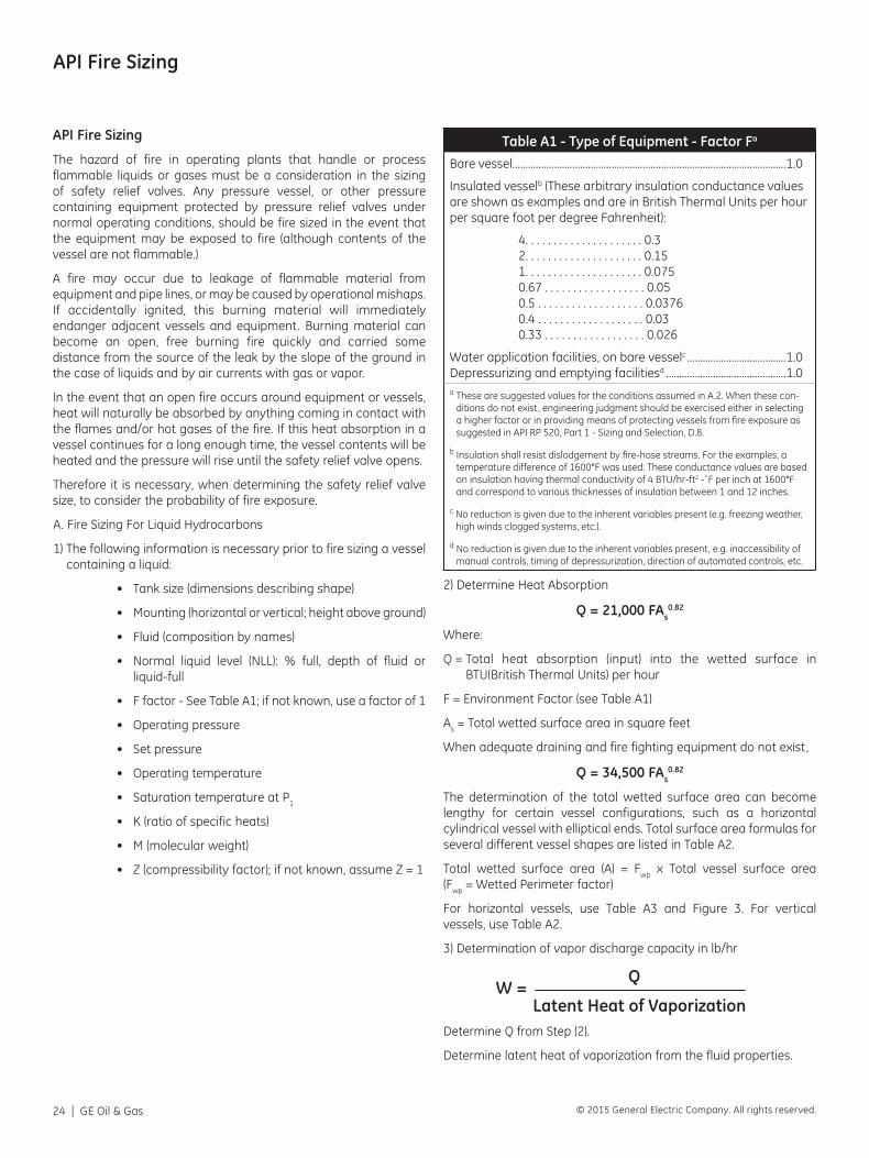
The hazard of fire in operating plants that handle or process flammable liquids or gases must be a consideration in the sizing of safety relief valves. Any pressure vessel, or other pressure containing equipment protected by pressure relief valves under normal operating conditions, should be fire sized in the event that the equipment may be exposed to fire (although contents of the vessel are not flammable.)
A fire may occur due to leakage of flammable material from equipment and pipe lines, or may be caused by operational mishaps. If accidentally ignited, this burning material will immediately endanger adjacent vessels and equipment. Burning material can become an open, free burning fire quickly and carried some distance from the source of the leak by the slope of the ground in the case of liquids and by air currents with gas or vapor.
In the event that an open fire occurs around equipment or vessels, heat will naturally be absorbed by anything coming in contact with the flames and/or hot gases of the fire. If this heat absorption in a vessel continues for a long enough time, the vessel contents will be heated and the pressure will rise until the safety relief valve opens.
Therefore it is necessary, when determining the safety relief valve size, to consider the probability of fire exposure.
A. Fire Sizing For Liquid Hydrocarbons
1) The following information is necessary prior to fire sizing a vessel containing a liquid:
• Tank size (dimensions describing shape)
• Mounting (horizontal or vertical; height above ground)
• Fluid (composition by names)
• Normal liquid level (NLL): % full, depth of fluid or liquid-full
• F factor - See Table A1; if not known, use a factor of 1
• Operating pressure
• Set pressure
• Operating temperature
• Saturation temperature at P1
• K (ratio of specific heats)
• M (molecular weight)
• Z (compressibility factor); if not known, assume Z = 1
Table A1 - Type of Equipment - Factor Fa
Bare vessel.........................................................................................................1.0
Insulated vesselb (These arbitrary insulation conductance values are shown as examples and are in British Thermal Units per hour per square foot per degree Fahrenheit):
4. . . . . . . . . . . . . . . . . . . . . 0.3 2. . . . . . . . . . . . . . . . . . . . . 0.15 1. . . . . . . . . . . . . . . . . . . . . 0.075 0.67 . . . . . . . . . . . . . . . . . . 0.05 0.5 . . . . . . . . . . . . . . . . . . . 0.0376 0.4 . . . . . . . . . . . . . . . . . . . 0.03 0.33 . . . . . . . . . . . . . . . . . . 0.026
Water application facilities, on bare vesselc ......................................1.0 Depressurizing and emptying facilitiesd ..............................................1.0a These are suggested values for the conditions assumed in A.2. When these con-
ditions do not exist, engineering judgment should be exercised either in selecting a higher factor or in providing means of protecting vessels from fire exposure as suggested in API RP 520, Part 1 - Sizing and Selection, D.8.
b Insulation shall resist dislodgement by fire-hose streams. For the examples, a temperature difference of 1600°F was used. These conductance values are based on insulation having thermal conductivity of 4 BTU/hr-ft2 -˚F per inch at 1600°F and correspond to various thicknesses of insulation between 1 and 12 inches.
c No reduction is given due to the inherent variables present (e.g. freezing weather, high winds clogged systems, etc.).
d No reduction is given due to the inherent variables present, e.g. inaccessibility of manual controls, timing of depressurization, direction of automated controls, etc.
2) Determine Heat Absorption
Q = 21,000 FAs0.82
Where:
Q = Total heat absorption (input) into the wetted surface in BTU(British Thermal Units) per hour
F = Environment Factor (see Table A1)
As = Total wetted surface area in square feet
When adequate draining and fire fighting equipment do not exist,
Q = 34,500 FAs0.82
The determination of the total wetted surface area can become lengthy for certain vessel configurations, such as a horizontal cylindrical vessel with elliptical ends. Total surface area formulas for several different vessel shapes are listed in Table A2.
Total wetted surface area (A) = Fwp x Total vessel surface area (Fwp = Wetted Perimeter factor)
For horizontal vessels, use Table A3 and Figure 3. For vertical vessels, use Table A2.
3) Determination of vapor discharge capacity in lb/hr
W =
Q
Latent Heat of VaporizationDetermine Q from Step (2).
Determine latent heat of vaporization from the fluid properties.
Consolidated Valves Sizing and Selection | 25© 2015 General Electric Company. All rights reserved.
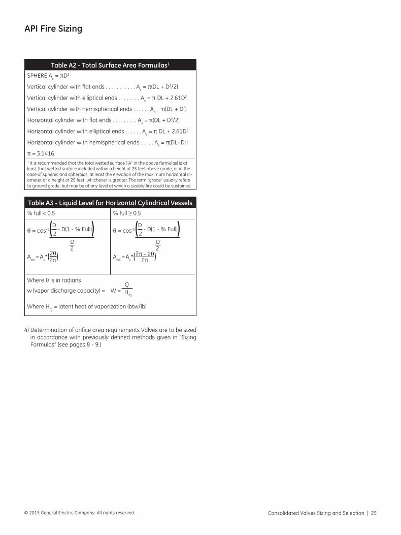
API Fire Sizing
Table A2 - Total Surface Area Formuilas1
SPHERE As = πD2
Vertical cylinder with flat ends . . . . . . . . . . . As = π(DL + D2/2)
Vertical cylinder with elliptical ends . . . . . . . . As = π DL + 2.61D2
Vertical cylinder with hemispherical ends . . . . . . As = π(DL + D2)
Horizontal cylinder with flat ends . . . . . . . . . As = π(DL + D2/2)
Horizontal cylinder with elliptical ends . . . . . . As = π DL + 2.61D2
Horizontal cylinder with hemispherical ends . . . . . As = π(DL+D2)
π = 3.14161 It is recommended that the total wetted surface (“A” in the above formulas) is at least that wetted surface included within a height of 25 feet above grade, or in the case of spheres and spheroids, at least the elevation of the maximum horizontal di-ameter or a height of 25 feet, whichever is greater. The term “grade” usually refers to ground grade, but may be at any level at which a sizable fire could be sustained.
Table A3 - Liquid Level for Horizontal Cylindrical Vessels% full < 0.5 % full ≥ 0.5
θ = cos-1 D
- D(1 - % Full)
2 D
2Aws = As*(2θ)
2π
θ = cos-1 D
- D(1 - % Full)
2 D
2Aws = As*(2π - 2θ)
2π
Where θ is in radians
w (vapor discharge capacity) = W = Q
Hfg
Where Hfg = latent heat of vaporization (btw/lb)
4) Determination of orifice area requirements Valves are to be sized in accordance with previously defined methods given in “Sizing Formulas” (see pages 8 - 9.)
( ) ( )
26 | GE Oil & Gas © 2015 General Electric Company. All rights reserved.
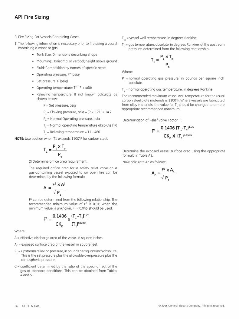
API Fire Sizing
B. Fire Sizing For Vessels Containing Gases
1) The following information is necessary prior to fire sizing a vessel containing a vapor or gas.
• Tank Size: Dimensions describing shape
• Mounting: Horizontal or vertical; height above ground
• Fluid: Composition by names of specific heats
• Operating pressure: P° (psia)
• Set pressure, P (psig)
• Operating temperature: T° (˚F + 460)
• Relieving temperature: If not known calculate as shown below:
P = Set pressure, psig
P1 = Flowing pressure, psia = (P x 1.21) + 14.7
Po = Normal Operating pressure, psia
To = Normal operating temperature absolute (˚R)
T1 = Relieving temperature = T1 - 460
NOTE: Use caution when T1 exceeds 1100°F for carbon steel.
T1 =
P1 x To
Po
2) Determine orifice area requirement.
The required orifice area for a safety relief valve on a gas-containing vessel exposed to an open fire can be determined by the following formula.
A =
F1 x A1
√ P1
F1 can be determined from the following relationship. The recommended minimum value of F1 is 0.01; when the minimum value is unknown, F1 = 0.045 should be used.
F1 = 0.1406
x (Tω-T1)
1.25
CKD (T1)0.6506
Where:
A = effective discharge area of the valve, in square inches.
A1 = exposed surface area of the vessel, in square feet.
P1 = upstream relieving pressure, in pounds per square inch absolute. This is the set pressure plus the allowable overpressure plus the atmospheric pressure.
C = coefficient determined by the ratio of the specific heat of the gas at standard conditions. This can be obtained from Tables 4 and 5.
Tω = vessel wall temperature, in degrees Rankine.
T1 = gas temperature, absolute, in degrees Rankine, at the upstream pressure, determined from the following relationship:
T1 =
P1 x Tn
Pn
Where:
Pη = normal operating gas pressure, in pounds per square inch absolute.
Tη = normal operating gas temperature, in degrees Rankine.
The recommended maximum vessel wall temperature for the usual carbon steel plate materials is 1100°F. Where vessels are fabricated from alloy materials, the value for Tω should be changed to a more appropriate recommended maximum.
Determination of Relief Valve Factor F1:
F1 =
0.1406 (Tω-T1)1.25
CKD X (T1)0.6506
Determine the exposed vessel surface area using the appropriate formula in Table A2.
Now calculate Ac as follows:
AC =
F1 x AS
√ P1

Consolidated Valves Sizing and Selection | 27© 2015 General Electric Company. All rights reserved.

GEA31796 04/2015
*Denotes a trademark of the General Electric Company. All other marks are the property of their respective owners.
© 2015 General Electric Company. All rights reserved.
www.geoilandgas.com/valves