Consolidated Facilities Planning Report Fishers Island ... · 10/5/2015 · Updated Draft: February...
43
Updated Draft: February 5, 2016 Consolidated Facilities Planning Report Fishers Island Waste Management District Prepared By: Project Management Associates, LLC PO Box 271777 • West Hartford, CT 06127 860.756.0302 • Fax 866.483.8588 With: Anchor Engineering Services, Inc. 41 Sequin Drive • Glastonbury, Connecticut 06033-2314 (860) 633-8770 • Fax (860) 633-5971
Transcript of Consolidated Facilities Planning Report Fishers Island ... · 10/5/2015 · Updated Draft: February...

Updated Draft: February 5, 2016
Consolidated Facilities Planning Report
Fishers Island Waste Management District
Prepared By:
Project Management Associates, LLC
PO Box 271777 • West Hartford, CT 06127 860.756.0302 • Fax 866.483.8588
With:
Anchor Engineering Services, Inc. 41 Sequin Drive • Glastonbury, Connecticut 06033-2314
(860) 633-8770 • Fax (860) 633-5971

PO Box 271777 West Hartford, CT 06127 (860) 756-0302 Fax (866) 483-8588
February 5, 2016 Board of Commissioners Fishers Island Waste Management District P.O. Box 22 Fishers Island, NY 06390 Subject: Updated Draft; Consolidated Facilities Planning Report Honorable Commissioners: Attached is our updated version of the planning, prepared at your request and authorization. This report incorporates:
- A summary discussion of daily operations at the proposed consolidated facility, as requested by NYSDEC;
- Our most recent thoughts on organics processing; and, - In recognition that the District has determined it will pursue consolidation of its services at the
current “compost” site; this version is focused upon that approach. We look forward to reviewing this with you in the near future and receiving your comments and suggestions. Thank you for this continuing opportunity to be of assistance to the District.
Very truly yours, David S. Brown, P.E. President, PMA LLC

Draft: February5, 2016 Consolidated Facilities Planning Report
Fishers Island Waste Management District
i
Facilities Planning Report
Fishers Island Waste Management District
Contents
Purpose of Report ..................................................................................................................................................................... 1 Background .............................................................................................................................................................................. 1 Consideration of Alternatives ................................................................................................................................................... 2 Summary and Conclusions ....................................................................................................................................................... 2 Limitations & Concerns Regarding Current Facilities ............................................................................................................. 3 Opportunities To Reduce Waste & Increase Compost Production ........................................................................................... 4 Improvements Considered & Conceptual Plans ....................................................................................................................... 6
Concept Plans – Combined Operations ............................................................................................................................ 7 Preliminary Cost Estimate ........................................................................................................................................................ 8
Est. Capital Cost; Improvements At the Compost Station.................................................................................................... 9 Table 1; Preliminary Estimate of Costs for Option A-Combined Operations at Compost Station ................................. 10
Benefits of Consolidated Operations ...................................................................................................................................... 11 How The Consolidated Facility Would Operate .................................................................................................................... 11
Municipal Solid Waste (“MSW”)................................................................................................................................... 11 Mixed Recyclables (Single-Stream) ............................................................................................................................... 11 Source Separated Food Waste & Other Recyclable Organics ........................................................................................ 12 Bulky, Oversized Wastes ............................................................................................................................................... 13 Construction and Demolition Wood Waste .................................................................................................................... 13 Re-Use of Discarded Items ............................................................................................................................................. 13
Appendices: A: Sustainable Generation Company Quote of July 17, 2015 (Composting Technology) B: Site Improvement Concept Plans, Combined Operations at the Compost Site C: Concept Plan, Improvements to Existing Building

Draft: February5, 2016 Consolidated Facilities Planning Report
Fishers Island Waste Management District
1
Purpose of Report This report has been prepared at the request of the Fishers Island Waste Management District (“District”) to assist in meeting the following goals:
1. The District desires to modernize its facilities and methods for how wastes and recyclables will be handled in the future and, where appropriate, processed on the Island. Its goal is to maximize the on-Island management of materials and thereby, to the extent possible, reduce reliance upon the Ferry District and corresponding hauling costs for off-Island transportation of waste and recyclables;
2. The District has determined that the most cost-effective means to provide future services is through consolidation of the services it provides to the Island at the property it now owns and which is generally referred to as “the compost site”. Accordingly, this report also contains:
a. A concept level plan that shows how upgraded and new structures and activities can be implemented at the property; and,
b. An estimate of the capital costs of the improvements that would contribute to meeting the goals.
This effort is the result of a collaborative effort by representatives of the District, Project Management Associates, LLC (“PMA”), and Anchor Engineering Services, Inc. (“Anchor”).
Background Prior to 1990, landfilling was the key method of managing wastes generated on the Island. A primary landfill, now closed, accepted a range of household and commercial waste while another site was used to accumulate appliances and other scrap metals. The so-called “metals dump” on Town property has since been cleaned up. The site owned by the District and currently referred to as the compost station historically featured open-burning of brush and debris. After rejecting a plan to construct incinerators and an ash landfill on the Island to manage combustible wastes from residents and businesses, the District constructed a transfer station in 1991 on property owned by the Town of Southold. Now approaching 25 years in age, the transfer station continues to accept household and business wastes and recyclables. The District’s other operation is generally referred to as the compost station; however that site currently provides several functions:
1. It includes a structure which houses the District’s modest offices and a small maintenance garage;
2. Brush, logs and yard waste are received, processed and composted; 3. The District uses concrete structures built scores of years ago by the U.S. military as
coastal defense facilities. The structures include walls that create a grade separation that is used to receive deliveries of bulky waste materials (construction debris, furniture, mattresses, etc.), electronic wastes, and scrap metals at the upper level by residents, with open roll-off containers at the lower level to receive waste materials, and,
4. It has a small unprotected area where, on an informal basis, residents can place useable items for reuse by others.

Draft: February5, 2016 Consolidated Facilities Planning Report
Fishers Island Waste Management District
2
While the District has attempted to steadily adjust its operations to meet the needs of the Island, factors both on-Island and in the waste management industry at large have now combined to support the need for improvements to the District’s operations and facilities. For reasons unclear at this time, a decision was made some 25 years ago to construct the transfer station as a separate operation from the compost site (then referred to as the “burn dump”.) As a result, the District has continued to operate two separate locations, dividing its staff and the opening times for each. In part, there may have always been two separate operations going back historically to the time when the District operated a landfill and the compost site was used to open-burn brush and logs. However, the transfer station was not designed to handle oversized wastes that cannot fit into the compactors or recycling containers and some of these were historically landfilled. Examples of this material include appliances, furniture and construction debris, all of which are now managed at the compost station. Therefore, the opening of the transfer station also took place at a time when the compost station became a more mainstream facility, handling not only brush and similar materials, but also bulky oversized wastes. Additionally, the importance of the compost station to manage logs, brush and similar materials appears to be increasingly an important function of the District; more so than the open burning once conducted at the site.
Consideration of Alternatives During 2014-15, the District evaluated two approaches to implementing needed improvements to its facilities in order to achieve its long-range goals:
1. Improve both current facilities with respective upgrades; or, 2. Consolidate its operations at the current compost site, which the District owns.
These options were considered in an earlier version of this report, which included a review of the costs and benefits associated with the two options. After consideration of the information in that report, the District determined that consolidation of its activities at the compost site is the best approach.
Summary and Conclusions Following is a summary of the information considered and developed in the course of this effort;
1. It is estimated that between 100 and 150 tons per year of additional material could conservatively be added to the District’s composting program with the proper equipment and facilities. This would represent a pound-for-pound reduction in the amount of material shipped off-Island for processing and disposal;
2. The District’s facility plans that have been included in this review would, if implemented, transform its programs and the facilities available to the Island’s residents and business community. At the same time, it will require a significant investment to;
a. Repair and restore the structural integrity of the compost site for permanent use by the District and its customers;
b. Implement stormwater collection and re-use at the compost site; c. Expand the organics composting program with a new mixing building and related
processing equipment; d. Add a new equipment maintenance building; and,

Draft: February5, 2016 Consolidated Facilities Planning Report
Fishers Island Waste Management District
3
e. Renovate the current office/garage building for administrative and personnel use. 3. The preliminary estimate of cost prepared as part of this review indicates a total capital
cost budget of approximately $4.35 Million is associated with implementation of these improvements at the compost site. Consolidation of the improvements at the compost site was previously determined to have a slightly lower capital cost and to also offer other service, operational, and environmental benefits.
4. The biggest cost component of the District’s plans is the range of facilities and equipment allocated to composting, at approximately $2.16 Million in capital expense, including an allowance for contingencies and engineering services.
5. The District may be able to obtain some financial assistance for the composting program component from the NYS Department of Environmental Conservation under its “Municipal Waste Reduction and Recycling Program”. From program materials: “Eligible projects are expected to enhance municipal capacity to collect, aggregate, sort and process recyclable materials. Recycling equipment includes structures, machinery, or devices providing for the environmentally sound recovery of recyclables including source separation equipment and recyclables recovery equipment.” The amount of grant assistance is limited to 50% of eligible costs incurred. Ineligible costs include other aspects of the improvements considered in this review based upon this statement in the grant program language as being not fundable: “Solid waste transfer stations or construction or improvements of solid waste management facilities that are not directly related to waste reduction, reuse or recycling activities.” The program has a pre-application process and the District has pursued this program’s support in the past.
6. The overall preliminary estimates of capital cost provided in this report should not be interpreted to mean that a single contractor will be performing the work. While it may work out to be that way, it is our understanding that NYS law will require certain bid packages be separately issued by the district. Additionally, there may be certain advantages from further dividing the overall scope of work to better phase certain items and take advantage of the potential for engaging specialty and/or smaller contracting firms.
Limitations & Concerns Regarding Current Facilities A review of the current facilities and operations has resulted in the following issues that should be considered in upgrading the District’s operations:
1. The District has sought to maximize the amount of materials it composts with the available equipment and facilities. To perform this service, the District uses a shredder, screen, loader and related equipment. However, it does not have sufficient building space to store or maintain the composting equipment and it is unable to process and manage some organic wastes that could be potentially be compostable.
2. The metal chutes and closing systems at the transfer station are or have reached the end of their useful life; the closing system is increasingly difficult for staff to operate but essential to prevent a person from falling into the hopper when the station is unattended.
3. The nearly century-old concrete walls and related structures at the compost station show evident weakness in some areas and there is no available information on the design of the structures. In one area under regular use, rebar is exposed and plainly compromised. Also, Connecticut municipalities have had injuries at transfer stations and fall protection

Draft: February5, 2016 Consolidated Facilities Planning Report
Fishers Island Waste Management District
4
should be upgraded with OSHA compliant barriers at the positions where residents place bulky waste and other materials into the boxes;
4. For the first 10-15 years the transfer station was in operation, recycling in municipalities in the Northeast was conducted under a so-called “dual-stream” approach which involved separately handling mixed containers (bottles, cans and plastic containers) and fibers (newspaper, cardboard, mixed recyclable paper). These two streams were then separately transported to recycling plants that received and processed each stream separately. Beginning a decade or more ago, improvements in materials separation technology and collection (the curbside automated cart collection truck) combined to move the industry from that approach and there are no longer any dual-stream recycling plants in Connecticut or New England. Instead, the industry now uses a “single-stream” approach whereby recycling plants accept the two previous streams as one combined truck delivery. Additionally, these new processing lines take in material collected in compactor-trucks, which maximize the number of households they can serve on a route. If the District were able to transition to a compactor-box approach to handling single-stream recyclables it could reduce the number of off-Island truck trips. Unfortunately, the transfer station does not have space to accommodate another compactor box without sacrificing a slot historically used for trash or corrugated cardboard and reducing the flexibility the current three slots provide.
5. The District’s modest administrative building has just two offices, no meeting space and no general employee break room or similar accommodations.
6. The transfer station is at low grade and subject to flooding during large storm events, as was the case during Hurricane Sandy. There is no way to effectively change this condition. Further, drainage at the station does not properly manage seepage from the trash containers;
7. There is no engineered drainage at either facility, meaning that all stormwater from waste handling areas is released directly to the environment untreated. Common and cost effective treatment of stormwater from solid waste operations includes use of a device with oil/water separation and sediment removal.
8. The District cannot use a weight-based approach to charging fees for inbound or outbound material since there is no scale at either site;
9. The District has no way to control the composting process at this time. As a result, the process time is less predictable. There is also no means to introduce moisture into the composting material; essential to managing the biological process. Finally, the compost windrows must be turned regularly to keep the process aerobic and minimize odor production.
Opportunities To Reduce Waste & Increase Compost Production The District’s current waste management approach satisfies the need to safely manage municipal solid waste (“MSW”), recyclables, oversized bulky waste, and compostable wood and yard waste. However, opportunities exist to improve the amount of material diverted from disposal and reduce the cost of the program (such as the above mentioned single-stream recycling).

Draft: February5, 2016 Consolidated Facilities Planning Report
Fishers Island Waste Management District
5
Importantly, the District has an opportunity to reduce the amount of waste shipped off-Island and increase the production of compost materials for use on the Island. Specifically;
1. The cardboard material that is shipped off-Island is being recycled, however at considerable cost. The Island generates approximately 50 tons/year of corrugated cardboard, which has a net cost of approximately $170/ton of hauling and ferry costs. This material could be composted if the District had the ability to incorporate it into the composting program.
2. USEPA and other parties estimate that food waste can represent up to 20% of the MSW stream. The District currently handles close to 300 tons/year of MSW, suggesting that up to 60 tons may represent food waste which remains unrecovered at this time. Capturing and diverting a portion of the food waste produced on the Island would save in tipping, hauling and ferry fees and reflect an excellent feedstock to the composting program. Shipping and disposing of MSW costs the District approximately $130/ton.
3. With a food and fiber-based composting program it is possible that some additional paper and fiber material that is currently disposed of as MSW could be diverted to composting. Examples include the following materials that are likely now part of the MSW disposed stream;
a. Pizza boxes b. Paper egg cartons c. Coffee grounds and filters d. Paper bags e. Paper towels and rolls f. Paper cushion packaging g. Shredded documents h. Other similar uncontaminated organic wastes.
These streams could be integrated into the Island’s composting program with the proper approach to preparing and handling the material. Such an approach would include:
a) Having separate bins at the compost station to receive food and organic waste from residents and businesses. The bins should have covers and be set up to be handled with existing equipment on-site at the compost station;
b) Installation of a suitable size and capacity shredder to reduce the paper, cardboard and food waste to a size compatible with composting; and,
c) Methods to mix the various materials being composted and manage the biological composting process by shortening the time associated with composting and produce a quality product.
While an exact calculation cannot be made of how much material can be diverted to the composting program in total, it is apparent that the latest records from the District show the following potential exists:
- 46-50 tons of cardboard - Up to 40-50 tons of food waste (assuming a high capture rate) that would otherwise be
sent off for disposal in the Preston Resource Recovery facility. - A meaningful portion of the approximately 35 tons now sent off-Island as paper (costing
approximately $150/ton net at this time) - An additional portion of the MSW now disposed of.

Draft: February5, 2016 Consolidated Facilities Planning Report
Fishers Island Waste Management District
6
Based upon the above it is conservatively estimated that between 100 and 150 tons of additional material could be added to the District’s composting program with the proper equipment and operating system.
Improvements Considered & Conceptual Plans Following is a discussion of improvements considered for the compost site, which have been selected to meet the District’s operating goals and needs discussed above:
1. Installation of composting pads and compost heap enclosures with blower control system. For conceptual design and pricing purposes the technology offered by Sustainable Generation has been considered, which is considered well suited to this scale of operation on the Island. Information about the company is located on the web at www.sustainable-generation.com, and the quote they provided to the District is included in Appendix A. There are several advantages of using a system of this type, including (expanded upon somewhat from the company’s information):
a. Increased process productivity; The system can produce a stable compost in 4-6 weeks
b. Lower total cost of ownership; The system has modest capital costs and ongoing operational expenses
c. Manage environmental compliance; The system minimizes dust and odor production, which can be present in composting programs;
d. Reduce contaminants; Then company’s technology (and similar) manages the composting activity within a membrane enclosure. This means that during extreme weather conditions, there isn’t any leachate coming off the composting mass and moisture levels are kept constant. Also, the composting material is protected from high winds in the enclosure.
e. Produce consistent/reliable high quality, high value output; The system features a blower that introduces oxygen to the composting mass, keeping the biological process aerobic. Also, the membrane protects the mass from the potential impacts of extreme weather events that can interrupt the process.
f. There are 20+ Installations with +1M tons annual processing in North America g. The system has a small footprint, and is modular. Can be expanded in the future if
needed. h. Low energy requirement; the only electrical item is the blower. i. Flexible; the system can process a range of organic feedstocks
2. Replace/reinforce the concrete walls along the perimeter of the grade elevation between the upper level (resident area) and lower level (working area) and improved fall protection;
3. Locate new chutes and electrical connections for four compactor boxes (MSW, cardboard, single-stream recyclables) and five open top boxes (scrap metal, bulky waste, etc.);
4. Addition of a 40 by 60 foot Maintenance building. For planning purposes it has been assumed this structure would be a pre-engineered metal building;
5. Addition of an 80 by 100 foot building to process and mix organics including corrugated, food waste and similar materials. Inside the building will be a grinder with hopper and stand to grind food waste, a shredder to process cardboard and other fibers, and reinforced concrete bin wall area to mix organics. For planning purposes it has also been assumed this structure would be a pre-engineered metal building;

Draft: February5, 2016 Consolidated Facilities Planning Report
Fishers Island Waste Management District
7
6. Purchase of eight small bins to receive source separated organics and for use in the mixing building. The bins are expected to be a mixture of covered and uncovered, and of the type that can be easily moved with forks (attached to a skid steer loader);
7. Addition of a 40 foot scale to weigh single-unit trucks (not tractor-trailers) together with remote hookup and speaker system;
8. Addition of a 20 by 30 foot building for “swap shop” to allow residents to place useable items in for selection and taking by other customers. It is assumed this structure will be a modular unit fabricated off-site;
9. Relocation to the composting site of the existing modular building now located at the transfer station to receive e-waste and other items;
10. Rehabilitation of the current District building by converting the garage area to a meeting room and second floor employee area; and,
11. Associated site grading, fencing, paving, lights and site security and monitoring system. Concept Plans – Combined Operations Conceptual level plans illustrating these proposed improvements are located in Appendices B and C. Appendix B contains a Site and Utility Layout sheet, which provides an overview of the major improvements included in this review. As illustrated on the plan:
1. The existing entrance drive would be improved and widened. A scale would be located near the entrance for use in weighing either inbound or outbound vehicles;
2. Residents would enter the site, and proceed to the upper level to either of the two, new parking areas shown on the plan;
3. The attendant shed would be relocated so that it is adjacent to the parking areas. From the parking areas the residents could access any or all of the compactor area (trash, corrugated cardboard and single-stream recyclables), food/organic waste containers, and the containers for bulky oversized waste items.
4. Also accessible from those parking areas would be either the new swap shop modular building (where usable items can be left or taken by residents), or the relocated modular building for e-waste and similar materials can be left.
5. After depositing waste at the site, residents would continue to follow the access road around and past the maintenance building, to the site exit. This would create a one-direction flow of traffic at the site.
6. Collectors and private companies also delivering waste or recyclable material would follow the same inbound traffic pattern as residents.
7. The lower level of the compost station would continue to function as the working level for trucks removing waste and recyclable materials, and delivery of empty containers.
8. The plan and other sheets in Appendix B illustrate the other related improvements to the site, such as fencing, signage, gate, and drainage system with stormwater collection basin.
9. Collected stormwater and drainage from the composting system would be recirculated and used in the composting process.
The following plan sheets are also included in Appendix B:
- Grading and Drainage Design - Construction Details (2 Sheets) - Erosion & Sedimentation Control

Draft: February5, 2016 Consolidated Facilities Planning Report
Fishers Island Waste Management District
8
Appendix C contains a plan illustrating the proposed improvements to the existing building at the compost station. Concurrent with construction of the new dedicated maintenance building, the existing garage area be converted as shown on the plan sheet to include:
- First Floor; a meeting/conference room, office and utility room; - Second Floor; an employee break room, file room, and storage room.
Along with installation of new windows in the building, the existing windows would be replaced to match, since those in the building are not the right design for the building materials of construction.
Preliminary Cost Estimate This section provides conceptual plans and cost estimate for the improvements under discussion. Most of the Island’s residents are well aware of the challenges of completing major construction projects. Unfortunately, large publicly funded projects such as those considered in this review are even more challenging due to additional special requirements that the District must comply with:
- Due to size and the public nature of the work, contractors will be obligated to pay Suffolk County Prevailing Wages to the on-site workforce. Some contractors shy away from projects with prevailing wages since it results in pay scale differences within their pool of employees, some of whom are on the project and others that are not;
- The work most likely will be done by contractors from Connecticut who will need to not only pay but also maintain NYS documentation associated with the prevailing wages. While not overly complex, this requirement can be intimidating to those unfamiliar with the process.
These factors create a barrier to competition in the bidding process by discouraging parties from participating. The last significant public project on the Island we aware of was the school addition that was bid twelve years ago; PMA and Anchor assisted the School District in bidding that project. The school addition also involved prevailing wages and multiple bid packages. Every effort was made to generate interest in the bid packages (including direct contact and special mailing to Southeastern Connecticut contractors) however it was necessary to re-bid certain packages multiple times in order to obtain sufficient interest and a bid that could be awarded. Obviously, contractors doing work on the Island must face the productivity impact of the ferry schedule and costs, which creates another element of uncertainty to contractors that have not previously managed a construction project through to completion on the Island. These factors complicate the process of estimating the cost of construction under a public bid project, more so than what might otherwise be straightforward for a similar project at another site. To reduce the risk factor, an effort has been made to obtain preliminary quotes for certain items as part of this work. This has been possible for the supply of equipment, the modular buildings structures (swap shop and e-waste building), and the pre-engineered metal buildings. Final cost estimates can only be prepared after construction-level plans have been developed, which of course cannot be undertaken until the District selects an option it wishes to pursue. Yet,

Draft: February5, 2016 Consolidated Facilities Planning Report
Fishers Island Waste Management District
9
even if detailed plans for a chosen project were available, the unique circumstances of the Island and its connection to Connecticut add complexity to the effort of building a construction phase budget. For these reasons, we ask that the District consider the estimated costs in this review to be “budget” level projections. Where possible, this was based upon recent experience on similar projects in Connecticut plus an allowance for “Island factors”.
Est. Capital Cost; Improvements At the Compost Station Table 1, following, contains Anchor’s preliminary estimate of costs for implementing the District’s proposed scope of improvements and operations at the compost station site. Under this approach, the separate transfer station site would be discontinued from use. As noted above, while an overall estimate of cost has been provided, the project would be bid in more than one package to comply with NYS law, and to allow the District to phase work and also take advantage of specialty and smaller contracting firms.

Draft: February5, 2016 Consolidated Facilities Planning Report
Fishers Island Waste Management District
10
Table 1; Preliminary Estimate of Costs for Option A-Combined Operations at Compost Station
PAY UNIT TOTALUNIT COST COST
GENERAL ITEMS MOBILIZATION (5%) 1 LS $177,531 177,531$ CONSTRUCTION STAKEOUT (1.5%) 1 LS $53,259 53,259$
TOTAL GENERAL ITEMS $230,790
SITE ITEMS CLEARING & GRUBBING (ACRES) 1 LS 6,000$ $6,000 SEDIMENTATION CONTROLS (SILT FENCE) 1240 LF 6$ $7,440 DEMO EXISTING STRUCTURES 1 LS 10,000$ $10,000 DEMO EXISTING UTILITY POLE AND OVERHEAD WIRES 1 LS 5,000$ $5,000 SAWCUT EXISTING BITUMINOUS CONCRETE 400 LF 5$ $2,000 FORMATION OF SUBGRADE 4950 SY 4$ $19,800 CRUSHING SERVICES; ON-SITE MATERIAL 1 LS 15,000$ $15,000 PROCESSED AGGREGATE SUBBASE (Road and Pads) 1170 CY 75$ $87,750 3/4" CRUSHED STONE (Behind wall) 130 CY 75$ $9,750 RIP RAP 5 TON 100$ $500 BITUMINOUS CONCRETE PAVING (Class 1) 841 TON 150$ $126,150 E&S MATTING 20000 SF 1.00$ $20,000 CATCH BASIN (TYPE MOD 'CL') 2 EA 3,100$ $6,200 15" HDPE DRAINAGE PIPE 148 LF 60$ $8,880 DRAINAGE PIPE FLARED ENDS 1 EA. 100$ $100 TOPSOIL GRADING AND DISTRIBUTION (MATERIAL SUPPLIED BY FIWMD) 9600 SY 3$ $28,800 TURF ESTABLISHMENT 9600 SY 1.00$ $9,600 METAL BEAM GUARD RAIL 490 LF 35$ $17,150 MASS EXCAVATION/GRADING 7300 CY 15$ $109,500 HOUR OF OPERATION SIGN 1 EA. 1,250$ $1,250 FACILITY SIGN 1 EA 250$ $250 DIRECTIONAL SIGNAGE 1 EA. 250$ $250 STOP SIGN 3 EA. 250$ $750 HANDICAP SIGN 1 EA 250$ $250 LINE STRIPING 1 LS 1,000$ $1,000 BOLLARD 11 EA. 1,000$ $11,000 CONCRETE BLOCK RETAINING WALL 3,505 SF 70$ $245,350 CHAIN LINK FENCING 1300 LF 35$ $45,500 CHAINLINK SWING GATE 2 LS 5,000$ $10,000 PEDESTRIAN GUARD RAIL 410 LF 100$ $41,000 ELECTRICAL IMPROVEMENTS (3 PHASE SERVICE, SITE LIGHTING, ETC.) 1 LS 75,000$ $75,000 2 NEW COMPACTORS & 4 NEW HOPPERS 1 LS 110,000$ $110,000 ROLL-OFFS 5 EA 9,000$ $45,000 TRUCK SCALE 1 LS 75,000$ $75,000 CONCRETE PADS FOR ROLLOFF CONTAINERS AND SCALE 65 CY 600$ $39,000 STEEL GALVANIZED RAILING 1 LS 50,000$ $50,000 FIRE PROTECTION STANDPIPE TO NEAR OCEAN 400 FT 20$ $8,000
BUILDING ITEMS MAINTENANCE BUILDING - 40'x60' PRE-ENGINEERED METAL BUILDING 2400 SF 135$ $324,000 MAINTENANCE BUILDING FOOTING/SLAB 80 CY 850$ $68,000 SWAP SHOP BUILDING - 20'x30' WOOD CONSTRUCTION 1 LS 21,000$ $21,000 SWAP SHOP CONCRETE FOOTING/SLAB 30 CY 850$ $25,500 E-WASTE STORAGE BUILDING (Cost of relocating existing building) 1 LS 1,500$ $1,500 MODIFICATIONS TO EXISTING BUILDING 1600 SF 75$ $120,000 SEPTIC SYSTEM MODIFICATIONS 1 LS 15,000$ $15,000
COMPOST SYSTEM ITEMS MIXING BUILDING - 80'X100' PRE-ENGINEERED METAL BUILDING 8000 SF 110$ $880,000 MIXING BUILDING FOOTING/SLAB 210 CY 850$ $178,500 COMPOST HEAP SYSTEMS WITH COVER STORAGE WINDERS 2 LS 160,000$ $320,000 CONCRETE PADS FOR COMPOST HEAP SYSTEMS 50 CY 600$ $30,000 HEAP HEAT EXCHANGE SYSTEM AS SUPPLEMENTAL BUILDING HEATER 1 LS 25,000$ $25,000 ORGANICS GRINDER, HOPPER & STAND 1 LS 100,000$ $100,000 PAPER/OCC PROCESSING / SHREDDER 1 LS 150,000$ $150,000 PORTABLE HOPPERS FOR ORGANICS & OTHER COMPOSTABLES 8 EA 800$ $6,400 MONSOON DUST SUPPRESSION SYSTEM FOR MOBILE SHREDDING 1 LS 25,000$ $25,000 PUMP & TANK FOR COMPOST HEAP 1 LS 10,000$ $10,000 PUMP FOR STORMWATER POND 1 LS 2,500$ $2,500
SITE DEVELOPMENT ITEMS $3,550,620
SUB-TOTAL GENERAL ITEMS 230,790$ SUB-TOTAL SITE ITEMS $3,550,620
15% CONTINGENCY AND INCIDENTAL ITEMS 567,211.55$ 10% ENGINEERING DESIGN, BIDDING, CONSTRUCTION PHASE SERVICES 378,141.03$ BONDING AND REFERENDUM COSTS TO BE DETERMINED TOTAL OF ABOVE 4,348,622$ Prepared by Anchor Engineering Services Inc.
PRELIM INARY ESTIM ATE OF CONSTRUCTION COSTCONSOLIDATED FACILITIES AT COM POST SITE
CONSTRUCTION ITEM QUANTITY
FISHERS ISLAND WASTE M ANAGEM ENT DISTRICTPROPOSED SITE IM PROVM ENTS
NOTE: M ORE THAN ONE CONTRACTOR WILL BE INVOLVED UNDER NYS BIDDING REQUIREM ENTS

Draft: February5, 2016 Consolidated Facilities Planning Report
Fishers Island Waste Management District
11
Benefits of Consolidated Operations Following is a summary of the relative advantages of consolidating operations at the compost site:
- The capital cost was estimated to be slightly lower than attempting to make the same improvements at both existing sites;
- The compost site could be open all hours that either one of the two present sites is open without any increase in staffing. The transfer station and compost sites each are now open only half-days on Tuesday; one in the morning, one in the afternoon. Also, the transfer station is open a part day on Sunday but not the compost station. Under a consolidated plan the facility could add to its current schedule all day Tuesday and part-day Sunday with the current attendant staffing. This would make the program more convenient for residents.
- Centralizing the operations may allow an employee now providing attendant duties to begin helping perform composting tasks.
- Slight reduction in operating cost. - Ease of managing and supporting operating staff.
How The Consolidated Facility Would Operate Following is a summary of how the proposed consolidated facility would operate from the standpoint of receiving and managing key wastestreams: Municipal Solid Waste (“MSW”) MSW is ordinary mixed refuse generated from households and businesses on the Island. At present, this waste is delivered to the transfer station site where it is deposited into permanently installed hoppers positioned over self-containing removable compactor boxes. Once full, the compactor boxes are picked up by truck and taken by ferry to a resources recovery facility in Connecticut for disposal. The only change that residents would experience with the consolidated facility is that the hoppers and compactor boxes would instead be located at the compost site. MSW would be deposited into the fixed position hopper, drop into the compactor unit on the box, and then compacted hydraulically in the self-contained roll-off box. When full, the box will be picked up for transportation and disposal off-Island the same as it is done today. Noteworthy, however, is that residents and businesses will be asked to source-separate food waste and similar compostable organics from the MSW stream prior to delivery to the compost site. As a result, the amount of MSW received and disposed of in this manner, would be less than presently handled. Mixed Recyclables (Single-Stream) The District does not currently offer single-stream recycling to its customers since it does not have space at the transfer station to install an additional compactor unit, which is the preferred method of receiving, storing and transporting these materials. At this time residents and the Island’s limited business sector are asked to source separate recyclables into three different

Draft: February5, 2016 Consolidated Facilities Planning Report
Fishers Island Waste Management District
12
streams; a.) paper and mixed fibers; b.) mixed bottles, cans, and jars; and, c.) corrugated cardboard. These separate streams are placed by the delivering party into the three containers. With consolidated operations at the compost site, recycling activity will change. First, residents and other users will be asked to separate clean uncontaminated paper/fiber materials that can be shredded and introduced into the composting program. Examples of uncontaminated materials that could be separately delivered to the site for composting include: pizza boxes, egg cartons (not the Styrofoam type), coffee grounds and filters, paper bags, paper towels and rolls, paper cushion packaging, shredded documents, and other similar uncontaminated organic wastes. Then, all other recyclables (bottles, cans, plastic food containers, paper, and similar materials) would be received by the District as one, single-stream and placed into a hopper connected to a compactor roll-off box. When full, the box would be removed by truck and delivered to off-Island recyclables processing and recovery facilities. Source Separated Food Waste & Other Recyclable Organics The District will encourage residents and users to source-separate and deliver to the site this new stream of uncontaminated food waste and recyclable organics for processing and introduction into the composting program. Bins would be located at the upper, resident parking area to receive these materials from residents. The District would use on-site equipment to move the bins into the organics processing building on a daily or more frequent basis. Larger deliveries, such as from the two golf clubs, would be dropped directly in the organics mixing building by the inbound truck. Inside the organics mixing building, operating staff would introduce the organic materials into one of two machines, each designed to process a portion of the stream: a.) a grinder will be used to process food waste rich material; and, b.) a shredder will be used to process paper, cardboard and other fibrous materials. Once the organics are reduced in size, they will be mixed with other materials (chipped brush, logs and yard waste) in a concrete storage area. Staff may also add water to the mixture at this point to insure the composting mass is optimal for biological activity and decomposition. Staff will periodically add the fresh mixture to the compost heap by pulling back the cover and adding to the heap. Composting is now conducted in open windrows, which are periodically turned. With the proposed improvements, all composting will be conducted on a concrete pad, and with a special cover system. The pad will have in integrated air supply system and leachate collection system. The composting activity will be controlled through monitoring the temperature of the composting material while maintaining adequate air supply to insure the heap does not convert to anaerobic activity. Collected leachate, if any, will be recirculated into the compost program to minimize discharges. The District has a large mobile shredder to process logs and brush, which activity would continue. The District also has a portable screen for use in maximizing the quality of the final product.

Draft: February5, 2016 Consolidated Facilities Planning Report
Fishers Island Waste Management District
13
Bulky, Oversized Wastes This category of waste includes a range of oversized waste materials that includes things like: carpets, chairs and other furniture, mattresses and box springs, appliances, tires and other similar materials. There will be no change in how these wastes are received and managed at the compost site. Metals will be placed in the metals box for recycling and the non-recyclable materials will be placed into containers. Once full, the boxes of recyclable and non-recyclable materials will be picked up by truck and taken by ferry where they will be delivered to recycling and processing facilities. Construction and Demolition Wood Waste There will be no changes in how this wastestream is managed; these items will be placed into a dedicated container for transportation to off-Island processing facilities. Re-Use of Discarded Items At present there is an informal process at the compost site where residents can leave usable items such as furniture, bicycles and similar unwanted items. One of the proposed improvements is the installation of a small modular building that can be used to store and protect these items so as to encourage re-use of items in good condition, commonly called a “Swap-Shop” at municipal drop-off sites.

Draft: February5, 2016 Consolidated Facilities Planning Report
Fishers Island Waste Management District
Appendix A Sustainable Generation Company
Quote and Information
Proprietary and Confidential Information Fishers Island Quote: July 17, 2015 1
www.sustainable-‐generation.com
July 17, 2015 David Brown Project Management Associates LLC P.O. Box 271777 West Hartford, CT 06127 RE: Updated Quotation for Composting Project Solution Dear David: Sustainable Generation (“SG”) is pleased to provide the updated Quotation for the Composting Project Solution for Fishers Island Waste Management District (“ Fishers Island”) compost project using scalable technology to grow as your business grows. The SG Mobile™ System with GORE® Covers is a modular system that expands as your feedstock volume increases. It is a proven solution that is safe, simple, and scalable and will work in the Fishers Island environment. SG can customize this composting project solution to meet Fishers Island’s needs. Based on our experience and knowledge of your site, SG could have a system delivered to your site within 8-12 weeks from an agreement. This Quotation is valid for 60 Days. Sustainable Generation proposes a SG Mobile™ System with GORE® Covers as the solution at Fishers Island to provide a low cost entry point with the flexibility and scalability for future growth. This solution utilizes On-Floor aeration piping with an Option for In-Ground Trenching for increases leachate control. The system is scalable and can be expanded and upgraded as the feedstock volume increase and more capacity is needed. The SG Mobile™ System is configured to process 600 total tons of feedstock per year using the Standard 8-week GORE® process (4 weeks +2 weeks +2 weeks).
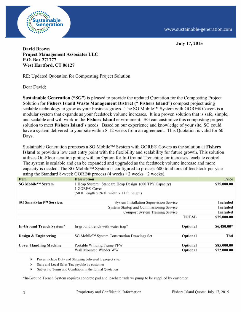
Item Description Price SG Mobile™ System 1 Heap System: Standard Heap Design (600 TPY Capacity)
1 GORE® Cover (50 ft. length x 26 ft. width x 11 ft. height)
$75,000.00
SG SmartStart™ Services System Installation Supervision Service Included System Startup and Commissioning Service Included Compost System Training Service Included TOTAL $75,000.00 In-Ground Trench System* In-ground trench with water trap* Optional $6,480.00* Design & Engineering SG Mobile™ System Construction Drawings Set Optional Tbd Cover Handling Machine Portable Winding Frame PFW Optional $85,000.00 Wall Mounted Winder WW Optional $72,000.00
Ø Prices include Duty and Shipping delivered to project site. Ø State and Local Sales Tax payable by customer Ø Subject to Terms and Conditions in the formal Quotation
*In-Ground Trench System requires concrete pad and leachate tank w/ pump to be supplied by customer

Proprietary and Confidential Information Fishers Island Quote: July 17, 2015 2
www.sustainable-‐generation.com
Our Quotation provides information relevant to the scope of the supply of equipment and services provided by SG for the SG Mobile™ System. Customer is responsible for construction. The project requirements and scope of work will need to be further refined as part of the design process. Any equipment and services (such as mixing, screening, front end loader, etc.) not related to the composting system shall be provided by the owner’s project team or supplied by others. Sincerely, Brett Hoyt Sales VP Sustainable Generation 110 South Poplar Street Wilmington, DE 19801 Phone: 303.699.1585 Email: [email protected] Website: www.sustainable-generation.com

Proprietary and Confidential Information Fishers Island Quote: July 17, 2015 3
www.sustainable-‐generation.com
SG Mobile™ System Composting Solution Quotation for Fishers Island (“CUSTOMER”)
Date: July 17, 2015
Prepared by: Brett Hoyt / phone: 303.699.1585 / email: [email protected]
Prepared for:
David Brown
Project Management Associates LLC P.O. Box 271777 West Hartford, CT 06127
SG Mobile™ System - Standard Heap Design
Mobile System Unit GORE® Cover On-Floor Aeration
Proprietary and Confidential Information Fishers Island Quote: July 17, 2015 4
www.sustainable-‐generation.com
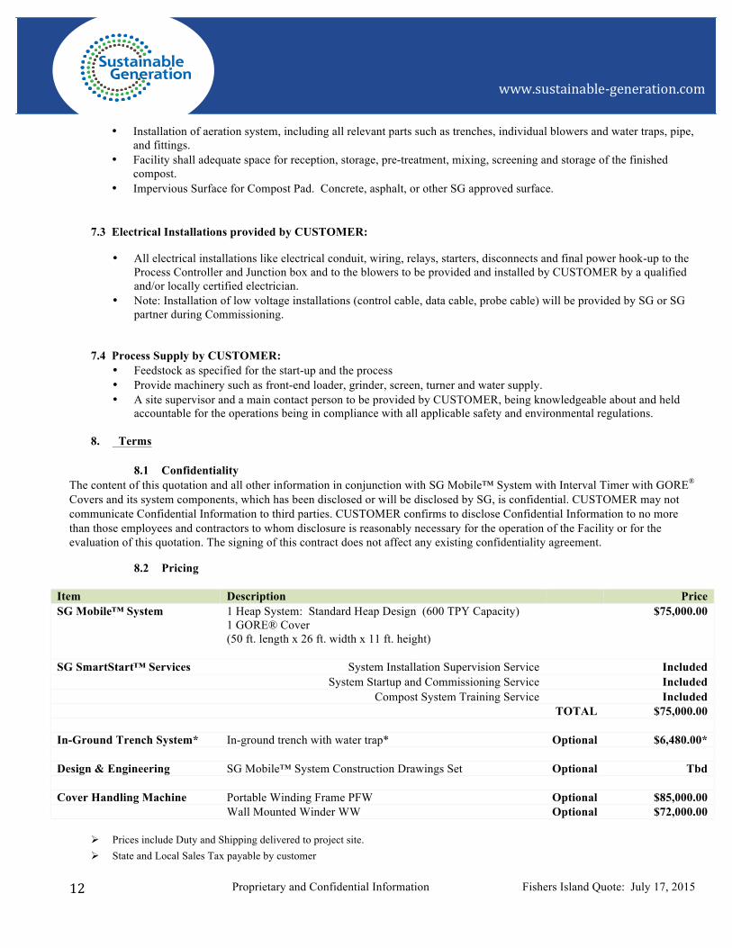
1. General
1.1. Input Materials and Volumes:
Input Materials1 Green Waste/ Yard Waste
Food Waste – pre/post Consumer
Source Separated Organics
Volume: US Units1: 8 Week Process
Input ton/year: 600
Input ton/month: 50
Input ton/week: 12
Specific Weight [lbs./yard³]: 925
1 Data provided to SG by CUSTOMER for the purpose of an agreed upon system sizing.
1.2. Number of windrows
Phase 1 –High Rate Composting 1 Covered
Phase 2 - Maturation 0 Covered
Phase 3 - Finishing 0 Uncovered
Total 1 Batch Processing
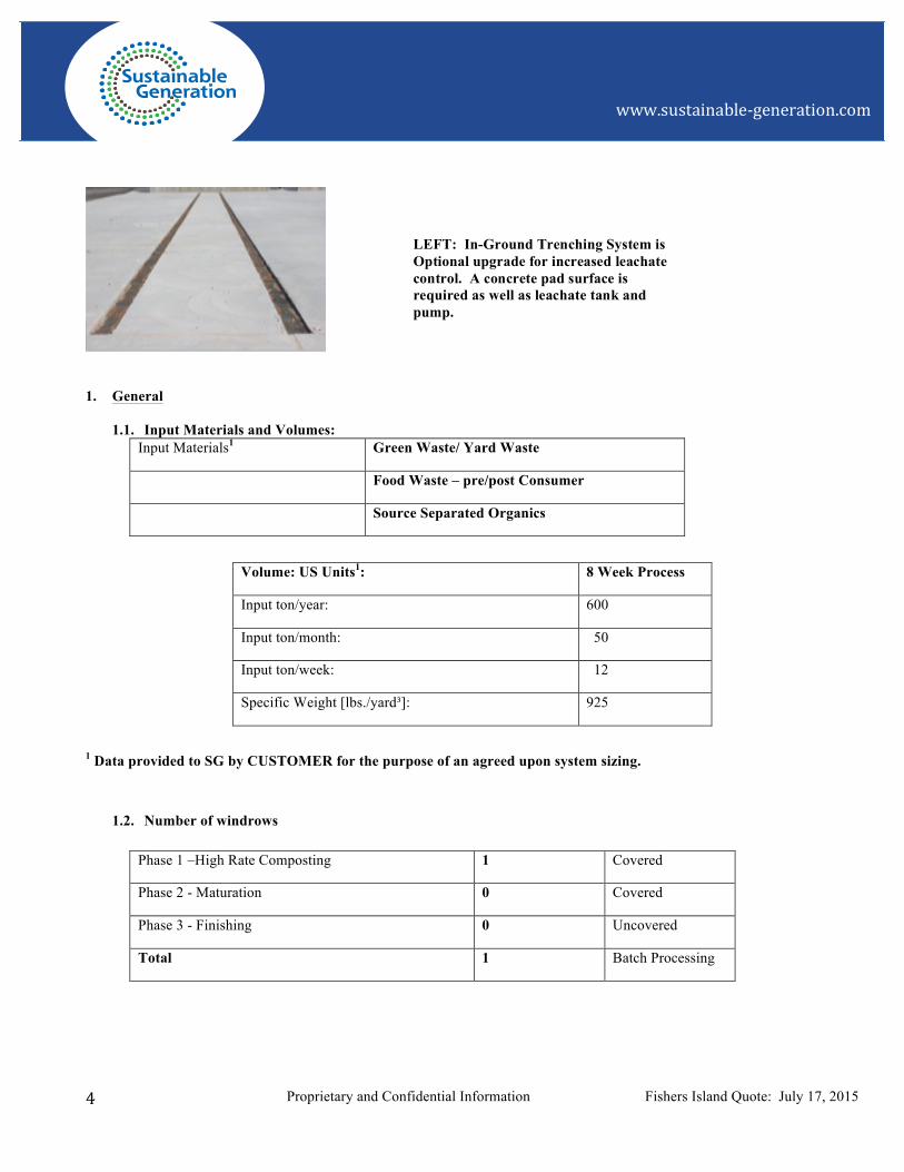
LEFT: In-Ground Trenching System is Optional upgrade for increased leachate control. A concrete pad surface is required as well as leachate tank and pump.

Proprietary and Confidential Information Fishers Island Quote: July 17, 2015 5
www.sustainable-‐generation.com
1.3. Heap Design and Windrow Dimensions
Standard Heap Design
Length 50 ft.
Width 26 ft.
Height 11.5 ft.
Feedstock Mix Recipe Density 925 lbs./ y2
1.4. Compost Pad: Recommended Minimum Surface Area2
Configuration* Total Windrows Length (ft.) x Width (ft.)
On Floor Aeration Design 1 130 ft. x 32 ft.
2 130 ft. x 64 ft.
3 130 ft. x 96 ft.
In-Ground Trenching Design
1 90 ft. x 32 ft.
2 90 ft. x 65 ft.
3 90 ft. x 96 ft.
*Inclusive of Active Composting Pad, Driving Space and room to pull On Floor Pipe and using Cover Winder Machine to place and remove GORE® Covers.
Distance Between Windrows 6 ft.
2Layout, configuration and driving space shall be confirmed by the CUSTOMER’S professional design engineer and according to local codes and regulations.
1.5. Cover Handling Method: (Optional Equipment)
Item Quantity Description
Portable Winding Frame Tbd Tow behind, Portable Winder

Proprietary and Confidential Information Fishers Island Quote: July 17, 2015 6
www.sustainable-‐generation.com
2. SG Mobile™ System with GORE® Covers Scope of Supply:
SG Mobile™ System with Gore Covers includes the following:
2.1 Installation Guide, which includes Specifications and Drawings for the Design Team:
Layout and drawings provided by SG are for the purpose of guiding the design configuration and are not to be used for construction. Customer is responsible for construction. CUSTOMER agrees to consult with a professional engineer and design according to local code and regulations.
• Basic Site Layout for the Phase I, Phase II and Phase III areas of the composting pad including the push walls, bunker walls, and driving area
• Drawings and Specifications for the cover winding system provided. • Drawings and Specifications for the Aeration System • Basic wiring diagrams and power/electrical system drawing to be finalized according to local standards and regulations
by a qualified and/or locally certified electrician.
2.2 GORE® Covers
Item Quantity Description
GORE® Cover 1 Batch Processing
Tie Down Straps Included
Cover Perimeter Weighting System Included
LEFT: SG Mobile™ System with optional In-Ground Trenching System.

Proprietary and Confidential Information Fishers Island Quote: July 17, 2015 7
www.sustainable-‐generation.com
2.3 Mobile System Units
Item Quantity Description
Portable Box Unit 1 Box Housing units for:
• Control System • Power System • Blower with Motor
2.4 Aeration System
Item: On-Floor Aeration System Per Heap Total
Blower Unit with Motor: 240/480v, single or three phase 1 1
On-Floor Aeration Piping 1 set 1 set
Cover Perimeter Weighting System 1 set 1 sets
In-Ground Trench System (Optional Equipment, Separately Quoted Line Item)*
Per Heap Total
Trenching for 50 ft. heaps 2 Sets 2 Sets
PVC Pipe and Angles 2 Sets 2 Sets
Water Traps 2 2
Caulking/ Sealant Included Included
*In-Ground Trench System requires concrete pad and leachate tank w/ pump to be supplied by customer
2.5 Control System
Component Per Heap Total
Process Control Unit (PCU) 1 1
Oxygen sensor (Phase 1 & 2) 1 (Phase 1 and 2 only) 1

Proprietary and Confidential Information Fishers Island Quote: July 17, 2015 8
www.sustainable-‐generation.com
Temperature Probes 1 1
Master Control Unit (MCU) 1 per site 1
Power System Junction Box 1 1
Cabling Analog/ Digital/ Fiber Optic or RF 1
Computer Laptop or Smart Device 1
Process Control Software Installed 1
Service Platform Software Installed 1
Process Control, Power System and cabling is a plug and play solution and will include the following features: • A Process Control Unit (PCU) for each windrow • Main power supply hook-up • Lockable power switch • Green control light for power on • Red control light for blower fail • Switch for blower manual ON/OFF/AUTO • 24 Volt transformer • NEMA 4x weather/ outdoor rated • Master Control Unit – Internet Ready
2.6 Spare Parts
1 Repair Kits for GORE® Cover including laminate 1
3 SG SmartStart™ Services
3.1 Technical Meetings, Site Supervision, Installation Guidance and Consultancy
Meeting Description
Pre-Design Included
Pre-Construction Included
Pre-Installation Included
Operator Training (1, 2) Included

Proprietary and Confidential Information Fishers Island Quote: July 17, 2015 9
www.sustainable-‐generation.com
Start Up and Commissioning Included
Service Platform: Technical Support Training Included
Training for Operators Reference Plant Duration (Days) Description
Training 1 Customer Site 3 During Commissioning
Training 2 Customer Site 1-2 1-3 Months after Startup
Consultancy
On Site Technical Support No Charge for first 12 months
On Site Technical Support $1000.00 per day per person plus travel /expenses
CUSTOMER will allow SG or SG Partner to access the plant after reasonable prior notice
4 Operations Manuals • Installation Manual for SG Mobile™ System • Operation Manual on GORE® Cover including safe handling guidelines • Operation Manual on the Control system (O2 sensor, Temp probe, Process Control software, blowers, aeration piping) • Standard operation manual on the Portable Winder machine • All documents will be provided in English on paper
5 SG Mobile™ System Design and Engineering - (Optional Service to be quoted separately, if needed. SG and CUSTOMER to define Scope of Work)
The design and engineering services include drawings associated with compost facility pad as follows:
• G001 Title Sheet, List of Drawings, Region & Vicinity Maps • G002 General, Civil and Mechanical Legends, Symbols • G003 Basis of Design & Process Flow Diagram • C001 Standard Details I • C002 Standard Details II • C100 Site Plan • C101 Grading and Paving Plan • C102 Grading and Paving Details • C103 Compost Heap Sections and Details • C104 Drainage and Leachate Piping Plan • C105 Drainage and Leachate Piping Details • C106 Blower Plan, Anchoring and Piping Details • C107 Blower Plan and Piping Details

Proprietary and Confidential Information Fishers Island Quote: July 17, 2015 10
www.sustainable-‐generation.com
• S001 Structural Abbreviations and Symbols • S002 Structural Standard Details I • S100 Structural Slab Sections & Details • S101 Structural Push Wall Sections & Details • E001 Electrical Legends, Symbols and Abbreviations • E100 Electrical Site, Power and Signal Plan • E101 Single Line Diagram • E102 Electrical Details • I001 P&ID Symbols and Abbreviations
The SG Mobile™ System Design and Engineering does NOT included:
• Ancillary elements outside the compost pad including Tipping Building, or other ancillary structures, storm water and treatment systems, leachate pump and storage system, odor control facilities and related.
• Also, does not include any adjacent equipment such as front-end loaders, grinders/mixers, and screens. • Topographic and boundary surveying to be provided by other. • Geotechnical recommendations to be provided by other.
6 Cover Winding Machine: (separately quoted line item)
Portable Winding Frame PWF:
The PWF is a portable machine moved into position by a frontend loader or vehicle using a standard trailer hitch mount. The operator must position the PWF in front of or behind the heap. The PWF is used to deploy the cover during heap construction and deconstruction. The PWF is designed and built specially for the GORE® Cover system for heaps 26 feet (8m) in width and up to 12 feet (3.5m) in height. Upon delivery SG will send technicians to construct the PWF at the compost site and conduct training on operations and maintenance. An Operating Manual will also be provided along with a troubleshooting guide. The PWF meets all California emission control standards and is capable to operate in extreme cold climates.
For the purpose of calculating operating costs, it has been SG’s experience that the PWF can deploy a cover for heap construction and deconstruction within a 30 minute or less time period. The PWF requires additional labor and requires the use of cables and pulley and winch system to move the cover. The PWF uses a gas engine. Engine maintenance can be accomplished locally.
BELOW: Portable Winding Frame: PWF: For use with GORE® Cover

Proprietary and Confidential Information Fishers Island Quote: July 17, 2015 11
www.sustainable-‐generation.com
Wall Mounted Winder WW:
The Wall Mounted Winder (WW) is similar to the Portable Winding Frame except that it is not on wheels, but rather attaches to push-wall of the heap or support beam mounted. It uses a track and rail system to move the unit into position. A cable, pulley and winch system is used to deploy or uncover a heap in less than 30 minutes. Upon delivery SG will send technicians to construct the PWF at the compost site and conduct training on operations and maintenance. An Operating Manual will also be provided along with a troubleshooting guide.
Above: Wall Mounted Winder (WW): For use with GORE® Cover
1. CUSTOMER Responsibilities
Customer is responsible for construction and installation. CUSTOMER agrees to consult with a professional engineer and design according to local code and regulations.
7.1 Installation Supply:
• Provide a staging area for shipping containers and unloading the equipment into a secure and dry area (housing for the control system, space for the other parts).
• Provide workspace and lay-down area for the partner companies including communication (telephone, fax and internet).
• Provide access to standard hand tools (wrenches, hammers, screwdrivers, drill etc.) and temporary power • Provide front-end loader, forklift, crane and trained equipment operators. • Note: The Container holding the cover winder machine has to be unloaded to the ground without being opened or
any parts removed. Container shall only be opened by SG or SG partner.
7.2 Site Construction, Installations, and Parts provided by CUSTOMER:
• Site preparation as per permit requirements adapted to local specifications. • All concrete, mechanical, electrical work for construction and installation of compost pad, bunkers, push walls, and
electrical power.
Proprietary and Confidential Information Fishers Island Quote: July 17, 2015 12
www.sustainable-‐generation.com
• Installation of aeration system, including all relevant parts such as trenches, individual blowers and water traps, pipe, and fittings.
• Facility shall adequate space for reception, storage, pre-treatment, mixing, screening and storage of the finished compost.
• Impervious Surface for Compost Pad. Concrete, asphalt, or other SG approved surface.
7.3 Electrical Installations provided by CUSTOMER:
• All electrical installations like electrical conduit, wiring, relays, starters, disconnects and final power hook-up to the Process Controller and Junction box and to the blowers to be provided and installed by CUSTOMER by a qualified and/or locally certified electrician.
• Note: Installation of low voltage installations (control cable, data cable, probe cable) will be provided by SG or SG partner during Commissioning.
7.4 Process Supply by CUSTOMER:
• Feedstock as specified for the start-up and the process • Provide machinery such as front-end loader, grinder, screen, turner and water supply. • A site supervisor and a main contact person to be provided by CUSTOMER, being knowledgeable about and held
accountable for the operations being in compliance with all applicable safety and environmental regulations.
8. Terms
8.1 Confidentiality The content of this quotation and all other information in conjunction with SG Mobile™ System with Interval Timer with GORE® Covers and its system components, which has been disclosed or will be disclosed by SG, is confidential. CUSTOMER may not communicate Confidential Information to third parties. CUSTOMER confirms to disclose Confidential Information to no more than those employees and contractors to whom disclosure is reasonably necessary for the operation of the Facility or for the evaluation of this quotation. The signing of this contract does not affect any existing confidentiality agreement.
8.2 Pricing
Item Description Price SG Mobile™ System 1 Heap System: Standard Heap Design (600 TPY Capacity)
1 GORE® Cover (50 ft. length x 26 ft. width x 11 ft. height)
$75,000.00
SG SmartStart™ Services System Installation Supervision Service Included System Startup and Commissioning Service Included Compost System Training Service Included TOTAL $75,000.00 In-Ground Trench System* In-ground trench with water trap* Optional $6,480.00* Design & Engineering SG Mobile™ System Construction Drawings Set Optional Tbd Cover Handling Machine Portable Winding Frame PFW Optional $85,000.00 Wall Mounted Winder WW Optional $72,000.00
Ø Prices include Duty and Shipping delivered to project site. Ø State and Local Sales Tax payable by customer

Proprietary and Confidential Information Fishers Island Quote: July 17, 2015 13
www.sustainable-‐generation.com
8.3 Payment Terms
Requirement Rate Action/ Deliverable Invoiced
Payment #1 50% Notice to Proceed/ Production/ Ship Upon Agreement Signing
Payment #2 50% Shipment/ Installation Commissioning of System
8.4 Time schedule: • SG and Customer will set a specific time schedule for: when, what, in which way Action Items/ Deliverables will be
received after this contract is signed. • Delivery date to be discussed. Customer will issue to SG a Notice to Proceed/ Production; thereafter Customer
should allow 8-12 weeks lead-time for the shipment to arrive on-site after receiving Payment #1.
8.5 General terms and conditions The Terms and Conditions of Sustainable Generation (attached) shall apply. All other terms are expressly rejected. In the event of any inconsistency between the terms and conditions of this Quotation and the Terms and Conditions of Sustainable Generation LLC, the terms and conditions of the Quotation will prevail.
8.6 Warranties and Guarantees
• Sustainable Generation (SG) warrants that the system as specified in this quotation is designed to process a minimum amount of feedstock as specified in Section 1.1 for a period of 1 year, provided that SG Mobile™ System with GORE® Covers was operated in accordance with all Operation Manuals, Trainings and all other relevant instructions or information provided by SG. Warranty will start from date of commissioning or at the latest 6 months after shipment. In the event of claims to this warranty CUSTOMER shall provide access to all available process data.
• GORE® Cover Manufacture’s Warranty: W.L. Gore & Associates (Gore) is liable for defects in material caused by failure of tensile strength of the GORE® Cover and all GORE® Covers which contain such defects have to be repaired, replaced or performed anew at Gore’s option. This warranty shall be valid for a period of 4 years from date of commissioning of the defect GORE® Cover. For any claim to this warranty arising within 24 month of the warranty period the repair, replacement or performance anew is free of charge; for the remaining warranty period a pro rata warranty shall apply according to the following formula: remedial action = [(total warranty period of 48 month – service life reached) ÷ (total warranty period)] x purchase price.
• For all other supplies of SG Mobile™ Cover system components which contain defects in material the statutory warranty with a warranty period of 12 month applies, provided that supplies were used in accordance with Operation Manual, Trainings and all other relevant instruction.
• Any liability as set forth in this section is in each case limited to the value of the specific component project in connection with which the damaging event has occurred.
• Under no circumstances shall SG or W.L.Gore & Associates be liable for indirect or consequential damages, loss of profits or loss of business opportunity
• CUSTOMER is solely responsible to operate SG Mobile™ System with GORE® Covers in compliance with applicable law.
• Subject to pricing and terms & conditions as described in the formal Quotation

Proprietary and Confidential Information Fishers Island Quote: July 17, 2015 14
www.sustainable-‐generation.com
9. Cancellation
CUSTOMER may terminate or cancel the Order by written notice to SG. Orders cancelled prior to the issuance of a Notice to Proceed for production and shipment and will be subject to a cancellation charge based on the percentage of work completed. The cancellation charge may not exceed an amount of $25,000.00 (Twenty Five Thousand Dollars) in total.
Orders terminated or cancelled by CUSTOMER after the issuance of a Notice to Proceed for production and shipment will be subject to the Sustainable Generation LLC Terms and Conditions attached to this quote.
10. Applicable Law; Jurisdiction
This Quotation is governed by the substantive law of the State of Delaware, without regard to its principles regarding the conflict of laws. The United Nations Convention for the international sale of goods shall not apply. The parties agree to the jurisdiction of the United States District Court for the District of Delaware and the courts of the State of Delaware for the resolution of any litigation relating to this Agreement.

Proprietary and Confidential Information Fishers Island Quote: July 17, 2015 15
www.sustainable-‐generation.com
Contract partner and seller is Sustainable Generation, LLC of Wilmington, Delaware. Validity of this Quotation is 60 Days from date of offer. Please return approved quotation by: • Scan/email to: [email protected] • Mail original to: Sustainable Generation, LLC 110 South Poplar Street, Suite 400 Wilmington, DE 19801 Offered: July 17, 2015 Quotation Accepted:
__________________________ Signature: ______________________________ Brett Hoyt Sales VP Print Name: _____________________________ Sustainable Generation LLC 110 South Poplar St., Suite 400 Title: ______________________________ Wilmington, DE 19801 Company: ______________________________ Date: ______________________________
16
APPENDIX: Sustainable Generation’s Terms and Conditions
(Page intentionally left blank)

TERMS AND CONDITIONS of Sustainable Generation, LLC
1. AMOUNT AND TYPE OF GOODS. Seller agrees to sell and Buyer agrees to buy the quantity and type of products and/or services (the “Products”) which are described in this Agreement.
2. ENTIRE AGREEMENT: This Agreement represents the entire integrated agreement between Buyer and Seller and supersedes all prior negotiations, representations or agreements, either written or oral. These terms may be amended only by a written instrument signed by both Buyer and Seller.
3. INSPECTION, CLAIMS FOR DEFECTS OR LATE DELIVERY: Buyer shall have the right to inspect the Products after delivery. Buyer shall give Seller prompt written notice of any damaged, defective or non-conforming Products and shall make all rejected Products available to Seller for inspection. Failure of Buyer to give written notice or rejection to Seller within sixty (60) days from the date of delivery constitutes Buyer’s irrevocable acceptance of the Products. Buyer is entitled to inspect the Products at any stage of manufacturing , but Seller reserves the right to restrict access to certain machinery, processes, and information that Seller deems proprietary. Seller shall have no obligation to replace or provide credit for Products claimed to be defective unless Seller receives representative samples of the Products and an opportunity to examine the Products at a place convenient to the Seller. In the event that Buyer elects to accept a part of a delivery, it is agreed that the portion of Products rejected shall be returned to Seller within thirty (30) days following Seller’s authorization.
4. DELIVERIES: The delivery of the Products shall be made, in a single or in multiple lots, as specified in the Agreement, or within a reasonable time thereafter. The delivery schedule shall be considered extended by a period of time equal to the time lost due to any delay for causes beyond Seller’s reasonable control. Seller's failure to make delivery of any item or to meet any delivery date shall not affect future deliveries or excuse Buyer from paying any installment when due. Buyer’s failure to pay any installment when due shall excuse Seller from making further deliveries. Buyer shall confirm the suitability of Seller's standard manufacturing lead times prior to placing orders. Seller reserves the right to charge expediting fees for deliveries requested in advance of Seller's standard lead-time. With respect to each delivery obligation contained in this Agreement: (i) Tender of a shipment to any licensed carrier shall constitute delivery to Buyer; (ii) Seller shall use its best efforts to deliver in accord with the schedule specified in this Agreement. Any delivery not in dispute shall be paid for in accordance with that order's terms by Buyer, regardless of any dispute as to other delivered or undelivered goods. Seller is not obligated to package goods for outside storage. Deliveries of up to ten percent (10%) above or below quantities specified in the order shall be accepted by Buyer and the invoice price will be adjusted accordingly. Unless otherwise specified by Seller, delivery terms are to be Ex Works (Incoterms 2000) Seller's manufacturing site.
5. TITLE; RISK OF LOSS: Unless otherwise agreed by the parties, risk of loss or damage to the Products shall pass to the Buyer upon delivery. Buyer shall receive title to the Products upon Seller’s receipt of payment in full for the Products delivered.
6. PRICING OF BULK PURCHASE ORDERS: Unless otherwise agreed by the parties, installment deliveries extending over six months from the original order date will be invoiced at Seller’s then-prevailing unit price.
7. WARRANTY: Seller warrants that at the time of delivery, the Products are free from defects in materials and workmanship and conform to Seller’s specifications, and, if applicable, acceptance criteria to which Seller has agreed in writing. Buyer retains sole responsibility for determining whether the Products are fit for the intended use, and for suitability of qualification and acceptance criteria. Claims for defects must be received by Seller within one (1) year from delivery of the Product on which the claim is based. Buyer's remedy will be limited to repair, replacement or refund for those Products which Seller verifies are defective. This warranty is conditioned upon (a) proper storage, installation, use, operation, and maintenance of the Products, (b) Buyer keeping accurate and complete records of operation and maintenance during the warranty period and providing Seller access to those records, and (c) modification or repair of the Projects only as authorized by Seller. Failure to meet any such conditions renders the warranty null and void. Seller is not responsible for normal wear and tear.
THIS WARRANTY IS IN LIEU OF ALL OTHER WARRANTIES WHETHER EXPRESS OR IMPLIED INCLUDING ANY IMPLIED WARRANTY OF MERCHANTIBILITY OR FITNESS FOR A PARTICULAR PURPOSE.
8. INDEMNITY AGAINST INFRINGEMENT: Seller will, at its expense, defend Buyer against any claim by a third party that the products delivered hereunder infringe any intellectual property right and will pay all costs, damages, and attorney's fees that a court finally awards as a result of such claim. To qualify for such defense and payment, Buyer must give Seller prompt written notice of such claim and allow Seller to control, and fully cooperate with Seller in, the defense and all related settlement negotiations. Seller shall have no obligation with respect to any claim of direct or contributory infringement based upon modification of the products furnished by Seller or their combination, operation, or use. Buyer shall hold Seller harmless against any such claim arising out of compliance with specifications furnished by Buyer. This Article 8 states Seller's entire obligation to Buyer regarding claims of infringement, whether direct or contributory, involving intellectual property rights of third parties. Neither party shall have the obligations set forth in this Article 8 if an infringement claim is brought against a party protected from such a claim pursuant to government regulations.
9. CHANGES: Either party may at any time propose changes to the specification or scope of Products. All changes to the specification or delivery schedule will require a written agreement between the parties which will, at minimum, include the changes in the scope, delivery schedule and resulting change in price. Seller reserves the right to improve and make changes to Products sold hereunder without notice or approval of Buyer, except for changes that materially modify the form, fit or function of the Product contained the specifications.
10. CANCELLATION: Except as otherwise provided in the Agreement, orders cancelled by Buyer other than for default of Seller will be subject to a cancellation charge based on the percentage of work completed as a percentage of the contract price or such other reasonable charge

as Seller may apply. Buyer will be entitled to receive any Products for which Seller has received payment in full. Seller, in its sole discretion may waive its claim for the value of work in progress. Buyer's cancellation request(s) must be in writing.
11. TECHNICAL DATA AND PROPRIETARY INFORMATION: Seller has no obligation to provide technical data other than its standard finished Product inspection data. Seller has no obligation to perform, and this is not an Agreement for, research, developmental or experimental work. Seller has no obligation to disclose, convey rights or allow access to technical, financial, or other information protected by it as proprietary or to indemnify Buyer for such refusal to disclose.
12. PAYMENT: Buyer shall pay Seller for the Products by paying all invoiced amounts in U.S. Dollars, without set-off, reduction or adjustment within thirty (30) days from the invoice date. For each calendar month, or fraction thereof, that payment is late, Buyer shall pay interest computed at the rate of 1.5% per month, or the maximum rate permitted by law, on the overdue balance. If it is necessary for Seller to enforce any provision of this Agreement, Buyer agrees to reimburse Seller for all legal and other reasonable costs related thereto, including attorneys’ fees, court costs, administrative time, and other collection costs, whether or not Seller initiates court proceedings. Buyer shall also pay all costs, attorney’s fees, filing fees, and/or administrative fees in the event Buyer appeals any decision or order from a judicial proceeding against Seller. Seller reserves the right to alter Buyer's credit limit, if any, at any time, or to require payment in full for any order or prior order before delivery. If Buyer fails to pay any invoices when due, Seller may terminate this Agreement and cancel or delay all future deliveries without otherwise affecting Seller's rights hereunder. As partial payment of sums due hereunder, Seller may accept any check or other tender of payment without entering into an accord and satisfaction and without prejudice to the Seller's right to the remainder due or to become due hereunder notwithstanding any terms or conditions endorsed on or stated in any communication related to such check or other tender. Seller may apply any amounts tendered by Buyer as Seller determines, in its sole discretion, whether under this Agreement or otherwise. All prices quoted are exclusive of taxes.
13. FORCE MAJEURE: Seller shall not be liable for any delay in delivery or for non-delivery, in whole or in part caused by the occurrence of any contingency beyond the control either of Seller or suppliers to Seller, including but not limited to war (declared or not), sabotage, insurrection, rebellion, riot or other act of civil disobedience, act of public enemy, failure or delay in transportation, act of any government or any agency or subdivision thereof, judicial action, labor dispute, fire, accident, explosion, epidemic, quarantine restrictions, storm, flood, earthquake, shortage of labor, fuel, raw material or machinery or technical failure, where Seller has exercised ordinary care in the prevention thereof. If any contingency occurs, Seller may allocate production and deliveries among Seller's customers.
14. REPRESENTATIONS AND CERTIFICATIONS: Seller makes no representations or certifications in connection with this Agreement except those which are expressly contained within these Terms of Sale and, if any, those provided separately which are signed and dated by the Seller and made exclusively applicable to this Agreement.
15. CONFIDENTIALITY: Buyer acknowledges that the content of this Agreement and all other information provided in conjunction with GORE® Cover and its system components, which has been disclosed or will be disclosed by Seller or Gore is Confidential Information. Buyer agrees to use the Confidential Information only in connection with the use of the Products and take reasonable measures to prevent disclosure of the Confidential Information to third parties. The Buyer also agrees that it will disclose Confidential Information only to those employees whom disclosure is necessary and will take the necessary steps to subject its employees to the terms of this provision. The Buyer’s obligations hereunder shall not apply if Confidential Information is required to be disclosed by valid legal process, provided that the Buyer shall promptly notify Seller in advance of such disclosure and reasonably cooperate in Seller’s attempts to maintain the confidentiality of the Confidential Information. The terms of this Paragraph shall survive termination of the Agreement for any reason.
16. LIMITATION OF LIABILITY: The total liability of Seller for call claims of any kind arising from or related to the formation, performance or breach of this Agreement, or any Products or Services, shall not exceed (i) the Agreement price, or (ii) if Buyer places multiple order(s) under this Agreement, the price of each particular order for all claims arising from or related to that order.
17. SAVINGS CLAUSE: If any provision of this Agreement is found to be void or unenforceable, the remainder of the Agreement shall not be affected. The parties will endeavor to replace any such void or unenforceable provision with a new provision that achieves substantially the same practical and economic effect and is valid and enforceable.
18. COUNTERPARTS: This Agreement may be executed in multiple counterparts that together shall constitute one Agreement.
19. APPLICABLE LAW; JURISDICTION: This Agreement is governed by the substantive law of the State of Delaware, without regard to its principles regarding the conflict of laws. The United Nations Convention for the international sale of goods shall not apply. The parties agree that the US District Court for the District of Delaware or the Courts of the State of Delaware have exclusive jurisdiction over the resolution of disputes arising under this Agreement. The parties hereby expressly agree to personal jurisdiction within the State of Delaware.
SG T&C’s April 2014
Draft: February5, 2016 Consolidated Facilities Planning Report
Fishers Island Waste Management District
Appendix B
Consolidated Facility Plans at Compost Station - Site and Utility Layout - Grading and Drainage Design - Construction Details (2 Sheets) - Erosion & Sedimentation Control
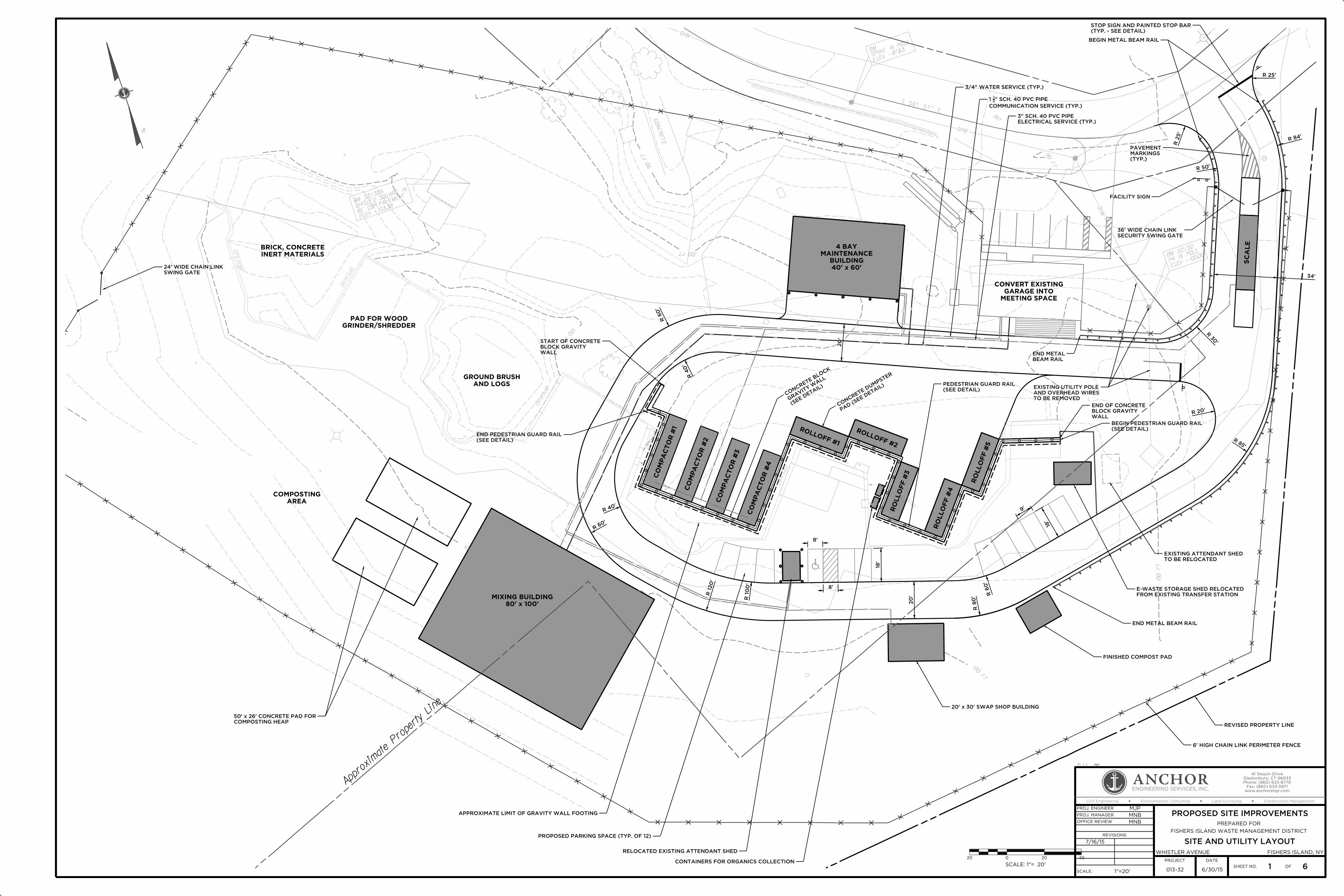
ELEV = 87.63
SPIKE
IN POLE
BM
BIT
OHW
S 56° 57" E
OHW
(removed
)
CO
NC
RE
TE
90 F
T
OHW
90 F
T
OH
W
DIR
T
OP
ENIN
G
OP
ENIN
G
ELEV = 10
0.00
PK IN
POLEBM 22/3
2
OPE
NIN
G
OP
ENIN
G
OPE
NIN
G
OP
ENIN
G
OH
W
100 F
T
OPE
NIN
G
OP
ENIN
G
ELEV = 10
3.38
NE COR. P
AVEMENT
CHISLED
SQUARE IN
BM 22/3
2A
+
100 FT
+
100 FT
+
+
100 FT
+
OP
ENIN
G
100 FT
+
+
WG
+
+
+
Approximate
Property
Line
0
SCALE: 1"= 20’
20 20 40
ENGINEERING SERVICES, INC.
ANCHOR
Civil Engineering Land Surveying
www.anchorengr.com
Fax: (860) 633-5971
Phone: (860) 633-8770
Glastonbury, CT 06033
41 Sequin Drive
PROJ. ENGINEER
PROJ. MANAGER
OFFICE REVIEW
PROJECT DATE
MJP
MNB
MNB
REVISIONS
7/16/15
SCALE: 1"=20’
WHISTLER AVENUE
PREPARED FOR
FISHERS ISLAND WASTE MANAGEMENT DISTRICT
PROPOSED SITE IMPROVEMENTS
SITE AND UTILITY LAYOUT
SHEET NO. OF1 6
Environmental Consulting Construction Management
6/30/15
FISHERS ISLAND, NY
013-32
J:\ \ \ .dgn
SC
AL
E
MEETING SPACE
GARAGE INTO
CONVERT EXISTING
AREA
COMPOSTING
CO
MP
AC
TO
R #
1
CO
MP
AC
TO
R #
2
CO
MP
AC
TO
R #
3
CO
MP
AC
TO
R #
4
ROLLOFF #1
ROLLOFF #2
RO
LL
OFF #
3
RO
LL
OFF #
4
RO
LL
OFF #
5
80’ x 100’
MIXING BUILDING
40’ x 60’
BUILDING
MAINTENANCE
4 BAY
20’
20’
(SEE
DETAIL)
GRAVI
TY W
ALL
CON
CRETE BLO
CK
PAD (S
EE DETA
IL)
CON
CRETE DUM
PSTER
34’
25’
R
25’R
50’R
84’R
20’R
85’
R
30’
R
80’
R
60’
R
120’
R 10
0’
R
60’
R
40’
R
60’
R
40’
R
8’
8’
18’
9’
18’
(SEE DETAIL)
END PEDESTRIAN GUARD RAIL
WALL
BLOCK GRAVITY
START OF CONCRETE
(SEE DETAIL)
PEDESTRIAN GUARD RAIL
BEAM RAIL
END METAL
WALL
BLOCK GRAVITY
END OF CONCRETE
(SEE DETAIL)
BEGIN PEDESTRIAN GUARD RAIL
TO BE RELOCATED
EXISTING ATTENDANT SHED
END METAL BEAM RAIL
FINISHED COMPOST PAD
6’ HIGH CHAIN LINK PERIMETER FENCE
REVISED PROPERTY LINE
20’ x 30’ SWAP SHOP BUILDING
CONTAINERS FOR ORGANICS COLLECTION
RELOCATED EXISTING ATTENDANT SHED
PROPOSED PARKING SPACE (TYP. OF 12)
APPROXIMATE LIMIT OF GRAVITY WALL FOOTING
COMPOSTING HEAP
50’ x 26’ CONCRETE PAD FOR
FROM EXISTING TRANSFER STATION
E-WASTE STORAGE SHED RELOCATED
TO BE REMOVED
AND OVERHEAD WIRES
EXISTING UTILITY POLE
BEGIN METAL BEAM RAIL
FACILITY SIGN
ELECTRICAL SERVICE (TYP.)
3" SCH. 40 PVC PIPE
COMMUNICATION SERVICE (TYP.)
" SCH. 40 PVC PIPE21
1
3/4" WATER SERVICE (TYP.)
AND LOGS
GROUND BRUSH
INERT MATERIALS
BRICK, CONCRETE
GRINDER/SHREDDER
PAD FOR WOOD
(TYP. - SEE DETAIL)
STOP SIGN AND PAINTED STOP BAR
(TYP.)
MARKINGS
PAVEMENT
SECURITY SWING GATE
36’ WIDE CHAIN LINK
SWING GATE
24’ WIDE CHAIN LINK

97
97
100
97.5
104
94
96
94
94
9088
8684
92
96
98
93.5 +
93.7 +
93.9 +
+
96.6
+
96.2
+
96.2
102
100
98
+
105.8
105.7
+
+
96.9
+
96.6
+
97.2
105.7
+
106.3
+
+
97.1
+
97.1
+
97.6
+
96.7
+
96.6
+
105.2
+
105.2
105.6
+
105.8
+
105.5
105
+
105.5
102
105
104
104.5
104.5
104
102
104
102100
100989
6949
290
93
+
96.5
93
+
105.7
105.9
+
+
99.5
+
101.0
+
97.3
92.5 +
ELEV = 87.63
SPIKE IN POLE
BM
BIT
OH
W
S 56° 57" E
OH
W
HY
D
(re
moved)
CO
NC
RE
TE
90 F
T
OHW
90 F
T
OH
W
DIR
T
OPE
NIN
G
OP
ENIN
G
ELEV = 100.00
PK IN POLE
BM 22/32
OP
ENIN
G
OP
ENIN
G
OP
ENIN
GOPENING
OH
W
100 F
T
OP
ENIN
G
OPENING
ELEV = 103.38
NE COR. PAVEMENT
CHISLED SQUARE IN
BM 22/32A
100 F
T
100
FT
100 FT
OPE
NIN
G
100 F
T
INV.=90.7
T.F.=94.7
CB 100
SPILLWAY
RIPRAP
0
SCALE: 1"= 20’
20 20 40
INV.=92.0
T.F.=96.0
CB 101
S=1.7%
76’-15" HDPE
S=1.8%
72’-15" HDPE
COMPACTED.
TO BE BACK FILLED WITH SOIL AND
STRUCTURE TO BE DEMOLISHED. AREA
CEILING OF UNDERGROUND CONCRETE
COMPACTED.
TO BE BACK FILLED WITH SOIL AND
STRUCTURE TO BE DEMOLISHED. AREA
CEILING OF UNDERGROUND CONCRETE
MIN. SLOPE @ 1%
30’- 6" SCH 40 PVC
INV.=89.4
WITH RIPRAP SPLASH PAD
FLARED END OUTLET (HDPE)
ENGINEERING SERVICES, INC.
ANCHOR
Civil Engineering Land Surveying
www.anchorengr.com
Fax: (860) 633-5971
Phone: (860) 633-8770
Glastonbury, CT 06033
41 Sequin Drive
PROJ. ENGINEER
PROJ. MANAGER
OFFICE REVIEW
PROJECT DATE
MJP
MNB
MNB
REVISIONS
SCALE: 1"=20’
WHISTLER AVENUE
PREPARED FOR
FISHERS ISLAND WASTE MANAGEMENT DISTRICT
PROPOSED SITE IMPROVEMENTS
GRADING & DRAINAGE DESIGN
SHEET NO. OF2 6
Environmental Consulting Construction Management
6/30/15
FISHERS ISLAND, NY
013-32
J:\ \ \ .dgn
SC
ALE
FF=96.3
40’ x 60’
BUILDING
MAINTENANCE
4 BAY
1.1%
1.0%
1.5%
FF=94.0
MEETING SPACE
GARAGE INTO
CONVERT EXISTING
1.3%
10.0
%
2.0
%
2.0
%
2.0
%
2.0
%
8.5%
FF=105.5
80’ x 100’
MIXING BUILDING
5.0
%
5.0
%
2.4%
1.3%
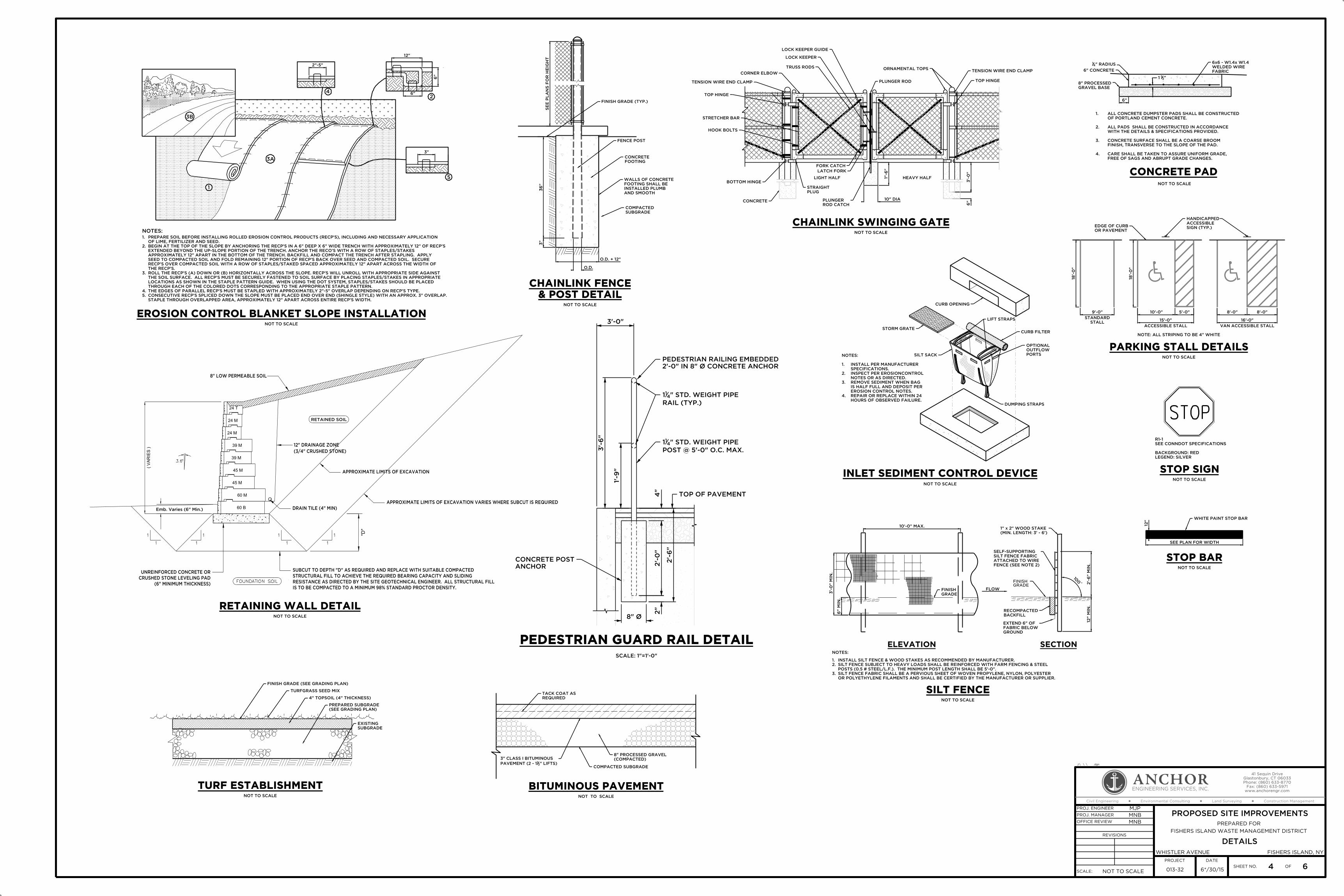
NOTES:
1. INSTALL PER MANUFACTURER
SPECIFICATIONS.
2. INSPECT PER EROSIONCONTROL
NOTES OR AS DIRECTED.
3. REMOVE SEDIMENT WHEN BAG
IS HALF FULL AND DEPOSIT PER
EROSION CONTROL NOTES.
4. REPAIR OR REPLACE WITHIN 24
HOURS OF OBSERVED FAILURE.
NOT TO SCALE
BITUMINOUS PAVEMENT
TACK COAT AS
REQUIRED
3" CLASS I BITUMINOUS
PAVEMENT (2 - 112" LIFTS)
8" PROCESSED GRAVEL
(COMPACTED)
COMPACTED SUBGRADE
NOT TO SCALE
SE
E P
LA
NS F
OR H
EIG
HT
3"
36"
O.D. + 12"
O.D.
FINISH GRADE (TYP.)
FENCE POST
FOOTING
CONCRETE
AND SMOOTH
INSTALLED PLUMB
FOOTING SHALL BE
WALLS OF CONCRETE
SUBGRADE
COMPACTED
& POST DETAIL
CHAINLINK FENCE
10" DIA
1"-6"
3’-0"
6"CONCRETE
TENSION WIRE END CLAMP
TENSION WIRE END CLAMP TOP HINGE
ORNAMENTAL TOPS
PLUNGER ROD
TRUSS RODS
CORNER ELBOW
TOP HINGE
BOTTOM HINGE
PLUG
STRAIGHT
ROD CATCH
PLUNGER
LOCK KEEPER GUIDE
FORK CATCH
STRETCHER BAR
HOOK BOLTS
LATCH FORK
LOCK KEEPER
LIGHT HALF HEAVY HALF
NOT TO SCALE
CHAINLINK SWINGING GATE
ACCESSIBLE STALLSTALL
STANDARD
VAN ACCESSIBLE STALL
NOTE: ALL STRIPING TO BE 4" WHITE
NOT TO SCALE
16’-0"
8’-0"8’-0"5’-0"10’-0"
15’-0"
9’-0"
18’-0"
18’-0"
SIGN (TYP.)
ACCESSIBLE
HANDICAPPED
OR PAVEMENT
EDGE OF CURB
PARKING STALL DETAILS
STOP
NOT TO SCALE
STOP SIGN
LEGEND: SILVER
BACKGROUND: RED
SEE CONNDOT SPECIFICATIONS
R1-1
WHITE PAINT STOP BAR
NOT TO SCALE
12"
SEE PLAN FOR WIDTH
STOP BAR
3B
3A
1
5
24
NOT TO SCALE
INLET SEDIMENT CONTROL DEVICE
NOT TO SCALE
FLOW
3’-0" M
IN.
NOTES:
OR POLYETHYLENE FILAMENTS AND SHALL BE CERTIFIED BY THE MANUFACTURER OR SUPPLIER.
SILT FENCE FABRIC SHALL BE A PERVIOUS SHEET OF WOVEN PROPYLENE, NYLON, POLYESTER3.
POSTS (0.5 # STEEL/L.F.). THE MINIMUM POST LENGTH SHALL BE 5’-0".
SILT FENCE SUBJECT TO HEAVY LOADS SHALL BE REINFORCED WITH FARM FENCING & STEEL 2.
INSTALL SILT FENCE & WOOD STAKES AS RECOMMENDED BY MANUFACTURER.1.
100� 2
’-6" M
IN.
12" M
IN.
GRADEFINISH
FENCE (SEE NOTE 2)
ATTACHED TO WIRE
SILT FENCE FABRIC
SELF-SUPPORTING
(MIN. LENGTH: 3’ - 6’)
1" x 2" WOOD STAKE
GROUND
FABRIC BELOW
EXTEND 6" OF
BACKFILL
RECOMPACTED
6" M
IN.
GRADE
FINISH
10’-0" MAX.
SILT FENCE
ELEVATION SECTION
NOT TO SCALE
TURFGRASS SEED MIX
FINISH GRADE (SEE GRADING PLAN)
(SEE GRADING PLAN)
PREPARED SUBGRADE
4" TOPSOIL (4" THICKNESS)
SUBGRADE
EXISTING
TURF ESTABLISHMENT
NOTES:
NOT TO SCALE
STAPLE THROUGH OVERLAPPED AREA, APPROXIMATELY 12" APART ACROSS ENTIRE RECP’S WIDTH.
CONSECUTIVE RECP’S SPLICED DOWN THE SLOPE MUST BE PLACED END OVER END (SHINGLE STYLE) WITH AN APPROX. 3" OVERLAP.5.
THE EDGES OF PARALLEL RECP’S MUST BE STAPLED WITH APPROXIMATELY 2"-5" OVERLAP DEPENDING ON RECP’S TYPE.4.
THROUGH EACH OF THE COLORED DOTS CORRESPONDING TO THE APPROPRIATE STAPLE PATTERN.
LOCATIONS AS SHOWN IN THE STAPLE PATTERN GUIDE. WHEN USING THE DOT SYSTEM, STAPLES/STAKES SHOULD BE PLACED
THE SOIL SURFACE. ALL RECP’S MUST BE SECURELY FASTENED TO SOIL SURFACE BY PLACING STAPLES/STAKES IN APPROPRIATE
ROLL THE RECP’S (A) DOWN OR (B) HORIZONTALLY ACROSS THE SLOPE. RECP’S WILL UNROLL WITH APPROPRIATE SIDE AGAINST3.
THE RECP’S.
RECP’S OVER COMPACTED SOIL WITH A ROW OF STAPLES/STAKED SPACED APPROXIMATELY 12" APART ACROSS THE WIDTH OF
SEED TO COMPACTED SOIL AND FOLD REMAINING 12" PORTION OF RECP’S BACK OVER SEED AND COMPACTED SOIL. SECURE
APPROXIMATELY 12" APART IN THE BOTTOM OF THE TRENCH. BACKFILL AND COMPACT THE TRENCH AFTER STAPLING. APPLY
EXTENDED BEYOND THE UP-SLOPE PORTION OF THE TRENCH. ANCHOR THE RECO’S WITH A ROW OF STAPLES/STAKES
BEGIN AT THE TOP OF THE SLOPE BY ANCHORING THE RECP’S IN A 6" DEEP X 6" WIDE TRENCH WITH APPROXIMATELY 12" OF RECP’S2.
OF LIME, FERTILIZER AND SEED.
PREPARE SOIL BEFORE INSTALLING ROLLED EROSION CONTROL PRODUCTS (RECP’S), INCLUDING AND NECESSARY APPLICATION1.
2"-5"
12"
6"
6"
3"
EROSION CONTROL BLANKET SLOPE INSTALLATION
DUMPING STRAPS
OPTIONAL
OUTFLOW
PORTS
CURB FILTER
LIFT STRAPS
STORM GRATE
CURB OPENING
SILT SACK
24 T
60 B
39 M
24 M
24 M
Emb. Varies (6" Min.)
FOUNDATION SOIL
RETAINED SOIL
45 M
60 M
45 M
39 M
(6" MINIMUM THICKNESS)
CRUSHED STONE LEVELING PAD
UNREINFORCED CONCRETE OR
"D"
1
1
1
1
1
1
1
1
DRAIN TILE (4" MIN)
APPROXIMATE LIMITS OF EXCAVATION VARIES WHERE SUBCUT IS REQUIRED
APPROXIMATE LIMITS OF EXCAVATION
(3/4" CRUSHED STONE)
12" DRAINAGE ZONE
8" LOW PERMEABLE SOIL
( V
ARIE
S )
IS TO BE COMPACTED TO A MINIMUM 98% STANDARD PROCTOR DENSITY.
RESISTANCE AS DIRECTED BY THE SITE GEOTECHNICAL ENGINEER. ALL STRUCTURAL FILL
STRUCTURAL FILL TO ACHIEVE THE REQUIRED BEARING CAPACITY AND SLIDING
SUBCUT TO DEPTH "D" AS REQUIRED AND REPLACE WITH SUITABLE COMPACTED
NOT TO SCALE
"211
" RADIUS41
FABRIC
WELDED WIRE
6x6 - W1.4x W1.4
6" CONCRETE
6"
(TYP.)
FREE OF SAGS AND ABRUPT GRADE CHANGES.
CARE SHALL BE TAKEN TO ASSURE UNIFORM GRADE,4.
FINISH, TRANSVERSE TO THE SLOPE OF THE PAD.
CONCRETE SURFACE SHALL BE A COARSE BROOM3.
WITH THE DETAILS & SPECIFICATIONS PROVIDED.
ALL PADS SHALL BE CONSTRUCTED IN ACCORDANCE2.
OF PORTLAND CEMENT CONCRETE.
ALL CONCRETE DUMPSTER PADS SHALL BE CONSTRUCTED1.
NOT TO SCALE
RETAINING WALL DETAIL
GRAVEL BASE
8" PROCESSED
CONCRETE PAD
ENGINEERING SERVICES, INC.
ANCHOR
Civil Engineering Land Surveying
www.anchorengr.com
Fax: (860) 633-5971
Phone: (860) 633-8770
Glastonbury, CT 06033
41 Sequin Drive
PROJ. ENGINEER
PROJ. MANAGER
OFFICE REVIEW
PROJECT DATE
MJP
MNB
MNB
REVISIONS
SCALE: NOT TO SCALE
WHISTLER AVENUE
PREPARED FOR
FISHERS ISLAND WASTE MANAGEMENT DISTRICT
PROPOSED SITE IMPROVEMENTS
DETAILS
SHEET NO. OF4 6
Environmental Consulting Construction Management
6*/30/15
FISHERS ISLAND, NY
013-32
J:\ \ \ .dgn
3’-0"
8" Ø
2’-6"
TOP OF PAVEMENT
2’-0" IN 8" Ø CONCRETE ANCHOR
PEDESTRIAN RAILING EMBEDDED
RAIL (TYP.)
" STD. WEIGHT PIPE411
POST @ 5’-0" O.C. MAX.
" STD. WEIGHT PIPE411
ANCHOR
CONCRETE POST
3’-6"
1’-9"
2"
2’-0"
4"
PEDESTRIAN GUARD RAIL DETAIL
SCALE: 1"=1’-0"

NOT TO SCALE
A
B
A
B
L
RE
DU
CE
R
SECTION A-A SECTION B-B
PLAN
TYPICAL
DETAIL ’’A’’
TYPE "C-L" CATCH BASIN (PRIVATE)
KNOCK OUT
1’-1"1’-10"1’-1"
8"4’-0"
5’-4"
6"
2" MIN.
1"
1"
3"
9"
C OF C.B
TYPE ’’C’’
CURB LINE FOR
SHOWN)
(TYPE "C-L"
PRECAST TOP
THE PERVIOUS BACKFILL
ABOVE THE BOTTOM OF
WALLS AT OR IMMEDIATELY
DRAINAGE OPENING IN 4
OF THE STRUCTURE
DEPTH 3’ BELOW THE TOP
THIS ELEVATION-MAXIMUM
PREVIOUS BACKFILL ABOVEFLOW LINE
DETAIL "A"
SEE
PRECAST TOP
6"
8" M
IN.
2’-0" M
IN. S
UM
P
"851’-1
BA
SE
RIS
ER(V
ARIE
S)
1’
MIN.
1’-6"
"432’-8
"211 "2
11
4’-4"
8"3’-0"
6"
CA
P A
ND R
ED
UC
ER
OP
ENIN
G I
N S
PA
CE
R
30" MAX.
JOINTS
MORTAR
FABRIC
WIRE
WELDED
FLOW LINE
AS DIRECTED.
ADJACENT TO CATCH BASIN
GRADING TO BE VARIED
NORMAL FINISHED GRADING,
ADJUSTMENT SPACER
MAY BE USED AS
CONCRETE UNITS
OR MASONRY
REQUIRED) BRICK
6" SPACER (NOT
SHEET NO 507-K, GRATES SHALL BE GALVANIZED
B) DEPRESSED GUTTER DETAILS
A) DETAILS OF PRECAST TOPS
507-J (TYPE "C-L"), WHICHEVER APPLIES, FOR:
SEE CONN. DOT STANDARD SHEET NO. 507-I (TYPE "C") OR
NOTES:
PART #
(300 mm)
12"
(165 mm)
6.5"
(254 mm)
10.00"
(635 mm)
25.00"
(737 mm)
29.00"
(165 mm)
6.5"1210NP
1510NP(375 mm)
15"
(165 mm)
6.5"
(254 mm)
10.00"
(165 mm)
6.5"
(635 mm)
25.00"
(737 mm)
29.00"
1810NP(450 mm)
18"
(191 mm)
7.5"
(381 mm)
15.00"
(165 mm)
6.5"
(813 mm)
32.00"
(889 mm)
35.00"
2410NP(600 mm)
24"
(191 mm)
7.5"
(450 mm)
18.00"
(165 mm)
6.5"
(914 mm)
36.00"
(1143 mm)
45.00"
3015NP(750 mm)
30"
(191 mm)
7.5"
(305 mm)
12.00"
(218 mm)
8.6"
(1600 mm)
63.00"
(1473 mm)
58.00"
3615NP(900 mm)
36"
(191 mm)
7.5"
(635 mm)
25.00"
(218 mm)
8.6"
(1473 mm)
58.00"
(1600 mm)
63.00"
PIPE SIZE A B (MAX.) H L W
NOT TO SCALE
H
B
AWA
FRONT VIEWRIGHT SIDE VIEWTOP VIEW
ALL DIMENSIONS ARE NOMINAL.2.
REQUIRE TWO (2) THREADED RODS FOR ASSEMBLY.
END SECTIONS 12"-24". 30" & 36" END SECTIONS
PE THREADED ROD W/WING NUTS PROVIDED FOR1.
NOTES:
SPACERS (SEE NOTE)
W/ WING NUTS AND
PE THREADED ROD
HDPE - FLARED END DETAIL
SUBGRADE ELEVATION
LIMITS OF
IN 12" (MAX.) LAYERS
MATERIAL COMPACTED
APPROVED NATIVE
GRANULAR FILL OR
0.25 O.D.
MATERIAL
BEDDING
PIPE DIA.
I.D. + 2’ FOR PIPE
PL
AC
ED B
Y H
AN
D
PIP
E O.D.
12"
VA
RIE
S
12" IN ROCK
4" IN EARTH
NOTES:
USE WATERTIGHT RUBBER GASKETS IN ALL PIPE JOINTS.2.
ALL PIPE TO BE RCP CLASS IV UNLESS OTHERWISE SPECIFIED.1.
NOT TO SCALE
FOR HORIZ. ELLIPTICAL PIPE
FOR PIPE 30" & OVER &
UNDER 30" , I.D. + 3’
OF ELLIPTICAL PIPE
OR HORIZ. SPAN
& BACKFILL
TRENCH EXCAVATION
TRENCHING & BACKFILLING
NOT TO SCALE
REFER TO PAVEMENT REPAIR AND TRENCH DETAIL
CONDITIONS AS DIRECTED BY THE ENGINEER
* CRUSHED STONE SHALL ONLY BE USED IN HIGH GROUNDWATER
+/-
O.D.
TYPICAL TRENCH DETAIL (WATER)
12" FOR ROCK EXCAVATION
6" FOR EARTH EXCAVATIONIN 6" LAYERS
STONE*,PLACED AND COMPACTED
" CRUSHED43" TO 8
3SAND OR
GRADING C) WELL GRADED
BE BANK GRAVEL (DOT
BEDDING MATERIAL SHALL
THE ENGINEER
IN ROCK AS DIRECTED BY
FILTER FABRIC REQUIRED
AS BEDDING MATERIAL.
CRUSHED STONE IS USED
OVERLAP REQUIRED WHEN
FILTER FABRIC WITH 12"
COMPLETE ENVELOPE OF
COMPACTED IN 12" LAYERS
BACKFILL PLACED AND
BLUE WARNING TAPE
(ROCK PAY LIMIT)
TRENCH PAY LIMIT
PIPE O.D.+ 24" OR 3’-0" MIN.
FINISH GRADE
MATERIAL IS ENCOUNTERED
ENGINEER WHEN UNSUITABLE
OR CRUSHED STONE AS DIRECTED BY
GRAVEL FILL SHALL BE BANK GRAVEL
ENGINEERING SERVICES, INC.
ANCHOR
Civil Engineering Land Surveying
www.anchorengr.com
Fax: (860) 633-5971
Phone: (860) 633-8770
Glastonbury, CT 06033
41 Sequin Drive
PROJ. ENGINEER
PROJ. MANAGER
OFFICE REVIEW
PROJECT DATE
MJP
MNB
MNB
REVISIONS
SCALE: NOT TO SCALE
WHISTLER AVENUE
PREPARED FOR
FISHERS ISLAND WASTE MANAGEMENT DISTRICT
PROPOSED SITE IMPROVEMENTS
DETAILS
SHEET NO. OF5 6
Environmental Consulting Construction Management
6/30/15
FISHERS ISLAND, NY
013-32
J:\ \ \ .dgn
NOT TO SCALE
LENGTH VARIES
ON PLANS
SLOPE WHERE SHOWN
ON PLANS)
(AS SHOWN
RIP-RAP
CH
AN
NE
L
FO
R C
ON
FIN
ED
BO
TT
OM W
IDT
H
6"
ON PLANS
SLOPE WHERE SHOWN
WID
TH V
ARIE
S
A A
PAVED PARKING AREA
FILTER FABRICVARIES
6" GRAVEL
PLANSECTION A-A
RIPRAP SPLASH PAD
12" RIP RAP
TO AVOID UNDERGROUND OR LOW PROFILE OBSTRUCTION
METAL BEAM RAIL WITH MULTIPLE BLOCKOUTS
SECTION A-A DETAIL A
METAL BEAM RAIL DETAIL (TYPE R-B 350)
ELEVATION
PLAN
WITHOUT CURBING RAIL MOUNTING
DIRECTLY BELOW THE RAIL.
BEYOND 2’ FROM THE EDGE OF PAVEMENT, THE RAIL HEIGHT IS MEASURED FROM THE GROUND
HEIGHT IS MEASURED FROM THE SHOULDER SLOPE EXTENDED TO THE RAIL. IF THE RAIL IS INSTALLED
10:1 OR FLATTER WITHOUT CURBING. IF THE RAIL IS INSTALLED WITHIN 2’ OF THE EDGE OF PAVEMENT, THE RAIL
8. GUIDERAIL MAY BE PLACED 1 FOOT OR MORE FROM THE EDGE OF PAVEMENT ONLY ON SLOPES
1" EXPOSED GALVANIZED COATING ABOVE THE GROUND.
7. WEATHERING STEEL POST WHEN SPECIFIED SHALL BE GALVANIZED A MINIMUM OF 4’ TO ALLOW FOR
6. COST OF ADDITIONAL BLOCKOUTS AND LONGER BOLT SHALL BE INCLUDED IN THE BID PRICE PER FOOT OF GUIDERAIL.
BE USED FOR A SERIES OF POSTS.
5. THREE BLOCKOUTS MAY BE USE WITH DESIGN APPROVAL FOR ONE POST ONLY. TWO BLOCKOUTS MAY
ROADWAYS ( 50mph), 6" CURBING MAY BE USED IN CONJUNCTION WITH GUIDERAIL.
( 50mph), 4" CURBING SHALL BE USED IN CONJUNCTION WITH GUIDERAIL. ON LOW SPEED
ELEMENT SHALL BE PLACED FLUSH WITH THE FACE OF CURBING. ON HIGH SPEED ROADWAYS
4. RAIL HEIGHT WITH CURBING SHALL BE MEASURED FROM THE TOP OF PAVEMENT. FACE OF RAIL
THE PROPER RADIUS AND GALVANIZED AFTER FABRICATION.
3. FOR CURVES WITH RADII OF 150’ OR LESS, ALL RAIL MEMBERS SHALL BE SHOP FABRICATED TO
BACK OF POST TO THE FACE OF OBSTRUCTION.
POST SPACING OF 6’-3" IS 4’-3". DEFLECTION REQUIREMENT IS MEASURED FROM THE
2. MAXIMUM DESIGN DEFLECTION FOR R-B 350 AND MD-B 350 GUIDERAIL AT THE STANDARD
1. SEE MISCELLANEOUS CONNECTICUT DETAIL FOR METAL BEAM RAIL HARDWARE ELEMENTS.
GENERAL NOTES:
PAVEMENT
FROM TOP OF
MEASURED
RAIL HEIGHT
DIRECTION OF TRAFFIC
DIRECTION OF TRAFFIC
2:1 MAX.
C
C
A
A
SEE NOTE 4.
CURBING
W-BEAM RAIL ELEMENT SEE DETAIL A
TYPICAL RAIL MOUNTING
OF TRAFFIC
LAP IN DIRECTION
PLAN
BLOCKOUT (TYP.)
6" x 8" x 14"
W6x8.5 POST (TYP.)
W6x8.5 POST (TYP.)
BLOCKOUT (TYP.)
6" x 8" x 14"
OF TRAFFIC
LAP IN DIRECTION
SEE DETAIL A
TYPICAL RAIL MOUNTING
PAVEMENT
EDGE OF
PAVEMENT
TOP OF
NOTE 8.
VARY SEE
OFFSET MAY
W6x8.5 POST
(WITH0UT WASHER)5#8" POST BOLT
BLOCKOUT
27"
ATTENUATOROR IMPACTEND ANCHORAGEPAY LIMIT MD-B
(TYP) 6’
CLCL
TYPICAL POST SPACING 6’-3"
PAY LIMIT METAL BEAM RAIL (TYPE R-B 350)
TYPICAL POST SPACING 6’-3"
CLCL
28"
3’-8"
2’ MIN.
27"
STEEL POST
W6X8.5
RAIL ELEMENT
5’-0" C
OV
ER
12"
PIP
E
VA
RIE
S
24"

97
97
100
97.5
104
94
96
94
94
9088
8684
92
96
98
102
100
98
105.5
105
102
105
104
104.5
104.5
104
102
104
102100
100989
6949
290
93
93
BIT
OH
W
S 56° 57" E
OH
W
HY
D
(re
moved)
CO
NC
RE
TE
90 F
T
OHW
90 F
T
OH
W
DIR
T
OPE
NIN
G
OP
ENIN
G
OP
ENIN
G
OP
ENIN
G
OP
ENIN
GOPENING
OH
W
100 F
T
OP
ENIN
G
OPENING
100 F
T
100
FT
100 FT
OPE
NIN
G
100 F
T
0
SCALE: 1"= 20’
20 20 40
ENGINEERING SERVICES, INC.
ANCHOR
Civil Engineering Land Surveying
www.anchorengr.com
Fax: (860) 633-5971
Phone: (860) 633-8770
Glastonbury, CT 06033
41 Sequin Drive
PROJ. ENGINEER
PROJ. MANAGER
OFFICE REVIEW
PROJECT DATE
MJP
MNB
MNB
REVISIONS
SCALE: 1"=20’
WHISTLER AVENUE
PREPARED FOR
FISHERS ISLAND WASTE MANAGEMENT DISTRICT
PROPOSED SITE IMPROVEMENTS
EROSION & SEDIMENTATION CONTROL
SHEET NO. OF3 5
Environmental Consulting Construction Management
6/30/15
FISHERS ISLAND, NY
013-32
J:\ \ \ .dgn
INLET PROTECTION
EROSION CONTROL BLANKET
FENCE
BEGIN SILT
END SILT FENCE
SILT FENCE
SILT FENCE

Draft: February5, 2016 Consolidated Facilities Planning Report
Fishers Island Waste Management District
Appendix C
Concept Plan, Improvements to Existing Building

DRAFT0
SCALE: 1"= 5’
5 5 10
NOT RELEASED FOR CONSTRUCTION
ENGINEERING SERVICES, INC.
ANCHOR
Civil Engineering Land Surveying
www.anchorengr.com
Fax: (860) 633-5971
Phone: (860) 633-8770
Glastonbury, CT 06033
41 Sequin Drive
PROJ. ENGINEER
PROJ. MANAGER
OFFICE REVIEW
PROJECT DATE
MJP
MNB
MNB
REVISIONS
SCALE: 1"=5’
PREPARED FOR
FISHERS ISLAND WASTE MANAGEMENT DISTRICT
PROPOSED SITE IMPROVMENTS
EXISTING BUILDING MODIFICATIONS
SHEET NO. OF6 6
Environmental Consulting Construction Management
6/30/15
FISHERS ISLAND, NY
013-32
J:\ \ \ .dgn
FIRST FLOOR PLAN
SECOND FLOOR PLAN
SHAFT
ELEVATOR
PROPOSED
(TYPICAL OF 4)
PROPOSED DOUBLE-HUNG WINDOWS
NORTH FACE OF BUILDING
SOUTH FACE OF BUILDING
TO SECOND FLOOR
PROPOSED STAIR CASE LEADING
(TYPICAL OF 2)
WITH DOUBLE-HUNG WINDOWS
REPLACE EXISTING SINGLE-HUNG WINDOWS
TO FIRST FLOOR
PROPOSED STAIR CASE LEADING
SHAFT
ELEVATOR
PROPOSED
GLASS WINDOW
PROPOSED SLIDING
WITH DOUBLE-HUNG WINDOWS
REPLACE EXISTING SINGLE-HUNG WINDOW
WITH DOUBLE-HUNG WINDOWS
REPLACE EXISTING SINGLE-HUNG WINDOW
PROPOSED DOUBLE-HUNG WINDOWS
PROPOSED DOUBLE-HUNG WINDOWS
WINDOWS. NEW EXTERIOR TO MATCH EXISTING
BE RECONSTRUCTED TO ACCEPT PROPOSED DOUBLE-HUNG
EXISTING BAY DOORS TO BE REMOVED. BUILDING FACE TO
REMOVE EXISTING WALLS
REMOVE EXISTING DOORS
ROOM
UTILITY
FILE ROOM
PROPOSED
STORAGE ROOM
PROPOSED
BREAK ROOM
PROPOSED
OFFICE
EXISTING
RESTROOM
EXISTING ROOM
CONFERENCE
PROPOSED
OFFICE
PROPOSED
ROOM
CONFERENCE
EXISTING
HALLWAY
PROPOSED