Considering the effect of body force for regional land displacements · · 2015-05-20CONSIDERING...
16
INTERNATIONAL JOURNAL FOR NUMERICAL AND ANALYTICAL METHODS IN GEOMECHANICS, VOL. 18, 145-160 (1994) CONSIDERING THE EFFECT OF BODY FORCE FOR REGIONAL LAND DISPLACEMENTS RUEY-HSING LU Department of Civil Engineering, National Chiao-Tung University, Taiwan, ROC AND HUND-DER YEH Institute of Environmental Engineering, National Chiao-Tung University, 75, Po-Ai Street. Hsinchu, Taiwan 30039. ROC SUMMARY In this study, a general mathematical model was developed for land displacements that occur as a result of the pressure decline in confined and/or phreatic aquifers. Two equations were developed by employing the equilibrium (force balance) equation and the flow equation in a deforming aquifer system. Both of these equations were integrated over the thickness of the aquifer system once a regional model had been formulated. The change of the body force in saturated and unsaturated zones of aquifers was considered in the derivation of the equilibrium equation. It was assumed that no external loading or force acting on the aquifer system was present. Two coupled equations expressed in terms of the averaged dilation and pressure were then obtained. The pumping data sets given in the papers of Bear and Corapcioglu’.’ in 1981 and 1983 were analysed. Drawdown and displacements in a confined aquifer were demonstrated to be identical to those estimated by Bear and Corapcioglu.’ In the case of a phreatic aquifer, however, the results estimated by the present approach were slightly different from those obtained by Corapcioglu and Bear.’ The discrepancies in the results are possibly due to errors in the equations presented by Corapcioglu and Bear.’ The present approach was able to avoid several assumptions and complex procedures used by Bear and Corapcioglu,’.’ especially in the case of a phreatic aquifer, by taking into account the change in the body force. INTRODUCTION The occurrence of land subsidence has recently become a common and extremely serious problem in several cities around the world. Several factors cause land subsidence to occur, including crustal isostatic adjustments, volcanic/tectonic activity, earthquakes, soil extraction, surface loading, hydrocompaction and fluid withdrawal from underground reservoir^.^ Two factors involving humans are the physical loading of soil layers and the change of hydraulic equilibrium in a system comprised of aquifers and aquitards. The latter, a result of heavy groundwater withdrawal, has in particular posed serious land subsidence problems in several cities. Concern regarding such problems has been demonstrated by many investigators and a substantial amount of relevant research has recently been conducted. Several models that require laboratory and/or field data have been based upon the consolida- tion theory introduced by T e r ~ a g h i . ~ Models presented by Miller,’ Bouwer6 and Zeevaert7 predicted the amount of land subsidence by applying the results of one-dimensional consolida- tion tests conducted on core samples of an aquifer system and the decline in an artesian head. A formulation established by Schatz et al.* estimated the upper bound of surface subsidence on the basis of some assumptions and the depth-porosity relation obtained from downhole logging CCC 0363-9061/94/030145-16 0 1994 by John Wiley & Sons, Ltd. Received 16 June 1992 Revised I0 March 1993
Transcript of Considering the effect of body force for regional land displacements · · 2015-05-20CONSIDERING...

INTERNATIONAL JOURNAL FOR NUMERICAL AND ANALYTICAL METHODS IN GEOMECHANICS, VOL. 18, 145-160 (1994)
CONSIDERING THE EFFECT OF BODY FORCE FOR REGIONAL LAND DISPLACEMENTS
RUEY-HSING LU
Department of Civil Engineering, National Chiao-Tung University, Taiwan, ROC
AND
HUND-DER YEH
Institute of Environmental Engineering, National Chiao-Tung University, 75, Po-Ai Street. Hsinchu, Taiwan 30039. ROC
SUMMARY
In this study, a general mathematical model was developed for land displacements that occur as a result of the pressure decline in confined and/or phreatic aquifers. Two equations were developed by employing the equilibrium (force balance) equation and the flow equation in a deforming aquifer system. Both of these equations were integrated over the thickness of the aquifer system once a regional model had been formulated. The change of the body force in saturated and unsaturated zones of aquifers was considered in the derivation of the equilibrium equation. It was assumed that no external loading or force acting on the aquifer system was present. Two coupled equations expressed in terms of the averaged dilation and pressure were then obtained. The pumping data sets given in the papers of Bear and Corapcioglu’.’ in 1981 and 1983 were analysed. Drawdown and displacements in a confined aquifer were demonstrated to be identical to those estimated by Bear and Corapcioglu.’ In the case of a phreatic aquifer, however, the results estimated by the present approach were slightly different from those obtained by Corapcioglu and Bear.’ The discrepancies in the results are possibly due to errors in the equations presented by Corapcioglu and Bear.’ The present approach was able to avoid several assumptions and complex procedures used by Bear and Corapcioglu,’.’ especially in the case of a phreatic aquifer, by taking into account the change in the body force.
INTRODUCTION
The occurrence of land subsidence has recently become a common and extremely serious problem in several cities around the world. Several factors cause land subsidence to occur, including crustal isostatic adjustments, volcanic/tectonic activity, earthquakes, soil extraction, surface loading, hydrocompaction and fluid withdrawal from underground reservoir^.^ Two factors involving humans are the physical loading of soil layers and the change of hydraulic equilibrium in a system comprised of aquifers and aquitards. The latter, a result of heavy groundwater withdrawal, has in particular posed serious land subsidence problems in several cities. Concern regarding such problems has been demonstrated by many investigators and a substantial amount of relevant research has recently been conducted.
Several models that require laboratory and/or field data have been based upon the consolida- tion theory introduced by T e r ~ a g h i . ~ Models presented by Miller,’ Bouwer6 and Zeevaert7 predicted the amount of land subsidence by applying the results of one-dimensional consolida- tion tests conducted on core samples of an aquifer system and the decline in an artesian head. A formulation established by Schatz et al.* estimated the upper bound of surface subsidence on the basis of some assumptions and the depth-porosity relation obtained from downhole logging
CCC 0363-9061/94/030145-16 0 1994 by John Wiley & Sons, Ltd.
Received 16 June 1992 Revised I0 March 1993

146 RUEY-HSING LU AND HUND-DER YEH
data. Empirical relations were employed for predicting future subsidence by Lofgren and Klausing’ and Gabrysch and Bonnet’ by means of utilizing the observed relationship between water-level decline and land subsidence. Gambolati et al.” performed a mathematical simulation of the subsidence at Ravenna by utilizing the mixed finite element, finite difference and integral models. Lewis and Schrefler12 employed the finite element method to simulate land displacement problems in the areas of soil mechanics and reservoir engineering. Various mathematical models have been formulated by several investigators to compute land subsidence or displacements on the basis of theories and/or physical concepts. Models discussed by Corapcioglu3 included the semi-infinite elastic solid models (e.g. References 13-16), elastic constitutive approach (e.g. References 17-22), viscoelastic constitutive approach (e.g. References 23-25), plastic stress-strain relation models (e.g. References 26 and 27), and models that combine two or more of the above approaches.
Most of the models mentioned above predict only the vertical displacement (i.e. subsidence). Uncoupled situations allow for the elimination of variables depending on the assumption that only one-dimensional (vertical} displacement occurs. These situations, however, occur only in special circumstances and potentially lead to substantial errors.28 Horizontal displacement is also substantial and may be, in some situations, of the same order of magnitude as vertical displace- ment.29 Coupling the transient flow equation and the equilibrium equation allows pressure, horizontal displacement and vertical displacement to be simultaneously solved. Although this results in more rigorous, often lengthy mathematical and numerical procedures, most real subsidence problems in nature are coupled and should be solved as such.28 Vertical displacement produced by coupled models has been demonstrated by Lewis et ~ 1 . ~ ~ to be smaller than that produced by uncoupled approaches. An approach that coupled the flow and the equilibrium equations by utilizing the elastic-constitutive relationship was presented by Biot.” Recently, several investigators predicted the pressure decline, horizontal displacement and vertical dis- placement and discussed land displacement behaviour on the basis of Biot’s’’ work (e.g. References 1, 2, 21 and 22). Debbarh3’ solved the fully coupled Biot’s17 equations by using Laplace transforms. He then compared the coupled results with the uncoupled ones obtained under Terzaghi’s4 assumption of three-dimensional flow and vertical stress. In a recent compara- tive analysis of coupling and uncoupling, Gambolati3’ points out that coupling has been found by Debbarh’s3’ studies to be weak in land subsidence simulations. Nevertheless, Lewis et aL31 advocate the use of a coupled model, since Biot’s17 coupled equations do not require further assumptions regarding either the displacement direction or total stress changes. Biot’sI7 work is employed in the present study to propose a more generalized mathematical formulation. A re- gional formulation is established by considering the effect of body force in the equilibrium equation of stress field. Results for regional land displacements are demonstrated in two case studies.
DERIVATION OF MATHEMATICAL MODEL
A unit volume of deforming porous media is first considered. The forces which act on the unit volume must satisfy the equilibrium conditions. In the absence of inertial effects, the equilibrium (force balance) equation of stress field32 takes the following form:
aoi axj - + f i = O , i , j = x , y , z
where oij = oji is the total stress tensor and fi is the body force in the i direction. According to the effective stress concept introduced by T e r ~ a g h i , ~ the total stress is composed of two parts: one is

EFFECT OF BODY FORCE FOR REGIONAL LAND DISPLACEMENTS 147
due to the fluid pressure in the pores and the other is due to effective stress in the solid skeleton. The relationship between the stress and the fluid pressure can be expressed as a:j = oij + (1 - y) Pavg dij. a:j is the effective stress tensor, Pa”, = SOPO + S,P, + S,P, represents the average of fluid pressure (positive for compression) of multiphases;” dij is the Kronecker delta symbol and y = f l s / c c denotes the ratio between the solid compressibility fls and the bulk porous medium compressibility a. So, S,, S,, Po, P , and P , are the saturations and the pressures of oil, water and gas (air) phases, respectively. The value of y is quite small in natural and is consequently omitted here. The oil phase is absent in this study. The air pressure is assumed to be atmospheric and can therefore be neglected. The relationship between the stress and the pressure can then be reduced to oi = of - Sw P di once the subscript of P, has been omitted. The body force may be expressed as fi = [pnS, + (1 - n)p,] gi, where p is the density of water, n is the porosity, ps is the density of solid and gi is the gravity acceleration component in the i direction. Equation (1) may be rewritten in terms of the effective stress and the water pressure as
aa: a axj axi - + fi = - ( S P ) , i, j = X, y, z
The displacement of media may take place as a result of changes which occur in the effective stress. Media are assumed here to be perfectly elastic. The constitutive relationship between the effective stress and the displacement of the media may be expressed by Hooke’s law as34
where G and A are known as Laml‘s constants, ui is the displacement component in the i direction and E = auk/axk and k = x, y, z is the volume dilation of porous media. Equation (2) can be written in terms of the displacement with the assistance of the constitutive relationship expressed in equation (3). This produces
Equation (4) contains four unknown variables, ux, uy, u, and P, but represents only three equations in the x , y and z directions, respectively.
The flow equation of deforming media35 may be written as
where qr is Darcy’s velocity, f i is the compressibility of water and q is the sink term. The relationship between the saturation S , and the pressure P can be found by the retention curve in unsaturated media.
The general equations of saturated or unsaturated deforming media may then be obtained by coupling equation (4) with equation (5). These equations would then be equivalent to the equations provided by if the body force and the unsaturated zone are neglected. The change of water content in an aquifer due to pumping would induce a change in the body force. This change occurs even though the influence may be small in some situations.
FORMULATION FOR REGIONAL PROBLEMS
Land subsidence may be treated as a regional problem if the horizontal distance of interest is significantly larger than the aquifer thickness. The variations of horizontal displacements in the

148 RUEY-HSING LU AND HUND-DER YEH
vertical direction, along the vertical thickness of an aquifer system, are normally not of interest. The integrated effect over the entire thickness of an aquifer system, being a function of horizontal co-ordinates and time only, is generally employed to predict regional problems.36 The un- saturated effect may be insignificant and negligible for regional problems. The equilibrium equation, equation (2), is integrated over the thickness of the compressible layer of an aquifer system to obtain
a aF - (D8 i j ) + Dfi - - ( D P ) + a & l ~ ~ - ”> axj - axi a - ( axk axk
= 0 , i , j = x , y , k = x , y , z (6)
where Fl(x, y, z) = z - bl(x, y) and F2(x, y, z) = z - b2(x, y) represent the equations of the bottom and top surfaces, respectively, and bl(x, y) and bz(x, y) are the elevations of the bottom and top bounding surfaces of the compressible layer, respectively. The overbar denotes the averaged quantity over the thickness of the compressible layer D(x, y) = b2(x, y) - bl(x, y). Thus, r2@’ ’) ~ ( x , y , z) dz,
- X(X, Y ) =
b i k y )
where x denotes any scalar or component of a vector. No additional external force on the top and bottom bounding surfaces of the compressible layer is assumed to exist, i.e. [ai j ] - VF = [a! - Pai j ] * VF = 0. Then, equation (6) may be reduced to
a - a - axj axi - (D5ij) + Ofi - - ( D P ) = 0, i, j = x, y (7)
It is assumed here that no variations are present in horizontal displacements along the vertical direction when the averaged constitutive relationship between the effective stress and the displacement is considered. The relationship between components of averaged dilation and displacement may be described as
au, au, ati, au, au, A Z E = E x + 2, + E , = - + - + - = - + - + - ax ay aZ ax ay D
The averaged dilation, E, represents the average of the volume dilation over the compressible layer in one unit area of soil column. Based on equation (3), the relationship between the averaged effective stress and the averaged displacement may be represented as
Cij = G (::; - + 2 ;:;) + AEdij, i , j = x, y, z (9)
Equation (7) in the x direction is differentiated with respect to x, and equation (7) in the y direction is differentiated with respect to y. The results are then totalled. The following relationship can be obtained by substituting equations (8) and (9) into this latter result:
(A + 2G)V2(DE’) + AV2 D - + V(DF) - V 2 ( D P ) [ (31
EFFECT OF BODY FORCE FOR REGIONAL LAND DISPLACEMENTS 149
where the prime symbol over a vector or an operator denotes that the vector component or operator is only in the x , y horizontal plane. The last two bracket terms become small and negligible if the thickness of the compressible layer varies smoothly in space at any time. So,
(1 + 2G)P2(DE') + AV'[D(Az/D)] + V'(DF) - V 2 ( D F ) = 0 (1 1)
The displacements of an aquifer are assumed to be under the conditions of plane total stress, i.e. ox, = ozx = 0 and oyr = ozy = 0. Integrating the equilibrium equation (1) in the z direction over the thickness of the compressible layer, one obtains
- o,, + Of, = a:, + DTz - F = 0 (12)
where 5=, x LT,, is assumed. Rewriting equation (12) by the averaged constitutive relationship, i.e. equations (8) and (9), results in
2G - = P - DT, - AE (;) - (13)
Substituting equation (13) into equation (1 1) yields
2(A + G)V" = (DE) = 2V2(DF) - V'(DT') - V2(D2T2) (14)
By integrating the flow equation (5) over the saturated thickness, one then has',' -
a E a4 - at at
v ' ( B q;) + B - + p g n p B - = q
and
a E a4 - at at
V'*(Bqi) + B - + ( p g n p B + S ) - = q + N
Equations (1 5a) and (1 5b) describe the flow moving in confined aquifers and phreatic aquifers, respectively, where N is the rate of accretion and represents the surface infiltration or evapotran- spiration, S , is the specific yield, B is the saturated thickness of an aquifer ( B = b2 - bl = D for confined aquifers and B = h(x , y) - bl for phreatic aquifers, with h(x, y ) representing the elev- ation of the water table) and 4 x ( F / p g) + Z is the hydraulic head. S , represents the volume of water drained by gravity per unit area and unit drop of the phreatic surface. The coupled equations, equations (14) and (19, which include the averaged dilation and pressure, are then constructed. These two equations may be linearized by assuming that Az < D for confined aquifers and both Az 4 D and 4 G D and cl < B for phreatic aquifers, where (I = 4' - 4 is the drawdown, and the superscript 0 denotes the initial quantity of a scalar or a vector. These assumptions lead to a constancy of thickness of the compressible layer and saturated thickness for both confined and phreatic aquifers. q.P 'D<<aD/a t is also assumed, where v: is the horizontal vector of displacement velocity. The equilibrium equation then becomes
(16) 2(1+ G)V2(DE) = 2 p g V " [ D ( $ - Z)] - V'(Df') - V'2(D2Tz)
The flow equation for a confined aquifer becomes
aE a6 - - V ' - B ( K ' . Iq) + B - + p g n p - = q
at at

150 RUEY-HSING LU AND HUND-DER YEH
and the flow equation for a phreatic aquifer becomes
a2 a+ - at at
- V ' . B ( K ' * V ' $ ) + B - + ( p g n B B + S , ) - = q + N
where q; = - K' F'$ and K' is the averaged hydraulic conductivity tensor in the horizontal plane. Note that d5/dt z 0 occurs due to linearization. The operator of V' can be expressed in either Cartesian co-ordinates or radial co-ordinates. Radial co-ordinates are employed in the following case studies.
CASE STUDIES AND RESULTS
A regional case for single well pumping from a conjined aquifer
A single fully penetrating well of radius r , pumping at a constant rate of Qw from a horizontal infinite confined aquifer is considered. The formation of the aquifer is homogeneous and isotropic. The magnitude of the vertical displacement is assumed to be rather small as compared with the thickness of the compressible layer. Thus, dz ( r , t ) < D . The thickness of the aquifer system is assumed to be uniform in space and constant in time, i.e. D = B N Bo. The initial and boundary conditions for such an aquifer system are as follows:
t d 0 , r > r w , $ = 4" and E,U,,Az=O (18a)
and U,= 0 a$ Qw t > 0 , r = r w , -- -- ar 2nr,KB
t > 0 , r + c o , $ = $ O , E , A z = O and U r + O (W in which K' = K is a constant for a homogeneous and isotropic aquifer. Equation (18a) indicates that the hydraulic head is horizontally distributed and the dilation and displacements of the aquifer are zero at the initial time. Equation (18b) indicates that the pumping flux around the well obeys Darcy's law. The averaged horizontal displacement U, is always equal to zero at the well. Equation (18c) indicates that the aquifer system far from the well is not influenced by pumping.
If p, p s and n are constants, the body force over the entire soil column in the aquifer is uniform in space and constant in time. Equation (16) then becomes
(A + G)V''E = pgV"c$ (19) An integral function F(r, c), which satisfies V''F = 0 at all times, is introduced. The solution of equation (19) may be written as
(A + G)E = pg$ + F(r, t ) (20) Let F(r, t ) = - pg$O, which satisfies the initial condition, equation (18a), and boundary condi- tion, equation (1 8c). Accordingly,
(A + G)E P9
$++
Substituting equation (21) into the flow equation (17a) yields

EFFECT OF BODY FORCE FOR REGIONAL LAND DISPLACEMENTS 151
The solution to equation (22) with the initial and boundary conditions, equation (1 8), then becomes
Q w
471 T 4 = 6' - 6(r, t ) = -- W(U)
where u = r2/4C,t = r2S/4Tt, C, = K / p g ( n b + l/(I + G ) ) = T / S is the hydraulic diffusivity, T = K B is the averaged transmissivity, S is the storage coefficient, and W(u) is the well function. The dilation E may be obtained from equations (21) and (23) as
W(U) Pg Qw E(r, t ) = -
4(I + G)zT
At t = 0, vertical displacement Az = 0 and dilation E = 0, equation (13) can be employed to
(25)
obtain the following relation:
Df, = Dof,D = pg(6O - 5)
in which Ofz is a constant in time, since Z is a constant in time because of linearization. By substituting equation (25) into equation (13) and utilizing the result of equations (23) and (24), one has
W(U) w D Q w 1 Az(r , t ) = - --
87cT I + G
which represents the solution for the vertical displacement. From equations (24) and (26), one obtains AzlD = E/2 and
pgQw - W(u) au, u, E -+ -= -= - dr r 2 8 ( I + G)nT
where E = (au,/dr) + (C,./r) + (Az /D) is in radial co-ordinates. Equation (27) is solved by using the boundary condition of equation (18b) and letting u, W(uw) z 0 and e-uw z 1, where u, = r;/4Cvt. One then obtains the following solution for the horizontal displacement:
[uW(u) - e-" + 11 PSCvtQw 1 C,(r, t ) = - 47cTr I + G
The drawdown, horizontal displacement and vertical displacement, i.e. equations (23), (28) and (26), respectively, are demonstrated here by utilizing data from the paper of Bear and Corap- cioglu.' Consider a confined aquifer with T = 95 cm2/s, Bo = Do = 142 m, Qw = 50 l/s, yw = p g = 9.806 x N/cm3, I = 4.475 x lo3 N/cm2, G = 4.475 x lo3 N/cm2 and C, = 6 x lo3 cm2/s. The water compressibility j3 is neglected. The results are depicted in Figures 1 and 2. The relationship of the drawdown, horizontal displacement and vertical displacement versus the distance from the well after continuous pumping for 3 yrs is shown in Figure 1. The relationship of the drawdown, horizontal displacement and vertical displacement versus time at a distance of 3 km from the pumping well is shown in Figure 2. The horizontal displacement can be seen from Figure 1 to have a maximum value of 16.92 cm at a distance of approximately 8.6 km from the pumping well. The magnitude of the horizontal displacement is of one order of magnitude or more greater than that of the vertical displacement beyond a distance of 2.2 km from the well. The value of the horizontal displacement is quite significant despite the fact that the vertical displacement far from the pumping well is small. Both vertical and horizontal displacements can be observed from Figure 2 to increase with time if the well is pumped continuously.

152 RUEY-HSING LU AND HUND-DER YEH
Distance r (km) Figure 1. Spatial distribution of the drawdown, horizontal displacement 17, and vertical displacement Az after continuous
pumping in a confined aquifer for 3 yrs
A regional case for single well pumping from a phreatic aquifer
A single fully penetrating well of radius rw pumping at a constant rate of Qw from a horizontal infinite phreatic aquifer is considered. The formation of the aquifer is homogeneous and isotropic. The drawdown of the water table is assumed to be rather small as compared with the saturated thickness of the aquifer system at any time. The magnitude of the vertical displacement is also assumed to be rather small as compared with the thickness of the compressible layer. Thus, b(r, t ) d B and h ( r , t ) 4 D. Based on these two assumptions, B and D are considered to be equal and constant in time. Both Bo and Do are again assumed to be uniform in space. The initial and boundary conditions are
t d 0, r 2 rw, 4 = 4' and d ,E , i i , , Az = 0 (294
t >O, r + co, 4= $ o , g , E , A z = O and ii,-0 (294 When the phreatic aquifer is pumped, the water table may drop as a consequence. The
integrated effect of the body force over the entire soil column in the aquifer may then change. In

EFFECT OF BODY FORCE FOR REGIONAL LAND DISPLACEMENTS
ri 153
I - A
E -
; 150-
0 u -
F - Q) 0 0 Q cn
- - - -
0 100- 73 - c U - c -
5 - U g 50- I n -
-
- -
0 1 1 1 1 1 1 1 1 1 ( 1 1 1 1 [ l I I I I
0 5 10 15 20
200 - -
- A
E -
; 150-
0 u -
- F -
-
Q) 0 0 Q cn -
0 100- 73 c U
c 5 U g 50 n I
0
C onf i ned Aq ui f e r r = S k m
-G/lo-l drawdown
-Az/ 1 O-*
1 1 1 1 1 1 1 1 1 ( 1 1 1 1 [ l I I I I
5 10 15 20 0
Figure 2. Temporal distribution of the drawdown, horizontal displacement i, and vertical displacement d z at a distance of 3 km from the pumping well in a confined aquifer
one unit area of the soil column, this change will be equal to the pore water weight of the dewatering zone. If p, ps and n are constants, the body force term of equation (16) will become
(30) DE = Do?: - p g S , d
where DT, = - Df,k and k denotes the unit vector along the positive z axis. On the basis of equation (30), equation (16) becomes
(1 + G)V2E = p g Y 2 $ - + p g S , V 2 o (3 1) The integral function F(r , t), which satisfies Y2F = 0 at all times, is again employed here. The solution of equation (31) may be written as
(32)
Let F ( r , t ) = - pg$O, which satisfies the initial condition, equation (29a), and boundary condi- tion, equation (29c). Accordingly,
(A + G)F = pg$ - &pgS,a + F(r , t )

154 RUEY-HSING LU AND HUND-DER YEH
-
-
0 -
Substituting equation (33) into the flow equation (17b) leads to
Phreatic Aquifer Q,= 50 I/sec t= 3yeors S = 0.4 Do= 142 m & 6 . 6 9 ~ 1 0-3 cm/sec Cv"= 227x1 02cm2/sec
drowdown/lO
+ np + s, -= ? ; P a [BN(% ) 1:
With the initial and boundary conditions, equation (29), the solution of equation (34) is
QW d(T, t) = -- W(u)
4n T
where
r2 U =
4t(S,/T + I/c,*)-
and
n
0 E
- 1
(34)
(35)
Figure 3. Spatial distribution of the drawdown, horizontal displacement ti, and vertical displacement LIZ after continuous pumping in a phreatic aquifer for 3 yrs

EFFECT OF BODY FORCE FOR REGIONAL LAND DISPLACEMENTS 155
The dilation E is obtained from equations (33) and (35) as
At t = 0, vertical displacement Az = 0 and dilation 1 = 0, equation (13) can be applied to obtain the following relation:
Do 7," = pg@ - pgZ (37)
where Z is constant in time because of linearization. Substituting equations (30) and (37) into equation (13) and utilizing the result of equations (35) and (36), one obtains the following solution for the vertical displacement:
p@Qw [ 1 + (2 + W S Y ] w(u) Llz(r, t ) = - - - 8nT A + G 2G(A + G )
From equations (39 , (36) and (38), one obtains A z / D = (E/2) - (pgSy/4G)tl and
aiir G E p g s y d -+>=-+- ar r 2 4G
100
Pumping Time (years) Figure 4. Temporal distribution of the drawdown, horizontal displacement t?, and vertical displacement Az at a distance
of 3 km from the pumping well in a phreatic aquifer

156 RUEY-HSING LU AND HUND-DER YEH
Solving equation (39) with the boundary condition of equation (29b) and letting u,W(u,) x 0 and e-"'" z 1, where u, = r:/4t(Sy/T+ l/C,*)-', one obtains the following solution for the horizontal displacement:
The first term in the brackets in equations (38) and (40) is notably introduced by the occurrence of the drawdown. The second term, which includes S,, is introduced by the change in body force. This term produced by the change of the body force will vanish, so that C,* = C,, if the body force is omitted. The displacement behaviour will then become similar to that of the confined aquifer, which is affected only by the pressure decline.
The drawdown, horizontal displacement and vertical displacement, i.e. equations (35), (40) and (38), respectively, are presented here, again utilizing data from the paper of Corapcioglu and Bear.2 Consider a phreatic aquifer with l? = 6-69 x cm/s, Bo = Do = 142 m, Qw = 50 l/s, S, = 0.4, C,** = [S , / r+ l/C,*]-' = 2.27 x lo2 cm2/s, yw = pg = 9.806 x N/cm3, A = 4.475 x lo3 N/cm2 and G = 4-475 x lo3 N/cm2. The water compressibility pis neglected. The
300
/--,
E 0
' U ' 2 0 0
c 3 0 U 3 73 6 100
I 1 r= 50 m /
- Lu & Yeh Corapcioglu & Bear
0 if1 I I I I I I I I I I I I I I I 1 I I ] I I I I I I I I 1 1 I I I 1 I I I I 1 1 I I I I I I I I I I I I I I I I I I I I I 0 100 2 00 300 400 500 600
Pumping Time (hours) Figure 5. Comparison of the drawdowns for pumping in confined and phreatic aquifers at a distance of 50 m from the
pumping well

EFFECT OF BODY FORCE FOR REGIONAL LAND DISPLACEMENTS 157
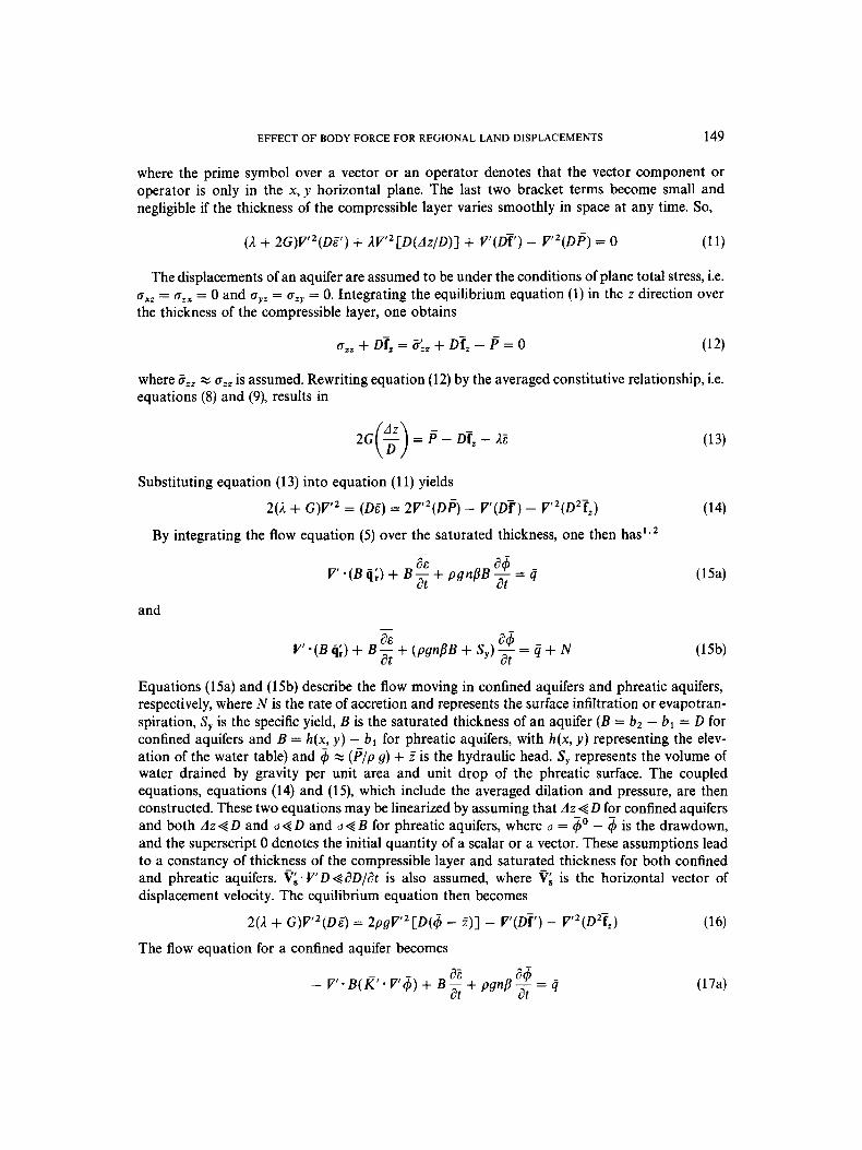
results are drawn in Figures 3 and 4. The relationship of the drawdown, horizontal displacement and vertical displacement versus the distance from the well after continuous pumping for 3 yrs is shown in Figure 3. The relationship of the drawdown, horizontal displacement and vertical displacement versus time at a distance of 3 km from the pumping well is shown in Figure 4. The horizontal displacement can be observed from Figure 3 to have a maximum value of 2.16 cm at a distance of approximately 1.7 km from the pumping well. The magnitude of the horizontal displacement is of one order of magnitude or more greater than that of the vertical displacement beyond a distance of 1.9 km from the well. The influence range of the vertical displacement in a phreatic aquifer is smaller than that in a confined aquifer. Both vertical and horizontal displacements can be observed from Figure 4 to increase with time if the well is pumped continuously. Comparisons of the drawdowns, vertical displacements and horizontal displace- ments of confined and phreatic aquifers at a distance of 50 m from the pumping well are drawn in Figures 5, 6 and 7, respectively. Both horizontal and vertical displacements in the phreatic case can be seen to be smaller than those occurring in the confined case. Results by Corapcioglu and Bear2 are also drawn in Figures 3-7. Their results, indicated by dashed lines in Figures 3-7, are slightly larger than our results in the case of the phreatic aquifer. These discrepancies are the result of errors made in their equations (74), (74), (82) and (86).
Pumping Time (hours) Figure 6. Comparison of the vertical displacements for pumping in confined and phreatic aquifers at a distance of 50 m
from the pumping well
158 RUEY-HSING LU AND HUND-DER YEH
__ Lu & Yeh _ _ Corapcloglu & Bear
Figure 7. Comparison of the horizontal displacements for pumping in confined and phreatic aquifers at a distance of 50 m from the pumping well
SUMMARY AND CONCLUSIONS
The coupled equations presented in this investigation take into consideration the effect of the body force in the equilibrium equation of stress field. An elastic constitutive relationship between the effective stress and the displacement was introduced in order to couple the equilibrium and flow equations. These equations were integrated over the vertical thickness of the aquifers. Assumptions made in the derivation include (1) no external force acting on the top and bottom bounding boundaries of the compressible layer exists and (2) the horizontal displacements have no variations along the vertical direction. The concept of plane total stress was also employed in this study. Two regional equations coupling the averaged dilation and pressure were then obtained. Since the integrated effect of the body force was considered in this approach, fewer assumptions were necessary and the procedures were less complicated than those of Bear and Corapcioglu,1*2 especially in the case of phreatic aquifers. The pumping data sets provided in the papers of Bear and Corapcioglu'p2 in 1981 and 1983, respectively, were analysed as simple case studies. The drawdown and displacements in a confined aquifer were demonstrated to be the same as the results presented by Bear and Corapcioglu.' In a phreatic aquifer, however, the results estimated by the proposed approach were slightly different from those of Corapcioglu and Bear.2 Some equations in Corapcioglu and Bear2 could possibly have been incorrect.

EFFECT OF BODY FORCE FOR REGIONAL LAND DISPLACEMENTS 159
The horizontal displacement and vertical displacement in a phreatic aquifer can be observed from Figures 1-7 to be smaller than those in a confined aquifer. The influence range of the vertical displacement in a phreatic aquifer was also smaller than that in a confined aquifer. The horizontal displacement, which has been neglected by some researchers, was found to be quite significant and should not be neglected. For both confined and phreatic aquifers, the magnitude of the horizontal displacement was generally found to be almost one order of magnitude or more greater than that of the vcrtical displacement at distances beyond several kilometres from the pumping well. It is interesting to note that the mechanisms of displacements in the confined and phreatic aquifers are not the same. Displacements occurring in confined aquifers are induced by the pressure decline only. On the other hand, displacements occurring in phreatic aquifers are caused by the drop of the water table and the change in body force. Displacement behaviour in a phreatic aquifer, however, will appear similar to that in a confined aquifer if the change of the body force is neglected. Therefore, it is suggested that the change of the body force should be considered when phreatic aquifers are pumped.
ACKNOWLEDGEMENT
This work was supported by the National Science Council of the Republic of China, under grant NSC 79-0410-E009-2 1. The authors would like to thank three anonymous reviewers for their valuable and constructive comments.
REFERENCES
1. J. Bear and M. Y . Corapcioglu, ‘Mathematical model for regional land subsidence due to pumping, 2. Integrated aquifer subsidence equations for vertical and horizontal displacements’, Water Resour. Res., 17, 947-958 (1981).
2. M. Y. Corapcioglu and J. Bear, ‘A mathematical model for regional land subsidence due to pumping, 3. Integrated equations for a phreatic aquifer’, Water Resour. Res., 19, 895-908 (1983).
3. M. Y . Corapcioglu, ‘Land subsidence-A. A state-of-the-art review’, in J. Bear and M. Y. Corapcioglu (eds), Fundamentals of Transport Phenomena in Porous Media, Martinus Nijhoff, Dordrecht, 1984, pp. 369444.
4. K. Terzaghi, Erdbaumechanik auf bodenphysikalischer Grundlage, Franz Deuticke, Vienna, 1925. 5. R. E. Miller, ‘Compaction of an artesian aquifer system computed from consolidation tests and decline in artesian
6. H. Bouwer, ‘Land subsidence and cracking due to ground-water depletion’, Groundwater, 15, 358-364 (1977). 7. C. Zeevaert, Foundation Engineeringfor Dificult Subsoil Conditions, Van Nostrand, New York, 1977, pp. 245-281. 8. J. F. Schatz, P. W. Kasameyer and J. A. Cheney, ‘A method of using in situ porosity measurements to place an upper
bound on geothermal reservoir compaction’, Proc. 2nd Invitational well Testing Symp., Lawrence Berkeley Laborat- ory, Berkeley, 1978, pp. W 9 4 .
9. B. E. Lofgren and R. L. Klausing, ‘Land subsidence due to groundwater withdrawal, Tulare-Wasco area, California’, U S . Geol. Survey Prof. Paper 437-8, 1969.
10. R. K. Gabrysch and C. W. Bonnet, ‘Land-surface subsidence at Seabrook, Texas’, U.S. Geol. Survey Open File Report, 1975, pp. 75413.
1 1 . G. Gambolati, G. Ricceri, W. Bertoni, G. Brighteni and E. Vuillermin, ‘Mathematical simulation of the subsidence of Ravenna’, Water Resour. Res., 21, 2899-2918 (1991).
12. R. W. Lewis and B. A. Schrefler, The Finite Element Method in the Deformation and Consolidation of Porous Media, W i k y , New York, 1987.
13. N. Carrillo, Subsidence in the Long Beach-San Pedro Area, Stanford Research Institute, Stanford, 1949, pp. 65-77,
14. G. D. McCann and C. H. Wilts, A Mathematical Analysis of the Subsidence in the Long Beach-San Pedro Area,
15. J. Geertsma, ‘Problems of rock mechanics in petroleum production engineering’, Proc. 1st Cong. Int. Soc. Rock Mech.,
16. J. Geertsma, ‘Land subsidence above compacting oil and gas reservoirs’, J . Pet. Tech., 25, 734-744 (1973). 17. M. A. Biot, ‘General theory of three-dimensional consolidation’, J . Appl. Phys., 12, 155-164 (1941). 18. M. A. Biot, ‘Theory of elasticity and consolidation for a porous anisotropic solid‘, J . Appl. Phys., 26, 182-185 (1955). 19. P. A. Domenico and M. D. Mifflin, ‘Water from low permeability sediments and land subsidence’, Water Resour. Res.,
field,’, U.S. Geol. Survey Prof: Paper 424-B, vol. 26, 1961, pp. B54B58.
225-243.
Pasadena, Internal Report, California Institute of Technology, 1951.
Lisbon, Vol. 1, 1966, pp. 585-594.
1, 563-576 (1965).

160 RUEY-HSING LU AND HUND-DER YEH
20. G. Gambolati and R. A. Freeze, ‘Mathematical simulation of the subsidence of Venice, 1. Theory’, Water Resour. Res.,
21. N. M. Safai and G. F. Pinder, ‘Vertical and horizontal land deformation in a desaturating porous medium’, Adu.
22. N. M. Safai and G. F. Pinder, ‘Vertical and horizontal land deformation due to fluid withdrawal’, Int. j . numer. anal.
23. D. W. Taylor and W. Merchant, ‘A theory of clay consolidation accounting for secondary compression’, J . Math.
24. M. Y. Corapcioglu, ‘Mathematical modelling of leaky aquifers with rheological properties’, Proc. 2nd Int. Symp. on
25. M. Y. Corapcioglu and W. Brutsaert, ‘Viscoelastic aquifer model applied to subsidence due to pumping’, Water
26. M. Kojic and J. B. Cheatham, Jr., ‘Theory of plasticity of porous media with fluid flow’, SOC. Pet. Eng. J., 14,263-270
27. 0. C. Zienkiewicz and I. C. Cormeau, ‘Viscoplasticity -- plasticity and creep in elastic solids - a unified numerical
28. R. W. Lewis, B. A. Schrefler and L. Simoni, ‘Coupling versus uncoupling in soil consolidation’, Int. j. numer. anal.
29. A. Verruijt, ‘Horizontal displacements in pumped aquifers’ (abstract), EOS Trans. Amer. Geophys. Union, 51, 204
30. A. Debbarh, ‘Consolidation of elastic saturated soil due to water withdrawal by numerical Laplace-Fourier inversion
31. G. Gambolati, ‘Comment on coupling versus uncoupling in soil consolidation’, In t . j. numer. anal. methods geomech.,
32. J. Bear and Y. Bachmat, Introduction to Modeling of Transport Phenomena in Porous Media, Kluwer, Boston, 1990. 33. A. Verruijt, Theory of Groundwater Flow, 2nd edn, Macmillan, London, 1982. 34. A. Verruijt, ‘Elastic storage of aquifers’, in R. J. M. Dewiest (ed.), Flow Through Porous Media, Academic Press, New
35. J. Bear and M. Y. Corapcioglu, ‘Centrifugal filtration in deformable porous media’, in Water Flow in Deformable
36. J. Bear and M. Y. Corapcioglu, ‘Mathematical model for regional land subsidence due to pumping, 1. Integrated
9, 721-733 (1973).
Water Resour., 2, 19-25 (1979).
methods geomech., 4, 131-142 (1980).
Phys., 19, 167-185 (1940).
Land Subsidence, Anaheim, Calif: Int. Assoc. of Hydrological Sciences Pub. No. 121, 1977, pp. 191-200.
Resour. Res., 13, 597-604 (1977).
(1974).
solution approach’, Int. j. numer. methods eng., 8, 821-845 (1974).
methods geomech., 15, 533-548 (1991).
(1970).
methods’, Ph.D. Thesis, Dept. of Civ. and Min. Eng., Univ. of Minn., Minneapolis, 1988.
16,833-837 (1992).
York, 1969, pp. 331-376.
Porous Media, Report, Dept. of Civ. Eng., Univ. of Mich., Ann Arbor, 1981.
aquifer subsidence equations based on vertical displacement only’, Water Resour. Res., 17, 937-946 (1981).