CONSIDERATIONS FOR LOW SULFUR COAL BLENDING AT … · Considerations for Low Sulfur Coal Blending...
18
Considerations for Low Sulfur Coal Blending Page 1 of 18 at B. L. England Station CONSIDERATIONS FOR LOW SULFUR COAL BLENDING AT B. L. ENGLAND STATION J. M. Russell M. B. Gillespie, P.E. MPR Associates, Inc., 320 King Street, Alexandria, VA 22314-323 W. C. Gibson V. N. Bhamidipati Conectiv, B. L. England Station, 900 North Shore Road, Beesley’s Point, NJ 08223 D. Mahr, P.E. Energy Associates, P.C., 150 River Road, Suite J4, Montville, NJ 07045 Abstract On-site blending of coal to produce an economical, lower sulfur fuel is one compliance approach to SO 2 emissions regulation. At existing generating stations, implementation of on-site blending has a major impact on the coal stockpile arrangement and equipment required to unload, store, reclaim, blend, and deliver fuel to the boiler. The on-site coal blending system for B. L. England Station must produce a blended coal that satisfies (1) environmental limits on sulfur emissions, (2) operational limits on ash fusion temperatures, slagging, and heat content, and (3) limitations of a non-redundant fuel supply system. At B. L. England Station, the design and operating concerns are complicated by the need to supply different fuels to the two cyclone-fired units. Unit 2 is equipped with a wet flue gas desulphurization system that does not require the same low sulfur coal as Unit 1. This paper describes the factors that control the implementation of an on-site coal blending facility at the B. L. England Station. The features of the existing coal stockpile and handling system arrangement that impact the blending alternatives are also discussed. The paper details the evaluations performed to compare the blending control options, including coal storage, on- line fuel analysis and mass-based blending. In addition, the approach used to incorporate the existing equipment and control system at B. L. England Station to reliably produce a consistent, controlled coal blend is described. Finally, the paper provides a comparison of the estimated costs and schedules required to implement the on-site coal blending alternatives. Background Atlantic City Electric (ACE) operates two similar coal fired, cyclone boilers at the B. L. England Station, located in Beesley’s Point, New Jersey. The B. L. England Station Unit 1 (BLE-1) and Unit 2 (BLE-2) boilers, which were designed by Babcock and Wilcox in the 1960’s, are both equipped with electrostatic precipitators to control particulate emissions. BLE-2 is also equipped with a wet flue gas desulphurization system designed by General Electric to control SO 2 emissions from the unit. Both units were retrofit with Nalco NO X OUT selective non-catalytic reduction (SNCR) systems in the mid-1990’s and over-fire air systems in the late 1990’s to comply with the requirements to control NO X emissions during the ozone season. The design characteristics of the coal-fired units at B. L. England Station are listed in Table 1.
-
Upload
duongkhuong -
Category
Documents
-
view
226 -
download
1
Transcript of CONSIDERATIONS FOR LOW SULFUR COAL BLENDING AT … · Considerations for Low Sulfur Coal Blending...

Considerations for Low Sulfur Coal Blending Page 1 of 18at B. L. England Station
CONSIDERATIONS FOR LOW SULFUR COAL BLENDINGAT B. L. ENGLAND STATION
J. M. RussellM. B. Gillespie, P.E.
MPR Associates, Inc., 320 King Street, Alexandria, VA 22314-323W. C. Gibson
V. N. BhamidipatiConectiv, B. L. England Station, 900 North Shore Road, Beesley’s Point, NJ 08223
D. Mahr, P.E.Energy Associates, P.C., 150 River Road, Suite J4, Montville, NJ 07045
Abstract
On-site blending of coal to produce an economical, lower sulfur fuel is one compliance approachto SO2 emissions regulation. At existing generating stations, implementation of on-site blendinghas a major impact on the coal stockpile arrangement and equipment required to unload, store,reclaim, blend, and deliver fuel to the boiler. The on-site coal blending system for B. L. EnglandStation must produce a blended coal that satisfies (1) environmental limits on sulfur emissions,(2) operational limits on ash fusion temperatures, slagging, and heat content, and (3) limitationsof a non-redundant fuel supply system. At B. L. England Station, the design and operatingconcerns are complicated by the need to supply different fuels to the two cyclone-fired units.Unit 2 is equipped with a wet flue gas desulphurization system that does not require the samelow sulfur coal as Unit 1.
This paper describes the factors that control the implementation of an on-site coal blendingfacility at the B. L. England Station. The features of the existing coal stockpile and handlingsystem arrangement that impact the blending alternatives are also discussed. The paper detailsthe evaluations performed to compare the blending control options, including coal storage, on-line fuel analysis and mass-based blending. In addition, the approach used to incorporate theexisting equipment and control system at B. L. England Station to reliably produce a consistent,controlled coal blend is described. Finally, the paper provides a comparison of the estimatedcosts and schedules required to implement the on-site coal blending alternatives.
Background
Atlantic City Electric (ACE) operates two similar coal fired, cyclone boilers at the B. L. EnglandStation, located in Beesley’s Point, New Jersey. The B. L. England Station Unit 1 (BLE-1) andUnit 2 (BLE-2) boilers, which were designed by Babcock and Wilcox in the 1960’s, are bothequipped with electrostatic precipitators to control particulate emissions. BLE-2 is also equippedwith a wet flue gas desulphurization system designed by General Electric to control SO2
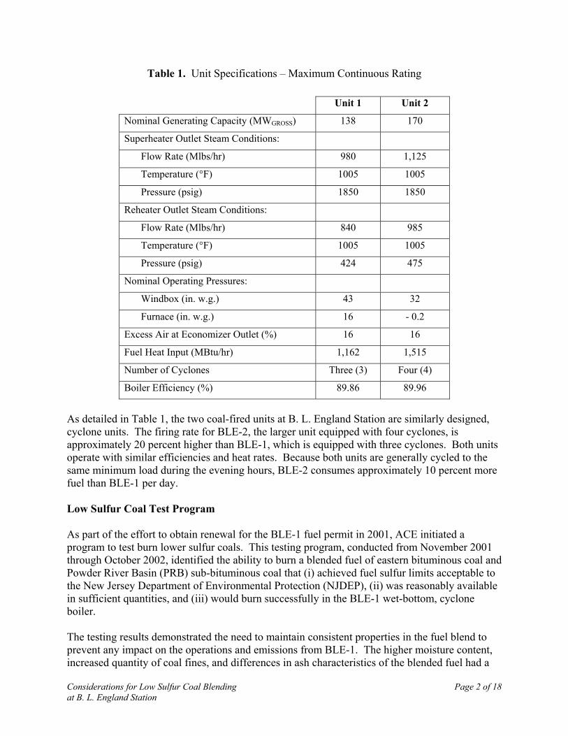
emissions from the unit. Both units were retrofit with Nalco NOXOUT selective non-catalyticreduction (SNCR) systems in the mid-1990’s and over-fire air systems in the late 1990’s tocomply with the requirements to control NOX emissions during the ozone season. The designcharacteristics of the coal-fired units at B. L. England Station are listed in Table 1.
Considerations for Low Sulfur Coal Blending Page 2 of 18at B. L. England Station
Table 1. Unit Specifications – Maximum Continuous Rating
Unit 1 Unit 2
Nominal Generating Capacity (MWGROSS) 138 170
Superheater Outlet Steam Conditions:
Flow Rate (Mlbs/hr) 980 1,125
Temperature (°F) 1005 1005
Pressure (psig) 1850 1850
Reheater Outlet Steam Conditions:
Flow Rate (Mlbs/hr) 840 985
Temperature (°F) 1005 1005
Pressure (psig) 424 475
Nominal Operating Pressures:
Windbox (in. w.g.) 43 32
Furnace (in. w.g.) 16 - 0.2
Excess Air at Economizer Outlet (%) 16 16
Fuel Heat Input (MBtu/hr) 1,162 1,515
Number of Cyclones Three (3) Four (4)
Boiler Efficiency (%) 89.86 89.96
As detailed in Table 1, the two coal-fired units at B. L. England Station are similarly designed,cyclone units. The firing rate for BLE-2, the larger unit equipped with four cyclones, isapproximately 20 percent higher than BLE-1, which is equipped with three cyclones. Both unitsoperate with similar efficiencies and heat rates. Because both units are generally cycled to thesame minimum load during the evening hours, BLE-2 consumes approximately 10 percent morefuel than BLE-1 per day.
Low Sulfur Coal Test Program
As part of the effort to obtain renewal for the BLE-1 fuel permit in 2001, ACE initiated aprogram to test burn lower sulfur coals. This testing program, conducted from November 2001through October 2002, identified the ability to burn a blended fuel of eastern bituminous coal andPowder River Basin (PRB) sub-bituminous coal that (i) achieved fuel sulfur limits acceptable tothe New Jersey Department of Environmental Protection (NJDEP), (ii) was reasonably availablein sufficient quantities, and (iii) would burn successfully in the BLE-1 wet-bottom, cycloneboiler.
The testing results demonstrated the need to maintain consistent properties in the fuel blend toprevent any impact on the operations and emissions from BLE-1. The higher moisture content,increased quantity of coal fines, and differences in ash characteristics of the blended fuel had a
Considerations for Low Sulfur Coal Blending Page 3 of 18at B. L. England Station
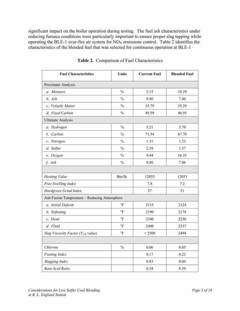
significant impact on the boiler operation during testing. The fuel ash characteristics underreducing furnace conditions were particularly important to ensure proper slag tapping whileoperating the BLE-1 over-fire air system for NOX emissions control. Table 2 identifies thecharacteristics of the blended fuel that was selected for continuous operation at BLE-1
Table 2. Comparison of Fuel Characteristics
Fuel Characteristics Units Current Fuel Blended Fuel
Proximate Analysis
a. Moisture % 5.15 10.29
b. Ash % 9.80 7.46
c. Volatile Matter % 35.79 35.29
d. Fixed Carbon % 49.59 46.95
Ultimate Analysis
a. Hydrogen % 5.21 5.70
b. Carbon % 71.54 67.70
c. Nitrogen % 1.31 1.23
d. Sulfur % 2.39 1.57
e. Oxygen % 9.44 16.35
f. Ash % 9.80 7.46
Heating Value Btu/lb. 12855 12053
Free Swelling Index 7.8 7.2
Hardgrove Grind Index 57 51
Ash Fusion Temperature – Reducing Atmosphere
a. Initial Deform oF 2115 2124
b. Softening oF 2190 2178
c. Hemi oF 2340 2236
d. Fluid oF 2400 2337
Slag Viscosity Factor (T250 value) oF > 2500 2494
Chlorine % 0.06 0.05
Fouling Index 0.17 0.22
Slagging Index 0.83 0.60
Base/Acid Ratio 0.34 0.39
Considerations for Low Sulfur Coal Blending Page 4 of 18at B. L. England Station
The blended fuel permitted for use in BLE-1 was limited to 30 percent PRB. This blendprovided the necessary regulatory improvement in sulfur emissions without adversely impactingunit operations. Fuel blends with a higher percentage of PRB coal would have requiredextensive modification to the boiler and electrostatic precipitators that were not part of the fuelpermit renewal process.
During the low sulfur coal test program, the coal was blended at an off-site facility in sufficientquantities to support BLE-1 operation for a 30-day test burn. The off-site blending involvedunloading the PRB coal at an intermediate trans-shipping facility and then layer-loading the PRBcoal into a second train whose cars were partially loaded with the contract coal (i.e., easternbituminous coal). This method of blending resulted in some unacceptable variations in the fired-fuel properties. The additional fuel handling and transportation also increased the cost of thisalternative. Table 3 compares the cost of the fuel for BLE-1 between on-site blending and off-site blending.
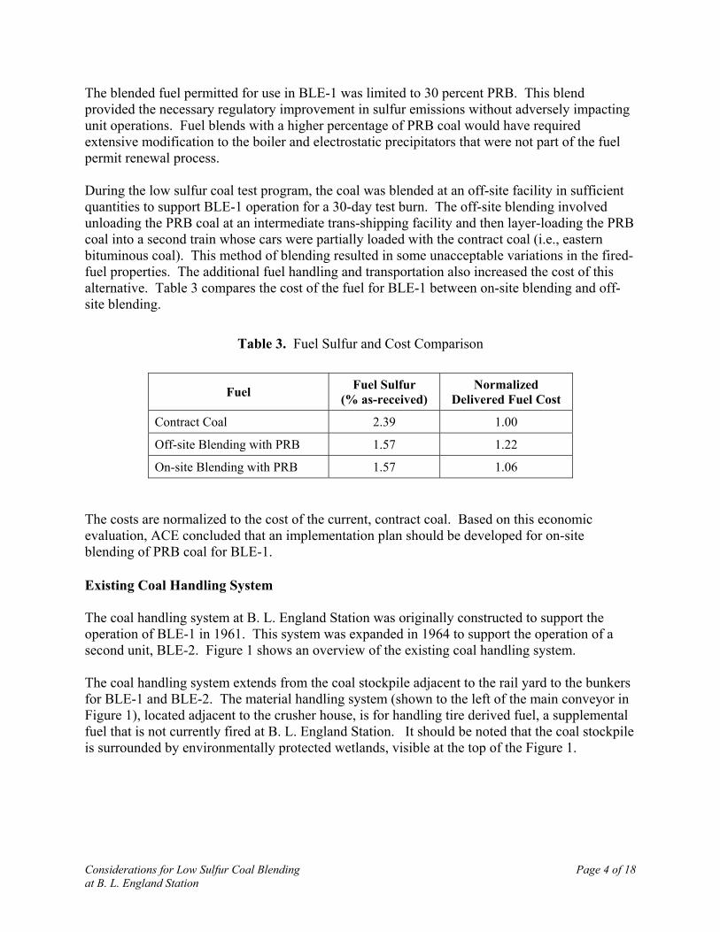
Table 3. Fuel Sulfur and Cost Comparison
Fuel Fuel Sulfur(% as-received)
NormalizedDelivered Fuel Cost
Contract Coal 2.39 1.00
Off-site Blending with PRB 1.57 1.22
On-site Blending with PRB 1.57 1.06
The costs are normalized to the cost of the current, contract coal. Based on this economicevaluation, ACE concluded that an implementation plan should be developed for on-siteblending of PRB coal for BLE-1.
Existing Coal Handling System
The coal handling system at B. L. England Station was originally constructed to support theoperation of BLE-1 in 1961. This system was expanded in 1964 to support the operation of asecond unit, BLE-2. Figure 1 shows an overview of the existing coal handling system.
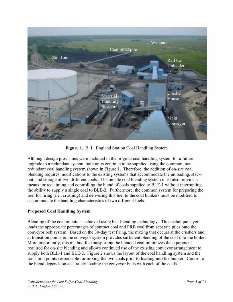
The coal handling system extends from the coal stockpile adjacent to the rail yard to the bunkersfor BLE-1 and BLE-2. The material handling system (shown to the left of the main conveyor inFigure 1), located adjacent to the crusher house, is for handling tire derived fuel, a supplementalfuel that is not currently fired at B. L. England Station. It should be noted that the coal stockpileis surrounded by environmentally protected wetlands, visible at the top of the Figure 1.
Considerations for Low Sulfur Coal Blending Page 5 of 18at B. L. England Station
Figure 1. B. L. England Station Coal Handling System
Although design provisions were included in the original coal handling system for a futureupgrade to a redundant system, both units continue to be supplied using the common, non-redundant coal handling system shown in Figure 1. Therefore, the addition of on-site coalblending requires modifications to the existing systems that accommodate the unloading, stack-out, and storage of two different coals. The on-site coal blending system must also provide ameans for reclaiming and controlling the blend of coals supplied to BLE-1 without interruptingthe ability to supply a single coal to BLE-2. Furthermore, the common system for preparing thefuel for firing (i.e., crushing) and delivering this fuel to the coal bunkers must be modified toaccommodate the handling characteristics of two different fuels.
Proposed Coal Handling System
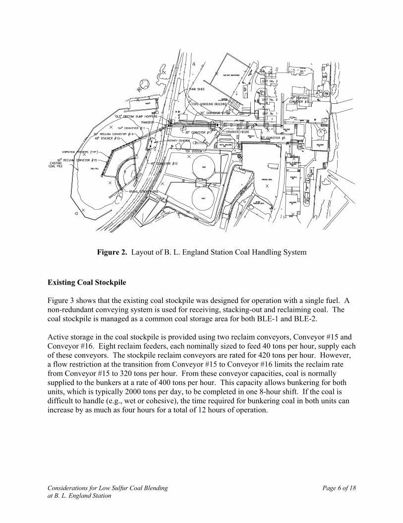
Blending of the coal on-site is achieved using bed-blending technology. This technique layerloads the appropriate percentages of contract coal and PRB coal from separate piles onto theconveyor belt system. Based on the 30-day test firing, the mixing that occurs at the crushers andat transition points in the conveyor system provides sufficient blending of the coal into the boiler.More importantly, this method for transporting the blended coal minimizes the equipmentrequired for on-site blending and allows continued use of the existing conveyor arrangement tosupply both BLE-1 and BLE-2. Figure 2 shows the layout of the coal handling system and thetransition points responsible for mixing the two coals prior to loading into the bunker. Control ofthe blend depends on accurately loading the conveyor belts with each of the coals.
Coal Stockpile
Rail Line Rail CarUnloader
MaterialHandlingSystem
CrusherHouse
MainConveyor
Wetlands
Considerations for Low Sulfur Coal Blending Page 6 of 18at B. L. England Station
Figure 2. Layout of B. L. England Station Coal Handling System
Existing Coal Stockpile
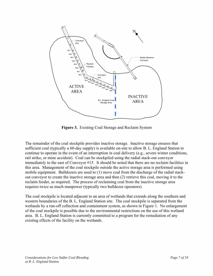
Figure 3 shows that the existing coal stockpile was designed for operation with a single fuel. Anon-redundant conveying system is used for receiving, stacking-out and reclaiming coal. Thecoal stockpile is managed as a common coal storage area for both BLE-1 and BLE-2.
Active storage in the coal stockpile is provided using two reclaim conveyors, Conveyor #15 andConveyor #16. Eight reclaim feeders, each nominally sized to feed 40 tons per hour, supply eachof these conveyors. The stockpile reclaim conveyors are rated for 420 tons per hour. However,a flow restriction at the transition from Conveyor #15 to Conveyor #16 limits the reclaim ratefrom Conveyor #15 to 320 tons per hour. From these conveyor capacities, coal is normallysupplied to the bunkers at a rate of 400 tons per hour. This capacity allows bunkering for bothunits, which is typically 2000 tons per day, to be completed in one 8-hour shift. If the coal isdifficult to handle (e.g., wet or cohesive), the time required for bunkering coal in both units canincrease by as much as four hours for a total of 12 hours of operation.
Considerations for Low Sulfur Coal Blending Page 7 of 18at B. L. England Station
B.L. England CoalStorage Area
16-1
16-2
16-3
16-4
16-5
16-6
16-7
16-8
15-4
15-115-2
15-3
15-515-6
15-715-8
Radial StackoutConveyor
Conveyor#16
Conveyor#15
ReclaimFeeders
Figure 3. Existing Coal Storage and Reclaim System
The remainder of the coal stockpile provides inactive storage. Inactive storage ensures thatsufficient coal (typically a 60-day supply) is available on-site to allow B. L. England Station tocontinue to operate in the event of an interruption in coal delivery (e.g., severe winter conditions,rail strike, or mine accident). Coal can be stockpiled using the radial stack-out conveyorimmediately to the east of Conveyor #15. It should be noted that there are no reclaim facilities inthis area. Management of the coal stockpile outside the active storage area is performed usingmobile equipment. Bulldozers are used to (1) move coal from the discharge of the radial stack-out conveyor to create the inactive storage area and then (2) retrieve this coal, moving it to thereclaim feeder, as required. The process of reclaiming coal from the inactive storage arearequires twice as much manpower (typically two bulldozer operators).
The coal stockpile is located adjacent to an area of wetlands that extends along the southern andwestern boundaries of the B. L. England Station site. The coal stockpile is separated from thewetlands by a run-off collection and containment system, as shown in Figure 1. No enlargementof the coal stockpile is possible due to the environmental restrictions on the use of this wetlandarea. B. L. England Station is currently committed to a program for the remediation of anyexisting effects of the facility on the wetlands.
ACTIVEAREA
INACTIVEAREA
N
Considerations for Low Sulfur Coal Blending Page 8 of 18at B. L. England Station
New Coal Stockpile
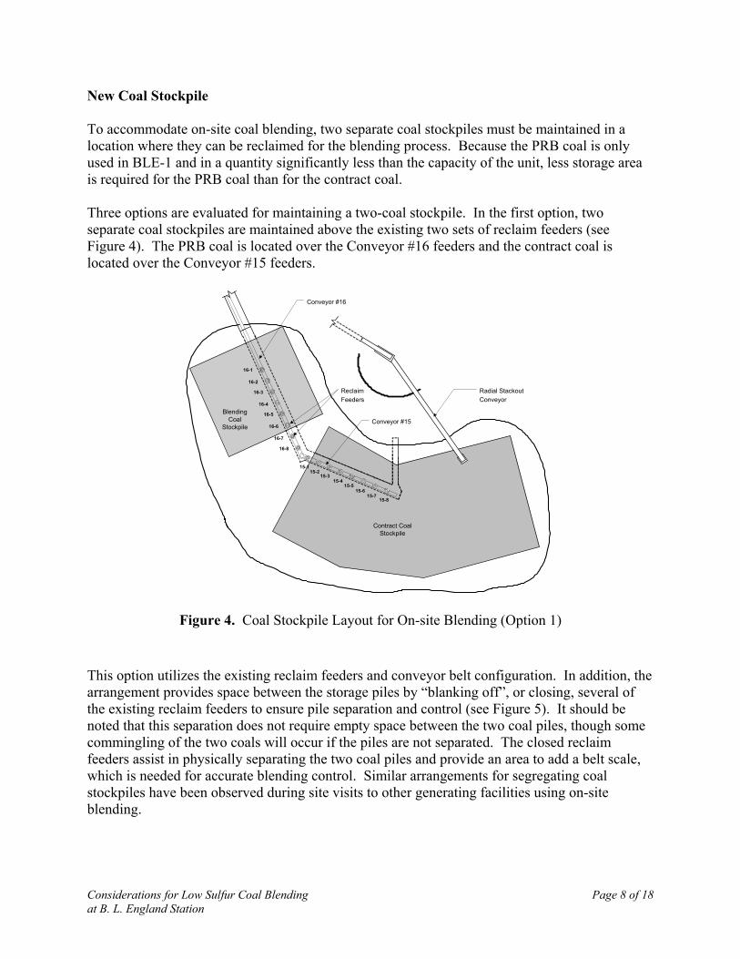
To accommodate on-site coal blending, two separate coal stockpiles must be maintained in alocation where they can be reclaimed for the blending process. Because the PRB coal is onlyused in BLE-1 and in a quantity significantly less than the capacity of the unit, less storage areais required for the PRB coal than for the contract coal.
Three options are evaluated for maintaining a two-coal stockpile. In the first option, twoseparate coal stockpiles are maintained above the existing two sets of reclaim feeders (seeFigure 4). The PRB coal is located over the Conveyor #16 feeders and the contract coal islocated over the Conveyor #15 feeders.
BlendingCoal
Stockpile
16-1
16-2
16-3
16-4
16-5
16-6
16-7
16-8
Contract CoalStockpile
15-4
15-115-2
15-3
15-515-6
15-715-8
Radial StackoutConveyor
Conveyor #16
Conveyor #15
ReclaimFeeders
Figure 4. Coal Stockpile Layout for On-site Blending (Option 1)
This option utilizes the existing reclaim feeders and conveyor belt configuration. In addition, thearrangement provides space between the storage piles by “blanking off”, or closing, several ofthe existing reclaim feeders to ensure pile separation and control (see Figure 5). It should benoted that this separation does not require empty space between the two coal piles, though somecommingling of the two coals will occur if the piles are not separated. The closed reclaimfeeders assist in physically separating the two coal piles and provide an area to add a belt scale,which is needed for accurate blending control. Similar arrangements for segregating coalstockpiles have been observed during site visits to other generating facilities using on-siteblending.

Considerations for Low Sulfur Coal Blending Page 9 of 18at B. L. England Station
Conveyor #16 Conveyor #15
25'25'
Blending CoalContract
Coal
Two Roller Belt ScaleLocation
Convex Curve
Operating FeedPoint
Contract CoalCoal Blend
Blanked ReclaimFeeders
Figure 5. Separation of Adjacent Coal Piles (Option 1)
The second option incorporates a retaining wall to separate the two coal piles, which indirectlyincreases the coal stockpile storage capacity. While this arrangement marginally increases thestorage capacity (i.e., 21 percent more PRB coal storage and nine percent more contract coalstorage), it provides a more controlled and definitive separation of the two different coals (seeFigure 6). However, this option involves substantial construction expense and schedulingdifficulties to provide uninterrupted fuel supply to the B. L. England Station units during theconstruction of the retaining wall.
PRB CoalPile
16-1
16-2
16-3
16-4
16-5
16-6
16-7
16-8
BituminousCoal Pile
15-4
15-115-2
15-3
15-515-6
15-715-8
Radial StackoutConveyor
Conveyor #16
Conveyor #15
ReclaimFeeders
Concrete Wall
Figure 6. Coal Stockpile Layout for On-site Blending (Option 2)
Considerations for Low Sulfur Coal Blending Page 10 of 18at B. L. England Station
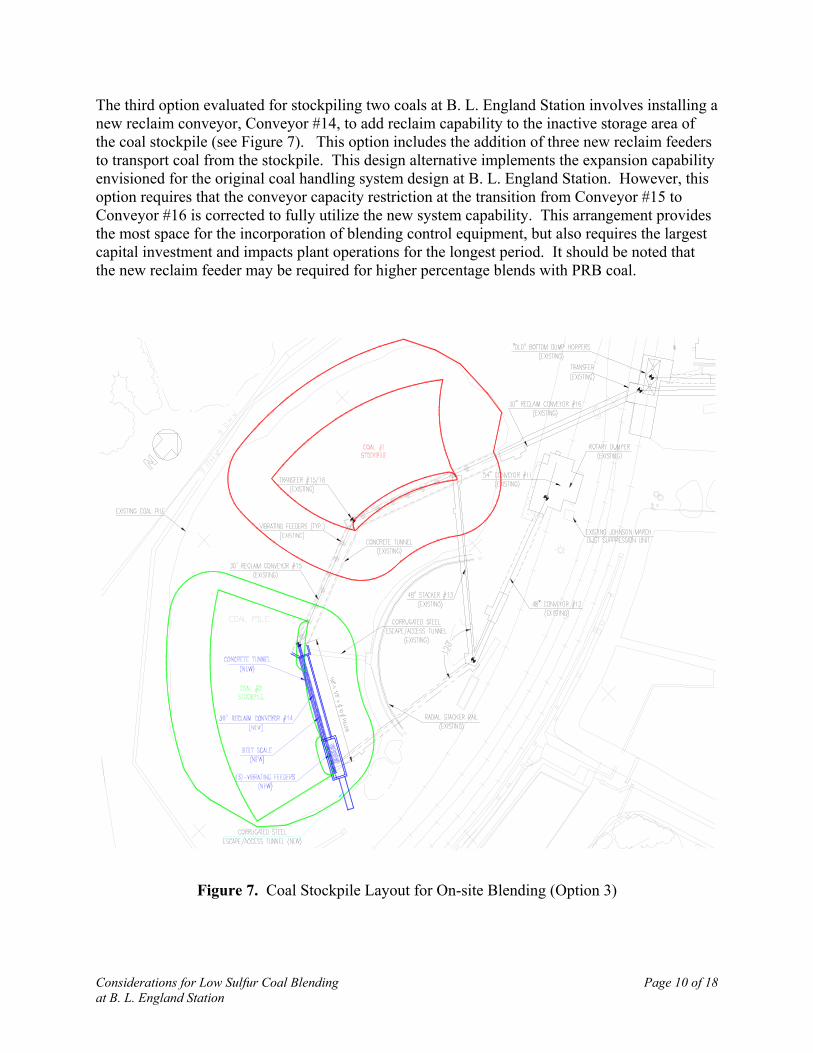
The third option evaluated for stockpiling two coals at B. L. England Station involves installing anew reclaim conveyor, Conveyor #14, to add reclaim capability to the inactive storage area ofthe coal stockpile (see Figure 7). This option includes the addition of three new reclaim feedersto transport coal from the stockpile. This design alternative implements the expansion capabilityenvisioned for the original coal handling system design at B. L. England Station. However, thisoption requires that the conveyor capacity restriction at the transition from Conveyor #15 toConveyor #16 is corrected to fully utilize the new system capability. This arrangement providesthe most space for the incorporation of blending control equipment, but also requires the largestcapital investment and impacts plant operations for the longest period. It should be noted thatthe new reclaim feeder may be required for higher percentage blends with PRB coal.
Figure 7. Coal Stockpile Layout for On-site Blending (Option 3)
Considerations for Low Sulfur Coal Blending Page 11 of 18at B. L. England Station
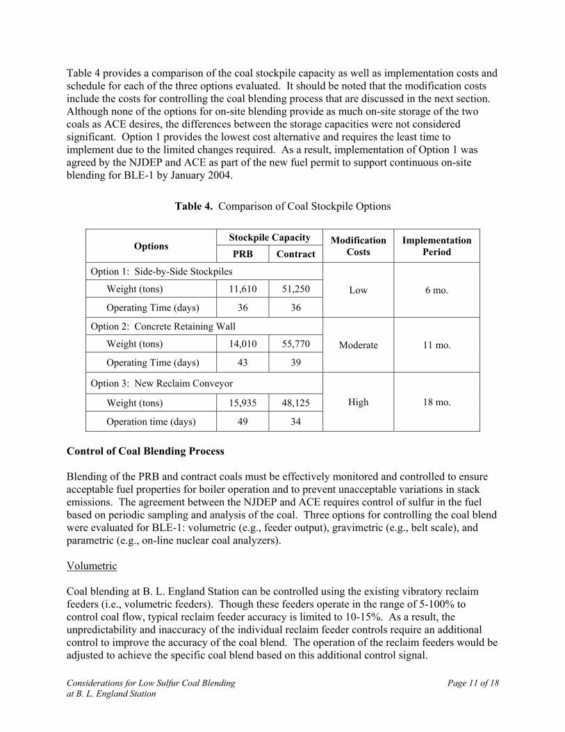
Table 4 provides a comparison of the coal stockpile capacity as well as implementation costs andschedule for each of the three options evaluated. It should be noted that the modification costsinclude the costs for controlling the coal blending process that are discussed in the next section.Although none of the options for on-site blending provide as much on-site storage of the twocoals as ACE desires, the differences between the storage capacities were not consideredsignificant. Option 1 provides the lowest cost alternative and requires the least time toimplement due to the limited changes required. As a result, implementation of Option 1 wasagreed by the NJDEP and ACE as part of the new fuel permit to support continuous on-siteblending for BLE-1 by January 2004.
Table 4. Comparison of Coal Stockpile Options
Stockpile CapacityOptions
PRB ContractModification
CostsImplementation
Period
Option 1: Side-by-Side Stockpiles
Weight (tons) 11,610 51,250
Operating Time (days) 36 36
Low 6 mo.
Option 2: Concrete Retaining Wall
Weight (tons) 14,010 55,770
Operating Time (days) 43 39
Moderate 11 mo.
Option 3: New Reclaim Conveyor
Weight (tons) 15,935 48,125
Operation time (days) 49 34
High 18 mo.
Control of Coal Blending Process
Blending of the PRB and contract coals must be effectively monitored and controlled to ensureacceptable fuel properties for boiler operation and to prevent unacceptable variations in stackemissions. The agreement between the NJDEP and ACE requires control of sulfur in the fuelbased on periodic sampling and analysis of the coal. Three options for controlling the coal blendwere evaluated for BLE-1: volumetric (e.g., feeder output), gravimetric (e.g., belt scale), andparametric (e.g., on-line nuclear coal analyzers).
Volumetric
Coal blending at B. L. England Station can be controlled using the existing vibratory reclaimfeeders (i.e., volumetric feeders). Though these feeders operate in the range of 5-100% tocontrol coal flow, typical reclaim feeder accuracy is limited to 10-15%. As a result, theunpredictability and inaccuracy of the individual reclaim feeder controls require an additionalcontrol to improve the accuracy of the coal blend. The operation of the reclaim feeders would beadjusted to achieve the specific coal blend based on this additional control signal.
Considerations for Low Sulfur Coal Blending Page 12 of 18at B. L. England Station
Gravimetric
The existing coal handling system uses a four-idler belt scale (Scale #1) on Conveyor #17 (seeFigure 2) to measure the total coal flow to the bunkers. This scale provides a measurementaccuracy of one percent. To control the ratio of coals in the blend gravimetrically, an additionalbelt scale (Scale #2) is necessary in the reclaim system to provide information about only one ofthe coals. Based on the selected coal stockpiling alternative (Option 1), the appropriate locationfor an additional scale is either at the end of Conveyor #15 or the beginning of Conveyor #16(i.e., between the reclaim feed points of the contract coal and PRB coal). A scale at this locationprovides a measurement of the contract coal alone. The amount of PRB coal supplied for theblend is controlled based on the difference of the measured weight of contract coal (Scale #2)and the total weight of the blend (Scale #1). The reclaim feeders on Conveyor #16 are thencontrolled based on the signal provided by the existing belt scale on Conveyor #17 (Scale #1).
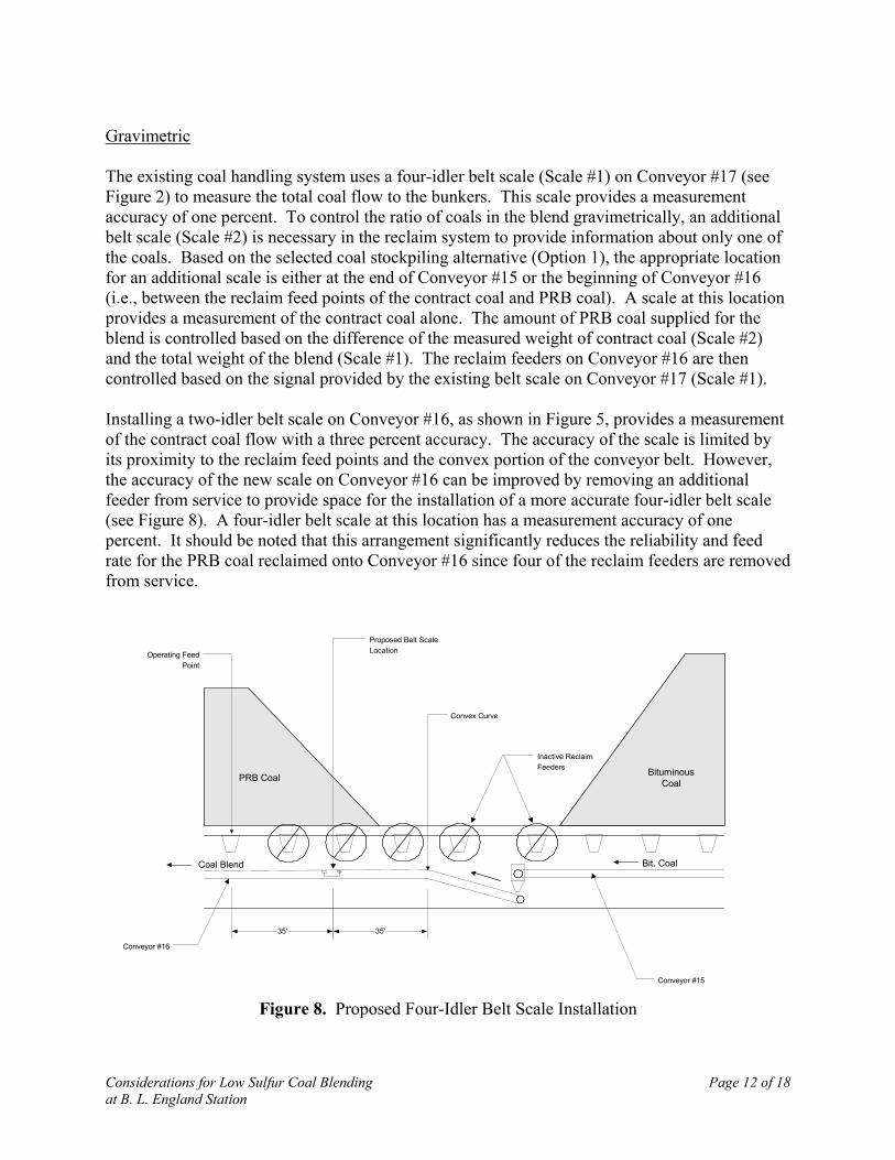
Installing a two-idler belt scale on Conveyor #16, as shown in Figure 5, provides a measurementof the contract coal flow with a three percent accuracy. The accuracy of the scale is limited byits proximity to the reclaim feed points and the convex portion of the conveyor belt. However,the accuracy of the new scale on Conveyor #16 can be improved by removing an additionalfeeder from service to provide space for the installation of a more accurate four-idler belt scale(see Figure 8). A four-idler belt scale at this location has a measurement accuracy of onepercent. It should be noted that this arrangement significantly reduces the reliability and feedrate for the PRB coal reclaimed onto Conveyor #16 since four of the reclaim feeders are removedfrom service.
Conveyor #16
Conveyor #15
35'35'
PRB Coal BituminousCoal
Proposed Belt ScaleLocation
Convex Curve
Operating FeedPoint
Bit. CoalCoal Blend
Inactive ReclaimFeeders
Figure 8. Proposed Four-Idler Belt Scale Installation

Considerations for Low Sulfur Coal Blending Page 13 of 18at B. L. England Station
A comparison of the impact of the belt scale accuracy on the control of fuel sulfur was alsoperformed. This comparison is impacted by both the accuracy of the two belt scales operating inparallel and the variability of the coal sulfur content. Table 5 summarizes the results of thisevaluation.
Table 5. Impact of Coal Sulfur Content Variation on Blend Accuracy
Coal Blend Sulfur Content (%)Based on Differences in Individual Fuel
Sulfur VariationsConveyor #16 Scale Type
Minimum Maximum AverageTwo-Idler (Figure 5)3% Accuracy 1.44 2.09 1.73
Four-Idler (Figure 8)1% Accuracy 1.46 2.05 1.73
This evaluation illustrates that the higher scale accuracy has only a limited impact on the rangeof sulfur content of the blended coal. The higher cost of the four-idler scale and the operationalimpact of removing another reclaim feeder from service makes this option less attractive tosupply BLE-1 with a blended coal.
Parametric
The most direct method of controlling the coal blending process requires an on-line nuclear coalanalyzer. These analyzers utilize gamma radiation to determine the elemental composition ofcoal. On-line nuclear coal analyzers provide fast, accurate, real-time information concerning theelemental composition of coal including identification of sulfur, carbon, oxygen, and hydrogen.In addition, these analyzers can measure moisture and ash content. Based on the measuredconstituents, the analyzer includes software to determine the heating value (Btu/lb) of the coal.As a result, on-line nuclear coal analyzers have the potential to optimize the sulfur content andthe heating value of the coal blend, with corresponding environmental and economic advantagesfor the operating plant.
On-line nuclear coal analyzers have a sulfur content accuracy of 0.5%. Coupling the control ofthe feeders with the existing belt scale and a new on-line nuclear analyzer located in the crusherhouse provides the most accurate control of the fuel blend. However, equipment costs combinedwith installation costs make this blending control alternative more than nine times the cost of thetwo-idler belt scale. Further, implementation of an on-line analyzer requires installation of a beltsampling system (cutter) to route a reduced portion of the coal flow to the equipment for analysisas well as to provide a means to calibrate and verify the nuclear analyzer. This sampling systemincreases the total cost by roughly 35%. Although the on-line nuclear coal analyzer provides themost accurate means for controlling a coal blend, the higher capital costs and complexities ofintegrating such a system are not justified for the BLE-1 on-site blending installation. Therecommended approach is the addition of the two-idler belt scale for control of the fuel blending.

Considerations for Low Sulfur Coal Blending Page 14 of 18at B. L. England Station
PRB Coal Handling Modifications
The use of PRB coal in the blended fuel for BLE-1 significantly complicates the modificationsrequired for on-site blending at B. L. England Station. Specifically, PRB coal is very dusty andhas a propensity for spontaneous combustion. Particular emphasis was needed in two areas tosafely handle PRB coal, specifically:
Dust suppression systems to reduce fugitive coal dust, and
Effective wash-down techniques to prevent the accumulation of PRB coal along the coalhandling system.
The following changes are required in the coal handling system to safely and effectively operateBLE-1 with a PRB coal blend.
Rotary Dumper Dust Suppression
During the low sulfur coal testing, the PRB portion of the test coal blend generated significantdust in the rotary dumper building. The existing spray nozzles, which apply water to coal as it isunloaded, were ineffective. The following changes to control PRB fugitive dust from the rotarydumper building were recommended by dust suppression system vendors:
• An effective dust suppression system that applies a water/surfactant solution to the coal atthe level of the rotating train car and at the level of the hoppers below is required (top andbottom spray).
• The areas around the grizzly screens in the dumper building need to be covered orblocked-off with steel plates to limit the amount of dust that can resurface after the coalhas passed through the screens.
• Although this change is not planned, dust curtains may be installed at the openings of thedumper building to limit airflow inside, as well as to prevent fugitive dust from exitingthe building.
The Johnson-March dust suppression system currently installed in the rotary dumper house atB. L. England Station is not fully operable. This system is equipped with top and bottom spraysto provide a water/surfactant solution to the rotating car and coal hoppers at a rate of about 1.5gallons per ton of coal. To effectively suppress PRB coal dust at the rotary dumper building, thissystem requires refurbishment to improve its dust suppression capabilities.
Crusher House
The crusher house is another area along the coal handling system with the potential to generateand accumulate significant amounts of PRB coal dust. Many plants that fire PRB coal have dustsuppression systems that apply foamed surfactants to the coal at the transfer point out of thecrushers. Currently, B. L. England Station has a ChemLink dust suppression system (i.e., foam

Considerations for Low Sulfur Coal Blending Page 15 of 18at B. L. England Station
system) installed at the crusher house, but it is not operable. A new foam dust suppressionsystem is recommended for this location.
The crushers are periodically operated without any coal flow when switching between thebunkering of BLE-1 and BLE-2. This operation generates significant amounts of dust in thecrusher house. To control the dust inside the crusher house during this type of operation, a newwindmilling dust suppression system is required.
Besides dust suppression, housekeeping in the crusher house is critical to prevent PRB coal dustaccumulation. The crusher house needs to be washed down daily with water hoses to clear anyaccumulated dust. To facilitate this process, high dust collecting areas (i.e., flat surfaces andcorners) must be filled with lightweight concrete on a slope to ensure that the washed down coalwill run-off. In addition, the bottom floor of the crusher house requires modification to allow thewash down water to drain out of the crusher house and into the sumps.
Conveyors and Transition Points
Housekeeping of coal dust around the conveyors and at the transition points is also importantwhile handling PRB coal blends. Based on the experience of using the fire protection system asa temporary wash-down technique during the test burns with PRB coal, it was concluded that adedicated wash-down system along all conveyor belts is required. The system consists of hoses,strategically installed at 50-foot intervals along the coal handling system, which are suppliedfrom a dedicated wash-down system source. At least 30 hose stations along the coal handlingsystem are required. In addition, the water distribution system (i.e., tank, piping, and pumps) forwash-down use is needed.
An effective wash-down system also requires adequate drainage. Currently, the run-off systemin the coal handling area consists of a series of sumps leading to a coal stockpile settling pond.Water is periodically pumped from the coal stockpile settling pond to the water treatmentfacility. During the test burns, this run-off system was capable of handling the wash-down thatoccurred. However, the drainage network requires changes for continuous wash-down use,including new drainage ditches, increased sump capacities, upgraded pumps and controls, anddelivery piping. One identified source of the water for the wash-down supply tank is the watertreatment system.
Bunker House
The final area along the coal handling system that requires PRB coal dust control and clean up isin the bunker house. Similar to the crusher house, the bunker house contains many flat surfacesthat allow for the accumulation of PRB coal. Therefore, to facilitate housekeeping and preventaccumulation of coal dust, B. L. England Station must fill in areas prone to dust collection withlightweight concrete placed on a slope.
The wash-down method discussed for the crusher house is not an effective method for collectingand removing accumulated dust in the bunker house because there is no provision for drainage.In particular, the tripper conveyor tensioning pit, which is located between Conveyor #2 and the

Considerations for Low Sulfur Coal Blending Page 16 of 18at B. L. England Station
tripper, accumulates large amounts of coal that cannot be cleared by washing. B. L. EnglandStation personnel periodically remove accumulations of coal from this area using the existingvacuum system or by manual collection. However, the existing vacuum system is not reliableand has pluggage problems. To prevent accumulation of PRB coal, B. L. England Station mustconsider a more effective vacuum system that accesses all areas of the bunker house and safelydisposes of the collected coal.
As a means of limiting the amount of coal dust generated in the bunker house, the tripper mustbe equipped with a cover to seal the entire length of the bunker opening, except for the areawhere the tripper is dispensing coal. The B. L. England Station tripper has this capability, butthe bunker cover is not currently installed on the tripper. To assist in dust control in the bunkerhouse, these bunker covers must be reinstalled.
Fire Protection
Because PRB coal has a propensity to spontaneously combust, the fire protection system alongthe coal handling system must be equipped with adequate fire suppression and detectioncapabilities. A robust fire protection system is particularly important at B. L. England Stationsince the coal handling system is not redundant and any fire event would impact operations atboth BLE-1 and BLE-2.
The current fire protection system at B. L. England Station protects most of the area along theconveyor belts with automated nozzles that run the length of the conveyors. A hydrant located atthe southeast corner of the rotary dumper provides fire suppression in the car dumper and for thecoal pile. Additional dry chemical extinguishers are required for controlling the local “hot spot”fires typical of PRB coal stockpiling. In addition to fire suppression, adequate fire detection isimportant when handling PRB coal. Combustible gas detectors and CO detectors can beinstalled at BLE-1 to prevent potential fires and detect active fires, respectively.
Conclusion
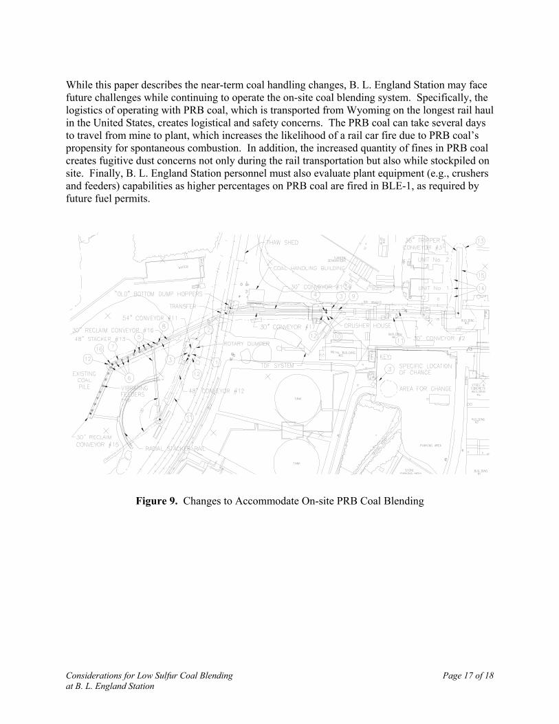
Detailed design of the changes for on-site blending of PRB coal was initiated at the conclusion ofthe negotiations for the new three-year fuel permit for BLE-1 in May 2003. Figure 9 illustratesthe changes necessary to accommodate on-site PRB coal blending and Figure 10 shows theconceptual schedule for the implementation of these changes. The fuel permit required that thesechanges be implemented to support continuous operation with on-site blending with PRB coalstarting in January 2004.
This paper summarizes all the areas of the coal handling system that require changes toaccommodate the continuous firing of an on-site blended coal to satisfy the requirements of thecurrent fuel permit for BLE-1. The changes include a modified coal stockpile, the installation ofon-site blending capability, and changes to accommodate the handling of PRB coal. By selectingthe least costly (less than $800,000) and least disruptive approach for implementing the changes,B. L. England Station personnel expect to achieve on-site coal blending in approximately ninemonths. Based on the lower cost of on-site blended fuel using PRB coal, the capital costs forthese changes have a payback period of less than two years.
Considerations for Low Sulfur Coal Blending Page 17 of 18at B. L. England Station
While this paper describes the near-term coal handling changes, B. L. England Station may facefuture challenges while continuing to operate the on-site coal blending system. Specifically, thelogistics of operating with PRB coal, which is transported from Wyoming on the longest rail haulin the United States, creates logistical and safety concerns. The PRB coal can take several daysto travel from mine to plant, which increases the likelihood of a rail car fire due to PRB coal’spropensity for spontaneous combustion. In addition, the increased quantity of fines in PRB coalcreates fugitive dust concerns not only during the rail transportation but also while stockpiled onsite. Finally, B. L. England Station personnel must also evaluate plant equipment (e.g., crushersand feeders) capabilities as higher percentages on PRB coal are fired in BLE-1, as required byfuture fuel permits.
Figure 9. Changes to Accommodate On-site PRB Coal Blending

Considerations for Low Sulfur Coal Blending Page 18 of 18at B. L. England Station
ID Task NameQ2 03
MayMar SepFeb DecNov
1 10wCoal Handling Conceptual Engineering
5 9wCoal Handling Detailed Engineering
7 20wCar Dumper Modifications
8 14wCrusher House Modifications
9 26wConveyor Modifications
11 26wCoal Stockpile Reclaim Modifications
Jan
3 7wFuel Permit Negotiation
4 8wConectiv Project Approvals
2 1/28/2003Issue Wrap-up Report
Sixth Stay Expires
12 30wHousekeeping Modifications
13 11wOther Improvements
10 9/22/2003BLE-1 Fall Outage
Q4 03Q3 03Q1 03
JunApr OctJul Aug
14 1/2/2004Initiate On-Site Blending
Start
11/20/2002
1/28/2003
2/13/2003
1/29/2003
4/3/2003
6/5/2003
2/28/2003
6/5/2003
6/5/2003
9/22/2003
6/5/2003
6/5/2003
9/22/2003
1/2/2004
1/28/2003
1/28/2003
4/2/2003
3/25/2003
6/4/2003
10/22/2003
2/28/2003
9/10/2003
12/3/2003
9/22/2003
12/3/2003
12/31/2003
12/5/2003
1/2/2004
Finish
6 2/28/2003
Figure 10. Initial Schedule for On-site PRB Coal Blending Implementation