Connector Gages and Connector Gage Kits - maurymw.com · SMA 0.0005 A027 Two push-on gages measure...
43
// MARCH 2019 Connector Gages and Connector Gage Kits DATA SHEET / 2Y-051 MODELS: A048A - 1.85mm/2.4mm A050A - 2.92mm (K)/3.5mm A020K - Type N A034B - 2.92mm (K)/3.5mm A034E - 2.92mm (K)/3.5mm A035E - 1.85mm/2.4mm A028D - 7mm A007A - Type N A020A - Type N A020D - Type N A020G - Type N (75 ohms) A012A - BNC/TNC A027 - SMA A027A - SMA A027G - SMA A027M - SMA A042A - SMP/GPO™
Transcript of Connector Gages and Connector Gage Kits - maurymw.com · SMA 0.0005 A027 Two push-on gages measure...
/ / MARCH 2019
Connector Gages and Connector Gage KitsDATA S H E E T / 2 Y- 0 5 1
MODELS:A048A - 1.85mm/2.4mmA050A - 2.92mm (K)/3.5mmA020K - Type NA034B - 2.92mm (K)/3.5mmA034E - 2.92mm (K)/3.5mmA035E - 1.85mm/2.4mmA028D - 7mmA007A - Type N
A020A - Type NA020D - Type NA020G - Type N (75 ohms)A012A - BNC/TNCA027 - SMAA027A - SMAA027G - SMAA027M - SMAA042A - SMP/GPO™

M AU R Y M W. C O M / DATA S H E E T / 2 Y- 0 5 11
1 GPO™ is a trademark of the Gilbert Engineering Co., Inc.
A048A 1.85mm/2.4mm Digital Connector Gage Kit
A048A (Female) and A048B (Male) Digital Gages with Master Blocks (Enlarged)
Connector Gages and Connector Gage KitsGENERAL INFORMATION
Description
Maury connector gage kits provide an easy and accurate way to measure critical linear interface dimensions of most coaxial connectors. Each kit consist of gages with specially adapted indicators, and the bushings and pins needed to mate with specified connectors. Master setting gages are used to adjust the dial indicators (or digital indicators) to zero, before push-on or thread-on gages are mated with connectors to measure the distance from a given interface (male shoulder, etc.) to the outer conductor mating plane. The table below lists available models. Additional information is found in the referenced data sheets.
Why You Need Connector Gages
The Importance of checking the critical mechanical dimensions of your coaxial connectors before mating cannot be overstated. Superior electrical performance depends on making sure all the coaxial connectors in you test setup are operating within their specified tolerances. Pin depth and position of the center conductors are especially critical in that regard.
If the male and female contacts are recessed beyond tolerance they will exhibit a "gap-fit" connection when mated. This causes significant reduction of electrical performance.
If the male and female contacts protrude beyond their specified tolerances they will exhibit an "interference-fit" when mated. This will also degrade electrical performance, with adverse effects on measurement accuracy, and may result in catastrophic damage to the center connectors and contacts.
Since 1962 Maury Microwave has been designing connector gage kits that provide the best method of checking pin depth and position in all the most popular coaxial connector types. Today these include digital gage kits in 1.85mm/2.4mm and 2.92mm/3.5mm and Type N connector types, and dial-indicator gage kits in 1.85mm/2.4mm, 2.92mm/3.5mm, 7mm, type N (in 50 ohm and 75 ohm models), BNC, TNC, SMA and SMP/GPO™1 connector types.
All Maury connector gage kits are designed for superior durability, stability and repeatability. Each kit includes at least one connector gage with the master gage block or blocks necessary to ensure the accuracy of the gages. Kits are available as metrology grade thread-on designs or hand-held push-on designs.
Features
> Direct Reading, Self-Checking
> Accurate, Easy to Use
> Digital and/or Dial Indicator Styles
Available Models - Digital Indicator Style
Connector Type Dial Resolution (Inches) Model Description Page Ref.
1.85mm/2.4mm
0.001mm/0.00004 in. A048ATwo thread-on metrology grade digital gages measure female and male
contact pin locations.3
2.92mm (K)/3.5mm 0.001mm/0.00004 in. A050ATwo thread-on metrology grade digital gages measure female and male
contact pin locations.7
Type N 0.001mm/0.00004 in. A020KTwo thread-on metrology grade digital gages measure type N female and male connectors, sliding loads, airlines, two-port standards, VNA test port
adapters, etc.11
M AU R Y M W. C O M / DATA S H E E T / 2 Y- 0 5 1 2
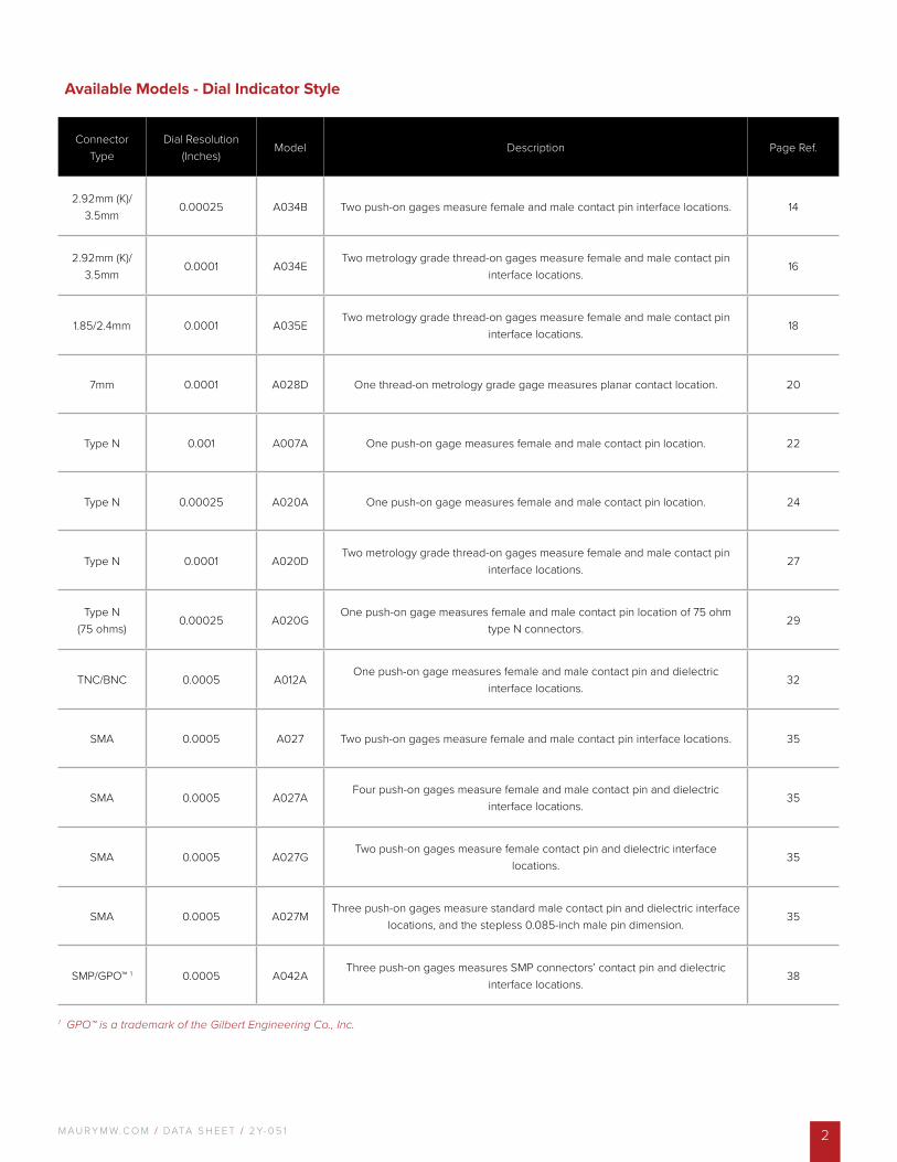
Available Models - Dial Indicator Style
Connector Type
Dial Resolution (Inches)
Model Description Page Ref.
2.92mm (K)/ 3.5mm
0.00025 A034B Two push-on gages measure female and male contact pin interface locations. 14
2.92mm (K)/ 3.5mm
0.0001 A034ETwo metrology grade thread-on gages measure female and male contact pin
interface locations.16
1.85/2.4mm 0.0001 A035ETwo metrology grade thread-on gages measure female and male contact pin
interface locations.18
7mm 0.0001 A028D One thread-on metrology grade gage measures planar contact location. 20
Type N 0.001 A007A One push-on gage measures female and male contact pin location. 22
Type N 0.00025 A020A One push-on gage measures female and male contact pin location. 24
Type N 0.0001 A020DTwo metrology grade thread-on gages measure female and male contact pin
interface locations.27
Type N (75 ohms)
0.00025 A020GOne push-on gage measures female and male contact pin location of 75 ohm
type N connectors.29
TNC/BNC 0.0005 A012AOne push-on gage measures female and male contact pin and dielectric
interface locations.32
SMA 0.0005 A027 Two push-on gages measure female and male contact pin interface locations. 35
SMA 0.0005 A027AFour push-on gages measure female and male contact pin and dielectric
interface locations.35
SMA 0.0005 A027GTwo push-on gages measure female contact pin and dielectric interface
locations.35
SMA 0.0005 A027MThree push-on gages measure standard male contact pin and dielectric interface
locations, and the stepless 0.085-inch male pin dimension.35
SMP/GPO™ 1 0.0005 A042AThree push-on gages measures SMP connectors’ contact pin and dielectric
interface locations.38
1 GPO™ is a trademark of the Gilbert Engineering Co., Inc.
M AU R Y M W. C O M / DATA S H E E T / 2 Y- 0 5 13
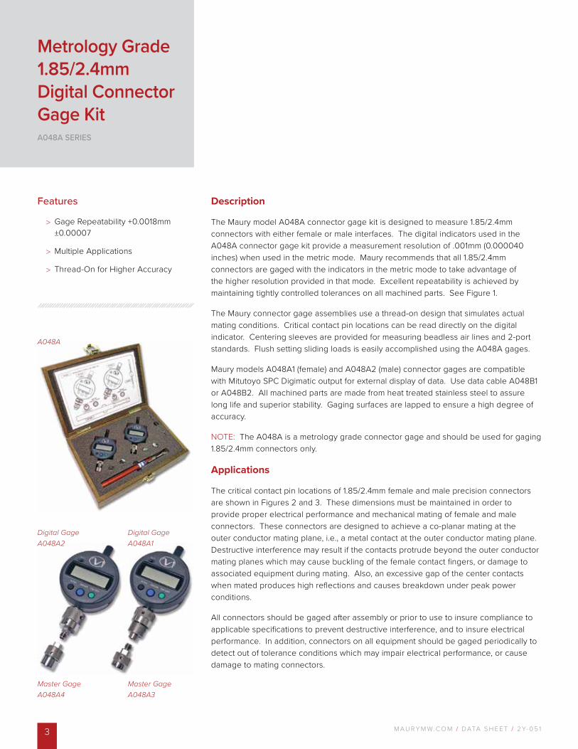
Digital Gage A048A2
A048A
Digital Gage A048A1
Master Gage A048A4
Master Gage A048A3
Description
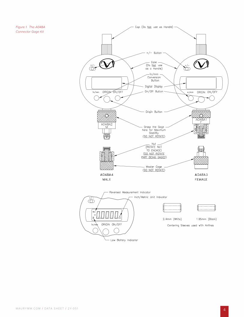
The Maury model A048A connector gage kit is designed to measure 1.85/2.4mm connectors with either female or male interfaces. The digital indicators used in the A048A connector gage kit provide a measurement resolution of .001mm (0.000040 inches) when used in the metric mode. Maury recommends that all 1.85/2.4mm connectors are gaged with the indicators in the metric mode to take advantage of the higher resolution provided in that mode. Excellent repeatability is achieved by maintaining tightly controlled tolerances on all machined parts. See Figure 1.
The Maury connector gage assemblies use a thread-on design that simulates actual mating conditions. Critical contact pin locations can be read directly on the digital indicator. Centering sleeves are provided for measuring beadless air lines and 2-port standards. Flush setting sliding loads is easily accomplished using the A048A gages.
Maury models A048A1 (female) and A048A2 (male) connector gages are compatible with Mitutoyo SPC Digimatic output for external display of data. Use data cable A048B1 or A048B2. All machined parts are made from heat treated stainless steel to assure long life and superior stability. Gaging surfaces are lapped to ensure a high degree of accuracy.
NOTE: The A048A is a metrology grade connector gage and should be used for gaging 1.85/2.4mm connectors only.
Applications
The critical contact pin locations of 1.85/2.4mm female and male precision connectors are shown in Figures 2 and 3. These dimensions must be maintained in order to provide proper electrical performance and mechanical mating of female and male connectors. These connectors are designed to achieve a co-planar mating at the outer conductor mating plane, i.e., a metal contact at the outer conductor mating plane. Destructive interference may result if the contacts protrude beyond the outer conductor mating planes which may cause buckling of the female contact fingers, or damage to associated equipment during mating. Also, an excessive gap of the center contacts when mated produces high reflections and causes breakdown under peak power conditions.
All connectors should be gaged after assembly or prior to use to insure compliance to applicable specifications to prevent destructive interference, and to insure electrical performance. In addition, connectors on all equipment should be gaged periodically to detect out of tolerance conditions which may impair electrical performance, or cause damage to mating connectors.
Features
> Gage Repeatability +0.0018mm ±0.00007
> Multiple Applications
> Thread-On for Higher Accuracy
Metrology Grade 1.85/2.4mm Digital Connector Gage KitA048A SERIES
M AU R Y M W. C O M / DATA S H E E T / 2 Y- 0 5 1 4
Figure 1. The A048A Connector Gage Kit
M AU R Y M W. C O M / DATA S H E E T / 2 Y- 0 5 15
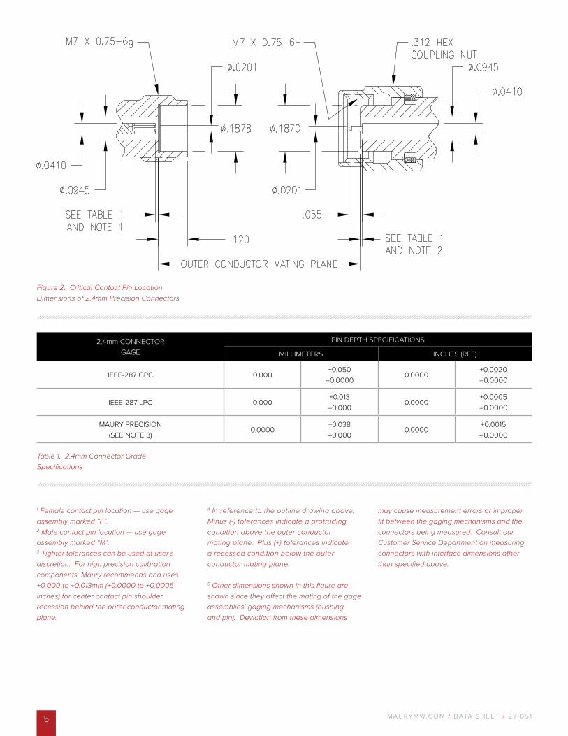
Figure 2. Critical Contact Pin Location Dimensions of 2.4mm Precision Connectors
1 Female contact pin location — use gage assembly marked “F”.2 Male contact pin location — use gage assembly marked “M”.3 Tighter tolerances can be used at user’s discretion. For high precision calibration components, Maury recommends and uses +0.000 to +0.013mm (+0.0000 to +0.0005 inches) for center contact pin shoulder recession behind the outer conductor mating plane.
4 In reference to the outline drawing above: Minus (-) tolerances indicate a protruding condition above the outer conductor mating plane. Plus (+) tolerances indicate a recessed condition below the outer conductor mating plane.
5 Other dimensions shown in this figure are shown since they affect the mating of the gage assemblies’ gaging mechanisms (bushing and pin). Deviation from these dimensions
may cause measurement errors or improper fit between the gaging mechanisms and the connectors being measured. Consult our Customer Service Department on measuring connectors with interface dimensions other than specified above.
2.4mm CONNECTORGAGE
PIN DEPTH SPECIFICATIONS
MILLIMETERS INCHES (REF)
IEEE-287 GPC 0.000+0.050
–0.00000.0000
+0.0020–0.0000
IEEE-287 LPC 0.000+0.013–0.000
0.0000+0.0005–0.0000
MAURY PRECISION(SEE NOTE 3)
0.0000+0.038–0.000
0.0000+0.0015–0.0000
Table 1. 2.4mm Connector Grade Specifications
M AU R Y M W. C O M / DATA S H E E T / 2 Y- 0 5 1 6
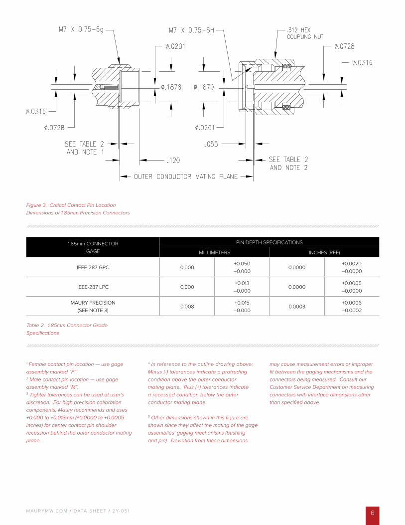
Figure 3. Critical Contact Pin Location Dimensions of 1.85mm Precision Connectors
1 Female contact pin location — use gage assembly marked “F”.2 Male contact pin location — use gage assembly marked “M”.3 Tighter tolerances can be used at user’s discretion. For high precision calibration components, Maury recommends and uses +0.000 to +0.013mm (+0.0000 to +0.0005 inches) for center contact pin shoulder recession behind the outer conductor mating plane.
4 In reference to the outline drawing above: Minus (-) tolerances indicate a protruding condition above the outer conductor mating plane. Plus (+) tolerances indicate a recessed condition below the outer conductor mating plane.
5 Other dimensions shown in this figure are shown since they affect the mating of the gage assemblies’ gaging mechanisms (bushing and pin). Deviation from these dimensions
may cause measurement errors or improper fit between the gaging mechanisms and the connectors being measured. Consult our Customer Service Department on measuring connectors with interface dimensions other than specified above.
1.85mm CONNECTORGAGE
PIN DEPTH SPECIFICATIONS
MILLIMETERS INCHES (REF)
IEEE-287 GPC 0.000+0.050–0.000
0.0000+0.0020–0.0000
IEEE-287 LPC 0.000+0.013–0.000
0.0000+0.0005–0.0000
MAURY PRECISION(SEE NOTE 3)
0.008+0.015–0.000
0.0003+0.0006–0.0002
Table 2. 1.85mm Connector Grade Specifications
M AU R Y M W. C O M / DATA S H E E T / 2 Y- 0 5 17
Digital Gage A050A2
A050A
Digital Gage A050A1
Master Gage A050A4
Master Gage A050A3
Description
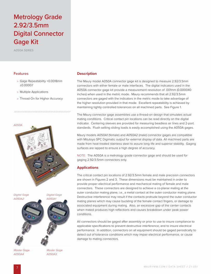
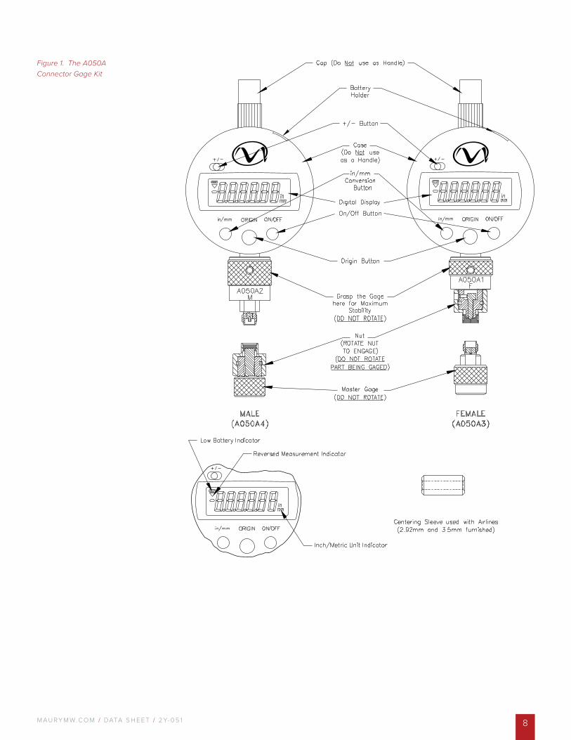
The Maury model A050A connector gage kit is designed to measure 2.92/3.5mm connectors with either female or male interfaces. The digital indicators used in the A050A connector gage kit provide a measurement resolution of .001mm (0.000040 inches) when used in the metric mode. Maury recommends that all 2.92/3.5mm connectors are gaged with the indicators in the metric mode to take advantage of the higher resolution provided in that mode. Excellent repeatability is achieved by maintaining tightly controlled tolerances on all machined parts. See Figure 1.
The Maury connector gage assemblies use a thread-on design that simulates actual mating conditions. Critical contact pin locations can be read directly on the digital indicator. Centering sleeves are provided for measuring beadless air lines and 2-port standards. Flush setting sliding loads is easily accomplished using the A050A gages.
Maury models A050A1 (female) and A050A2 (male) connector gages are compatible with Mitutoyo SPC Digimatic output for external display of data. All machined parts are made from heat treated stainless steel to assure long life and superior stability. Gaging surfaces are lapped to ensure a high degree of accuracy.
NOTE: The A050A is a metrology grade connector gage and should be used for gaging 2.92/3.5mm connectors only.
Applications
The critical contact pin locations of 2.92/3.5mm female and male precision connectors are shown in Figures 2 and 3. These dimensions must be maintained in order to provide proper electrical performance and mechanical mating of female and male connectors. These connectors are designed to achieve a co-planar mating at the outer conductor mating plane, i.e., a metal contact at the outer conductor mating plane. Destructive interference may result if the contacts protrude beyond the outer conductor mating planes which may cause buckling of the female contact fingers, or damage to associated equipment during mating. Also, an excessive gap of the center contacts when mated produces high reflections and causes breakdown under peak power conditions.
All connectors should be gaged after assembly or prior to use to insure compliance to applicable specifications to prevent destructive interference, and to insure electrical performance. In addition, connectors on all equipment should be gaged periodically to detect out of tolerance conditions which may impair electrical performance, or cause damage to mating connectors.
Features
> Gage Repeatability +0.0018mm ±0.00007
> Multiple Applications
> Thread-On for Higher Accuracy
Metrology Grade 2.92/3.5mm Digital Connector Gage KitA050A SERIES
M AU R Y M W. C O M / DATA S H E E T / 2 Y- 0 5 1 8
Figure 1. The A050A Connector Gage Kit
M AU R Y M W. C O M / DATA S H E E T / 2 Y- 0 5 19
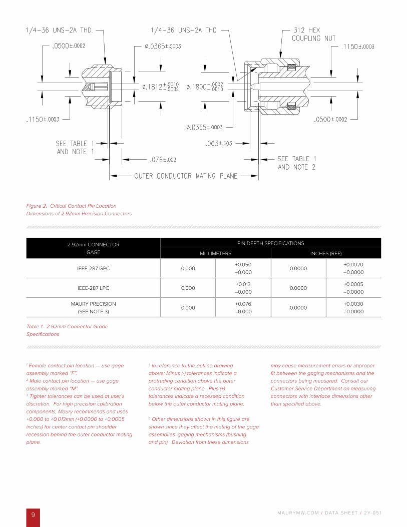
Figure 2. Critical Contact Pin Location Dimensions of 2.92mm Precision Connectors
1 Female contact pin location — use gage assembly marked “F”.2 Male contact pin location — use gage assembly marked “M”.3 Tighter tolerances can be used at user’s discretion. For high precision calibration components, Maury recommends and uses +0.000 to +0.013mm (+0.0000 to +0.0005 inches) for center contact pin shoulder recession behind the outer conductor mating plane.
4 In reference to the outline drawing above: Minus (-) tolerances indicate a protruding condition above the outer conductor mating plane. Plus (+) tolerances indicate a recessed condition below the outer conductor mating plane. 5 Other dimensions shown in this figure are shown since they affect the mating of the gage assemblies’ gaging mechanisms (bushing and pin). Deviation from these dimensions
may cause measurement errors or improper fit between the gaging mechanisms and the connectors being measured. Consult our Customer Service Department on measuring connectors with interface dimensions other than specified above.
2.92mm CONNECTORGAGE
PIN DEPTH SPECIFICATIONS
MILLIMETERS INCHES (REF)
IEEE-287 GPC 0.000+0.050–0.000
0.0000+0.0020–0.0000
IEEE-287 LPC 0.000+0.013–0.000
0.0000+0.0005–0.0000
MAURY PRECISION(SEE NOTE 3)
0.000+0.076–0.000
0.0000+0.0030–0.0000
Table 1. 2.92mm Connector Grade Specifications
M AU R Y M W. C O M / DATA S H E E T / 2 Y- 0 5 1 10
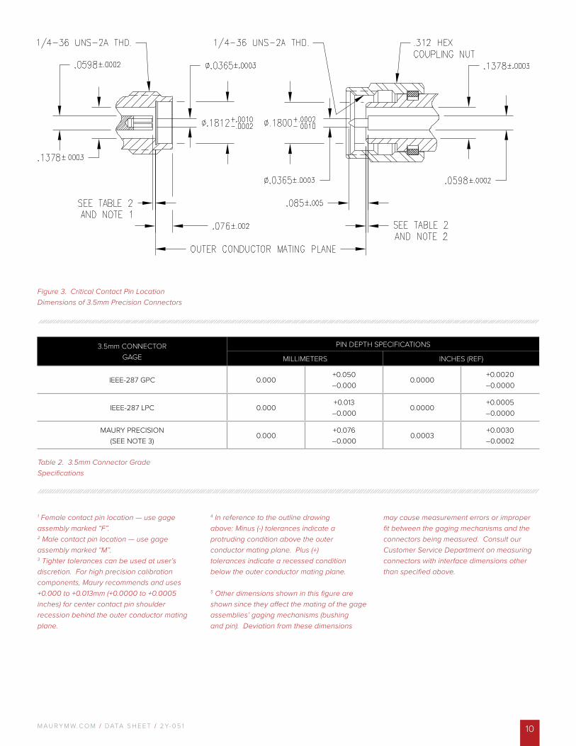
Figure 3. Critical Contact Pin Location Dimensions of 3.5mm Precision Connectors
1 Female contact pin location — use gage assembly marked “F”.2 Male contact pin location — use gage assembly marked “M”.3 Tighter tolerances can be used at user’s discretion. For high precision calibration components, Maury recommends and uses +0.000 to +0.013mm (+0.0000 to +0.0005 inches) for center contact pin shoulder recession behind the outer conductor mating plane.
4 In reference to the outline drawing above: Minus (-) tolerances indicate a protruding condition above the outer conductor mating plane. Plus (+) tolerances indicate a recessed condition below the outer conductor mating plane. 5 Other dimensions shown in this figure are shown since they affect the mating of the gage assemblies’ gaging mechanisms (bushing and pin). Deviation from these dimensions
may cause measurement errors or improper fit between the gaging mechanisms and the connectors being measured. Consult our Customer Service Department on measuring connectors with interface dimensions other than specified above.
3.5mm CONNECTORGAGE
PIN DEPTH SPECIFICATIONS
MILLIMETERS INCHES (REF)
IEEE-287 GPC 0.000+0.050–0.000
0.0000+0.0020–0.0000
IEEE-287 LPC 0.000+0.013–0.000
0.0000+0.0005–0.0000
MAURY PRECISION(SEE NOTE 3)
0.000+0.076–0.000
0.0003+0.0030–0.0002
Table 2. 3.5mm Connector Grade Specifications
M AU R Y M W. C O M / DATA S H E E T / 2 Y- 0 5 111
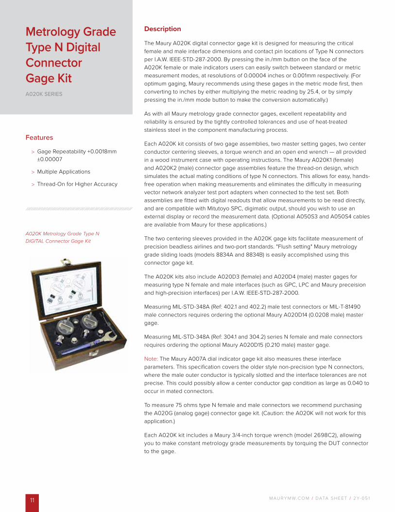
A020K Metrology Grade Type N DIGITAL Connector Gage Kit
Description
The Maury A020K digital connector gage kit is designed for measuring the critical female and male interface dimensions and contact pin locations of Type N connectors per I.A.W. IEEE-STD-287-2000. By pressing the in./mm button on the face of the A020K female or male indicators users can easily switch between standard or metric measurement modes, at resolutions of 0.00004 inches or 0.001mm respectively. (For optimum gaging, Maury recommends using these gages in the metric mode first, then converting to inches by either multiplying the metric reading by 25.4, or by simply pressing the in./mm mode button to make the conversion automatically.)
As with all Maury metrology grade connector gages, excellent repeatability and reliability is ensured by the tightly controlled tolerances and use of heat-treated stainless steel in the component manufacturing process.
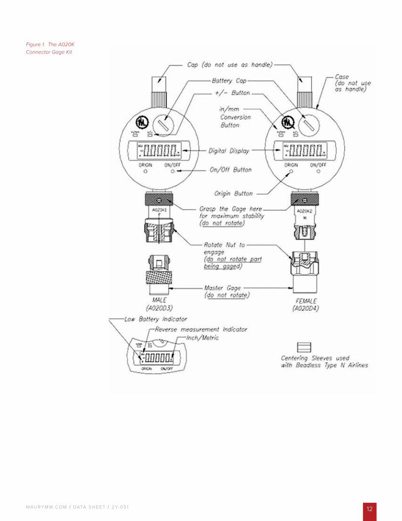
Each A020K kit consists of two gage assemblies, two master setting gages, two center conductor centering sleeves, a torque wrench and an open end wrench — all provided in a wood instrument case with operating instructions. The Maury A020K1 (female) and A020K2 (male) connector gage assemblies feature the thread-on design, which simulates the actual mating conditions of type N connectors. This allows for easy, hands-free operation when making measurements and eliminates the difficulty in measuring vector network analyzer test port adapters when connected to the test set. Both assemblies are fitted with digital readouts that allow measurements to be read directly, and are compatible with Mitutoyo SPC, digimatic output, should you wish to use an external display or record the measurement data. (Optional A050S3 and A050S4 cables are available from Maury for these applications.)
The two centering sleeves provided in the A020K gage kits facilitate measurement of precision beadless airlines and two-port standards. "Flush setting" Maury metrology grade sliding loads (models 8834A and 8834B) is easily accomplished using this connector gage kit.
The A020K kits also include A020D3 (female) and A020D4 (male) master gages for measuring type N female and male interfaces (such as GPC, LPC and Maury preceision and high-precision interfaces) per I.A.W. IEEE-STD-287-2000.
Measuring MIL-STD-348A (Ref: 402.1 and 402.2) male test connectors or MIL-T-81490 male connectors requires ordering the optional Maury A020D14 (0.0208 male) master gage.
Measuring MIL-STD-348A (Ref: 304.1 and 304.2) series N female and male connectors requires ordering the optional Maury A020D15 (0.210 male) master gage.
Note: The Maury A007A dial indicator gage kit also measures these interface parameters. This specification covers the older style non-precision type N connectors, where the male outer conductor is typically slotted and the interface tolerances are not precise. This could possibly allow a center conductor gap condition as large as 0.040 to occur in mated connectors.
To measure 75 ohms type N female and male connectors we recommend purchasing the A020G (analog gage) connector gage kit. (Caution: the A020K will not work for this application.)
Each A020K kit includes a Maury 3/4-inch torque wrench (model 2698C2), allowing you to make constant metrology grade measurements by torquing the DUT connector to the gage.
Features
> Gage Repeatability +0.0018mm ±0.00007
> Multiple Applications
> Thread-On for Higher Accuracy
Metrology Grade Type N Digital Connector Gage KitA020K SERIES
M AU R Y M W. C O M / DATA S H E E T / 2 Y- 0 5 1 12
Figure 1. The A020K Connector Gage Kit
M AU R Y M W. C O M / DATA S H E E T / 2 Y- 0 5 113
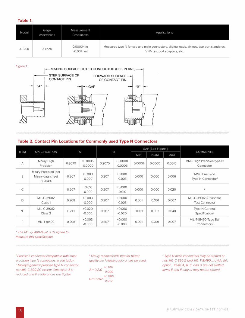
Table 2. Contact Pin Locations for Commonly used Type N Connectors
ITEM SPECIFICATION A BGAP (See Figure 1)
COMMENTSMIN NOM MAX
AMaury HighPrecision
0.2070+0.0005-0.0000
0.2070+0.0000-0.0005
0.0000 0.0000 0.0010MMC High Precision type N
Connector
BMaury Precision (per
Maury data sheet 5E-049)
0.207+0.003-0.000
0.207+0.000-0.003
0.000 0.000 0.006MMC Precision
Type N Connector1
C — 0.207+0.010-0.000
0.207+0.000-0.010
0.000 0.000 0.020 2
DMIL-C-39012
Class 10.208
+0.003-0.000
0.207+0.000-0.003
0.001 0.001 0.007MIL-C-39012C Standard
Test Connector
*EMIL-C-39012
Class 20.210
+0.020-0.000
0.207+0.000-0.020
0.003 0.003 0.040Type N GeneralSpecification3
F MIL-T-81490 0.208+0.003-0.000
0.207+0.000-0.003
0.001 0.001 0.007MIL-T-81490 Type EW
Connectors
1 Precision connector compatible with most precision type N connectors in use today. 2 Maury's general purpose type N connector per MIL-C-39012C except dimension A is reduced and the tolerances are tighter.
3 Maury recommends that for better quality the following tolerances be used: A = 0.210 B = 0.207
4 Type N male connectors may be slotted or not; MIL-C-39012 and MIL-T-81490 provide this option. Items A, B, C, and D are not slotted. Items E and F may or may not be slotted.
Table 1.
ModelGage
AssembliesMeasurementResolutions
Applications
A020K 2 each0.00004 in.(0.001mm)
Measures type N female and male connectors, sliding loads, airlines, two-port standards, VNA test port adapters, etc.
* The Maury A007A kit is designed to measure this specification.
+0.010 -0.000+0.000 -0.010
Figure 1
M AU R Y M W. C O M / DATA S H E E T / 2 Y- 0 5 1 14
A034B 3.5mm/2.92mm Precision Connector Gage Kit
Description
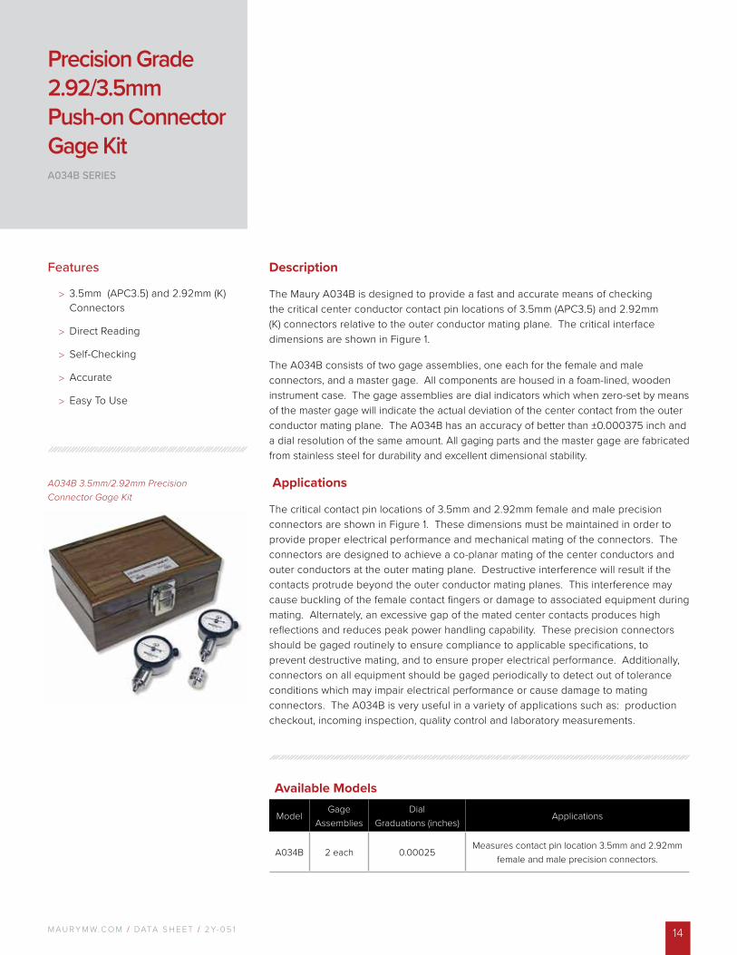
The Maury A034B is designed to provide a fast and accurate means of checking the critical center conductor contact pin locations of 3.5mm (APC3.5) and 2.92mm (K) connectors relative to the outer conductor mating plane. The critical interface dimensions are shown in Figure 1.
The A034B consists of two gage assemblies, one each for the female and male connectors, and a master gage. All components are housed in a foam-lined, wooden instrument case. The gage assemblies are dial indicators which when zero-set by means of the master gage will indicate the actual deviation of the center contact from the outer conductor mating plane. The A034B has an accuracy of better than ±0.000375 inch and a dial resolution of the same amount. All gaging parts and the master gage are fabricated from stainless steel for durability and excellent dimensional stability.
Applications
The critical contact pin locations of 3.5mm and 2.92mm female and male precision connectors are shown in Figure 1. These dimensions must be maintained in order to provide proper electrical performance and mechanical mating of the connectors. The connectors are designed to achieve a co-planar mating of the center conductors and outer conductors at the outer mating plane. Destructive interference will result if the contacts protrude beyond the outer conductor mating planes. This interference may cause buckling of the female contact fingers or damage to associated equipment during mating. Alternately, an excessive gap of the mated center contacts produces high reflections and reduces peak power handling capability. These precision connectors should be gaged routinely to ensure compliance to applicable specifications, to prevent destructive mating, and to ensure proper electrical performance. Additionally, connectors on all equipment should be gaged periodically to detect out of tolerance conditions which may impair electrical performance or cause damage to mating connectors. The A034B is very useful in a variety of applications such as: production checkout, incoming inspection, quality control and laboratory measurements.
Features
> 3.5mm (APC3.5) and 2.92mm (K) Connectors
> Direct Reading
> Self-Checking
> Accurate
> Easy To Use
Precision Grade 2.92/3.5mm Push-on Connector Gage KitA034B SERIES
Available Models
ModelGage
AssembliesDial
Graduations (inches)Applications
A034B 2 each 0.00025Measures contact pin location 3.5mm and 2.92mm
female and male precision connectors.
M AU R Y M W. C O M / DATA S H E E T / 2 Y- 0 5 115
2
1
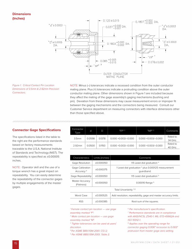
Figure 1. Critical Contact Pin Location Dimensions of 3.5mm & 2.92mm Precision Connectors.
Dimensions (Inches)
Connector Gage Specifications
The specifications listed in the table to the right are the performance standards based on factory measurements traceable to the U.S.A. National Institute of Standards and Technology (NIST). The repeatability is specified as ±0.00005 inches.
NOTE: Operator skill and the use of a torque wrench has a great impact on repeatability. You can easily determine the repeatability of the connector gages by multiple engagements of the master gages.
1 Female contact pin location — use gage assembly marked "F".2 Male contact pin location — use gage assembly marked "M".3 Tighter tolerances can be used at users' discretion. 4 Per ASME B89.1.10M-2001, C5.1.2.5 Per ASME B89.1.10M-2001, Table 2.
6 Per manufacturer's specification.7 Performance standards are in compliance with ANSI/NCSL Z540-1, MIL-STD-45662A and ISO 10012-1.8 Applies over the operating range for connector gaging 0.006" recession to 0.003" protrusion from master gage zero setting.
Characteristics Limits (inches) Comments
Gage Resolution ±0.000050 1/5 Least dial graduation 4
Gage Calibration Accuracy 9 ±0.000375
1 Least dial graduation 5 plus 0.000125 measurement guardband.
Gage Repeatability ±0.000050 1/5 Least dial graduation 5
Master Accuracy (Flatness)
±0.000050 0.00010 Range 6
Total Uncertainty 7, 8
Worst Case ±0.000525 Add resolution, repeatability, gage and master accuracy limits.
RSS ±0.000385 Root sum of the squares.
NOTE: Minus (–) tolerances indicate a recessed condition from the outer conductor mating plane. Plus (+) tolerances indicate a protruding condition above the outer conductor mating plane. Other dimensions shown in Figure 1 are included because they affect the mating of the gage assembly's gaging mechanisms (bushing and pin). Deviation from these dimensions may cause measurement errors or improper fit between the gaging mechanisms and the connectors being measured. Consult our Customer Service department on measuring connectors with interface dimensions other than those specified above.
Connector Type
d D "FP" 3 "MP" 3 Comments
3.5mm 0.0598 0.1378 0.000 +0.003/–0.000 0.000 +0.003/–0.000Rated to 34 GHz.
2.92mm 0.0500 0.1150 0.000 +0.003/–0.000 0.000 +0.003/–0.000Rated to 40 GHz.
M AU R Y M W. C O M / DATA S H E E T / 2 Y- 0 5 1 16
A034E 3.5mm/2.92mm Precision Connector Gage Kit
Description
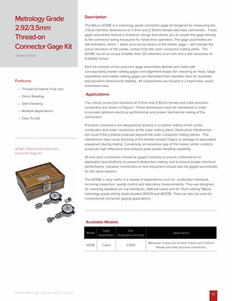
The Maury A034E is a metrology grade connector gage kit designed for measuring the critical interface dimensions of 3.5mm and 2.92mm female and male connectors. These gage assemblies feature a thread-on design that allows you to couple the gage directly to the connector being measured for hands free operation. The gage assemblies are dial indicators, which – when zero-set by means of the master gage – will indicate the actual deviation of the center contact from the outer conductor mating plane. The A034E has an accuracy of better than 20 millionths of an inch and a dial resolution of 0.00002 inches.
Each kit consists of two precision gage assemblies (female and male) with corresponding master setting gages and alignment beads (for checking air lines). Gage assemblies and master setting gages are fabricated from stainless steel for durability and excellent dimensional stability. All components are housed in a foam-lined, wood instrument case.
Applications
The critical contact pin locations of 3.5mm and 2.92mm female and male precision connectors are shown in Figure 1. These dimensions must be maintained in order to provide optimum electrical performance and proper mechanical mating of the connectors.
Precision connectors are designed to achieve a co-planar mating of the center conductors and outer conductors at the outer mating plane. Destructive interference will result if the contacts protrude beyond the outer conductor mating planes. This interference may cause buckling of the female contact fingers or damage to associated equipment during mating. Conversely, an excessive gap of the mated center contacts produces high reflections and reduces peak power handling capability.
All precision connectors should be gaged routinely to ensure conformance to applicable specifications, to prevent destructive mating, and to ensure proper electrical performance. Likewise, connectors on test equipment should also be gaged periodically for the same reasons.
The A034E is very useful in a variety of applications such as: production checkout, incoming inspection, quality control and laboratory measurements. They are designed for checking beadless air line interfaces, VNA test ports and for "flush setting" Maury metrology grade sliding loads (models 8037A and 8037B). They can also be used for conventional connector gaging applications.
Features
> Thread-On Hands Free Use
> Direct Reading
> Self-Checking
> Multiple Applications
> Easy To Use
Metrology Grade 2.92/3.5mm Thread-on Connector Gage KitA034E SERIES
Available Models
ModelGage
AssembliesDial
Graduations (inches)Applications
A034E 2 each 0.0001Measures contact pin location 3.5mm and 2.92mm
female and male precision connectors.
M AU R Y M W. C O M / DATA S H E E T / 2 Y- 0 5 117
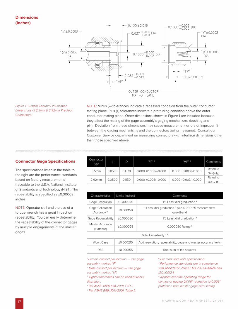
Figure 1. Critical Contact Pin Location Dimensions of 3.5mm & 2.92mm Precision Connectors.
Dimensions (Inches)
Connector Gage Specifications
The specifications listed in the table to the right are the performance standards based on factory measurements traceable to the U.S.A. National Institute of Standards and Technology (NIST). The repeatability is specified as ±0.00002 inches.
NOTE: Operator skill and the use of a torque wrench has a great impact on repeatability. You can easily determine the repeatability of the connector gages by multiple engagements of the master gages.
1 Female contact pin location — use gage assembly marked "F".2 Male contact pin location — use gage assembly marked "M".3 Tighter tolerances can be used at users' discretion. 4 Per ASME B89.1.10M-2001, C5.1.2.5 Per ASME B89.1.10M-2001, Table 2.
6 Per manufacturer's specification.7 Performance standards are in compliance with ANSI/NCSL Z540-1, MIL-STD-45662A and ISO 10012-1.8 Applies over the operating range for connector gaging 0.006" recession to 0.003" protrusion from master gage zero setting.
Characteristics Limits (inches) Comments
Gage Resolution ±0.000020 1/5 Least dial graduation 4
Gage Calibration Accuracy 9 ±0.000150
1 Least dial graduation 5 plus 0.000125 measurement guardband.
Gage Repeatability ±0.000020 1/5 Least dial graduation 5
Master Accuracy (Flatness)
±0.000025 0.000050 Range 6
Total Uncertainty 7, 8
Worst Case ±0.000215 Add resolution, repeatability, gage and master accuracy limits.
RSS ±0.000155 Root sum of the squares.
NOTE: Minus (–) tolerances indicate a recessed condition from the outer conductor mating plane. Plus (+) tolerances indicate a protruding condition above the outer conductor mating plane. Other dimensions shown in Figure 1 are included because they affect the mating of the gage assembly's gaging mechanisms (bushing and pin). Deviation from these dimensions may cause measurement errors or improper fit between the gaging mechanisms and the connectors being measured. Consult our Customer Service department on measuring connectors with interface dimensions other than those specified above.
Connector Type
d D "FP" 3 "MP" 3 Comments
3.5mm 0.0598 0.1378 0.000 +0.003/–0.000 0.000 +0.003/–0.000Rated to 34 GHz.
2.92mm 0.0500 0.1150 0.000 +0.003/–0.000 0.000 +0.003/–0.000Rated to 40 GHz.
2
1
M AU R Y M W. C O M / DATA S H E E T / 2 Y- 0 5 1 18
A035E 1.85mm/2.4mm Metrology Grade Connector Gage Kit
Description
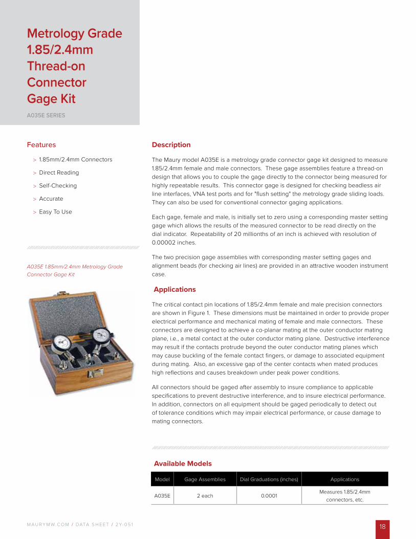
The Maury model A035E is a metrology grade connector gage kit designed to measure 1.85/2.4mm female and male connectors. These gage assemblies feature a thread-on design that allows you to couple the gage directly to the connector being measured for highly repeatable results. This connector gage is designed for checking beadless air line interfaces, VNA test ports and for "flush setting" the metrology grade sliding loads. They can also be used for conventional connector gaging applications.
Each gage, female and male, is initially set to zero using a corresponding master setting gage which allows the results of the measured connector to be read directly on the dial indicator. Repeatability of 20 millionths of an inch is achieved with resolution of 0.00002 inches.
The two precision gage assemblies with corresponding master setting gages and alignment beads (for checking air lines) are provided in an attractive wooden instrument case.
Applications
The critical contact pin locations of 1.85/2.4mm female and male precision connectors are shown in Figure 1. These dimensions must be maintained in order to provide proper electrical performance and mechanical mating of female and male connectors. These connectors are designed to achieve a co-planar mating at the outer conductor mating plane, i.e., a metal contact at the outer conductor mating plane. Destructive interference may result if the contacts protrude beyond the outer conductor mating planes which may cause buckling of the female contact fingers, or damage to associated equipment during mating. Also, an excessive gap of the center contacts when mated produces high reflections and causes breakdown under peak power conditions.
All connectors should be gaged after assembly to insure compliance to applicable specifications to prevent destructive interference, and to insure electrical performance. In addition, connectors on all equipment should be gaged periodically to detect out of tolerance conditions which may impair electrical performance, or cause damage to mating connectors.
Features
> 1.85mm/2.4mm Connectors
> Direct Reading
> Self-Checking
> Accurate
> Easy To Use
Metrology Grade 1.85/2.4mm Thread-on Connector Gage KitA035E SERIES
Available Models
Model Gage Assemblies Dial Graduations (inches) Applications
A035E 2 each 0.0001Measures 1.85/2.4mm
connectors, etc.
M AU R Y M W. C O M / DATA S H E E T / 2 Y- 0 5 119
2, 3 1, 3
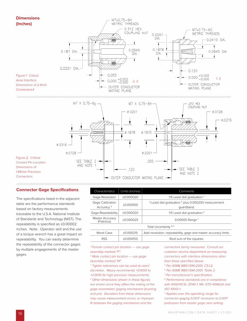
Figure 1 Critical Axial Interface Dimensions of 2.4mm Connectors4
Dimensions (Inches)
Connector Gage Specifications
The specifications listed in the adjacent table are the performance standards based on factory measurements traceable to the U.S.A. National Institute of Standards and Technology (NIST). The repeatability is specified as ±0.00002 inches. Note: Operator skill and the use of a torque wrench has a great impact on repeatability. You can easily determine the repeatability of the connector gages by multiple engagements of the master gages.
1 Female contact pin location — use gage assembly marked "F".2 Male contact pin location — use gage assembly marked "M".3 Tighter tolerances can be used at users' discretion. Maury recommends +0.0001 to +0.0015 for high precision measurements.4 Other dimensions shown in these figures are shown since they affect the mating of the gage assemblies' gaging mechanism (bushing and pin). Deviation from these dimensions may cause measurement errors, or improper fit between the gaging mechanism and the
connectors being measured. Consult our customer service department on measuring connectors with interface dimensions other than those specified above. 5 Per ASME B89.1.10M-2001, C5.1.2.6 Per ASME B89.1.10M-2001, Table 2.7 Per manufacturer's specification.8 Performance standards are in compliance with ANSI/NCSL Z540-1, MIL-STD-45662A and ISO 10012-1.9 Applies over the operating range for connector gaging 0.003" recession to 0.001" protrusion from master gage zero setting.
Characteristics Limits (inches) Comments
Gage Resolution ±0.000020 1/5 Least dial graduation 5
Gage Calibration Accuracy 9 ±0.000150
1 Least dial graduation 6 plus 0.000250 measurement guardband.
Gage Repeatability ±0.000020 1/5 Least dial graduation 6
Master Accuracy (Flatness) ±0.000025 0.00005 Range 7
Total Uncertainty 8, 9
Worst Case ±0.000215 Add resolution, repeatability, gage and master accuracy limits.
RSS ±0.000155 Root sum of the squares.
Figure 2. Critical Contact Pin Location Dimensions of 1.85mm Precision Connectors
M AU R Y M W. C O M / DATA S H E E T / 2 Y- 0 5 1 20
A028D Metrology Grade7mm Precision Connector Gage Kit
Description
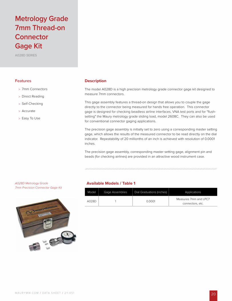
The model A028D is a high precision metrology grade connector gage kit designed to measure 7mm connectors.
This gage assembly features a thread-on design that allows you to couple the gage directly to the connector being measured for hands free operation. This connector gage is designed for checking beadless airline interfaces, VNA test ports and for "flush-setting" the Maury metrology grade sliding load, model 2608C. They can also be used for conventional connector gaging applications.
The precision gage assembly is initially set to zero using a corresponding master setting gage, which allows the results of the measured connector to be read directly on the dial indicator. Repeatability of 20 millionths of an inch is achieved with resolution of 0.0001 inches.
The precision gage assembly, corresponding master setting gage, alignment pin and beads (for checking airlines) are provided in an attractive wood instrument case.
Features
> 7mm Connectors
> Direct Reading
> Self-Checking
> Accurate
> Easy To Use
Metrology Grade 7mm Thread-on Connector Gage KitA028D SERIES
Available Models / Table 1
Model Gage Assemblies Dial Graduations (inches) Applications
A028D 1 0.0001Measures 7mm and LPC7
connectors, etc.
M AU R Y M W. C O M / DATA S H E E T / 2 Y- 0 5 121
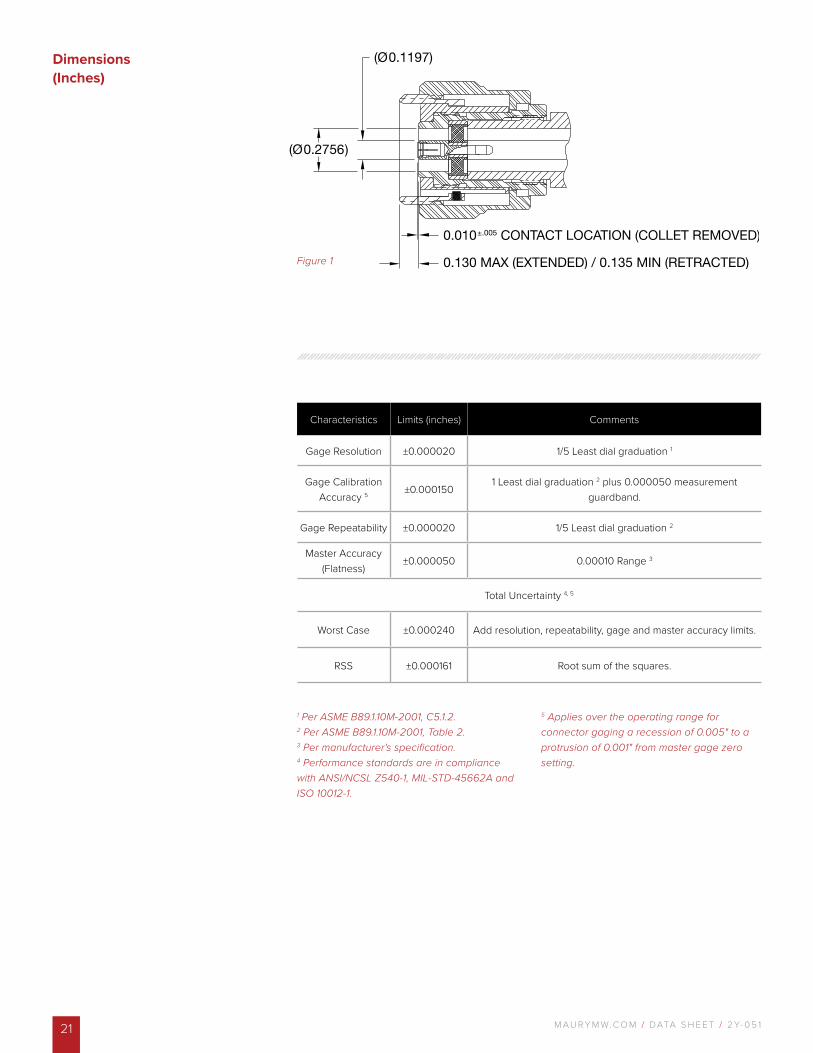
Figure 1
Dimensions (Inches)
1 Per ASME B89.1.10M-2001, C5.1.2. 2 Per ASME B89.1.10M-2001, Table 2.3 Per manufacturer's specification. 4 Performance standards are in compliance with ANSI/NCSL Z540-1, MIL-STD-45662A and ISO 10012-1.
5 Applies over the operating range for connector gaging a recession of 0.005" to a protrusion of 0.001" from master gage zero setting.
Characteristics Limits (inches) Comments
Gage Resolution ±0.000020 1/5 Least dial graduation 1
Gage Calibration Accuracy 5 ±0.000150
1 Least dial graduation 2 plus 0.000050 measurement guardband.
Gage Repeatability ±0.000020 1/5 Least dial graduation 2
Master Accuracy (Flatness)
±0.000050 0.00010 Range 3
Total Uncertainty 4, 5
Worst Case ±0.000240 Add resolution, repeatability, gage and master accuracy limits.
RSS ±0.000161 Root sum of the squares.
M AU R Y M W. C O M / DATA S H E E T / 2 Y- 0 5 1 22
A007A Type N Dial Indicator Precision Connector Gage Kit
* Refer to data sheet 2Y-003 regarding the availability of additional master gages.
Description
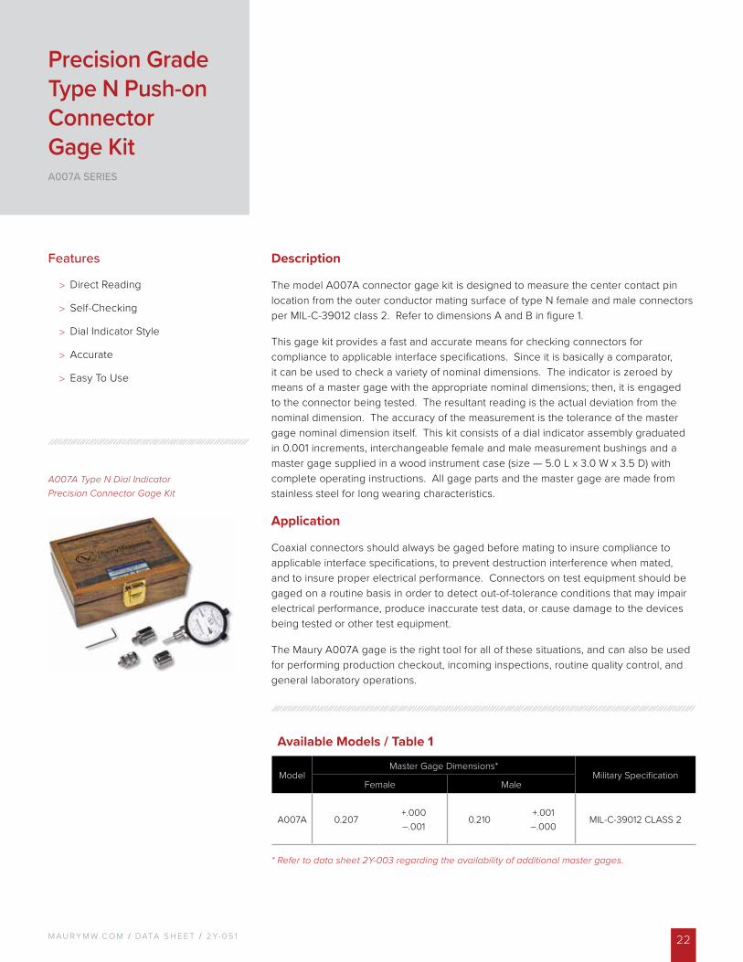
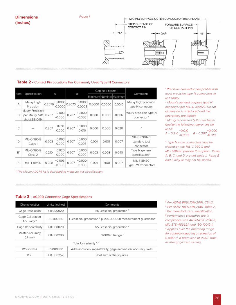
The model A007A connector gage kit is designed to measure the center contact pin location from the outer conductor mating surface of type N female and male connectors per MIL-C-39012 class 2. Refer to dimensions A and B in figure 1.
This gage kit provides a fast and accurate means for checking connectors for compliance to applicable interface specifications. Since it is basically a comparator, it can be used to check a variety of nominal dimensions. The indicator is zeroed by means of a master gage with the appropriate nominal dimensions; then, it is engaged to the connector being tested. The resultant reading is the actual deviation from the nominal dimension. The accuracy of the measurement is the tolerance of the master gage nominal dimension itself. This kit consists of a dial indicator assembly graduated in 0.001 increments, interchangeable female and male measurement bushings and a master gage supplied in a wood instrument case (size — 5.0 L x 3.0 W x 3.5 D) with complete operating instructions. All gage parts and the master gage are made from stainless steel for long wearing characteristics.
Application
Coaxial connectors should always be gaged before mating to insure compliance to applicable interface specifications, to prevent destruction interference when mated, and to insure proper electrical performance. Connectors on test equipment should be gaged on a routine basis in order to detect out-of-tolerance conditions that may impair electrical performance, produce inaccurate test data, or cause damage to the devices being tested or other test equipment.
The Maury A007A gage is the right tool for all of these situations, and can also be used for performing production checkout, incoming inspections, routine quality control, and general laboratory operations.
Features
> Direct Reading
> Self-Checking
> Dial Indicator Style
> Accurate
> Easy To Use
Precision Grade Type N Push-on Connector Gage KitA007A SERIES
Available Models / Table 1
ModelMaster Gage Dimensions*
Military SpecificationFemale Male
A007A 0.207+.000–.001
0.210+.001–.000
MIL-C-39012 CLASS 2
M AU R Y M W. C O M / DATA S H E E T / 2 Y- 0 5 123
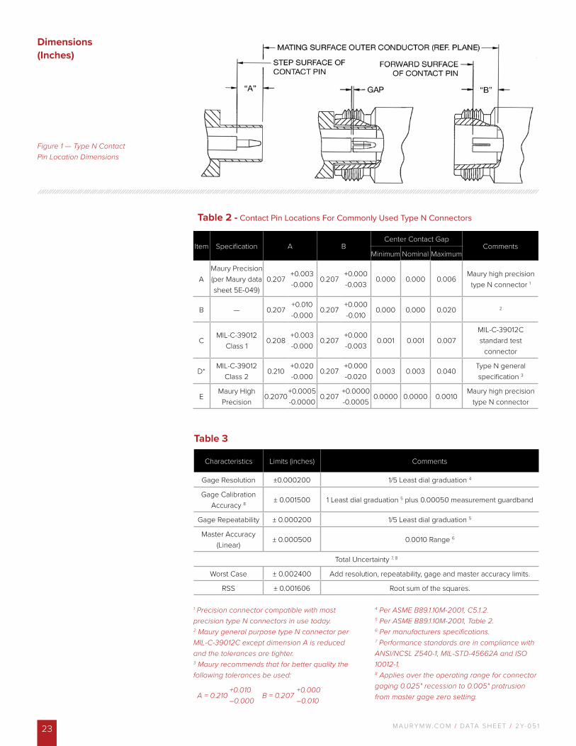
Figure 1 — Type N Contact Pin Location Dimensions
Table 2 - Contact Pin Locations For Commonly Used Type N Connectors
Item Specification A BCenter Contact Gap
CommentsMinimum Nominal Maximum
AMaury Precision (per Maury data sheet 5E-049)
0.207+0.003-0.000
0.207+0.000-0.003
0.000 0.000 0.006Maury high precision
type N connector 1
B — 0.207+0.010-0.000
0.207+0.000-0.010
0.000 0.000 0.020 2
CMIL-C-39012
Class 10.208
+0.003-0.000
0.207+0.000-0.003
0.001 0.001 0.007MIL-C-39012C standard test
connector
D*MIL-C-39012
Class 20.210
+0.020-0.000
0.207+0.000-0.020
0.003 0.003 0.040Type N general specification 3
EMaury HighPrecision
0.2070+0.0005 -0.0000
0.207+0.0000 -0.0005
0.0000 0.0000 0.0010Maury high precision
type N connector
Dimensions (Inches)
1 Precision connector compatible with most precision type N connectors in use today.2 Maury general purpose type N connector per MIL-C-39012C except dimension A is reduced and the tolerances are tighter. 3 Maury recommends that for better quality the following tolerances be used:
4 Per ASME B89.1.10M-2001, C5.1.2. 5 Per ASME B89.1.10M-2001, Table 2.6 Per manufacturers specifications.7 Performance standards are in compliance with ANSI/NCSL Z540-1, MIL-STD-45662A and ISO 10012-1.8 Applies over the operating range for connector gaging 0.025" recession to 0.005" protrusion from master gage zero setting.
Table 3
Characteristics Limits (inches) Comments
Gage Resolution ±0.000200 1/5 Least dial graduation 4
Gage Calibration Accuracy 8 ± 0.001500 1 Least dial graduation 5 plus 0.00050 measurement guardband
Gage Repeatability ± 0.000200 1/5 Least dial graduation 5
Master Accuracy (Linear)
± 0.000500 0.0010 Range 6
Total Uncertainty 7, 8
Worst Case ± 0.002400 Add resolution, repeatability, gage and master accuracy limits.
RSS ± 0.001606 Root sum of the squares.
A = 0.210 B = 0.207+0.010–0.000
+0.000–0.010
M AU R Y M W. C O M / DATA S H E E T / 2 Y- 0 5 1 24
Specifications
Connectors Measured -- Precision N, female and maleInterface Specifications:
MIL-C-39012 (Standard Test Connector) MIL-T-81490 and Maury Precision Type N (5E-049)
Dial Indicator -- 2-1/4 dia. (0.00025 Graduations)Master Gage Dimensions -- 0.207 female and maleAccuracy of Measurement (*) -- Refer to Table 3Case Dimensions (inches) -- 6.0 L x 4.0 W x 2.0 D
(*) Applies to S/N 2586 and on.
A020A Type N Precision Connector Gage Kit
Description
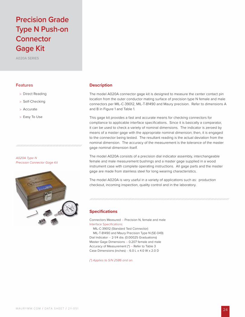
The model A020A connector gage kit is designed to measure the center contact pin location from the outer conductor mating surface of precision type N female and male connectors per MIL-C-39012, MIL-T-81490 and Maury precision. Refer to dimensions A and B in Figure 1 and Table 1.
This gage kit provides a fast and accurate means for checking connectors for compliance to applicable interface specifications. Since it is basically a comparator, it can be used to check a variety of nominal dimensions. The indicator is zeroed by means of a master gage with the appropriate nominal dimension; then, it is engaged to the connector being tested. The resultant reading is the actual deviation from the nominal dimension. The accuracy of the measurement is the tolerance of the master gage nominal dimension itself.
The model A020A consists of a precision dial indicator assembly, interchangeable female and male measurement bushings and a master gage supplied in a wood instrument case with complete operating instructions. All gage parts and the master gage are made from stainless steel for long wearing characteristics.
The model A020A is very useful in a variety of applications such as: production checkout, incoming inspection, quality control and in the laboratory.
Features
> Direct Reading
> Self-Checking
> Accurate
> Easy To Use
Precision Grade Type N Push-on Connector Gage KitA020A SERIES
M AU R Y M W. C O M / DATA S H E E T / 2 Y- 0 5 125
Options And Accessories
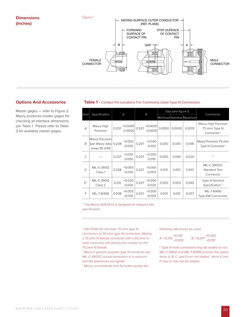
Master gages — refer to Figure 2. Maury produces master gages for checking all interface dimensions per Table 1. Please refer to Table 2 for available master gages.
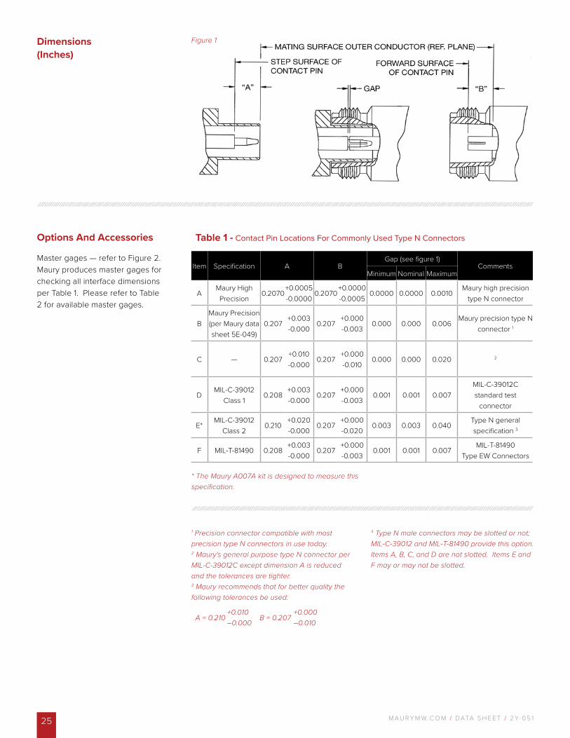
Figure 1
Table 1 - Contact Pin Locations For Commonly Used Type N Connectors
Item Specification A BGap (see figure 1)
CommentsMinimum Nominal Maximum
AMaury High Precision
0.2070+0.0005-0.0000
0.2070+0.0000-0.0005
0.0000 0.0000 0.0010Maury high precision
type N connector
BMaury Precision (per Maury data sheet 5E-049)
0.207+0.003-0.000
0.207+0.000-0.003
0.000 0.000 0.006Maury precision type N
connector 1
C — 0.207+0.010-0.000
0.207+0.000-0.010
0.000 0.000 0.020 2
DMIL-C-39012
Class 10.208
+0.003-0.000
0.207+0.000-0.003
0.001 0.001 0.007MIL-C-39012C standard test
connector
E*MIL-C-39012
Class 20.210
+0.020 -0.000
0.207+0.000-0.020
0.003 0.003 0.040Type N general specification 3
F MIL-T-81490 0.208+0.003-0.000
0.207+0.000-0.003
0.001 0.001 0.007MIL-T-81490
Type EW Connectors
Dimensions (Inches)
1 Precision connector compatible with most precision type N connectors in use today. 2 Maury's general purpose type N connector per MIL-C-39012C except dimension A is reduced and the tolerances are tighter.3 Maury recommends that for better quality the following tolerances be used:
4 Type N male connectors may be slotted or not; MIL-C-39012 and MIL-T-81490 provide this option. Items A, B, C, and D are not slotted. Items E and F may or may not be slotted.
A = 0.210 B = 0.207+0.010–0.000
+0.000–0.010
* The Maury A007A kit is designed to measure this specification.
M AU R Y M W. C O M / DATA S H E E T / 2 Y- 0 5 1 26
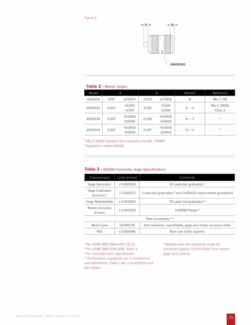
Figure 2
Table 2 - Master Gages
Model A B Marked Reference
A005S31 0.197 ±0.0005 0.223 ±0.0005 N MIL-C-71B
A005S32 0.207+0.000-0.001
0.210+0.001-0.000
N — 2MIL-C-39012
Class 2
A005S34 0.207+0.0000-0.0005
0.208+0.0005-0.0000
N — 3 5
A005S35 0.207+0.0000-0.0005
0.207+0.0005-0.0000
N — 4 6
7 Per ASME B89.1.10M-2001, C5.1.2. 8 Per ASME B89.1.10M-2001, Table 2.9 Per manufacturer's specification. 10 Performance standards are in compliance with ANSI/NCSL Z540-1, MIL-STD-45662A and ISO 10012-1.
11 Applies over the operating range for connector gaging +0.011/-0.001" from master gage zero setting.
5 MIL-C-39012 standard test connector and MIL-T-81490. 6 Supplied in model A020A.
Table 3 - A020A Connector Gage Specifications
Characteristics Limits (inches) Comments
Gage Resolution ± 0.000050 1/5 Least dial graduation 7
Gage Calibration Accuracy 11 ± 0.000375 1 Least dial graduation 8 plus 0.000125 measurement guardband
Gage Repeatability ± 0.000050 1/5 Least dial graduation 8
Master Accuracy (Linear)
± 0.000250 0.00050 Range 9
Total Uncertainty 10, 11
Worst Case ±0.000725 Add resolution, repeatability, gage and master accuracy limits.
RSS ± 0.000456 Root sum of the squares.
M AU R Y M W. C O M / DATA S H E E T / 2 Y- 0 5 127
A020D Metrology GradeType N PrecisionConnector Gage Kit
Description
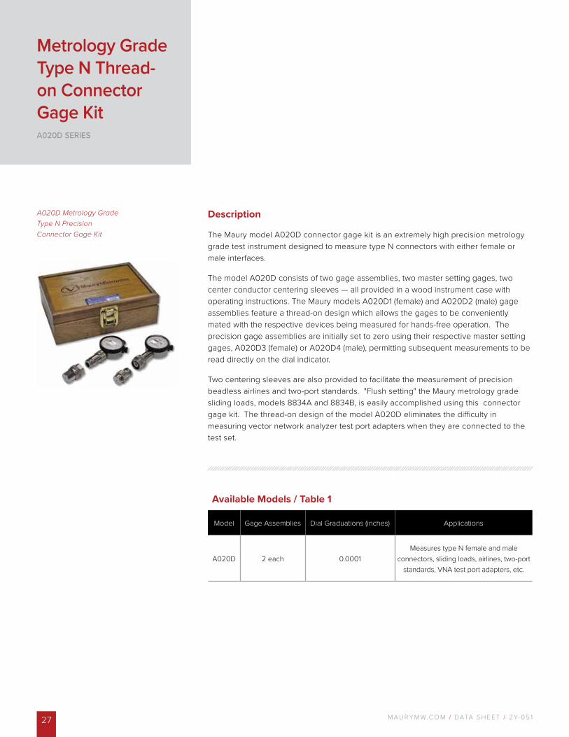
The Maury model A020D connector gage kit is an extremely high precision metrology grade test instrument designed to measure type N connectors with either female or male interfaces.
The model A020D consists of two gage assemblies, two master setting gages, two center conductor centering sleeves — all provided in a wood instrument case with operating instructions. The Maury models A020D1 (female) and A020D2 (male) gage assemblies feature a thread-on design which allows the gages to be conveniently mated with the respective devices being measured for hands-free operation. The precision gage assemblies are initially set to zero using their respective master setting gages, A020D3 (female) or A020D4 (male), permitting subsequent measurements to be read directly on the dial indicator.
Two centering sleeves are also provided to facilitate the measurement of precision beadless airlines and two-port standards. "Flush setting" the Maury metrology grade sliding loads, models 8834A and 8834B, is easily accomplished using this connector gage kit. The thread-on design of the model A020D eliminates the difficulty in measuring vector network analyzer test port adapters when they are connected to the test set.
Metrology Grade Type N Thread-on Connector Gage KitA020D SERIES
Available Models / Table 1
Model Gage Assemblies Dial Graduations (inches) Applications
A020D 2 each 0.0001Measures type N female and male
connectors, sliding loads, airlines, two-port standards, VNA test port adapters, etc.
M AU R Y M W. C O M / DATA S H E E T / 2 Y- 0 5 1 28
Figure 1
* The Maury A007A kit is designed to measure this specification.
Table 3 - A020D Connector Gage Specifications
Characteristics Limits (inches) Comments
Gage Resolution ± 0.000020 1/5 Least dial graduation 5
Gage Calibration Accuracy 9 ± 0.000150 1 Least dial graduation 6 plus 0.000050 measurement guardband
Gage Repeatability ± 0.000020 1/5 Least dial graduation 6
Master Accuracy (Linear)
± 0.000200 0.00040 Range 7
Total Uncertainty 8, 9
Worst Case ±0.000390 Add resolution, repeatability, gage and master accuracy limits.
RSS ± 0.000252 Root sum of the squares.
5 Per ASME B89.1.10M-2001, C5.1.2. 6 Per ASME B89.1.10M-2001, Table 2.7 Per manufacturer's specification. 8 Performance standards are in compliance with ANSI/NCSL Z540-1, MIL-STD-45662A and ISO 10012-1.9 Applies over the operating range for connector gaging a recession of 0.005" to a protrusion of 0.001" from master gage zero setting.
1 Precision connector compatible with most precision type N connectors in use today. 2 Maury's general purpose type N connector per MIL-C-39012C except dimension A is reduced and the tolerances are tighter.3 Maury recommends that for better quality the following tolerances be used: A = 0.210 B = 0.207
4 Type N male connectors may be slotted or not; MIL-C-39012 and MIL-T-81490 provide this option. Items A, B, C, and D are not slotted. Items E and F may or may not be slotted.
+0.010-0.000
+0.000-0.010
Table 2 - Contact Pin Locations For Commonly Used Type N Connectors
Item Specification A BGap (see figure 1)
CommentsMinimum Nominal Maximum
AMaury High Precision
0.2070+0.0005-0.0000
0.2070+0.0000-0.0005
0.0000 0.0000 0.0010Maury high precision
type N connector
BMaury Precision (per Maury data sheet 5E-049)
0.207+0.003-0.000
0.207+0.000-0.003
0.000 0.000 0.006Maury precision type N
connector 1
C — 0.207+0.010-0.000
0.207+0.000-0.010
0.000 0.000 0.020 2
DMIL-C-39012
Class 10.208
+0.003-0.000
0.207+0.000-0.003
0.001 0.001 0.007MIL-C-39012C standard test
connector
E*MIL-C-39012
Class 20.210
+0.020 -0.000
0.207+0.000-0.020
0.003 0.003 0.040Type N general specification 3
F MIL-T-81490 0.208+0.003-0.000
0.207+0.000-0.003
0.001 0.001 0.007MIL-T-81490
Type EW Connectors
Dimensions (Inches)
M AU R Y M W. C O M / DATA S H E E T / 2 Y- 0 5 129
Description
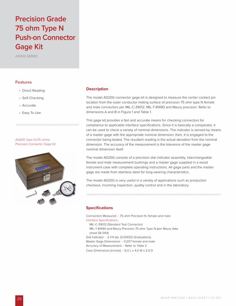
The model A020G connector gage kit is designed to measure the center contact pin location from the outer conductor mating surface of precision 75 ohm type N female and male connectors per MIL-C-39012, MIL-T-81490 and Maury precision. Refer to dimensions A and B in Figure 1 and Table 1.
This gage kit provides a fast and accurate means for checking connectors for compliance to applicable interface specifications. Since it is basically a comparator, it can be used to check a variety of nominal dimensions. The indicator is zeroed by means of a master gage with the appropriate nominal dimension; then, it is engaged to the connector being tested. The resultant reading is the actual deviation from the nominal dimension. The accuracy of the measurement is the tolerance of the master gage nominal dimension itself.
The model A020G consists of a precision dial indicator assembly, interchangeable female and male measurement bushings and a master gage supplied in a wood instrument case with complete operating instructions. All gage parts and the master gage are made from stainless steel for long wearing characteristics.
The model A020G is very useful in a variety of applications such as production checkout, incoming inspection, quality control and in the laboratory.
Precision Grade 75 ohm Type N Push-on Connector Gage KitA020G SERIES
A020G Type N (75 ohms) Precision Connector Gage Kit
Features
> Direct Reading
> Self-Checking
> Accurate
> Easy To Use
Specifications
Connectors Measured -- 75 ohm Precision N, female and maleInterface Specifications:
MIL-C-39012 (Standard Test Connector) MIL-T-81490 and Maury Precision 75 ohm Type N (per Maury data sheet 5E-054)
Dial Indicator -- 2-1/4 dia. (0.00025 Graduations)Master Gage Dimensions -- 0.207 female and maleAccuracy of Measurement -- Refer to Table 3Case Dimensions (inches) -- 6.0 L x 4.0 W x 2.0 D
M AU R Y M W. C O M / DATA S H E E T / 2 Y- 0 5 1 30
Options And Accessories
Master gages — refer to Figure 2. Maury produces master gages for checking all interface dimensions per Table 1. Please refer to Table 2 for available master gages.
Figure 1
Table 1 - Contact Pin Locations For Commonly Used Type N Connectors
Item Specification A BGap (see figure 1)
CommentsMinimum Nominal Maximum
AMaury High Precision
0.207+0.0005-0.0000
0.207+0.0000-0.0005
0.0000 0.0000 0.0010Maury High Precision
75 ohm Type N Connector 1
BMaury Precision (per Maury data sheet 5E-049)
0.208+0.003-0.000
0.207+0.000-0.003
0.000 0.000 0.006Maury Precision 75 ohm
Type N Connector 1
C — 0.207+0.010-0.000
0.207+0.000-0.010
0.000 0.000 0.020 2
DMIL-C-39012
Class 10.208
+0.003-0.000
0.207+0.000-0.003
0.001 0.001 0.007MIL-C-39012C Standard Test
Connector
E*MIL-C-39012
Class 20.210
+0.020 -0.000
0.207+0.000-0.020
0.003 0.003 0.040Type N GeneralSpecification 3
F MIL-T-81490 0.208+0.003-0.000
0.207+0.000-0.003
0.001 0.001 0.007MIL-T-81490
Type EW Connectors
1 CAUTION! Do not mate 75 ohm type N connectors to 50 ohm type N connectors. Mating a 75 ohm N female connector with a 50 ohm N male connector will destroy the contact on the 75 ohm N female. 2 Maury's general purpose type N connector per MIL-C-39012C except dimension A is reduced and the tolerances are tighter.3 Maury recommends that for better quality the
following tolerances be used:
A = 0.210 B = 0.207
4 Type N male connectors may be slotted or not; MIL-C-39012 and MIL-T-81490 provide this option. Items A, B, C, and D are not slotted. Items E and F may or may not be slotted.
+0.010–0.000
+0.000–0.010
* The Maury A007A kit is designed to measure this specification.
Dimensions (Inches)
M AU R Y M W. C O M / DATA S H E E T / 2 Y- 0 5 131
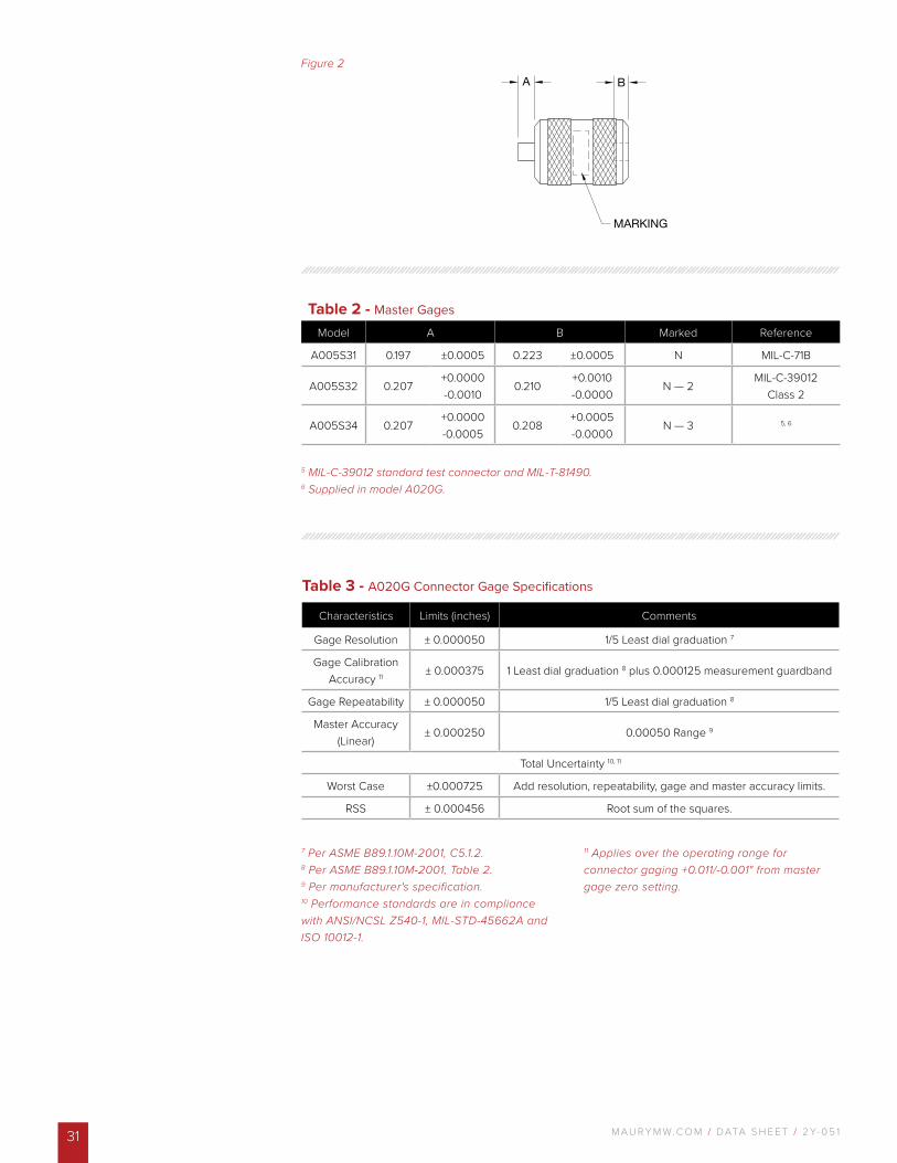
Figure 2
Table 2 - Master Gages
Model A B Marked Reference
A005S31 0.197 ±0.0005 0.223 ±0.0005 N MIL-C-71B
A005S32 0.207+0.0000-0.0010
0.210+0.0010-0.0000
N — 2MIL-C-39012
Class 2
A005S34 0.207+0.0000-0.0005
0.208+0.0005-0.0000
N — 3 5, 6
7 Per ASME B89.1.10M-2001, C5.1.2. 8 Per ASME B89.1.10M-2001, Table 2.9 Per manufacturer's specification. 10 Performance standards are in compliance with ANSI/NCSL Z540-1, MIL-STD-45662A and ISO 10012-1.
11 Applies over the operating range for connector gaging +0.011/-0.001" from master gage zero setting.
5 MIL-C-39012 standard test connector and MIL-T-81490. 6 Supplied in model A020G.
Table 3 - A020G Connector Gage Specifications
Characteristics Limits (inches) Comments
Gage Resolution ± 0.000050 1/5 Least dial graduation 7
Gage Calibration Accuracy 11 ± 0.000375 1 Least dial graduation 8 plus 0.000125 measurement guardband
Gage Repeatability ± 0.000050 1/5 Least dial graduation 8
Master Accuracy (Linear)
± 0.000250 0.00050 Range 9
Total Uncertainty 10, 11
Worst Case ±0.000725 Add resolution, repeatability, gage and master accuracy limits.
RSS ± 0.000456 Root sum of the squares.
M AU R Y M W. C O M / DATA S H E E T / 2 Y- 0 5 1 32
Specifications
Connectors Measured -- TNC and BNC, female & maleInterface Specifications:
MIL-C-87104/2 (AFTNC Connectors) MIL-STD-384A (TNCA Connectors)MIL-T-81490IEC 169-17IEC 169-26
Dial Indicator -- 2-1/4 dia. (0.000100 Graduations)Master Gage Dimensions -- 0.207 female and maleAccuracy of Measurement -- Refer to Table 2Case Dimensions (inches) -- 6.0 L x 4.0 W x 2.0 D
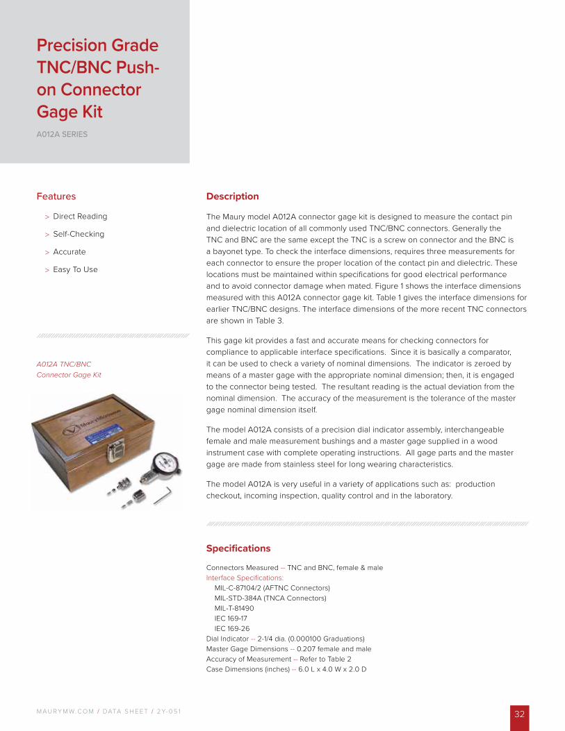
A012A TNC/BNC Connector Gage Kit
Description
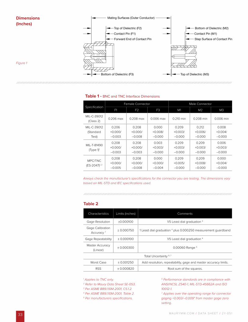
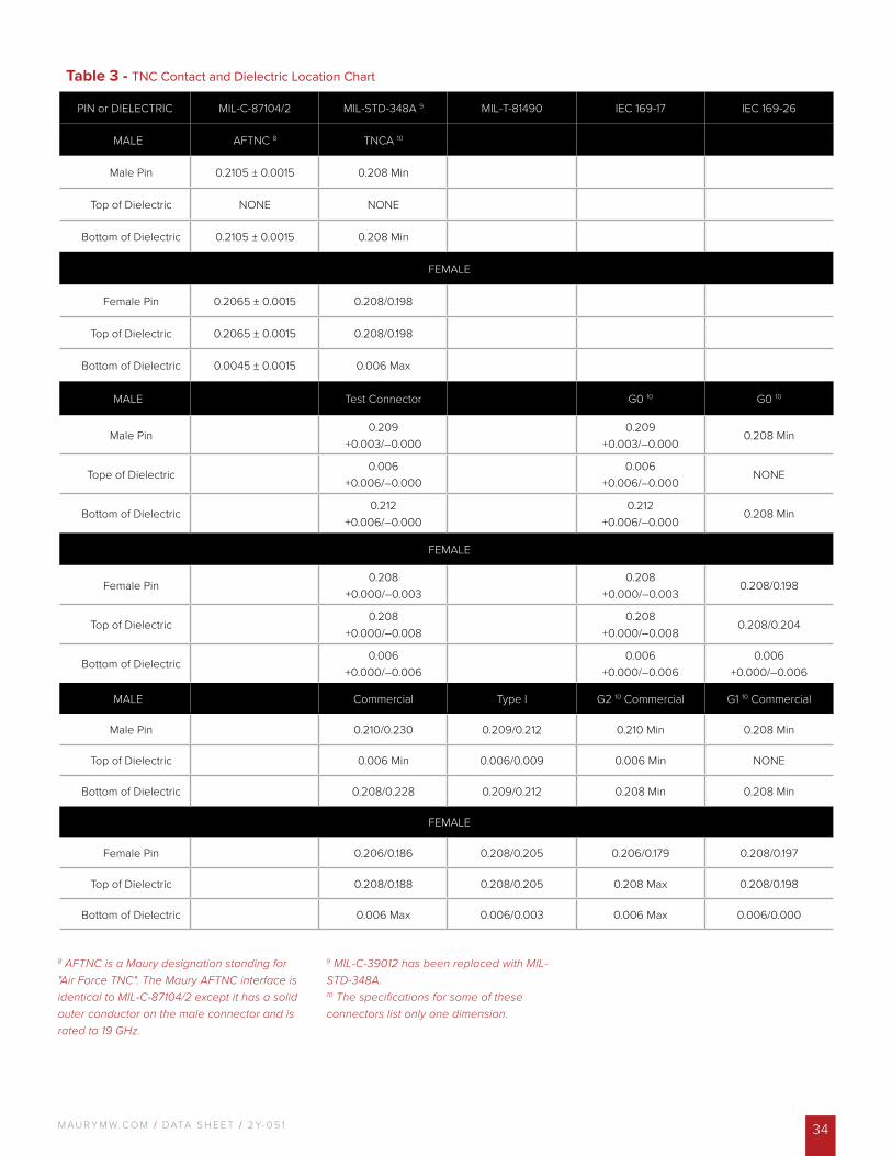
The Maury model A012A connector gage kit is designed to measure the contact pin and dielectric location of all commonly used TNC/BNC connectors. Generally the TNC and BNC are the same except the TNC is a screw on connector and the BNC is a bayonet type. To check the interface dimensions, requires three measurements for each connector to ensure the proper location of the contact pin and dielectric. These locations must be maintained within specifications for good electrical performance and to avoid connector damage when mated. Figure 1 shows the interface dimensions measured with this A012A connector gage kit. Table 1 gives the interface dimensions for earlier TNC/BNC designs. The interface dimensions of the more recent TNC connectors are shown in Table 3.
This gage kit provides a fast and accurate means for checking connectors for compliance to applicable interface specifications. Since it is basically a comparator, it can be used to check a variety of nominal dimensions. The indicator is zeroed by means of a master gage with the appropriate nominal dimension; then, it is engaged to the connector being tested. The resultant reading is the actual deviation from the nominal dimension. The accuracy of the measurement is the tolerance of the master gage nominal dimension itself.
The model A012A consists of a precision dial indicator assembly, interchangeable female and male measurement bushings and a master gage supplied in a wood instrument case with complete operating instructions. All gage parts and the master gage are made from stainless steel for long wearing characteristics.
The model A012A is very useful in a variety of applications such as: production checkout, incoming inspection, quality control and in the laboratory.
Features
> Direct Reading
> Self-Checking
> Accurate
> Easy To Use
Precision Grade TNC/BNC Push-on Connector Gage KitA012A SERIES
M AU R Y M W. C O M / DATA S H E E T / 2 Y- 0 5 133
Figure 1
Always check the manufacturer's specifications for the connector you are testing. The dimensions vary based on MIL-STD and IEC specifications used.
Dimensions (Inches)
1 Applies to TNC only. 2 Refer to Maury Data Sheet 5E-053.3 Per ASME B89.1.10M-2001, C5.1.2. 4 Per ASME B89.1.10M-2001, Table 2.5 Per manufacturers specifications.
6 Performance standards are in compliance with ANSI/NCSL Z540-1, MIL-STD-45662A and ISO 10012-1.7 Applies over the operating range for connector gaging +0.003/–0.009" from master gage zero setting.
Table 2
Characteristics Limits (inches) Comments
Gage Resolution ±0.000100 1/5 Least dial graduation 3
Gage Calibration Accuracy 7 ± 0.000750 1 Least dial graduation 4 plus 0.000250 measurement guardband
Gage Repeatability ± 0.000100 1/5 Least dial graduation 4
Master Accuracy (Linear)
± 0.000300 0.00060 Range 5
Total Uncertainty 6, 7
Worst Case ± 0.001250 Add resolution, repeatability, gage and master accuracy limits.
RSS ± 0.000820 Root sum of the squares.
Table 1 - BNC and TNC Interface Dimensions
SpecificationFemale Connector Male Connector
F1 F2 F3 M1 M2 M3
MIL-C-39012 (Class 2)
0.206 max 0.208 max 0.006 max 0.210 min 0.208 min 0.006 min
MIL-C-39012 (Standard
Test)
0.206+0.000/ –0.003
0.208+0.000/ –0.008
0.000+0.008/ –0.000
0.209+0.003/ –0.000
0.212+0.006/ –0.000
0.008+0.004/ –0.000
MIL-T-81490 (Type 1)1
0.208+0.000/ –0.003
0.208+0.000/ –0.003
0.003+0.003/ –0.000
0.209+0.003/ –0.000
0.209+0.003/ –0.000
0.006+0.003/ –0.000
MPC/TNC (ES-2047)1, 2
0.208+0.000/ –0.005
0.208+0.000/ –0.008
0.000+0.000/ –0.004
0.209+0.005/ –0.000
0.209+0.008/ –0.000
0.000+0.004/ –0.000
M AU R Y M W. C O M / DATA S H E E T / 2 Y- 0 5 1 34
Table 3 - TNC Contact and Dielectric Location Chart
PIN or DIELECTRIC MIL-C-87104/2 MIL-STD-348A 9 MIL-T-81490 IEC 169-17 IEC 169-26
MALE AFTNC 8 TNCA 10
Male Pin 0.2105 ± 0.0015 0.208 Min
Top of Dielectric NONE NONE
Bottom of Dielectric 0.2105 ± 0.0015 0.208 Min
FEMALE
Female Pin 0.2065 ± 0.0015 0.208/0.198
Top of Dielectric 0.2065 ± 0.0015 0.208/0.198
Bottom of Dielectric 0.0045 ± 0.0015 0.006 Max
MALE Test Connector G0 10 G0 10
Male Pin0.209
+0.003/–0.0000.209
+0.003/–0.0000.208 Min
Tope of Dielectric0.006
+0.006/–0.0000.006
+0.006/–0.000NONE
Bottom of Dielectric0.212
+0.006/–0.0000.212
+0.006/–0.0000.208 Min
FEMALE
Female Pin0.208
+0.000/–0.0030.208
+0.000/–0.0030.208/0.198
Top of Dielectric0.208
+0.000/–0.0080.208
+0.000/–0.0080.208/0.204
Bottom of Dielectric0.006
+0.000/–0.0060.006
+0.000/–0.0060.006
+0.000/–0.006
MALE Commercial Type I G2 10 Commercial G1 10 Commercial
Male Pin 0.210/0.230 0.209/0.212 0.210 Min 0.208 Min
Top of Dielectric 0.006 Min 0.006/0.009 0.006 Min NONE
Bottom of Dielectric 0.208/0.228 0.209/0.212 0.208 Min 0.208 Min
FEMALE
Female Pin 0.206/0.186 0.208/0.205 0.206/0.179 0.208/0.197
Top of Dielectric 0.208/0.188 0.208/0.205 0.208 Max 0.208/0.198
Bottom of Dielectric 0.006 Max 0.006/0.003 0.006 Max 0.006/0.000
8 AFTNC is a Maury designation standing for "Air Force TNC". The Maury AFTNC interface is identical to MIL-C-87104/2 except it has a solid outer conductor on the male connector and is rated to 19 GHz.
9 MIL-C-39012 has been replaced with MIL-STD-348A.10 The specifications for some of these connectors list only one dimension.
M AU R Y M W. C O M / DATA S H E E T / 2 Y- 0 5 135
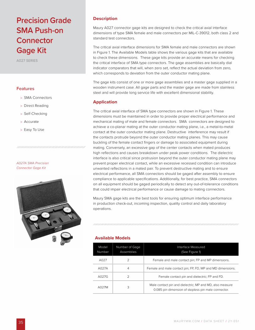
Description
Maury A027 connector gage kits are designed to check the critical axial interface dimensions of type SMA female and male connectors per MIL-C-39012, both class 2 and standard test connectors.
The critical axial interface dimensions for SMA female and male connectors are shown in Figure 1. The Available Models table shows the various gage kits that are available to check these dimensions. These gage kits provide an accurate means for checking the critical interface of SMA type connectors. The gage assemblies are basically dial indicator comparators that will, when zero set, reflect the actual deviation from zero, which corresponds to deviation from the outer conductor mating plane.
The gage kits consist of one or more gage assemblies and a master gage supplied in a wooden instrument case. All gage parts and the master gage are made from stainless steel and will provide long service life with excellent dimensional stability.
Application
The critical axial interface of SMA type connectors are shown in Figure 1. These dimensions must be maintained in order to provide proper electrical performance and mechanical mating of male and female connectors. SMA connectors are designed to achieve a co-planar mating at the outer conductor mating plane, i.e., a metal-to-metal contact at the outer conductor mating plane. Destructive interference may result if the contacts protrude beyond the outer conductor mating planes. This may cause buckling of the female contact fingers or damage to associated equipment during mating. Conversely, an excessive gap of the center contacts when mated produces high reflections and causes breakdown under peak power conditions. The dielectric interface is also critical since protrusion beyond the outer conductor mating plane may prevent proper electrical contact, while an excessive recessed condition can introduce unwanted reflections in a mated pair. To prevent destructive mating and to ensure electrical performance, all SMA connectors should be gaged after assembly to ensure compliance to applicable specifications. Additionally, for best practice, SMA connectors on all equipment should be gaged periodically to detect any out-of-tolerance conditions that could impair electrical performance or cause damage to mating connectors.
Maury SMA gage kits are the best tools for ensuring optimum interface performance in production check-out, incoming inspection, quality control and daily laboratory operations.
Precision Grade SMA Push-on Connector Gage KitA027 SERIES
A027A SMA Precision Connector Gage Kit
Features
> SMA Connectors
> Direct Reading
> Self-Checking
> Accurate
> Easy To Use
Available Models
Model Number
Number of Gage Assemblies
Interface Measured(See Figure 1)
A027 2 Female and male contact pin; FP and MP dimensions.
A027A 4 Female and male contact pin; FP, FD, MP and MD dimensions.
A027G 2 Female contact pin and dielectric; FP and FD.
A027M 3Male contact pin and dielectric; MP and MD, also measure
0.085 pin dimension of stepless pin male connector.
M AU R Y M W. C O M / DATA S H E E T / 2 Y- 0 5 1 36
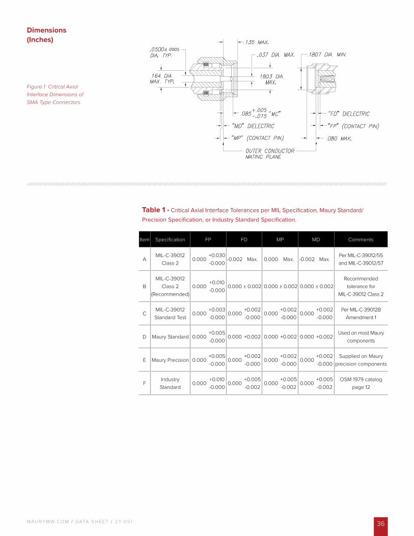
Figure 1 Critical Axial Interface Dimensions of SMA Type Connectors
Table 1 - Critical Axial Interface Tolerances per MIL Specification, Maury Standard/Precision Specification, or Industry Standard Specification.
Item Specification FP FD MP MD Comments
AMIL-C-39012
Class 20.000
+0.030-0.000
-0.002 Max. 0.000 Max. -0.002 Max.Per MIL-C-39012/55 and MIL-C-39012/57
BMIL-C-39012
Class 2 (Recommended)
0.000+0.010-0.000
0.000 ± 0.002 0.000 ± 0.002 0.000 ± 0.002Recommended
tolerance for MIL-C-39012 Class 2
CMIL-C-39012 Standard Test
0.000+0.003-0.000
0.000+0.002-0.000
0.000+0.002-0.000
0.000+0.002-0.000
Per MIL-C-39012B Amendment 1
D Maury Standard 0.000+0.005-0.000
0.000 +0.002 0.000 +0.002 0.000 +0.002Used on most Maury
components
E Maury Precision 0.000+0.005-0.000
0.000+0.002-0.000
0.000+0.002-0.000
0.000+0.002-0.000
Supplied on Maury precision components
FIndustry Standard
0.000+0.010-0.000
0.000+0.005-0.002
0.000+0.005-0.002
0.000+0.005-0.002
OSM 1979 catalog page 12
Dimensions (Inches)
M AU R Y M W. C O M / DATA S H E E T / 2 Y- 0 5 137
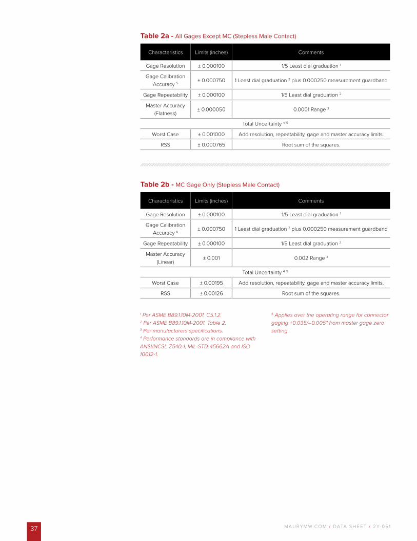
Table 2a - All Gages Except MC (Stepless Male Contact)
Characteristics Limits (inches) Comments
Gage Resolution ± 0.000100 1/5 Least dial graduation 1
Gage Calibration Accuracy 5 ± 0.000750 1 Least dial graduation 2 plus 0.000250 measurement guardband
Gage Repeatability ± 0.000100 1/5 Least dial graduation 2
Master Accuracy (Flatness)
± 0.000050 0.0001 Range 3
Total Uncertainty 4, 5
Worst Case ± 0.001000 Add resolution, repeatability, gage and master accuracy limits.
RSS ± 0.000765 Root sum of the squares.
Table 2b - MC Gage Only (Stepless Male Contact)
Characteristics Limits (inches) Comments
Gage Resolution ± 0.000100 1/5 Least dial graduation 1
Gage Calibration Accuracy 5 ± 0.000750 1 Least dial graduation 2 plus 0.000250 measurement guardband
Gage Repeatability ± 0.000100 1/5 Least dial graduation 2
Master Accuracy (Linear)
± 0.001 0.002 Range 3
Total Uncertainty 4, 5
Worst Case ± 0.00195 Add resolution, repeatability, gage and master accuracy limits.
RSS ± 0.00126 Root sum of the squares.
1 Per ASME B89.1.10M-2001, C5.1.2. 2 Per ASME B89.1.10M-2001, Table 2.3 Per manufacturers specifications.4 Performance standards are in compliance with ANSI/NCSL Z540-1, MIL-STD-45662A and ISO 10012-1.
5 Applies over the operating range for connector gaging +0.035/–0.005" from master gage zero setting.
M AU R Y M W. C O M / DATA S H E E T / 2 Y- 0 5 1 38
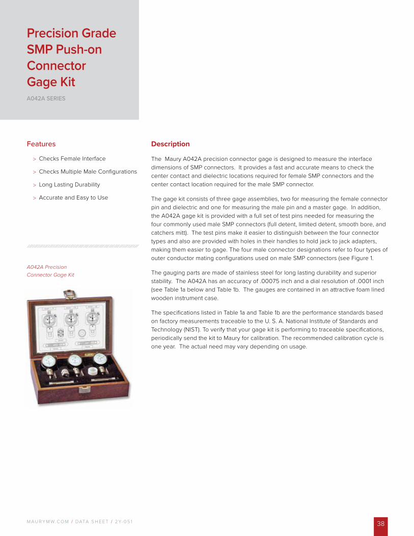
A042A Precision Connector Gage Kit
Description
The Maury A042A precision connector gage is designed to measure the interface dimensions of SMP connectors. It provides a fast and accurate means to check the center contact and dielectric locations required for female SMP connectors and the center contact location required for the male SMP connector.
The gage kit consists of three gage assemblies, two for measuring the female connector pin and dielectric and one for measuring the male pin and a master gage. In addition, the A042A gage kit is provided with a full set of test pins needed for measuring the four commonly used male SMP connectors (full detent, limited detent, smooth bore, and catchers mitt). The test pins make it easier to distinguish between the four connector types and also are provided with holes in their handles to hold jack to jack adapters, making them easier to gage. The four male connector designations refer to four types of outer conductor mating configurations used on male SMP connectors (see Figure 1.
The gauging parts are made of stainless steel for long lasting durability and superior stability. The A042A has an accuracy of .00075 inch and a dial resolution of .0001 inch (see Table 1a below and Table 1b. The gauges are contained in an attractive foam lined wooden instrument case.
The specifications listed in Table 1a and Table 1b are the performance standards based on factory measurements traceable to the U. S. A. National Institute of Standards and Technology (NIST). To verify that your gage kit is performing to traceable specifications, periodically send the kit to Maury for calibration. The recommended calibration cycle is one year. The actual need may vary depending on usage.
Features
> Checks Female Interface
> Checks Multiple Male Configurations
> Long Lasting Durability
> Accurate and Easy to Use
Precision Grade SMP Push-on Connector Gage KitA042A SERIES
M AU R Y M W. C O M / DATA S H E E T / 2 Y- 0 5 139
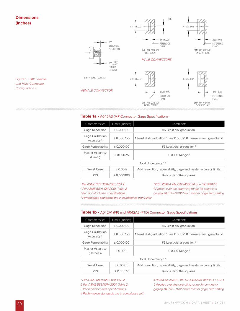
Dimensions (Inches)
1 Per ASME B89.1.10M-2001, C5.1.2. 2 Per ASME B89.1.10M-2001, Table 2.3 Per manufacturers specifications.4 Performance standards are in compliance with ANSI/
NCSL Z540-1, MIL-STD-45662A and ISO 10012-1.5 Applies over the operating range for connector gaging +0.015/–0.005" from master gage zero setting.
1 Per ASME B89.1.10M-2001, C5.1.2. 2 Per ASME B89.1.10M-2001, Table 2.3 Per manufacturers specifications.4 Performance standards are in compliance with
ANSI/NCSL Z540-1, MIL-STD-45662A and ISO 10012-1.5 Applies over the operating range for connector gaging +0.015/–0.005" from master gage zero setting.
Table 1a - A042A3 (MP)Connector Gage Specifications
Characteristics Limits (inches) Comments
Gage Resolution ± 0.000100 1/5 Least dial graduation 1
Gage Calibration Accuracy 5 ± 0.000750 1 Least dial graduation 2 plus 0.000250 measurement guardband
Gage Repeatability ± 0.000100 1/5 Least dial graduation 2
Master Accuracy (Linear)
± 0.00025 0.0005 Range 3
Total Uncertainty 4, 5
Worst Case ± 0.0012 Add resolution, repeatability, gage and master accuracy limits.
RSS ± 0.000803 Root sum of the squares.
Table 1b - A042A1 (FP) and A042A2 (FTD) Connector Gage Specifications
Characteristics Limits (inches) Comments
Gage Resolution ± 0.000100 1/5 Least dial graduation 1
Gage Calibration Accuracy 5 ± 0.000750 1 Least dial graduation 2 plus 0.000250 measurement guardband
Gage Repeatability ± 0.000100 1/5 Least dial graduation 2
Master Accuracy (Flatness)
± 0.0001 0.0002 Range 3
Total Uncertainty 4, 5
Worst Case ± 0.00105 Add resolution, repeatability, gage and master accuracy limits.
RSS ± 0.00077 Root sum of the squares.
Figure 1. SMP Female and Male Connector Configurations
FEMALE CONNECTOR
MALE CONNECTORS
M AU R Y M W. C O M / DATA S H E E T / 2 Y- 0 5 1 40
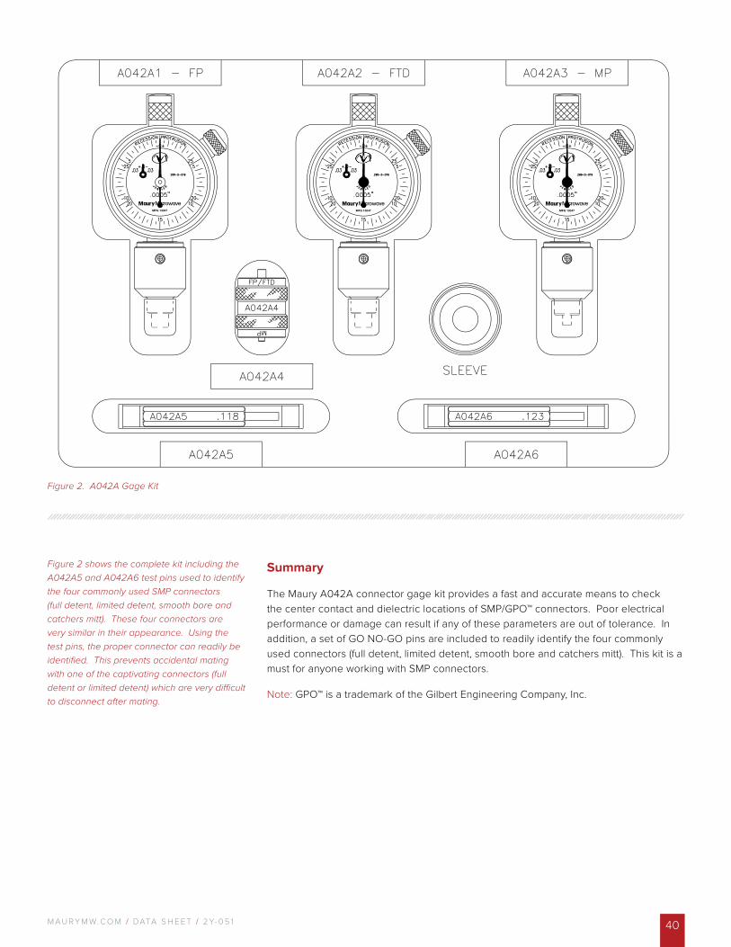
Figure 2 shows the complete kit including the A042A5 and A042A6 test pins used to identify the four commonly used SMP connectors (full detent, limited detent, smooth bore and catchers mitt). These four connectors are very similar in their appearance. Using the test pins, the proper connector can readily be identified. This prevents accidental mating with one of the captivating connectors (full detent or limited detent) which are very difficult to disconnect after mating.
Summary
The Maury A042A connector gage kit provides a fast and accurate means to check the center contact and dielectric locations of SMP/GPO™ connectors. Poor electrical performance or damage can result if any of these parameters are out of tolerance. In addition, a set of GO NO-GO pins are included to readily identify the four commonly used connectors (full detent, limited detent, smooth bore and catchers mitt). This kit is a must for anyone working with SMP connectors.
Note: GPO™ is a trademark of the Gilbert Engineering Company, Inc.
Figure 2. A042A Gage Kit

V I S I T O U R W E B S T O R E
T O L E A R N M O R E A B O U T
O U R P R O D U C T S
w w w . m a u r y m w . c o m____
C O N TAC T U S :W / maurymw.comE / [email protected] / +1-909-987-4715 F / +1-909-987-11122900 Inland Empire BlvdOntario, CA 91764
DATA S H E E T / 2 Y- 0 5 1 © 2019 Maury Microwave Corporation. All Rights Reserved.Specifications are subject to change without notice.Maury Microwave is AS9100D & ISO 9001:2015 Certified.