CONNECTIVITY CATALOGUE - ACE fibre optic networks · CONNECTIVITY CATALOGUE INNOVATIVE FIBRE OPTIC...
58
TELECOM SOLUTIONS CONNECTIVITY CATALOGUE INNOVATIVE FIBRE OPTIC CABLE SOLUTIONS SOLUTIONS
Transcript of CONNECTIVITY CATALOGUE - ACE fibre optic networks · CONNECTIVITY CATALOGUE INNOVATIVE FIBRE OPTIC...

TELECOM SOLUTIONS
CONNECTIVITY CATALOGUE INNOVATIVE FIBRE OPTIC CABLE SOLUTIONS
SOLUTIONS

33
Since its establishment in 1930 TKF developed from a cable producer to a leading supplier of connectivity solutions located in the Netherlands. A broad range of cables, systems and services enables us to provide our customers worldwide with safe and reliable power and data connections.
Due to a focused commitment, TKF is distinguished by specialized application knowledge and solutions with a high degree of reliability, quality and service. Specialized technical know-how and flexibility lead to a high return on investment for our customers.
TKF is characterized by continuous investment in customer relations, quality and supplementary services, resulting in sustainable cable solutions and long-term and successful relationships.
It goes without saying that we offer our customized solutions with respect for people and environment. Being part of the technology company TKH Group NV, TKF has access to breakthrough solutions, concepts and technologies.
TKF TECHNOLOGICAL LEADERSHIP IN CONNECTIVITY SOLUTIONS
More than 85 years of experience
Building Solutions » Building » Energy » Infrastructure » Renewable » Rail infra
Industrial Solutions » Industry » Marine & offshore » Oil, gas &
petrochemical
Telecom Solutions » Telecom
Our core values
» Innovativeness » Maximum reliability » Outstanding quality » High service degree » Corporate Social
Responsibility
Our market segmentation

44 Copyright © TKF • No rights can be derived from this information.
TKH Group NV (TKH) is an internationally operating group of companies specialized in creating and supplying innovative Telecom, Building and Industrial Solutions.
All TKH technologies are interlinked into total solutions for these three business segments. Specialists in the fields of marketing, process development, design, engineering and logistics add advice and project implementation to offer a tailor-made solution. TKH aims to carve out strong market positions based mainly on its own advanced technologies and services and on its strong regional and international positioning.
The group’s growth is concentrated in North-Western, Central and Eastern Europe and in Asia. TKH is known for its innovations and its commitment to renewal. The urge to lead is great. TKH places its experience and knowledge into the service of its clients, and jointly looks for optimal solutions.
The four TKH core technologies:Vision & Security | Communications | Connectivity | Manufacturing Systems
MEET THE TKH GROUP ANDITS CORE TECHNOLOGIES
www.tkhgroup.com

55
TOTAL SOLUTIONS FOR MODERNFIBRE OPTIC NETWORKS 6
1 POPRack System ODF-PMF-PPF 10HD Fastconnect Splice/Patch Shelf 11Optical Distribution Frame Light 12Compact ODF 14Pivoting Tray Drawer 15Sliding Tray Drawer 17Sliding Splicing Drawer 19Patch-cord Management Shelf 20
2 OSP Ducts and Tubes 21 Multi Tube Cables 22 Connectors 23 Divisible connectors 24 Tube Management Closures 25 Small Termination Closure 26 μODCClosure 27 µODC Sealing kits 28 μODCConfigurations 28 Compact Fibre Optical Closure 29 Fibre Optical Closure 30 Demarcation Optical Closure 32 Heatshrink Sealing Kits 33 Mechanical Sealing Kits 34 Closure Accessories 35 Street Cabinets 36
3 SubscriberNext Generation Box 37NGB2 Light Splice 38NGB2 Demarcation Point 38NGB1 Splice 39NGB1 Splice/patch 39
NGB Splice 39Sealing kits 40ACE FTU 41FTU patch cover 41ACE Customer Outlet 42ACE DIN Wall Outlet 43ACE DIN Rail Module 44ACE Splice Tray High Density 45PLC Splitters single mode 46Small Case Splitters 46Hard Case Splitters 47Pigtails 48Patch-cords 48Adapters 48Cable Assemblies 49House Entry Kit 50Heat shrink Splice Protector 51Crimp Splice Protector (ANT) 51Cleaner pen 52
TELECOM SOLUTIONS 53
MORE INFORMATION 54
CONTENTS

6
The demand for broadband solutions is constantly rising. That means that the number of fibre optic networks is also increasing worldwide. The size and topology of these networks vary by region. Therefore, TKF is constantly innovating in the field of Telecom Solutions. For improved, flexible, cost-saving and easy to install solutions.
Our ACE conceptAs a total solutions supplier within the TKH Group NV, TKF developed the ACE concept, a total solution for modern fibre optic networks. ACE is a certified and guaranteed concept for passive FTTx networks. As a total concept ACE provides the broadband market with a new vision on building fibre optic networks. ACE does not only consist of products, but also guarantees compatibility between all the different components and offers complete, passive solutions.
TOTAL SOLUTIONS FOR MODERN FIBRE OPTIC NETWORKS
6

7
The ACE concept is mainly a success of people. People with knowledge and skills concentrated in the ACE team. Together with our customers we share technical knowledge and help our customers to stay ahead with our continuous developments. ACE not only has the right products, but also ensures that the various components fit together seamlessly in the fields of application: POP, OSP and Subscriber.
7

8
POP SolutionsBuilding a FTTx network starts at the drawing
board where configuration, technology and planning are defined. One of the most challenging parts of the network is the POP (point of presence). This is the centre (heart) of the network where all connections are made and active equipment is installed and operated. It is essential to exclude all possible risks during installation and operation. TKF has gathered all its experience and know-how within the ACE concept, to cover the full range of options to achieve an optimal POP performance. POP’s need to be built close to the subscribers. Moreover they need to fit into this environment and meet the requirements of the subscribers on construction, size, shape, colour, noise and place. TKF has set up a flexible design that meets all demands. A street cabinet solution or a large POP building, they all fit within the ACE concept.
The ACE POP solution offers:• Flexible design• High and super high density ODF• Optional SAODF (semi-automated ODF)• Third operator solution• Partial delivery or turnkey solution
OSP SolutionsCivil work is the major cost driver (>70%)
of the total cost ofownership (TCO), to build FTTx networks. The cost of civil work vary from country to country, sandy or rocky soil and paving: tiles, concrete or no paving at all, make a big difference in cost. Within the ACE concept TKF offers solutions for each OSP network to lower the cost per individual challenge.
Direct burial cable solution:Within the ACE concept, TKF has developed a full range of products making the installation of a direct burial cable concept easy and cost saving. Heavy duty steel or Kevlar protected cables are available together with all components, like closures and access chambers that fit in this application.
Modular cabling solution:In order to meet the various demands (success based installations) it is often required to use a modular cabling system in FTTx networks. ACE offers a full modular cable solution including all accessories like closures, duct connectors, fibre blowing equipment and a special ODF, for easy installation of all tubes within the POP or street cabinet.
21
1

9
Aerial solution:In case of existing aerial infrastructure (f.i. power lines), it can be cost saving to use this infrastructure to install a FTTx network. ACE offers a full range of ADSS cables suitable for this application. TKF has experience with sewer paths and fibre through gas pipelines. To prevent expensive digging operations, TKF has looked at all the different trenching possibilities, like macro and nano trenching. All these cost saving solutions can be fully integrated within the ACE concept with warranty and certification.
Subscriber SolutionsThe main challenge when building a FTTx
network is getting access to the subscriber. As we are operating within the public sector, possible challenges are:• Availability of subscribers during office hours• Wishes and demands of house and building
owners• Local regulations and cooperation of all
subscribers in the chain: - Are we allowed to install on the outside of the
building? - Can we install in hallways, cellars or elevator shafts?
All these solutions and installation options require tailor made products and systems. TKF has developed a total ACE subscriber solution for both single and multi dwelling units (SDU and MDU), that fit all these demands and still keep the cost low. Special indoor and outdoor cables have been developed. And a full series of fibre splice and patch boxes are available in all required sizes and shapes, designed and tested for this challenging environment.
3
2
3

10
POP
OSP
Subscriber
10
Rack System ODF-PMF-PPFRacks
The ACE rack system is designed for housingpassivecomponentsforfibredistribution.Theracksystemoffersspacefor optical distribution shelves, patch panel shelves, splitters and other 19” components.
Every height unit can be reached via the keen ACE patch-cord management system, which makes it possible to connect every position inside the rack system with only one cable length. The cablecamsprovideeasyfixationandmanagement of cables. The separation plates on the bend controllers separates the ring feeder patch-cords from the ODF patch cords.
The rack system is provided with cable protection brackets for feeder and distribution cables.
Features and applications• FTTH POP housing• High density FTTH networks• Suitable for 19” splice/patch shelfs, patch panel shelfs,
splitters and other 19” components• ACE patch-cord management system• Bend radius protection throughout the frame• Fully front accessibility• Compact and light weight design•Maximumflexibilityandmodularity• Cable entry top and bottom
Parameter Unit ACE-Rack system
Dimension
Height
mm
2200
Width 1800
Depth 400
Capacity 2 x 47 HU
HD fastconnect capacity 4512 LC / 2256 SC
Colour Powder coated RAL7035
Art. number ACE code Description
561676 RS-WT-A2-NN0-01 ODF Left + PMF + PPF 2200 x 1800 x 400 mm (hxwxd)
561677 RS-WT-A1-NN0-01 ODF Right + PMF + PPF 2200 x 1800 x 400 mm (hxwxd)
N.B.: For customized design or complete solutions, please contact your TKF sales representative.

POP
OSP
Subscriber
11
HD Fastconnect Splice/Patch ShelfShelves
The HD fastconnect splice/patch shelf is a versatile 1 HU shelf. The shelf is used forsplicingandpatchingfibersofanoptical cable in a rack environment. The shelf accommodates up to 4 ACE HD Fastconnect trays for a total capacity of 96 LC positions. Tubes of the feeder cable entertheshelfattheback.Thefibresare terminated to pigtails (SC or LC) and connected onto the adapters. Stripped pigtails (individual strip lengths) and adapters are mounted in the shelf. Four front patch trays are mounted inside a slide rail. Orientation of adapters is to the right or left side. Patch-cords are guided to the patch-cord management frame at the same side of the tray. For easy accessibility during patching, access to the individual trays is achieved by a two-step sliding mechanism. Unambiguous coding on the trays reduces the risk of mistakes during patching to a minimum.
Features and applications• Compact and light weight design•1HU-19”-96fibers• Stripped pigtails and premounted adapters reduce
installation time• Two-step sliding mechanism for easy accessibility• High density FTTH networks• Suitable for mounting in the ACE rack system• Extension kit transforms two 1HU shelves to one 2HU shelf• Feeder cable protection
Parameter Unit Splice/Patch shelf type L
Dimension
Height
mm
44.4
Width 510
Depth 200 (excl. bend control guide)
Capacity1 HU4 HD Fastconnect trays96 LC or 48 SC positions
Colour
Frame: blackOverlength storage module: greenPatch tray: Natural whitePigtails: IEC 60304 / VDE 0888-3
Art. number ACE code Description
485008 SH-L1-BLS-VL7 HD Fastconnect Splice/patch shelf - 19” right prefab 96x LC/APC 8°
485009 SH-L1-ALS-VL7 HD Fastconnect Splice/patch shelf - 19” left prefab 96x LC/APC 8°
485002 SH-L1-BLS-VL5 HD Fastconnect Splice/patch shelf - 19” right prefab 96x LC/PC
485003 SH-L1-ALS-VL5 HD Fastconnect Splice/patch shelf - 19” left prefab 96x LC/PC
485004 SH-L1-BMS-NS7 HD Fastconnect Splice/patch shelf - 19” right prefab 48x SC/APC 8°
485005 SH-L1-AMS-NS7 HD Fastconnect Splice/patch shelf - 19” left prefab 48x SC/APC 8°
485020 SH-L1-EXT-01 Extension kit shelf type L connecting 2 shelves 1HU incl. protection cover
N.B.: Above part numbers refer to crimp splice protector holders. For other configurations please contact your TKF sales representative.

12
POP
OSP
Subscriber
12
Optical Distribution Frame LightRacks
The ACE-ODFL is an ETSI all-purpose metal rack designed to reach the maximummodularityandflexibilitywhichalso allows easy on-site assembly.
Thedesignsuitsanyspecificapplicationchangingtherackconfigurationcomposed of modular units, a central frame and side extensions. These can easily be combined to create differentlayouts.
Optical cables and patch-cords are organized, stored and mechanically protected in the side extensions of the rack.Thefiberscanentertheshelvesfrom the left, right or the backside with the controlled bending on all cords.
Within the rack and side modules there is completeflexibilityinpatchingfromoneside to the other. The bend controllers in the side modules allow the use of a single patch-cord length with excess cord length storage in a proper manner.
Parameter Unit ACE-ODFL-1 ACE-ODFL-2
Dimension
Height
mm
2000 2200
Width See ordering info
Depth 300
Capacity 72 MU 80 MU
Colour Powder coated RAL7035
Mounting frames ETSI, back mounting
ACE-ODFL-x-600-A ACE-ODFL-x-900-A ACE-ODFL-x-1050-A ACE-ODFL-x-1200-A
POP
OSP
Subscriber
13
Art. number ACE code Description
400876 ACE-ODFL-1-600-A ETSI Rack 2000 x 600 x 300 mm (hxwxd)
400875 ACE-ODFL-1-900-A ETSI Rack 2000 x 900 x 300 mm (hxwxd)
400877 ACE-ODFL-1-1050-A ETSI Rack 2000 x 1050 x 300 mm (hxwxd)
400874 ACE-ODFL-1-1200-A ETSI Rack 2000 x 1200 x 300 mm (hxwxd)
400871 ACE-ODFL-2-600-A ETSI Rack 2200 x 600 x 300 mm (hxwxd)
400870 ACE-ODFL-2-900-A ETSI Rack 2200 x 900 x 300 mm (hxwxd)
400868 ACE-ODFL-2-1050-A ETSI Rack 2200 x 1050 x 300 mm (hxwxd)
400869 ACE-ODFL-2-1200-A ETSI Rack 2200 x 1200 x 300 mm (hxwxd)
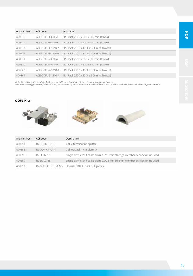
Art. number ACE code Description
400853 RS-STD KIT-CTS Cable termination splitter
400856 RS-ODF-KIT-CPK Cable attachment plate kit
400858 RS-SC-12/16 Single clamp for 1 cable diam. 12/16 mm Strengh member connector included
400859 RS-SC-22/28 Single clamp for 1 cable diam. 22/28 mm Strengh member connector included
400857 RS-ODFL-KIT-6 DRUMS Drum kit ODFL, pack of 6 pieces
N.B.: For each side module 150 mm or 300 mm there are 6 patch-cord drums included.For other configurations, side to side, back to back, with or without central doors etc. please contact your TKF sales representative.
ODFL Kits

14
POP
OSP
Subscriber
14
ACE Compact Optical Distribution Frame isdevelopedtomanagealltypesoffibrecable in restricted space.
Each door and panel can be removed and locked by a handle. Cable entrance and patch-cord outlet are possible at the top and at the bottom of the rack.
A sub-rack can be drawn out easily with free access to splicing and patching areas. Modular concept allows basic rack to accommodate up to 5 modules for patching/splicing.
ACE Compact ODF capacity can vary from 120fibers(twofiberspertray)upto240fibers(fourfiberspertray)withsingle-circuitsfibremanagement.
Compact ODFRacks
Features and applications• ETSI standard• Unbundling access networks•Smallareacentraloffice• Compact multipurpose patch/splice rack
and modules• Modular concept, all panels removable• Patch-cord management and extra-
length storage
Art. number ACE code Description
400880 RS-CODF-2-300-AN Compact ODF 2200x300x300 mm (hxwxd)
400881 RS-CODF-SR-1 48 SC/PC simplex preloaded subrack
400882 RS-CODF-SR-2 24 LC/PC duplex preloaded subrack
400883 RS-CODF-SR-3 48 SC/APC simplex preloaded subrack
400884 RS-CODF-SR-4 24 LC/APC duplex preloaded subrack
Description
Dimensions (mm) 2200x300x300 (hxwxd)
Colour RAL-7035 (powder coated)
Rack capability up to 5 modules
Sub-rack capability 24 LC duplex or 48 SC simplex connectors
Pigtail colour White
N.B.: Above part numbers refer to heat shrink splice protector holders. For other configurations please contact your TKF sales representative.

POP
OSP
Subscriber
15
TheACEPivotingTrayDrawerissuitabletospliceandpatchfibreopticcablesusingthemostcommonconnector types (SC footprint). It can easily integrate splitters, WDMs and any other passive components. Thedrawerisafixed19”frameinwhichpivotingtraysaremounted.Ineachtraysplicecassettes,pigtailsand connectors can be pre-assembled.
Theunitcanhavethefollowingconfigurations:• patch and splice• patch and patch
19” or ETSI mounting brackets for back mounting are provided. Removable front cover and pivoting tray allow easy patch-cord installation and re-accessibility. Angled patch panel reduces the risk of eye damage. Minimum bending radius 30 mm is guaranteed. The drawer is painted in light grey (powder coated) RAL 7035.
Pivoting Tray DrawerShelves
Features and applications• Ultimate connectivity density• Pivoting trays for easy installation and maintenance• Full bend radius control• Pre-loaded pigtails• Inside and outside plant installation• Future proof for high density applications

16
POP
OSP
Subscriber
16
Pivoting Tray DrawerShelves
19” - 1 unit
19” - 2 units
19” - 3 units
19”- 4 units
PTDDimension in mm Capacities
Height Width* Depth no. F.O.
19” - 1U 44 445 280 up to 48
19” - 2U 85 445 280 up to 96
19” - 3U 125 445 280 up to 144
19”- 4U 167 445 280 up to 192
* Dimension excl. mounting brackets
N.B.: Above part numbers refer to heat shrink splice protector holders, pigtail colour white.For other configurations please contact your TKF sales representative.
Art. number ACE code Description
405709 SH-PTD-MIR1-HD4-12H-S2-48-48 PTD - 1HU, 19”, right pivoting incl. 48x SC/APC 8° pigtails & adapters
405712 SH-PTD-MIR2-HD4-12H-S2-96-96 PTD - 2HU, 19”, right pivoting incl. 96x SC/APC 8° pigtails & adapters
405713 SH-PTD-MIR3-HD4-12H-S2-144-144 PTD - 3HU, 19”, right pivoting incl. 144x SC/APC 8° pigtails & adapters
405721 SH-PTD-MIR4-HD4-12H-S2-192-192 PTD - 4HU 19” right pivoting incl. 192x SC/APC 8° pigtails & adapters
405717 SH-PTD-MIL1-HD4-12H-S2-48-48 PTD - 1HU, 19”, left pivoting incl. 48x SC/APC 8° pigtails & adapters
405718 SH-PTD-MIL2-HD4-12H-S2-96-96 PTD - 2HU, 19”, left pivoting incl. 96x SC/APC 8° pigtails & adapters
405719 SH-PTD-MIL3-HD4-12H-S2-144-144 PTD - 3HU, 19”, left pivoting incl. 144x SC/APC 8° pigtails & adapt
405722 SH-PTD-MIL4-HD4-12H-S2-192-192 PTD - 4HU 19” left pivoting incl. 192x SC/APC 8° pigtails & adapters

POP
OSP
Subscriber
17
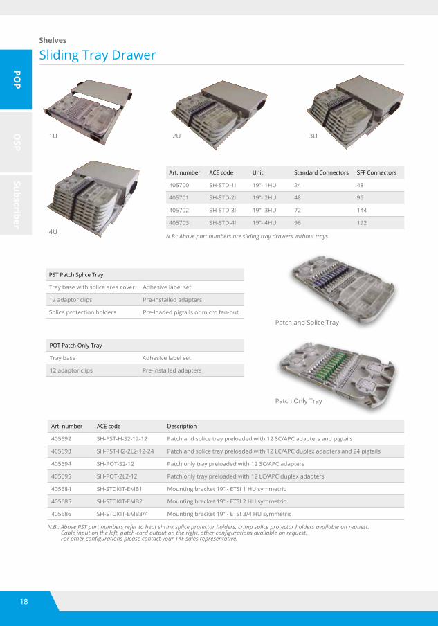
Sliding Tray DrawerShelves
* Dimension excl. mounting brackets
ACE sliding tray drawer is used for splicing loose tube cables to pigtails and patching, and patching the pigtails to patch-cords or for patching only (patch-cords and assemblies).
The ACE sliding tray drawer is used instead of front patching, when full easy access at both sides of the connection is required.
Whithin the tray a patch can be made to every position with a perfect control of the patchcord overlength.
Accurate design and compact adapters allow to accommodate 12 terminations (24 SFF connectors) per tray.
Swing-removable adapter holders make it easy to access the connection at both sides. Kits to attach cables at the side or at the back of the shelf are available.
PLC splitters or other optical passive components can be integrated.
Parameters Tray Unit 19”
Dimensions
Height
2
mm
44 (1HU 1.75”)
4 88 (2HU 3.5”)
6 125 (3HU 5.25”)
8 167 (4HU 7.0”)
Width 445*
Depth 280
Colour Powder coated RAL7035
Pigtail colour White
Pre-loaded drawerswith adaptersand pigtails areavailable
18
POP
OSP
Subscriber
18
1U 2U 3U
4U
Art. number ACE code Unit Standard Connectors SFF Connectors
405700 SH-STD-1I 19”- 1HU 24 48
405701 SH-STD-2I 19”- 2HU 48 96
405702 SH-STD-3I 19”- 3HU 72 144
405703 SH-STD-4I 19”- 4HU 96 192
N.B.: Above part numbers are sliding tray drawers without trays
Patch and Splice Tray
Patch Only Tray
PST Patch Splice Tray
Tray base with splice area cover Adhesive label set
12 adaptor clips Pre-installed adapters
Splice protection holders Pre-loaded pigtails or micro fan-out
POT Patch Only Tray
Tray base Adhesive label set
12 adaptor clips Pre-installed adapters
Art. number ACE code Description
405692 SH-PST-H-S2-12-12 Patch and splice tray preloaded with 12 SC/APC adapters and pigtails
405693 SH-PST-H2-2L2-12-24 Patch and splice tray preloaded with 12 LC/APC duplex adapters and 24 pigtails
405694 SH-POT-S2-12 Patch only tray preloaded with 12 SC/APC adapters
405695 SH-POT-2L2-12 Patch only tray preloaded with 12 LC/APC duplex adapters
405684 SH-STDKIT-EMB1 Mounting bracket 19” - ETSI 1 HU symmetric
405685 SH-STDKIT-EMB2 Mounting bracket 19” - ETSI 2 HU symmetric
405686 SH-STDKIT-EMB3/4 Mounting bracket 19” - ETSI 3/4 HU symmetric
N.B.: Above PST part numbers refer to heat shrink splice protector holders, crimp splice protector holders available on request. Cable input on the left, patch-cord output on the right, other configurations available on request. For other configurations please contact your TKF sales representative.
Sliding Tray DrawerShelves

POP
OSP
Subscriber
19
Sliding Splicing DrawerShelves
Subrack TypeDimension in mm
Unitheight depth width*
SSD 19" 125 280 445 3U
The ACE Sliding Splicing Drawer is a product designed to splice cables to cables and cable to pigtails. The product can be used inside the ODF racks in combination with STD shelves to terminate pigtails.
The main distinguishing features of the product are the use of HD splice trays for splicing, the integration of passive components such as PLCs, the ability to terminate pigtails using optical Pigtail Kevlar Retainer and to facilitate the installation withpre-assemblytubestoguidethefiberswithinthe sub-rack to reach the splice trays.
Please refer to ACE-STHD splice trays to configure your splice needs
* Dimension excl. mounting brackets
Splicing Capacity
Splicing Cable to Pigtails
SSD 19”
fibers trays
2fiberspertray 96 48
4fiberspertray 192 48
Splicing Capacity
Splicing Cable to Cable
SSD 19”
fibers trays
2fiberspertray 96 48
4fiberspertray 192 48
12fiberspertray 576 48
PKR Kit
Art. number ACE code Description
405730 SH-SSD-3I-C2P-N Sliding splicing drawer - 3 units, 19" - cable to pigtails - empty
405731 SH-SSD-3I-C2C-N Sliding splicing drawer - 3 units, 19" - cable to cable - empty
405740 SH-SDKIT-PKRM Splicing drawer kit - pigtail kevlar retainer
405686 SH-STDKIT-EMB3/4 Mounting bracket 19” - ETSI 3/4 HU symmetric
N.B.: For other configurations please contact your TKF sales representative. SDKIT-PKRM = 1x bend controller & 6x retainer.
20
POP
OSP
Subscriber
20
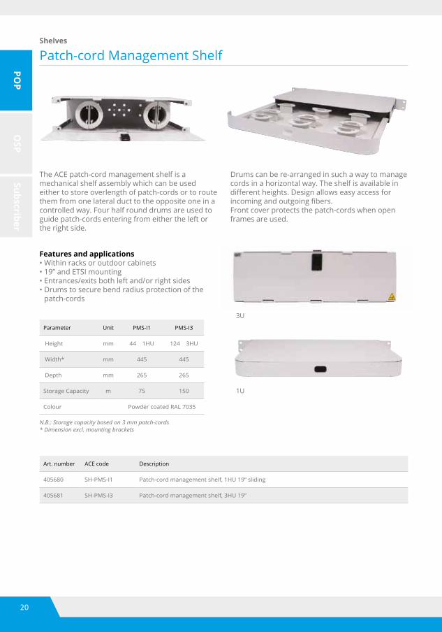
The ACE patch-cord management shelf is a mechanical shelf assembly which can be used either to store overlength of patch-cords or to route them from one lateral duct to the opposite one in a controlled way. Four half round drums are used to guide patch-cords entering from either the left or the right side.
Drums can be re-arranged in such a way to manage cords in a horizontal way. The shelf is available in differentheights.Designallowseasyaccessforincomingandoutgoingfibers.Front cover protects the patch-cords when open frames are used.
Patch-cord Management ShelfShelves
Features and applications• Within racks or outdoor cabinets• 19” and ETSI mounting• Entrances/exits both left and/or right sides• Drums to secure bend radius protection of the
patch-cords
3U
1U
Art. number ACE code Description
405680 SH-PMS-I1 Patch-cord management shelf, 1HU 19” sliding
405681 SH-PMS-I3 Patch-cord management shelf, 3HU 19”
Parameter Unit PMS-I1 PMS-I3
Height mm 44 1HU 124 3HU
Width* mm 445 445
Depth mm 265 265
Storage Capacity m 75 150
Colour Powder coated RAL 7035
N.B.: Storage capacity based on 3 mm patch-cords* Dimension excl. mounting brackets

21
POP
OSP
Subscriber
Ducts and TubesDucts and Tubes
Features and applications• Ducts and tubes are tested in combination with TKF cables• Ducts and tubes are an integrated part of the ACE solution• Large scale experience in civil works and cable blowing• ACE connectors designed and tested in combination with the
ducts and tubes
N.B.: For detailed information about ducts and tubes please contact your TKF sales representative.
Ductsandtubesofferaprotectivepathforfibreinfrastructure.3Classificationscanbedistinguished: microtubeswithadiameter≤Ø5mm,mostlybundledinmultitubecables,minitubeswithadiameter≤Ø16mm,thesearebundlesinmultitubecablesorutilizedassingleconduit,andductswithadiameter>Ø16mm.
HDPE duct Mini tube PE direct buried
Mini tube PE Mini tube indoor LFH Micro tube PE
Mini tube PE direct buried
TKF cable blowing test facility
22
POP
OSP
Subscriber
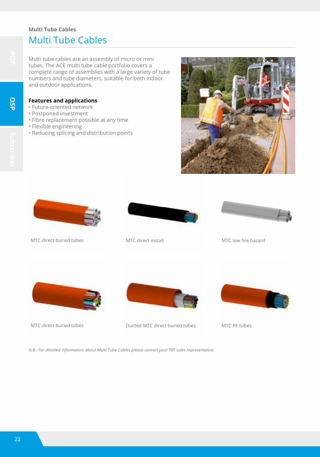
Multi Tube CablesMulti Tube Cables
Multi tube cables are an assembly of micro or mini tubes. The ACE multi tube cable portfolio covers a complete range of assemblies with a large variety of tube numbers and tube diameters, suitable for both indoor and outdoor applications.
Features and applications• Future-oriented network• Postponed investment• Fibre replacement possible at any time• Flexible engineering• Reducing splicing and distribution points
MTC direct buried tubes
MTC direct buried tubes
MTC direct install
Ducted MTC direct buried tubes
MTClowfirehazard
MTC PE tubes
N.B.: For detailed information about Multi Tube Cables please contact your TKF sales representative.

23
POP
OSP
Subscriber
ConnectorsConnectors
Features and applications• ACE tube connectors are tested according international standard IEC 50411-2-8• Deutsche Telecom (German Telecom) approved•Transparentbodyallowsverificationofthepositionofthetubeinsidetheconnectorforpush-fitconnectors• Compact size•Push-fitupto20mm•Includingringthatisfixedafterinstallationofthetubeorcliptosecureinstallation• Re-installable•ColourofthecollarindicatestheDB(blue)orDI(green)functionalityforpush-fitconnectors
N.B.: For gas-block connectors or other connector sizes please contact your TKF sales representative.
ACE provides a complete program of high quality tube connectors: straight, end, reduction and gas-block. Connectors are available for direct install (DI) and direct burial (DB) applications.
5 mm - 20 mm
art. number tube size in tube size out bore size
Straight connector
510600 5 5 3.5
510324 7 7 4
510328 10 10 6
510326 10 10 8
510329 12 12 8
510327 12 12 10
510323 14 14 10
510322 16 16 12
510319 20 20 16
401201 32 32 25.3
401202 40 40 32.6
401203 50 50 40.8
art. number tube size in tube size out bore size
Reduction connector
510311 14 12 10
510310 12 10 8
401204 40 32 32.6 - 25.3
401206 50 40 40.8 - 32.6
art. number tube size
End connector
510610 5
510334 7
510336 10
510337 12
510333 14
510338 16
510339 20
401237 32
401238 40
401239 50
32 mm - 50 mm
24
POP
OSP
Subscriber
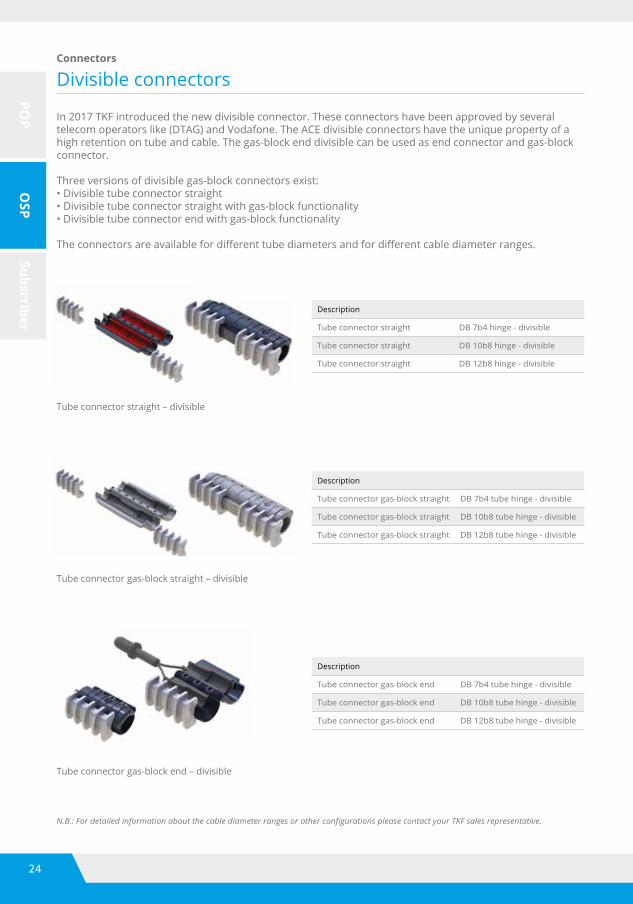
Divisible connectorsConnectors
In 2017 TKF introduced the new divisible connector. These connectors have been approved by several telecom operators like (DTAG) and Vodafone. The ACE divisible connectors have the unique property of a high retention on tube and cable. The gas-block end divisible can be used as end connector and gas-block connector.
Three versions of divisible gas-block connectors exist:• Divisible tube connector straight• Divisible tube connector straight with gas-block functionality• Divisible tube connector end with gas-block functionality
Theconnectorsareavailablefordifferenttubediametersandfordifferentcablediameterranges.
Tube connector straight – divisible
Tube connector gas-block straight – divisible
Tube connector gas-block end – divisible
Description
Tube connector straight DB 7b4 hinge - divisible
Tube connector straight DB 10b8 hinge - divisible
Tube connector straight DB 12b8 hinge - divisible
Description
Tube connector gas-block straight DB 7b4 tube hinge - divisible
Tube connector gas-block straight DB 10b8 tube hinge - divisible
Tube connector gas-block straight DB 12b8 tube hinge - divisible
Description
Tube connector gas-block end DB 7b4 tube hinge - divisible
Tube connector gas-block end DB 10b8 tube hinge - divisible
Tube connector gas-block end DB 12b8 tube hinge - divisible
N.B.: For detailed information about the cable diameter ranges or other configurations please contact your TKF sales representative.

25
POP
OSP
Subscriber
N.B.: For other configurations please contact your TKF sales representative.
The ACE 2-way and 4-way tube closures are divisible direct buried closures which can be used for:• Transition of tube to tube (same diameter)•Transitionoftubetodifferentdiametertube• Transition of several microtubes to tube• Transition of several minitubes to modular cable
Theclosureisusedforfibrenetworkmaintenanceandfibreortube blowing features.
The strain relief inlay parts are exchangeable, therefore it is possible to use one housing for several diameters and applications. A range of 25, 32, 40 and 50 mm are available for use with the closure housing.
Tube connectors are easy to install due to the length of the closure. The closure can be installed without any tooling.
TheACEMCtype5branch-offclosureisatwinshellre-openable that serves as mechanical protection when extending or branchingoffmultitubecables.Theclosureisappliedattheposition where the outer sheath of the multitube cable DB is removed and DI tubes are extended or branchedoffwithtubeconnectors.
The4ports(2portsonbothsides)canbeusedfordifferentdiameters:• 50 mm max (smaller diameters are 46, 39 and 33 mm)• 50 mm max (smaller diameters are 34, 30 and 17 mm)
The closure is sand-tight. A metal bracket inside the closure is usedtofixcableswithhoseclips.
Tubeclosuresareanexcellentandcosteffectivesolutiontobranch-offandconnectductandblownfibretubes.Thetubeclosuresaresuitablefordifferenttypesandsizesoftubesandducts.
Tube Management ClosuresTube closures
Art. number ACE code Description
530224 CL-R2-T-40-40 2-way tube closure in-line 40 mm
530225 CL-R4-T-40-40-40-40 4-way tube closure in-line 40 mm
530229 CLAC-RX-CL0325 Tube closure clamp 25 mm
530228 CLAC-RX-CL0332 Tube closure clamp 32 mm
530226 CLAC-RX-CL0350 Tube closure clamp 50 mm
Art. number ACE code Description
530332 CL-5A-T Tubemanagementclosurebranch-offclosureMCtype5black
530345 CL-5A-T-P Tubemanagementclosurebranch-offclosureMCtype5purple
26
POP
OSP
Subscriber
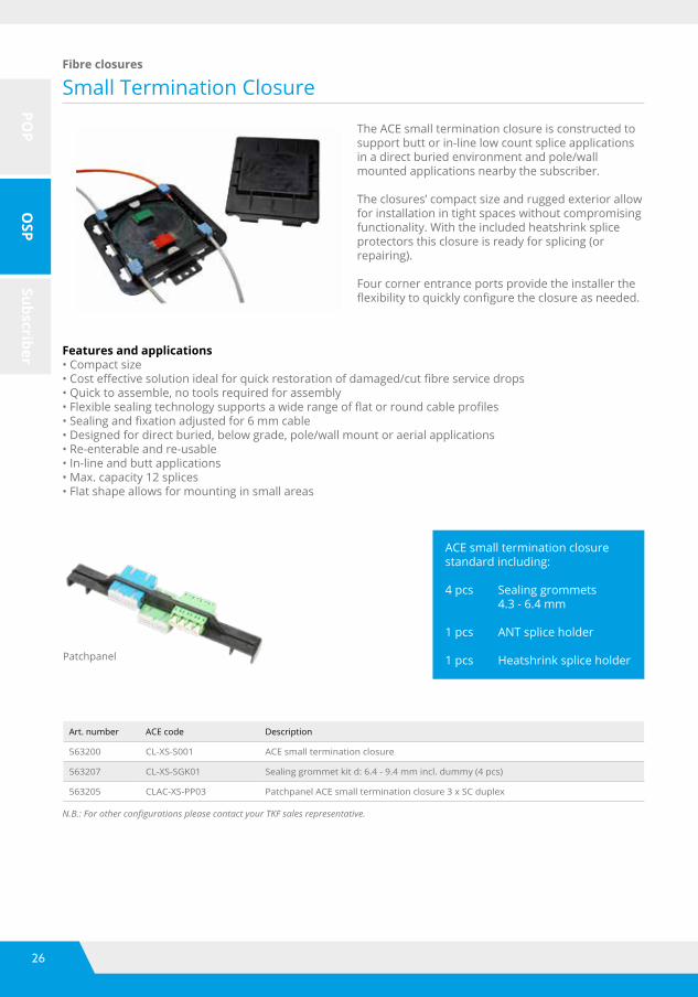
Small Termination ClosureFibre closures
The ACE small termination closure is constructed to support butt or in-line low count splice applications in a direct buried environment and pole/wall mounted applications nearby the subscriber.
The closures’ compact size and rugged exterior allow for installation in tight spaces without compromising functionality. With the included heatshrink splice protectors this closure is ready for splicing (or repairing).
Four corner entrance ports provide the installer the flexibilitytoquicklyconfiguretheclosureasneeded.
Features and applications• Compact size•Costeffectivesolutionidealforquickrestorationofdamaged/cutfibreservicedrops• Quick to assemble, no tools required for assembly•Flexiblesealingtechnologysupportsawiderangeofflatorroundcableprofiles•Sealingandfixationadjustedfor6mmcable• Designed for direct buried, below grade, pole/wall mount or aerial applications• Re-enterable and re-usable• In-line and butt applications• Max. capacity 12 splices• Flat shape allows for mounting in small areas
N.B.: For other configurations please contact your TKF sales representative.
Art. number ACE code Description
563200 CL-XS-S001 ACE small termination closure
563207 CL-XS-SGK01 Sealing grommet kit d: 6.4 - 9.4 mm incl. dummy (4 pcs)
563205 CLAC-XS-PP03 Patchpanel ACE small termination closure 3 x SC duplex
ACE small termination closure standard including: 4 pcs Sealing grommets
4.3 - 6.4 mm
1 pcs ANT splice holder
1 pcs Heatshrink splice holderPatchpanel
27
POP
OSP
Subscriber
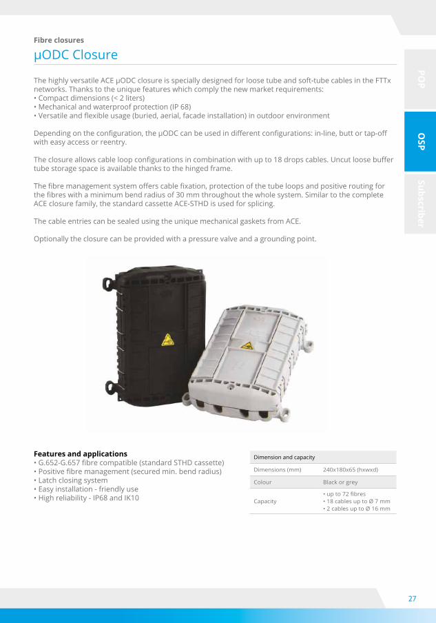
μODCClosureFibre closures
ThehighlyversatileACEμODCclosureisspeciallydesignedforloosetubeandsoft-tubecablesintheFTTxnetworks. Thanks to the unique features which comply the new market requirements:• Compact dimensions (< 2 liters)• Mechanical and waterproof protection (IP 68)•Versatileandflexibleusage(buried,aerial,facadeinstallation)inoutdoorenvironment
Dependingontheconfiguration,theμODCcanbeusedindifferentconfigurations:in-line,buttortap-offwith easy access or reentry.
Theclosureallowscableloopconfigurationsincombinationwithupto18dropscables.Uncutloosebuffertube storage space is available thanks to the hinged frame.
Thefibremanagementsystemofferscablefixation,protectionofthetubeloopsandpositiveroutingforthefibreswithaminimumbendradiusof30mmthroughoutthewholesystem.SimilartothecompleteACE closure family, the standard cassette ACE-STHD is used for splicing.
The cable entries can be sealed using the unique mechanical gaskets from ACE.
Optionally the closure can be provided with a pressure valve and a grounding point.
Features and applications•G.652-G.657fibrecompatible(standardSTHDcassette)•Positivefibremanagement(securedmin.bendradius)• Latch closing system• Easy installation - friendly use• High reliability - IP68 and IK10
Dimension and capacity
Dimensions (mm) 240x180x65 (hxwxd)
Colour Black or grey
Capacity•upto72fibres•18cablesuptoØ7mm•2cablesuptoØ16mm
28
POP
OSP
Subscriber
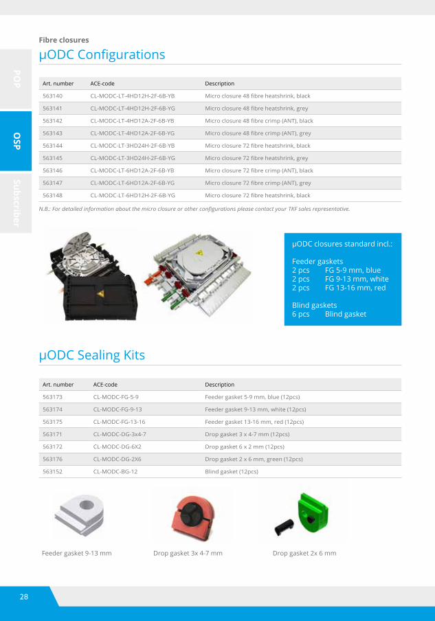
μODCConfigurations
μODCSealingKits
Fibre closures
Art. number ACE-code Description
563140 CL-MODC-LT-4HD12H-2F-6B-YB Microclosure48fibreheatshrink,black
563141 CL-MODC-LT-4HD12H-2F-6B-YG Microclosure48fibreheatshrink,grey
563142 CL-MODC-LT-4HD12A-2F-6B-YB Microclosure48fibrecrimp(ANT),black
563143 CL-MODC-LT-4HD12A-2F-6B-YG Microclosure48fibrecrimp(ANT),grey
563144 CL-MODC-LT-3HD24H-2F-6B-YB Microclosure72fibreheatshrink,black
563145 CL-MODC-LT-3HD24H-2F-6B-YG Microclosure72fibreheatshrink,grey
563146 CL-MODC-LT-6HD12A-2F-6B-YB Microclosure72fibrecrimp(ANT),black
563147 CL-MODC-LT-6HD12A-2F-6B-YG Microclosure72fibrecrimp(ANT),grey
563148 CL-MODC-LT-6HD12H-2F-6B-YG Microclosure72fibreheatshrink,black
N.B.: For detailed information about the micro closure or other configurations please contact your TKF sales representative.
μODCclosuresstandardincl.:
Feeder gaskets2 pcs FG 5-9 mm, blue2 pcs FG 9-13 mm, white2 pcs FG 13-16 mm, red
Blind gaskets6 pcs Blind gasket
Art. number ACE-code Description
563173 CL-MODC-FG-5-9 Feeder gasket 5-9 mm, blue (12pcs)
563174 CL-MODC-FG-9-13 Feeder gasket 9-13 mm, white (12pcs)
563175 CL-MODC-FG-13-16 Feeder gasket 13-16 mm, red (12pcs)
563171 CL-MODC-DG-3x4-7 Drop gasket 3 x 4-7 mm (12pcs)
563172 CL-MODC-DG-6X2 Drop gasket 6 x 2 mm (12pcs)
563176 CL-MODC-DG-2X6 Drop gasket 2 x 6 mm, green (12pcs)
563152 CL-MODC-BG-12 Blind gasket (12pcs)
Feeder gasket 9-13 mm Drop gasket 3x 4-7 mm Drop gasket 2x 6 mm
29
POP
OSP
Subscriber
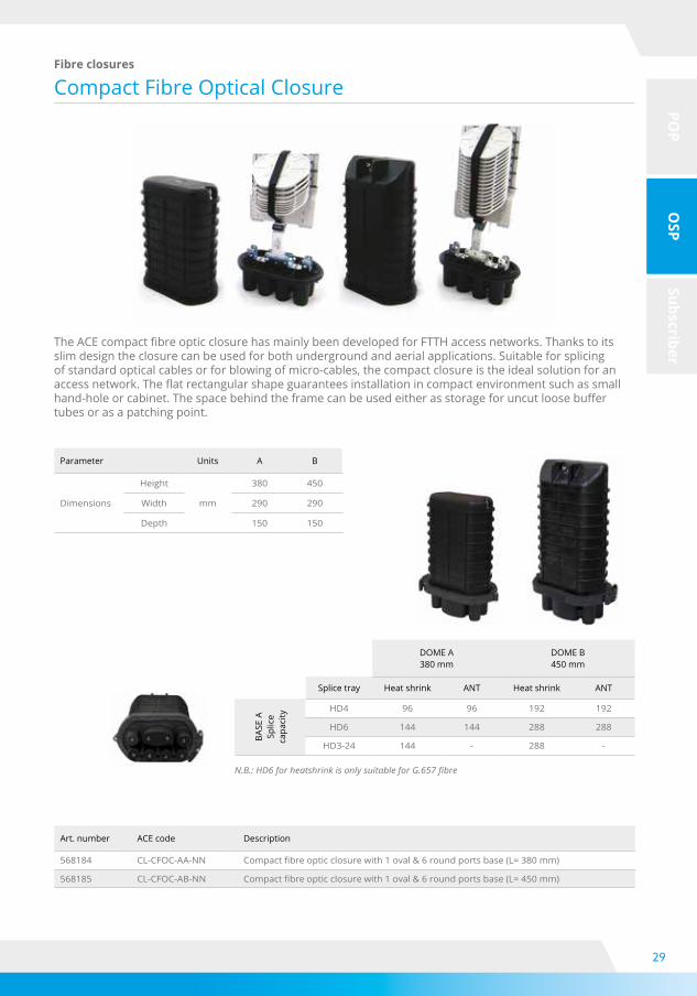
Compact Fibre Optical ClosureFibre closures
TheACEcompactfibreopticclosurehasmainlybeendevelopedforFTTHaccessnetworks.Thankstoitsslim design the closure can be used for both underground and aerial applications. Suitable for splicing of standard optical cables or for blowing of micro-cables, the compact closure is the ideal solution for an accessnetwork.Theflatrectangularshapeguaranteesinstallationincompactenvironmentsuchassmallhand-holeorcabinet.Thespacebehindtheframecanbeusedeitherasstorageforuncutloosebuffertubes or as a patching point.
Parameter Units A B
Dimensions
Height
mm
380 450
Width 290 290
Depth 150 150
DOME A380 mm
DOME B450 mm
Splice tray Heat shrink ANT Heat shrink ANT
BASE
A
Splic
e ca
paci
ty
HD4 96 96 192 192
HD6 144 144 288 288
HD3-24 144 - 288 -
N.B.: HD6 for heatshrink is only suitable for G.657 fibre
Art. number ACE code Description
568184 CL-CFOC-AA-NN Compactfibreopticclosurewith1oval&6roundportsbase(L=380mm)
568185 CL-CFOC-AB-NN Compactfibreopticclosurewith1oval&6roundportsbase(L=450mm)
30
POP
OSP
Subscriber
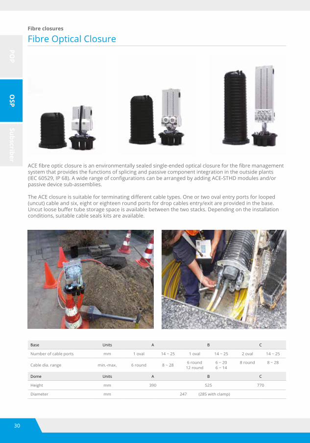
Fibre Optical ClosureFibre closures
ACEfibreopticclosureisanenvironmentallysealedsingle-endedopticalclosureforthefibremanagementsystem that provides the functions of splicing and passive component integration in the outside plants (IEC60529,IP68).AwiderangeofconfigurationscanbearrangedbyaddingACE-STHDmodulesand/orpassive device sub-assemblies.
TheACEclosureissuitableforterminatingdifferentcabletypes.Oneortwoovalentryportsforlooped(uncut) cable and six, eight or eighteen round ports for drop cables entry/exit are provided in the base. Uncutloosebuffertubestoragespaceisavailablebetweenthetwostacks.Dependingontheinstallationconditions, suitable cable seals kits are available.
Base Units A B C
Number of cable ports mm 1 oval 14 ~ 25 1 oval 14 ~ 25 2 oval 14 ~ 25
Cable dia. range min.-max. 6 round 8 ~ 286 round
12 round6 ~ 206 ~ 14
8 round 8 ~ 28
Dome Units A B C
Height mm 390 525 770
Diameter mm 247 (285 with clamp)

31
POP
OSP
Subscriber
Fibre Optical ClosureFibre closures
Art. number Ace code Description
568160 CL-FOC-AA-NN Closurewith1oval&6roundportsbase(L=390mm)
568161 CL-FOC-AB-NN Closurewith1oval&6roundportsbase(L=525mm)
568162 CL-FOC-AC-NN Closurewith1oval&6roundportsbase(L=770mm)
568164 CL-FOC-BB-NN Closurewith1oval&18roundportsbase(L=525mm)
568165 CL-FOC-BC-NN Closurewith1oval&18roundportsbase(L=770mm)
568167 CL-FOC-CB-NN Closurewith2oval&8roundportsbase(L=525mm)
568169 CL-FOC-CC-NN Closurewith2oval&8roundportsbase(L=770mm)
Dome A390 mm
Dome B525 mm
Dome C770 mm
Splice tray Heat shrink ANT Heat shrink ANT Heat shrink ANT
Base A 247 mm
-285 mm with clamp
HD4 288 288 576 576 1056 1056
HD6 432 432 960 960 1584 1584
HD3-24 432 - 960 - 1584 -
Splice tray Heat shrink ANT Heat shrink ANT Heat shrink ANT
Base B 247 mm
-285 mm with clamp
HD4 288 288 576 576 - -
HD6 432 432 960 960 - -
HD3-24 432 - 960 - - -
Splice tray Heat shrink ANT Heat shrink ANT Heat shrink ANT
Base C 247 mm
-285 mm with clamp
HD4 - - 480 720 1056 1056
HD6 - - 720 720 1584 1584
HD3-24 - - 720 1584 N.B.: HD6 for heat shrink is only suitable for G.657 fibre

32
POP
OSP
Subscriber
Demarcation Optical ClosureFibre closures
The ACE demarcation and compact demarcation closure are environmentally sealed single-ended optical closures to manage the demarcation point from the operator network ends and the customer’s on-premiseswiring.Thesedemarcationclosuresaretheidealsolutionforaflexiblecarrierdemarcationpointwith dimensions and splice/connection capacities suitable to satisfy all requests.
Large splice capacity HD trays used together with compact and positive design allows that extra carriers/customerscanbeconnectedtothebackbonesideofthenetworkwithoutaffectingother,alreadyconnectedcarriers/customers.TheseclosureshavethesamefeaturesandbenefitsofstandardACEfibreoptic closures (IEC 60529, IP 68). Also the same sealing methods can be applied. Due to the possibility to integrate splitter assemblies in the HD splice trays, makes it possible to transform an demarcation closure into an distribution and demarcation point.
DOC - AA
SC capability max. 32 SC connections
LC capability max. 64 LC connections
Heat shrink ANT
HD4 144 144
HD6 216 216
HD3-24 216 -
CDOC - AA
SC capability max. 9 SC connections
LC capability max. 18 LC connections
Heat shrink ANT
HD4 48 48
HD6 72 72
HD3-24 72 -
Art. number Ace code Description
568205 CL-DOC-AA-NN Demarcationopticclosurewith1oval&6roundportsbase(L=390mm)
568209 CL-CDOC-AB-NN Compactdemarcationopticclosurewith1oval&6roundportsbase(L=380mm)
33
POP
OSP
Subscriber
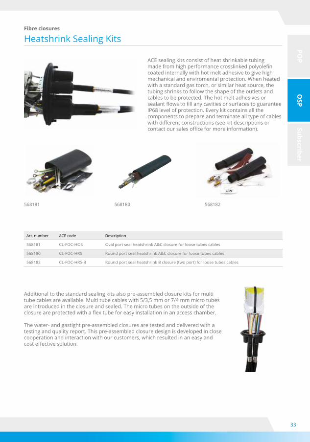
Heatshrink Sealing KitsFibre closures
ACE sealing kits consist of heat shrinkable tubing madefromhighperformancecrosslinkedpolyolefincoated internally with hot melt adhesive to give high mechanical and enviromental protection. When heated with a standard gas torch, or similar heat source, the tubing shrinks to follow the shape of the outlets and cables to be protected. The hot melt adhesives or sealantflowstofillanycavitiesorsurfacestoguaranteeIP68 level of protection. Every kit contains all the components to prepare and terminate all type of cables withdifferentconstructions(seekitdescriptionsorcontactoursalesofficeformoreinformation).
568181 568180 568182
Art. number ACE code Description
568181 CL-FOC-HOS Oval port seal heatshrink A&C closure for loose tubes cables
568180 CL-FOC-HRS Round port seal heatshrink A&C closure for loose tubes cables
568182 CL-FOC-HRS-B Round port seal heatshrink B closure (two port) for loose tubes cables
Additional to the standard sealing kits also pre-assembled closure kits for multi tube cables are available. Multi tube cables with 5/3,5 mm or 7/4 mm micro tubes are introduced in the closure and sealed. The micro tubes on the outside of the closureareprotectedwithaflextubeforeasyinstallationinanaccesschamber.
The water- and gastight pre-assembled closures are tested and delivered with a testing and quality report. This pre-assembled closure design is developed in close cooperation and interaction with our customers, which resulted in an easy and costeffectivesolution.

34
POP
OSP
Subscriber
Mechanical Sealing KitsFibre closures
Each seal is re-accessible and allows easy and fast installation of any cable even when other cables are installed in the same port. Whatever the construction of the cable, all sealing kits allow to terminate either the aramid yarns or the strength member in order to provide a good resistance to accidental forces. Depending from the size of the cable, each sealing kit permits the entrance of one or more cables in the same port even in differentsequences.Thesealing(IEC529andIP68)is guaranteed in all circumstances.
568174
568173
568175
568170
568176
568177
568208
568172
Art. number ACE-Code DescriptionCable diameter (mm)
Min. Max.
568174 CL-FOC-MOS-2x20 Mechanical oval seal 2 x 20 mm 10 20
568175 CL-FOC-MOS-4x10 Mechanical oval seal 4 x 10 mm 5 10
568176 CL-FOC-MRS-1x20 Mechanical round seal 1 x 20 mm 12 20
568173 CL-FOC-MRS-2x12 Mechanical round seal 2 x 12 mm 8 12
568170 CL-FOC-MRS-6x8 Mechanical round seal 6 x 8 mm 5 8
568177 CL-FOC-MRS-8x6,4 Mechanical round seal 8 x 6,4 mm 3 6,4
568172 CL-FOC-MRS-16x3 Mechanical round seal 16 x 3 mm 0 3
568208 CL-FOC-MRS-4x10 Mechanical round seal 4x10 mm 8 10
N.B.: Indicative values depending on cables construction
35
POP
OSP
Subscriber
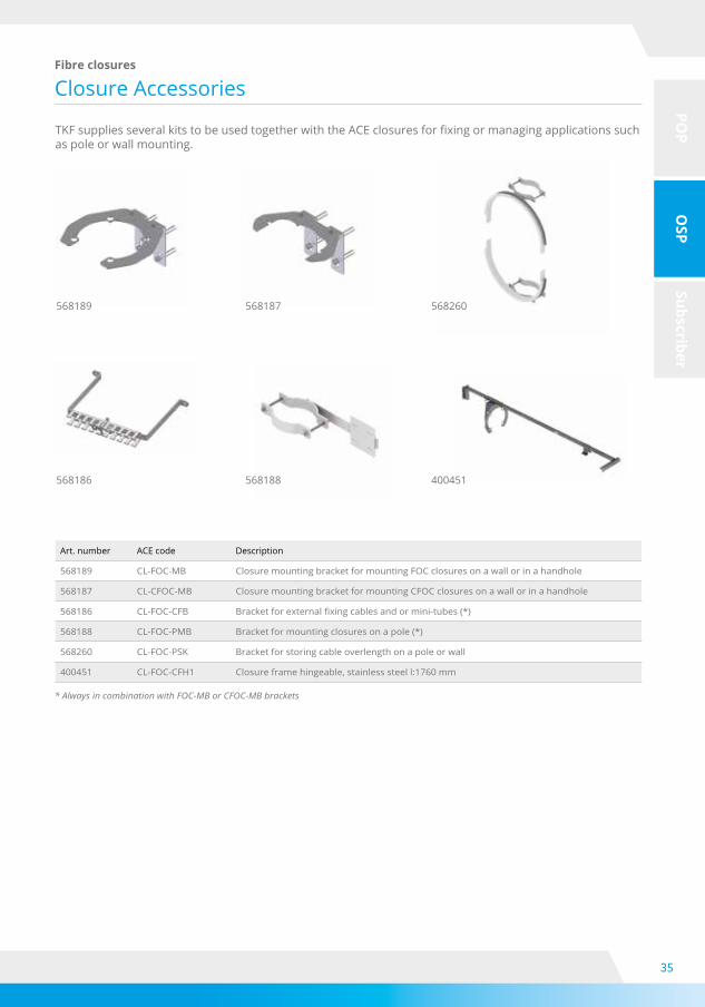
Closure AccessoriesFibre closures
568189
TKFsuppliesseveralkitstobeusedtogetherwiththeACEclosuresforfixingormanagingapplicationssuchas pole or wall mounting.
Art. number ACE code Description
568189 CL-FOC-MB Closure mounting bracket for mounting FOC closures on a wall or in a handhole
568187 CL-CFOC-MB Closure mounting bracket for mounting CFOC closures on a wall or in a handhole
568186 CL-FOC-CFB Bracketforexternalfixingcablesandormini-tubes(*)
568188 CL-FOC-PMB Bracket for mounting closures on a pole (*)
568260 CL-FOC-PSK Bracket for storing cable overlength on a pole or wall
400451 CL-FOC-CFH1 Closure frame hingeable, stainless steel l:1760 mm
* Always in combination with FOC-MB or CFOC-MB brackets
568187
568188
568260
400451568186

36
POP
OSP
Subscriber
ACEcabStreet Cabinets
The ACEcab consists of a fully assembled cabinet in a modular setup. The outer shell of the cabinet is made of reinforced polycarbonate, which is an extremely durable material. The inner construction is designed for an easy and fast installation for various applications. Themodularityoffersoptionstouseplugandplaysplitters,patchfield withdifferentadaptersandsingleelementorsinglecircuitsplicing.
The primary use of the ACEcab series is to form the last distribution andmanipulationpointinafibrenetworkofburied(multitube)cables.Highfibrecountcablescomeinfromthecentralofficewhichare connected to the cables that run to the individual premises of ahouseorbusiness.Therearedifferentcableentriesavailableandsufficientspaceforclippingdirectburiedtubestothebackframe.
Features and applications• Attractive modular design• Swing frame technology for easy access• Modular splice system for single circuit / single element• Tube management / storage• Plug and play splitter / splice splitter solutions• Minimum installation time•Securedfibreandcablerouting• Modular components in the entire housing (building blocks)• IP54 protection
Parameter Units ACEcab 4 (HD) ACEcab 8 (HD)
Dimensions
Height(*)
mm
998 998
Width 442 754
Depth 310 310
Description
Splices(crimp)
Terminations LC / SC
No. of hard-case splitters
No. of feeder cables
No. of drop cables
ACEcab 4 1224 288 / 144 5* 4 48
ACEcab 4 HD 1152 0 0* 8 96
ACEcab 8 2448 576 / 288 10* 8 96
ACEcab 8 HD 2304 0 0* 16 192
(*) Excl. sockel heigth above ground 400 mm
* Amounts and splitter ratios of small case splitters depend on the configuration. Please contact your TKF sales representative.

37
POP
OSP
Subscriber
Next Generation Box
NGB2 Splice
Termination boxes
Features and applications• Cable seal kits and accessories for easier installation• Compatible with the most common cables types• OSP Drop cable terminations for access networks•Telecommunicationenclosureforflooropticaldistribution• Customized compact environmental protection
The ACE next generation boxes are compact wall enclosures developed for the PON and P2P FTTH network architecture. The boxes are designed to operate in category C (controlled), category G (outdoor ground level) and category A (aerial) as characterized by IEC 61753-1, hence for indoor and outdoor applications like customer’s premises, basement building, telecommunications equipment rooms, pole mountings, external wall sites etc. The protection level against water and dust is IP55. The boxes can accommodate uncutloopedfibrecableanditispossibletoterminateandsealdifferentcableconstructionbyacompleterange of accessories. Versions with lock are available for improved security against unauthorized openings.
Dimensions (mm) NGB2 NGB1 NGB
Height 330 255 170
Width 216 165 110
Depth 125 110 70
Max. portentries(in+out)
Splice capacity
HD3-24 HD6 HD4
2 144 144 96
The splice version of the wall box is capable of accommodating the fibersofanuncutloopedopticalfibrecable.Itispossibletoterminatedifferentcabletypesandconstructions
38
POP
OSP
Subscriber
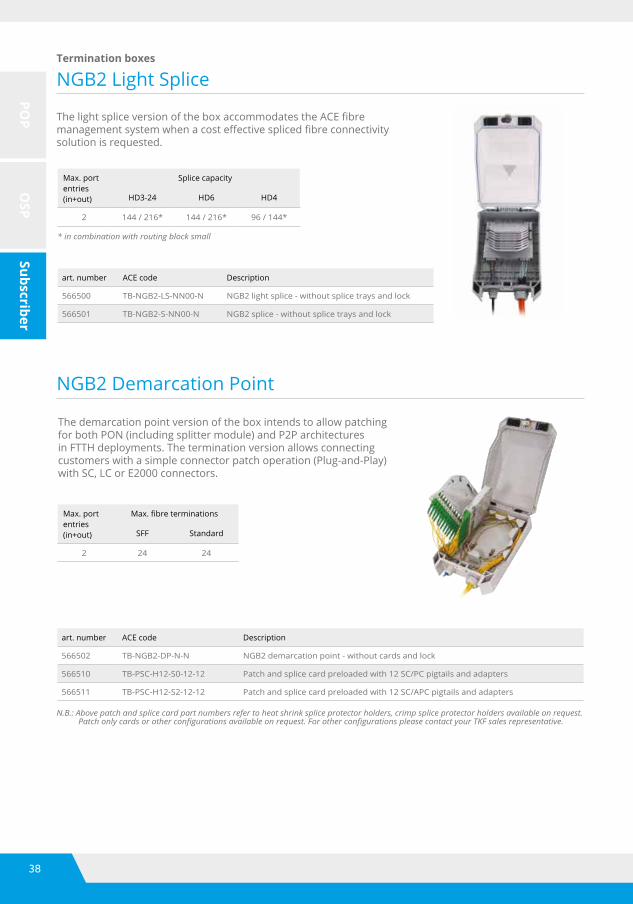
NGB2 Light Splice
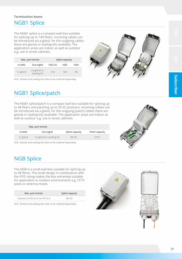
NGB2 Demarcation Point
Termination boxes
art. number ACE code Description
566500 TB-NGB2-LS-NN00-N NGB2 light splice - without splice trays and lock
566501 TB-NGB2-S-NN00-N NGB2 splice - without splice trays and lock
ThelightspliceversionoftheboxaccommodatestheACEfibremanagementsystemwhenacosteffectivesplicedfibreconnectivitysolution is requested.
* in combination with routing block small
Max. portentries(in+out)
Splice capacity
HD3-24 HD6 HD4
2 144 / 216* 144 / 216* 96 / 144*
Max. portentries(in+out)
Max.fibreterminations
SFF Standard
2 24 24
The demarcation point version of the box intends to allow patching for both PON (including splitter module) and P2P architectures in FTTH deployments. The termination version allows connecting customers with a simple connector patch operation (Plug-and-Play) with SC, LC or E2000 connectors.
N.B.: Above patch and splice card part numbers refer to heat shrink splice protector holders, crimp splice protector holders available on request. Patch only cards or other configurations available on request. For other configurations please contact your TKF sales representative.
art. number ACE code Description
566502 TB-NGB2-DP-N-N NGB2 demarcation point - without cards and lock
566510 TB-PSC-H12-S0-12-12 Patch and splice card preloaded with 12 SC/PC pigtails and adapters
566511 TB-PSC-H12-S2-12-12 Patch and splice card preloaded with 12 SC/APC pigtails and adapters
39
POP
OSP
Subscriber
NGB1 Splice
NGB1 Splice/patch
NGB Splice
Termination boxes
N.B.: Glands and sealing kits have to be ordered separately.
N.B.: Glands and sealing kits have to be ordered separately.
N.B.: Glands and sealing kits have to be ordered separately.
The NGB1 splice is a compact wall box suitable forsplicingupto144fibers.Incomingcablescanbe introduced via a gland, for the outgoing cables there are glands or sealing kits available. The application areas are indoor as well as outdoor e.g. use in street cabinets.
The NGB1 splice/patch is a compact wall box suitable for splicing up to48fibersandpatchingupto24SCpositions.Incomingcablescanbe introduced via a gland, for the outgoing (patch) cables there are glands or sealing kits available. The application areas are indoor as well as outdoor e.g. use in street cabinets.
The NGB is a small wall box suitable for splicing up to48fibres.Thesmalldesignincombinationwiththe IP55 rating makes the box extremely suitable for application in outdoor environments e.g. CCTV poles or antenna masts.
Max. port entries Splice capacity
In (left) Out (right) HD3-24 HD6 HD4
1x gland2x gland or sealing kit
144 144 96
Max. port entries
In (left) Out (right) Splice capacity Patch capacity
1x gland 2x gland or sealing kit 48 HS 24 SC
Max. port entries Splice capacity
Glands 2x PG16 or 3x PG13.5 48 HS
40
POP
OSP
Subscriber
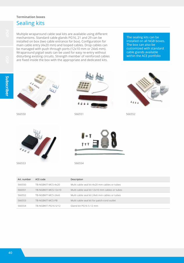
Sealing kitsTermination boxes
Art. number ACE code Description
566550 TB-NGBKIT-MCS-4x20 Multi cable seal kit 4x20 mm cables or tubes
566551 TB-NGBKIT-MCS-12x10 Multi cable seal kit 12x10 mm cables or tubes
566552 TB-NGBKIT-MCS-24x6 Multi cable seal kit 24x6 mm cables or tubes
566553 TB-NGBKIT-MCS-PB Multi cable seal kit for patch-cord outlet
566554 TB-NGBKIT-PG16-5/12 Gland kit PG16 5-12 mm
Multiplewraparoundcablesealkitsareavailableusingdifferentmechanisms. Standard cable glands PG16, 21 and 29 can be installedonbox(twocableentranceforbox).Configurationformain cable entry (4x20 mm) and looped cables. Drop cables can be managed with push through ports (12x10 mm or 24x6 mm). Wraparound pigtail seals can be used for easy re-entry without disturbing existing circuits. Strength member of reinforced cables arefixedinsidetheboxwiththeappropriateanddedicatedkits.
The sealing kits can beinstalled on all NGB boxes.The box can also becustomized with standardcable glands available within the ACE portfolio
566550
566553
566551
566554
566552
41
POP
OSP
Subscriber
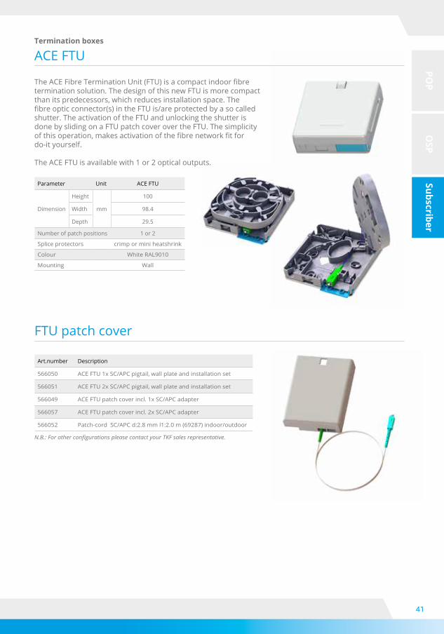
ACE FTU
FTU patch cover
Termination boxes
Art.number Description
566050 ACE FTU 1x SC/APC pigtail, wall plate and installation set
566051 ACE FTU 2x SC/APC pigtail, wall plate and installation set
566049 ACE FTU patch cover incl. 1x SC/APC adapter
566057 ACE FTU patch cover incl. 2x SC/APC adapter
566052 Patch-cord SC/APC d:2.8 mm l1:2.0 m (69287) indoor/outdoor
Parameter Unit ACE FTU
Dimension
Height
mm
100
Width 98.4
Depth 29.5
Number of patch positions 1 or 2
Splice protectors crimp or mini heatshrink
Colour White RAL9010
Mounting Wall
N.B.: For other configurations please contact your TKF sales representative.
TheACEFibreTerminationUnit(FTU)isacompactindoorfibretermination solution. The design of this new FTU is more compact than its predecessors, which reduces installation space. The fibreopticconnector(s)intheFTUis/areprotectedbyasocalledshutter. The activation of the FTU and unlocking the shutter is done by sliding on a FTU patch cover over the FTU. The simplicity ofthisoperation,makesactivationofthefibrenetworkfitfor do-it yourself.
The ACE FTU is available with 1 or 2 optical outputs.

42
POP
OSP
Subscriber
ACE Customer OutletTermination boxes
Newoutletsforfibreopticcablingforresidentialand commercial buildings. The ACE customer outletsareacompletelineofferingmodernsolutionssuitableforseveralconfigurationsuch as multi port, splicing and hybrid. The low profiledesignandhorizontalverticalorientationoftheopticaloutletsofferaverycleanvisualappearance while protecting the cable connection withrespectofminimumbendradiusofthefibre. •max.4fibers(566007) •max.8fibers(566008) •max.16fibers(566009)
These customer outlets are only for indoor use and can be mounted on a wall.
Description ACE customer outlet performance
Feature 566007 566008 566009
Dimensions (lxwxh) (mm) 130 x 80 x 25 130 x 80 x 45 130 x 80 x 45
Cable entry rear
left
right
top
Labelling
Diameter input cable (mm) 1.8 - 7.0 1.8 - 7.0 1.8 - 7.0
Splice capacity ANT 4
HS 4
Patch capacity LC 4 8 16
SC 2 4 8
RJ45 1
Access protection
Art. number ACE code Description
566007 TB-SP2-C1-02S ACE customer outlet 2x SC; 4 splice positions + WDM position
566008 TB-SV1-C0-02T ACE customer outlet RJ45, SC-duplex LC-quad
566009 TB-SV1-C0-08S ACE customer outlet SC-duplex LC-quad
566008
566007
566009
566007
566009
566008
43
POP
OSP
Subscriber
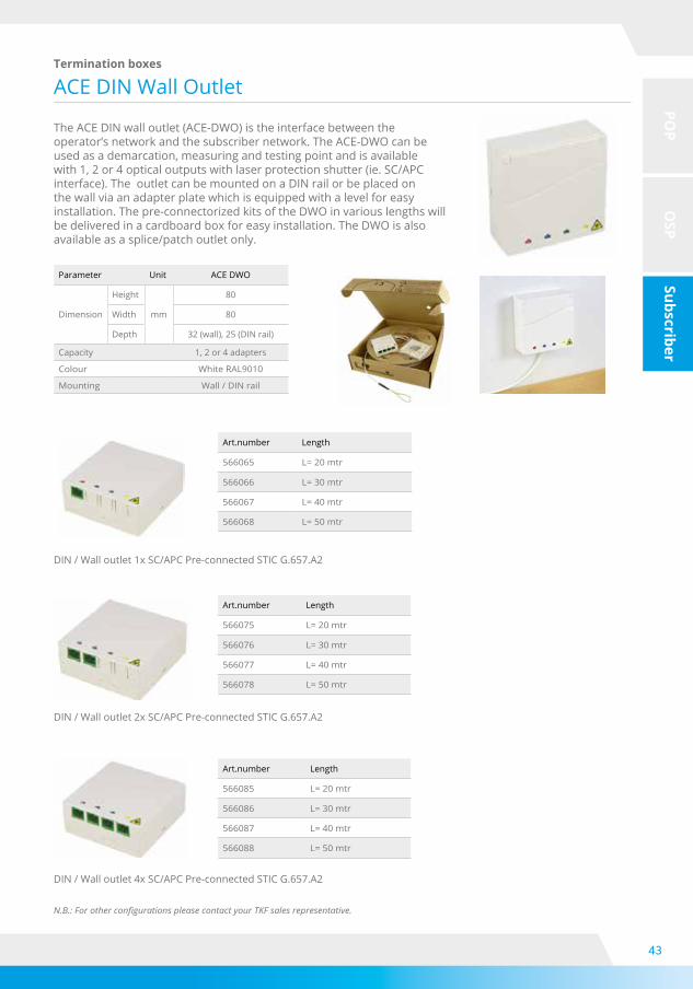
ACE DIN Wall OutletTermination boxes
The ACE DIN wall outlet (ACE-DWO) is the interface between the operator’s network and the subscriber network. The ACE-DWO can be used as a demarcation, measuring and testing point and is available with 1, 2 or 4 optical outputs with laser protection shutter (ie. SC/APC interface). The outlet can be mounted on a DIN rail or be placed on the wall via an adapter plate which is equipped with a level for easy installation. The pre-connectorized kits of the DWO in various lengths will be delivered in a cardboard box for easy installation. The DWO is also available as a splice/patch outlet only.
Parameter Unit ACE DWO
Dimension
Height
mm
80
Width 80
Depth 32 (wall), 25 (DIN rail)
Capacity 1, 2 or 4 adapters
Colour White RAL9010
Mounting Wall / DIN rail
DIN / Wall outlet 1x SC/APC Pre-connected STIC G.657.A2
DIN / Wall outlet 2x SC/APC Pre-connected STIC G.657.A2
DIN / Wall outlet 4x SC/APC Pre-connected STIC G.657.A2
Art.number Length
566065 L=20mtr
566066 L=30mtr
566067 L=40mtr
566068 L=50mtr
Art.number Length
566075 L=20mtr
566076 L=30mtr
566077 L=40mtr
566078 L=50mtr
Art.number Length
566085 L=20mtr
566086 L=30mtr
566087 L=40mtr
566088 L=50mtr
N.B.: For other configurations please contact your TKF sales representative.

44
POP
OSP
Subscriber
ACE DIN Rail ModuleTermination boxes
The ACE DIN rail module (ACE-DRM) is the interface between the operator’s network and the subscriber network. The ACE-DRM can be used as a demarcation, measuring and testing point and is available with 1, 2 or 4optical outputs with laser protection shutter (ie. SC/APC interface). The module is special developed for installation on a DIN rail, inside a customer central distribution point. The DRM is pre-connectorized available in various lengths and will be delivered in a cardboard box for easy installation.
Parameter Unit ACE DRM
Dimension
Height
mm
88
Width 17.8 (1f & 2f) 35.8 (4f)
Depth 60
Capacity 1,2 or 4 adapters
Colour White RAL9010
Mounting DIN rail
DIN-rail Module 1x SC/APC STIC 1 x SM G.657.A2
DIN-rail Module 2x SC/APC STIC 2 x SM G.657.A2
DIN-rail Module 4x SC/APC STIC 4 x SM G.657.A2
Art.number Length
566105 L=20mtr
566106 L=30mtr
566107 L=40mtr
566108 L=50mtr
Art.number Length
566115 L=20mtr
566116 L=30mtr
566117 L=40mtr
566118 L=50mtr
Art.number Length
566125 L=20mtr
566126 L=30mtr
566127 L=40mtr
566128 L=50mtr
N.B.: For other configurations please contact your TKF sales representative.

45
POP
OSP
Subscriber
ACE Splice Tray High DensitySplice trays
The high density splicing module (ACE-STHD) is an essential part of the ACE product range. These modulesallowincreasedfibrecapacityinanyoftheACE shelves, closures and boxes, ensuring full bend radiuscontrolandtotalfibremanagement.
The module consists of a number of trays for storing and protecting splices, and a routing plate whichguidesthefibersinandoutofthetray.Theconcept uses a base plate allowing more trays in thefootprint,increasingfibrecapacity.Highquality,total modularity and ease of installation are the key factors of the ACE-STHD splice system.
Parameter ACE-STHD
Loop-back facility Yes
Material ABS-PC
Flammability rating UL-94 V0
Colour RAL 7035
Art. NumberModule
TypeSpliceTray
PackSplice
568155STHD-4H
12HS6 mm
48
568154STHD-3H
24HS8 mm
72
568151STHD-6H
8HS4 mm
48
568148STHD-2H
8HS4 mm
16
Art. NumberModule
TypeSpliceTray
PackSplice
568143STHD-6H/12
12HS4 mm
72
568153STHD-4A
12ANT6 mm
48
568150STHD-6A
12ANT4 mm
72
568152STHD-2A
12ANT4 mm
24

46
POP
OSP
Subscriber
Hard Case Splitters
The hard case splittes can be mounted in a splitter shelf. Up to 23 splitters can be housed in a 3HU splitter shelf. The splitter shelf can be mounted in a 19” frame.
For guidance of the 2.0 mm cords it is strongly recommended to add a 1HU patch-cord management panel on top and under the splitter shelf.
PLC Splitters single mode
Small Case Splitters
Splitters
Planar Lightwave Circuit (PLC) is a manufacturing process for splitters. It concerns a waveguide array that is applied to a silica chip by using a photolithographic masking process. PLC splitters are available in several types.Tosimplifytheselectiononecandistinguish:hardcasesplittersfordistributionoffibrecordsandsmallcasesplittersfordistributionof(buffered)fibers.Bothtypesareavailableina1to n split ratio and an 2 to n split ratio. All splitters perform excellent in indoor and outside plant conditions.
Thesmallcasesplittersareavailablewith250µmand900µmbufferedfibers.Thesecanbeintegratedinthe ACE splice tray range for use in closures, boxes, racks, shelves etc.
250 µm module 900 µm module

47
POP
OSP
Subscriber
Ratio Unit 1 x 2 1 x 4 1 x 8 1 x 16 1 x 32 1 x 64
Operating wavelength nm 1260 - 1650
Insertion loss dB ≤4.0 ≤7.2 ≤10.2 ≤13.7 ≤17.0 ≤20.6
Loss uniformity dB ≤0.5 ≤0.6 ≤0.8 ≤1.2 ≤1.5 ≤2.0
Polarization dependent loss dB ≤0.2 ≤0.2 ≤0.2 ≤0.3 ≤0.3 ≤0.4
Return loss dB ≥55
Directivity dB ≥55
Temperature stability -40 ~ +85 °C dB ≤0.5
Package dimension (l x w x h) - 250 μm module
mm 40 x 4 x 4 40 x 4 x 4 40 x 4 x 4 50 x 4 x 4 50 x 7 x 4 60 x 12 x 4
Package dimension (l x w x h) - 900 μm module
mm 60 x 7 x 4 60 x 7 x 4 60 x 7 x 4 60 x 12 x 4 80 x 20 x 6 100 x 40 x 6
Package dimension (l x w x h) - 2.0 mm module
mm 100 x 80 x 10 100 x 80 x 10 100 x 80 x 10 100 x 105 x 18 100 x 105 x 18 100 x 105 x 18
Ratio Unit 2 x 2 2 x 4 2 x 8 2 x 16 2 x 32 2 x 64
Operating wavelength nm 1260 - 1650
Insertion loss dB ≤4.2 ≤7.4 ≤10.8 ≤14.0 ≤17.5 ≤21.0
Loss uniformity dB ≤1.0 ≤1.5 ≤1.5 ≤2.0 ≤2.0 ≤2.5
Polarization dependent loss dB ≤0.3 ≤0.3 ≤0.3 ≤0.3 ≤0.3 ≤0.5
Return loss dB ≥55
Directivity dB ≥55
Temperature stability -40 ~ +85 °C dB ≤0.5
Package dimension (l x w x h) - 250 μm module
mm 40 x 4 x 4 50 x 4 x 4 50 x 4 x 4 50 x 4 x 4 60 x 7 x 4 60 x 12 x 4
Package dimension (l x w x h) - 900 μm module
mm 60 x 7 x 4 60 x 7 x 4 60 x 7 x 4 60 x 12 x 4 80 x 20 x 6 100 x 40 x 6
Package dimension (l x w x h) - 2.0 mm module
mm 100 x 80 x 10 100 x 80 x 10 100 x 80 x 10 100 x 105 x 18 100 x 105 x 18 100 x 105 x 18
Specified without connectors. Add an additional 0.3 dB loss per connector.
N.B.: For detailed information about the splitters please contact your TKF sales representative.
561456 - Splitter shelf 3HU 19” 561911 - Patch-cord guide panel 1HU 19”
Specifications
Splitters

48
POP
OSP
Subscriber
Pigtails
Patch-cords
Adapters
Pigtails, patch-cords and adapters
Pigtailsareopticalfibrecordsmostlyconsistingofabarefibrewithasecondary coating and terminated at one side by an optical connector. Due to its limited mechanical resistance pigtails are commonly used in a controlled environment, for example in a patch shelf or splice tray.
Description
Cable type Drybuffer“Easystrip”
Diameter (mm) 0.9
IL grade IEC 61753 grade B, C
RL grade IEC 61753 grade 1, 2
Connector type LC/(A)PC, SC/(A)PC, E2000/APC, FC/(A)PC
Connector interface IEC-61754
Colour IEC 60304 / VDE 0888-3
Environmental class U - Uncontrolled environment IEC 61753
Description
Cable type Simplex, duplex
Diameter (mm) 1.2, 1.6, 2.0
IL grade IEC 61753 grade B, C
RL grade IEC 61753 grade 1, 2
Connector type LC/(A)PC, SC/(A)PC, E2000/APC, FC/(A)PC
Connector interface IEC-61754
Colour Yellow
Environmental class U - Uncontrolled environment IEC 61753
Patch-cordsareopticalfibrecordswithaconnectoronbothsides.Thefibrecordisadrybufferedopticalfibresurroundedbyreinforcement(aramidyarns)andanoutersheath.Bothsimplex,duplexandoutdoorpatch-cords are available.
Adaptersarecouplingandalignmentcomponentsfor2ormorefibreopticconnectors.Theadaptersareclassifiedbytype,configuration,couplingmechanismandstyle.Inmostcasestheadaptersarepartofapatchshelforterminationbox.TheACEadaptersstandoutduetotheunique“one-piece”housingwhichguarenteesahighqualityandstablefibreopticconnection.Differentconfigurationsareavailable,e.g.simplex,duplex,quad,withorwithoutflangeetc.
N.B.: For the different pigtail, patch-cord and adapter types please contact your TKF sales representative.

49
POP
OSP
Subscriber
Cable AssembliesCable assemblies
TKFoffersawiderangeofpre-connectedcables,cablesprovidedwithanygivenopticalconnectors.Smart fan-out solutions together with a cunning packaging have been developed to achieve a product that allows a fast, reliable and convenient installation process.
N.B.: For detailed information about the cable assemblies please contact your TKF sales representative.
Pre-connectedfibreopticmodules
Pre-connectedDAC“Homerun”
Pre-connected cables
Pre-connected hybrid cable
Pre-connectedMDIC“Rapidroll”
Pre-connected MADC
Features and applications• Homerun and rapid roll solutions make fast and easy installation at the customer premises possible•Connectorsaremounteddirectlyonthefibrewithoutsplicing• Fan-out modules are equipped with 0.9 mm or 1.8 mm protective tubing• Pre-connected SFU can be blown directly out of the packaging (blister)•ThecableassembliescanbecombinedwithdifferentACEboxesortrays• Individual retention of every tube in the Fan-out module guarantees a secure installation

50
POP
OSP
Subscriber
House Entry KitHouse entry kits
The ACE house entry kit is suitable for above ground and buried applications on walls following DIN 18195-4. The set includes all components for both installation options. Tubes and cables from 2 - 14 mm can be inserted. Maximum wall thickness up to 600 mm. The duct has a diameter of 20 mm, which requires a drilling of only 25 mm.
Gas-block connectors can be inserted in the housing.
Features and applications• Easy and fast installation• Uniform solution above ground and buried• Watertight following DIN 18195-4• Suitable for duct and cable diameters 2 - 14 mm• Gas-block connectors up to 14 mm can be inserted• One kit for above ground and buried applications• Small drillhole max. 25 mm• Click lock with seal• No additional tooling needed
Buried application Above ground application
Art. number ACE code Description
568930 MC-HE-01 House entry kit II including expansion resin

51
POP
OSP
Subscriber
Heat shrink Splice Protector
Crimp Splice Protector (ANT)
Consumables
Features and applications•Maximumdiameterofprimarycoatedfibre250μm• Storage temperature -30°C to +60°C• Processing temperature -5°C to +45°C
The heat shrink splice protector provides mechanical and environmental protection of fusion splices. The splice protector consists of a transparant shrinkable tube which contains meltable adhesive to encapsulate the splice. The stainless steel rod ensures a proper alignment and rigidity which protects the splice against mechanical damage and moisture.
Features and applications• Shrinkable temperature of the sleeve approx.
115°C to 125°C• Melting point of the adhesive approx. 75°C to 85°C• Hardness of metal pin > 400VH• Bellcore GR-1380 compliant• RoHS compliant•Fulllengthstrengthmemberfortotalfibresupport• Close dimensional tolerances• Fast shrink time
Art. number ACE code Description
401395 AC-SPH1 HeatshrinkspliceprotectorØ2.6mml:45mm(100pcs.)
401396 AC-SPH4 MiniheatshrinkspliceprotectorØ1.0mml:30mm(100pcs.)
The unprotected splice is embedded in the durable plastic compound, thus protecting it from environmental impacts. The splice protection consists of a single-part V-shaped metal base coated on both sideswithadurableplasticcompound.Thefibreopticsplice is mounted centrally in the splice protection after splicing and closed precisely by means of a splice protector press.
Art. number ACE code Description
401306 AC-SPA1 ANT splice protector (150 pcs.)
401334 AC-TOSP Splice protector press

52
POP
OSP
Subscriber
Cleaner penTools
TheACEportfoliooffershighperformancetoolstocleantheferruleendfaceofanopticalconnector.Twoversionsareavailable.CleanerpenforferruleendfaceØ1.25mmandacleanerpenforferruleendfaceØ2.50 mm.
The cleaner pen allows an one-step cleaning action directly at the PC and APC ferrule as well as through an adapter.
Art. number ACE code Description
430160 AC-TOCP-125 CleanerpenØ1.25mmLC/MUadapterandconnector
430161 AC-TOCP-250 CleanerpenØ2.50mmSC/FC/STadapterandconnector

53
Telecom headquarters
Tel. +31 (0)53 573 22 55 Fax +31 (0)53 573 21 85 [email protected]
Telecom France
Tel. +33 (0)16 454 12 82 Fax +33 (0)16 454 12 83 [email protected]
Telecom Germany
Tel. +49 (0)3328 33660 315 Fax +49 (0)3328 33660 311 [email protected]@ace-fibreoptic.com
Telecom Finland, Estonia, Latvia & Lithuania
Tel. +358 10 666 21 43 Tel. +31 (0)53 573 23 69
Fax +31 (0)53 573 23 06 [email protected]
Telecom Sweden
Tel. +46 (0)152 33 34 03 Tel. +31 (0)53 573 23 69
Fax +31 (0)53 573 23 06 [email protected]
TKF Telecom Services
Tel. +31 (0)162 475 800Service line +31 (0) 162 475 810
Fax +31 (0)162 455 751 [email protected]
TELECOM SOLUTIONS

54
MORE INFORMATIONThis catalogue contains information about product families. Information at item level can be requested viaourwebsiteandfromoursalesstaff.Thiscataloguehasbeencustomized.Informationaboutproductsthat are not included in this catalogue is available from our sales departments and can also be found on ourwebsitewww.ace-fibreoptic.com.
Please contact us for additional technical or commercial information. Contact information of our sales teams can be found on our website.
Subject to changesTKFreservestherighttomakechangestoitsproductspecificationsanditsrangeofproductswithoutinforming clients of this in advance.
DisclaimerThis catalogue is put together with great care. Nevertheless we can’t give any guarantees regarding the completeness, correctness or actualization of the information in this catalogue. No rights can be derived from the information as shown in this catalogue.
TKFisentitledtomodifythiscatalogueatalltimeswithimmediateeffectdueto(forexample)changes in legislation.
TKF can’t be held responsible for the content of this catalogue or the consequences of using the information including incorrect translation of the information by third parties.
© TKFAll rights reserved. Information in this catalogue may only be distributed with acknowledgement of the source.
Terms of deliveryOur general terms of delivery apply to all our deliveries including the products named in the catalogue. They are available via our website www.tkf.eu or from our sales departments.

55
NOTES

56
NOTES

57
NOTES

58
TKF FinlandTKF Finland
TKF Sweden
TKF GmbH
C&C Partners
TKF SAS
TKF Headquarters
58

Spinnerstraat 15
P.O. Box 6
NL-7480 AA Haaksbergen
The Netherlands
Cop
yrig
ht ©
TKF
• Ve
rsio
n 01
-201
7
Telephone: +31 (0)53 5732255
Email: [email protected]
Internet: www.tkf.eu
www.ace-fibreoptic.com