
Connection set-up and path assignment in wavelength division ...
20
US005999288A Ulllted States Patent [19] [11] Patent Number: 5,999,288 Ellinas et al. [45] Date of Patent: Dec. 7, 1999 [54] CONNECTION SET-UP AND PATH OTHER PUBLICATIONS ASSIGNMENT IN WAVELENGTH DIVISION _ _ _ _ MULTIPLEXED RING NETWORKS Multiwavelength Survivable R1ng Network Architectures, authored by AR Elrefaie and published in the Proceedings [75] Inventors; Georgios Nicos Ellinas, Long Island of the International Conference in Communications (ICC), City; Krishna Bala, New York, both of 1993 N.Y.; Gee-Kung Chang, Holmdel, NJ. _ _ _ _ Primary Examzner—Kn1fe-M1chael Negash [73] Assignee: Telcordia Technologies, Inc., Attorney) Agent» 0" F i" m—J0SePh Giordano Morristown, NJ. [57] ABSTRACT [21] Appl, No; 09/170,454 Techniques for physically implementing ?ber ring networks which achieve full mesh connectivity, such networks includ ing a 2-?ber WDM ring network composed of a clockwise ring and counter clockwise ring, and a 4-?ber WDM Self Healing Ring network. The number of wavelengths required [22] Filed: Oct. 12, 1998 Related US. Application Data [60] Provisional application NO‘ 6O/O73’433’ Feb‘ 2’ 1998' is derived for both odd and even number of nodes on the [51] Int. Cl? ................................................... .. H04B 10/20 ring- T9 physically set-up all required Connections in the [52] US. Cl. ........................................... .. 359/119; 359/124 network, Optimal Wavelength assignment algorithms are [58] Field of Search ................................... .. 359/119, 110, devised so that the Wavelength assignment between nodes 359/124; 370/452 on the ring is systematic and engenders full mesh connec tivity while avoiding any possible violation of the color [56] References Cited clash constraint. An illustrative algorithm uses a simple matrix approach for calculating the interconnection arrange U.S. PATENT DOCUMENTS mem 5,548,431 8/1996 Shin et al. ............................ .. 359/119 5,745,269 4/1998 Chawki et al. ....................... .. 359/119 17 Claims, 8 Drawing Sheets _ _ _ - ~_ - - _/ 901 NETWORK E931 ELEMENT I T 921 10m 'Lf CONTROLLER ELEMENT 904 , ,,__ 902 [910 [_ _912_ T NETWORK“ LOCAL I NETWORK I LOCAL “NETWORK MANAGER ‘ ELEMENT LOCAL CONTROLLER T NETWORK ELEMENT I
Transcript of Connection set-up and path assignment in wavelength division ...
US005999288A
Ulllted States Patent [19] [11] Patent Number: 5,999,288 Ellinas et al. [45] Date of Patent: Dec. 7, 1999
[54] CONNECTION SET-UP AND PATH OTHER PUBLICATIONS ASSIGNMENT IN WAVELENGTH DIVISION _ _ _ _
MULTIPLEXED RING NETWORKS Multiwavelength Survivable R1ng Network Architectures, authored by AR Elrefaie and published in the Proceedings
[75] Inventors; Georgios Nicos Ellinas, Long Island of the International Conference in Communications (ICC), City; Krishna Bala, New York, both of 1993 N.Y.; Gee-Kung Chang, Holmdel, NJ. _ _ _ _
Primary Examzner—Kn1fe-M1chael Negash [73] Assignee: Telcordia Technologies, Inc., Attorney) Agent» 0" F i" m—J0SePh Giordano
Morristown, NJ. [57] ABSTRACT
[21] Appl, No; 09/170,454 Techniques for physically implementing ?ber ring networks which achieve full mesh connectivity, such networks includ ing a 2-?ber WDM ring network composed of a clockwise ring and counter clockwise ring, and a 4-?ber WDM Self Healing Ring network. The number of wavelengths required
[22] Filed: Oct. 12, 1998
Related US. Application Data [60] Provisional application NO‘ 6O/O73’433’ Feb‘ 2’ 1998' is derived for both odd and even number of nodes on the
[51] Int. Cl? ................................................... .. H04B 10/20 ring- T9 physically set-up all required Connections in the [52] US. Cl. ........................................... .. 359/119; 359/124 network, Optimal Wavelength assignment algorithms are [58] Field of Search ................................... .. 359/119, 110, devised so that the Wavelength assignment between nodes
359/124; 370/452 on the ring is systematic and engenders full mesh connec tivity while avoiding any possible violation of the color
[56] References Cited clash constraint. An illustrative algorithm uses a simple matrix approach for calculating the interconnection arrange
U.S. PATENT DOCUMENTS mem
5,548,431 8/1996 Shin et al. ............................ .. 359/119
5,745,269 4/1998 Chawki et al. ....................... .. 359/119 17 Claims, 8 Drawing Sheets
_ _ _ - ~_ - - _/ 901
NETWORK E931 ELEMENT I
T 921 10m 'Lf
CONTROLLER
ELEMENT
904 , ,,__ 902
[910 [_ _912_ T NETWORK“ LOCAL I NETWORK I LOCAL “NETWORK
MANAGER ‘ ELEMENT
LOCAL CONTROLLER
T NETWORK ELEMENT I
U.S. Patent Dec. 7, 1999 Sheet 1 0f 8 5,999,288
FIG. 1
U.S. Patent
31 NODE
Dec. 7, 1999
FIG. 2A
1\ NODE
Sheet 2 0f 8
NODE
5,999,288
U.S. Patent Dec. 7, 1999 Sheet 3 0f 8 5,999,288
CLUCKWISE \
DIRECTION \ CONSIDERED
U.S. Patent Dec. 7, 1999 Sheet 4 0f 8 5,999,288
FIG. 4
D EN SOMHL 11E wTD KCI EELS ODnN L10 CDC
FIG. 5
U.S. Patent Dec. 7, 1999 Sheet 5 0f 8 5,999,288
FIG. 5
m —
w2 ---- -
wa —
CLOCKWISE \ DIRECTION \[ CONSIDERED ;
ONLY ,'
FIG. 7 N=5 (00m N'=B (EVEN)
A A
E B B
0 c c
\ / 1 I I, F A B c n
M 1 2 x '1‘ 2
w2 2 x M wa x 1 2->1 x
w4 3 x x 3 x
wa x 3 x x 3
U.S. Patent Dec. 7, 1999 Sheet 6 0f 8 5,999,288
FIG. 8 N=6 (EVEN)
U.S. Patent Dec. 7, 1999 Sheet 7 0f 8
LOCAL
5,999,288
U.S. Patent Dec. 7, 1999 Sheet 8 0f 8 5,999,288
FIG . 10
STORE PRESCRIBED AIGGMIIMM / 1010 IN NETWORK MANAGER
1 GGMPIIIE NAvEIENGIM ASSIGNMENIS / 1020
BASED UPON NUMBER OF ACTIVE NODES
1 ASSIGN NAvEIENGIMS I0 NUDE-PAIR / 1030 GGNNEGIIGNS ACCORDING I0 IME
NAvEIENGIM ASSIGNMENIS COMMUNICATED FROM NETWORK MANAGER
I0 EAGM IGGAI CONTROLLER AND ASSIGNED NETWORK EIEMENI
l MGMIE TRAFFIC FROM NODE i I0 / 1040
NODE 1 HA SMGMIESI PATH 0N NAvEIENGIM ASSIGNED I0 GGNNEGI NODES 1 AND I
5,999,288 1
CONNECTION SET-UP AND PATH ASSIGNMENT IN WAVELENGTH DIVISION
MULTIPLEXED RING NETWORKS
CROSS-REFERENCE TO RELATED APPLICATION
This a nonprovisional application of provisional applica tion Ser. No. 60/073,433, ?led Feb. 2, 1998.
BACKGROUND OF THE DISCLOSURE
1. Field of the Invention
This invention relates to ?ber telecommunication systems and, more particularly, to techniques for optimally selecting appropriate paths and setting-up connections in Wavelength division multiplexed ring netWorks by assigning the mini mum number of Wavelengths that preclude color clash violations and implement shortest path routing.
2. Description of the Background Art In today’s integrated networks, it is essential that a single
communications medium be able to handle traffic With different characteristics, operating in the range of a feW Mb/sec to a feW Gb/sec. This Will enable the netWorks to handle such applications as large volume data or image transfers (e.g., supercomputer interconnections, supercom puter visualiZation, and high resolution uncompressed medi cal images) that have very large bandWidth requirements, as Well as such applications as voice or video Which require much smaller bandWidth.
The enormous potential of optical ?ber to satisfy the demand for these netWorks has been Well established over the last feW decades. Optical ?ber is highly reliable (Bit Error Rate (BER) in commercially deployed systems less than 10_11), it can accommodate longer repeater spacing, and it has unlimited groWth potential. Single mode ?ber offers a transmission medium With Tb/sec bandWidth (enough capacity to deliver a channel of 100 Mb/sec to hundreds of thousands of users), combined With high speed transmissions experiencing loW loss and loW bit error rates. Traditional netWork architectures, hoWever, Which use elec trical sWitches and the optical ?ber as a simple substitute for copper Wire or other communications media, are limited by an electronic speed bottleneck and cannot be used in current netWorks With a groWing demand for Gb/sec applications. As the next step in the evolution of the existing transport netWorks, Wavelength Division Multiplexed (WDM) optical netWorks can be deployed to provide concurrency by mul tiplexing a number of Wavelengths for simultaneous trans mission Within the same medium. This approach then pro vides each user With a manageable portion of the enormous aggregate bandWidth.
Rapid advances in optical ?ber communications technol ogy and devices (such as ?lters, multiplexers/ demultiplexers, ?ber couplers, optical sWitches, multiWave length ampli?ers, Wavelength Add/Drop Multiplexers (WADM’s) and Wavelength Selective Cross-connects (WSXC’s)), in terms of performance, reliability and cost over the last feW years, enable the future deployment of optically routed WDM netWorks Which can be used to create high capacity nationWide broadband netWorks. In these netWorks, optical signals can ?oW end-to-end betWeen users, Without being converted to electrical signals at the netWork sWitches. They can offer large bandWidth, simple cross connecting of high bit-rate streams, signal format and bit rate independent clear channels, equipment and operational savings, as Well as maximum ?exibility. WDM components
10
15
20
25
30
35
40
45
50
55
60
65
2 and (mostly point-to-point) netWorks are currently been manufactured by a number of companies. The WDM optical netWorks are envisioned to be used as
transport netWorks for a number of technologies such as Synchronous Optical NetWork (SONET), Synchronous Digital Hierarchy (SDH), and Asynchronous Transfer Mode (ATM) as Well as to provide end-to-end clear channels betWeen users. Various applications utiliZing these technolo gies or the optical netWork directly (clear channels) can then be provided. An illustrative example of a WDM netWork is a self
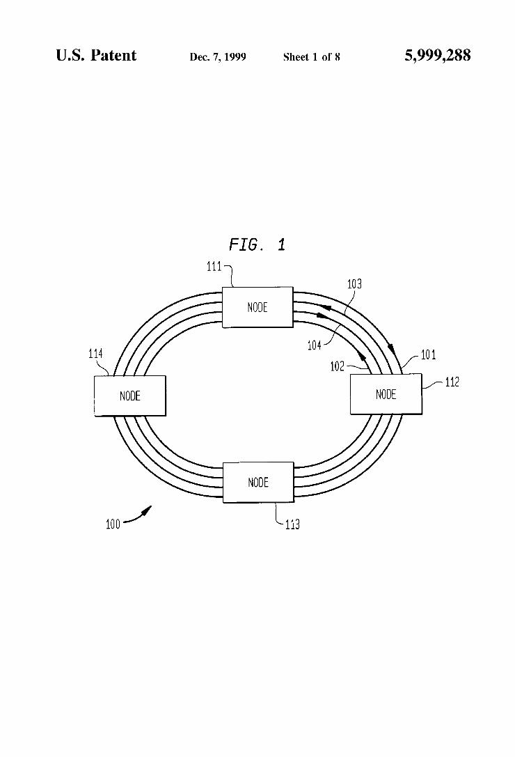
healing WDM ring. Such a ring is a leading candidate architecture for high capacity local exchange carrier net Works because of the survivability capabilities that the ring provides and the fact that its capacity can be shared by all the netWork nodes connected to the ring. The ring netWork of FIG. 1 depicts an example of a
self-healing ring architecture, namely, a so-called 4-?ber WDM shared protection ring 100. TWo of the ?bers are used as “Working” ?bers (carrying the netWork traffic) and the other tWo are used as “protection” ?bers (dark—used only during a failure in order to restore the service). Since there are tWo Working ?bers available and the connections are alWays routed via shortest paths, every Working ?ber carries only half of the optical signal traf?c on the ring. For instance, given a clockWise Working ?ber ring 101, a coun terclockWise Working ?ber ring 102, along With correspond ing protection ?ber rings 103 and 104, the optical signal traffic from netWork node 111 to netWork node 112 can be carried in the clockWise Working ring 101 and, conversely, the optical signal traf?c from netWork node 112 to netWork node 111 can be carried by counterclockWise ring 102. To recover from ?ber cut failures or netWork node failures, each operational node provides a loop-back protection sWitching function so that traf?c on a Working ring can be diverted to a protection ring to bypass the failure. The subject matter of the present invention deals With a
general ring architecture Which is composed of a clockWise Working ring and a counterclockWise Working ring; a self healing ring is but one example of the general principles in accordance With the present invention.
In assigning Wavelengths to carry the optical signals, it is necessary to ensure that optical signals simultaneously shar ing a single ?ber have different Wavelengths; otherWise, a so-called Color Clash (CC) occurs or, expressed equivalently, there Would be in violation of the CC con straint.
In addition, it is also important practically to deploy a minimum number of Wavelengths in implementing the ring netWork. Each additional Wavelength typically requires electro-optical equipment (e.g., an optical netWork card including a laser) to be added in each node, thereby increas ing not only the cost of connection set-up in the netWork but the costs of provisioning and maintenance of the netWork as Well.
In the past, ad hoc procedures have been devised in an attempt to assign Wavelengths to the required connections in the netWork so as to avoid Color Clash violations. As suggested, these procedures are not systematic nor scalable. These methods are not systematic because the techniques rely upon trial-and-error attempts to produce a viable Wave length assignment for a given interconnection con?guration, for a given number of nodes in the ring. These methods are not scalable in the sense that if it is desired to add another node to the netWork With minimal disruption to the inter connections of the already-present nodes, there is no knoWn
5,999,288 3
prior art technique for adding this node in an orderly or systematic Way While ensuring use of the minimum number of Wavelengths, shortest path routing, and avoidance of a Color Clash. In contrast, in accordance With the present invention, the scaling technique for adding tWo nodes results in no disruptions, Whereas the scaling technique for adding one node results in disturbing a very small number of existing connections.
Areference representative of the technological ?eld of the present invention Which discusses the ad hoc technique is the article entitled “MultiWavelength Survivable Ring Net Work Architectures”, authored by A. F. Elrefaie and pub lished in the Proceedings of the International Conference in Communications (ICC), 1993. Whereas this reference does address the issue of determining the minimum number of Wavelengths to avoid violation of the CC constraint (for the case of odd nodes on the ring only), an ad hoc technique for assigning Wavelengths to all connections on the ring is presented, Which is only satisfactory for situations in Which the number of nodes on the ring is an odd number. This reference does not address the case When the number of nodes on the ring is an even number. Moreover, the ad hoc method does not address a procedure for the systematic determination of Wavelength assignment, nor a systematic procedure for assigning Wavelengths When the ring netWork scales.
Thus, a need exists in the art for a systematic procedure to implement a Wavelength assignment in a ring netWork With a minimum number of Wavelengths, for either an even or odd number of nodes, in accordance to shortest path routing and Without a Color Clash. Furthermore, a need exists in the art for a systematic method to assign Wave lengths to the network connections Whenever it is desirable/ necessary to add nodes to the netWork.
SUMMARY OF THE INVENTION
These shortcomings and other limitations and de?ciencies are obviated in accordance With the present invention by a Wavelength assignment and routing approach that is systematic, can handle either an even number or an odd
number of nodes, is scalable, and Which precludes Color Clash violations.
In accordance With the present invention, the point of departure considers the routing and Wavelength assignment problem for a single 4-?ber shared protection self-healing ring, Which Was initially approached from the static point of vieW. The assumptions are that a suf?cient number of Wavelengths are available for full mesh connectivity on the ring, and that each node on the ring communicates With each other on the ring With a single Wavelength. Given these assumptions, one preferred technique (matrix algorithm) calculates the Wavelengths assigned to each connection in advance and, if full mesh connectivity is required, assigns the Wavelengths to all connections as speci?ed by the matrix. Similarly, if partial connectivity is required, When a connection request arrives, the algorithm ?nds the shortest path route and assigns the Wavelength speci?ed in the matrix for this connection. Since enough Wavelengths are available for full mesh connectivity and each connection does not require more than one Wavelength, this matrix-driven tech nique Will alWays Work for both static full mesh connectivity or dynamic (on-the-?y) partial connectivity. Moreover, once connection set-up in the netWork has been established, shortest path routing over the netWork is immediately real iZable.
In accordance With the broad aspect of the present invention, a method is set forth for physically implementing
25
35
45
55
65
4 a Wavelength division multiplexing netWork composed of clockWise and counterclockwise rings and interconnecting nodes via speci?c Wavelengths. The method includes the steps of (1) systematically selecting, based upon a pre scribed mathematical algorithm, a Wavelength assignment for each of the node pair connections, the algorithm being determined to satisfy knoWn grade-of-service constraints for the netWork, such as minimiZing the number of Wavelengths, and scaling the netWork While minimiZing the disruption to the existing connections, and (2) interconnecting each node pair With the corresponding assigned Wavelength.
In accordance With yet another aspect of the present invention, once the connection set-up in the netWork has been established using the prescribed algorithm, routing of traffic over the netWork is effected via shortest path routing.
BRIEF DESCRIPTION OF THE DRAWINGS
The teachings of the present invention can be readily understood by considering the folloWing detailed descrip tion in conjunction With the accompanying draWings, in Which:
FIG. 1 illustrates a conventional four node, bi-directional 4-?ber shared protection self-healing ring architecture hav ing four ?bers (2 Working ?bers in opposite directions and 2 protection ?bers in opposite directions) connecting each adjacent pair of nodes representative of ring technology;
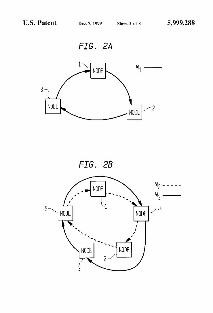
FIG. 2A illustrates Wavelength assignment for a simple netWork With three nodes (clockWise direction only), Whereas FIG. 2B illustrates the additional Wavelength assignment as the number of nodes of FIG. 2A increases from three to ?ve nodes (clockWise direction only);
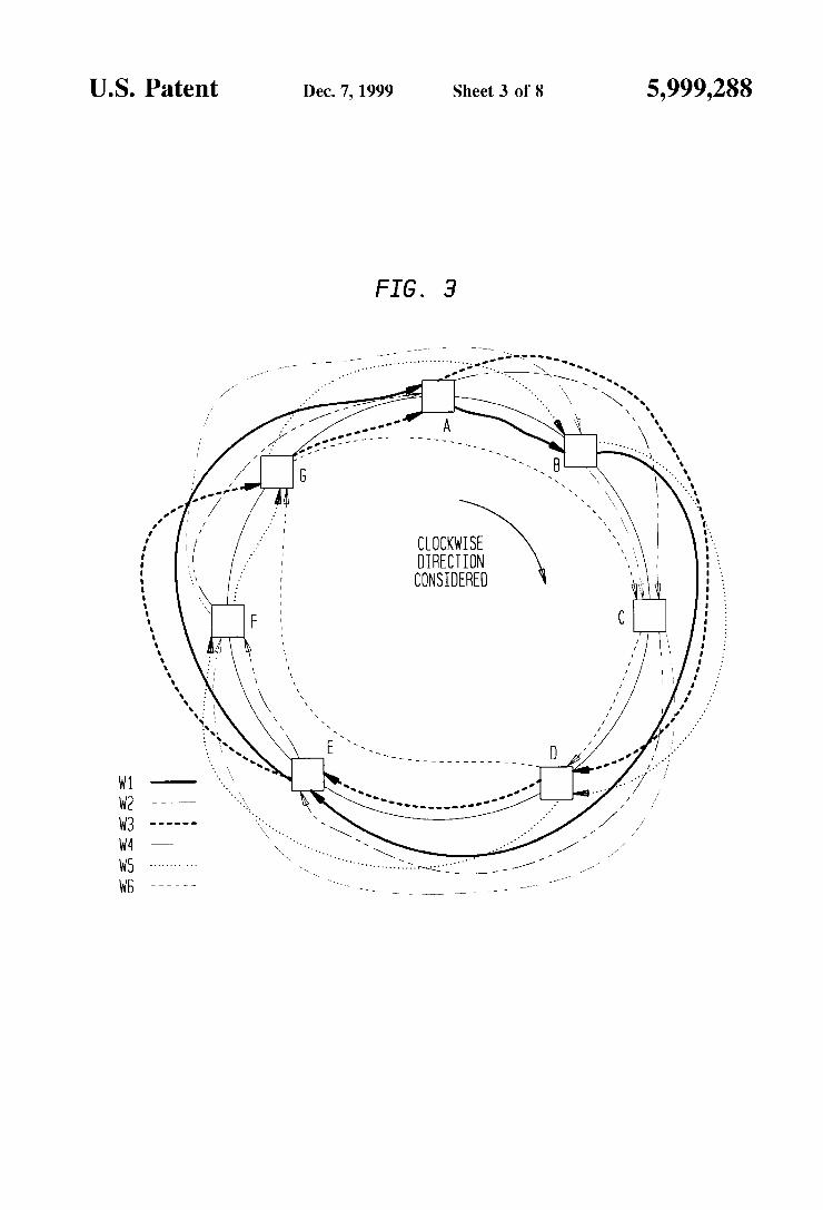
FIG. 3 illustrates the Wavelength assignments (in clock Wise direction only) for a seven node netWork using the matrix assignment algorithm;
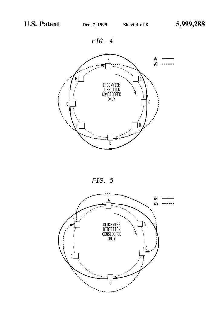
FIG. 4 illustrates the Wavelength assignments for the longest connections for a ring With eight nodes (clockWise direction considered only);
FIG. 5 illustrates the Wavelength assignments for the longest connections for a ring With six nodes (clockWise direction considered only);
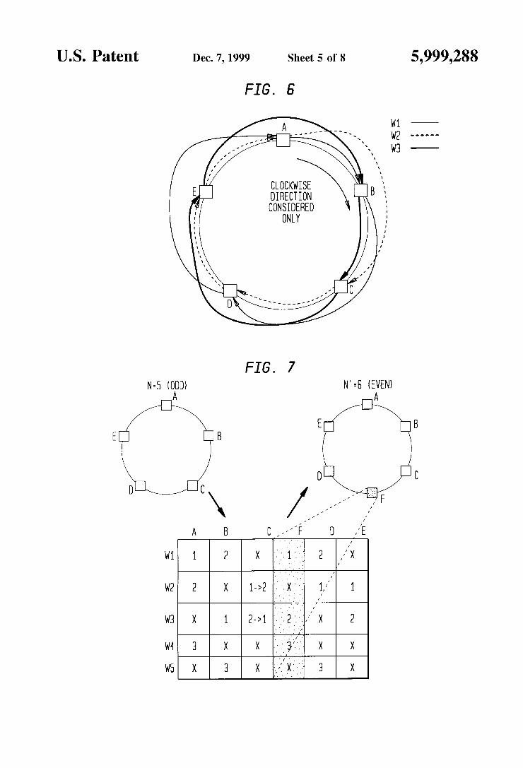
FIG. 6 illustrates the Wavelength assignment for a ring With 5 nodes using the matrix assignment algorithm (clockWise direction considered only);
FIG. 7 illustrates the matrix table When an original netWork having ?ve nodes is scaled to a neW netWork With one added node;
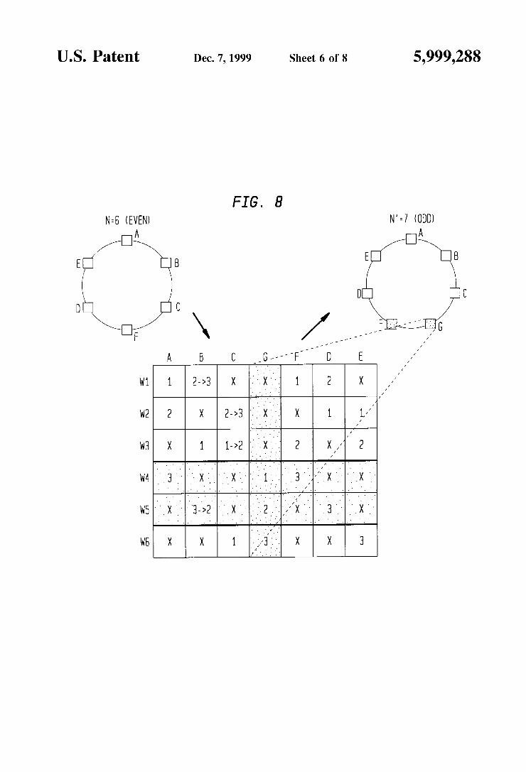
FIG. 8 illustrates the matrix table When an original netWork having six nodes is scaled to a neW netWork With one added node;
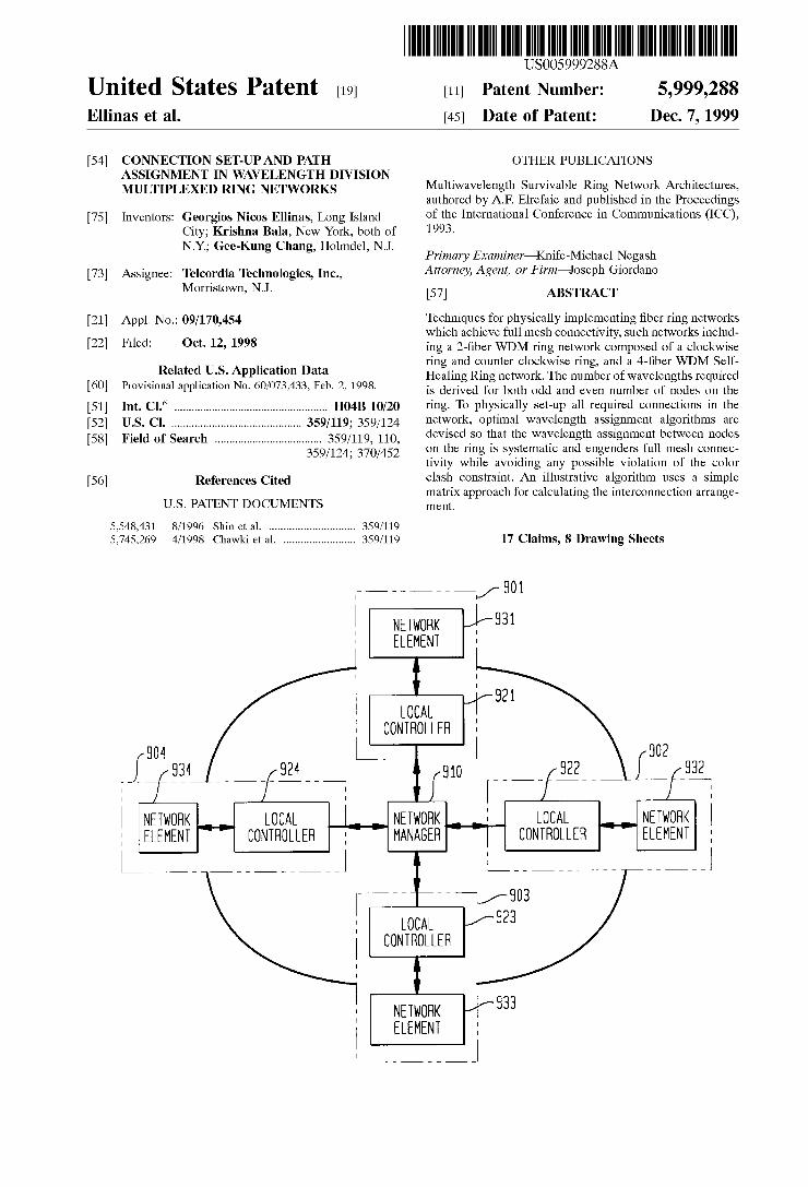
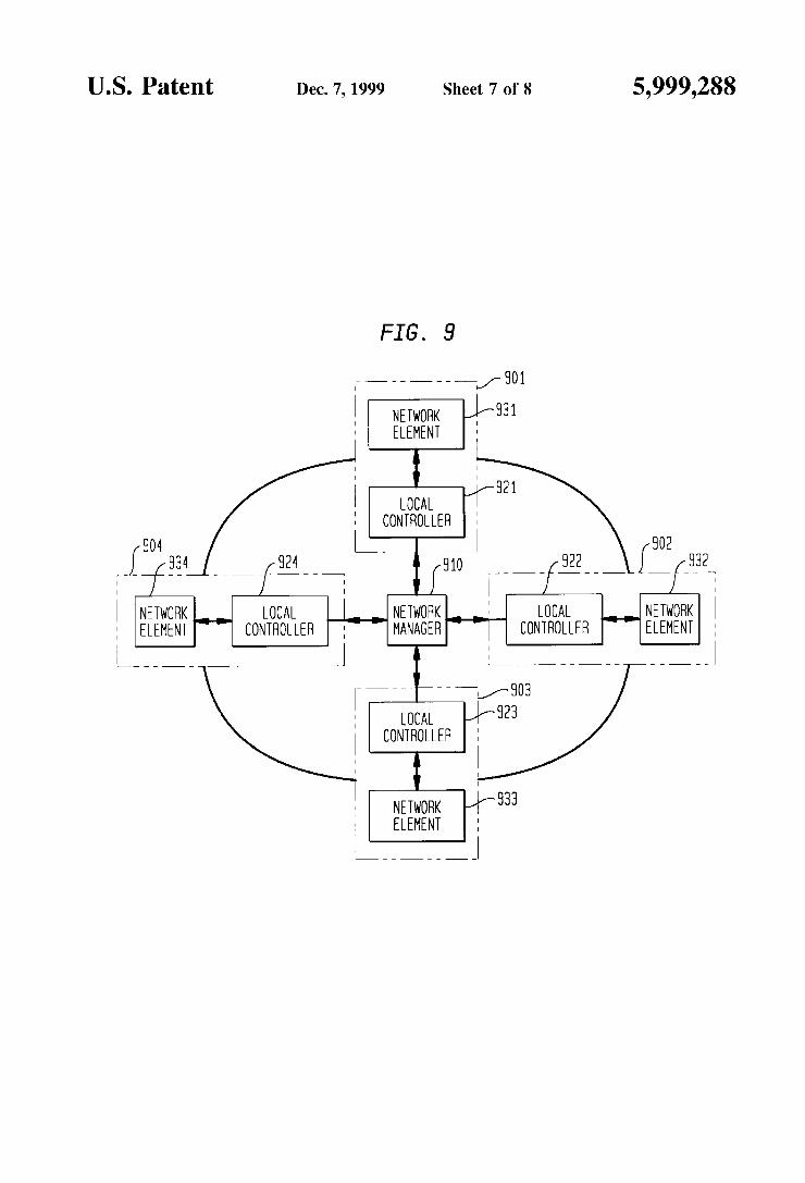
FIG. 9 illustrates the netWork con?guration. Each netWork node comprises of a netWork element and a local controller. A netWork manager is interacting With the local controllers in order to establish the connection set-up and the routing of the traf?c in the ring netWork; and
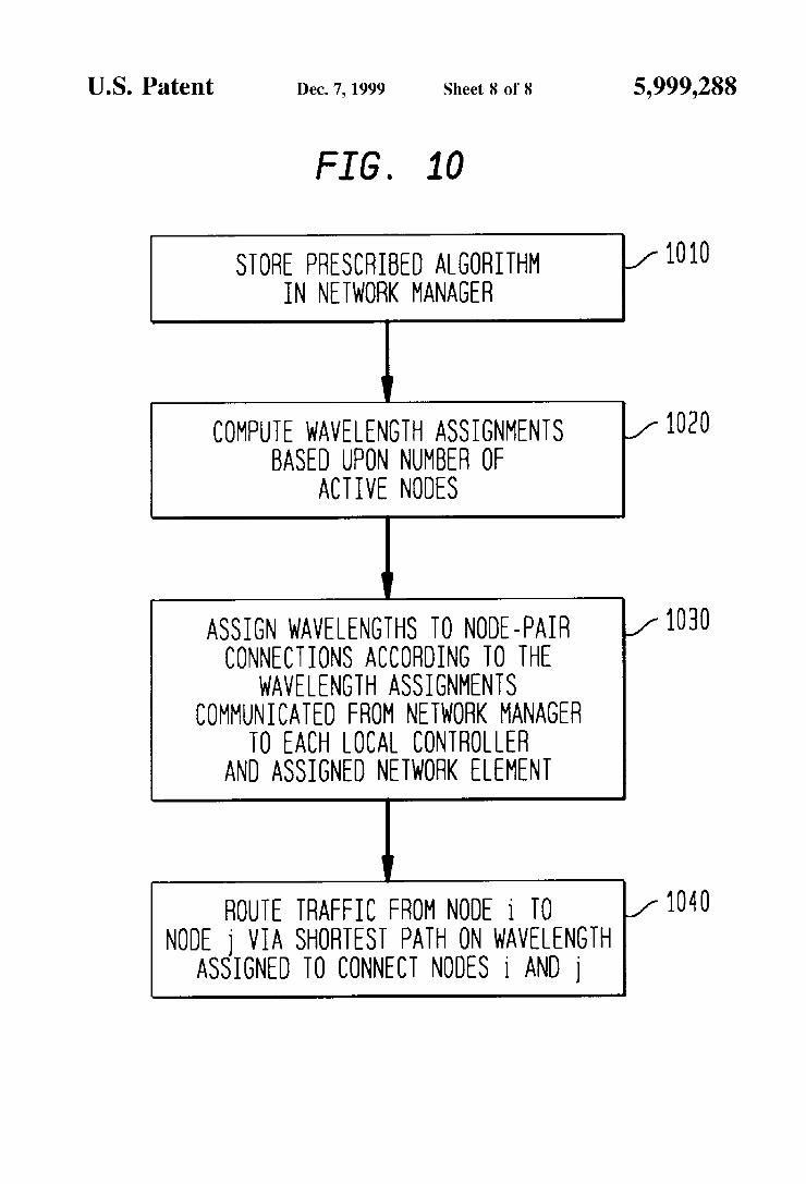
FIG. 10 is a high-level ?oW diagram of the method carried out by the netWork manager, in conjunction With the local controller and netWork element, for both the Wavelength assignment and routing functions in the ring netWork. To facilitate understanding, identical reference numerals
have been used, Where possible, to designate identical elements that are common to the ?gures.
DETAILED DESCRIPTION
After considering the folloWing description, those skilled in the art Will clearly realiZe that the teachings of this
5,999,288 5
invention can be readily utilized in providing Wavelength Division Multiplexing services, including Wavelength assignment, either statically or dynamically, as Well as shortest path routing over the con?gured netWork.
First, the minimum number of Wavelengths required for such a ring, differentiating betWeen the cases of odd and even number of nodes on the ring, is elucidated.
Next, an illustrative embodiment of an optimal Wave length assignment technique, based on a matrix approach, is discussed; this technique assigns the minimum number of Wavelengths required to all connections on the ring so that there is no Color Clash. Again, the cases of odd and even number of nodes on the ring are solved separately. The scalability of the technique is then covered.
Finally, an alternative embodiment of an optimal Wave length assignment scheme, based on a modular approach, Which also ensures no Color Clash violations, is discussed, along With scaling considerations.
Connection Set-up Characteristics
The folloWing characteristics summariZe the manner in Which the Wavelength division multiplexing netWork is optimiZed:
(1) deploys the minimum number of Wavelengths for full mesh connectivity, Without violating the Color Clash constraint, Wherein full-mesh connectivity means that each node in the netWork is directly connected to each of the other nodes;
(2) routing is via the shortest path (if the number of nodes is odd, there is only one shortest path to most distant node; if the number of nodes is even, then there are tWo shortest paths to the most distant node, and one is
selected); (3) one dedicated Wavelength per connection.
The full import of these characteristics Will be covered in detail in the sequel.
First, pedagogically, it is instructive to understand Wave length assignment from an overvieW perspective, as Well as the incremental changes to a given ring as it is scaled, that is, as nodes are added. To this end, reference is made to FIG. 2A Wherein is shoWn the Wavelengths assignments for a ring With N=3 nodes. One Wavelength, namely, W1, suf?ces to interconnect the three nodes (note that only the clockWise direction is shoWn and the other three connections (not shoWn) use the same Wavelength in the other direction (using the second ?ber)). With reference to FIG. 2B, there are shoWn the neW connections as the number of nodes in the netWork increases from N=3 to N=5 nodes. NoW, tWo more Wavelengths, namely W2 and W3, are needed to effect full mesh connectivity. I. Number of Wavelengths Required for Full Mesh Connec tivity
For an N-node ring, each node, i, is connected to all other (N-1) nodes on the ring via shortest path routes. The direction chosen for each connection (clockWise or counter clockWise) is the determining factor for the shortest path route. Since the netWork is symmetric, all the analysis done in one direction can be applied to the other direction as Well. The analysis differentiates betWeen the cases of odd and even number of nodes attached to the ring.
I.1 Odd Number of Nodes on the Ring (N=N0dd) In order to ?nd the minimum number of Wavelengths
required for full mesh connectivity, While observing the Color Clash constraint, a calculation of the maximum num ber of connections that share a single ?ber, in a single direction, is required. This in turn Will equal the minimum
10
15
25
35
45
55
65
6 number of Wavelengths required to complete all connections Without violating the Color Clash constraint. Since the shortest route is alWays chosen, the longest path for inter connecting any tWo nodes equals
Nodd+l 1 [ 2 )
segments of the ring Wherein a segment is noW speci?cally de?ned as a link betWeen tWo adjacent nodes on the ring. Therefore, at most (N0dd+1)/2 nodes Will share a common ?ber. The minimum number of Wavelengths, Wodd, required for full connectivity is thus given by:
12 Even Number of Nodes on the Ring (N=Nevm) In this case, When choosing the shortest route, the longest
path for interconnecting any tWo nodes equals
Neven ( 2 1
segments of the ring. Therefore, at most
NEvm+Z ( 2 1
nodes Will share a common ?ber. A suf?cient number of Wavelengths (i.e., upper bound), W required for full mesh connectivity is thus given by:
(1)
even’
even case requires as many Wavelengths as the “next odd” (N€ven+1) case. While equation (2) assumes that all shortest path connections are allocated in a single direction, a neW expression can be found by taking into consideration the fact that When there are an even number of nodes on the ring, the shortest path for the longest connections can be in either direction. The analysis differentiates betWeen the case Where
The N
[ Neven ] 2
is an even number, i.e., the number of nodes on the ring is divisible by 2 and 4, (called the New; case) and the case Where
[ Neven ] 2
is an odd number, i.e., the number of nodes on the ring is divisible by 2 but not divisible by 4, (called the Nevmo). For these cases, full mesh connectivity can be achieved With a number of Wavelengths given by equations (3) and (4), respectively:
(3)
(4)
It is also readily shoWn that the minimum number of Wavelengths required (Wodd, Wevene and Weveno, respectively) is also the suf?cient number of Wavelengths for full mesh connectivity Without violating the Color Clash constraint.
5,999,288 7
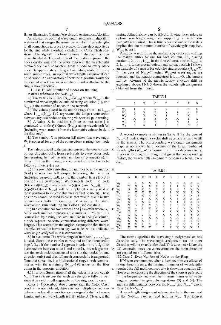
II. An Illustrative Optimal Wavelength Assignment Alorithm An illustrative optimal Wavelength assignment algorithm
is devised that assigns the minimum number of Wavelengths to all connections in order to achieve full mesh connectivity for the ring While avoiding violating the Color Clash con straint. The algorithm is based upon a matrix approach, as noW elucidated. The columns of the matrix represent the nodes on the ring and the roWs represent the Wavelengths required for each connection from a node to every other node. By appropriately ?lling in the matrix, While folloWing some simple rules, an optimal Wavelength assignment can be obtained. An explanation of hoW the algorithm Works for the case of an odd and even number of nodes attached to the ring is noW presented.
II.1 Case 1: Odd Number of Nodes on the Ring Matrix De?nitions for N=N0dd: 1.) The matrix is of siZe (NoddxWodd) Where Wodd is the
number of Wavelengths calculated using equation (1), and Nodd is the number of nodes in the netWork.
2.) The values placed in the matrix range from 1 to Lmwc, Where Lmwc=(N0dd—1)/2 represents the longest connection betWeen any tWo nodes on the ring via shortest path routing.
3.) A value K in position (i,j) states that node j is connected to node (j+K)mod (Nodd) using Wavelength W, (including Wrap-around (from the last matrix column back to the ?rst one)).
4.) The symbol X in position (i,j) states that Wavelength Wi is not used for any of the connections starting from node J.
The values placed in the matrix represent the connections, on one direction only, from each node to every other node (representing half of the total number of connections). In order to ?ll in the matrix, a speci?c set of rules has to be folloWed; these rules are:
1.) In a roW: After inserting the number K in the matrix, (K—1) spaces are left empty folloWing that number (including Wrap-around), i.e., if the number K is placed at position (i,j) (Wavelength Wi connects node j to node (K+j)mod(NOdd)), then positions (i,((j+1)mod N0dd)), . . . ,
(i,(j+(K-1))mod Nodd) Will be empty (X’s are placed at those positions to indicate that they cannot be used)). These positions cannot be used because that Would result in tWo connections With intersecting paths using the same Wavelength, thus violating the Color Clash constraint.
2.) In a column: No tWo entries i andj can exist Where i=j. Since each number represents the number of “hops” in a connection, by having the same number in a single column, a node repeats the same connection using different Wave lengths. This contradicts the original assumption that there is a single connection betWeen any tWo nodes With a dedicated Wavelength assigned to that connection.
3.) In a column: The Whole range of numbers 1, . . . , Lmwc
is used. Since these entries correspond to the “connection hops”, (i.e., if the number 2 appears in column 1, it signi?es a connection betWeen node 1 and node 3), this rule guaran tees that each node is connected With all other nodes (on one direction only) and thus full mesh connectivity is supported. Note that since this is a bi-directional ring, a node commu nicates With the remaining (NOdd—1)/2 nodes on the ?ber going in the opposite direction.
4.) In a roW: Summation of all the values in a roW equals Nodd. This rule ensures that each Wavelength is fully utiliZed since it is used on all segments on the ring exactly once.
Rules 1—4 described above ensure that the Color Clash condition is not violated; there exist no multiple connections betWeen nodes; all connections are assigned a distinct Wave length; and each Wavelength is fully utiliZed. Clearly, if the
10
15
25
35
45
55
65
8 matrix de?ned above can be ?lled folloWing these rules, an optimal Wavelength assignment supporting full mesh con nectivity is obtained. This is true, since the siZe of the matrix implies that the minimum number of Wavelengths required, Wodd is used. A simple Way to ?ll in the matrix is by cyclically shifting
the matrix entries by one for each column, i.e., placing entries 1, 2, . . . , L in the ?rst column, entries L 1, max max’
2, L max-1 in the second column and so on. TABLE I shoWs an example of a matrix for odd siZe ring netWorks (N0dd=7). In the case of N0dd=7 nodes, W0dd=6 Wavelengths are required and the longest connection is Lmax=3. The entries for the columns of the matrix folloW a cyclic shift as explained above. FIG. 3 shoWs the Wavelength assignment obtained from the matrix.
TABLE I
A B c D E F G
W1 1 3 x x 3 x x W2 2 x 2 x 1 2 x W3 3 x x 1 2 x 1 W4 x 1 3 x x 3 x W5 x 2 x 2 x 1 2 W6 x x 1 3 x x 3
A second example is shoWn in Table II for the case of N0dd=11 nodes. Again a cyclic shift approach is used to ?ll in the matrix. The corresponding Wavelength assignment graph is not shoWn here because of the large number of Wavelengths (WOW-15) required for full mesh connectivity. It is easy to recogniZe though that given the corresponding matrix, the Wavelength assignment becomes a trivial exer c1se.
TABLE II
A B c D E F G H I J K
W1 1 5 x x x x 5 x x x x W2 2 x 4 x x x 1 4 x x x W3 3 x x 3 x x 2 x 3 x x W4 4 x x x 2 x 3 x x 2 x W5 5 x x x x 1 4 x x x 1 W6 x 1 5 x x x x 5 x x x W7 x 2 x 4 x x x 1 4 x x W8 x 3 x x 3 x x 2 x 3 x W9 x 4 x x x 2 x 3 x x 2 W10 x x 1 5 x x x x 5 x x W11 x x 2 x 4 x x x 1 4 x W12 x x 3 x x 3 x x 2 x 3 W13 x x x 1 5 x x x x 5 x W14 x x x 2 x 4 x x x 1 4 W15 x x x x 1 5 x x x x 5
The matrix speci?es the Wavelength assignment on one direction only. The Wavelength assignment on the other direction Will be exactly identical. This does not violate the CC constraint since the connections on the other direction are carried on a different ?ber.
H2 Case 2: Even Number of Nodes on the Ring If N is an even number, When all connections are allocated
in one direction only, the minimum number of Wavelengths
required for full mesh connectivity is shoWn in equation HoWever, by choosing the direction of the shortest path route
for the longest connections, the minimum number of Wave lengths required is given by equations (3) and The analysis differentiates betWeen the New; and Neveno cases: Case 2a: N=Nevme AWavelength assignment scheme similar to the one used
in the N=N0dd case is used here as Well. The longest
5,999,288 9
connections are allocated ?rst, using a neW allocation scheme presented beloW, and Name/4 Wavelengths are assigned to these connections. The rest of the connections are allocated using a modi?ed matrix approach:
(i) For all the longest connections, a neW Wavelength assignment scheme is de?ned that assigns Wavelength Wi for connections (j,k) and (k,j), on one direction as Well as connections (j+1),(k+1) and (k+1),(j+1) on the other direction, Wavelength W041) for connections (j+2),(k+2) and (k+2),(j+2), on one direction, and connections (j+3),(k+3) and ((k+3),(j+3) on the other direction and so on. In general, the Wavelength assignment algorithm alternates directions for alternating nodes on the ring and assigns to both pairs of connections (a connection pair is a pair (i,j), (j,i)) the same Wavelength.
Because of the Wavelength reuse, only as many Wave lengths as half the number of connections (Name/4) are needed to color all the longest connections Without violating the CC constraint. The total number of Wavelengths required to color all connections Will then be equal to Wlongme in addition to the number of Wavelengths required to color the remaining connections (W,emaine=(Nevm€—1)2/8). Thus’ Wevene=Wl0ngeste+Wremaine=(Nevene)2/8'
(ii) The rest of the connections are assigned Wavelengths using the folloWing modi?ed matrix approach:
Matrix De?nitions for N=Nevene 1. The matrix is of siZe (WprevoxNevme) Where Wprevo is
the number of Wavelengths for the previous odd case, calculated using equation (1), and Nevme is the number of nodes on the ring.
2. The values placed in the matrix range from 1 to (Lmax—1), Where Lmwc represents the longest connection betWeen any tWo nodes on the ring. The number Lmwc—1 represents the longest connection betWeen any tWo nodes in the “previous odd” (Np,€v0=Nevene—1) case.
3. Avalue K in position (i,j) states that node j is connected to node (j+K)mod (Nevme) using Wavelength Wi.
4. The symbol X in position (i,j) states that Wavelength Wi is not used for any of the connections starting from node j. The values placed in the matrix represent all but the longest connections, on one direction only, from each node to every other node. The same matrix rules as in Case 1 apply here as Well. Clearly, ?lling matrix (WprevoxNevme) folloWing these rules, together With the neW Wavelength assignment scheme for the longest connections, corresponds to an optimal Wavelength assignment supporting full mesh con nectivity. The neW matrix is noW ?lled as folloWs:
Step 1: The previous odd matrix is ?lled using the cyclic shift method.
Step 2: A neW column is added to the matrix at any arbitrary location.
Step 3: For each roW, starting from the neW column, the algorithm traverses the roW toWards the left (including Wrap-around), until it encounters the ?rst number entry (other than an
The neW column is noW ?lled using tWo simple rules: Rule 1: If the number entry encountered, K, is less than
the longest connection entry for the previous odd case Lmwcprevwdd), place an X at the neW column and incre ment K by 1.
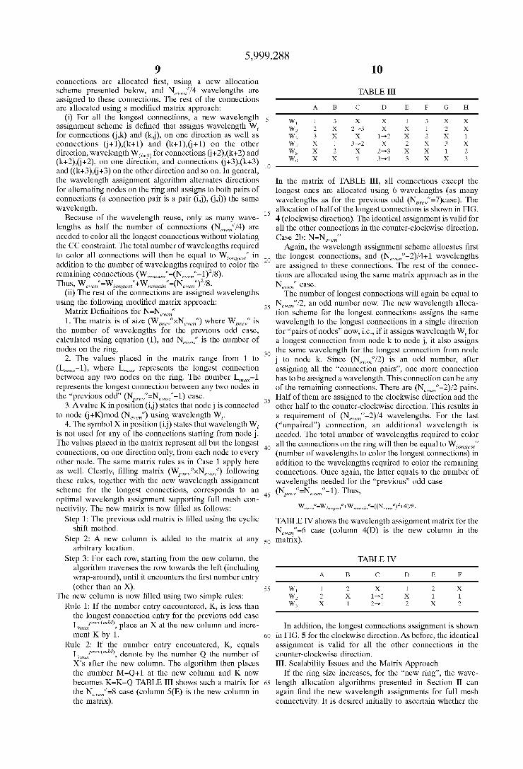
Rule 2: If the number entry encountered, K, equals Lmwcprevwdd), denote by the number Q the number of X’s after the neW column. The algorithm then places the number M=Q+1 at the neW column and K noW becomes K=K—Q TABLE III shoWs such a matrix for the N €=8 case (column 5(E) is the neW column in even
the matrix).
10
15
25
35
45
55
65
TABLE III
A B c D E F G H
W1 1 3 x x 1 3 x x W2 2 x 2—>3 x x 1 2 x W3 3 x x 1—>2 x 2 x 1 W4 x 1 3—>2 x 2 x 3 x W5 x 2 x 2—>3 x x 1 2 W6 x x 1 3—>1 3 x x 3
In the matrix of TABLE III, all connections except the longest ones are allocated using 6 Wavelengths (as many Wavelengths as for the previous odd (Np,ev0=7)case). The allocation of half of the longest connections is shoWn in FIG. 4 (clockWise direction). The identical assignment is valid for all the other connections in the counter-clockwise direction. Case 2b: N=Nevm0
Again, the Wavelength assignment scheme allocates ?rst the longest connections, and (NevmO—2)/4+1 Wavelengths are assigned to these connections. The rest of the connec tions are allocated using the same matrix approach as in the New; case. The number of longest connections Will again be equal to
Name/2, an odd number noW. The neW Wavelength alloca tion scheme for the longest connections assigns the same Wavelength to the longest connections in a single direction for “pairs of nodes” noW, i.e., if it assigns Wavelength Wi for a longest connection from node k to node j, it also assigns the same Wavelength for the longest connection from node j to node k. Since (Name/2) is an odd number, after assigning all the “connection pairs”, one more connection has to be assigned a Wavelength. This connection can be any of the remaining connections. There are (Neven0—2)/2 pairs. Half of them are assigned to the clockWise direction and the other half to the counter-clockwise direction. This results in a requirement of (Neven0—2)/4 Wavelengths. For the last (“unpaired”) connection, an additional Wavelength is needed. The total number of Wavelengths required to color all the connections on the ring Will then be equal to Wlongesto (number of Wavelengths to color the longest connections) in addition to the Wavelengths required to color the remaining connections. Once again, the latter equals to the number of Wavelengths needed for the “previous” odd case (N 0=N 0-1). Thus, prev even
TABLE IV shoWs the Wavelength assignment matrix for the N 0=6 case (column 4(D) is the neW column in the even
matrix).
TABLE IV
A B c D E
W1 1 2 x 1 2 x W2 2 x 1—>2 x 1 1 W3 x 1 2—>1 2 x 2
In addition, the longest connections assignment is shoWn in FIG. 5 for the clockWise direction. As before, the identical assignment is valid for all the other connections in the counter-clockwise direction. III. Scalability Issues and the Matrix Approach
If the ring siZe increases, for the “neW ring”, the Wave length allocation algorithms presented in Section II can again ?nd the neW Wavelength assignments for full mesh connectivity. It is desired initially to ascertain Whether the
5,999,288 11
size of the ring can be increased without having to reassign wavelengths to the already existing connections (the so-called recursive approach). There is a two-fold approach to the problem: (1) When the new nodes are added to speci?ed locations on the ring, the wavelength assignment of the already existing connections cannot, in most cases, be maintained. A new matrix must be calculated, and corre sponding wavelengths must then be assigned. (2) When the new nodes can be added at any position on the ring, however, the wavelength assignment of already existing connections can always be maintained provided the new nodes are added at appropriate locations. This is a desirable case since nodes already on the ring are not affected by the addition of the new nodes, and the new nodes are integrated seamlessly into the ring. The latter case is the one now presented.
Moreover, the interest initially focuses on the case wherein the number of nodes on the ring is incremented by 2, i.e., scaling the network from Nodd to Noddnew or from N to N
even
Scaling by +2 Case 1. Nodd =N0dd+2
The same 'f?atrix approach is used with the new matrix having the following characteristics:
1. The matrix is now of siZe Wodd ><N0dd where Wodd
is the number of wavelengths (calcu'lzated usimrivg equation for N=N0dd and Nodd =N0dd+2 is the new number of
nodes in themhetwork. new
2. The values placed in the matrix range from 1 to Lmax, where Lmwc represents the longest connection between any two nodes that exist on the “new” ring. This number equals
Lmax=(N0ddmw—1)/2. The matrix is now ?lled in as follows:
(i) The matrix is expanded from WoddxNodd to Wodd >< Nodd . The number of columns is increased by 2 and "the number of rows is increased by (Nodd —1)/2 to correspond to Wodd . The two new columns are “added” at positions k (k beirfgw any column number) (new column A) and (k+Lm?_x ) (new column B) where Lmax is the longest connectigh for the previous ring (N=N0dd
(ii) For rows 1, . . . , Wodd and all but the new columns,
place the values calculated for previous matrix WoddxNodd. (iii) For rows 1, . . . , Wodd, place the value X in the new
columns. By adding the X’s at those positions, it is guar anteed that the previous connections maintain their previous wavelength assignments.
(iv) For rows 1, . . . , Wodd, backtracking from the ?rst
“new” column, the ?rst value encountered that is not an X is incremented by 1. The same process repeats for the second “new” column. Note that while backtracking, it is possible to loop-around the matrix. By incrementing those values by 1, the connection (hop) number is increased to correspond to the new connection numbers (due to the insertion of the new nodes). Because of step (ii), there is never a new value greater than the allowable number of hops for the connec tions in the new ring.
(v) Steps (i), . . . , (iv) ?ll in the ?rst Wodd rows of the matrix. The rest of the rows are ?lled as follows:
(a) New columns A and B (rows WOdd+1—W0dd ) are ?lled with values 1,2,3, . . . , Lmax in sequencenfw
(b) For all other columns (except new columns A and B), rows WOdd+1—W0dd are ?lled with the missing hop number (hop numbenrfwnot used in rows 1, . . . , Wodd) for each column.
It is clear because the matrix is ?lled using the rules described above, again optimal wavelength assignment
15
25
35
45
55
65
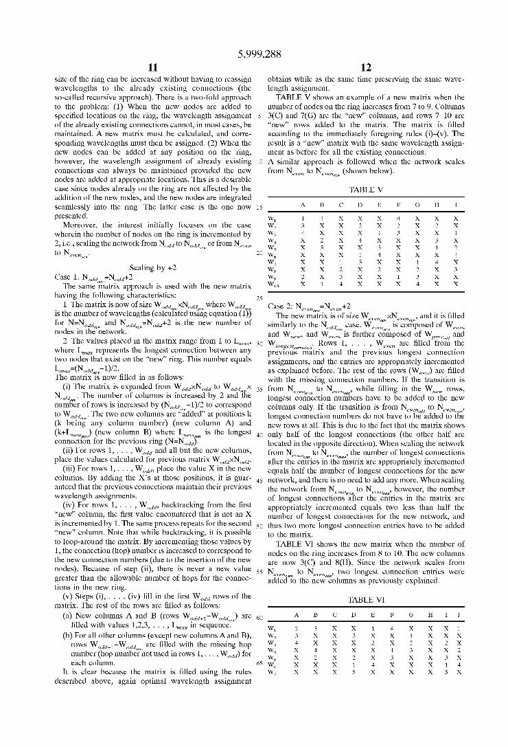
12 obtains while as the same time preserving the same wave length assignment. TABLE V shows an example of a new matrix when the
number of nodes on the ring increases from 7 to 9. Columns 3(C) and 7(G) are the “new” columns, and rows 7—10 are “new” rows added to the matrix. The matrix is ?lled according to the immediately foregoing rules (i)—(v). The result is a “new” matrix with the same wavelength assign ment as before for all the existing connections. A similar approach is followed when the network scales from New” to Nevmmw (shown below).
TABLE V
A B C D E F G H I
W1 1 4 x x x 4 x x x W2 3 x x 2 x 2 x 2 x W3 4 x x x 1 3 x x 1 W4 x 2 x 4 x x x 3 x W5 x 3 x x 3 x x 1 2 W6 x x x 1 4 x x x 4 W7 x x 1 3 x x 1 4 x W8 x x 2 x 2 x 2 x 3 W9 2 x 3 x x 1 3 x x W1D x 1 4 x x x 4 x x
Case 2: New” =Nevm+2 . The new matrix is of siZe WevmmwxNevmmw, and it is ?lled
similarly to the Nodd case. Weven is composed of WW6” and Wnew, and Weven is further composed of Wprev and Wlongestmmmion. Rows 1, . . . , Weven are ?lled from the previous matrix and the previous longest connection assignments, and the entries are appropriately incremented as explained before. The rest of the rows (WMW) are ?lled with the missing connection numbers. If the transition is from Nevmm to Nevenodd, while ?lling in the Wnew rows, longest connection numbers have to be added to the new columns only. If the transition is from Nevenodd to N , longest connection numbers do not have to be added to the new rows at all. This is due to the fact that the matrix shows only half of the longest connections (the other half are located in the opposite direction). When scaling the network from Nevenodd to Nevenm, the number of longest connections after the entries in the matrix are appropriately incremented equals half the number of longest connections for the new network, and there is no need to add any more. When scaling the network from Nevmm to New” d, however, the number of longest connections after the entries in the matrix are appropriately incremented equals two less than half the number of longest connections for the new network, and thus two more longest connection entries have to be added to the matrix. TABLE VI shows the new matrix when the number of
nodes on the ring increases from 8 to 10. The new columns are now 3(C) and Since the network scales from Nevmm o Nevenodd, two longest connection entries were added to the new columns as previously explained.
TABLE VI
A B c D E F G H I J
W1 1 3 x x 1 4 x x x 1 W2 3 x x 3 x x 4 x x x W3 4 x x x 2 x 2 x 2 x W4 x 4 x x x 1 3 x x 2 W5 x 2 x 2 x 3 x x 3 x W6 x x x 1 4 x x x 1 4 W7 x x x 5 x x x x 5 x
5,999,288
TABLE VI-continued TABLE VIII
A B c D E F G H I J A B c F D E
W8 5 X X X X 5 X X X X 5 W1 1 2 X 1 2 X W9 X X 1 4 X X X 1 4 X W2 2 X 1 —>2 X 1 1 W10 X X 2 X 3 X X 2 X 3 W3 X 1 2—>1 2 X 2 W11 2 X 3 X X 2 X 3 X X W4 3 X X 3 X X W12 X 1 4 X X X 1 4 X X W5 X 3 X X 3 X W13 X X 5 X X X X 5 X X
10
Scaling by +1
This subsection sets forth the more difficult case of adding a single node at a time at any location in the ring. When the siZe of the ring increases by one, the matriX approach may be used to scale the network While reassigning Wavelengths to only a small number of the already-eXisting connections. The analysis differentiates betWeen scaling rings With odd and even number of nodes. For both cases, the matriX scales from {WxN} to {W‘><(N+1)}. The manner in Which the matriX is ?lled is as folloWs.
Case 1: N‘=N+1(N=odd number) This neW method scales a matriX With an odd number of
nodes to a matriX With an even number of nodes While adding the neW node at any location on the ring.
The matriX is eXpanded from {WXN} to {W‘XN‘} Where W=(N2—1)/8. The number of columns is increased 1 and the number of roWs is increased to correspond to the neW number of Wavelengths required, W‘(W‘=(N‘2)/8 or W‘= [(N‘2+4)/8]). For each roW, from the neW column, the algorithm traverses the roW toWards the left (including Wrap-around) until it encounters the ?rst entry (other than an
The ?rst W roWs of the neW column are then ?lled folloWing rules 1 and 2 beloW. The rest of the roWs are ?lled With the longest connection entries using a simple algorithm that places entry L at location (i,j) if entry L is not max max
used in column j, and location (i,j) is empty (no X entry).
Rule 1: If the number entry encountered, K, is less than the longest connection entry for the previous odd case Lmwcprevwdd), place an X at the neW column and incre ment K by 1.
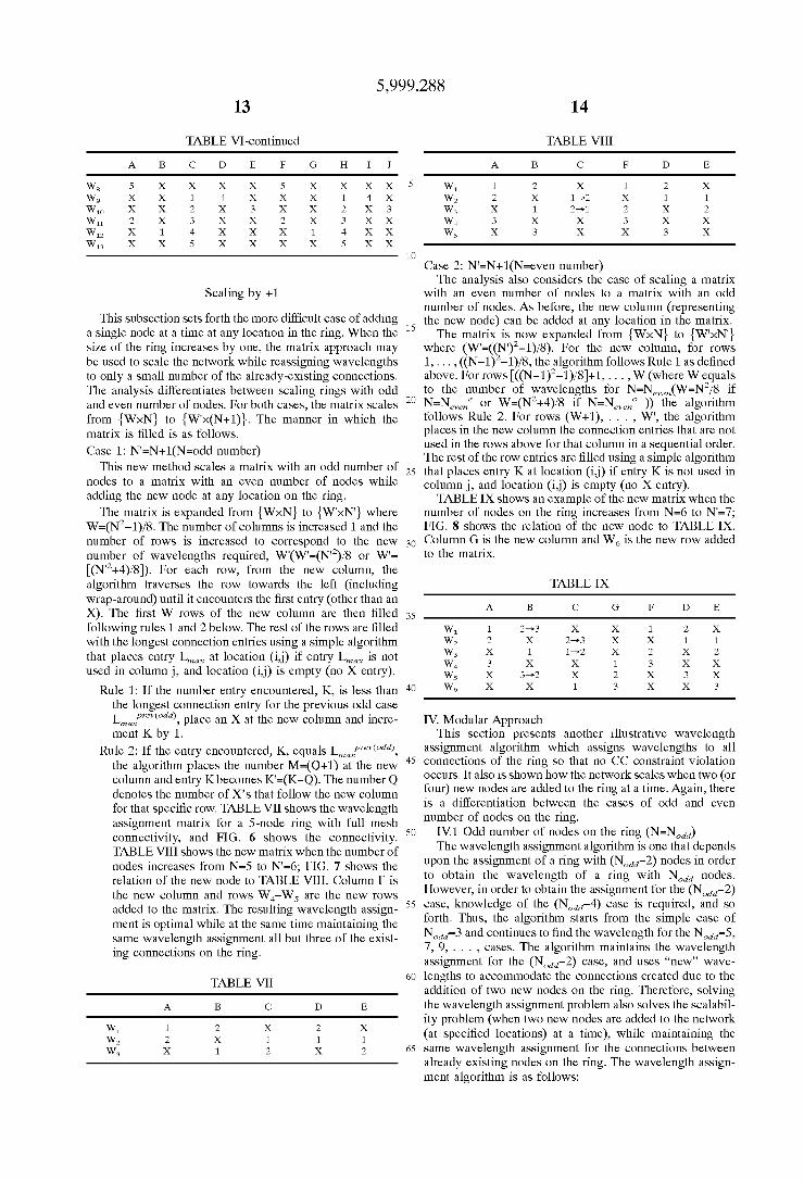
Rule 2: If the entry encountered, K, equals Lmwcprevwdd), the algorithm places the number M=(Q+1) at the neW column and entry Kbecomes K‘=(K—Q). The number Q denotes the number of X’s that folloW the neW column for that speci?c roW. TABLE VII shoWs the Wavelength assignment matriX for a 5-node ring With full mesh connectivity, and FIG. 6 shoWs the connectivity. TABLE VIII shoWs the neW matriX When the number of nodes increases from N=5 to N‘=6; FIG. 7 shoWs the relation of the neW node to TABLE VIII. Column F is the neW column and roWs W4—W5 are the neW roWs added to the matriX. The resulting Wavelength assign ment is optimal While at the same time maintaining the same Wavelength assignment all but three of the eXist ing connections on the ring.
TABLE VII
A B c D E
W1 1 2 X 2 X W2 2 X 1 1 1 W3 X 1 2 X 2
15
25
35
45
55
65
Case 2: N‘=N+1(N=even number) The analysis also considers the case of scaling a matriX
With an even number of nodes to a matriX With an odd number of nodes. As before, the neW column (representing the neW node) can be added at any location in the matriX. The matriX is noW eXpanded from {WXN} to {W‘XN‘}
Where (W‘=( N‘)2—1)/8). For the neW column, for roWs 1, . . . , ((N-1) —1)/8, the algorithm folloWs Rule 1 as de?ned above. For roWs [((N—1)2—1)/8]+1, . . . , W (Where W equals to the number of Wavelengths for N=Nevm(W=N2/8 if N=Nevene or W=(N2+4)/8 if N=Nevmo the algorithm folloWs Rule 2. For roWs (W+1), . . . , W‘, the algorithm places in the neW column the connection entries that are not used in the roWs above for that column in a sequential order. The rest of the roW entries are ?lled using a simple algorithm that places entry K at location (i,j) if entry K is not used in column j, and location (i,j) is empty (no X entry). TABLE IX shoWs an eXample of the neW matriX When the
number of nodes on the ring increases from N=6 to N‘=7; FIG. 8 shoWs the relation of the neW node to TABLE IX. Column G is the neW column and W6 is the neW roW added to the matriX.
TABLE IX
A B c G D E
W1 1 2—>3 X X 1 2 X W2 2 X 2—>3 X X 1 1 W3 X 1 1—>2 X 2 X 2 W4 3 X X 1 3 X X W5 X 3—>2 X 2 X 3 X W6 X X 1 3 X X 3
IV. Modular Approach This section presents another illustrative Wavelength
assignment algorithm Which assigns Wavelengths to all connections of the ring so that no CC constraint violation occurs. It also is shoWn hoW the netWork scales When tWo (or four) neW nodes are added to the ring at a time. Again, there is a differentiation betWeen the cases of odd and even number of nodes on the ring.
IV.1 Odd number of nodes on the ring (N=N0dd) The Wavelength assignment algorithm is one that depends
upon the assignment of a ring With (Nodal-2) nodes in order to obtain the Wavelength of a ring With Nodd nodes. HoWever, in order to obtain the assignment for the (Nodal-2) case, knoWledge of the (Nomi-4) case is required, and so forth. Thus, the algorithm starts from the simple case of N0dd=3 and continues to ?nd the Wavelength for the N0dd=5, 7, 9, . . . , cases. The algorithm maintains the Wavelength
assignment for the (Nomi-2) case, and uses “new” Wave lengths to accommodate the connections created due to the addition of tWo neW nodes on the ring. Therefore, solving the Wavelength assignment problem also solves the scalabil ity problem (When tWo neW nodes are added to the netWork (at speci?ed locations) at a time), While maintaining the same Wavelength assignment for the connections betWeen already eXisting nodes on the ring. The Wavelength assign ment algorithm is as folloWs:
5,999,288 15
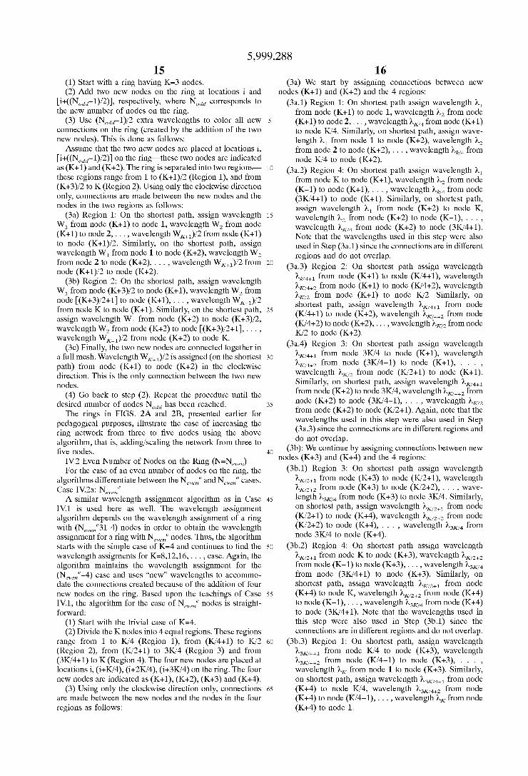
(1) Start With a ring having K=3 nodes. (2) Add tWo neW nodes on the ring at locations i and
[i+((NOdd—1)/2)], respectively, Where Nodd corresponds to the neW number of nodes on the ring.
(3) Use (NOdd—1)/2 extra Wavelengths to color all neW connections on the ring (created by the addition of the tWo neW nodes). This is done as folloWs: Assume that the tWo neW nodes are placed at locations i,
[i+((NOdd—1)/2)] on the ring—these tWo nodes are indicated as (K+1) and (K+2). The ring is separated into tWo regions— these regions range from 1 to (K+1)/2 (Region 1), and from (K+3)/2 to K (Region 2). Using only the clockWise direction only, connections are made betWeen the neW nodes and the nodes in the tWo regions as folloWs:
(3a) Region 1: On the shortest path, assign Wavelength W1 from node (K+1) to node 1, Wavelength W2 from node (K+1) to node 2, . . . , Wavelength WK+1)/2 from node (K+1) to node (K+1)/2. Similarly, on the shortest path, assign Wavelength W1 from node 1 to node (K+2), Wavelength W2 from node 2 to node (K+2), . . . , Wavelength WK+1)/2 from
node (K+1)/2 to node (K+2). (3b) Region 2: On the shortest path, assign Wavelength
W1 from node (K+3)/2 to node (K+1), Wavelength W2 from node [(K+3)/2+1] to node (K+1), . . . , Wavelength WK_1)/2 from node K to node (K+1). Similarly, on the shortest path, assign Wavelength W1 from node (K+2) to node (K+3)/2, Wavelength W2 from node (K+2) to node [(K+3)/2+1], . . . , Wavelength WK_1)/2 from node (K+2) to node K.
(3c) Finally, the tWo neW nodes are connected together in a full mesh. Wavelength WK+1)/ 2 is assigned (on the shortest path) from node (K+1) to node (K+2) in the clockWise direction. This is the only connection betWeen the tWo neW nodes.
(4) Go back to step Repeat the procedure until the desired number of nodes Nodd has been reached.
The rings in FIGS. 2A and 2B, presented earlier for pedagogical purposes, illustrate the case of increasing the ring netWork from three to ?ve nodes using the above algorithm, that is, adding/scaling the netWork from three to ?ve nodes.
IV.2 Even Number of Nodes on the Ring (N=Nevm) For the case of an even number of nodes on the ring, the
algorithms differentiate betWeen the New; and Neveno cases. Case IV.2a: New; A similar Wavelength assignment algorithm as in Case
IV.1 is used here as Well. The Wavelength assignment algorithm depends on the Wavelength assignment of a ring With (Nevene31 4) nodes in order to obtain the Wavelength assignment for a ring With New; nodes. Thus, the algorithm starts With the simple case of K=4 and continues to ?nd the Wavelength assigrnents for K=8,12,16, . . . , case. Again, the
algorithm maintains the Wavelength assignment for the (Name-4) case and uses “new” Wavelengths to accommo date the connections created because of the addition of four neW nodes on the ring. Based upon the teachings of Case IV.1, the algorithm for the case of N 6 nodes is straight forWard:
(1) Start With the trivial case of K=4. (2) Divide the K nodes into 4 equal regions. These regions
range from 1 to K/4 (Region 1), from (K/4+1) to K/2 (Region 2), from (K/2+1) to 3K/4 (Region 3) and from (3K/4+1) to K (Region 4). The four neW nodes are placed at locations i, (i+K/4), (i+2K/4), (i+3K/4) on the ring. The four neW nodes are indicated as (K+1), (K+2), (K+3) and (K+4).
(3) Using only the clockWise direction only, connections are made betWeen the neW nodes and the nodes in the four regions as folloWs:
even
10
15
25
35
45
55
a O
65
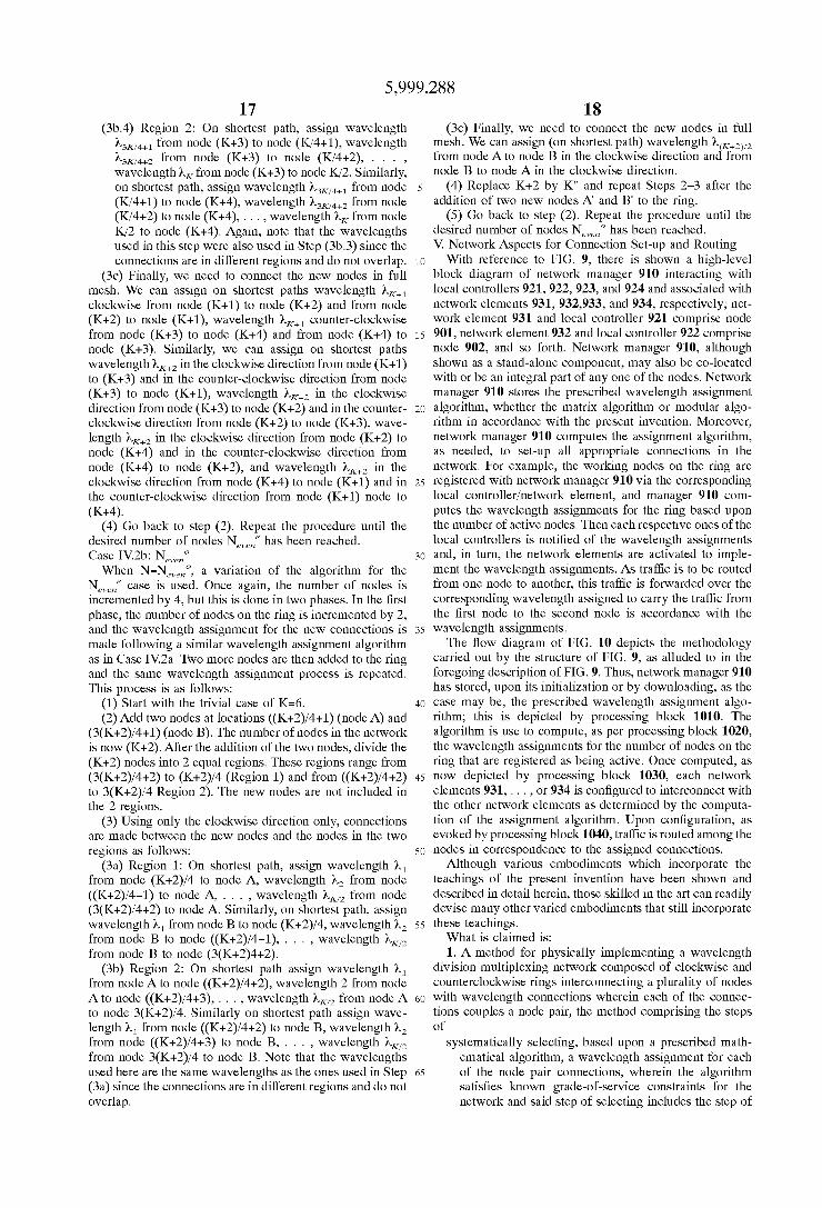
16 (3a) We start by assigning connections betWeen neW
nodes (K+1) and (K+2) and the 4 regions: (3a.1) Region 1: On shortest path assign Wavelength M
from node (K+1) to node 1, wavelength )»2 from node (K+1) to node 2, . . . , Wavelength )tK/4 from node (K+1) to node K/4. Similarly, on shortest path, assign Wave length M from node 1 to node (K+2), wavelength )»2 from node 2 to node (K+2), . . . , Wavelength >\,k/4 from
node K/4 to node (K+2). (3a.2) Region 4: On shortest path assign Wavelength M
from node K to node (K+1), wavelength )»2 from node (K-1) to node (K+1), . . . , Wavelength >\,k/4 from node (3K/4+1) to node (K+1). Similarly, on shortest path, assign Wavelength M from node (K+2) to node K, wavelength )»2 from node (K+2) to node (K-1), . . . ,
Wavelength )tK/4 from node (K+2) to node (3K/4+1). Note that the Wavelengths used in this step Were also used in Step (3a.1) since the connections are in different regions and do not overlap.
(3a.3) Region 2: On shortest path assign Wavelength >\,k/4+1 from node (K+1) to node (K/4+1), Wavelength )tK/zpé from node (K+1) to node (K/4+2), Wavelength )tK/z from node (K+1) to node K/2. Similarly, on shortest path, assign Wavelength KKMH from node (K/4+1) to node (K+2), Wavelength KKWFZ from node (K/4+2) to node (K+2), . . . , Wavelength )tK/z from node K/2 to node (K+2).
(3a.4) Region 3: On shortest path assign Wavelength KKMH from node 3K/4 to node (K+1), Wavelength )tK/zpé from node (3K/4-1) to node (K+1), . . . ,
Wavelength )tK/z from node (K/2+1) to node (K+1). Similarly, on shortest path, assign Wavelength KKMH from node (K+2) to node 3K/4, Wavelength KKWFZ from node (K+2) to node (3K/4-1), . . . , Wavelength )tK/z from node (K+2) to node (K/2+1). Again, note that the Wavelengths used in this step Were also used in Step (3a.3) since the connections are in different regions and do not overlap.
(3b): We continue by assigning connections betWeen neW nodes (K+3) and (K+4) and the 4 regions:
(3b.1) Region 3: On shortest path assign Wavelength )LK/2+1 from node (K+3) to node (K/2+1), Wavelength >LK/2+2 from node (K+3) to node (K/2+2), . . . , Wave
length K3104 from node (K+3) to node 3K/4. Similarly, on shortest path, assign Wavelength )LK/2+1 from node (K/2+1) to node (K+4), Wavelength >LK/2+2 from node (K/2+2) to node (K+4), . . . , Wavelength K3104 from node 3K/4 to node (K+4).
(3b.2) Region 4: On shortest path assign Wavelength )LK/2+1 from node K to node (K+3), Wavelength >LK/2+2 from node (K-1) to node (K+3), . . . , Wavelength K3104
from node (3K/4+1) to node (K+3). Similarly, on shortest path, assign Wavelength )LK/2+1 from node (K+4) to node K, Wavelength >LK/2+2 from node (K+4) to node (K-1), . . . , Wavelength K3104 from node (K+4) to node (3K/4+1). Note that the Wavelengths used in this step Were also used in Step (3b.1) since the connections are in different regions and do not overlap.
(3b.3) Region 1: On shortest path, assign Wavelength hymn from node K/4 to node (K+3), Wavelength k3K/4+2 from node (K/4-1) to node (K+3), . . . , Wavelength )»K from node 1 to node (K+3). Similarly, on shortest path, assign Wavelength Qty/4+1 from node (K+4) to node K/4, Wavelength Qty/4+2 from node (K+4) to node (K/4-1), . . . , Wavelength )»K from node
(K+4) to node 1.
5,999,288 17
(3b.4) Region 2: On shortest path, assign Wavelength k3K/4H from node (K+3) to node (K/4+1), Wavelength k3K/4+2 from node (K+3) to node (K/4+2), . . . , Wavelength )»K from node (K+3) to node K/2. Similarly, on shortest path, assign Wavelength Qty/4+1 from node (K/4+1) to node (K+4), Wavelength k3K/4+2 from node (K/4+2) to node (K+4), . . . , Wavelength )»K from node K/2 to node (K+4). Again, note that the Wavelengths used in this step Were also used in Step (3b.3) since the connections are in different regions and do not overlap.
(3c) Finally, We need to connect the neW nodes in full mesh. We can assign on shortest paths Wavelength >\,K+1 clockWise from node (K+1) to node (K+2) and from node (K+2) to node (K+1), Wavelength >\,K+1 counter-clockWise from node (K+3) to node (K+4) and from node (K+4) to node (K+3). Similarly, We can assign on shortest paths Wavelength h1g2 in the clockWise direction from node (K+1) to (K+3) and in the counter-clockWise direction from node (K+3) to node (K+1), Wavelength h1g2 in the clockWise direction from node (K+3) to node (K+2) and in the counter clockWise direction from node (K+2) to node (K+3), Wave length h1g2 in the clockWise direction from node (K+2) to node (K+4) and in the counter-clockWise direction from node (K+4) to node (K+2), and Wavelength h1g2 in the clockWise direction from node (K+4) to node (K+1) and in the counter-clockWise direction from node (K+1) node to (K+4).
(4) Go back to step Repeat the procedure until the desired number of nodes New; has been reached. Case IV.2b: Neveno When N=N€ven0, a variation of the algorithm for the
New; case is used. Once again, the number of nodes is incremented by 4, but this is done in tWo phases. In the ?rst phase, the number of nodes on the ring is incremented by 2, and the Wavelength assignment for the neW connections is made folloWing a similar Wavelength assignment algorithm as in Case IV.2a. TWo more nodes are then added to the ring and the same Wavelength assignment process is repeated. This process is as folloWs:
(1) Start With the trivial case of K=6. (2) Add tWo nodes at locations ((K+2)/4+1) (node A) and
(3(K+2)/4+1) (node B). The number of nodes in the netWork is noW (K+2). After the addition of the tWo nodes, divide the (K+2) nodes into 2 equal regions. These regions range from (3(K+2)/4+2) to (K+2)/4 (Region 1) and from ((K+2)/4+2) to 3(K+2)/4 Region 2). The neW nodes are not included in the 2 regions.
(3) Using only the clockWise direction only, connections are made betWeen the neW nodes and the nodes in the tWo regions as folloWs:
(3a) Region 1: On shortest path, assign Wavelength M from node (K+2)/4 to node A, wavelength )»2 from node ((K+2)/4—1) to node A, . . . , Wavelength )tK/z from node (3(K+2)/4+2) to node A. Similarly, on shortest path, assign Wavelength M from node B to node (K+2)/4, wavelength )»2 from node B to node ((K+2)/4—1), . . . , Wavelength )tK/z
from node B to node (3(K+2)4+2). (3b) Region 2: On shortest path assign Wavelength M
from node A to node ((K+2)/4+2), Wavelength 2 from node A to node ((K+2)/4+3), . . . , Wavelength )tK/z from node A to node 3(K+2)/4. Similarly on shortest path assign Wave length M from node ((K+2)/4+2) to node B, wavelength )»2 from node ((K+2)/4+3) to node B, . . . , Wavelength )tK/z from node 3(K+2)/4 to node B. Note that the Wavelengths used here are the same Wavelengths as the ones used in Step (3a) since the connections are in different regions and do not overlap.
15
25
35
45
55
65
18 (3c) Finally, We need to connect the neW nodes in full
mesh. We can assign (on shortest path) Wavelength )»(K+2)/2 from node A to node B in the clockWise direction and from node B to node A in the clockWise direction.
(4) Replace K+2 by K“ and repeat Steps 2—3 after the addition of tWo neW nodes A‘ and B‘ to the ring.
(5) Go back to step Repeat the procedure until the desired number of nodes Nevmo has been reached. V. Network Aspects for Connection Set-up and Routing With reference to FIG. 9, there is shoWn a high-level
block diagram of netWork manager 910 interacting With local controllers 921, 922, 923, and 924 and associated With netWork elements 931, 932,933, and 934, respectively; net Work element 931 and local controller 921 comprise node 901, netWork element 932 and local controller 922 comprise node 902, and so forth. NetWork manager 910, although shoWn as a stand-alone component, may also be co-located With or be an integral part of any one of the nodes. NetWork manager 910 stores the prescribed Wavelength assignment algorithm, Whether the matriX algorithm or modular algo rithm in accordance With the present invention. Moreover, netWork manager 910 computes the assignment algorithm, as needed, to set-up all appropriate connections in the netWork. For example, the Working nodes on the ring are registered With netWork manager 910 via the corresponding local controller/netWork element, and manager 910 com putes the Wavelength assignments for the ring based upon the number of active nodes. Then each respective ones of the local controllers is noti?ed of the Wavelength assignments and, in turn, the netWork elements are activated to imple ment the Wavelength assignments. As traf?c is to be routed from one node to another, this traf?c is forWarded over the corresponding Wavelength assigned to carry the traf?c from the ?rst node to the second node is accordance With the Wavelength assignments.
The How diagram of FIG. 10 depicts the methodology carried out by the structure of FIG. 9, as alluded to in the foregoing description of FIG. 9. Thus, netWork manager 910 has stored, upon its initialiZation or by doWnloading, as the case may be, the prescribed Wavelength assignment algo rithm; this is depicted by processing block 1010. The algorithm is use to compute, as per processing block 1020, the Wavelength assignments for the number of nodes on the ring that are registered as being active. Once computed, as noW depicted by processing block 1030, each netWork elements 931, . . . , or 934 is con?gured to interconnect With
the other netWork elements as determined by the computa tion of the assignment algorithm. Upon con?guration, as evoked by processing block 1040, traffic is routed among the nodes in correspondence to the assigned connections.
Although various embodiments Which incorporate the teachings of the present invention have been shoWn and described in detail herein, those skilled in the art can readily devise many other varied embodiments that still incorporate these teachings. What is claimed is: 1. A method for physically implementing a Wavelength
division multiplexing netWork composed of clockWise and counterclockWise rings interconnecting a plurality of nodes With Wavelength connections Wherein each of the connec tions couples a node pair, the method comprising the steps of
systematically selecting, based upon a prescribed math ematical algorithm, a Wavelength assignment for each of the node pair connections, Wherein the algorithm satis?es knoWn grade-of-service constraints for the netWork and said step of selecting includes the step of
5,999,288 19
minimizing the number of assigned wavelengths as one of the grade-of-service constraints, and
interconnecting each node pair with the corresponding assigned wavelength.
2. The method as recited in claim 1 wherein the network propagates optical signals and said step of selecting includes the step of routing the optical signals using shortest-path routing as another of the grade-of-service constraints.
3. The method as recited in claim 2 wherein said step of selecting includes the step of assigning wavelengths to each ?ber so that optical signals on the same ?ber have different wavelengths as yet another of the grade-of-service con straints.
4. The method as recited in claim 3 wherein said step of selecting includes the step of dedicating one wavelength per connection as still another grade-of-service constraint.
5. A method for physically implementing a wavelength division multiplexing network composed of clockwise and counterclockwise rings interconnecting a plurality of nodes with wavelength connections wherein each of the connec tions couples a node pair, the method comprising the steps of
systematically selecting, based upon a prescribed math ematical algorithm, a wavelength assignment for each of the node pair connections, the algorithm satisfying known grade-of-service constraints for the network wherein the prescribed algorithm includes a matrix algorithm and said step of selecting includes the step of computing the wavelength assignment using the matrix algorithm, and
interconnecting each node pair with the corresponding assigned wavelength.
6. A method for physically implementing a wavelength division multiplexing network composed of clockwise and counterclockwise rings interconnecting a plurality of nodes with wavelength connections wherein each of the connec tions couples a node pair, the method comprising the steps of
systematically selecting, based upon a prescribed math ematical algorithm, a wavelength assignment for each of the node pair connections, the algorithm satisfying known grade-of-service constraints for the network wherein the prescribed algorithm includes a modular algorithm and said step of selecting includes the step of computing the wavelength assignment using the modu lar algorithm, and
interconnecting each node pair with the corresponding assigned wavelength.
7. A method for physically implementing a wavelength division multiplexing network composed of clockwise and counterclockwise rings interconnecting a plurality of nodes with wavelength connections wherein each of the connec tions couples a node pair, the method comprising the steps of
systematically selecting, based upon a prescribed math ematical algorithm, a wavelength assignment for each of the node pair connections, the algorithm satisfying known grade-of-service constraints for the network wherein the prescribed algorithm includes a scaling algorithm and said step of selecting includes the step of computing the wavelength assignment using the scal ing algorithm whenever it is required to increase the number of nodes on the ring, and
interconnecting each node pair with the corresponding assigned wavelength.
8. A method for physically implementing a wavelength division multiplex network composed of two oppositely
15
35
45
55
20 directed ?ber rings interconnecting a plurality of nodes with a plurality of wavelength connections wherein each of the connections couples a node pair and such that the network is fully-connected, the network propagating optical signals, the method comprising the steps of
systematically determining, based upon a prescribed mathematical algorithm, a wavelength assignment for each of the wavelength connections and the corre sponding node pair interconnected by the assigned wavelength, and
interconnecting each node pair with the corresponding assigned wavelength,
said step of determining including the steps of minimiZing the number of assigned wavelengths, assigning wavelengths to each ?ber so that optical
signals on the same ?ber do not have the same wavelength,
dedicating one wavelength per connection, and routing the information using shortest-path routing.
9. The method as recited in claim 8 wherein the prescribed algorithm includes a matrix algorithm and said step of determining further includes the step of computing the wavelength assignment using the matrix algorithm.
10. The method as recited in claim 8 wherein the pre scribed algorithm includes a modular algorithm and said step of determining further includes the step of computing the wavelength assignment using the modular algorithm.
11. A system for physically implementing a wavelength division multiplexing network composed of clockwise and counterclockwise rings interconnecting a plurality of nodes with wavelength connections wherein each of the connec tions couples a node pair, the system comprising
manager means, coupled to the nodes, for systematically selecting, based upon a prescribed mathematical algorithm, a wavelength assignment for each of the wavelength connections and the corresponding node pair interconnected by the assigned wavelength, the algorithm satisfying known grade-of-service con straints for the network, wherein said means for sys tematically selecting includes means for minimiZing the number of assigned wavelengths as one of the grade-of-service constraints, and
controller means, responsive to the manager means and coupled to the nodes, for interconnecting each node pair with the corresponding assigned wavelength.
12. The system as recited in claim 11 wherein the network propagates optical signals and said manager means includes means for routing the optical signals using shortest-path routing as another of the grade-of-service constraints.
13. The system as recited in claim 12 wherein said means for selecting includes means for assigning wavelengths to each ?ber so that optical signals on the same ?ber have different wavelengths as yet another of the grade-of-service constraints.
14. The system as recited in claim 13 wherein said means for selecting includes means for dedicating one wavelength per connection as still another grade-of-service constraint.
15. A system for physically implementing a wavelength division multiplexing network composed of clockwise and counterclockwise rings interconnecting a plurality of nodes with wavelength connections wherein each of the connec tions couples a node pair, the system comprising
manager means, coupled to the nodes, for systematically selecting, based upon a prescribed mathematical algorithm, a wavelength assignment for each of the wavelength connections and the corresponding node
5,999,288 21
pair interconnected by the assigned wavelength, the algorithm satisfying known grade-of-service con straints for the network, wherein the prescribed algo rithm includes a matrix algorithm and said means for selecting includes the step of computing the wave length assignment using the matrix algorithm, and
controller means, responsive to the manager means and coupled to the nodes, for interconnecting each node pair with the corresponding assigned wavelength.
16. A system for physically implementing a wavelength division multiplexing network composed of clockwise and counterclockwise rings interconnecting a plurality of nodes with wavelength connections wherein each of the connec tions couples a node pair, the system comprising
manager means, coupled to the nodes, for systematically selecting, based upon a prescribed mathematical algorithm, a wavelength assignment for each of the wavelength connections and the corresponding node pair interconnected by the assigned wavelength, the algorithm satisfying known grade-of-service con straints for the network, wherein the prescribed algo rithm includes a modular algorithm and said means for selecting includes means for computing the wavelength assignment using the modular algorithm, and
10
15
22 controller means, responsive to the manager means and
coupled to the nodes, for interconnecting each node pair with the corresponding assigned wavelength.
17. A system for physically implementing a wavelength division multiplexing network composed of clockwise and counterclockwise rings interconnecting a plurality of nodes with wavelength connections wherein each of the connec tions couples a node pair, the system comprising
manager means, coupled to the nodes, for systematically selecting, based upon a prescribed mathematical algorithm, a wavelength assignment for each of the wavelength connections and the corresponding node pair interconnected by the assigned wavelength, the algorithm satisfying known grade-of-service con straints for the network, wherein the prescribed algo rithm includes a scaling algorithm and said means for selecting includes means for computing the wavelength assignment using the scaling algorithm whenever it is required to increase the number of nodes on the ring, and
controller means, responsive to the manager means and coupled to the nodes, for interconnecting each node pair with the corresponding assigned wavelength.
* * * * *