
Connection Capacity between Micropiles and Concrete ... Connection Capacity betwe… · Connection...
21
Connection Capacity between Micropiles and Concrete Footings: Interpretation of Test Results and Design Recommendations Jesús Gómez, P.E. 1 , Allen W. Cadden, P.E. 2 , Robert P. Traylor 3 , Donald A. Bruce, C.Eng. 4 Abstract Micropiles are used extensively for underpinning or retrofit of existing foundations. In many cases, micropiles are installed through the existing foundation, relying on the bond between the micropile grout and the existing concrete to provide the required connection capacity. Because micropiles are small-diameter elements often designed to carry large axial loads, significant shear stresses may develop between the micropile grout and the existing footing. It is therefore important to establish reasonable criteria to determine the allowable bond strength for design of such connections. It is the experience of the authors that practical design of connections between micropiles and existing foundations is commonly done based on the individual experience of the designer, or on tests performed by the contractor to model a specific connection type to be used in a particular project. There is little published data on the bond strength at grout-concrete interfaces that is available to engineers and contractors. For this investigation, a number of load tests were performed on model micropile- footing connections. These tests are described in a companion paper (Wilder et al. 2005). This paper presents an interpretation of the results of these load tests and recommendations for the design of connections of micropiles to existing footings. The paper also presents results of previous published and unpublished tests on micropile-footing connections and compares them to the results of the tests from this investigation. Finally, additional research needs are identified and discussed. BACKGROUND There are two main sources of information regarding bond strength at steel-concrete interfaces. One is the body of published work on the bond between reinforcing bars and concrete. The other consists of tests performed by micropile specialty contractors 1 Senior Associate, Schnabel Engineering, 510 East Gay Street, West Chester, PA 19380; [email protected]. 2 Director of Geotechnical Engineering, Schnabel Engineering, 510 East Gay Street, West Chester, PA 19380; [email protected]. 3 Traylor Group, LLC, 3525 Ellicott Mils Dr., Unit C Ellicott City, MD 21043; [email protected] 4 Geosystems, L.P., P.O. Box 237, Venetia, PA 15367; [email protected]
Transcript of Connection Capacity between Micropiles and Concrete ... Connection Capacity betwe… · Connection...
Connection Capacity between Micropiles and Concrete Footings: Interpretation of Test Results and Design Recommendations
Jesús Gómez, P.E. 1, Allen W. Cadden, P.E.2, Robert P. Traylor3, Donald A. Bruce, C.Eng.4
Abstract Micropiles are used extensively for underpinning or retrofit of existing foundations. In many cases, micropiles are installed through the existing foundation, relying on the bond between the micropile grout and the existing concrete to provide the required connection capacity. Because micropiles are small-diameter elements often designed to carry large axial loads, significant shear stresses may develop between the micropile grout and the existing footing. It is therefore important to establish reasonable criteria to determine the allowable bond strength for design of such connections. It is the experience of the authors that practical design of connections between micropiles and existing foundations is commonly done based on the individual experience of the designer, or on tests performed by the contractor to model a specific connection type to be used in a particular project. There is little published data on the bond strength at grout-concrete interfaces that is available to engineers and contractors. For this investigation, a number of load tests were performed on model micropile-footing connections. These tests are described in a companion paper (Wilder et al. 2005). This paper presents an interpretation of the results of these load tests and recommendations for the design of connections of micropiles to existing footings. The paper also presents results of previous published and unpublished tests on micropile-footing connections and compares them to the results of the tests from this investigation. Finally, additional research needs are identified and discussed. BACKGROUND There are two main sources of information regarding bond strength at steel-concrete interfaces. One is the body of published work on the bond between reinforcing bars and concrete. The other consists of tests performed by micropile specialty contractors
1 Senior Associate, Schnabel Engineering, 510 East Gay Street, West Chester, PA 19380; [email protected]. 2 Director of Geotechnical Engineering, Schnabel Engineering, 510 East Gay Street, West Chester, PA 19380; [email protected]. 3 Traylor Group, LLC, 3525 Ellicott Mils Dr., Unit C Ellicott City, MD 21043; [email protected] 4 Geosystems, L.P., P.O. Box 237, Venetia, PA 15367; [email protected]
for specific applications. The following paragraphs summarize some of the previous work that is relevant to this investigation. Bond Strength of Reinforcing Bars Embedded in Concrete The mechanics of development of the bond between reinforcing bars and concrete has been the subject of research for many years and appears to be fairly well known. A complete discussion on the key elements of bond strength along reinforcing bars can be found in American Concrete Institute publications ACI 408R-03 (ACI 2003), ACI 408.2R-92 (ACI 1999), ACI 355.1R-91 (ACI 1991), and ACI 318R-89 (ACI 1992). Detailed explanations and numerical modeling techniques for development of the bond between reinforcing bars and concrete are frequent in reinforced concrete research literature. Based on the available knowledge, the following conclusions can be made that are relevant to micropile-footing connections:
• The determination of the development length of reinforcing bars in ACI 318-89, is based on the following expression for bond strength:
psidf
b
cb 800
'5.9 ≤=σ (1)
where: σb = maximum bond stress between reinforcing steel and concrete f’c = compressive strength of concrete db = reinforcing bar diameter
• According to ACI 408.2R-92, values of maximum bond strength reported in
the literature for reinforcing bars in concrete vary from 1,500 to 3,000 psi. These bond values were measured locally over short distances and are not representative of the average maximum bond value along the entire embedded bar length. Average maximum bond values along reinforcing bars in concrete may range between 560 and 800 psi (see Equation 1).
• The transfer of stresses between the bar and the concrete occurs through steel-concrete adhesion, bearing of the bar ribs, and frictional resistance between concrete and steel.
• Two types of failures are common for reinforcing bars embedded in concrete. Pullout failure occurs when the bar is sufficiently confined and failure takes place by shearing of the concrete between the top of the bar ribs. Splitting failure of the concrete surrounding the bar may occur if confinement of the bar is insufficient. In this case, tensile radial stresses develop and splitting propagates to the edges of the concrete element resulting in loss of bond.
• After splitting failure, the bar may retain significant residual capacity due to frictional resistance within a concrete mass with transverse reinforcement, even after a large slippage of the bar. Also, an increase in transverse reinforcement will generate an increase in the capacity of the bar unless pullout failure takes place.

• The bond resistance of reinforcing bars is governed by the properties of the concrete, confinement and volume of the concrete around the bar, and the geometrical and surface characteristics of the bar.
Previous Tests on Model Micropile Inserts Several micropile contractors have performed tests to obtain information for design of micropile-to-footing connections. The conditions under which the tests were performed are variable and correspond to the techniques implemented by each contractor at a particular project. A number of model tests were performed by Sehn (1998) to study the capacity of bar micropile inserts in concrete footings. Two of these tests are directly relevant for comparison with the results from this investigation. A 1.375-inch diameter bar was grouted into a predrilled hole in a concrete block. The hole was 8 inches in diameter and was 25 inches long. The walls of the hole were grooved. Neat cement grout was used to backfill the annular space between the bar and the concrete. The first two inches of the bar were encased within a 5.5-inch diameter casing. The tests were performed in compression. The maximum bond stress calculated at the walls of the hole ranged between 477 an 509 psi. It is not known whether failure of the insert occurred at the bar-grout interface or by splitting of the block. The tests performed by Sehn (1998) differ from the tests performed during this investigation in that the hole was grooved, and that the bar was capped with a piece of casing. The effect of the casing in the mechanics of failure is not known; however, it can be inferred that it would extend the perimeter of the failure surface around the bar, thus increasing the capacity significantly. Four compression tests were also performed on 5.5-inch smooth casing inserts, grouted inside grooved core holes within concrete. The core holes had diameters of 6.5 and 8 inches and were grooved using the Anker Bonder tool. One set of inserts was grouted using cement grout, while another set was grouted using epoxy, non-cement grout. The maximum bond stress calculated at the walls of the hole ranged roughly between 350 and 800 psi. The main differences between these tests and the tests in this investigation are the use of non-cement grout in one set of tests and grooving of the core hole. One pullout test on a micropile insert installed through an existing footing was performed in tension (Richards 2005). The insert consisted of two reinforcing bars attached at their bottom by a 7-inch diameter plate. A short section of 7-inch casing was also attached to the plate around the bars. The hole had a diameter of 9-5/8 inch and was 54 inches long. The insert was grouted using non-shrink grout. The maximum bond stress attained during the test was 321.5 psi without evidence of failure.

This test differs from the tests in this research in that it was performed in tension, and that non-shrink grout was used. In addition, similarly to the tests by Sehn, a bottom plate was attached to the bar. Two pullout tests (Richards 2004) were performed on micropile inserts consisting of 103-mm (4.05-inch) O.D. hollow-core bars within 8-inch cored holes in an existing footing. A bearing plate was attached to the bottom of the hollow core bar. One of the coreholes was grooved and the insert was grouted with neat cement grout. The other corehole was smooth and the insert was grouted with non-shrink grout. The length of the inserts was 22 and 20 inches for the grooved and smooth coreholes, respectively. The bond stress at failure, calculated at the corehole wall, was 601 psi for the smooth corehole with non-shrink grout, and 622 psi for the grooved corehole with neat cement grout. These tests differ from the tests performed for this research in the use of the bottom plate for the bars, the direction of loading on the insert, grooving of one of the holes, and the use of non-shrink grout in a diamond-cored hole. Two pullout tests (Myers 2004) were performed on model reinforced concrete blocks. In both tests, the micropile insert was inserted in a ten-inch hole drilled using a down hole hammer, and grouted in place using non-shrink grout. The micropile inserts were 24 and 48 inches long and consisted of a seven-inch casing provided with 0.5-inch wide exterior shear rings. The inserts were centrally reinforced with a threadbar attached to the bottom of the casing through a 7-inch circular plate. The bond stress at failure calculated at the hole wall ranged between 344 and 466 psi. The bond strength calculated at the outer edge of the shear rings ranged between 431 and 582 psi. The main differences between these tests and those performed for this investigation are the use of non-shrink grout and the direction of the loading of the insert. Of all the tests described above, the tests described by Myers (2004) on textured inserts, and those described by Sehn (1998) on smooth casing inserts present most similarities to the tests performed for this investigation. A number of compression tests on model micropiles were performed at the Tampere University of Technology in Finland (Jokiniemi 2003).The specimens consisted of 3.5-inch steel casing embedded through an unconfined cylindrical mass of grout with a diameter of about 12.5 inches, and an unconfined compressive strength of about 6,700 psi. Twelve smooth inserts with a length of about 19.5 inches were tested and yielded a bond strength ranging between 84 and 160 psi. Five smooth inserts with a length of about 39.5 inches were tested and yielded a bond strength ranging between 186 and 247 psi. Four textured inserts with a length of about 39.5 inches yielded a bond strength ranging between 166 and 272 psi. The bond strength values were calculated at the perimeter of the inserts. It was observed that splitting of the grout mass took place in tests on smooth and textured inserts.

These tests differ from the tests performed for this research in that they were performed within an unconfined, unreinforced mass of grout. They are, however, useful in illustrating some important aspects of the behavior of micropile-footing connections. INTERPRETATION OF RESULTS OF TESTS PERFORMED FOR THIS INVESTIGATION As discussed by Wilder et al. (2005), four types of insert were tested:
• Smooth casing inserts, which modeled cased micropiles grouted in a predrilled hole through the footing without texturing of the casing surface
• Smooth casing inserts cast within the concrete block • Casing inserts with weld beads, which modeled cased micropiles provided
with “shear rings” or surface texturing • Threaded bar inserts, which modeled micropiles with a single reinforcing bar
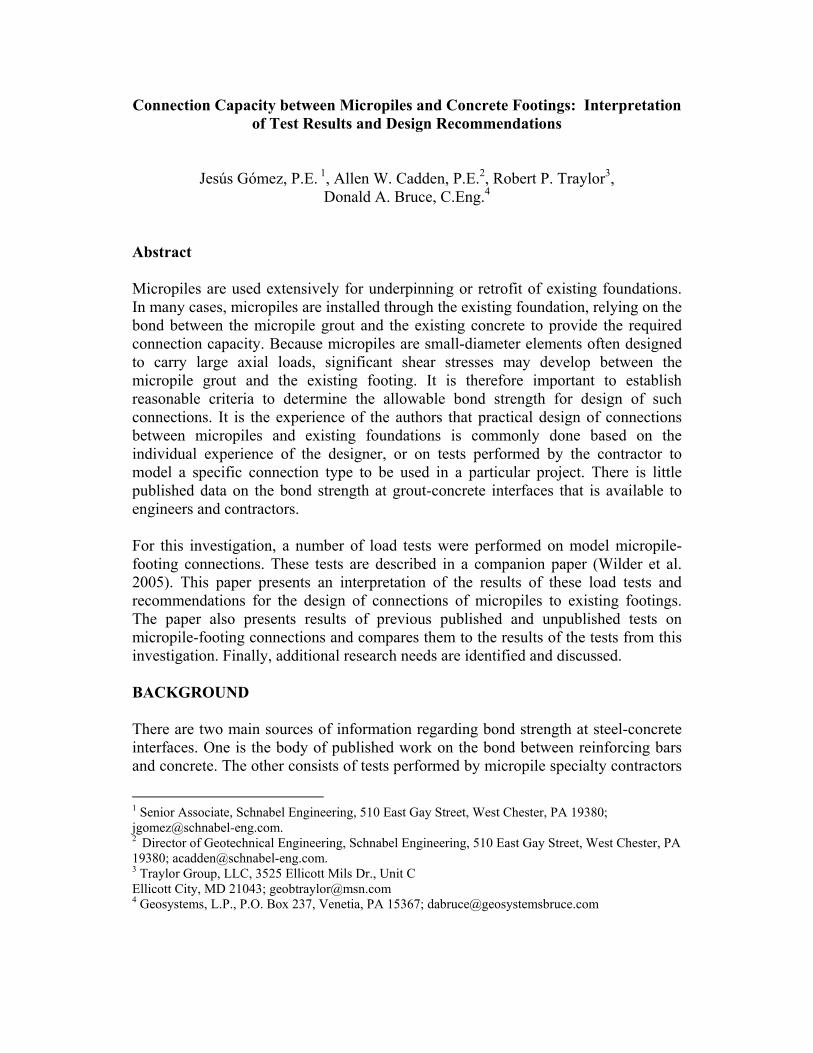
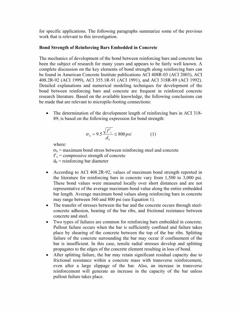
The tests did not consider intentional roughening or texturing of the predrilled hole other than that which occurs from percussive drilling, or the use of non-shrink grout in the annular space between the micropile insert and the concrete. The grout consisted of water and cement with a water:cement ratio of about 0.45. Tests on Smooth Casing Inserts Figure 1 is a simplified illustration of the configuration of smooth micropile inserts used for the tests in this research. The smooth inserts consisted of 4.5-inch diameter steel casing with a central 1.75-inch bar pre-grouted inside the casing. The inserts were inserted and grouted inside the predrilled hole using neat cement grout. Six- and eight-inch diameter holes were predrilled in the reinforced concrete block to receive the smooth inserts. A compressible inclusion at the bottom of each hole prevented development of end bearing during loading of the insert. For additional information and data on the tests, refer to Wilder et al. (2005). Upon application of the axial load on the insert, shear stresses were generated along the micropile-grout and grout-concrete interfaces. The shear stresses along the micropile-grout interface were larger than those along the grout-concrete interface due to its smaller perimeter. It is noted that the bearing stresses on the ground under the concrete block induce compression and tensile stresses around the upper and lower portions of the insert, respectively. As evidenced by strain gauge readings, shear stresses are not uniform along the insert. For the purposes of the interpretation of the load test data, average shear stresses along the insert-grout and grout-concrete interfaces are considered. Figure 2 reproduces the results of some of the tests on smooth micropile inserts performed for this investigation. In the figure, the deflection value shown
corresponds to the movement of the top of the insert. The bond stress corresponds to the mobilized shear stress along the micropile insert-to-grout interface.
Micropile Reinforced Concrete
Compressible Figure 1. Simplified Illustration of Smooth Inserts
0.0
100.0
200.0
300.0
400.0
500.0
600.0
700.0
800.0
0 0.05 0.1 0.15 0.2 Deflection (in)
Bon
d St
ress
at I
nser
t-Gro
ut In
terf
ace
(p
si)
Test 4-1, Hole Diameter=6 in,Insert Length=35 in
Test 4-2, Hole Diameter=6 in,Insert Length=23 in
Figure 2. Results of Tests on 4.5-inch Smooth Casing Inserts Grouted Within 6-inch Diameter Holes
The results of these tests reveal that the response of the insert to axial loading was initially stiff and linear until an insert head displacement of 0.03 to 0.04 inch was reached. The response of the insert to loading became nonlinear upon mobilization of an average bond stress of approximately 450 to 500 psi, which corresponds to 80 to 90 percent of the peak average bond strength. This point may correspond to the onset of slippage of the insert.
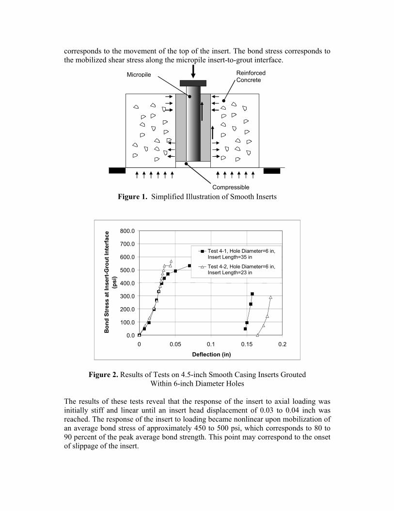
In all tests on smooth inserts, full failure of the connection developed after a deflection of the insert head less or equal to 0.05 inch. The average bond strength measured in the tests, defined as the point where full slippage of the insert takes place, was 530 to 570 psi. The measured deflection at the onset of failure seemed to be proportional to the length of the insert. During the tests, cracking noises often preceded failure. In most of the tests, failure of the insert was loud and dramatic with relatively large and quick displacements that often impeded accurate load or displacement measurement at failure, hence the discontinuity in the data presented in Figure 2. Failure of the connection was not accompanied by full loss of capacity. As evidenced in the figure, the residual shear stress calculated at the insert-grout interface was approximately 300 psi. The results shown on Figure 2 also suggest that the average bond strength did not vary significantly with the length of the insert. This is consistent with the results obtained in other tests performed for this research. Figure 3 reproduces the results of two tests performed on smooth inserts within the same concrete block. One of the inserts was grouted into a predrilled hole with a diameter of 6 inches. The other insert was grouted inside an 8-inch hole. It is noted that failure of the insert within the 6-inch hole took place upon mobilization of an average bond stress of 470 psi at the insert-grout interface. For the insert grouted in the 8-inch hole, failure took place at an average mobilized bond stress of 340 psi. In both tests, cracking noises preceded failure. An audible thump occurred at failure in both tests. These results seem to indicate that, for a constant insert diameter, the average bond strength measured at the insert-grout interface decreases with increasing diameter of the predrilled hole. Also, significant residual capacity of the connection after failure was measured in both tests. Cracking of the concrete block was not observed in any of the tests on smooth casing inserts.
0.0 100.0 200.0 300.0 400.0 500.0 600.0 700.0 800.0
0 0.05 0.1 0.15 0.2
Deflection (in)
Bon
d St
ress
at I
nser
t-Gro
ut In
terf
ace
(p
si)
Test 7-2, Hole Diameter=6in, Insert Diameter=4.5 in,Insert Length=22 inTest 7-1, Hole Diameter=8in, Insert Diameter=4.5 in,Insert Length=22 in
Figure 3. Results of Load Tests on Smooth Casing Inserts Grouted Within 6- and 8-
inch Diameter Holes

Tests on Casing Inserts Cast within Concrete Figure 4 summarizes the results obtained from load tests on smooth micropile inserts that were cast within the concrete block itself. In these tests, direct bond between the concrete and the insert surface was established. It is noted that the maximum bond stress ranged between 300 and 360 psi, which is significantly lower than that measured during tests performed on grouted inserts in 6-inch predrilled holes. The failure in the cast inserts, was not as dramatic as that of grouted inserts and significant slippage of the insert took place with a smaller drop in capacity. The residual shear stress after failure, calculated at the insert-concrete interface, was approximately 200 psi after a displacement of approximately 0.6 inch (not shown in the figure). Cracking of the concrete block was not observed in any of these tests.
0.0
100.0
200.0
300.0
400.0
500.0
600.0
700.0
800.0
0 0.05 0.1 0.15 0.2 Deflection (in)
Bon
d St
ress
at I
nser
t-Con
cret
e
Inte
rfac
e (p
si)
Insert Length = 17 inInsert Length=24 inInsert Length=35 in
Figure 4. Results of Load Tests on Smooth Casing Inserts Cast Within a Reinforced
Concrete Block Tests on Textured Casing Inserts Figure 5 is a simplified illustration of the configuration of micropile inserts textured with weld beads. As discussed by Wilder et al. (2005), the inserts consisted of 4.5-inch diameter steel casing with a central 1.75-inch bar. Weld beads were created with a 6-inch spacing along the insert, and with a width ranging between 1/4 and 1/2 inch. Each textured insert was grouted with neat cement grout inside a 6-inch diameter hole predrilled in the reinforced concrete block. For additional information and data on the tests, refer to the companion paper (Wilder et al. 2005). Weld beads were chosen only for purposes of this investigation due to ease of installation, large available shear capacity, and because installation inconsistencies are less likely than with conventional shear rings. It is noted that weld beads may not be practical or recommended for some practical applications.
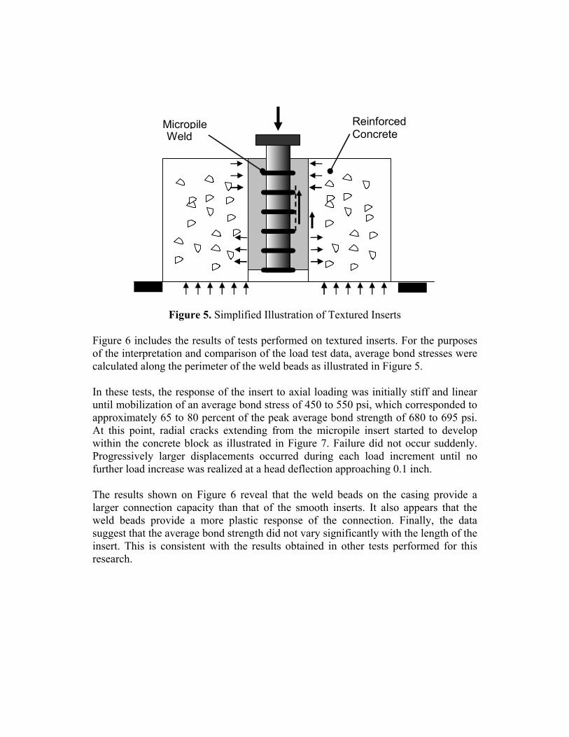
Micropile Reinforced Concrete Weld
Figure 5. Simplified Illustration of Textured Inserts Figure 6 includes the results of tests performed on textured inserts. For the purposes of the interpretation and comparison of the load test data, average bond stresses were calculated along the perimeter of the weld beads as illustrated in Figure 5. In these tests, the response of the insert to axial loading was initially stiff and linear until mobilization of an average bond stress of 450 to 550 psi, which corresponded to approximately 65 to 80 percent of the peak average bond strength of 680 to 695 psi. At this point, radial cracks extending from the micropile insert started to develop within the concrete block as illustrated in Figure 7. Failure did not occur suddenly. Progressively larger displacements occurred during each load increment until no further load increase was realized at a head deflection approaching 0.1 inch. The results shown on Figure 6 reveal that the weld beads on the casing provide a larger connection capacity than that of the smooth inserts. It also appears that the weld beads provide a more plastic response of the connection. Finally, the data suggest that the average bond strength did not vary significantly with the length of the insert. This is consistent with the results obtained in other tests performed for this research.

0.0
200.0
400.0
600.0
800.0
1000.0
1200.0
0 0.05 0.1 0.15 0.2 Deflection (in)
Bon
d St
ress
alo
ng W
eld
Bea
d
Perim
eter
(psi
)
Test 6-1, Insert Length = 35 in with Weld BeadsTest 6-2, Insert Length=23 in with Weld Beads
Figure 6. Results of Load Tests on Casing with Weld Beads Grouted Within 6-inch
Diameter Holes It is noted that an unload-reload cycle was performed after failure of the insert as illustrated in Figure 6. Upon reloading, the maximum mobilized bond stress was larger than during primary loading. For the purposes of this investigation, only the bond strength measured during primary loading is considered; however, it must be kept in mind that this increased bond strength during reloading may be due to rearrangement of fractured grout elements within the annular space.
Figure 7. Radial Cracks Extending from Test 6-2 Insert

Tests on Threadbar Inserts Tests were performed on micropile inserts that modeled the connection between a reinforced footing and a micropile with central bar reinforcement. The #14 SAS Stressteel bars were grouted inside 4.5-inch holes drilled through the concrete block. The bars were tested following similar procedures as for the casing inserts. The results of these tests are presented in Figure 8. The load-deflection response of the inserts was almost linear until the onset of failure. Failure of the insert took place dramatically, with sudden slippage of the bar, loss of jack pressure, and cracking of the concrete block. The maximum average bond stress mobilized during the tests was about 1,730 psi calculated at the nominal perimeter of the bar.
0.0 200.0 400.0 600.0 800.0
1000.0 1200.0 1400.0 1600.0 1800.0 2000.0
0 0.05 0.1 0.15 0.2 Deflection (in)
Bon
d St
ress
at i
nser
t-Gro
ut In
terf
ace
(p
si)
Test 2-2, #14 Stressteel Bar, Hole Diameter=4.5 in, Insert Length= 30 in Test 2-3, #14 Stressteel Bar, Hole Diameter=4.5 in, Insert Length=35.5 in
Figure 8. Results of Load Tests on SAS Stressteel Bars Grouted within 4.5-inch Holes
The average bond strength measured along the thread bars was significantly larger than that measured along smooth and textured casing inserts. It was also larger than the average values given by ACI for reinforcing bars in concrete subject to pullout (see Equation 1). However, it was consistent with reported maximum bond values measured at specific locations along reinforcing bars in concrete, as discussed previously in this paper. Interpretation of Strain Gauge Data As discussed in the companion paper (Wilder et al. 2005), strain gauges were installed in three of the inserts tested. The uppermost strain gauge in all instrumented tests, located near the point of application of the test load, did not yield reliable data,

probably due to small load eccentricities during the test. Consequently, the data from the uppermost strain gauge has been disregarded. Figure 9 illustrates the results obtained from the strain gauges installed on one of the textured casing inserts. Based on the variation of axial load along the insert, it is apparent that the mobilized bond stress decreases along the insert length. It can also be noted that upon unloading, locked-in axial stresses remain along the insert.
0
5
10
15
20
25
30
35
40
0 50 100 150 200
Axial Load (ton)
Dis
tanc
e fr
om T
op o
f Con
cret
e B
lock
(in)
Loaded to 116 tonUnloaded to 12 tonLoaded to 153 tonUnloaded to 12 tonLoaded to Failure
Upp
er
Segm
ent
Mid
dle
Seg
men
t Lo
wer
S
egm
ent
Figure 9. Variation of Axial Load along Textured Insert 6-1 Interpreted from Strain
Gauge Data The bond stresses mobilized along each of the instrumented inserts were calculated based on the axial load data and are presented in Figure 10. The estimated displacement at the insert-grout interface was calculated by adding the deflection measured at the head of the insert to the integrated strain measured along the insert.

0.0
100.0
200.0
300.0
400.0
500.0
600.0
700.0
800.0
900.0
1000.0
0.000 0.050 0.100 0.150 0.200
Interface Displacement (in)
Bon
d St
ress
(psi
) Upper SegmentMiddle SegmentLower Segment
(a) Smooth Casing Insert Within 6-inch Hole (Test 4-1)
0.0
100.0
200.0
300.0
400.0
500.0
600.0
700.0
800.0
900.0
1000.0
0.000 0.050 0.100 0.150 0.200
Interface Displacement (in)
Bon
d St
ress
(psi
) Upper SegmentMiddle SegmentLower Segment
(b) Smooth Casing Insert Within 8-inch Hole (Test 5-1)
0.0
100.0
200.0
300.0
400.0
500.0
600.0
700.0
800.0
900.0
1000.0
0.000 0.050 0.100 0.150 0.200
Interface Displacement (in)
Bon
d St
ress
(psi
) Upper SegmentMiddle SegmentLower Segment
(b) Textured Casing Insert Within 6-inch Hole (Test 6-1)
Figure 10. Bond Stress versus Displacement at the Insert-Grout
Interface Interpreted from Strain Gauge Data One important observation from Figure 10 is that the maximum and residual bond strength values decreased along the insert length. This is likely due to larger compressive stresses at the top of the concrete block and around the top of the insert, and possible generation of tensile stresses at the bottom.

In the tests on the smooth casing insert grouted within a 6-inch hole (Test 4-1), there was a significant drop in the bond strength. The smooth casing insert grouted within the 8-inch hole (Test 5-1) showed a lower bond strength than Test 4-1, and did not show a significant post-peak drop in bond strength. However, the residual bond strength in Test 4-1 was similar to the residual bond strength in Test 5-1. For the textured casing insert (Test 6-1), the bond strength was significantly larger, and did not decrease after failure of the connection. It is noted that these data are an average along a section of the insert and not representative of an individual location. The actual bond stress response at individual locations may differ from that illustrated in Figure 10. INTERPRETATION OF FACTORS CONTROLLING BOND STRENGTH The following observations are drawn from the results of the tests:
• For the types and dimensions of micropile inserts studied subject to axial compressive loads, the bond strength mobilized along the insert was larger near the top of the insert, where the load is applied, than at the tip of the insert. However, there was no significant or predictable influence of the insert length on the average mobilized bond strength.
• For micropile inserts grouted inside a hole predrilled through a concrete mass, the diameter of the hole appears to have a significant influence on the average bond strength that can be achieved. The results suggest that, for a constant insert diameter, the average bond strength decreases with hole size.
• Loading of the smooth inserts to failure did not induce visible cracking of the concrete block. Failure of textured inserts was accompanied by radial cracking of the concrete block.
• The average bond strength mobilized along inserts cast in concrete was generally lower than that of inserts grouted inside pre-drilled holes.
As discussed previously, the bond strength along a steel element embedded in concrete or grout consists of three components: adhesion, direct bearing on surface irregularities (texturing), and friction. During Test 4-1 (Figure 10) the bond strength reached a peak and then dropped to a residual value that persisted after relatively large interface displacements. It is conceivable that the drop in bond strength is mainly due to loss of adhesion and bearing, and that the residual response after large displacements is mostly frictional in nature. In the following paragraphs, the contributing factors to the frictional component of the bond strength are presented. This is primarily a qualitative attempt to understand the phenomenon of the bond strength along micropile inserts. Further experimental research would be necessary for a full understanding of the problem.

Frictional Component of the Bond Strength Figure 11 is an illustration of the theoretical response of a micropile-to-footing connection as interpreted by the authors and based on the results of the tests performed during this investigation. Three mechanisms are identified that contribute to friction around the micropile.
a. Friction induced at the top of the insert due to flexural stresses
b. Poisson effect
c. Dilation effect
Figure 11. Illustration of Three Mechanisms Inducing Friction at the Interface Between the Micropile Insert and the Surrounding Grout or Concrete
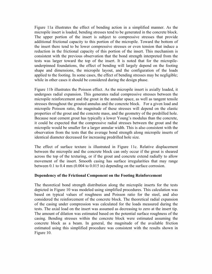
Figure 11a illustrates the effect of bending action in a simplified manner. As the micropile insert is loaded, bending stresses tend to be generated in the concrete block. The upper portion of the insert is subject to compressive stresses that provide additional frictional capacity to this portion of the micropile. Toward the bottom of the insert there tend to be lower compressive stresses or even tension that induce a reduction in the frictional capacity of this portion of the insert. This mechanism is consistent with the previous observation that the bond strength interpreted from the tests was larger toward the top of the insert. It is noted that for the micropile-underpinned foundations, the effect of bending will largely depend on the footing shape and dimensions, the micropile layout, and the configuration of the loads applied to the footing. In some cases, the effect of bending stresses may be negligible; while in other cases it should be considered during the design phase. Figure 11b illustrates the Poisson effect. As the micropile insert is axially loaded, it undergoes radial expansion. This generates radial compressive stresses between the micropile reinforcement and the grout in the annular space, as well as tangent tensile stresses throughout the grouted annulus and the concrete block. For a given load and micropile Poisson ratio, the magnitude of these stresses will depend on the elastic properties of the grout and the concrete mass, and the geometry of the predrilled hole. Because neat cement grout has typically a lower Young’s modulus than the concrete, it could be expected that the compressive radial stresses between the grout and the micropile would be smaller for a larger annular width. This is also consistent with the observation from the tests that the average bond strength along micropile inserts of identical diameter decreased for increasing predrilled hole size. The effect of surface texture is illustrated in Figure 11c. Relative displacement between the micropile and the concrete block can only occur if the grout is sheared across the top of the texturing, or if the grout and concrete extend radially to allow movement of the insert. Smooth casing has surface irregularities that may range between 0.1 to 0.4 mm (0.004 to 0.015 in) depending on the surface corrosion. Dependency of the Frictional Component on the Footing Reinforcement The theoretical bond strength distribution along the micropile inserts for the tests depicted in Figure 10 was modeled using simplified procedures. This calculation was based on typical values of roughness and Poisson ratio for the steel, and also considered the reinforcement of the concrete block. The theoretical radial expansion of the casing under compression was calculated for the loads measured during the tests. The axial load on the insert was assumed as decreasing to zero at the insert tip. The amount of dilation was estimated based on the potential surface roughness of the casing. Bending stresses within the concrete block were estimated assuming the concrete block as a beam. In general, the magnitude of the available friction estimated using this simplified procedure was consistent with the results shown in Figure 10.

For smooth inserts, the calculations suggest that bending stresses and Poisson effects control the magnitude of friction, and that the effect of the concrete block reinforcement is negligible. However, for textured inserts, the calculations suggest that the concrete block reinforcement may be stretched to or beyond its yield point. Therefore, significant confining stresses may develop that control the friction along the insert. This would also explain that there was no significant drop in the bond strength after large displacements of the textured inserts. It is observed that the radial tension cracks that developed during failure of the textured inserts had an approximate width of approximately 0.04 to 0.08 in (see Figure 7). The tensile strain that this displacement would generate within the reinforcing steel of the concrete block is estimated at about 0.5 to 1 percent, which would produce yielding of the steel. Considering that the reinforcing steel consisted of two #8 stirrups on each side of the insert, each bar had a yield point of about 47 kip, and the cracks extended to the bottom reinforcement, it would be reasonable to assume that the total confining force provided by the bars was at least 380 kip during failure of the insert. The overall connection capacity values measured during Tests 6-1 and 6-2 were 377 and 243 kip, respectively. These values are consistent with a confining force of 380 kip provided by the reinforcing steel, and a friction coefficient ranging from 0.6 to 1 between the textured insert and the grout. These experimental values tend to support the idea that the connection capacity of the textured inserts tested during this investigation was controlled by the confinement provided by the reinforcing steel of the concrete block. Although these calculations do not constitute a prediction and provide only a rough estimate of the frictional bond strength, they do illustrate the importance of bending stresses and Poisson effects for smooth inserts, and of surface texture and footing reinforcement for textured inserts. Effect of the Annular Space on Bond Strength Figure 12 summarizes the results of the tests performed on casing inserts during this investigation. The results of tests performed by others, which were discussed previously in this paper, are also included for comparison. The maximum average bond stress mobilized during the tests was calculated at the insert-grout interface. In casing inserts with weld beads or shear rings, the perimeter of the insert-grout interface was considered at the outer edge of the beads or rings.

0
100
200
300
400
500
600
700
800
0 0.2 0.4 0.6 0.8 1 1.2 1.4 1.6 1.8 2
Annular Width (in)
Ave
rage
Bon
d St
ress
at I
nser
t (ps
i)
Smooth Casing Inserts Grouted in Drilled Hole
Smooth Casing Inserts Cast in Concrete
Textured Casing Inserts Grouted in Drilled Hole
Casing Inserts w/Shear Rings and Non-Shrink Grout in Drilled Hole (Myers 2004)
Figure 12. Experimental Relationship between Average Bond Strength along
Grouted Inserts in Concrete, and the Annular Width around the Insert The figure reveals a clear decrease in the mobilized bond strength with increasing width of the grout-filled annular space around the insert. The shaded region in the figure is considered representative of the tests performed, and may serve as a design guideline for estimation of the average bond strength along smooth casing inserts grouted within predrilled holes in concrete, and subject to monotonic compressive loading. It is important, however, to recognize that the trend illustrated in the figure should be adjusted if the compressive strengths of the grout and the concrete are significantly different from those of the materials used in this investigation. The decrease of bond strength with increasing annular space may be due to the lower stiffness of the grout. As discussed previously, the frictional component of the bond strength is significant. Considering the simplified mechanism depicted in Figure 11, if the width of the grout-filled annulus increases, the normal stresses around the insert would decrease due to the lower grout stiffness. Consequently, the frictional component would decrease. As discussed previously, it is common to relate the bond strength along reinforcing bars cast in concrete to the square or cube root of the compressive strength of the concrete and to the reciprocal of the bar diameter (see Equation 1). However, it was found that such a relationship cannot be established from the tests performed and the data available in the literature. Based exclusively on the results of the tests performed for this investigation, the following relationship is obtained:
aa b ⋅−≤≤⋅− 200700200600 σ (2)

where σb is the average bond strength at the insert-to-grout interface in pounds per square inch, and a is the width in inches of the grout-filled annular space around the casing. This expression is applicable for a values ranging from 0.25 to 2 inches. The designer should include a suitable factor of safety over the bond strength values given by Equations 1 and 2. Equation 2 is only valid for smooth casing inserts, grouted within a predrilled hole through an existing concrete mass using neat cement grout with a 28-day compressive strength of at least 4,000 psi. This equation is not applicable to cored holes, and is not applicable to smooth casing inserts cast within concrete. It is noted that, for non-reinforced or lightly reinforced footings, this equation may be unconservative. For design of smooth micropile inclusions with a grouted annular space larger than 2 inches, it may be appropriate to apply Equation 1 using the compressive strength of the grout and the diameter of the casing. Considering the average grout compressive strength measured for the tests in this investigation, and a casing diameter of 4.5 inches, Equation 1 yields a value of bond strength of 175 psi. This value may be somewhat conservative; however, it is consistent with the results of the tests on smooth inserts embedded in unconfined grout described previously, where the bond strength ranged from 84 to 247 psi. Load testing of specific connection arrangements should be performed when the assumed ultimate bond capacity is large. The authors recommend that load testing be performed if the ultimate bond strength assumed for design is larger than 250 psi and the annular space width is on the order of one inch. The range of bond strength values shown in Figure 12 should be taken into account by the designer when deciding whether or not testing is warranted. It is also noted that the data in Figure 12 shows significant scatter for each set of tests performed under similar conditions. The designer should be aware of this scatter when selecting the number of load tests for a particular project. Influence of Surface Texturing on the Bond Strength of Grouted Inserts Figure 12 also includes the results of the tests performed on casing inserts with weld beads. It is observed that, for the same width of the grouted annular space around the insert, the weld beads provided additional bond strength with respect to that of smooth inserts. These results, together with those given by Myers (2004), which are also shown on the figure, seem to fit the trend of decrease of the average bond strength along the insert for increasing width of the grouted annular space. This trend cannot be confirmed unequivocally from these results, and further research on this issue is warranted. The additional bond strength provided by texturing (i.e., weld beads or shear rings around the casing) is due mainly to the increased frictional stresses around the insert. As discussed previously, texturing induces a wedge or splitting action within the

reinforced concrete mass. The normal compressive stresses that develop on the casing surface generate increased frictional shear stresses. The magnitude of these shear stresses will depend, among other factors, on the stiffness of the grout/concrete mass and the maximum radial tensile stresses that can develop. It is not possible to establish a generic relationship to calculate the available bond strength along textured micropile inserts because its value is strongly controlled by the geometry and reinforcement of the existing footing. The designer should estimate a reasonable value of bond strength considering yielding of the reinforcing steel surrounding the micropile and the resulting confining stress on the micropile. The confinement provided by the reinforcing steel will depend, among other factors, on the distance of this steel to the surface of the insert, the rebar distribution, and the geometry of the footing. A friction factor of 0.5 may be a reasonable estimate for this type of calculation. Testing of such connections is important in order to validate the preliminary bond strength estimates. CONCLUSIONS The connection capacity between micropiles and existing footings depends on several factors. The strength of the grout and the footing concrete will control the adhesion between the micropile and the footing. For smooth cased micropiles, the connection capacity is controlled by adhesion and friction between the steel and the grout and between the grout, and the concrete. The adhesion between the casing and the grout is likely controlled by the strength of the grout. After failure, the adhesion becomes zero and the connection capacity is controlled by friction only. Bending stresses within the footing, Poisson effects, and surface roughness are contributing factors to the frictional bond strength along smooth micropiles. For textured micropiles, the connection capacity is mostly controlled by frictional effects due to the large dilation that takes place during relative movement at the grout-steel interface. The splitting action induced by shear rings will typically induce yielding of the reinforcement steel of the footing. It was found that, for cased micropiles with shear rings, the frictional effect provided by the footing reinforcing steel may be estimated using the total yield capacity of the reinforcing steel multiplied by a friction factor. Bar inserts provide a total connection capacity similar to that of the textured casing inserts. This is probably because the connection capacities of the bars and the textured inserts were controlled by yielding of the footing steel rather than by the hole diameter and grout strength. Therefore, no expression for bond strength along the perimeter of the threaded bar is given. Smooth casing inserts cast within the concrete showed a connection capacity that was lower than that of grouted inserts. This surprising fact is explained by a lower

adhesion between the concrete and the steel due to the presence of the aggregate within the concrete. Also, frictional effects may not be as significant because of the relatively large scale of the concrete aggregate with respect to the surface texture of the smooth casing. ACKNOWLEDGEMENTS The authors would like to recognize the following sponsors for providing personnel and materials for conducting this testing program: Schnabel Engineering, Inc.; PKF-Mark III Inc.; Clark Arvig & Traylor, LLC; Numa Drilling; Geokon Inc.; L.B. Foster; and SAS StressSteel Inc. Without the generous contributions of time and materials by all partners in the industry, advancement of the state of the practice would not be possible. We would also like to thank Hayward Baker, Nicholson Construction Company, and Layne GeoConstruction for providing valuable information on bond strength tests. REFERENCES ACI 2003, ACI 408R-03, Bond and Development of Straight Reinforcing Bars in Tension ACI (1999), ACI 408.2R-92, State-of-the-Art Report: Bond Under Cyclic Loads (Reapproved 1999) ACI (1992), ACI 318R-89, Building Code Requirements for Reinforced Concrete and Commentary (Revised 1992) ACI (1991), ACI 355.1R-91, State-of-the-Art Report on Anchorage to Concrete Jokiniemi, Hannu, (2003), R&D from Rautaruukki’s Point of View, International Workshop on Micropiles, Seattle, WA Myers, Timothy, (2004), Layne GeoConstruction. Project testing. Personal communications in 2005 Richards, Tom, (2004), Nicholson Construction Company, Project testing. Personal communications in 2005. Sehn, Al, (1998), Hayward Baker, Inc. Research work. Personal Communications in 2005. Wilder, Darrel, Jesús Gómez, Allen W. Cadden, Robert P. Traylor, and Mike Pilkington. (2005). “Compressive Load Transfer in Micropiles through Concrete Footings: A Full Scale Test Program.” Companion paper in Geo3 Conference Proceedings.


