Connecting the MAX31855 Thermocouple Amplifier breakout to an ...
20
Connecting the MAX31855 Thermocouple Amplifier breakout to an Electric Imp Created by Joel Wehr Last updated on 2014-12-16 12:00:22 PM EST
-
Upload
vuongduong -
Category
Documents
-
view
217 -
download
0
Transcript of Connecting the MAX31855 Thermocouple Amplifier breakout to an ...
Connecting the MAX31855 Thermocouple Amplifier breakout to anElectric Imp
Created by Joel Wehr
Last updated on 2014-12-16 12:00:22 PM EST

2359
1218
Guide Contents
Guide ContentsOverviewBreadboarding the circuitGet the Device codeConfigure the Agent for XivelyConfigure the Agent for Twitter
© AdafruitIndustries
https://learn.adafruit.com/connecting-the-max31855-thermocouple-amplifier-breakout-to-an-electric-imp
Page 2 of 20
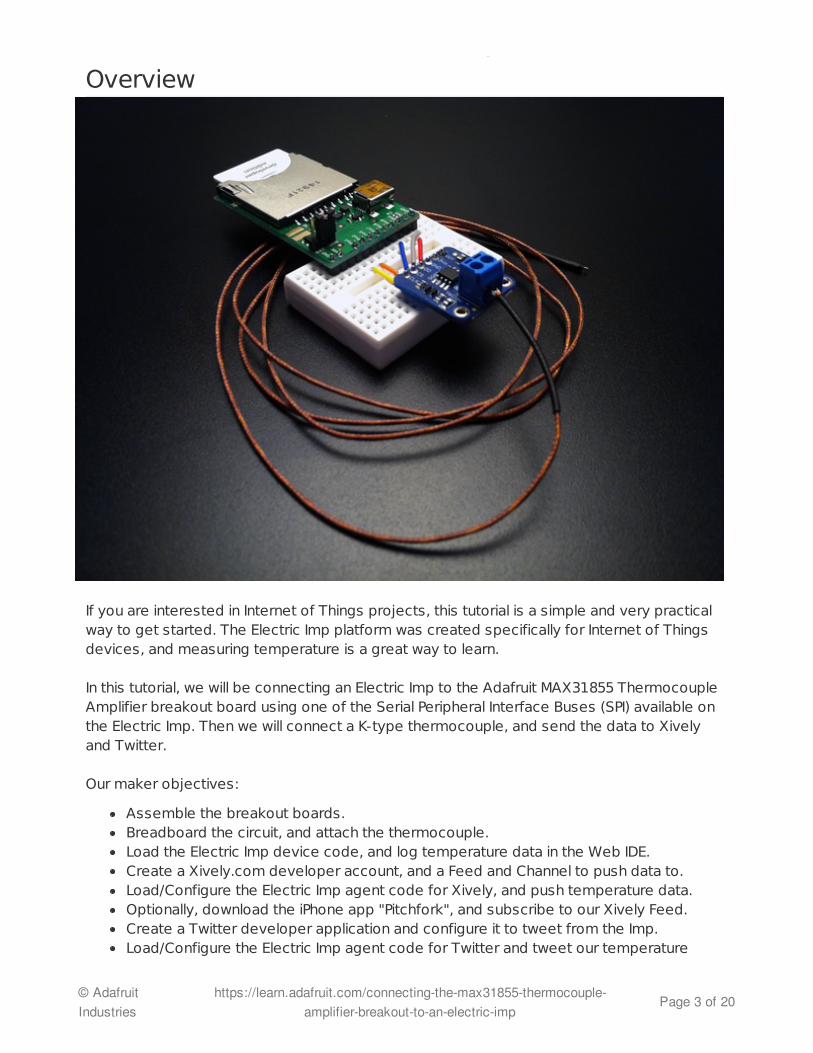
Overview
If you are interested in Internet of Things projects, this tutorial is a simple and very practicalway to get started. The Electric Imp platform was created specifically for Internet of Thingsdevices, and measuring temperature is a great way to learn.
In this tutorial, we will be connecting an Electric Imp to the Adafruit MAX31855 ThermocoupleAmplifier breakout board using one of the Serial Peripheral Interface Buses (SPI) available onthe Electric Imp. Then we will connect a K-type thermocouple, and send the data to Xivelyand Twitter.
Our maker objectives:
Assemble the breakout boards.Breadboard the circuit, and attach the thermocouple.Load the Electric Imp device code, and log temperature data in the Web IDE.Create a Xively.com developer account, and a Feed and Channel to push data to.Load/Configure the Electric Imp agent code for Xively, and push temperature data.Optionally, download the iPhone app "Pitchfork", and subscribe to our Xively Feed.Create a Twitter developer application and configure it to tweet from the Imp.Load/Configure the Electric Imp agent code for Twitter and tweet our temperature
© AdafruitIndustries
https://learn.adafruit.com/connecting-the-max31855-thermocouple-amplifier-breakout-to-an-electric-imp
Page 3 of 20

data.
Our learning objectives:
Understand how to configure and use SPI on the Electric Imp.Electric Imp pin configuration: http://devwiki.electricimp.com/doku.php?id=imppinmux (http://adafru.it/cEB)Read up on SPI here:http://en.wikipedia.org/wiki/Serial_Peripheral_Interface_Bus (http://adafru.it/cEC)Understand how to connect to and read from the MAX31855 thermocouple amplifier.MAX31855 datasheet:http://www.adafruit.com/datasheets/MAX31855.pdf (http://adafru.it/aLh)Understand how thermocouples work.http://learn.adafruit.com/thermocouple/overview (http://adafru.it/cED)Learn how to create a Xively feed and push data to it.Learn how to create a Twitter developer application and tweet from the Electric Imp.
Thermocouples are really great for extreme temperatures! Here are some projects ideas.
BBQ/Grill/Smoker temperature monitorOven temperature monitorHomebrewing temperature monitor (Mashing, chilling, boiling, fermenting, ect)SMT reflow oven temperature monitor/controlFridge/Freezer/Kegerator temperature monitorSoldering Iron temperature monitor
© AdafruitIndustries
https://learn.adafruit.com/connecting-the-max31855-thermocouple-amplifier-breakout-to-an-electric-imp
Page 4 of 20

Breadboarding the circuitLet's get started creating our Internet of Things temperature monitor!
FAQ: Are there two versions of the Electric Imp?Yes. Pictured below are the imp001 on the left, and the imp002 on the right. The imp001fits into most SD card sockets and contains all of the hardware to "Blink-Up" or connect toyour wireless network. The imp002 is a solder down version and allows the developer tocreate a custom "Blink-Up" circuit. All 12 pins are available with the imp002. We will beusing the imp001 for this tutorial, since it contains all of the circuitry to get us going.
This tutorial assumes that your Electric Imp isconnected to your WiFi network, (Blinked-Up), and that you have access to the ElectricImp Web IDE, which is currently in open beta.If you haven't, head on overto www.electricimp.com, sign up and followthe commissioning process directions.Alternatively, check out this really niceInstructable by Matt Haines from ElectricImp.
http://www.instructables.com/id/Getting-Started-with-Electric-Imp/
When your Electric Imp is connected andhappily blinking green, you are ready to getstarted.
If for some reason you have trouble getting connected, the best way to get help is topost on the Electric Imp forums from your developer account. Electric Imp staff andforum members post and reply day and night, so you'll get help right away.
First we need to assemble the thermocouplebreakout board. From the strip of 0.1" maleheader provided, snip a piece with 6 pins,and insert it into the board. An easy way toholder the header into place is to use apiece of masking tape. From one edge ofthe board, tape up and over the pins andback to the other edge. Then solder each
© AdafruitIndustries
https://learn.adafruit.com/connecting-the-max31855-thermocouple-amplifier-breakout-to-an-electric-imp
Page 5 of 20
FAQ: What is an impee?Any device or breakout board that is powered by an Electric Imp is called an "impee". TheApril impee is one of the reference designs created by Electric Imp for developer use.You can check out the other designs here:
http://devwiki.electricimp.com/doku.php?id=boards:start (http://adafru.it/cEV)
These designs also include a Bill of Materials (BOM) and Gerber files, in case you want totry your hand at printing and assembling the boards yourself.
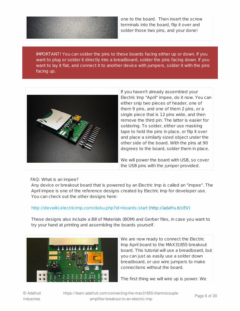
one to the board. Then insert the screwterminals into the board, flip it over andsolder those two pins, and your done!
IMPORTANT! You can solder the pins to these boards facing either up or down. If youwant to plug or solder it directly into a breadboard, solder the pins facing down. If youwant to lay it flat, and connect it to another device with jumpers, solder it with the pinsfacing up.
If you haven't already assembled yourElectric Imp "April" impee, do it now. You caneither snip two pieces of header, one ofthem 9 pins, and one of them 2 pins, or asingle piece that is 12 pins wide, and thenremove the third pin. The latter is easier forsoldering. To solder, either use maskingtape to hold the pins in place, or flip it overand place a similarly sized object under theother side of the board. With the pins at 90degrees to the board, solder them in place.
We will power the board with USB, so coverthe USB pins with the jumper provided.
We are now ready to connect the ElectricImp April board to the MAX31855 breakoutboard. This tutorial will use a breadboard, butyou can just as easily use a solder downbreadboard, or use wire jumpers to makeconnections without the board.
The first thing we will wire up is power. We
© AdafruitIndustries
https://learn.adafruit.com/connecting-the-max31855-thermocouple-amplifier-breakout-to-an-electric-imp
Page 6 of 20

The Electric Imp has two sets of pins for SPI. Those sets are pins 1,8 & 9, and pins 2,5 & 7.For this tutorial we will be using SPI189 as it is referred to in hardware configuration. Whenyou configure SPI189 you get the following pin configuration in the Electric Imp.
PIN 1 - CLK or ClockPIN 8 - MOSI (Master Out/Slave In)PIN 9 - MISO (Master In/Slave Out) or Data Out
This line of code configures SPI189 in the device:
hardware.spi189.configure(MSB_FIRST | CLOCK_IDLE_LOW , 1000);
Since we will only be reading data from the MAX31855 board (slave), we only need toconnect the MISO pin, which is pin 9, and not MOSI. We also need Pin 1 to provide a clocksignal, and one more pin to act as a Chip Select (CS) pin. In order to tell the MAX31855 thatwe want to read SPI data, we pull the CS pin LOW, read the data, and then set the pin back toHIGH. We can configure any of the other pins as a CS pin, so we will use Pin 2, since it isdirectly across from the CS pin.
This code reads SPI data from the chip that is connected to Pin 2:
hardware.pin2.write(0); //pull CS LOW to start the transmission of temp datalocal temp32=hardware.spi189.readblob(4);//SPI read is totally completedherehardware.pin2.write(1); // pull CS HIGH
Note: You can read as many chips as you like from a single SPI bus, as long as you have aChip Select Pin for each. Using just the April board, you could read up to four MAX31855chips. This is very handy for a project with multiple thermocouples.
To complete the wiring, connect these pins as shown above.
will be powering the April board with 5.0Vfrom a USB power supply, and so we willhave 5.0V available at the VIN pin. However,the Electric Imp itself runs at 3.3V, so we willalso have 3.3V available at the 3V3 pin. TheMAX31855 breakout has an onboard voltageregulator, and can be powered by either 3.3vat the 3Vo pin, or higher voltages at the Vinpin. Only connect power to one pin. For thiscircuit, we will use 3.3V from the April. Asshown in the image, connect the 3V3 pin onthe April to the 3Vo Pin on the MAX31855breakout, then connect the GND pins oneach board.
© AdafruitIndustries
https://learn.adafruit.com/connecting-the-max31855-thermocouple-amplifier-breakout-to-an-electric-imp
Page 7 of 20
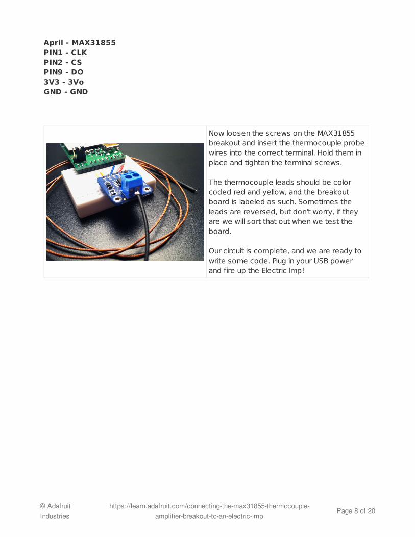
April - MAX31855PIN1 - CLKPIN2 - CSPIN9 - DO3V3 - 3VoGND - GND
Now loosen the screws on the MAX31855breakout and insert the thermocouple probewires into the correct terminal. Hold them inplace and tighten the terminal screws.
The thermocouple leads should be colorcoded red and yellow, and the breakoutboard is labeled as such. Sometimes theleads are reversed, but don't worry, if theyare we will sort that out when we test theboard.
Our circuit is complete, and we are ready towrite some code. Plug in your USB powerand fire up the Electric Imp!
© AdafruitIndustries
https://learn.adafruit.com/connecting-the-max31855-thermocouple-amplifier-breakout-to-an-electric-imp
Page 8 of 20

Get the Device codeElectric Imp: The agent and the device
One of the really interesting things about the Electric Imp is that you are able to programboth the device, and something called an "agent", which is a secure, programmable webservice that you use to interface with your Electric Imp device. If you are coming from aplatform like Arduino, you may be wondering why you can't talk directly to the Electric Impitself. That question is beyond the scope of this tutorial, but I have found that the agent is avery handy service to have. Here are a few great features of agents:
Communicate using HTTPSAdditional memory and processing power for codeIf you device goes offline, your agent will continue to execute code and can informyou.
As an example of the last point, if you use an Electric Imp in a security system, and a thiefdisables your connection or the device, your agent can still alert you that there is a problem.
The device can operate without any programming in the agent, so the first thing we need todo is program the device to read data from our thermocouple amplifier via SPI.
Log into your Electric Imp account and open the Web IDE. Find the Electric Imp that you willbe using by its hardware address in the list of your Devices on the left hand side. Mouseover it, and click the gear symbol to create new Device Settings. Click the down arrowbeside associated model, and then type a new model name, such as "MAX31855".
© AdafruitIndustries
https://learn.adafruit.com/connecting-the-max31855-thermocouple-amplifier-breakout-to-an-electric-imp
Page 9 of 20
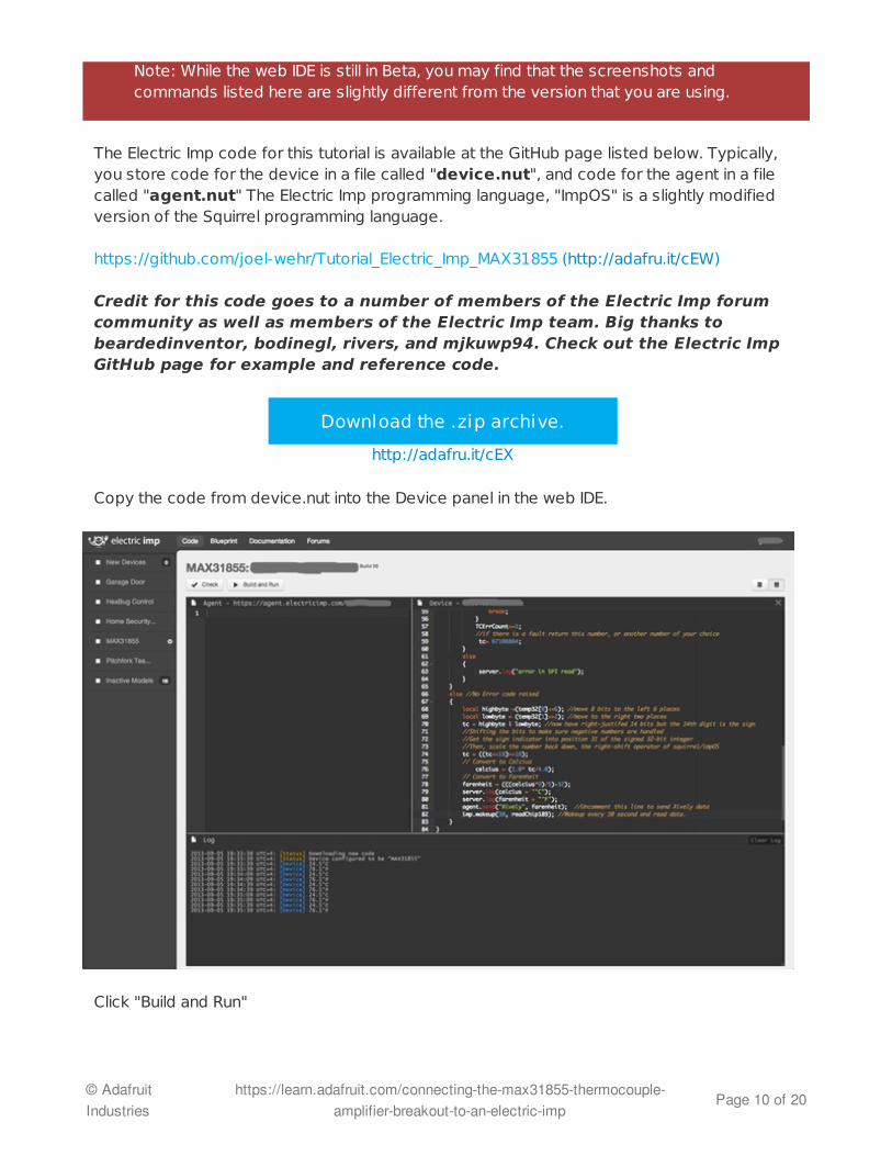
The Electric Imp code for this tutorial is available at the GitHub page listed below. Typically,you store code for the device in a file called "device.nut", and code for the agent in a filecalled "agent.nut" The Electric Imp programming language, "ImpOS" is a slightly modifiedversion of the Squirrel programming language.
https://github.com/joel-wehr/Tutorial_Electric_Imp_MAX31855 (http://adafru.it/cEW)
Credit for this code goes to a number of members of the Electric Imp forumcommunity as well as members of the Electric Imp team. Big thanks tobeardedinventor, bodinegl, rivers, and mjkuwp94. Check out the Electric ImpGitHub page for example and reference code.
Download the .zip archive.
http://adafru.it/cEX
Copy the code from device.nut into the Device panel in the web IDE.
Click "Build and Run"
Note: While the web IDE is still in Beta, you may find that the screenshots andcommands listed here are slightly different from the version that you are using.
© AdafruitIndustries
https://learn.adafruit.com/connecting-the-max31855-thermocouple-amplifier-breakout-to-an-electric-imp
Page 10 of 20

If all is well, you should see the Imp download the new code, and start logging data every 10seconds like this:
2013-09-04 21:33:28 UTC+4: [Status] Downloading new code2013-09-04 21:33:28 UTC+4: [Status] Device configured to be "MAX31855"2013-09-04 21:33:28 UTC+4: [Device] 24.5°C2013-09-04 21:33:28 UTC+4: [Device] 76.1°F
Nice! The Electric Imp is reading our thermocouple data over SPI!
If you haven't read through LadyAda's tutorial on thermocouples, amplifiers and the Seebeckeffect, I highly recommend that you do. Working with thermocouples will make much moresense.
http://learn.adafruit.com/thermocouple/overview (http://adafru.it/cED)
Troubleshooting: If you are getting unexpected data from your thermocouple, firstmake sure that the leads are fully secured in the screw terminals. Hold the end of thethermocouple in your hand, and check to see if the temperature reading rises. If itdoesn't, or goes lower, swap the red and yellow thermocouple leads and try again.
If you "Check" your code, it will attempt to compile, and you will see an X in a red boxby the lines of code that throw an error. If you "Build and Run" your code and errorsoccur, check the log for the line number that threw the error.
© AdafruitIndustries
https://learn.adafruit.com/connecting-the-max31855-thermocouple-amplifier-breakout-to-an-electric-imp
Page 11 of 20

Configure the Agent for Xively
The Electric Imp is a really great microcontroller in a tiny package, but its true purpose is toconnect devices to the Internet, so lets get to it!
It seems that there are new services to push your data to every week! One of those hasbeen around for a while and is now called Xively. You may have known it when it was Cosm,or Pachube. Let's set it up to log and graph our data.
If you haven't already, go to https://xively.com/signup/ (http://adafru.it/cEZ) and create afree developer account.
After you are set up and logged in, Click the DEVELOP tab, and +Add Device.
Give your device a name, a description, and then choose a privacy setting. For now, choosePrivate Device as we will be working with API keys.
Click Add Device.
Please Note: Xively no longer has free developer access to their system, so thistutorial is only for historical research. Please check out our other IoT tutorials foralternative services!
© AdafruitIndustries
https://learn.adafruit.com/connecting-the-max31855-thermocouple-amplifier-breakout-to-an-electric-imp
Page 12 of 20

Take a look around at your new Xively feed. The first thing we need to do is create a channelto push our thermocouple data to. Click the blue "+ Add Channel" bar.
Fill out the channel information.
To type the degree symbol "°":
© AdafruitIndustries
https://learn.adafruit.com/connecting-the-max31855-thermocouple-amplifier-breakout-to-an-electric-imp
Page 13 of 20
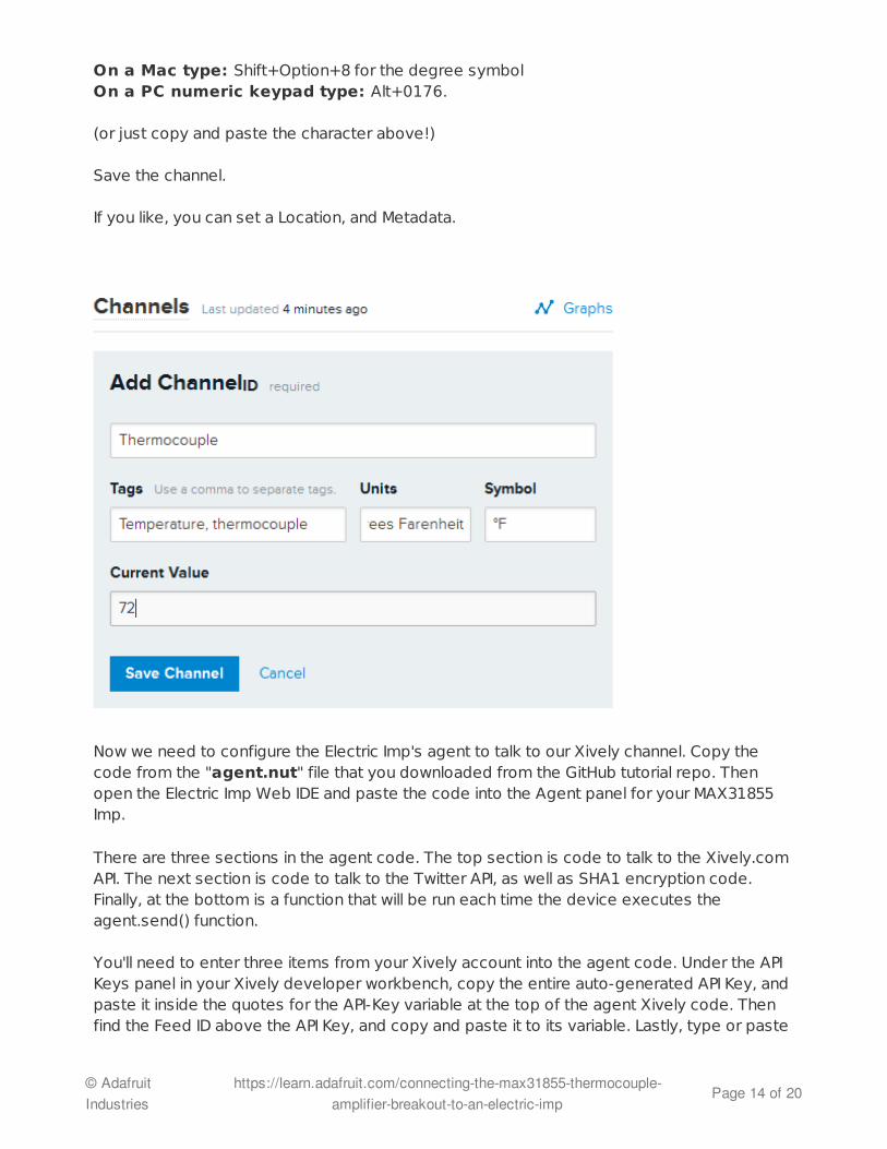
On a Mac type: Shift+Option+8 for the degree symbol On a PC numeric keypad type: Alt+0176.
(or just copy and paste the character above!)
Save the channel.
If you like, you can set a Location, and Metadata.
Now we need to configure the Electric Imp's agent to talk to our Xively channel. Copy thecode from the "agent.nut" file that you downloaded from the GitHub tutorial repo. Thenopen the Electric Imp Web IDE and paste the code into the Agent panel for your MAX31855Imp.
There are three sections in the agent code. The top section is code to talk to the Xively.comAPI. The next section is code to talk to the Twitter API, as well as SHA1 encryption code.Finally, at the bottom is a function that will be run each time the device executes theagent.send() function.
You'll need to enter three items from your Xively account into the agent code. Under the APIKeys panel in your Xively developer workbench, copy the entire auto-generated API Key, andpaste it inside the quotes for the API-Key variable at the top of the agent Xively code. Thenfind the Feed ID above the API Key, and copy and paste it to its variable. Lastly, type or paste
© AdafruitIndustries
https://learn.adafruit.com/connecting-the-max31855-thermocouple-amplifier-breakout-to-an-electric-imp
Page 14 of 20

the name of your channel into the Channel_ID variable. My channel was named"Thermocouple". This section of code looks like:
API_Key <- "YOUR API KEY"; //Type your Xively API KeyFeed_ID <- "YOUR FEED ID" //Type your Feed IDChannel_ID <- "YOUR CHANNEL ID"; //Type your Channel ID
The Xively API Key sections looks like this:
Now, in the Device code panel, uncomment line 81 or the line that has this code:
agent.send("Xively", farenheit); //Uncomment this line to send Xively data
Build and Run your code, and you should see something like this:
2013-09-04 22:44:21 UTC+4: [Status] Device booting2013-09-04 22:44:21 UTC+4: [Status] Device configured to be "MAX31855"2013-09-04 22:44:21 UTC+4: [Device] 24.5°C2013-09-04 22:44:21 UTC+4: [Device] 76.1°F2013-09-04 22:44:21 UTC+4: [Agent] { "id": "Thermocouple", "current_value": 76.1 }
Take a look at your Xively channel. You should see the Electric Imp begin sending data tothe feed in the Request Log, and the data should show up in your channel and on the graph.
Nice! You are sending thermocouple data to Xively!
Troubleshooting: Make sure you copied all the information correctly. Check the API Keyto make sure it has "create" privileges. It should by default, but if it doesn't you'll needto create one that does. "Read" privileges are not enough.
© AdafruitIndustries
https://learn.adafruit.com/connecting-the-max31855-thermocouple-amplifier-breakout-to-an-electric-imp
Page 15 of 20

Now, what if you wanted to monitor this dataon your iPhone or iPad? Search for an appcalled Pitchfork in the App Store. This appwas created to work with the Electric Impand Xively. Find the Xively Data panel, and
© AdafruitIndustries
https://learn.adafruit.com/connecting-the-max31855-thermocouple-amplifier-breakout-to-an-electric-imp
Page 16 of 20

enter the settings for your API key, Feed andChannel into the app. Now, everytime youopen that panel, the app will subscribe toyour feed and update every time there isnew data. The app allows you to configure asingle feed with up to two channels. Nowyou can keep an eye on your temperaturefrom anywhere!
When you are comfortable with Xively, takea look at Triggers. You can set triggers foreach channel to enable actions on events.For more fun, take a look at Zapier.com. Youcan hook Xively triggers to Zapier "Zaps"and perform all kinds of cool actions.
© AdafruitIndustries
https://learn.adafruit.com/connecting-the-max31855-thermocouple-amplifier-breakout-to-an-electric-imp
Page 17 of 20

Configure the Agent for TwitterNext, let's set up our Electric Imp to tweet its temperature! You'll need a Twitter account, sogo ahead and create one of you haven't already. In order to tweet from our Imp's agent, wewill need to access the Twitter Developer Center.https://dev.twitter.com/apps/new (http://adafru.it/cF0)
Fill out the Name, Description, and Website information. Agree to the terms and conditions,and complete the Captcha. If all is well, Twitter will create an new application for you.
Take a look at what is on the page. At the bottom, click "Create my Access Token". Twitterwill create Access tokens for you.
I have found that I need to click the buttons to create Access Tokens, and to changethe Application Type twice before it updates properly. Ensure that you have what youneed before moving on.
© AdafruitIndustries
https://learn.adafruit.com/connecting-the-max31855-thermocouple-amplifier-breakout-to-an-electric-imp
Page 18 of 20

The token created is read-only, and we need to give it write access. Click on the Settingstab at the top. Scroll down to Application Type, and check "Read and Write". Then click"Update this Twitter application's settings" at the bottom. Make sure it updates to "Read andWrite".
Now go back to the Details tab. We need to update our Access Token. Click "Recreate myaccess token" at the bottom. Make sure it says "Read and Write" after you update it.
We now have all the information we need to tweet. From the Details tab in your Twitterapplication page, carefully copy the appropriate information into the variables near thebottom of your Agent code in the Electric Imp Web IDE. You'll need to fill out these variables:
_CONSUMER_KEY <- "YOUR KEY"_CONSUMER_SECRET <- "YOUR SECRET"_ACCESS_TOKEN <- "YOUR TOKEN"_ACCESS_SECRET <- "YOUR SECRET"
Paste your information inside the quotes.
© AdafruitIndustries
https://learn.adafruit.com/connecting-the-max31855-thermocouple-amplifier-breakout-to-an-electric-imp
Page 19 of 20

Finally, uncomment this line near the end of the Agent code:
//twitter.update_status("The temperature is: " + v + "F.");
imp.wakeup(10, readChip189); //Wakeup every 10 second and read data.
Click "Build and Run" in the web IDE. Check the log, if you don't see any errors you havetweeted successfully. Check your Twitter account for the message.
If you do see error messages, check all of your keys and tokens for accuracy, and try again.
Congrats! Your Electric Imp can tweet! Don't forget to send a tweet to @adafruit and@electricimp!
Stay tuned for an upcoming tutorial on building a dual probe thermocouple temperaturemonitor with LCD readout using the Adafruit Arduino enclosure.
If you let this code run, your Imp will tweet every 10 seconds! To avoid spamming yourTwitter followers and only execute once, comment out this line in the device code:
© Adafruit Industries Last Updated: 2014-12-16 12:00:24 PM EST Page 20 of 20