Connecting Leslie 1 - Hammond X66 Organ Club · Connecting Leslie to X-66 Dec 2011 dan.vigin Page 3...
24
Connecting Leslie to X-66 Dec 2011 dan.vigin Page 1 Hammond X-66 Connecting Leslie cabinet to Hammond X-66 Console by Dan.Vigin Hammond® and Leslie® are registered trademarks of Suzuki Musical Instrument Manufacturing Co. Ltd. Binche / Belgium Dec.2011
Transcript of Connecting Leslie 1 - Hammond X66 Organ Club · Connecting Leslie to X-66 Dec 2011 dan.vigin Page 3...

Connecting Leslie to X-66 Dec 2011 dan.vigin
Page 1
Hammond X-66
Connecting Leslie cabinet to Hammond X-66 Console
by Dan.Vigin
Hammond ® and Leslie ® are registered trademarks of Suzuki Musical Instru ment Manufacturing Co. Ltd.
Binche / Belgium Dec.2011

Connecting Leslie to X-66 Dec 2011 dan.vigin
Page 2
TABLE OF CONTENTS 1. Forewords & Purpose of this project P. 3 2. General Description P. 4 3. Block-Diagram P. 6 4. Description of circuits P. 7
4.1 Mixing Stage P. 7
Shematic Diagram P. 8
4.2 Leslie Booster – Unbalanced output P. 9
4.3 Leslie Booster – Balanced output P.11
4.4 Connecting cable and wiring P.12 Wiring Diagram P.13 4.5 Power ON circuit P.14 4.6 Fast/Slow Motor circuit P.15 4.7 Audio Input circuit P.16 4.8 Connecting cable P.17
5. Adjustment Procedure P.18 6. Final Tips P.20
7. Conclusions P.24

Connecting Leslie to X-66 Dec 2011 dan.vigin
Page 3
Connecting Leslie to Hammond X-66. 1. Forewords – Purpose of this Project There are several ways to connect a Leslie cabinet to the Hammond X-66 console. In the X-66 service manual, on Fig. A-6 (page A-9), we find the schematic diagram of a 'Monophonic Mixer' composed of four transistors and including Bass/Treble tone controls. This monophonic mixer has been built with more recent components and results were not satisfactory for two reasons: - output level is insufficient to drive a Leslie cabinet with adequate 'swing' - while being totally shielded, hum and noise level remains too high So, this first approach was dropped. A better alternative is fully described in the chapter ' Connecting X-66 ' starting from page 12. In this solution, the input level to drive a Leslie cabinet is more adequate, the hum and noise level is also improved while not being optimized. The audio mixer provides a lot of possibilities that can be really helpful to the player. Needless to mention that routing the Leslie signal through an audio mixer provides the optimum flexibility to balance the levels of each X-66 channel to your own wishes. Nevertheless, the residual hum and noise level was still high to my opinion. The purpose of this third proposal is to obtain the optimal results in terms of : - high input level to drive any Leslie cabinet - optimize the hum and noise reduction - improve the safety regulations aspect It has to be noted that this new way of connecting a vintage Leslie cabinet is not peculiar to the Hammond X-66 console and with minor modifications can be easily adapted by any qualified technician to other Hammond organs. Unfortunately, once again, some mechanical adaptations are required and a Leslie booster unit has to be built in order to achieve those performances. In this configuration, the Leslie tone cabinet remains always connected to the Hammond X-66 while it is quite possible to switch ON/OFF the audio signal with minor modifications. See 'Final Tips'. The motor speed control has been already extensively developed in a previous chapter and is available as 'Motor Control Circuit' on the website in the Annexes of 'Restoring part'. This last attempt of connecting a Leslie cabinet to Hammond X-66 offers real improvements in terms of hum and noise and a boosting effect to Leslie that was never felt before. Of course, other 7-pin sockets available at the X-66 output receptacle remain unaltered to drive on either TC-1277 cabinets or any other external audio mixer.

Connecting Leslie to X-66 Dec 2011 dan.vigin
Page 4
2. General Description. We know that Draw 'A' and Draw 'B' signals available from the X-66 Console are almost identical. As a consequence of this, since the intention is to drive a monophonic Leslie cabinet, in this case, only Draw 'A' signal has been selected because it contains more components such as Pedal Vibrato, Tabs Tremulants than Draw 'B' channel. The two others signals are 'Tabs' and 'Reverb' and have to be present as well. The Tabs signal is compulsory to be also there since it merges also other signal sources such as Pedal Bass signals and Traps keyer. The Reverb signal includes a 'mixture of everything' to assure the reverb effect. So, basically we have to extract three signal from the Expression board AO-32186-1 in order to drive the Leslie cabinet with adequate signals sources. Those three signal sources are therefore routed to a mixer stage which mission is to adapt the levels as wished. The output signal out of this mixer stage becomes so 'monophonic' and is directly connected to a Leslie booster unit which in turn drives later on the input of the Leslie tone cabinet via a connecting cable. Up to there, nothing really innovative indeed. However, if one wants to go for a more sophisticated way, it appears that a lot of noise is generated by the connecting cable between the X-66 Console and the Leslie cabinet. Why ? As a matter of fact, the connecting cable between the X-66 Console and the Leslie cabinet is also carrying 230 V AC Mains which is, to my opinion, a wrong approach for two reasons:
- audio wires are even not shielded and are induced by the electrical field of the AC Mains wires. Just by connecting the Leslie cable on the X-66 Console end without being connected at the other Leslie end, it's quite easy to record a 50Hz induced signal of more than 30 Vpp ! Some may argue on this since the load at Leslie end is 'infinite' while this high level at the audio signal. Correct, but this leads us to conclude that anyhow this unwanted interference signal is well present in this cable and the only solution to minimize this induced signal is to reduce by all means the impedance of the source itself (i.e. the X-66 in this case). That's exactly the intention of adding this built-in Leslie booster.
- on a safety regulation standpoint, this link carrying both AC Mains and other signals in the same cable is not at all in line with actual safety regulations, at least in Europe. In addition to that, those Amphenol male/female connectors currently used for Leslie links are really 'out of date' and, sorry to say, not very professional, nor reliable. The AC Mains link in this new approach is now fully separated from the other signals feeding the tone cabinet.
The above statement is not specific to the X-66 Console connected to Leslie cabinet but applicable for other vintage Hammond models.

Connecting Leslie to X-66 Dec 2011 dan.vigin
Page 5
Based on above considerations, the following principles have been applied: - Audio cable is now duly shielded and totally separated from the AC Mains
leads. This cable is also carrying other DC command signals. - Source impedance of the audio signal coming out from the X-66 Console has been reduced to a very low value in the range of 100 ohms ! This means about 50 times lower than the output impedance of the Output Board AO-32186-1 of the X-66 console. - AC Mains cable feeding the Leslie cabinet is now totally separated avoiding so any possible induction of the audio signal and meeting the safety regulations.
CONNECTING X-66 WITH LESLIE TONE CABINET
HAMMOND X-66 CONSOLE
Hammond ® and Leslie ® are registered trademarks of Suzuki Musical Instrument Manufacturing Co. Ltd.
Date : 28/11/2011 Issued by : Dan.Vigin
LESLIE 147
AC Mains cable
AC Mains
AC Mains cable
Special cable carrying:- Audio signal from X-66 Console- Fast/Slow motor speed command- Leslie power ON/OFF command

Connecting Leslie to X-66 Dec 2011 dan.vigin
Page 6
3. Block-Diagram. The simplified Block diagram hereunder exhibits a better view of this project.
X-66 Expression & Output Board
AO-32186-1Mixing Stage
Booster Stage
Fast/SlowMotor Ctr.Circ.
X-66 Power Supply Unit
5-pinXLR
Draw’A’, Tabs & Reverb signals
MonophonicAudio signal
- 14Vdc
+/-30Vdc
Boosted Mono Audio signal
F/S Command
Shielded Cable
AC Mains
F/S MotorCircuit
Audio InputCircuit
Power ONCircuit
F/S Motors
Leslie Amp.PSU
External Input (¼ ‘‘ TS plug)
Leslie Amp.Circuit
5-pinXLR
5-pinXLR
5-pinXLR
S
S
P
P
Boosted Mono Audio signal
Power ONCommand
X-66 Console
Leslie Amplifier
TDA7294

Connecting Leslie to X-66 Dec 2011 dan.vigin
Page 7
4. Description of circuits. The highlighted parts of the block-diagram will be analysed here after. 4.1. Mixing Stage. This stage is probably the simplest one in this project. Its function is to extract from the Expression & Output board of the X-66 console the most relevant elements to be routed as a monaural signal to the Leslie cabinet. Refer to the drawing 'Leslie Booster for Hammond X-66' on the left hand side of the schematic diagram on the next page. Not so much to say about this Mixer Stage. The level of each signal sources coming from the Expression Control board is mixed via their respective potentiometer. Signals are slightly buffered and merged via resistors R1', R2' and R3' in a monaural way to be connected to the input of the Leslie Booster. For proper adjustment purpose and long term stability, it is strongly recommended to use multi-turns potentiometer as P1, P2 and P3 for this function. The correct adjustment procedure will be detailed in the next pages. Due its simplicity, those passive components are just installed on one stripboard (with continuous copper strips) just nearby the Leslie booster. See photo hereunder.

Connecting Leslie to X-66 Dec 2011 dan.vigin
Page 8
B+
8.2K
+ -
22K
680
1N40
07
IN
UN
BA
LAN
CE
D
OU
TP
UT
TD
A72
9415
0
10K
100/5W
+-
100
nF(C
er.)
100
nF(C
er.)
100K + -
+
10K
33K
10/1
W
22µ
F 4
0V10
0µF
40V
15
3.3
nF
2.2µ
F 6
3VN
P
22µ
F 2
5V
47µ
F 5
0V
1N40
07
1N41
48
B- -3
0Vdc
+30V
dc50
mA
dc
50 m
Adc
OF
F
Mut
ing
Std
-By
B+
1
2 34
5
6
7 89
101112
13
14
N/C
N/C
N/C
D1
GN
DG
ND
-
D3
C1
C2
C3
C5
C6
C7
R1
R2
C8
R3
R4
R5
R6
R7
R8
R9
R10
SW
1
D2
50K
4.7k
50K
4.7k
50K
10 K
LES
LIE
BO
OS
TE
R
DR
AW
‘A’
TA
BS
RE
VE
RB
Fro
m E
xpre
ssio
n C
ontr
ol B
oard
AO
-320
66-1
Unb
alan
ced
audi
o si
gnal
to
Les
lie
cabi
net
MIX
ING
ST
AG
E
P1
P2
P3
R1'
R2'
R3'
Not
es:
P1,
P2,
P3
: mul
ti-tu
rns
Lin
pot.
D2,
D3
: pro
tect
ion
flyba
ck d
iode
s.R
4 : o
vera
ll ga
in a
djus
tmen
t pot
.IC
1 : a
dequ
ate
heat
sink
man
dato
ry (
see
dats
heet
)S
W1
: opt
iona
l sw
itch,
Pt.C
(ca
thod
e of
D1)
can
be
dire
ctly
con
nect
ed to
B+
T1
: P/N
HS
-612
2XF
MR
from
Ham
mon
d S
uzuk
i ( L
eslie
ref
.: 04
8025
ava
ilabl
e at
ww
w.to
new
heel
gene
ral.c
om )
or
equi
v.A
ll re
sist
ors
are
¼ w
att u
nles
s ot
herw
ise
spec
ified
.N
P =
non
-pol
ariz
edN
/C =
not
con
nect
ed
OU
T
Lesl
ie B
oost
er fo
r H
amm
ond
X-6
6F
ile: L
eslie
_Boo
ster
.vsd
D
ate
: 07/
12/2
011
Is
sued
by
: Dan
.Vig
in
Ham
mon
d®
and
Les
lie®
are
reg
iste
red
trad
emar
ks o
f Suz
uki M
usic
al In
stru
men
t Man
ufac
turin
g C
o. L
td.
A B
C
DR
AW
‘A’
LEV
EL
AD
JUS
T.
TA
BS
LEV
EL
AD
JUS
T.
RE
VE
RB
LE
VE
L A
DJU
ST
.
T1
BLK
RE
DR
ED
YE
L
YE
L/R
ED
Wiri
ng fo
r ba
lanc
ed a
udio
sig
nal (
Lesl
ie 1
22 f.
i.)10
/1W
A BG
ND
Com
mon
(+ve
) ho
t
(-ve
) co
ld
IC1
RT
A
Mon
o A
udio
S
igna
l
GN
D
Connecting Leslie to X-66 Dec 2011 dan.vigin
Page 9
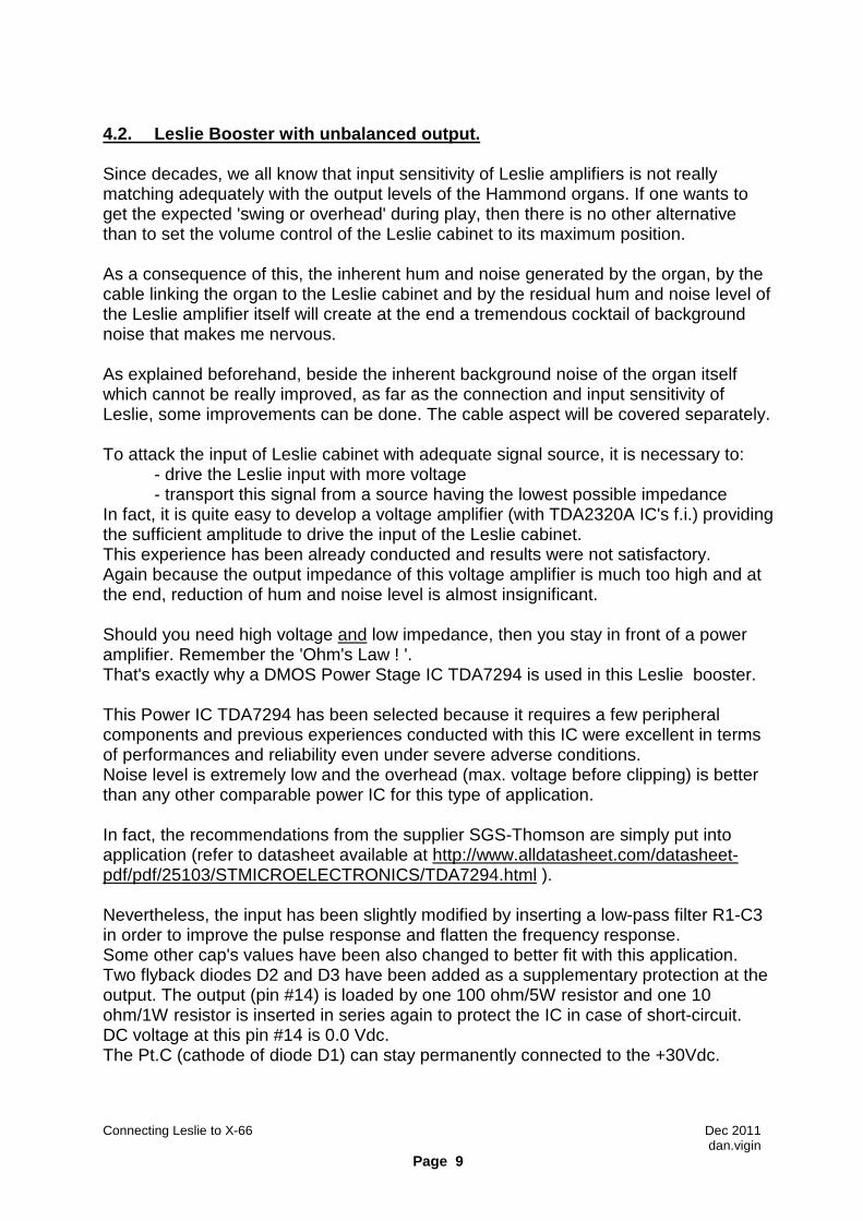
4.2. Leslie Booster with unbalanced output. Since decades, we all know that input sensitivity of Leslie amplifiers is not really matching adequately with the output levels of the Hammond organs. If one wants to get the expected 'swing or overhead' during play, then there is no other alternative than to set the volume control of the Leslie cabinet to its maximum position. As a consequence of this, the inherent hum and noise generated by the organ, by the cable linking the organ to the Leslie cabinet and by the residual hum and noise level of the Leslie amplifier itself will create at the end a tremendous cocktail of background noise that makes me nervous. As explained beforehand, beside the inherent background noise of the organ itself which cannot be really improved, as far as the connection and input sensitivity of Leslie, some improvements can be done. The cable aspect will be covered separately. To attack the input of Leslie cabinet with adequate signal source, it is necessary to: - drive the Leslie input with more voltage - transport this signal from a source having the lowest possible impedance In fact, it is quite easy to develop a voltage amplifier (with TDA2320A IC's f.i.) providing the sufficient amplitude to drive the input of the Leslie cabinet. This experience has been already conducted and results were not satisfactory. Again because the output impedance of this voltage amplifier is much too high and at the end, reduction of hum and noise level is almost insignificant. Should you need high voltage and low impedance, then you stay in front of a power amplifier. Remember the 'Ohm's Law ! '. That's exactly why a DMOS Power Stage IC TDA7294 is used in this Leslie booster. This Power IC TDA7294 has been selected because it requires a few peripheral components and previous experiences conducted with this IC were excellent in terms of performances and reliability even under severe adverse conditions. Noise level is extremely low and the overhead (max. voltage before clipping) is better than any other comparable power IC for this type of application. In fact, the recommendations from the supplier SGS-Thomson are simply put into application (refer to datasheet available at http://www.alldatasheet.com/datasheet-pdf/pdf/25103/STMICROELECTRONICS/TDA7294.html ). Nevertheless, the input has been slightly modified by inserting a low-pass filter R1-C3 in order to improve the pulse response and flatten the frequency response. Some other cap's values have been also changed to better fit with this application. Two flyback diodes D2 and D3 have been added as a supplementary protection at the output. The output (pin #14) is loaded by one 100 ohm/5W resistor and one 10 ohm/1W resistor is inserted in series again to protect the IC in case of short-circuit. DC voltage at this pin #14 is 0.0 Vdc. The Pt.C (cathode of diode D1) can stay permanently connected to the +30Vdc.

Connecting Leslie to X-66 Dec 2011 dan.vigin
Page 10
The resistor network composed of R3, R4 and R5 are defining the overall gain of this power IC. One multi-turns potentiometer is used as R4 for fine adjustment of the gain. Refer to the adjustment procedure in the next pages. Last but not least ! This power IC TDA7294 must be installed on heatsink, if not, it will blow after a few minutes of operation. Moreover, the tab of this IC is connected internally to the –Vs (or B-). So, either the IC is isolated from the heatsink with adequate insulator or the IC is directly installed on heatsink but heatsink has to be isolated from chassis ground. In my case, the heatsink is isolated from the metal support (more risky). All components are installed on a one-side epoxy board recuperated from a previous application. That's why PCB layout is not supplied in this chapter. The whole assembly composed of the Mixing Stage and Leslie Booster is installed on top of the Expression & Output board AO-32186-1 (renovated version) in such way to minimize the length of the wires. Shielded audio cable is used to connect the output of the Leslie booster to the X-66 outlet receptacle.
The amplitude of the exploitable voltage swing available at the output of this Leslie booster depends directly of the supply voltages B+ and B-. In this case, +30 Vdc and –30Vdc are coming from the X-66 PSU block. Addition of LM117 and LM337 regulators is needed. The max.operating voltage of IC TDA7294 is +/- 40Vdc, so it operates as such in very steady and safe conditions.
Connecting Leslie to X-66 Dec 2011 dan.vigin
Page 11
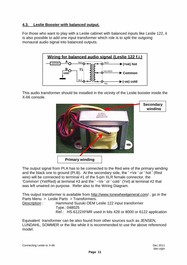
4.3. Leslie Booster with balanced output. For those who want to play with a Leslie cabinet with balanced inputs like Leslie 122, it is also possible to add one input transformer which role is to split the outgoing monaural audio signal into balanced outputs.
T1
BLK
RED RED
YEL
YEL/RED
Wiring for balanced audio signal (Leslie 122 f.i.)10/1W A
BGND Common
(+ve) hot
(-ve) cold
This audio transformer should be installed in the vicinity of the Leslie booster inside the X-66 console.
The output signal from Pt.A has to be connected to the Red wire of the primary winding and the black one to ground (Pt.B). At the secondary side, the ' +Ve ' or ' hot ' (Red wire) will be connected to terminal #1 of the 5-pin XLR female connector, the 'Common' (Yel/Red) at terminal #3 and the ' –Ve ' or ' cold ' (Yel) at terminal #2 that was left unwired on purpose. Refer also to the Wiring Diagram. This output transformer is available from http://www.tonewheelgeneral.com/ , go in the Parts Menu > Leslie Parts > Transformers. Description : Hammond Suzuki OEM Leslie 122 input transformer Type.: 048025 Ref.: HS-6122XFMR used in kits 428 or 8000 or 6122 application Equivalent transformer can be also found from other sources such as JENSEN, LUNDAHL, SOMMER or the like while it is recommended to use the above referenced model.
Primary winding
Secondary winding

Connecting Leslie to X-66 Dec 2011 dan.vigin
Page 12
4.4. Connecting cable and wiring. As announced earlier, the Amphenol socket of the X-66 outlet receptacle and plug of the Leslie cabinet have been removed and replaced by 5-pin XLR one's. On X-66 outlet console:
On the Leslie amplifier:
The wiring diagram on the next page provides the needed connecting points at both ends.

Connecting Leslie to X-66 Dec 2011 dan.vigin
Page 13
X-6
6 E
xpre
ssio
n &
Out
put B
oard
Rev
erb.
C
hann
el
Dra
w ‘A
’
Dra
w ‘B
’
Tab
s
GN
D
X-6
6 O
utle
t Rec
epta
cle A
C
Mai
ns
RE
D
WH
T
BLU
YE
L
BLU
GR
Y
Mix
ing
Sta
ge
Boo
ster
Sta
ge
To
X-6
6 P
SU
TD
A72
94
+30
Vdc -3
0 V
dc
GN
D
12 3
567
4
123
4 5
Circ
uit
Bre
akerTo
X-6
6 P
SU
-14V
dc
7-pi
n so
cket
(unb
alan
ced
inpu
t)
YE
L/G
RN
BLU
BLU
BLU
To
Fas
t/Slo
wM
otor
Con
trol
Circ
uit
Aud
io
GN
D
- 14
Vdc
N/C
XLR
cha
ssis
sock
etX
LRso
cket
Pow
er O
NC
omm
and
To
AC
M
ains
PO
WE
R O
N
CIR
CU
IT
123
4 5
XLR
ch
assi
s pl
ug
WIR
ING
DIA
GR
AM
INP
UT
C
IRC
UIT
FA
ST
/SLO
W
CIR
CU
IT
VIO
AO
-321
86-1
123
4 512
34 5
Shi
elde
d ca
ble
XLR
plug
BLU
BR
N
LN
Lesl
ie P
ower
Am
plifi
er
Ext
erna
l inp
ut
for
¼‘‘
TS
plu
g
N/C
Lesl
ie B
oost
er fo
r H
amm
ond
X-6
6F
ile: L
eslie
_Boo
ster
.vsd
D
ate
: 06/
12/2
011
Is
sued
by
: Dan
.Vig
in
Ham
mon
d®
and
Les
lie®
are
reg
iste
red
trad
emar
ks o
f Suz
uki M
usic
al In
stru
men
t Man
ufac
turin
g C
o. L
td.
GN
D
GN
D(P
oint
-to
-Poi
nt c
onne
cted
)
TA
R
To
X-6
6ci
rcui
ts
123
4 5
XLR
Fem
ale
Soc
ket
123
4 5
XLR
Mal
e P
lug
Fro
nt V
iew
GN
D
GN
D
GN
DGN
D

Connecting Leslie to X-66 Dec 2011 dan.vigin
Page 14
4.5. Power ON circuit. Since the Leslie cabinet is not powered anymore by the connecting cable of the X-66 console, a standard AC Mains socket has been installed as shown on the previous diagram. The 5-pin socket and plug P2/S2 on Leslie schematic that is totally useless nowadays has been removed as well and replaced by the original fuse holder. With today's components, it is quite easy to switch ON a remote equipment with a Solid State Relay (SSR for short).
Earth
1
23
4
5
XLRplug
820/0.5W
+
-4 1
23
FUSE 1.0 AT
To Power Transformer
L N
VDR 250 V
AC Mains- 14 Vdc - 13.3 Vdc
- 1.2 Vdc
15 mAdc
1N4007
POWER ON Circuit
SSR - Sharp - S202S02
In this case, the SSR S202S02 from Sharp is used (250 V, 8A) and is by far sufficient to switch ON a Leslie cabinet. The –14Vdc collected from the circuit breaker nearby the XLR socket on the X-66 outlet receptacle renders conducting the built-in LED of the SSR via one resistor of 820 ohm for adequate current flow (15 mAdc). The diode 1N4007 in series is assuring some protection in case of mishandling. This LED is energizing the triac devices like a mechanical switch and the Leslie amplifier stays ON until the X-66 console is switched ON. Quite simple. This system is fully safe since the built-in opto-coupler provides a total galvanic insulation between the AC Mains leads and the Leslie amplifier chassis. As recommended by Sharp supplier, one VDR – 250Vac is installed to eliminate unwanted spikes of AC Mains and protecting so the SSR. Of course, if required, it is quite possible to modify this single-pole switching ON system towards a bipolar one. A second SSR has to be added for the other phase (N) of the AC Mains with the adequate adaptations at the LED's end.

Connecting Leslie to X-66 Dec 2011 dan.vigin
Page 15
4.6. Fast/Slow Motor circuit. The F/S command (i.e. +8 Vdc to +10 Vdc for Fast and 0 Vdc for Slow) has been already fully described in a previous chapter and is not the object of this project. For short, the Fast or Slow commands to select either the Fast or Slow motors is issued from the DC voltage coming from the X-66 console.
S N F
Solid State Relay – SSR122B
heaters
115V-AC Neutral
To Slow Motors
YEL
6,3Vac
Static switching via triacs
GRN ORG WHT To Fast Motors
GND
BLK
13V 0.5W1
23
4
5
XLRplug GND
1N4007
Fast Speed: +8 to +10 VdcSlow Speed: 0 Vdc
P2
Triggercircuit
F/S Motor Control Circuit
D1
Z1
This DC voltage is applied to Pt. P2 of the Hamptone SSR122B board or equivalent (available from http:www.//bborgan.com/ ). The built-in trigger is switching either to Fast or to Slow motors according to the voltage applied to P2. This device is connected to heaters voltage (6.3 Vac) of the Leslie transformer. Diode D1 protects the SSR122B against mishandling. Zener diode Z1 is supposed to clip any voltage spike above 13 Vdc.

Connecting Leslie to X-66 Dec 2011 dan.vigin
Page 16
4.7. Audio Input circuit. As already explained, the Leslie cabinet can receive audio signals directly from the X-66 console. In this case, the audio signal will be carried by the newly developed cable via XLR connectors. With the addition of this new built-in Leslie booster, the output level available from the X-66 console can drive the Leslie amplifier with optimal 'swing' and minimal hum and noise. Nevertheless, this Leslie cabinet should be in position to also receive audio signals from an external audio mixer f.i. That's why an external TS socket is added on the Leslie chassis.
1
23
4
5
XLRplug
External input for ¼‘‘ TS plug
GNDInput
Selector
820
R5
R4X-66 DIRECT
10K
Log
½ V112AU7A
3 KG1A
1
2
8
C1
1.5 µF400V
EXT. SOURCE
S1
Input Level
AUDIO INPUT
LESLIEAMPLIFIERGND
The Leslie 'load resistor' switch is used to select either 'X-66 Direct' or 'Ext.Source'. Evidently the 8 ohm / 10 W resistors R2 and R3 as shown on the Leslie service manual are here again totally useless and removed. So, it is now possible to take benefit of this selector for this application. Capacitor C1 (1.5 µF / 400 V) is added to block any DC voltage at G1 of V1. Of course, the above solution is only valid for unbalanced Leslie input. Important notice. Since both X-66 Console and Leslie amplifier are connected by two separate AC Mains cables equipped each with 'Earth' lead, it may happen that a 'ground loop' be generated so via those earth leads. If this situation occurs one of the two earth points should be disconnected.

Connecting Leslie to X-66 Dec 2011 dan.vigin
Page 17
4.8. Connecting cable. Since the initial objective is to reduce the hum and noise level of the link between the X-66 console and the Leslie cabinet, to achieve this result, it makes sense to only use professional grade cable with proper shielding.
For that application, one 8 meters BELDEN cable ( Ref.: 1904A - 4PR24 ) was used. As mentioned, 5-pin XLR male and female connectors are pin-to-pin connected. Details are provided on the Wiring Diagram of Page 13.
Connecting Leslie to X-66 Dec 2011 dan.vigin
Page 18
5. Adjustment procedure. It goes without saying that an oscilloscope is mandatory if optimal results are expected. The adjustments have to be done in several sequences and are basic for any experienced technician. 5.1. Mixing stage (refer to schematic diagram on Page 8). Preliminary setting: before installing this Mixing Stage inside the X-66 Console, when still on the bench, it is advisable to set the three potentiometers P1 to P3 near the middle position. Due to this mixing concept, it is obvious that those potentiometers may interact to a certain extend between each others. 5.2. Setting the Gain of booster stage . Here again, before installing the booster in the X-66 Console, it is easier to setup the overall gain of the booster while still on the bench. The booster is powered by +/- 30 Vdc as indicated on the schematic diagram. Inject 100 mVrms sinewave signal @ 1 KHz at the input and adjust the potentiometer R4 for 3.0 Vrms at the output. The overall gain is then set to 30x. At the same time, monitor this operation with the scope at the output. 5.3. Setting Draw 'A' level . Conditions: - set drawbar 16' to position #8, Upper keyboard only - swell pedal at full blast - organ Volume on 'High' - depress permanently key #25 (middle of the Upper keyboard) - volume control of Leslie amplifier to '0'. Setting: under the above conditions, adjust P1 for about 50 mVrms (or 140 mVpp
on the scope) at the input of the booster. The ouput signal will be 1.53 Vrms (or 4.3 Vpp) with a overall gain set to 30x.

Connecting Leslie to X-66 Dec 2011 dan.vigin
Page 19
5.4. Setting Tabs level . Conditions: - set drawbar 16' to position zero or depress the Cancel preset
- set only 'Diapason' of ORCH Tab to ON of upper keyboard. - put Brilliance tab ON - swell pedal at full blast - organ Volume on 'High' - depress permanently key #25 (middle of the Upper keyboard) - volume control of Leslie amplifier remains to '0'
- Important: remove temporarily the belt from the scanner motor to stop the Celeste scanner. Since a small portion of the Tabs signals are 'rerouted' through the Celeste scanner, beats are displayed on the scope and it is almost impossible to perform any correct measurements.
- since Tabs signals are no more sinewave, only 'Vpp' readings on the scope have to be taken into consideration for Tabs adjustments.
Setting: under the above conditions, adjust P2 for about 200 mVpp at the Input of the booster. The output signal will be 6.0 Vpp (gain 30x). Remark: it is interesting to notice that Tabs level is about 5 time higher than sinewave signal found with Drawbar 16". In fact, when analyzing the Tabs signals, it easy to notice on the scope that it contains a lot of sharp spikes (or transients) that generate harmonics. However the duration of these transients is extremely short by comparison with a pure sinewave signal as it is the case with drawbar signals. If average measurements could be implemented (not possible with test-equipment on hand), surely the results would be very closed to each other. Anyhow, at the end, the human ear will evaluate if levels between Tabs and Drawbars are properly adjusted. 5.5 Overall and Reverb setting. Increase the Volume control of the Leslie cabinet to position #3 and you will feel at once the tremendous improvement in terms of hum and noise reduction and what I call 'Swing Reserve'. Reverb setting: it is quite difficult to adjust the Reverb level at potentiometer P3 with the scope. Engage the Reverb 1 Tab and slowly increase P3 to suit your hearing preferences. Some like more 'Reverb' than others. Just rotate P3 as you like keeping always an eye on the monitoring scope so that Draw 'A' and Tabs channels are not disrupted. If during listening tests, you are not satisfied with the overall results, this mixing stage offers a lot of flexibility to the player to balance the levels Draw 'A', Tabs and Reverb channels as wished.

Connecting Leslie to X-66 Dec 2011 dan.vigin
Page 20
Other points to be checked: - Pedal Keyboard: depress the middle 'C' pedal note. With the first 16' Pedal drawbar at position #8, keep this 'C' pedal depressed and switch 'Pedal Vibrato' tab from 'Normal' to 'Pedal Vibrato ON'. Monitor on the scope if levels are almost equal in amplitude. When this Pedal Vibrato tab is engaged, ideally the same level should be kept. - Similarly, with one or several ORCH tabs depressed to ON, check also if the overall level remains identical when ' ORCH Tremulant' tab is set to ON. 5.6 Final control. Connect the scope at the output (Pt.A of Leslie booster) and play normally with drawbars, orchestral tabs, percussions, pedals, etc... The max. output level obtainable under the most adverse playing conditions can never exceed 50 Vpp on the scope with supply voltages of +/-30 Vdc at the booster stage. Increasing B+/B- voltages up to +/- 40 Vdc will provide even more headroom whenever possible. If clippings appear on the scope and become audible, then rotate the potentiometer R4 (gain of booster) gradually just before any sign of clipping may arise. The gain of the booster will be somewhat reduced in this case. 6. Final Tips. - Switching OFF signals to Leslie cabinet : quite simple to install one inverter switch somewhere on the upper or lower manual to interrupt the input of the Leslie booster. This can be also done with an original Leslie half-moon Tremolo Control (Ref.103750). Shielded audio cables are always recommended. - Connecting board : while not being mandatory, for easiness of measurements and tests, one additional connecting board is installed near the Output board AO-32186-1. Two fuses (0.5A F) have been added to protect the Leslie booster. All audio wires are shielded. Draw'A' channel is loaded by the mixing stage feeding the Leslie booster but the Draw 'B' channel is left unloaded as such. Aa a consequence of this, the level of Draw 'B' channel available at the ouptut of the Expression board AO-32066-1 will be higher than the Draw 'A' channel. Since both channels 'A' and 'B' must provide identical levels for further connections with either TC-1277 or external audio mixer, it is therefore recommended to install one adjustable potentiometer of 10 K between the output of Draw 'B' channel and ground in order to adjust both levels accordingly. See Connecting Board drawing on next page.

Connecting Leslie to X-66 Dec 2011 dan.vigin
Page 21
CONNECTING BOARD.
0.5
AF
Fus
e
0.5
AF
Fus
e
Dra
w A
Tab
s
0.5
AF
0.5
AF
+24V
dc
-24V
dc
+24V
dc
-24V
dc
From Expression Board AO-32066-1
Dra
w B
Rev
erb
Out
put S
ocke
t #6
Out
put S
ocke
t #1
Out
put S
ocke
t #2
Out
put S
ocke
t #7
Ext
.Aud
io M
ixer
‘T’
Ext
.Aud
io M
ixer
‘A’
Ext
.Aud
io M
ixer
‘B’
Ext
.Aud
io M
ixer
‘R’
Lesl
ie B
oost
er ‘T
’
Lesl
ie B
oost
er ‘A
’
Lesl
ie B
oost
er ‘R
’
From PSU
OUTPUT CONNECTING PANEL
Fus
e
Fus
e
danv
i_11
1206
+30V
dc
-30V
dc
GN
D
-30V
dc
+30V
dc
To VCA BoardTo Booster
RED RED
RE
D
RE
D
BLU
BLU BLK
BLK
BLU BLU BLK
GNDGND+ + +
GND
BLK
To
VC
A B
oard
GND
POT.10K

Connecting Leslie to X-66 Dec 2011 dan.vigin
Page 22
- PSU for Leslie Booster : inevitably, some modifications have to be undertaken to feed the +/- 30 Vdc voltages for the Leslie booster. Additional standard components have to be added in the original X-66 PSU block. See how it looks inside the X-66 PSU block hereunder.
Pot.1.5K 2W
LM117
LM337 Pot.1.5K
2W

Connecting Leslie to X-66 Dec 2011 dan.vigin
Page 23
Schematic diagram : addtional PSU for Leslie Booste r.
Remark: it has to be noted that this Leslie booster can be used in many other applications when one wants to get additional 'swing' or 'headroom' either with Leslie cabinets or other audio power systems and, beside the Mixing Stage, is not peculiar to the Hammond X-66 console. Problem is to be in position to find accurate +/- 30 Vdc from the built-in PSU.

Connecting Leslie to X-66 Dec 2011 dan.vigin
Page 24
7. Conclusions. Using the X-66 console powered by a static audio system in conjunction with a Leslie cabinet certainly offers to the player the greatest sound flexibility. This new direct way of connecting a Leslie cabinet with a built-in booster and separate AC Mains supply meets the expectations in terms of hum and noise reduction, optimal headroom (or swing reserve) with Leslie volume control in low (or middle) position and improved protection in terms of safety regulations. Last but not least, with the adjustments at the Mixing Stage and Leslie booster the user can also 'balance' the levels of his X-66 console according to his personal preferences. At the end, we all know that the human ear always remains the final decision-maker and will confirm whether or not it was worthwhile to do it. In my case, no doubt that this way of feeding my Leslie cabinet will remain as it. Trust having been of some help, Dan Vigin