CONFORMED-TO-CAD DESIGN SLOPED-EDGE ADAPTIVE SLICING€¦ · · 2015-06-22CONFORMED-TO-CAD DESIGN...
18
CONFORMED-TO-CAD DESIGN SLOPED-EDGE ADAPTIVE SLICING Mohammad Hayasi, Bahram Asisbanpour Ingram School of Engineering, 601 University Drive, Texas State University-San Marcos, 78666, Texas, USA Abstract Many mathematical and simulation based researches have shown the effectiveness of adaptive and angular slicing and layering in minimizing errors in layered manufacturing processes and improving surface quality and build time. Recent technological advances such as 5-axis laser cutters, abrasive waterjets, and CNC machines have enabled physical part fabrication beyond typical vertical layered manufacturing with staircase errors. In this paper, a new curved- form adaptive slicing method is presented. In this method, multiple cuts of the edge boundary of each adaptive layer with variable cutting vector angles conform well to CAD model curved surfaces. The proposed system is compatible with 5-axis abrasive waterjet machines. This system has been successfully tested on several virtual 3D CAD models. Keywords: Sloped-edge Adaptive Slicing, 5-Axis Cutting, Rapid Functional Part Fabrication, Rapid Tooling, Fully Dense Freeform Fabrication (FDFF) 1. Introduction Rapid prototyping (RP) processes, such as direct metal laser sintering (DMLS), fused deposition modeling (FDM), selective laser sintering (SLS), stereolithography (SLA), and 3D printing have been in commercial use for decades across many business sectors. The rapid fabrication of a Computer-aided Design (CAD) model independent of any tooling is appealing as it would significantly reduce time, effort and cost - all crucial factors to the success of any business. To build a rapid 3D prototype that geometrically matches its 3D CAD model, current commercial RP systems often apply very thin layers of metal foil, fine metal/ non-metal powder, or liquid resin laminating from the bottom to top of the CAD model such that steps appearing on the edges of the layered model become less significant. This, however, increases build time and thus fabrication cost. Thick-layer lamination with sloping surfaces offers a possible solution to overcome this problem by reducing the number of layers. Mechanical limitations of the commonly used RP systems make thick-layer building impossible. This is due to the fact that fusing, sintering, soldering, ultrasonic welding, and printing of the dense collection of particles and molecules in any selected bulk region of a variable thick layer is unachievable using present technology. Methods of building functional metallic parts and tooling by means of abrasive waterjet and laser cutting of fully dense metal sheets in various thicknesses followed by alignment and attachment of layers have recently been developed (Nakagawa and Kunieda, 1984; Vouzelaud et al., 1992; Glozer and Bervick, 1992;Walczyk and Hardt ,1996; Bryden et al., 2001; Glen et al., 2011). The ability to rapidly cut various sheet metal thicknesses from small to large dimensions using abrasive waterjet or laser cutter machines helped to significantly reduce build time 689
Transcript of CONFORMED-TO-CAD DESIGN SLOPED-EDGE ADAPTIVE SLICING€¦ · · 2015-06-22CONFORMED-TO-CAD DESIGN...

CONFORMED-TO-CAD DESIGN SLOPED-EDGE ADAPTIVE SLICING
Mohammad Hayasi, Bahram Asisbanpour
Ingram School of Engineering, 601 University Drive, Texas State University-San Marcos,
78666, Texas, USA
Abstract
Many mathematical and simulation based researches have shown the effectiveness of
adaptive and angular slicing and layering in minimizing errors in layered manufacturing
processes and improving surface quality and build time. Recent technological advances such as
5-axis laser cutters, abrasive waterjets, and CNC machines have enabled physical part fabrication
beyond typical vertical layered manufacturing with staircase errors. In this paper, a new curved-
form adaptive slicing method is presented. In this method, multiple cuts of the edge boundary of
each adaptive layer with variable cutting vector angles conform well to CAD model curved
surfaces. The proposed system is compatible with 5-axis abrasive waterjet machines. This system
has been successfully tested on several virtual 3D CAD models.
Keywords: Sloped-edge Adaptive Slicing, 5-Axis Cutting, Rapid Functional Part Fabrication, Rapid
Tooling, Fully Dense Freeform Fabrication (FDFF)
1. Introduction
Rapid prototyping (RP) processes, such as direct metal laser sintering (DMLS), fused
deposition modeling (FDM), selective laser sintering (SLS), stereolithography (SLA), and 3D
printing have been in commercial use for decades across many business sectors. The rapid
fabrication of a Computer-aided Design (CAD) model independent of any tooling is appealing as
it would significantly reduce time, effort and cost - all crucial factors to the success of any
business. To build a rapid 3D prototype that geometrically matches its 3D CAD model, current
commercial RP systems often apply very thin layers of metal foil, fine metal/ non-metal powder,
or liquid resin laminating from the bottom to top of the CAD model such that steps appearing on
the edges of the layered model become less significant. This, however, increases build time and
thus fabrication cost. Thick-layer lamination with sloping surfaces offers a possible solution to
overcome this problem by reducing the number of layers. Mechanical limitations of the
commonly used RP systems make thick-layer building impossible. This is due to the fact that
fusing, sintering, soldering, ultrasonic welding, and printing of the dense collection of particles
and molecules in any selected bulk region of a variable thick layer is unachievable using present
technology. Methods of building functional metallic parts and tooling by means of abrasive
waterjet and laser cutting of fully dense metal sheets in various thicknesses followed by
alignment and attachment of layers have recently been developed (Nakagawa and Kunieda,
1984; Vouzelaud et al., 1992; Glozer and Bervick, 1992;Walczyk and Hardt ,1996; Bryden et al.,
2001; Glen et al., 2011).
The ability to rapidly cut various sheet metal thicknesses from small to large dimensions
using abrasive waterjet or laser cutter machines helped to significantly reduce build time
689
bjf
Typewritten Text
REVIEWED, Accepted August 15, 2012

compared to RP approaches that employed very thin layers of material. Fully dense rapid
prototypes that are built up from non-uniform (adaptive) layers suffer from staircase errors
appearing on the boundary edges of the layered CAD model (Figure 1).
Figure 1. Illustration of the magnitude of geometry deviation error using simple adaptive slicing
The sloped-edge adaptive slicing approach could improve the part quality to some extent
but it still results in a geometry distortion error (staircase) even on sloping edges (Figure 2).
Figure 2. Illustration of the magnitude of geometry deviation error using sloped-edge adaptive slicing
To improve conformity to CAD model geometry, curved-form adaptive slicing on the
sloped edges is presented. Multiple cuts of the edge boundary of each adaptive layer at variable
cutting angles improve conformity to the CAD model curved surfaces (Figure 3).
Figure 3. Illustration of the magnitude of geometry deviation error using curved-form adaptive slicing
Adaptive slicing for sloping surfaces takes advantage of applying thicker layers
effectively to complex geometrical shapes containing such geometrical characteristics of general
3D models as convex and concave shapes, sudden changes of geometry, ruled surfaces, and
sharp edges. In doing so, adaptive slicing, reduces the number of slabs and reduces geometric
distortion. For successful implementation of such approaches, more axes of control are required,
and the sloping surface path has to be obtained. Sloped-edge adaptive slicing proceeds through
Thin layers that form
thick adaptive layer
Layered boundary
CAD boundary
Significant geometry distortion
error (hatched area)
Significant reduced geometry
distortion error (hatched area)
Layered boundary
CAD boundary
Reduced geometry distortion
error (hatched area)
Layered boundary
CAD boundary
690
two major steps: determination of the adaptive slice thickness by calculating various geometry
deviation errors and connection of the corresponding upper and lower contour points of a layer in
order to form the cutting trajectory. In an attempt to build parts with sloping surfaces in RP,
Hope et al. (1997a) presented the TruSurf system. This system first takes geometry and topology
information from a sample CAD model file in Initial Graphics Exchange Specification (IGES)
format. Accessing the B-spline surfaces of the CAD model and parametric data, the system seeks
to determine the top and bottom contours resulting from the intersection of the XY plane with the
B-spline surface at the defined Z level. Following the determination of the number of contour
points defined by the user, the top and bottom contour points are computed by which the
continuous connection of points by lines to approximate the actual CAD slices is facilitated.
Using this algorithm and simple vector equations, the system succeeded in joining the
corresponding top and bottom contour points to create cutting vectors and a trajectory. The
linear movement of the 5-axis machine head from start to end points of the connected contour
lines and rotational movement of the machine head at two angles in cylindrical coordinates
(cutting angle and polar angle) helped to build layers with slanting surface and variable
thickness.
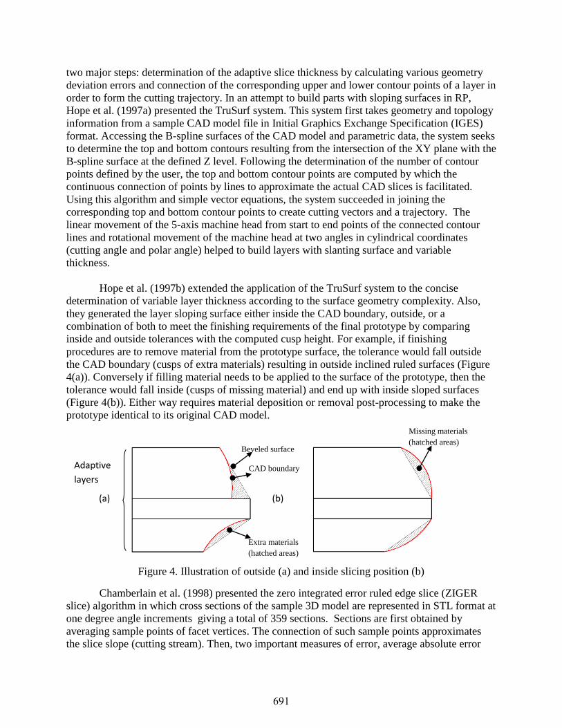
Hope et al. (1997b) extended the application of the TruSurf system to the concise
determination of variable layer thickness according to the surface geometry complexity. Also,
they generated the layer sloping surface either inside the CAD boundary, outside, or a
combination of both to meet the finishing requirements of the final prototype by comparing
inside and outside tolerances with the computed cusp height. For example, if finishing
procedures are to remove material from the prototype surface, the tolerance would fall outside
the CAD boundary (cusps of extra materials) resulting in outside inclined ruled surfaces (Figure
4(a)). Conversely if filling material needs to be applied to the surface of the prototype, then the
tolerance would fall inside (cusps of missing material) and end up with inside sloped surfaces
(Figure 4(b)). Either way requires material deposition or removal post-processing to make the
prototype identical to its original CAD model.
Figure 4. Illustration of outside (a) and inside slicing position (b)
Chamberlain et al. (1998) presented the zero integrated error ruled edge slice (ZIGER
slice) algorithm in which cross sections of the sample 3D model are represented in STL format at
one degree angle increments giving a total of 359 sections. Sections are first obtained by
averaging sample points of facet vertices. The connection of such sample points approximates
the slice slope (cutting stream). Then, two important measures of error, average absolute error
CAD boundary
(a) (b)
Beveled surface
Extra materials
(hatched areas)
Missing materials
(hatched areas)
Adaptive
layers
691

and maximum absolute error, contribute to the determination of adaptive thickness slicing. In
fact, the above errors were the negative and positive areas emerging between the CAD surface
and approximate slope surface (Figure 5).
Figure 5. A view of ZIGER slice
Utilizing STL file format, Taylor et al. (2001) computed the intersection of a CAD model
represented in STL format with the Z plane at a specified Z value to create a chain of line
segments forming the closed-loop or contour. The start and end points of these line segments are
swept half the layer thickness above and below the cutting plane to form rectangles in the
vertical or slanting depending on the angle of the cutting vector. These rectangles based on the
start and end points of a line segment on the created contour and the cutting angle correspond to
discreet cutter locations during machining of that contour (Figure 6).
Figure 6. An illustration of cutting trajectory formation.
In conjunction with adaptive ruled layers, Koc and Lee (2002) took into account the
generation of ruled surfaces obtained by joining the corresponding top and bottom contour points
of an adaptive layer. They concentrated on developing accurate connections of those points such
that any twisted surfaces, surface approximation errors, and incorrect contour point joins would
be avoided. The algorithm worked well for the connection of top and bottom contour points that
were different in number and lent itself to the creation of ruled lines and surfaces, hence easing
the generation of machine cutting paths suitable for 5-axis RP (Figure 7).
Negative error
Positive error
Approximate
beveled surface
CAD boundary Adaptive
layers
Swept half the above
cutting plane
Swept half the below
cutting plane
Trigger points
692

Figure 7. Forming the ruled surface.
In another attempt to form ruled surfaces between the contours of an adaptive slice,
Gupta et al. (2004) proposed an algorithm to stitch together unequal optimized numbers of top
and bottom contour points to obtain acceptable ruled lines, thereby generating well-shaped
sloping surfaces and conforming closely to the part surface boundary. Besides computing the
optimum number of contour points and developing an adaptive slicing approach, they also
provided a solution to the problem of cutting triangle patches that emerged from the multiple
connection of one contour point with different points in its corresponding top or bottom contour.
Yoo and Walczyk (2005) developed an advanced cutting trajectory algorithm for the profiled
edge laminate (PEL) rapid tooling (RT) process (the process of the fabrication of large-scale dies
and molds). Instead of slicing a CAD model represented by STL format, they directly performed
the slicing process through SolidWorks API. A method for discretization of continuous profiles
(i.e. the combination of arcs, splines, parabolas, and ellipsoids) of the CAD model has been
developed. To stitch the obtained contour points appearing in front and back profiles for the
purpose of accurate PEL surface reconstruction and the creation of optimized cutting vectors, an
adaptive surface reconstruction algorithm consisting of Delaunay triangulation and a new
complementary stitching algorithm were successfully implemented. The PEL technique is
believed to be suitable for thick-layer rapid tooling that is suitable for 5-axis AWJ cutting
machines leading to high quality prototypes.
In a nutshell, despite the fact that many endeavors have been carried out in the scope of
beveled-edge slicing, no research has been reported to address curved-form lamination for
intricate beveled surfaces. Therefore, the possibility of generating accurate machine path
enabling curved-form sloped-edge lamination compatible with 5-axis abrasive waterjet (AWJ)
cutters will enable fabrication of functional parts from fully dense sheets with geometrical
characteristics very near to their original CAD models.
Therefore, the main objective of the present research is to generate sloping surfaces on
the edge of an adaptive layer. The resulting surface has much less geometry deviation error and
closely fits its CAD model boundary. The proposed system works in the following order: It
takes in topology and geometry information from previously generated adaptive layers (Hayasi,
Asiabanpour; 2011). Then, the thickness of an adaptive layer and the bottom and top contours of
adjacent layers are fed into the proposed algorithm in the form of the continuous connection of
vectors and their cutting vector with the facet normal for the creation of curved-form sloping
surfaces. Following curved-form adaptive slicing, a customized machine path and CNC code
Top contour
Bottom contour
Ruled surface
693
compatible with 5-axis abrasive waterject cutters will be generated for any user-defined sheet
thicknesses.
The remainder of the paper is organized as follows: Section 2 briefly introduces the
concept of rapid tooling (RT) and a new RT process named fully dense freeform fabrication
(FDFF) with particular focus on metallic functional parts. In line with the quality improvement
of the parts cut by the 5-axis abrasive waterjet, details of the new sloped-edge adaptive slicing
system are presented in Section 3. Section 4 illustrates customized machine path and CNC-code
generation which is consistent with current slicing systems and compatible with 5-axis abrasive
waterjets without requiring machine setup modifications. Section 5 deals with implementation of
the proposed system. Results achieved by application of the developed software on complex 3D
CAD models are presented in Section 6. Finally, future work and conclusions are discussed in
section 7.
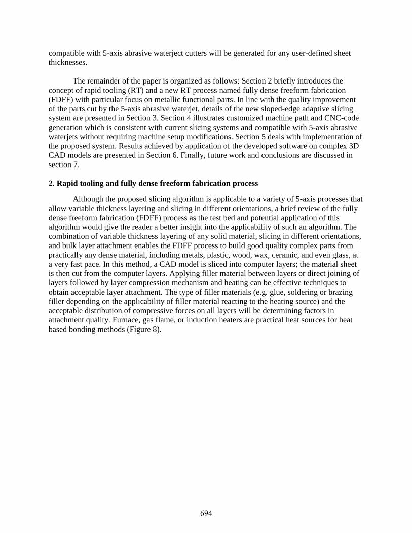
2. Rapid tooling and fully dense freeform fabrication process
Although the proposed slicing algorithm is applicable to a variety of 5-axis processes that
allow variable thickness layering and slicing in different orientations, a brief review of the fully
dense freeform fabrication (FDFF) process as the test bed and potential application of this
algorithm would give the reader a better insight into the applicability of such an algorithm. The
combination of variable thickness layering of any solid material, slicing in different orientations,
and bulk layer attachment enables the FDFF process to build good quality complex parts from
practically any dense material, including metals, plastic, wood, wax, ceramic, and even glass, at
a very fast pace. In this method, a CAD model is sliced into computer layers; the material sheet
is then cut from the computer layers. Applying filler material between layers or direct joining of
layers followed by layer compression mechanism and heating can be effective techniques to
obtain acceptable layer attachment. The type of filler materials (e.g. glue, soldering or brazing
filler depending on the applicability of filler material reacting to the heating source) and the
acceptable distribution of compressive forces on all layers will be determining factors in
attachment quality. Furnace, gas flame, or induction heaters are practical heat sources for heat
based bonding methods (Figure 8).
694
Figure 8. Visualization of the sequences of the FDFF process
Different aspects of the rapid tooling (RT) approaches have been addressed by many researchers
such as Nakagawa and Kunieda (1984), Vouzelaud et al. (1992), Glozer and Bervick (1992),
Walczyk and Hardt (1996), Bryden et al. (2001), Gibbons et al., (2003), Himmer et al (2003),
Perchtl et al. (2005), and Glen et al., 2011.
3. Curved-form adaptive slicing
3-1- Adaptive slicing
The input to curved-form adaptive slicing algorithms is an adaptive slice which carries a
limited number of thin layers in order to be assigned an available thick layer. In adaptive slicing
the CAD model is initially sliced at the maximum available thickness. Adaptive slicing then
applies some specific tolerances to decide whether or not to break the thicker slab down into
thinner ones. From this some basic information of a typical adaptive slice such as layer thickness
and contour points of the top and the bottom slices of the associated layer are generated. The
present system requires topology and geometry information of all thin layers that shape an
adaptive slice with the desired thickness (Hayasi and Asiabanpour, 2011).
3-2- Data structure formation for contours
For each layer whether thin (consisting of a bottom and top slice) or thick (encompassing
more than two slices), an array of a specific data structure containing the required information
for the slices (e.g. the internal and external closed-loop of each slice, the co-planar vectors of
each contour, a surface identity assigned to each contour vector, and facet normal vector
belonging to each contour vector) will be created. The contours are obtained by the continued
connection of vectors or line segments resulting from the intersection of the XY-plane with
selected facets at the defined Z level in counter clock-wise (CCW) fashion. Since a contour
vector or line segment is the result of connecting two points laid upon the edges of a facet, the
695
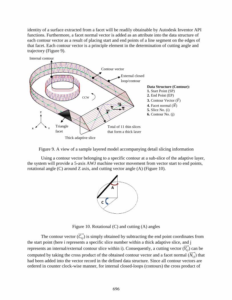
identity of a surface extracted from a facet will be readily obtainable by Autodesk Inventor API
functions. Furthermore, a facet normal vector is added as an attribute into the data structure of
each contour vector as a result of placing start and end points of a line segment on the edges of
that facet. Each contour vector is a principle element in the determination of cutting angle and
trajectory (Figure 9).
Figure 9. A view of a sample layered model accompanying detail slicing information
Using a contour vector belonging to a specific contour at a sub-slice of the adaptive layer,
the system will provide a 5-axis AWJ machine vector movement from vector start to end points,
rotational angle (C) around Z axis, and cutting vector angle (A) (Figure 10).
Figure 10. Rotational (C) and cutting (A) angles
The contour vector ( ) is simply obtained by subtracting the end point coordinates from
the start point (here i represents a specific slice number within a thick adaptive slice, and j
represents an internal/external contour slice within i). Consequently, a cutting vector ( ) can be
computed by taking the cross product of the obtained contour vector and a facet normal ( ) that
had been added into the vector record in the defined data structure. Since all contour vectors are
ordered in counter clock-wise manner, for internal closed-loops (contours) the cross product of
Contour vector
External closed
loop/contour
Internal contour
CCW
Thick adaptive slice
Total of 11 thin slices
that form a thick layer
Triangle
facet
Data Structure (Contour):
1. Start Point (SP)
2. End Point (EP)
3. Contour Vector (�� )
4. Facet normal (�� ) 5. Slice No. (i)
6. Contour No. (j)
A
C
696
vectors must be given by
and by the opposite (
) for external
contours in order to lead the pick of the cutting vector in the direction of the cutting stream.
Following calculation of the above vectors, the two rotational and cutting angles are obtained as
follows:
Cutting Vector angle:
‖ ‖‖ ‖
Rotational angle:
‖ ‖‖ ‖
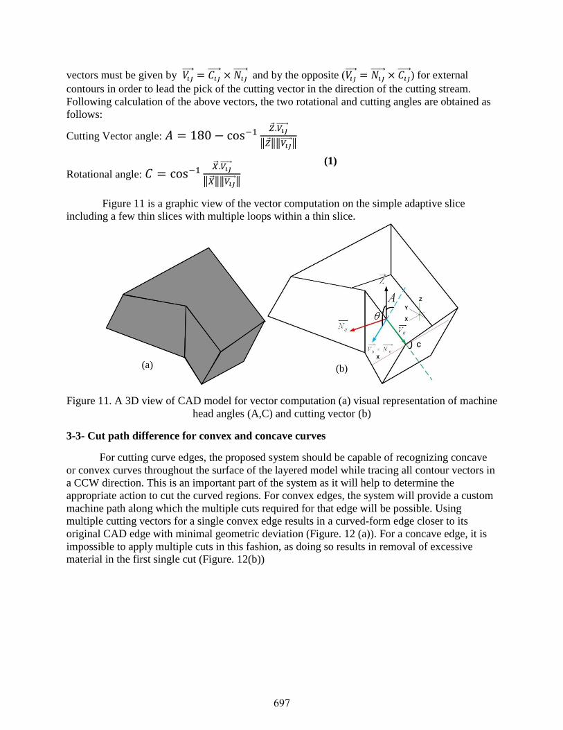
Figure 11 is a graphic view of the vector computation on the simple adaptive slice
including a few thin slices with multiple loops within a thin slice.
Figure 11. A 3D view of CAD model for vector computation (a) visual representation of machine
head angles (A,C) and cutting vector (b)
3-3- Cut path difference for convex and concave curves
For cutting curve edges, the proposed system should be capable of recognizing concave
or convex curves throughout the surface of the layered model while tracing all contour vectors in
a CCW direction. This is an important part of the system as it will help to determine the
appropriate action to cut the curved regions. For convex edges, the system will provide a custom
machine path along which the multiple cuts required for that edge will be possible. Using
multiple cutting vectors for a single convex edge results in a curved-form edge closer to its
original CAD edge with minimal geometric deviation (Figure. 12 (a)). For a concave edge, it is
impossible to apply multiple cuts in this fashion, as doing so results in removal of excessive
material in the first single cut (Figure. 12(b))
(1)
(a) (b)
697
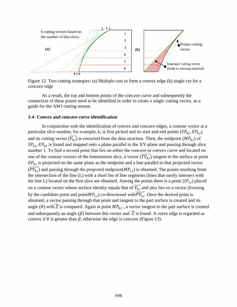
Figure 12. Two cutting strategies: (a) Multiple cuts to form a convex edge (b) single cut for a
concave edge
As a result, the top and bottom points of the concave curve and subsequently the
connection of these points need to be identified in order to create a single cutting vector, as a
guide for the AWJ cutting stream.
3-4- Convex and concave curve identification
In conjunction with the identification of convex and concave edges, a contour vector at a
particular slice number, for example, k, is first picked and its start and end points ( )
and its cutting vector ( ) is extracted from the data structure. Then, the midpoint ( ) of
is found and mapped onto a plane parallel to the XY-plane and passing through slice
number 1. To find a second point that lies on either the concave or convex curve and located on
one of the contour vectors of the bottommost slice, a vector ( ) tangent to the surface at point
is projected on the same plane as the midpoint and a line parallel to that projected vector
( ) and passing through the projected midpoint( ) is obtained. The points resulting from
the intersection of the line (L) with a short list of line segments (lines that surely intersect with
the line L) located on the first slice are obtained. Among the points there is a point ( ) placed
on a contour vector whose surface identity equals that of and also lies on a vector (forming
by the candidate point and point ) co-directional with . Once the desired point is
obtained, a vector passing through that point and tangent to the part surface is created and its
angle ( ) with is computed. Again at point , a vector tangent to the part surface is created
and subsequently an angle ( ) between this vector and is found. A curve edge is regarded as
convex if is greater than otherwise the edge is concave (Figure 13).
Proper cutting
vector
Improper cutting vector
(leads to missing material)
6 cutting vectors based on
the number of thin slices
4
5
6
(a) (b)
1
2
3
4
5
5 6
1
3
2
698

Figure 13. Graphical representation of how a convex edge is identified
3-5- Curved-form adaptive slicing main algorithm
Once the adaptive slicing from the bottom to top of the CAD model is accurately
accomplished, an external contour for each adaptive layer containing a number of thin slices is
selected from among contours in the top slice of the layer. The initial vector in the chain of the
vectors is obtained from the data structure of the contour vectors belonging to the selected
contour and the possibility of being convex or concave at this point is evaluated using the
method explained above. With regard to concave curves a straight sloping surface is formed by
mapping the start and end points of the selected vector onto a plane parallel to the XY-plane and
accommodating the contours of the bottom slice. Then two lines passing through the mapped
points and parallel with the projected cutting vector of the top contour vector are drawn. The
intersection of the lines with the corresponding line segments (contour vectors) on the bottom
slice results in two additional points. Eventually, the desired beveled surface, which is created by
the connection of those four points, would be a useful tool for both visual simulations of the
curved-form cutting and as a source to generate 5-axis AWJ cutter machine trajectories (Figure
14(a)).
Unlike for concave curves the system is required to provide multiple slanting surfaces
such that its output conforms to the curvature of convex region. With the assumption that the
curvature of the part surface at the initial selected contour vector is found to be convex using the
method explained, two lines passing through the start and end point of that vector and parallel to
the cutting vector at this location are created. The two lines then intersect with a plane parallel to
the XY-plane at a Z-level where the bottom slice is located (Figure 14(b)). The points resulting
from the line-plane intersection are simply obtained by the following equation 2.
Line equation:
, ,
By setting
then
(2)
699

Figure 14. Illustration of a single cutting stream for concave edge (a) and multiple cutting
streams for convex edge (b) formed by a number of thin slices
The first slanting surface formed by the connection of the four points is retained in
computer memory for further use in machine path generation. To complete beveled surface
formation on the top slice, the system seeks to trace all the vectors within either external or
internal loops of the slice and apply the above described algorithm. For the remainder of the thin
slices, if the curvature of a part surface at a certain vector is found to be concave, the surface
formation must be neglected based on the rule defined for such concave curves (i.e. single sloped
cutting surface on concave edges). An overview of the developed algorithm presented as a
flowchart is shown in Figure 15.
(a) (b)
700
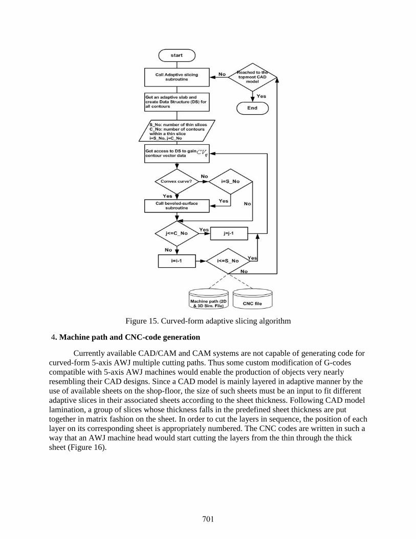
Figure 15. Curved-form adaptive slicing algorithm
4. Machine path and CNC-code generation
Currently available CAD/CAM and CAM systems are not capable of generating code for
curved-form 5-axis AWJ multiple cutting paths. Thus some custom modification of G-codes
compatible with 5-axis AWJ machines would enable the production of objects very nearly
resembling their CAD designs. Since a CAD model is mainly layered in adaptive manner by the
use of available sheets on the shop-floor, the size of such sheets must be an input to fit different
adaptive slices in their associated sheets according to the sheet thickness. Following CAD model
lamination, a group of slices whose thickness falls in the predefined sheet thickness are put
together in matrix fashion on the sheet. In order to cut the layers in sequence, the position of each
layer on its corresponding sheet is appropriately numbered. The CNC codes are written in such a
way that an AWJ machine head would start cutting the layers from the thin through the thick
sheet (Figure 16).
701
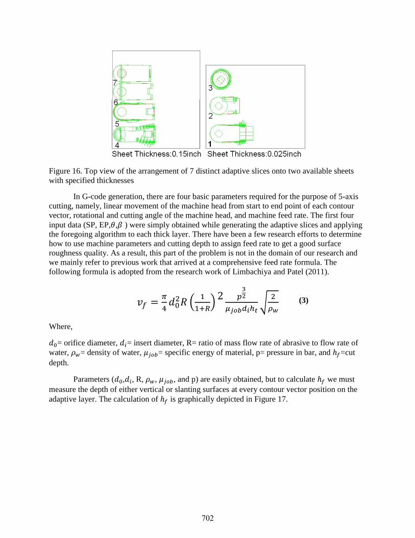
Figure 16. Top view of the arrangement of 7 distinct adaptive slices onto two available sheets
with specified thicknesses
In G-code generation, there are four basic parameters required for the purpose of 5-axis
cutting, namely, linear movement of the machine head from start to end point of each contour
vector, rotational and cutting angle of the machine head, and machine feed rate. The first four
input data (SP, EP, , ) were simply obtained while generating the adaptive slices and applying
the foregoing algorithm to each thick layer. There have been a few research efforts to determine
how to use machine parameters and cutting depth to assign feed rate to get a good surface
roughness quality. As a result, this part of the problem is not in the domain of our research and
we mainly refer to previous work that arrived at a comprehensive feed rate formula. The
following formula is adopted from the research work of Limbachiya and Patel (2011).
(
)
√
Where,
= orifice diameter, = insert diameter, R= ratio of mass flow rate of abrasive to flow rate of
water, = density of water, = specific energy of material, p= pressure in bar, and =cut
depth.
Parameters ( , , R, , , and p) are easily obtained, but to calculate we must
measure the depth of either vertical or slanting surfaces at every contour vector position on the
adaptive layer. The calculation of is graphically depicted in Figure 17.
(3)
702

Figure 17. The explicit computation of in the projected view of a sample adaptive slice
5. System implementation
The algorithm was implemented using Visual Basic for Application (VBA) and Autodesk
Inventor mechanical design software. Autodesk Inventor API functions were used to gain direct
access to topology and geometry information of any complex CAD model. A user interface form
facilitates data entries (i.e., slice direction in either X, Y, or Z directions, various sheet
thicknesses, allowable errors for boundary area deviation, triangle area, number of available
sheets, sheets thickness, and the width and length of the sheets). Figure 18 illustrates the user
interface form for triple slicing approaches that was developed in response to a user request.
Even though the generated 5-axis AWJ machine codes are saved in one text file, the software
output can be obtained layer by layer in the 2D and 3D versions. In the 2D version, the generated
layers containing line segments and sloping surfaces are grouped according to their sheet
thickness and spread on the sheet rectangle surfaces in matrix form followed by numbering each
adaptive slice. In contrast, in the 3D version all layers along with their cutting surfaces in their
own thickness are stacked together in the build direction to form an approximate real 3D solid
model for better visualization of the final physical part being fabricated by the FDFF process.
703

Figure 18. The user interface form.
6. System results, verification, and validation
The implemented system was successfully tested for slicing a variety of models with
diverse types of surfaces (i.e., flat, convex, and concave), different slicing direction, and different
number of sheets with different thicknesses. The following example along with different stages
of the curved form adaptive slicing is presented below:
The entries for model were: sheet thicknesses and sizes T1: 0.1 in, L1: 20 in, W1: 15 in,
T2: 0.25 in, L2: 15 in, W2: 30 in, and Cut direction: Z (Figure 19)
704

Figure 19. (a) 3D CAD model and (b-d) 3D and side view of curved-form adaptive slicing
7- Conclusion
In this article a new curved-form adaptive slicing method is presented. In this method,
multiple cuts of the edge boundary of each adaptive layer with variable cutting vectors angles
conform well to the CAD model curved surfaces. The results showed that the staircase effect, a
common error in adaptive slicing, existing on either concave or convex edges has been
significantly reduced utilizing this method. The proposed system is compatible with 5-axis
abrasive waterjet machines. This system has been successfully tested on several models. The
main application of the proposed system is in the FDFF process. Metallic sheets with variety of
predefined thicknesses can be cut with angular direction by a 5-axis AWJ machine and according
to the tool path generated by the proposed system. Then, layers are aligned and bonded in the
FDFF process. The bonding process is typically by the induction heater and by using the brazing
materials. Therefore, the mechanical properties of the fabricated parts are good enough to be
used as the functional parts. The FDFF process has been extensively used and tested for the parts
cut by a 2 axis AWJ machine. The future of this research is the test of the FDFF process for the
parts cut by a 5 axis AWJ machine, subject to purchase/access.
References
Asiabanpour, B., & Khoshnevis, B. (2004). Machine path generation for the SIS process.
Robotics and Computer-Integrated Manufacturing, 20, 167–175.
Bryden, B.G., Wimpenny, D.I., & Pashby I.R. (2001). Manufacturing Production tooling using
metal laminations. Rapid Prototyping Journal, 7(1):52-59.
705

Chamberlain, P.B., Van Rossendaal, M.D., & Thomas, C.L. (1998). Variable thickness ruled
edge slice generation and three-dimensional graphical error visualization. Proceedings of
the Solid Free Fabrication Symposium, August (1998), 311–318.
Gibbons, G.J., Hansell, R.G., Norwood, A.J., & Dickens P.M. (2003). Rapid laminated die-cast
tooling. Rapid Prototyping Journal, 23(4):372-381.
Glen, T.C., Loerwald, M., Hayasi, M., & Asiabanpour, B. (2011). Layer Alignment and
Lamination for the Fully Dense Freeform Fabrication (FDFF) Process. 22nd International
Solid Freeform Fabrication (SFF) Symposium, Austin, TX.
Glozer, G. R., & Brevick, J. R. (1992). Laminate tooling for injection molding. Proceedings of
the Institution of Mechanical Engineers, Part B: Journal of Engineering Manufacture,
207, 9-15.
Gupta, T., Chandila, P.K., Tripathi, P., & Roy Choudhury, A. (2004). Direct slicing with
optimum number of contour points. International Journal of CAD/CAM, 4(1):1-2.
Hayasi, M., & Asiabanpour, B. (2011). “Adaptive Direct Slicing and Machine Path Generation
for the Fully Dense Freeform Fabrication (FDFF) Process with the Variable Layers”,
22nd International Solid Freeform Fabrication (SFF) Symposium, Austin, TX, 2011.
Himmer, T., Techel, A., Nowotny, S., & Beyer, e. (2003). Recent developments in metal
laminated tooling by multiple laser processing. Rapid Prototyping Journal, 9(1):24-29.
Hope, R. L., Jacobs, P.A., & Roth, R.N. (1997). Rapid prototyping with sloping surfaces. 1.
Rapid Prototyping Journal, 3(1): 12-19.
Hope, R. L., Roth, R. N., & Jacobs, P.A. (1997). Adaptive slicing with sloping layer surfaces. 2.
Rapid Prototyping Journal, 3(3): 89-98.
Koc, B., & Lee, Y.S. (2002). Adaptive Ruled Layers Approximation of STL Models and
Multiaxis Machining Applications for Rapid Prototyping. Journal of Manufacturing
Systems, 21(3):153-166.
Limbachiya, V.J., & Patel, D.M. (2011). An Investigation of Different Material on Abrasive
Water jet Machine. International Journal of Engineering Science and Technology
(IJEST), 3(7):5940-5945.
Nakagawa, T., & Kunieda, M. (1984). Manufacturing of laminated deep drawing dies by laser
beam cutting. Advanced Technology of Plasticity, Vol. 1.
Taylor, J.B., Cormier, D.R., Joshi, s. & Venkataraman, V. (2001). Contoured edge slice
generation in rapid prototyping via 5-axis machining. Robotics and Computer Integrated
Manufacturing, 17:13-18.
Vouzelaud, F.A., Bagchi, A., & Sferro, P.F. (1992). Adaptive laminated machining for prototype
dies and molds: part I and II. Proceedings of the 3rd Symposium in Solid Freeform
Fabrication, Austin, TX.
Vouzelaud, T., & Bagchi, A. (1995). An adaptive lamina generation for shape dependent process
control and/or object decomposition. Patent number: 5,432,704.
Walczyk, D. Hardt. (1996). Recent developments in profiled-edge lamination dies for sheet
metal forming. Proceedings of the Seventh Solid Freeform Fabrication Symposium,
Austin, TX.
Yoo, S., & Walczyk, D. (2005). An advanced cutting trajectory algorithm for laminated tooling.
Rapid Prototyping Journal, 11:199-213.
706