Configuring Dynamic DNS
12
Advanced Configuration 8-1 v1.0, February 2008 Chapter 8 Advanced Configuration This chapter describes how to configure the advanced features of your ProSafe 802.11g Wireless VPN Firewall FVG318. Configuring Dynamic DNS If your network has a permanently assigned IP address, you can register a domain name and have that name linked with your IP address by public Domain Name Servers (DNS). However, if your Internet account uses a dynamically assigned IP address, you will not know in advance what your IP address will be, and the address can change frequently. In this case, you can use a commercial dynamic DNS service, which will allow you to register your domain to their IP address, and will forward traffic directed to your domain to your frequently-changing IP address. The firewall contains a client that can connect to a dynamic DNS service provider. To use this feature, you must select a service provider and obtain an account with them. After you have configured your account information in the firewall, whenever your ISP-assigned IP address changes, your firewall will automatically contact your dynamic DNS service provider, log in to your account, and register your new IP address. 1. Log in to the firewall at its default LAN address of http://192.168.0.1 with its default user name of admin, default password of password, or using whatever password and LAN address you have chosen for the firewall. 2. Select Network Configuration > Dynamic DNS on the main menu of the browser interface. The Dynamic DNS screen will display. 3. Access the Web site of one of the dynamic DNS service providers whose names appear in the menu, and register for an account. For example, for dyndns.org, go to www.dyndns.org. 4. Select the name of your dynamic DNS Service Provider. 5. Type the host and domain name that your dynamic DNS provider gave you. This will look like a URL, such as myName.dyndns.org. 6. Type the user name for your dynamic DNS account. 7. Type the password (or key) for your dynamic DNS account.
Transcript of Configuring Dynamic DNS
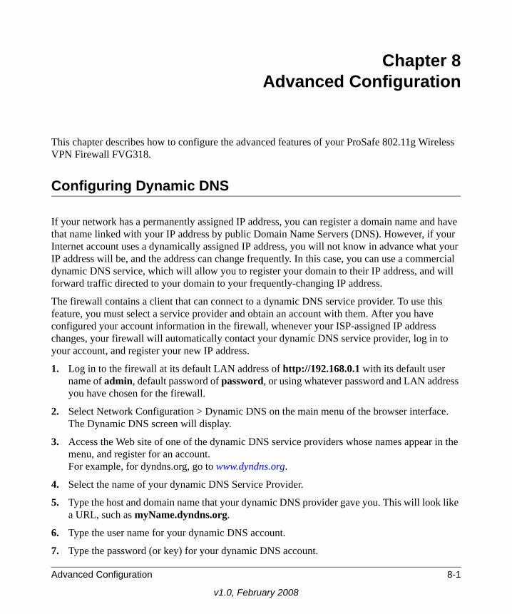
Chapter 8Advanced Configuration
This chapter describes how to configure the advanced features of your ProSafe 802.11g Wireless VPN Firewall FVG318.
Configuring Dynamic DNS
If your network has a permanently assigned IP address, you can register a domain name and have that name linked with your IP address by public Domain Name Servers (DNS). However, if your Internet account uses a dynamically assigned IP address, you will not know in advance what your IP address will be, and the address can change frequently. In this case, you can use a commercial dynamic DNS service, which will allow you to register your domain to their IP address, and will forward traffic directed to your domain to your frequently-changing IP address.
The firewall contains a client that can connect to a dynamic DNS service provider. To use this feature, you must select a service provider and obtain an account with them. After you have configured your account information in the firewall, whenever your ISP-assigned IP address changes, your firewall will automatically contact your dynamic DNS service provider, log in to your account, and register your new IP address.
1. Log in to the firewall at its default LAN address of http://192.168.0.1 with its default user name of admin, default password of password, or using whatever password and LAN address you have chosen for the firewall.
2. Select Network Configuration > Dynamic DNS on the main menu of the browser interface. The Dynamic DNS screen will display.
3. Access the Web site of one of the dynamic DNS service providers whose names appear in the menu, and register for an account.For example, for dyndns.org, go to www.dyndns.org.
4. Select the name of your dynamic DNS Service Provider.
5. Type the host and domain name that your dynamic DNS provider gave you. This will look like a URL, such as myName.dyndns.org.
6. Type the user name for your dynamic DNS account.
7. Type the password (or key) for your dynamic DNS account.
Advanced Configuration 8-1
v1.0, February 2008

ProSafe 802.11g Wireless VPN Firewall FVG318 Reference Manual
8. If your dynamic DNS provider allows the use of wildcards in resolving your URL, you may select the Use wildcards check box to activate this feature. For example, the wildcard feature will cause *.yourhost.dyndns.org to be aliased to the same IP address as yourhost.dyndns.org
9. Click Apply to save your configuration.
Using the LAN IP Setup Options
The LAN IP Setup menu allows configuration of LAN IP services such as DHCP. Select Network Configuration > LAN Setup to view the screen shown below
Configuring LAN TCP/IP Setup ParametersThe firewall is shipped preconfigured to use private IP addresses on the LAN side, and to act as a DHCP server. The firewall’s default LAN IP configuration is:
• LAN IP addresses: 192.168.0.1• Subnet mask: 255.255.255.0
Note: If your ISP assigns a private WAN IP address such as 192.168.x.x or 10.x.x.x, the dynamic DNS service will not work because private addresses will not be routed on the Internet.
Figure 8-1
8-2 Advanced Configuration
v1.0, February 2008

ProSafe 802.11g Wireless VPN Firewall FVG318 Reference Manual
These addresses are part of the IETF-designated private address range for use in private networks, and should be suitable in most applications. If your network has a requirement to use a different IP addressing scheme, you can make those changes in this menu.
The LAN IP parameters are:
• IP Address. This is the LAN IP address of the firewall.
• IP Subnet Mask. This is the LAN Subnet Mask of the firewall. Combined with the IP address, the IP Subnet Mask allows a device to know which other addresses are local to it, and which must be reached through a gateway or firewall.
Using the Firewall as a DHCP serverBy default, the firewall functions as a DHCP (Dynamic Host Configuration Protocol) server, allowing it to assign IP, DNS server, and default gateway addresses to all computers connected to the firewall’s LAN. The assigned default gateway address is the LAN address of the firewall. IP addresses will be assigned to the attached PCs from a pool of addresses specified in this menu. Each pool address is tested before it is assigned to avoid duplicate addresses on the LAN.
For most applications, the default DHCP and TCP/IP settings of the firewall are satisfactory. See “Preparing a Computer for Network Access” in Appendix B, “Related Documents” for an explanation of DHCP and information about how to assign IP addresses for your network.
If another device on your network will be the DHCP server, or if you will manually configure the network settings of all of your computers, clear the Use router as DHCP server check box. Otherwise, leave it checked.
To specify the pool of IP addresses to be assigned, set the Starting IP Address and Ending IP Address. These addresses should be part of the same IP address subnet as the firewall’s LAN IP address. Using the default addressing scheme, you should define a range between 192.168.0.2 and 192.168.0.100, although you may wish to save part of the range for devices with fixed addresses.
The firewall will deliver the following parameters to any LAN device that requests DHCP:
• An IP address from the range you have defined
• Subnet mask
• Gateway IP address (the firewall’s LAN IP address)
Note: If you change the LAN IP address of the firewall while connected through the browser, you will be disconnected. You must then open a new connection to the new IP address and log in again.
Advanced Configuration 8-3
v1.0, February 2008

ProSafe 802.11g Wireless VPN Firewall FVG318 Reference Manual
• Primary DNS server (if you entered a primary DNS address in the WAN Settings menu; otherwise, the firewall’s LAN IP address)
• Secondary DNS server (if you entered a secondary DNS address in the WAN Settings menu
Using Address ReservationWhen you specify a reserved IP address for a PC on the LAN, that PC will always receive the same IP address each time it accesses the firewall’s DHCP server. Reserved IP addresses should be assigned to servers that require permanent IP settings.
To reserve an IP address:
1. Click the LAN Groups tab.
2. In the Add Known PCs and Devices section, enter a name for the PC in the Name field so that it is easily recognizable.
3. From the IP Address Type pull-down menu, select Reserved (DHCP Client).
4. Type the IP address to assign to the PC or server.(Choose an IP address from the firewall’s LAN subnet, such as 192.168.0.X.)
5. Type the MAC Address of the PC or server.
6. Click Apply to enter the reserved address into the table.
To edit or delete a reserved address entry:
1. Click Edit next to the reserved address you want to edit or delete and edit the fields on the Edit Known PC and Device screen. Click Apply.
2. Select the checkbox adjacent to the IP address you want to delete and click Delete.
Note: The reserved address will not be assigned until the next time the PC contacts the firewall’s DHCP server. Reboot the PC or access its IP configuration and force a DHCP release and renew.
8-4 Advanced Configuration
v1.0, February 2008
ProSafe 802.11g Wireless VPN Firewall FVG318 Reference Manual
Configuring Static Routes
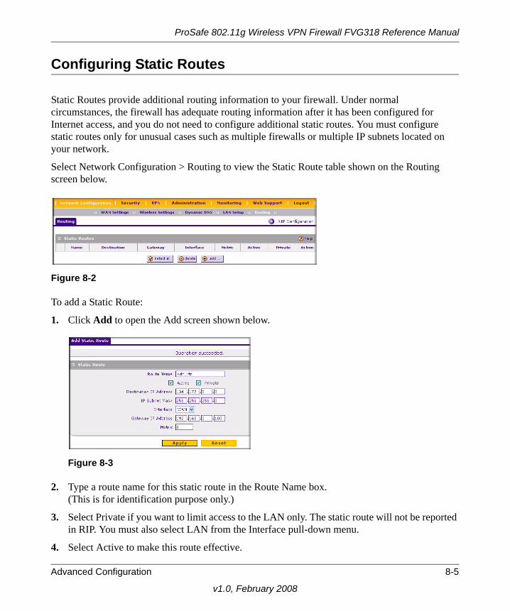
Static Routes provide additional routing information to your firewall. Under normal circumstances, the firewall has adequate routing information after it has been configured for Internet access, and you do not need to configure additional static routes. You must configure static routes only for unusual cases such as multiple firewalls or multiple IP subnets located on your network.
Select Network Configuration > Routing to view the Static Route table shown on the Routing screen below.
To add a Static Route:
1. Click Add to open the Add screen shown below.
2. Type a route name for this static route in the Route Name box.(This is for identification purpose only.)
3. Select Private if you want to limit access to the LAN only. The static route will not be reported in RIP. You must also select LAN from the Interface pull-down menu.
4. Select Active to make this route effective.
Figure 8-2
Figure 8-3
Advanced Configuration 8-5
v1.0, February 2008

ProSafe 802.11g Wireless VPN Firewall FVG318 Reference Manual
5. Type the Destination IP Address of the final destination.
6. Type the IP Subnet Mask for this destination.If the destination is a single host, type 255.255.255.255.
7. Type the Gateway IP Address, which must be a firewall on the same LAN segment as the firewall.
8. Type a number between 1 and 15 as the Metric value. This represents the number of firewalls between your network and the destination. Usually, a setting of 2 or 3 works, but if this is a direct connection, set it to 1.
9. Click Apply to have the static route entered into the table as shown below.
To edit the static route entry, click Edit.
Configuring RIP.RIP (Routing Information Protocol, RFC 2453) is an Interior Gateway Protocol (IGP) that is commonly used in internal networks. It allows a router to exchange routing information automatically with other routers, and allows it to dynamically adjust its routing tables and adapt to changes in the network.
To enable RIP:
1. Click the RIP Configuration link on the Routing screen (shown in Figure 8-4 above).The RIP Configuration screen will display
2. Select the RIP Direction.The RIP Direction selection controls how the firewall sends and receives RIP packets. Both is the default.
– When set to Both or Out Only, the firewall broadcasts its routing table periodically.
Figure 8-4
Note: RIP is disabled by default.
8-6 Advanced Configuration
v1.0, February 2008
ProSafe 802.11g Wireless VPN Firewall FVG318 Reference Manual
– When set to Both or In Only, it incorporates the RIP information that it receives.
– When set to None, it will not send any RIP packets and ignores any RIP packets received.
3. Enable the RIP Version. This controls the format and the broadcasting method of the RIP packets that the firewall sends. (It recognizes both formats when receiving.)
– RIP-1 is universally supported. RIP-1 is probably adequate for most networks, unless you have an unusual network setup.
– RIP-2 carries more information.
– RIP-2B uses subnet broadcasting.RIP-2B broadcasts data in the entire subnet.
– RIP-2M sends data to multicast addresses.
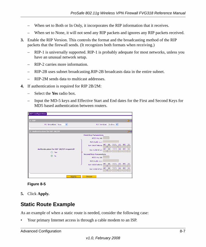
4. If authentication is required for RIP 2B/2M:
– Select the Yes radio box.
– Input the MD-5 keys and Effective Start and End dates for the First and Second Keys for MD5 based authentication between routers.
5. Click Apply.
Static Route ExampleAs an example of when a static route is needed, consider the following case:
• Your primary Internet access is through a cable modem to an ISP.
Figure 8-5
Advanced Configuration 8-7
v1.0, February 2008

ProSafe 802.11g Wireless VPN Firewall FVG318 Reference Manual
• You have an ISDN firewall on your home network for connecting to the company where you are employed. This firewall’s address on your LAN is 192.168.0.100.
• Your company’s network is 134.177.0.0.
When you first configured your firewall, two implicit static routes were created. A default route was created with your ISP as the gateway, and a second static route was created to your local network for all 192.168.0.x addresses. With this configuration, if you attempt to access a device on the 134.177.0.0 network, your firewall will forward your request to the ISP. The ISP forwards your request to the company where you are employed, and the request will likely be denied by the company’s firewall.
In this case you must define a static route, telling your firewall that 134.177.0.0 should be accessed through the ISDN firewall at 192.168.0.100. The static route would look like Figure 8-4.
In this example:
• The Destination IP Address and IP Subnet Mask fields specify that this static route applies to all 134.177.x.x addresses.
• The Gateway IP Address fields specifies that all traffic for these addresses should be forwarded to the ISDN firewall at 192.168.0.100.
• A Metric value of 1 will work since the ISDN firewall is on the LAN.
• Private is selected only as a precautionary security measure in case RIP is activated.
Enabling Remote Management Access
Using the Remote Management page, you can allow a user or users on the Internet to configure, upgrade and check the status of your FVG318 VPN firewall.
To configure your firewall for Remote Management:
1. Select Administration > Remote Management from the main menu. The Remote Management screen will display.
Note: Be sure to change the firewall’s default configuration password to a very secure password. The ideal password should contain no dictionary words from any language, and should be a mixture of letters (both upper and lower case), numbers, and symbols. Your password can be up to 30 characters.
8-8 Advanced Configuration
v1.0, February 2008

ProSafe 802.11g Wireless VPN Firewall FVG318 Reference Manual
2. Select the Yes radio box for Allow Remote Management.
• Specify what external addresses will be allowed to access the firewall’s remote management.
• To allow access from any IP address on the Internet, select Everyone.
• To allow access from a range of IP addresses on the Internet, select IP address range.Enter a beginning and ending IP address to define the allowed range.
• To allow access from a single IP address on the Internet, select Only this PC.Enter the IP address that will be allowed access.
3. Specify the Port Number that will be used for accessing the management interface.
Web browser access normally uses the standard HTTP service port 80. For greater security, you can change the remote management web interface to a custom port by entering that number in the box provided. Choose a number between 1024 and 65535, but do not use the number of any common service port. The default is 8080, which is a common alternate for HTTP.
4. Click Apply to have your changes take effect.
When accessing your firewall from the Internet, the Secure Sockets Layer (SSL) will be enabled. You should enter https:// followed by your firewall’s WAN IP address, a colon (:), and the custom port number into your browser. For example, if your WAN IP address is 134.177.0.123 and you use port number 8080, type the following into your browser
Figure 8-6
Note: For enhanced security, restrict access to as few external IP addresses as practical.
Advanced Configuration 8-9
v1.0, February 2008

ProSafe 802.11g Wireless VPN Firewall FVG318 Reference Manual
https://134.177.0.123:8080
If you do not use the SSL https://<IP address>:<port number> but, instead, use http://<IP address>:<port number>, the FVG318 will automatically attempt to redirect your request to the https address.
SNMP Administration
Simple Network Management Protocol (SNMP) lets you monitor and manage your router from an SNMP Manager. SNMP provides a remote means to monitor and control network devices, and to manage configurations, statistics collection, performance, and security. The router supports the SNMPv2c protocol version and can send traps to a specified community.
Select Administration > SNMP to access the SNMP screen shown below:
Note: The first time your remotely connect the FVG318 from a browser via SSL, you may get a message regarding the validity of the SSL certificate. If you are using a Windows computer with Internet Explorer 5.5 or higher, simply select Yes or Continue to accept the certificate and connect to the IP address.
Tip: If you are using a dynamic DNS service such as TZO, you can always identify the IP address of your FVG318 by running TRACERT from the Windows Start menu Run option. For example, type tracert yourFVG318.mynetgear.net and you will see the IP address your ISP assigned to the FVG318.
Figure 8-7
8-10 Advanced Configuration
v1.0, February 2008
ProSafe 802.11g Wireless VPN Firewall FVG318 Reference Manual
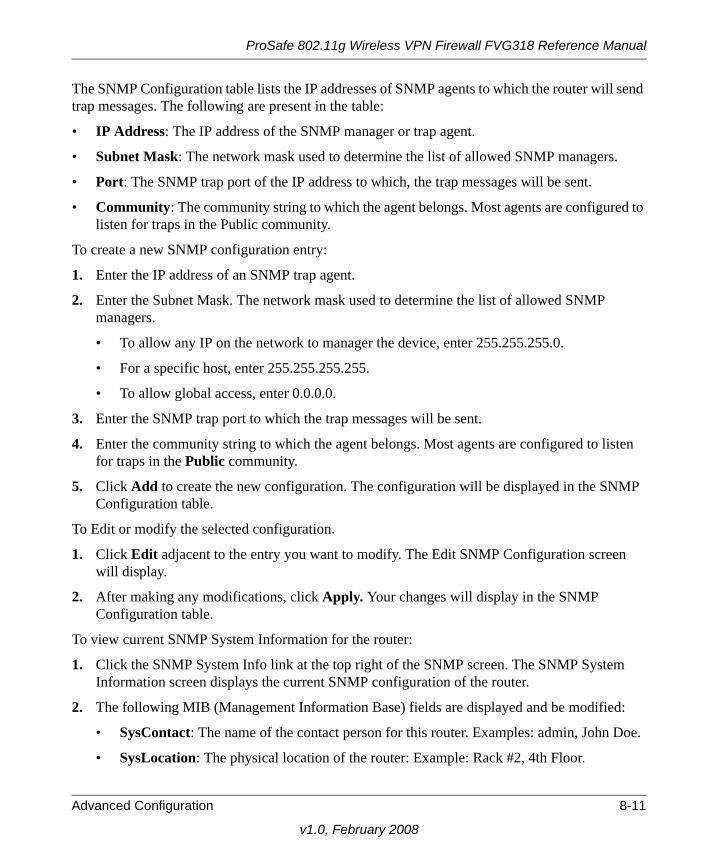
The SNMP Configuration table lists the IP addresses of SNMP agents to which the router will send trap messages. The following are present in the table:
• IP Address: The IP address of the SNMP manager or trap agent.
• Subnet Mask: The network mask used to determine the list of allowed SNMP managers.
• Port: The SNMP trap port of the IP address to which, the trap messages will be sent.
• Community: The community string to which the agent belongs. Most agents are configured to listen for traps in the Public community.
To create a new SNMP configuration entry:
1. Enter the IP address of an SNMP trap agent.
2. Enter the Subnet Mask. The network mask used to determine the list of allowed SNMP managers.
• To allow any IP on the network to manager the device, enter 255.255.255.0.
• For a specific host, enter 255.255.255.255.
• To allow global access, enter 0.0.0.0.
3. Enter the SNMP trap port to which the trap messages will be sent.
4. Enter the community string to which the agent belongs. Most agents are configured to listen for traps in the Public community.
5. Click Add to create the new configuration. The configuration will be displayed in the SNMP Configuration table.
To Edit or modify the selected configuration.
1. Click Edit adjacent to the entry you want to modify. The Edit SNMP Configuration screen will display.
2. After making any modifications, click Apply. Your changes will display in the SNMP Configuration table.
To view current SNMP System Information for the router:
1. Click the SNMP System Info link at the top right of the SNMP screen. The SNMP System Information screen displays the current SNMP configuration of the router.
2. The following MIB (Management Information Base) fields are displayed and be modified:
• SysContact: The name of the contact person for this router. Examples: admin, John Doe.
• SysLocation: The physical location of the router: Example: Rack #2, 4th Floor.
Advanced Configuration 8-11
v1.0, February 2008

ProSafe 802.11g Wireless VPN Firewall FVG318 Reference Manual
• SysName: A name given for easy identification of the router.
3. Click Apply to save any changes made to SNMP System Information for this router.
Enabling Universal Plug and Play (UPnP)
UPnP (Universal Plug and Play) allows for automatic discovery of devices that can communicate with this router. This feature should be used with caution as it breaches firewall security. Select Security > UPnP to display the UPnP screen.
To enable UPnP:
1. Select the Yes radio box for Do you want to enable UPnP? to enable UPnP. If disabled, the router will not allow for automatic device configuration.
2. Enter an Advertisement Period, in minutes, for how often this wireless gateway should broadcast its UPnP information to all devices within range.
3. Enter an Advertisement Time to Live, expressed in hops, for each UPnP packet. (This is the number of steps a packet is allowed to propagate before being discarded. Small values will limit the UPnP broadcast range (recommended).)
4. Click Apply to save your changes.
Figure 8-8
8-12 Advanced Configuration
v1.0, February 2008