Configure Cisco UCS Rack and Blade Servers with NVIDIA ... · NVIDIA GRID 2.0 for Citrix XenDesktop...
57
White Paper © 2017 Cisco and/or its affiliates. All rights reserved. This document is Cisco Public. Page 1 of 57 Configure Cisco UCS Rack and Blade Servers with NVIDIA GRID 2.0 for Citrix XenDesktop on VMware vSphere 6.0
Transcript of Configure Cisco UCS Rack and Blade Servers with NVIDIA ... · NVIDIA GRID 2.0 for Citrix XenDesktop...
White Paper
© 2017 Cisco and/or its affiliates. All rights reserved. This document is Cisco Public. Page 1 of 57
Configure Cisco UCS Rack and Blade Servers with NVIDIA GRID 2.0 for Citrix XenDesktop on VMware vSphere 6.0

© 2017 Cisco and/or its affiliates. All rights reserved. This document is Cisco Public. Page 2 of 57
Contents
What You Will Learn
Why Use NVIDIA GRID vGPU for Graphic Deployments on Citrix XenDesktop vGPU Profiles
Cisco Unified Computing System Cisco UCS Manager Cisco UCS Mini Cisco UCS 6300 Modular Fabric Interconnect for UCS Mini Cisco UCS 6324 Fabric Interconnect for UCS Mini Cisco UCS 6200 and 6300 Series Fabric Interconnects Cisco UCS 6248UP and 6296UP Fabric Interconnects Cisco UCS 6300 Series Fabric Interconnects and 2304 Fabric Extenders Cisco UCS C-Series Rack Servers Cisco UCS C240 M4 Rack Server Cisco UCS VIC 1227 Cisco UCS VIC 1387 Cisco UCS B200 M4 Blade Server Cisco UCS VIC 1340
NVIDIA GRID Cards NVIDIA GRID 2.0 Technology NVIDIA GRID 2.0 GPU NVIDIA GRID 2.0 License Requirements
VMware vSphere 6.0
Graphics Acceleration in Citrix XenDesktop and XenApp GPU Acceleration for Microsoft Windows Desktops GPU Acceleration for Microsoft Windows Server GPU Sharing for Citrix XenApp RDS Workloads
Citrix HDX 3D Pro Requirements
Solution Configuration
Configure Cisco UCS Install NVIDIA Tesla GPU Card on Cisco UCS C240 M4 Install NVIDIA Tesla GPU Card on Cisco UCS B200 M4
Configure the GPU Card Install the NVIDIA GRID Software Install the NVIDIA GRID License Server Configure the NVIDIA GRID 2.0 License Server Deploy the NVIDIA GRID vGPU Software Configure the VMware ESXi Host Server for vGPU NVIDIA Tesla M60, M10, and M6 Profile Specifications Prepare a Virtual Machine for vGPU Support Install the NVIDIA vGPU Software Driver and Citrix HDX 3D Pro Agent Verify That Applications Are Ready to Support vGPU Configure the Virtual Machine for an NVIDIA GRID vGPU License
Verify vGPU Deployment Verify That the NVIDIA Driver Is Running on the Desktop Verify NVDIA License Acquisition by Desktops Verify the NVDIA Configuration on the Host
Additional Configurations Install Citrix HDX 3D Pro Virtual Desktop Agent Using the CLI

© 2017 Cisco and/or its affiliates. All rights reserved. This document is Cisco Public. Page 3 of 57
Install and Upgrade NVIDIA Drivers Use Citrix HDX Monitor Optimize the Citrix HDX 3D Pro User Experience Use GPU Acceleration for Microsoft Windows Server DirectX, Direct3D, and WPF Rendering Use GPU Acceleration for Microsoft Windows Server: Experimental GPU Acceleration for NVIDIA CUDA and OpenCL Applications Use the OpenGL Software Accelerator
Conclusion
For More Information
© 2017 Cisco and/or its affiliates. All rights reserved. This document is Cisco Public. Page 4 of 57
What You Will Learn
Using the increased processing power of today’s Cisco UCS® B-Series Blade Servers and Cisco UCS C-Series
Rack Servers, applications with demanding graphics requirements are now being virtualized. To enhance the
capability to deliver these high-performance and graphics-intensive applications, Cisco offers support for the
NVIDIA GRID M6, M60, and M10 cards in the Cisco Unified Computing System™
(Cisco UCS) portfolio of PCI
Express (PCIe) or mezzanine form-factor cards for the Cisco UCS B-Series Blade Servers and Cisco UCS C-
Series Rack Servers.
With the addition of the new graphics processing capabilities, the engineering, design, imaging, and marketing
departments of organizations can now experience the benefits that desktop virtualization brings to the applications
they use. Users of Microsoft Windows 10 and Office 2016 or later versions can benefit from the new NVIDIA M10
high-density graphics card, deployable on Cisco UCS C240 M4 Rack Servers.
Note: NVIDIA M10 cards are supported in Cisco UCS Manager Release 3.1(3a) or later.
This new graphics capability helps enable organizations to centralize their graphics workloads and data in the data
center. This capability greatly benefits organizations that need to be able to shift work geographically. Until now,
graphics files have been too large to move, and the files have had to be local to the person using them to be
usable.
The Cisco UCS C-Series C240 M4 rack server offers these benefits:
● Support for full-length, full-power NVIDIA GRID cards in a 2-rack-unit (2RU) form factor
● Cisco UCS Manager integration for management of the servers and NVIDIA GRID cards
● End-to-end integration with Cisco UCS management solutions, including Cisco UCS Central Software and
Cisco UCS Director
● More efficient use of rack space with Cisco UCS C240 M4 Rack Servers with two NVIDIA GRID cards than
with the 2-slot, 2.5-inch equivalent rack unit: the HP ProLiant WS460c Gen9 Graphics Server Blade with the
GRID card in a second slot
The modular LAN-on-motherboard (mLOM) form-factor NVIDIA graphics card in the Cisco UCS B-Series offers
these benefits:
● Cisco UCS Manager integration for management of the servers and the NVIDIA GRID card in Cisco UCS
B200 M4 Blade Servers
● End-to-end integration with Cisco UCS management solutions, including Cisco UCS Central Software and
Cisco UCS Director
An important element of this document’s design is VMware’s support for the NVIDIA GRID Virtual Graphics
Processing Unit (vGPU) feature in VMware vSphere 6. Prior versions of vSphere supported only virtual direct
graphics acceleration (vDGA) and virtual shared graphics acceleration (vSGA), so support for vGPU in vSphere 6
greatly expands the range of deployment scenarios using the most versatile and efficient configuration of the GRID
cards.
© 2017 Cisco and/or its affiliates. All rights reserved. This document is Cisco Public. Page 5 of 57
The purpose of this document is to help our partners and customers integrate NVIDIA GRID 2.0 graphics
processing cards, Cisco UCS B200 M4 servers, and Cisco UCS C240 M4 servers on VMware vSphere with Citrix
XenDesktop in vGPU mode.
Please contact our partners NVIDIA, Citrix, and VMware for lists of applications that are supported by the card,
hypervisor, and desktop broker in each mode.
Our objective here is to provide the reader with specific methods for integrating Cisco UCS servers with NVIDIA
GRID M6, M60, and M10 cards with VMware vSphere and Citrix products so that the servers, hypervisor, and
virtual desktops are ready for installation of graphics intense applications.
Why Use NVIDIA GRID vGPU for Graphic Deployments on Citrix XenDesktop
The NVIDIA GRID vGPU allows multiple virtual desktops to share a single physical GPU, and it allows multiple
GPUs to reside on a single physical PCI card. All provide the 100 percent application compatibility of vDGA pass-
through graphics, but with lower cost because multiple desktops share a single graphics card. With Citrix
XenDesktop, you can centralize, pool, and more easily manage traditionally complex and expensive distributed
workstations and desktops. Now all your user groups can take advantage of the benefits of virtualization.
The GRID vGPU capability brings the full benefits of NVIDIA hardware-accelerated graphics to virtualized
solutions. This technology provides exceptional graphics performance for virtual desktops equivalent to PCs with
an onboard graphics processor.
The GRID vGPU uses the industry's most advanced technology for sharing true GPU hardware acceleration
among multiple virtual desktops—without compromising the graphics experience. Application features and
compatibility are exactly the same as they would be on a physical desktop.
With GRID vGPU technology, the graphics commands of each virtual machine are passed directly to the GPU,
without translation by the hypervisor. By allowing multiple virtual machines to access the power of a single GPU in
the virtualization server, enterprises can increase the number of users with access to true GPU-based graphics
acceleration on virtual machines.
The physical GPU in the server can be configured with a specific vGPU profile. Organizations have a great deal of
flexibility in how best to configure their servers to meet the needs of various types of end users.
vGPU support allows businesses to use the power of the NVIDIA GRID technology to create a whole new class of
virtual machines designed to provide end users with a rich, interactive graphics experience.
vGPU Profiles
In any given enterprise, the needs of individual users vary widely. One of the main benefits of the GRID vGPU is
the flexibility to use various vGPU profiles designed to serve the needs of different classes of end users.
Although the needs of end users can be diverse, for simplicity users can be grouped into the following categories:
knowledge workers, designers, and power users.
● For knowledge workers, the main areas of importance include office productivity applications, a robust web
experience, and fluid video playback. Knowledge workers have the least-intensive graphics demands, but
they expect the same smooth, fluid experience that exists natively on today’s graphics-accelerated devices
such as desktop PCs, notebooks, tablets, and smartphones.

© 2017 Cisco and/or its affiliates. All rights reserved. This document is Cisco Public. Page 6 of 57
● Power users are users who need to run more demanding office applications, such as office productivity
software, image editing software such as Adobe Photoshop, mainstream computer-aided design (CAD)
software such as Autodesk AutoCAD, and product lifecycle management (PLM) applications. These
applications are more demanding and require additional graphics resources with full support for APIs such
as OpenGL and Direct3D.
● Designers are users in an organization who run demanding professional applications such as high-end CAD
software and professional digital content creation (DCC) tools. Examples include Autodesk Inventor, PTC
Creo, Autodesk Revit, and Adobe Premiere. Historically, designers have used desktop workstations and
have been a difficult group to incorporate into virtual deployments because of their need for high-end
graphics and the certification requirements of professional CAD and DCC software.
vGPU profiles allow the GPU hardware to be time-sliced to deliver exceptional shared virtualized graphics
performance (Figure 1).
Figure 1. NVIDIA GRID vGPU GPU System Architecture
© 2017 Cisco and/or its affiliates. All rights reserved. This document is Cisco Public. Page 7 of 57
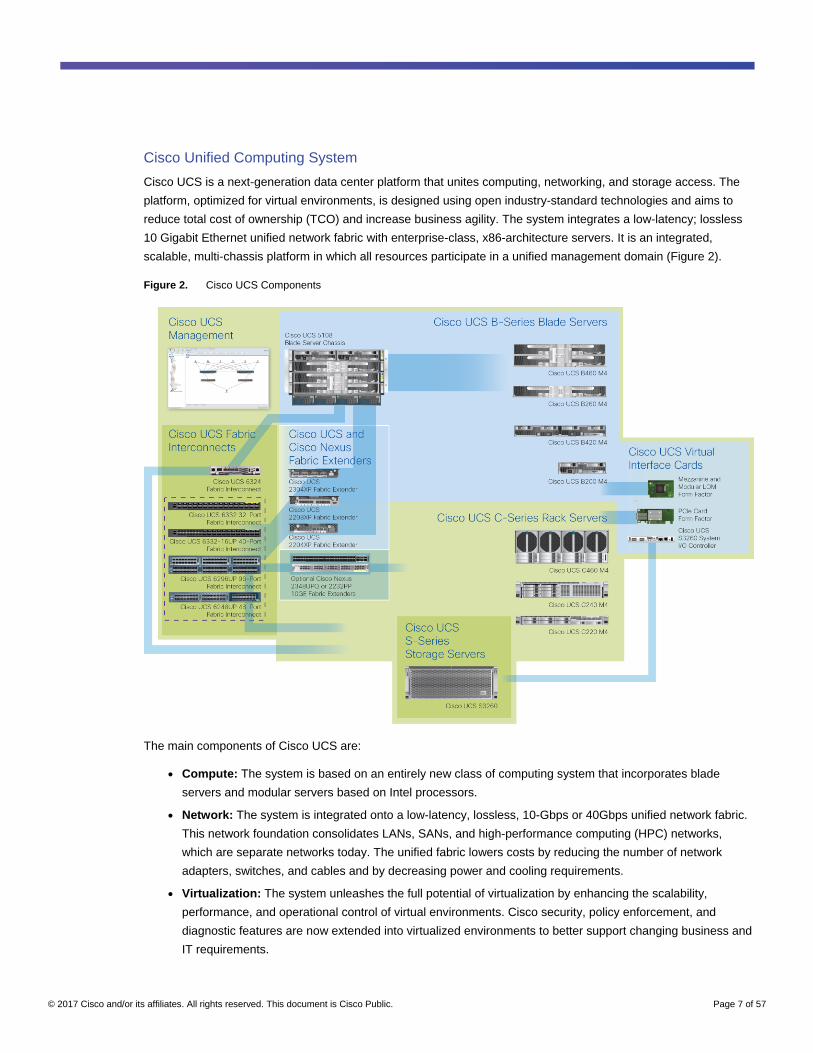
Cisco Unified Computing System
Cisco UCS is a next-generation data center platform that unites computing, networking, and storage access. The
platform, optimized for virtual environments, is designed using open industry-standard technologies and aims to
reduce total cost of ownership (TCO) and increase business agility. The system integrates a low-latency; lossless
10 Gigabit Ethernet unified network fabric with enterprise-class, x86-architecture servers. It is an integrated,
scalable, multi-chassis platform in which all resources participate in a unified management domain (Figure 2).
Figure 2. Cisco UCS Components
The main components of Cisco UCS are:
● Compute: The system is based on an entirely new class of computing system that incorporates blade
servers and modular servers based on Intel processors.
● Network: The system is integrated onto a low-latency, lossless, 10-Gbps or 40Gbps unified network fabric.
This network foundation consolidates LANs, SANs, and high-performance computing (HPC) networks,
which are separate networks today. The unified fabric lowers costs by reducing the number of network
adapters, switches, and cables and by decreasing power and cooling requirements.
● Virtualization: The system unleashes the full potential of virtualization by enhancing the scalability,
performance, and operational control of virtual environments. Cisco security, policy enforcement, and
diagnostic features are now extended into virtualized environments to better support changing business and
IT requirements.
© 2017 Cisco and/or its affiliates. All rights reserved. This document is Cisco Public. Page 8 of 57
● Storage: The system provides consolidated access to local storage, SAN storage, and network-attached
storage (NAS) over the unified fabric. With storage access unified, Cisco UCS can access storage over
Ethernet, Fibre Channel, Fibre Channel over Ethernet (FCoE), and Small Computer System Interface over
IP (iSCSI) protocols. This capability provides customers with choice for storage access and investment
protection. In addition, server administrators can pre-assign storage-access policies for system connectivity
to storage resources, simplifying storage connectivity and management and helping increase productivity.
● Management: Cisco UCS uniquely integrates all system components, enabling the entire solution to be
managed as a single entity by Cisco UCS Manager. The manager has an intuitive GUI, a command-line
interface (CLI), and a robust API for managing all system configuration processes and operations.
Cisco UCS is designed to deliver:
● Reduced TCO and increased business agility
● Increased IT staff productivity through just-in-time provisioning and mobility support
● A cohesive, integrated system that unifies the technology in the data center; the system is managed,
serviced, and tested as a whole
● Scalability through a design for hundreds of discrete servers and thousands of virtual machines and the
capability to scale I/O bandwidth to match demand
● Industry standards supported by a partner ecosystem of industry leaders
Cisco UCS Manager
Cisco UCS Manager provides unified, embedded management of all software and hardware components of Cisco
UCS through an intuitive GUI, a CLI, and an XML API. The manager provides a unified management domain with
centralized management capabilities and can control multiple chassis and thousands of virtual machines.
Cisco UCS Mini
Cisco UCS Mini is incorporated into this solution to manage the Cisco UCS C240 M4 server and the NVIDIA GRID
cards. In addition, Cisco UCS Mini hosts the virtual infrastructure components such as the domain controllers and
desktop broker using Cisco UCS B200 M4 Blade Servers. Cisco UCS Mini is an optional part of this reference
architecture. Another choice for managing the Cisco UCS and NVIDIA equipment is the Cisco UCS 6200 Series
Fabric Interconnects.
Cisco UCS Mini is designed for customers who need fewer servers but still want the robust management
capabilities provided by Cisco UCS Manager. This solution delivers servers, storage, and 10 Gigabit networking in
an easy-to-deploy, compact form factor (Figure 3).

© 2017 Cisco and/or its affiliates. All rights reserved. This document is Cisco Public. Page 9 of 57
Figure 3. Cisco UCS Mini
Cisco UCS Mini consists of the following components:
● Cisco UCS 5108 Blade Server Chassis: A chassis can accommodate up to eight half-width Cisco UCS
B200 M4 Blade Servers.
● Cisco UCS B200 M4 Blade Server: Delivering performance, versatility, and density without compromise,
the Cisco UCS B200 M4 addresses a broad set of workloads.
● Cisco UCS 6324 Fabric Interconnect: The Cisco UCS 6324 provides the same unified server and
networking capabilities as the top-of-rack Cisco UCS 6200 Series Fabric Interconnects embedded in the
Cisco UCS 5108 Blade Server Chassis.
● Cisco UCS Manager: Cisco UCS Manager provides unified, embedded management of all software and
hardware components in a Cisco UCS Mini solution.
Cisco UCS 6300 Modular Fabric Interconnect for UCS Mini
Cisco UCS 6300 Series Fabric Interconnects provide the management and communication backbone for the Cisco
UCS B-Series Blade Servers, 5100 Series Blade Server Chassis, and C-Series Rack Servers. In addition, the
firmware for the NVIDIA GRID cards can be managed using both the 6300 and 6200 Series Fabric Interconnects,
an exclusive feature of the Cisco UCS portfolio.
The chassis, blades, and rack-mount servers that are attached to the interconnects are part of a single highly
available management domain. By supporting unified fabric, the fabric interconnects provide the flexibility to
support LAN and storage connectivity for all blades in the domain at configuration time.
Typically deployed in redundant pairs, the 6300 Series Fabric Interconnects deliver uniform access to both
networks and storage to help create a fully virtualized environment.
© 2017 Cisco and/or its affiliates. All rights reserved. This document is Cisco Public. Page 10 of 57
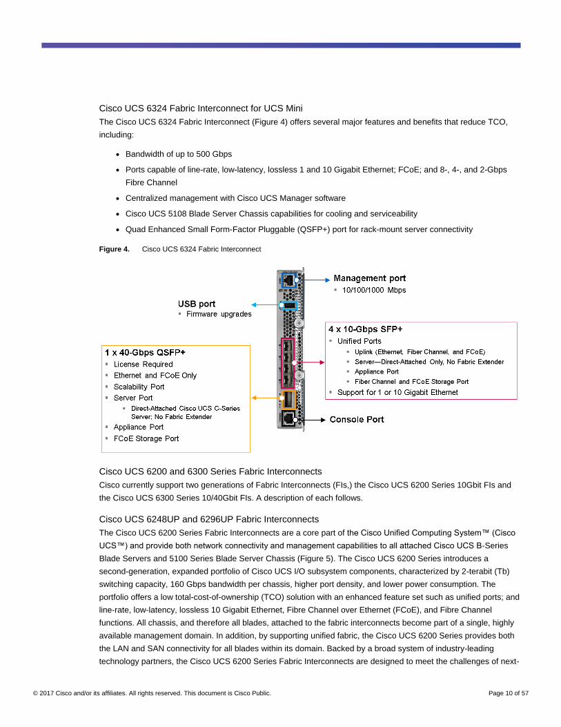
Cisco UCS 6324 Fabric Interconnect for UCS Mini
The Cisco UCS 6324 Fabric Interconnect (Figure 4) offers several major features and benefits that reduce TCO,
including:
● Bandwidth of up to 500 Gbps
● Ports capable of line-rate, low-latency, lossless 1 and 10 Gigabit Ethernet; FCoE; and 8-, 4-, and 2-Gbps
Fibre Channel
● Centralized management with Cisco UCS Manager software
● Cisco UCS 5108 Blade Server Chassis capabilities for cooling and serviceability
● Quad Enhanced Small Form-Factor Pluggable (QSFP+) port for rack-mount server connectivity
Figure 4. Cisco UCS 6324 Fabric Interconnect
Cisco UCS 6200 and 6300 Series Fabric Interconnects
Cisco currently support two generations of Fabric Interconnects (FIs,) the Cisco UCS 6200 Series 10Gbit FIs and
the Cisco UCS 6300 Series 10/40Gbit FIs. A description of each follows.
Cisco UCS 6248UP and 6296UP Fabric Interconnects
The Cisco UCS 6200 Series Fabric Interconnects are a core part of the Cisco Unified Computing System™ (Cisco
UCS™) and provide both network connectivity and management capabilities to all attached Cisco UCS B-Series
Blade Servers and 5100 Series Blade Server Chassis (Figure 5). The Cisco UCS 6200 Series introduces a
second-generation, expanded portfolio of Cisco UCS I/O subsystem components, characterized by 2-terabit (Tb)
switching capacity, 160 Gbps bandwidth per chassis, higher port density, and lower power consumption. The
portfolio offers a low total-cost-of-ownership (TCO) solution with an enhanced feature set such as unified ports; and
line-rate, low-latency, lossless 10 Gigabit Ethernet, Fibre Channel over Ethernet (FCoE), and Fibre Channel
functions. All chassis, and therefore all blades, attached to the fabric interconnects become part of a single, highly
available management domain. In addition, by supporting unified fabric, the Cisco UCS 6200 Series provides both
the LAN and SAN connectivity for all blades within its domain. Backed by a broad system of industry-leading
technology partners, the Cisco UCS 6200 Series Fabric Interconnects are designed to meet the challenges of next-

© 2017 Cisco and/or its affiliates. All rights reserved. This document is Cisco Public. Page 11 of 57
generation data centers, including dense multisocket, multicore, virtual machine–optimized services, in which
infrastructure sprawl and increasingly demanding workloads are commonplace.
Cisco’s second-generation fabric interconnects are available in 48 port and 96 port densities, shown in the figures
below:
Figure 5. Cisco UCS 6248UP Fabric Interconnect
Figure 6. Cisco UCS 6296UP Fabric Interconnect
Cisco UCS 6300 Series Fabric Interconnects and 2304 Fabric Extenders
The Cisco UCS 6300 Series Fabric Interconnects are a core part of Cisco UCS, providing both network
connectivity and management capabilities for the system (Figure 7). The Cisco UCS 6300 Series offers line-rate,
low-latency, lossless 10 and 40 Gigabit Ethernet, Fibre Channel over Ethernet (FCoE), and Fibre Channel
functions.
The Cisco UCS 6300 Series provides the management and communication backbone for the Cisco UCS B-Series
Blade Servers, 5100 Series Blade Server Chassis, and C-Series Rack Servers managed by Cisco UCS. All servers
attached to the fabric interconnects become part of a single, highly available management domain. In addition, by
supporting unified fabric, the Cisco UCS 6300 Series provides both LAN and SAN connectivity for all servers within
its domain.
From a networking perspective, the Cisco UCS 6300 Series uses a cut-through architecture, supporting
deterministic, low-latency, line-rate 10 and 40 Gigabit Ethernet ports, switching capacity of 2.56 terabits per second
(Tbps), and 320 Gbps of bandwidth per chassis, independent of packet size and enabled services. The product
family supports Cisco®low-latency, lossless 10 and 40 Gigabit Ethernet[1] unified network fabric capabilities, which
increase the reliability, efficiency, and scalability of Ethernet networks. The fabric interconnect supports multiple
traffic classes over a lossless Ethernet fabric from the server through the fabric interconnect. Significant TCO
savings can be achieved with an FCoE optimized server design in which network interface cards (NICs), host bus
adapters (HBAs), cables, and switches can be consolidated.

© 2017 Cisco and/or its affiliates. All rights reserved. This document is Cisco Public. Page 12 of 57
Figure 7. Cisco UCS 6300 Series Fabric Interconnects
Cisco UCS C-Series Rack Servers
Cisco UCS C-Series Rack Servers keep pace with Intel® Xeon® processor innovation by offering the latest
processors with an increase in processor frequency and improved security and availability features. With the
increased performance provided by the Intel Xeon processor E5-2600 v4 and v3 product families, C-Series servers
offer an improved price-to-performance ratio. They also extend Cisco UCS innovations to an industry-standard
rack-mount form factor, including a standards-based unified network fabric, Cisco® VN-Link virtualization support,
and Cisco Extended Memory Technology.
Designed to operate both in standalone environments and as part of Cisco UCS, these servers enable
organizations to deploy systems incrementally—using as many or as few servers as needed—on a schedule that
best meets the organization’s timing and budget. C-Series servers offer investment protection through the
capability to deploy them either as standalone servers or as part of Cisco UCS.
One compelling reason that many organizations prefer rack-mount servers is the wide range of I/O options
available in the form of PCIe adapters. C-Series servers support a broad range of I/O options, including interfaces
supported by Cisco as well as adapters from third parties.
Cisco UCS C240 M4 Rack Server
The Cisco UCS C240 M4 Rack Server (Figures 8 and 9 and Table 1) is designed for both performance and
expandability over a wide range of storage-intensive infrastructure workloads, from big data to collaboration.
The enterprise-class Cisco UCS C240 M4 server extends the capabilities of the Cisco UCS portfolio in a 2RU form
factor with the addition of the Intel Xeon processor E5-2600 v4 and v3 product family, which delivers a superb
combination of performance, flexibility, and efficiency
The enterprise-class Cisco UCS C240 M4 server extends the capabilities of the Cisco UCS portfolio in a 2RU form
factor. Based on the Intel Xeon processor E5-2600 v4 and v3 series, it delivers an outstanding combination of
performance, flexibility, and efficiency. In addition, the C240 M4 offers outstanding levels of internal memory and
storage expandability with exceptional performance. It delivers:
● Up to 24 DDR4 DIMMs at speeds up to 2400 MHz for improved performance and lower power consumption
● Up to 6 PCIe 3.0 slots (4 full-height, full-length)
● Up to 24 small-form-factor (SFF) drives or 12 large-form-factor (LFF) drives, plus two (optional) internal
SATA boot drives
● Support for 12-Gbps SAS drives
● An mLOM slot for installing a next-generation Cisco virtual interface card (VIC) or third-party network
interface card (NIC) without consuming a PCIe slot

© 2017 Cisco and/or its affiliates. All rights reserved. This document is Cisco Public. Page 13 of 57
● Two 1 Gigabit Ethernet embedded LOM ports
● Support for up to 2 double-wide NVIDIA graphics processing units (GPUs), providing a graphics-rich
experience to more virtual users
● Excellent reliability, availability, and serviceability (RAS) features with tool-free CPU insertion, easy-to-use
latching lid, hot-swappable and hot-pluggable components, and redundant Cisco Flexible Flash (FlexFlash)
Secure Digital (SD) cards.
The C240 M4 also increases performance and customer choice over many types of storage-intensive applications
such as:
● Collaboration
● Small and medium-sized business (SMB) databases
● Big data infrastructure
● Virtualization and consolidation
● Storage servers
● High-performance appliances
The C240 M4 can be deployed as a standalone server or as part of Cisco UCS. Cisco UCS unifies computing,
networking, management, virtualization, and storage access into a single integrated architecture that enables end-
to-end server visibility, management, and control in both bare-metal and virtualized environments. Within a Cisco
UCS deployment, the C240 M4 takes advantage of Cisco’s standards-based unified computing innovations, which
significantly reduce customers’ TCO and increase business agility.
For more information about the Cisco UCS C240 M4 Rack Server, see
http://www.cisco.com/c/en/us/products/servers-unified-computing/ucs-c240-m4-rack-server/index.html.
Figure 8. Cisco UCS C240 M4 Rack Server Front View
Figure 9. Cisco UCS C240 M4 Rack Server Rear View
!
Intel
Inside
XEON
UCSC240 M4
Con
sole
UC
S-H
DD
30
0G
I2F
10
5
15
K S
AS
30
0 G
B
!
1 6 12 18 24
UC
S-H
DD
30
0G
I2F
10
5
15
K S
AS
30
0 G
B
!
UC
S-H
DD
30
0G
I2F
10
5
15
K S
AS
30
0 G
B
!
UC
S-H
DD
30
0G
I2F
10
5
15
K S
AS
30
0 G
B
!
UC
S-H
DD
30
0G
I2F
10
5
15
K S
AS
30
0 G
B
!
UC
S-H
DD
30
0G
I2F
10
5
15
K S
AS
30
0 G
B
!
UC
S-H
DD
30
0G
I2F
10
5
15
K S
AS
30
0 G
B
!
UC
S-H
DD
30
0G
I2F
10
5
15
K S
AS
30
0 G
B
!
UC
S-H
DD
30
0G
I2F
10
5
15
K S
AS
30
0 G
B
!
UC
S-H
DD
30
0G
I2F
10
5
15
K S
AS
30
0 G
B
!
UC
S-H
DD
30
0G
I2F
10
5
15
K S
AS
30
0 G
B
!
UC
S-H
DD
30
0G
I2F
10
5
15
K S
AS
30
0 G
B
!
UC
S-H
DD
30
0G
I2F
10
5
15
K S
AS
30
0 G
B
!
UC
S-H
DD
30
0G
I2F
10
5
15
K S
AS
30
0 G
B
!
UC
S-H
DD
30
0G
I2F
10
5
15
K S
AS
30
0 G
B
!
UC
S-H
DD
30
0G
I2F
10
5
15
K S
AS
30
0 G
B
!
UC
S-H
DD
30
0G
I2F
10
5
15
K S
AS
30
0 G
B
!
UC
S-H
DD
30
0G
I2F
10
5
15
K S
AS
30
0 G
B
!
UC
S-H
DD
30
0G
I2F
10
5
15
K S
AS
30
0 G
B
!
UC
S-H
DD
30
0G
I2F
10
5
15
K S
AS
30
0 G
B
!
UC
S-H
DD
30
0G
I2F
10
5
15
K S
AS
30
0 G
B
!
UC
S-H
DD
30
0G
I2F
10
5
15
K S
AS
30
0 G
B
!
UC
S-H
DD
30
0G
I2F
10
5
15
K S
AS
30
0 G
B
!
UC
S-H
DD
30
0G
I2F
10
5
15
K S
AS
30
0 G
B
!
© 2017 Cisco and/or its affiliates. All rights reserved. This document is Cisco Public. Page 14 of 57
Table 1. Cisco UCS C240 M4 PCIe Slots
PCIe Slot Length Lane
1 ¾ x8
2 Full x16
3 Full x8
4 ¾ x8
5 Full x16
6 Full x8
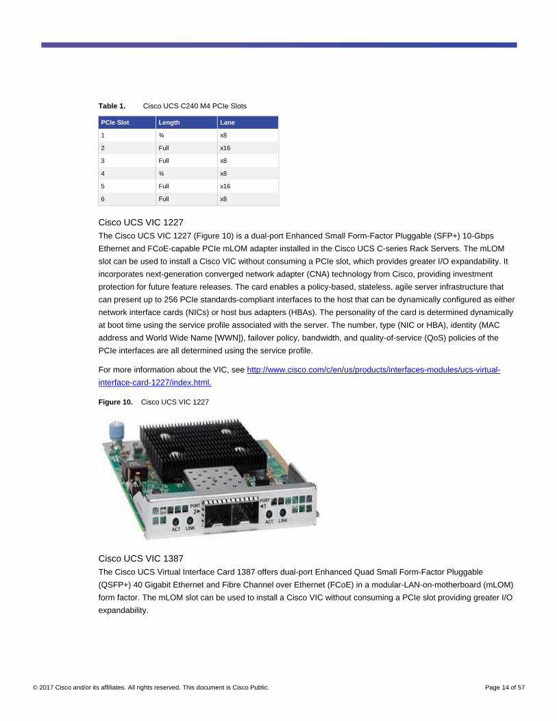
Cisco UCS VIC 1227
The Cisco UCS VIC 1227 (Figure 10) is a dual-port Enhanced Small Form-Factor Pluggable (SFP+) 10-Gbps
Ethernet and FCoE-capable PCIe mLOM adapter installed in the Cisco UCS C-series Rack Servers. The mLOM
slot can be used to install a Cisco VIC without consuming a PCIe slot, which provides greater I/O expandability. It
incorporates next-generation converged network adapter (CNA) technology from Cisco, providing investment
protection for future feature releases. The card enables a policy-based, stateless, agile server infrastructure that
can present up to 256 PCIe standards-compliant interfaces to the host that can be dynamically configured as either
network interface cards (NICs) or host bus adapters (HBAs). The personality of the card is determined dynamically
at boot time using the service profile associated with the server. The number, type (NIC or HBA), identity (MAC
address and World Wide Name [WWN]), failover policy, bandwidth, and quality-of-service (QoS) policies of the
PCIe interfaces are all determined using the service profile.
For more information about the VIC, see http://www.cisco.com/c/en/us/products/interfaces-modules/ucs-virtual-
interface-card-1227/index.html.
Figure 10. Cisco UCS VIC 1227
Cisco UCS VIC 1387
The Cisco UCS Virtual Interface Card 1387 offers dual-port Enhanced Quad Small Form-Factor Pluggable
(QSFP+) 40 Gigabit Ethernet and Fibre Channel over Ethernet (FCoE) in a modular-LAN-on-motherboard (mLOM)
form factor. The mLOM slot can be used to install a Cisco VIC without consuming a PCIe slot providing greater I/O
expandability.

© 2017 Cisco and/or its affiliates. All rights reserved. This document is Cisco Public. Page 15 of 57
Figure 11. Cisco UCS VIC 1387
Cisco UCS B200 M4 Blade Server
The enterprise-class Cisco UCS B200 M4 Blade Server (Figure 12) extends the capabilities of the Cisco UCS
portfolio in a half-width blade form factor. The B200 M4 uses the power of the latest Intel Xeon processor E5-2600
v3 and v4 series CPUs with up to 1.5 TB of RAM (using 64 GB DIMMs), two solid-state disks (SSDs) or hard-disk
drives (HDDs), and throughput of up to 80 Gbps. The B200 M4 server mounts in a Cisco UCS 5100 Series Blade
Server Chassis or Cisco UCS Mini blade server chassis. It has 24 total slots for error-correcting code (ECC)
registered DIMMs (RDIMMs) or load-reduced DIMMs (LR DIMMs) for up to 1.5 TB of total memory capacity (Cisco
UCS B200 M4 configured with two CPUs using 64 GB DIMMs). It supports one connector for the Cisco UCS VIC
1340 or 1240 adapter, which provides Ethernet and FCoE. A second mezzanine card slot also is available, which
can be used for the NVIDIA M6 graphics cards.
For more information, see http://www.cisco.com/c/en/us/products/servers-unified-computing/ucs-b200-m4-blade-
server/index.html.
Figure 12. Cisco UCS B200 M4 Blade Server Front View
Cisco UCS VIC 1340
The Cisco UCS VIC 1340 (Figure 13) is a 2-port 40-Gbps Ethernet or dual 4 x 10-Gbps Ethernet, FCoE-capable
mLOM designed exclusively for the M4 generation of Cisco UCS B-Series Blade Servers. When used in
combination with an optional port expander, the VIC 1340 is enabled for two ports of 40-Gbps Ethernet. The VIC
1340 enables a policy-based, stateless, agile server infrastructure that can present more than 256 PCIe standards-
compliant interfaces to the host that can be dynamically configured as either NICs or HBAs. In addition, the VIC
1340 supports Cisco Virtual Machine Fabric Extender (VM-FEX) technology, which extends the Cisco UCS fabric
interconnect ports to virtual machines, simplifying server virtualization deployment and management.
For more information, see http://www.cisco.com/c/en/us/products/interfaces-modules/ucs-virtual-interface-card-
1340/index.html.

© 2017 Cisco and/or its affiliates. All rights reserved. This document is Cisco Public. Page 16 of 57
Figure 13. Cisco UCS VIC 1340
NVIDIA GRID Cards
For desktop virtualization applications, the NVIDIA Tesla M6, M10, and M60 cards are an optimal choice for high-
performance graphics (Table 2).
Table 2. Technical Specifications for NVIDIA GRID Cards
Number of GPUs Single high-end Maxwell Quad midlevel Maxwell Dual high-end Maxwell
NVIDIA Compute Unified Device Architecture (CUDA) Cores
1536 2560 (640 per GPU) 4096 (2048 per GPU)
Memory Size 8-GB GDDR5 32-GB GDDR5
(8 GB per GPU)
16-GB GDDR5
(8 GB per GPU)
Maximum Number of vGPU Instances
16 64 32
Power 100 watts (W; 75W optimal) 225W 240W or 300W (225W optimal)
Form Factor MXM (blade servers) P PCIe 3.0 dual slot
(rack servers)
PCIe 3.0 dual slot
(rack servers
Cooling Solution Bare board Passive Active and passive
H.264 1080p30 Streams 2 18 28 36
Maximum Number of Users per Board
16 64 (16 per GPU) 32 (16 per GPU)
Virtualization Use Case Blade optimized User-density optimized Performance optimized
NVIDIA GRID 2.0 Technology
NVIDIA GRID is the industry's most advanced technology for sharing vGPUs across multiple virtual desktop and
application instances. You can now use the full power of NVIDIA data center GPUs to deliver a superior virtual
graphics experience to any device anywhere. The NVIDIA GRID platform offers the highest levels of performance,
flexibility, manageability, and security—offering the right level of user experience for any virtual workflow.
For more information about NVIDIA GRID technology, see http://www.nvidia.com/object/grid-technology.html.
© 2017 Cisco and/or its affiliates. All rights reserved. This document is Cisco Public. Page 17 of 57
NVIDIA GRID 2.0 GPU
The NVIDIA GRID solution runs on top of award-winning, NVIDIA Maxwell-powered GPUs. These GPUs come in
two server form factors: the NVIDIA Tesla M6 for blade servers and converged infrastructure, and the NVIDIA
Tesla M10 and M60 for rack and tower servers.
NVIDIA GRID 2.0 License Requirements
GRID 2.0 requires concurrent user licenses and an on-premises NVIDIA license server to manage the licenses.
When the guest OS boots up, it contacts the NVIDIA license server and consumes one concurrent license. When
the guest OS shuts down, the license is returned to the pool.
GRID 2.0 also requires the purchase of a 1:1 ratio of concurrent licenses to NVIDIA Support, Update, and
Maintenance Subscription (SUMS) instances.
The following NVIDIA GRID products are available as licensed products on NVIDIA Tesla GPUs:
● Virtual workstation
● Virtual PC
● Virtual applications
For complete details about GRID 2.0 license requirements, see https://images.nvidia.com/content/grid/pdf/GRID-
Licensing-Guide.pdf.
VMware vSphere 6.0
VMware provides virtualization software. VMware’s enterprise software hypervisors for servers—VMware vSphere
ESX, vSphere ESXi, and VSphere—are bare-metal hypervisors that run directly on server hardware without
requiring an additional underlying operating system. VMware vCenter Server for vSphere provides central
management and complete control and visibility into clusters, hosts, virtual machines, storage, networking, and
other critical elements of your virtual infrastructure.
vSphere 6.0 introduces many enhancements to vSphere Hypervisor, VMware virtual machines, vCenter Server,
virtual storage, and virtual networking, further extending the core capabilities of the vSphere platform.
The vSphere 6.0 platform includes these features:
● Computing
◦ Increased scalability: vSphere 6.0 supports larger maximum configuration sizes. Virtual machines
support up to 128 virtual CPUs (vCPUs) and 4 TB of virtual RAM (vRAM). Hosts support up to 480 CPUs
and 12 TB of RAM, 1024 virtual machines per host, and 64 nodes per cluster.
◦ Expanded support: Get expanded support for the latest x86 chip sets, devices, drivers, and guest
operating systems. For a complete list of guest operating systems supported, see the VMware
Compatibility Guide.
◦ Outstanding graphics: The NVIDIA GRID vGPU delivers the full benefits of NVIDIA hardware-
accelerated graphics to virtualized solutions.
◦ Instant cloning: Technology built in to vSphere 6.0 lays the foundation for rapid cloning and deployment
of virtual machines—up to 10 times faster than what is possible today.

© 2017 Cisco and/or its affiliates. All rights reserved. This document is Cisco Public. Page 18 of 57
● Storage
◦ Transformation of virtual machine storage: vSphere Virtual Volumes enable your external storage
arrays to become virtual machine aware. Storage policy–based management (SPBM) enables common
management across storage tiers and dynamic storage class-of-service (CoS) automation. Together
these features enable exact combinations of data services (such as clones and snapshots) to be
instantiated more efficiently on a per–virtual machine basis.
● Network
◦ Network I/O control: New support for per–virtual machine VMware Distributed Virtual Switch (DVS)
bandwidth reservation helps ensure isolation and enforce limits on bandwidth.
◦ Multicast snooping: Support for Internet Group Management Protocol (IGMP) snooping for IPv4
packets and Multicast Listener Discovery (MLD) snooping for IPv6 packets in VDS improves
performance and scalability with multicast traffic.
◦ Multiple TCP/IP stacks for VMware vMotion: Implement a dedicated networking stack for vMotion
traffic, simplifying IP address management with a dedicated default gateway for vMotion traffic.
● Availability
◦ vMotion enhancements: Perform nondisruptive live migration of workloads across virtual switches and
vCenter Servers and over distances with a round-trip time (RTT) of up to 100 milliseconds (ms). This
support for dramatically longer RTT—a 10x increase in the supported time—for long-distance vMotion
now enables data centers physically located in New York and London to migrate live workloads between
one another.
◦ Replication-assisted vMotion: Customers with active-active replication set up between two sites can
perform more efficient vMotion migration, resulting in huge savings in time and resources, with up to 95
percent more efficient migration depending on the amount of data moved.
◦ Fault tolerance (up to 4 vCPUs): Get expanded support for software-based fault tolerance for
workloads with up to four vCPUs.
● Management
◦ Content library: This centralized repository provides simple and effective management for content,
including virtual machine templates, ISO images, and scripts. With vSphere Content Library, you can
now store and manage content from a central location and share content through a publish-and-
subscribe model.
◦ Cloning and migration across vCenter: Copy and move virtual machines between hosts on different
vCenter Servers in a single action.
◦ Enhanced user interface: vSphere Web Client is more responsive, more intuitive, and simpler than ever
before.
© 2017 Cisco and/or its affiliates. All rights reserved. This document is Cisco Public. Page 19 of 57
Graphics Acceleration in Citrix XenDesktop and XenApp
Citrix HDX 3D Pro enables you to deliver the desktops and applications that perform best with a GPU for hardware
acceleration, including 3D professional graphics applications based on OpenGL and DirectX. (The standard virtual
delivery agent [VDA] supports GPU acceleration of DirectX only.)
Examples of 3D professional applications include:
● Computer-aided design (CAD), manufacturing (CAM), and engineering (CAE) applications
● Geographical information system (GIS) software
● Picture archiving and communication system (PACS) for medical imaging
● Applications using the latest OpenGL, DirectX, NVIDIA CUDA, and OpenCL versions
● Computationally intensive nongraphical applications that use CUDA GPUs for parallel computing
HDX 3D Pro provides an outstanding user experience over any bandwidth:
● On WAN connections: Delivers an interactive user experience over WAN connections with bandwidth as
low as 1.5 Mbps
● On LAN connections: Delivers a user experience equivalent to that of a local desktop on LAN connections
with bandwidth of 100 Mbps
You can replace complex and expensive workstations with simpler user devices by moving graphics processing
into the data center for centralized management.
HDX 3D Pro provides GPU acceleration for Microsoft Windows desktops and Microsoft Windows Server. When
used with VMware vSphere 6 and NVIDIA GRID GPUs, HDX 3D Pro provides vGPU acceleration for Windows
desktops. For more information, see Citrix Virtual GPU Solution.
GPU Acceleration for Microsoft Windows Desktops
With Citrix HDX 3D Pro, you can deliver graphics-intensive applications as part of hosted desktops or applications
on desktop OS machines. HDX 3D Pro supports physical host computers (including desktop, blade, and rack
workstations) and GPU pass-through and GPU virtualization technologies offered by VMware vSphere Hypervisor.
Using GPU pass-through, you can create virtual machines with exclusive access to dedicated graphics processing
hardware. You can install multiple GPUs on the hypervisor and assign virtual machines to each of these GPUs on
a one-to-one basis.
Using GPU virtualization, multiple virtual machines can directly access the graphics processing power of a single
physical GPU. The true hardware GPU sharing provides desktops suitable for users with complex and demanding
design requirements. GPU virtualization for NVIDIA GRID cards uses the same NVIDIA graphics drivers as are
deployed on nonvirtualized operating systems.
HDX 3D Pro offers the following features:
● Adaptive H.264-based deep compression for optimal WAN and wireless performance: HDX 3D Pro
uses CPU-based full-screen H.264 compression as the default compression technique for encoding.
Hardware encoding is used with NVIDIA cards that support NVIDIA NVENC.
© 2017 Cisco and/or its affiliates. All rights reserved. This document is Cisco Public. Page 20 of 57
● Lossless compression option for specialized use cases: HDX 3D Pro offers a CPU-based lossless
codec to support applications that require pixel-perfect graphics, such as medical imaging. True lossless
compression is recommended only for specialized use cases because it consumes significantly more
network and processing resources.
◦ When you use lossless compression:
The lossless indicator, a system tray icon, shows the user whether the screen displayed is a lossy frame
or a lossless frame. This information is helpful when the Visual Quality policy setting specifies a lossless
build. The lossless indicator turns green when the frames sent are lossless.
The lossless switch enables the user to change to Always Lossless mode at any time in the session. To
select or deselect Always Lossless at any time in a session, right-click the icon or use the shortcut
Alt+Shift+1.
◦ For lossless compression, HDX 3D Pro uses the lossless codec for compression regardless of the codec
selected through policy.
◦ For lossy compression, HDX 3D Pro uses the original codec: either the default or the one selected
through policy.
◦ Lossless switch settings are not retained for subsequent sessions. To use the lossless codec for every
connection, select Always Lossless for the Visual Quality policy setting.
● Multiple and high-resolution monitor support: For Microsoft Windows 7 and 8 desktops, HDX 3D Pro
supports user devices with up to four monitors. Users can arrange their monitors in any configuration and
can mix monitors with different resolutions and orientations. The number of monitors is limited by the
capabilities of the host computer GPU, the user device, and the available bandwidth. HDX 3D Pro supports
all monitor resolutions and is limited only by the capabilities of the GPU on the host computer.
● Dynamic resolution: You can resize the virtual desktop or application window to any resolution.
● Support for NVIDIA Kepler architecture: HDX 3D Pro supports NVIDIA GRID K1 and K2 cards for GPU
pass-through and GPU sharing. The GRID vGPU enables multiple virtual machines to have simultaneous,
direct access to a single physical GPU, using the same NVIDIA graphics drivers as are deployed on
nonvirtualized operating systems.
● Support for VMware vSphere and ESX using vDGA: You can use HDX 3D Pro with vDGA for both
remote desktop service (RDS) and virtual desktop infrastructure (VDI) workloads. When you use HDX 3D
Pro with vSGA, support is limited to one monitor. Use of vSGA with large 3D models can result in
performance problems because of its use of API-intercept technology. For more information, see VMware
vSphere 5.1: Citrix Known Issues.
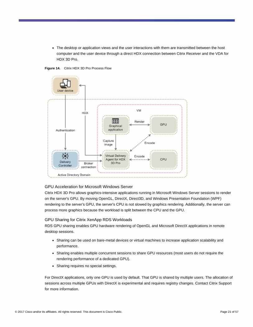
As shown in Figure 14:
● The host computer must reside in the same Microsoft Active Directory domain as the delivery controller.
● When a user logs on to Citrix Receiver and accesses the virtual application or desktop, the controller
authenticates the user and contacts the VDA for HDX 3D Pro to broker a connection to the computer
hosting the graphical application.
● The VDA for HDX 3D Pro uses the appropriate hardware on the host to compress views of the complete
desktop or of just the graphical application.
© 2017 Cisco and/or its affiliates. All rights reserved. This document is Cisco Public. Page 21 of 57
● The desktop or application views and the user interactions with them are transmitted between the host
computer and the user device through a direct HDX connection between Citrix Receiver and the VDA for
HDX 3D Pro.
Figure 14. Citrix HDX 3D Pro Process Flow
GPU Acceleration for Microsoft Windows Server
Citrix HDX 3D Pro allows graphics-intensive applications running in Microsoft Windows Server sessions to render
on the server's GPU. By moving OpenGL, DirectX, Direct3D, and Windows Presentation Foundation (WPF)
rendering to the server's GPU, the server's CPU is not slowed by graphics rendering. Additionally, the server can
process more graphics because the workload is split between the CPU and the GPU.
GPU Sharing for Citrix XenApp RDS Workloads
RDS GPU sharing enables GPU hardware rendering of OpenGL and Microsoft DirectX applications in remote
desktop sessions.
● Sharing can be used on bare-metal devices or virtual machines to increase application scalability and
performance.
● Sharing enables multiple concurrent sessions to share GPU resources (most users do not require the
rendering performance of a dedicated GPU).
● Sharing requires no special settings.
For DirectX applications, only one GPU is used by default. That GPU is shared by multiple users. The allocation of
sessions across multiple GPUs with DirectX is experimental and requires registry changes. Contact Citrix Support
for more information.
© 2017 Cisco and/or its affiliates. All rights reserved. This document is Cisco Public. Page 22 of 57
You can install multiple GPUs on a hypervisor and assign virtual machines to each of these GPUs on a one-to-one
basis: either install a graphics card with more than one GPU, or install multiple graphics cards with one or more
GPUs each. Mixing heterogeneous graphics cards on a server is not recommended.
Virtual machines require direct pass-through access to a GPU, which is available with VMware vSphere 6. When
Citrix HDX 3D Pro is used with GPU pass-through, each GPU in the server supports one multiuser virtual machine.
Scalability using RDS GPU sharing depends on several factors:
● The applications being run
● The amount of video RAM that the applications consume
● The graphics card's processing power
Some applications handle video RAM shortages better than others. If the hardware becomes extremely
overloaded, the system may become unstable, or the graphics card driver may fail. Limit the number of concurrent
users to avoid such problems.
To confirm that GPU acceleration is occurring, use a third-party tool such as GPU-Z. GPU-Z is available at
http://www.techpowerup.com/gpuz/.
Citrix HDX 3D Pro Requirements
The physical or virtual machine hosting the application can use GPU pass-through or vGPU:
● GPU pass-through is available with Citrix XenServer; VMware vSphere and ESX, where it is referred to as
virtual direct graphics acceleration (vDGA); and Microsoft Hyper-V in Microsoft Windows Server 2016,
where it is referred to as discrete device assignment (DDA).
● vGPU is available with Citrix XenServer and VMware vSphere; see https://www.citrix.com/products/xenapp-
xendesktop/hdx-3d-pro.html.
● Citrix recommends that the host computer have at least 4 GB of RAM and four virtual CPUs with a clock
speed of 2.3 GHz or higher.
The requirements for the GPU are as follows:
● For CPU-based compression (including lossless compression), Citrix HDX 3D Pro supports any display
adapter on the host computer that is compatible with the application being delivered.
● For virtualized graphics acceleration using the NVIDIA GRID API, HDX 3D Pro can be used with supported
GRID cards (see NVIDIA GRID). GRID delivers a high frame rate, resulting in a highly interactive user
experience.
● Virtualized graphics acceleration is supported on the Intel Xeon processor E3 family data center graphics
platform. For more information, see http://www.citrix.com/intel and
http://www.intel.com/content/www/us/en/servers/data-center-graphics.html.
© 2017 Cisco and/or its affiliates. All rights reserved. This document is Cisco Public. Page 23 of 57
The requirements for the user device are as follows:
● HDX 3D Pro supports all monitor resolutions that are supported by the GPU on the host computer.
However, for optimal performance with the minimum recommended user device and GPU specifications,
Citrix recommends a maximum monitor resolution for user devices of 1920 x 1200 pixels for LAN
connections, and 1280 x 1024 pixels for WAN connections.
● Citrix recommends that user devices have at least 1 GB of RAM and a CPU with a clock speed of 1.6 GHz
or higher. Use of the default deep compression codec, which is required on low-bandwidth connections,
requires a more powerful CPU unless the decoding is performed in hardware. For optimum performance,
Citrix recommends that user devices have at least 2 GB of RAM and a dual-core CPU with a clock speed of
3 GHz or higher.
● For multiple-monitor access, Citrix recommends user devices with quad-core CPUs.
● User devices do not need a GPU to access desktops or applications delivered with HDX 3D Pro.
● Citrix Receiver must be installed.
For more information, see the Citrix HDX 3D Pro articles at http://docs.citrix.com/en-us/xenapp-and-xendesktop/7-
12/hdx/hdx-3d-pro.html and http://www.citrix.com/xenapp/3.
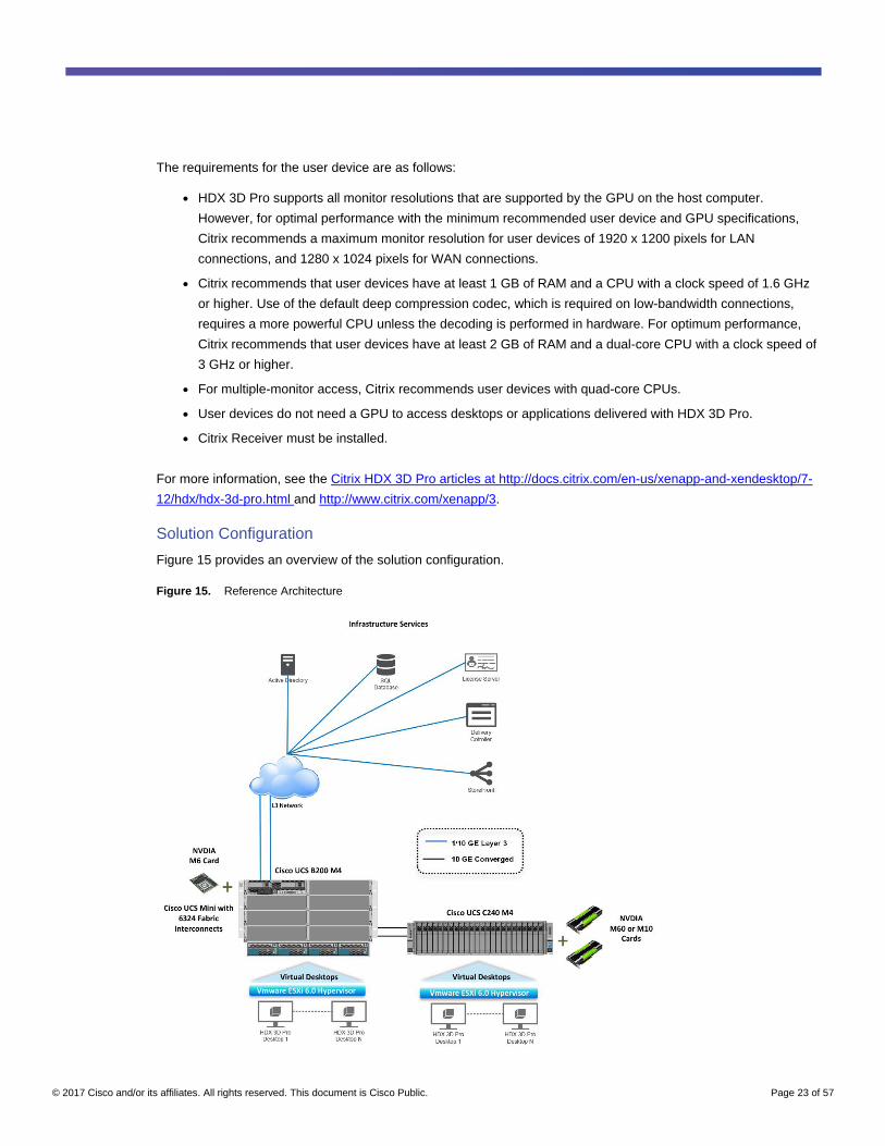
Solution Configuration
Figure 15 provides an overview of the solution configuration.
Figure 15. Reference Architecture
© 2017 Cisco and/or its affiliates. All rights reserved. This document is Cisco Public. Page 24 of 57
The hardware components in the solution are:
● Cisco UCS C240 M4 Rack Server (two Intel Xeon processor E5-2680 v4 CPUs at 2.40 GHz) with 512 GB of
memory (32 GB x 16 DIMMs at 2400 MHz)
● Cisco UCS B200 M4 Blade Server (two Intel Xeon E5-2680 v4 CPUs at 2.60 GHz) with 512 GB of memory
(32 GB x 16 DIMMs at 2400 MHz)
● Cisco UCS VIC 1227/1387 mLOM (Cisco UCS C240 M4)
● Cisco UCS VIC 1340 mLOM (Cisco UCS B200 M4)
● Two Cisco UCS 6324 fabric interconnects in Cisco UCS Mini or UCS second- or third-generation fabric
interconnects
● Twelve 600-GB SAS disks at 10,000 rpm
● NVIDIA Tesla M10, M6, and M60 cards
● Two Cisco Nexus® 9372 Switches (optional access switches)
The software components of the solution are:
● Cisco UCS Firmware Release 3.1(3a)
● VMware ESXi 6.0 (4192238) for VDI hosts
● Citrix XenApp and XenDesktop 7.12
● Microsoft Windows 10 64-bit
● Microsoft Server 2012 R2
● NVIDIA GRID 2.0 software and licenses:
◦ NVIDIA-vGPU-VMware_ESXi_6.0_Host_Driver_367.64-1OEM.600.0.0.2494585
◦ 369.71_grid_win10_server2016_64bit_international
Configure Cisco UCS
This section describes the Cisco UCS configuration.
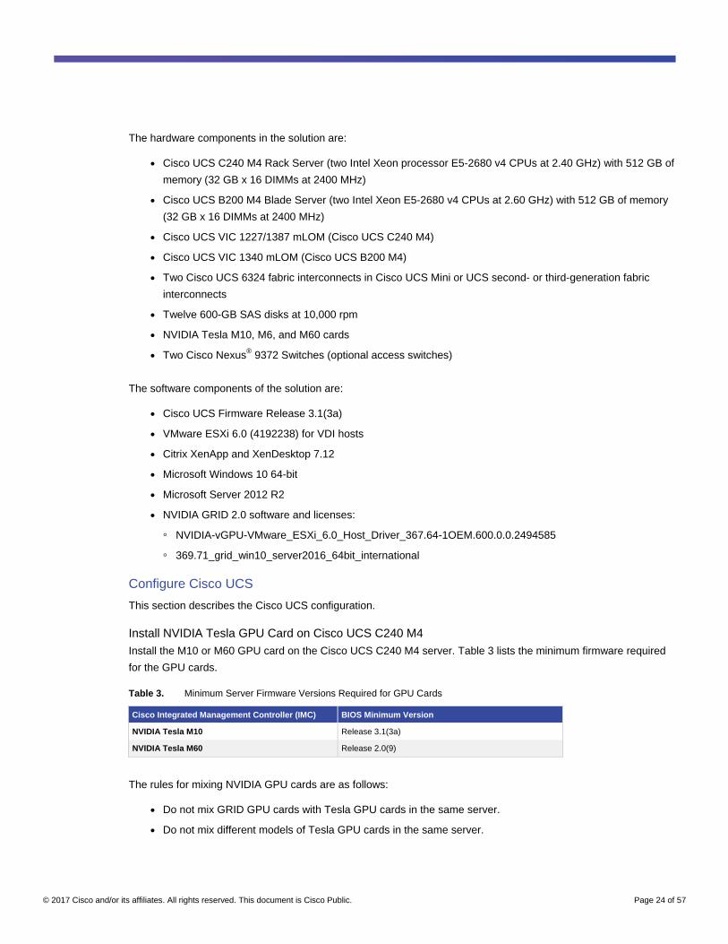
Install NVIDIA Tesla GPU Card on Cisco UCS C240 M4
Install the M10 or M60 GPU card on the Cisco UCS C240 M4 server. Table 3 lists the minimum firmware required
for the GPU cards.
Table 3. Minimum Server Firmware Versions Required for GPU Cards
Cisco Integrated Management Controller (IMC) BIOS Minimum Version
NVIDIA Tesla M10 Release 3.1(3a)
NVIDIA Tesla M60 Release 2.0(9)
The rules for mixing NVIDIA GPU cards are as follows:
● Do not mix GRID GPU cards with Tesla GPU cards in the same server.
● Do not mix different models of Tesla GPU cards in the same server.
© 2017 Cisco and/or its affiliates. All rights reserved. This document is Cisco Public. Page 25 of 57
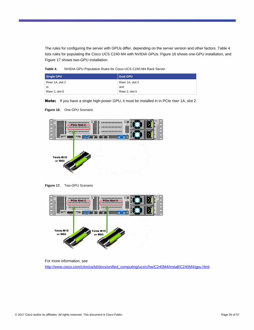
The rules for configuring the server with GPUs differ, depending on the server version and other factors. Table 4
lists rules for populating the Cisco UCS C240 M4 with NVIDIA GPUs. Figure 16 shows one-GPU installation, and
Figure 17 shows two-GPU installation.
Table 4. NVIDIA GPU Population Rules for Cisco UCS C240 M4 Rack Server
Single GPU Dual GPU
Riser 1A, slot 2
or
Riser 2, slot 5
Riser 1A, slot 2
and
Riser 2, slot 5
Note: If you have a single high-power GPU, it must be installed in in PCIe riser 1A, slot 2.
Figure 16. One-GPU Scenario
Figure 17. Two-GPU Scenario
For more information, see
http://www.cisco.com/c/en/us/td/docs/unified_computing/ucs/c/hw/C240M4/install/C240M4/gpu.html.
© 2017 Cisco and/or its affiliates. All rights reserved. This document is Cisco Public. Page 26 of 57
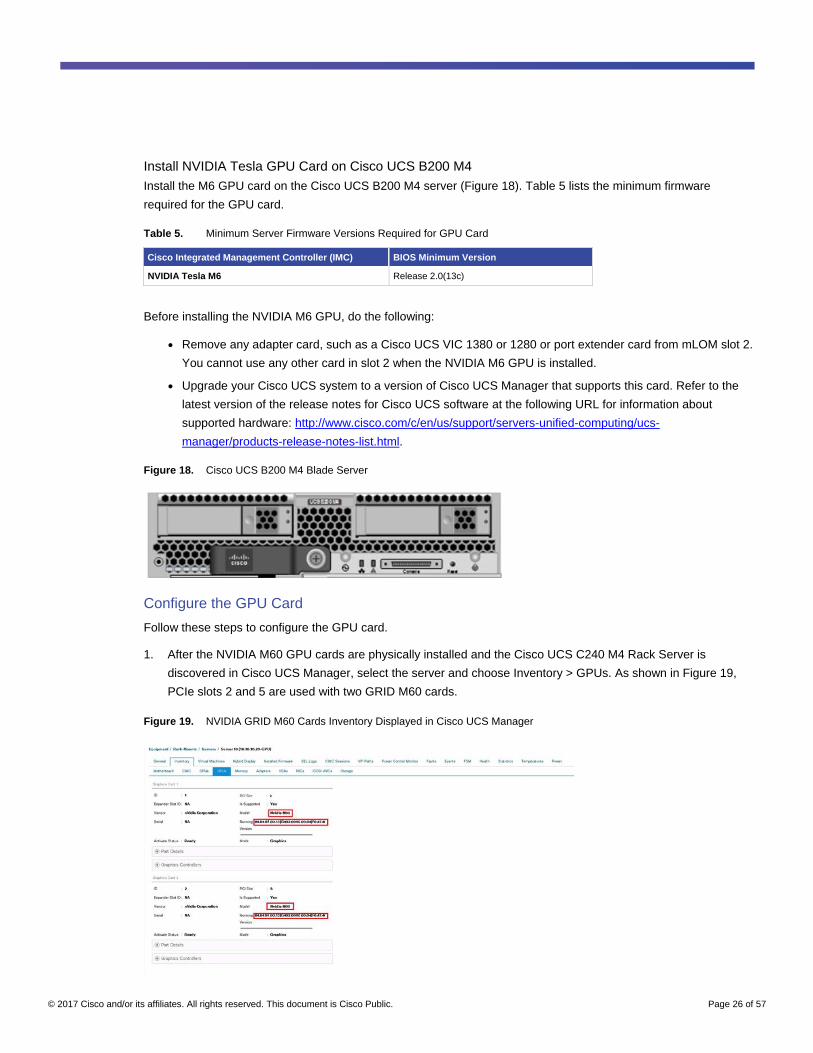
Install NVIDIA Tesla GPU Card on Cisco UCS B200 M4
Install the M6 GPU card on the Cisco UCS B200 M4 server (Figure 18). Table 5 lists the minimum firmware
required for the GPU card.
Table 5. Minimum Server Firmware Versions Required for GPU Card
Cisco Integrated Management Controller (IMC) BIOS Minimum Version
NVIDIA Tesla M6 Release 2.0(13c)
Before installing the NVIDIA M6 GPU, do the following:
● Remove any adapter card, such as a Cisco UCS VIC 1380 or 1280 or port extender card from mLOM slot 2.
You cannot use any other card in slot 2 when the NVIDIA M6 GPU is installed.
● Upgrade your Cisco UCS system to a version of Cisco UCS Manager that supports this card. Refer to the
latest version of the release notes for Cisco UCS software at the following URL for information about
supported hardware: http://www.cisco.com/c/en/us/support/servers-unified-computing/ucs-
manager/products-release-notes-list.html.
Figure 18. Cisco UCS B200 M4 Blade Server
Configure the GPU Card
Follow these steps to configure the GPU card.
1. After the NVIDIA M60 GPU cards are physically installed and the Cisco UCS C240 M4 Rack Server is
discovered in Cisco UCS Manager, select the server and choose Inventory > GPUs. As shown in Figure 19,
PCIe slots 2 and 5 are used with two GRID M60 cards.
Figure 19. NVIDIA GRID M60 Cards Inventory Displayed in Cisco UCS Manager

© 2017 Cisco and/or its affiliates. All rights reserved. This document is Cisco Public. Page 27 of 57
2. After the NVIDIA M10 GPU cards are physically installed and the Cisco UCS C240 M4 Rack Server is
discovered in Cisco UCS Manager, select the server and choose Inventory > GPUs. As shown in Figure 20,
PCIe slot 2 used with GRID M10 card.
Figure 20. NVIDIA GRID M10 Cards Inventory Displayed in Cisco UCS Manager.
3. After the NVIDIA M6 GPU card is physically installed and the Cisco UCS B200 M4 Blade Server is discovered
in Cisco UCS Manager, select the server and choose Inventory > GPUs. As shown in Figure 21, PCIe slot 2 is
used with the GRID M6 card.
Figure 21. NVIDIA GRID Cards Inventory Displayed in Cisco UCS Manager
You can use Cisco UCS Manager to perform firmware upgrades to the NVIDIA GPU cards in managed Cisco UCS
C240 M4 servers.
Note: VMware ESX virtual machine hardware Version 9 or later is required for vGPU and vDGA configuration.
Virtual machines with hardware Version 9 or later should have their settings managed through the VMware
vSphere Web Client.

© 2017 Cisco and/or its affiliates. All rights reserved. This document is Cisco Public. Page 28 of 57
Install the NVIDIA GRID Software
Three packages are required for VMware ESXi host setup, as shown in Figure 22:
● The GRID license server installer
● The NVIDIA GRID Manager software, which is installed on VMware vSphere ESXi; the NVIDIA drivers and
software that are installed in Microsoft Windows are also in this folder
● The GPU Mode Switch utility, which changes the cards from the default Compute mode to Graphics mode
Figure 22. Software Required for NVIDIA GRID 2.0 Setup on the VMware ESXi Host
Install the NVIDIA GRID License Server
The NVIDIA GRID vGPU is a licensed feature on Tesla M6, M10, and M60 cards. A software license is required to
use the full vGPU features on a guest virtual machine. An NVIDIA license server with the appropriate licenses is
required.
This section summarizes the installation and configuration process for the NVIDIA GRID 2.0 license server.
To get an evaluation license code and download the software, register at http://www.nvidia.com/grid-evaluation.
The steps shown here use the Microsoft Windows version of the license server installed on Windows Server 2012
R2. A Linux version of the license server is also available.
The GRID 2.0 license server requires Java Version 7 or later. Go to Java.com and install the latest version.
1. Extract and open the NVIDIA-ls-windows-2015.12-0001 folder. Run setup.exe (Figure 23).
Figure 23. Run setup.exe
2. Click Next (Figure 24).

© 2017 Cisco and/or its affiliates. All rights reserved. This document is Cisco Public. Page 29 of 57
Figure 24. NVIDIA License Server
3. Accept the license agreement and click Next (Figure 25).
Figure 25. NVIDIA License Agreement
© 2017 Cisco and/or its affiliates. All rights reserved. This document is Cisco Public. Page 30 of 57
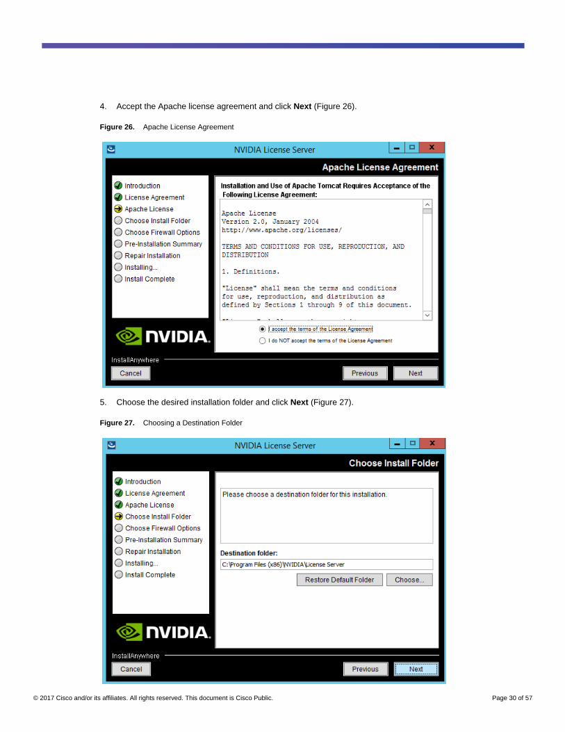
4. Accept the Apache license agreement and click Next (Figure 26).
Figure 26. Apache License Agreement
5. Choose the desired installation folder and click Next (Figure 27).
Figure 27. Choosing a Destination Folder
© 2017 Cisco and/or its affiliates. All rights reserved. This document is Cisco Public. Page 31 of 57
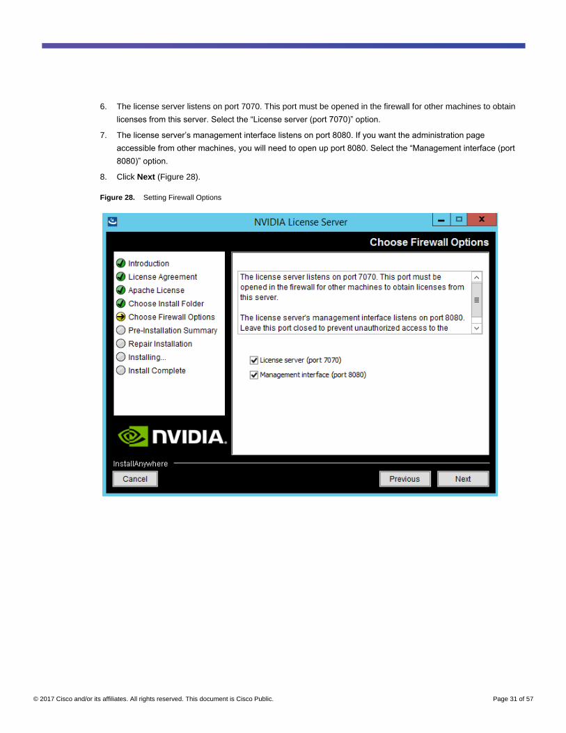
6. The license server listens on port 7070. This port must be opened in the firewall for other machines to obtain
licenses from this server. Select the “License server (port 7070)” option.
7. The license server’s management interface listens on port 8080. If you want the administration page
accessible from other machines, you will need to open up port 8080. Select the “Management interface (port
8080)” option.
8. Click Next (Figure 28).
Figure 28. Setting Firewall Options
© 2017 Cisco and/or its affiliates. All rights reserved. This document is Cisco Public. Page 32 of 57
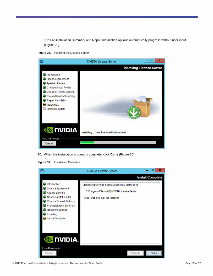
9. The Pre-installation Summary and Repair Installation options automatically progress without user input
(Figure 29).
Figure 29. Installing the License Server
10. When the installation process is complete, click Done (Figure 30).
Figure 30. Installation Complete

© 2017 Cisco and/or its affiliates. All rights reserved. This document is Cisco Public. Page 33 of 57
Configure the NVIDIA GRID 2.0 License Server
Now configure the NVIDIA Grid license server.
1. Log in to the license server site with the credentials set up during the registration process at
nvidia.com/grideval. A license file is generated from https://nvidia.flexnetoperations.com.
2. After you are logged in, click Create License Server.
3. Specify the fields as shown in Figure 31. In the License Server ID field, enter the MAC address of your local
license server’s NIC. Leave the ID Type set to Ethernet. For the Alias and Site Name, choose user-friendly
names. Then click Create.
Figure 31. Creating the License Server
4. Click the Search License Servers node.
5. Click your license server ID (Figure 32).
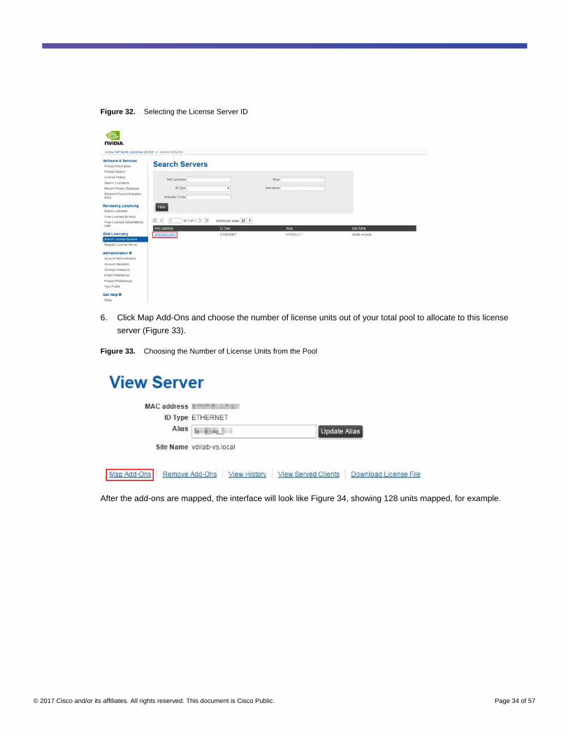
© 2017 Cisco and/or its affiliates. All rights reserved. This document is Cisco Public. Page 34 of 57
Figure 32. Selecting the License Server ID
6. Click Map Add-Ons and choose the number of license units out of your total pool to allocate to this license
server (Figure 33).
Figure 33. Choosing the Number of License Units from the Pool
After the add-ons are mapped, the interface will look like Figure 34, showing 128 units mapped, for example.
© 2017 Cisco and/or its affiliates. All rights reserved. This document is Cisco Public. Page 35 of 57
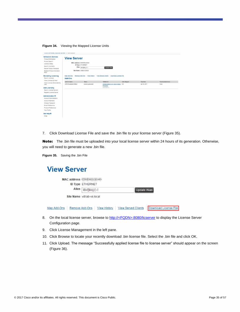
Figure 34. Viewing the Mapped License Units
7. Click Download License File and save the .bin file to your license server (Figure 35).
Note: The .bin file must be uploaded into your local license server within 24 hours of its generation. Otherwise,
you will need to generate a new .bin file.
Figure 35. Saving the .bin File
8. On the local license server, browse to http://<FQDN>:8080/licserver to display the License Server
Configuration page.
9. Click License Management in the left pane.
10. Click Browse to locate your recently download .bin license file. Select the .bin file and click OK.
11. Click Upload. The message “Successfully applied license file to license server” should appear on the screen
(Figure 36).
© 2017 Cisco and/or its affiliates. All rights reserved. This document is Cisco Public. Page 36 of 57
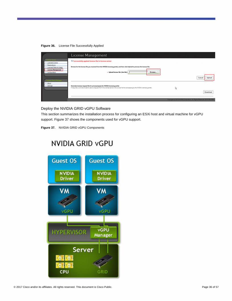
Figure 36. License File Successfully Applied
Deploy the NVIDIA GRID vGPU Software
This section summarizes the installation process for configuring an ESXi host and virtual machine for vGPU
support. Figure 37 shows the components used for vGPU support.
Figure 37. NVIDIA GRID vGPU Components
© 2017 Cisco and/or its affiliates. All rights reserved. This document is Cisco Public. Page 37 of 57
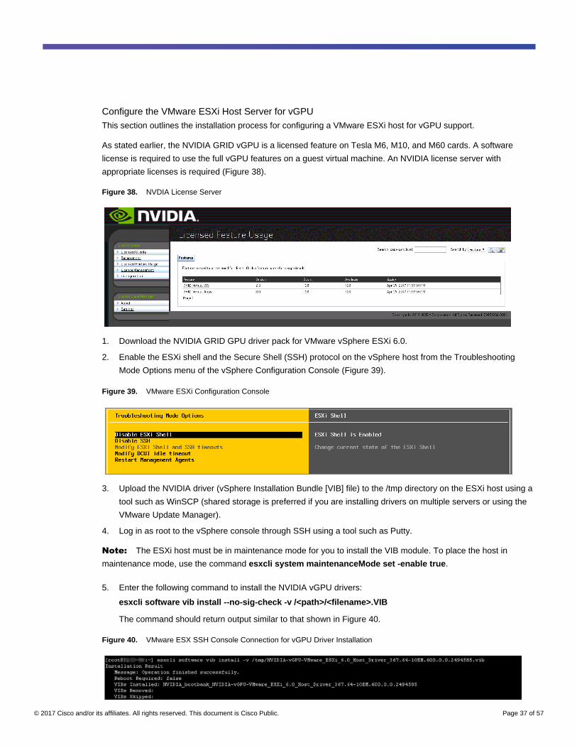
Configure the VMware ESXi Host Server for vGPU
This section outlines the installation process for configuring a VMware ESXi host for vGPU support.
As stated earlier, the NVIDIA GRID vGPU is a licensed feature on Tesla M6, M10, and M60 cards. A software
license is required to use the full vGPU features on a guest virtual machine. An NVIDIA license server with
appropriate licenses is required (Figure 38).
Figure 38. NVDIA License Server
1. Download the NVIDIA GRID GPU driver pack for VMware vSphere ESXi 6.0.
2. Enable the ESXi shell and the Secure Shell (SSH) protocol on the vSphere host from the Troubleshooting
Mode Options menu of the vSphere Configuration Console (Figure 39).
Figure 39. VMware ESXi Configuration Console
3. Upload the NVIDIA driver (vSphere Installation Bundle [VIB] file) to the /tmp directory on the ESXi host using a
tool such as WinSCP (shared storage is preferred if you are installing drivers on multiple servers or using the
VMware Update Manager).
4. Log in as root to the vSphere console through SSH using a tool such as Putty.
Note: The ESXi host must be in maintenance mode for you to install the VIB module. To place the host in
maintenance mode, use the command esxcli system maintenanceMode set -enable true.
5. Enter the following command to install the NVIDIA vGPU drivers:
esxcli software vib install --no-sig-check -v /<path>/<filename>.VIB
The command should return output similar to that shown in Figure 40.
Figure 40. VMware ESX SSH Console Connection for vGPU Driver Installation

© 2017 Cisco and/or its affiliates. All rights reserved. This document is Cisco Public. Page 38 of 57
Note: Although the display shows Reboot Required: false, a reboot is necessary for the VIB file to load and for
xorg to start.
6. Exit the ESXi host from maintenance mode and reboot the host by using the vSphere Web Client or by
entering the following commands:
esxcli system maintenanceMode set -e false
reboot
7. After the host reboots successfully, verify that the kernel module has loaded successfully using the following
command:
esxcli software vib list | grep -i nvidia
The command should return output similar to that shown in Figure 41.
Figure 41. VMware ESX SSH Console Connection for Driver Verification
Note: See the VMware knowledge base article for information about removing any existing NVIDIA drivers
before installing new drivers:
http://kb.vmware.com/selfservice/microsites/search.do?language=en_US&cmd=displayKC&externalId=2033434.
8. Confirm GRID GPU detection on the ESXi host. To determine the status of the GPU card’s CPU, the card’s
memory, and the amount of disk space remaining on the card, enter the following command:
nvidia-smi
The command should return output similar to Figures 42, 43, or 44, depending on the cards used in your
environment.
Figure 42. VMware ESX SSH Console Connection for GPU M60 Card Detection

© 2017 Cisco and/or its affiliates. All rights reserved. This document is Cisco Public. Page 39 of 57
Figure 43. VMware ESX SSH Console Connection for GPU M10 Card Detection
Figure 44. VMware ESX SSH Console Connection for GPU M6 Card Detection
Note: The NVIDIA system management interface (SMI) also allows GPU monitoring using the following
command (this command adds a loop, automatically refreshing the display): nvidia-smi –l.
© 2017 Cisco and/or its affiliates. All rights reserved. This document is Cisco Public. Page 40 of 57
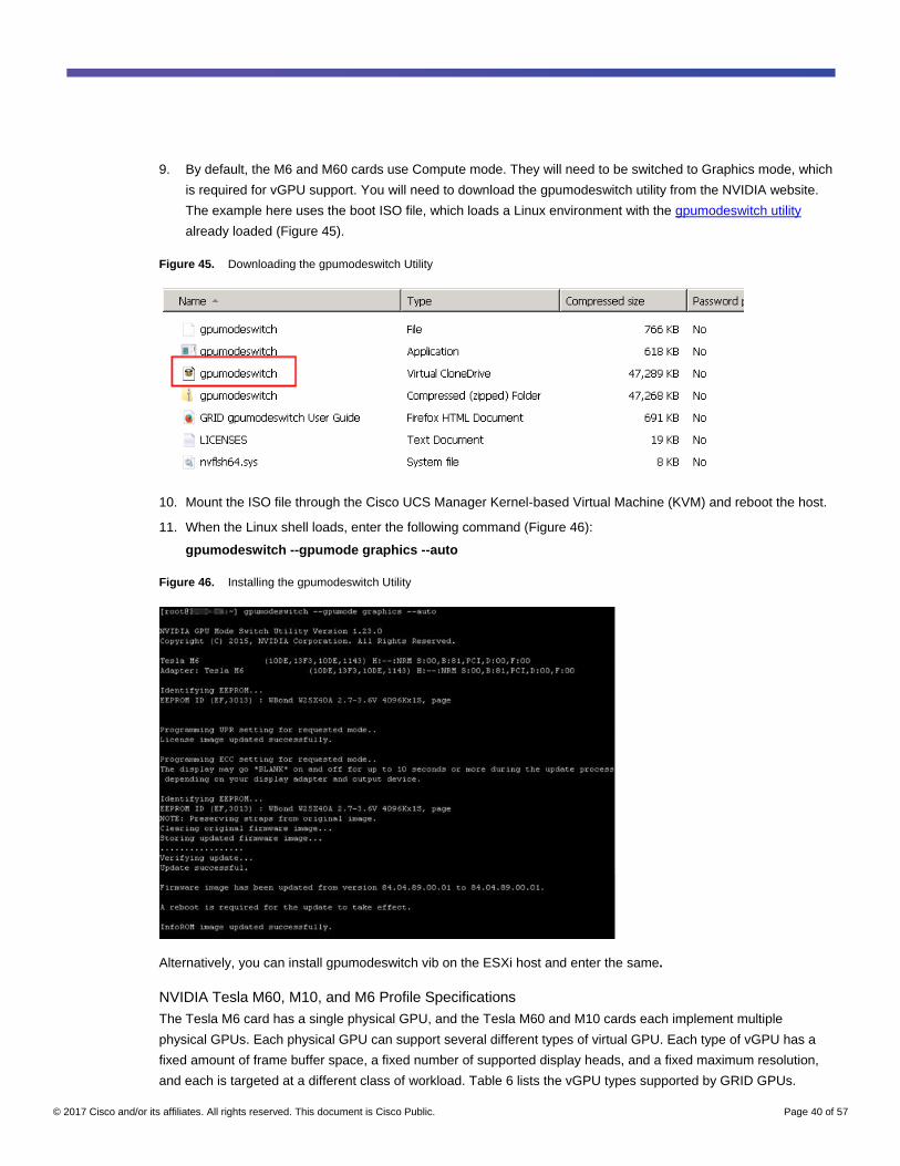
9. By default, the M6 and M60 cards use Compute mode. They will need to be switched to Graphics mode, which
is required for vGPU support. You will need to download the gpumodeswitch utility from the NVIDIA website.
The example here uses the boot ISO file, which loads a Linux environment with the gpumodeswitch utility
already loaded (Figure 45).
Figure 45. Downloading the gpumodeswitch Utility
10. Mount the ISO file through the Cisco UCS Manager Kernel-based Virtual Machine (KVM) and reboot the host.
11. When the Linux shell loads, enter the following command (Figure 46):
gpumodeswitch --gpumode graphics --auto
Figure 46. Installing the gpumodeswitch Utility
Alternatively, you can install gpumodeswitch vib on the ESXi host and enter the same.
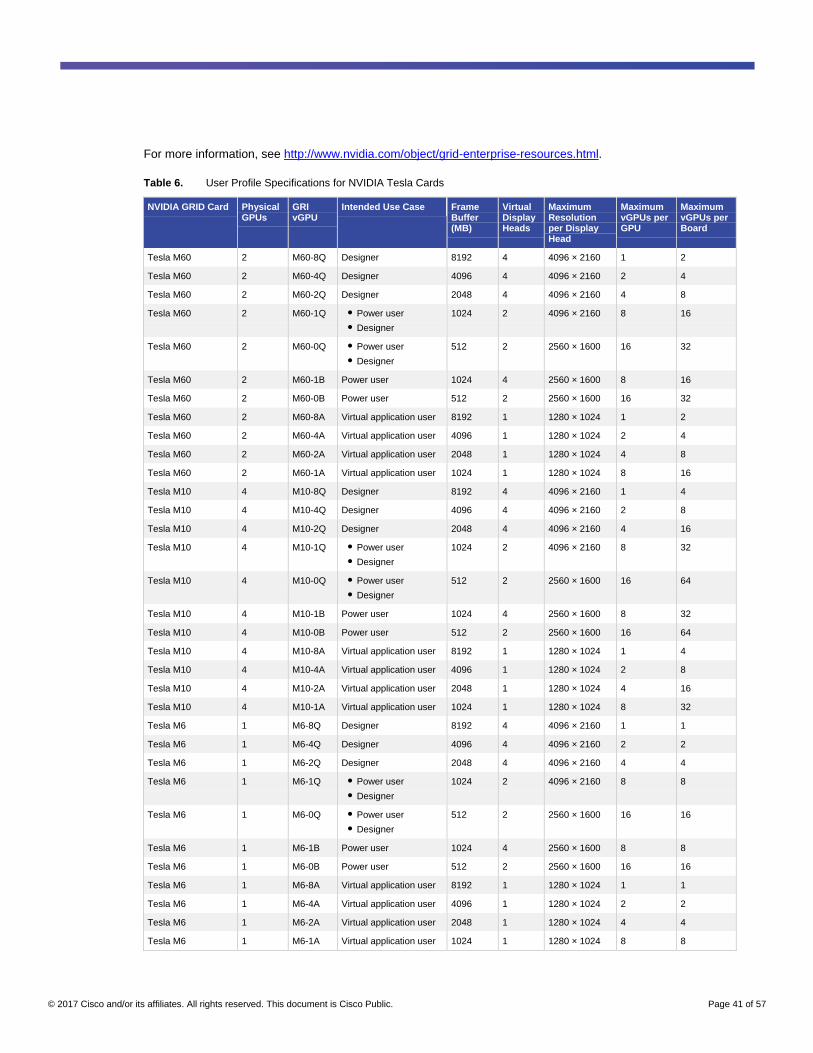
NVIDIA Tesla M60, M10, and M6 Profile Specifications
The Tesla M6 card has a single physical GPU, and the Tesla M60 and M10 cards each implement multiple
physical GPUs. Each physical GPU can support several different types of virtual GPU. Each type of vGPU has a
fixed amount of frame buffer space, a fixed number of supported display heads, and a fixed maximum resolution,
and each is targeted at a different class of workload. Table 6 lists the vGPU types supported by GRID GPUs.
© 2017 Cisco and/or its affiliates. All rights reserved. This document is Cisco Public. Page 41 of 57
For more information, see http://www.nvidia.com/object/grid-enterprise-resources.html.
Table 6. User Profile Specifications for NVIDIA Tesla Cards
NVIDIA GRID Card Physical GPUs
GRI vGPU
Intended Use Case Frame Buffer (MB)
Virtual Display Heads
Maximum Resolution per Display Head
Maximum vGPUs per GPU
Maximum vGPUs per Board
Tesla M60 2 M60-8Q Designer 8192 4 4096 × 2160 1 2
Tesla M60 2 M60-4Q Designer 4096 4 4096 × 2160 2 4
Tesla M60 2 M60-2Q Designer 2048 4 4096 × 2160 4 8
Tesla M60 2 M60-1Q ● Power user
● Designer
1024 2 4096 × 2160 8 16
Tesla M60 2 M60-0Q ● Power user
● Designer
512 2 2560 × 1600 16 32
Tesla M60 2 M60-1B Power user 1024 4 2560 × 1600 8 16
Tesla M60 2 M60-0B Power user 512 2 2560 × 1600 16 32
Tesla M60 2 M60-8A Virtual application user 8192 1 1280 × 1024 1 2
Tesla M60 2 M60-4A Virtual application user 4096 1 1280 × 1024 2 4
Tesla M60 2 M60-2A Virtual application user 2048 1 1280 × 1024 4 8
Tesla M60 2 M60-1A Virtual application user 1024 1 1280 × 1024 8 16
Tesla M10 4 M10-8Q Designer 8192 4 4096 × 2160 1 4
Tesla M10 4 M10-4Q Designer 4096 4 4096 × 2160 2 8
Tesla M10 4 M10-2Q Designer 2048 4 4096 × 2160 4 16
Tesla M10 4 M10-1Q ● Power user
● Designer
1024 2 4096 × 2160 8 32
Tesla M10 4 M10-0Q ● Power user
● Designer
512 2 2560 × 1600 16 64
Tesla M10 4 M10-1B Power user 1024 4 2560 × 1600 8 32
Tesla M10 4 M10-0B Power user 512 2 2560 × 1600 16 64
Tesla M10 4 M10-8A Virtual application user 8192 1 1280 × 1024 1 4
Tesla M10 4 M10-4A Virtual application user 4096 1 1280 × 1024 2 8
Tesla M10 4 M10-2A Virtual application user 2048 1 1280 × 1024 4 16
Tesla M10 4 M10-1A Virtual application user 1024 1 1280 × 1024 8 32
Tesla M6 1 M6-8Q Designer 8192 4 4096 × 2160 1 1
Tesla M6 1 M6-4Q Designer 4096 4 4096 × 2160 2 2
Tesla M6 1 M6-2Q Designer 2048 4 4096 × 2160 4 4
Tesla M6 1 M6-1Q ● Power user
● Designer
1024 2 4096 × 2160 8 8
Tesla M6 1 M6-0Q ● Power user
● Designer
512 2 2560 × 1600 16 16
Tesla M6 1 M6-1B Power user 1024 4 2560 × 1600 8 8
Tesla M6 1 M6-0B Power user 512 2 2560 × 1600 16 16
Tesla M6 1 M6-8A Virtual application user 8192 1 1280 × 1024 1 1
Tesla M6 1 M6-4A Virtual application user 4096 1 1280 × 1024 2 2
Tesla M6 1 M6-2A Virtual application user 2048 1 1280 × 1024 4 4
Tesla M6 1 M6-1A Virtual application user 1024 1 1280 × 1024 8 8
© 2017 Cisco and/or its affiliates. All rights reserved. This document is Cisco Public. Page 42 of 57
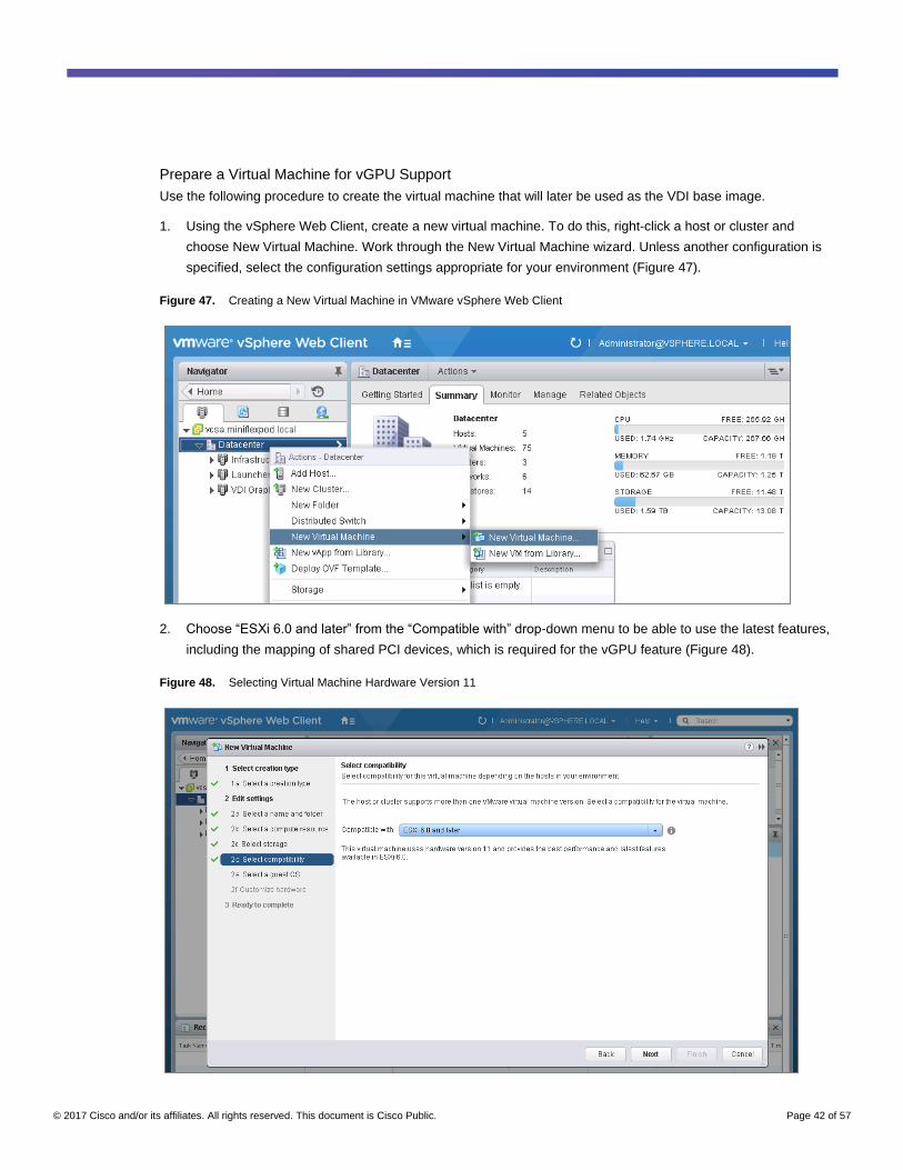
Prepare a Virtual Machine for vGPU Support
Use the following procedure to create the virtual machine that will later be used as the VDI base image.
1. Using the vSphere Web Client, create a new virtual machine. To do this, right-click a host or cluster and
choose New Virtual Machine. Work through the New Virtual Machine wizard. Unless another configuration is
specified, select the configuration settings appropriate for your environment (Figure 47).
Figure 47. Creating a New Virtual Machine in VMware vSphere Web Client
2. Choose “ESXi 6.0 and later” from the “Compatible with” drop-down menu to be able to use the latest features,
including the mapping of shared PCI devices, which is required for the vGPU feature (Figure 48).
Figure 48. Selecting Virtual Machine Hardware Version 11
© 2017 Cisco and/or its affiliates. All rights reserved. This document is Cisco Public. Page 43 of 57
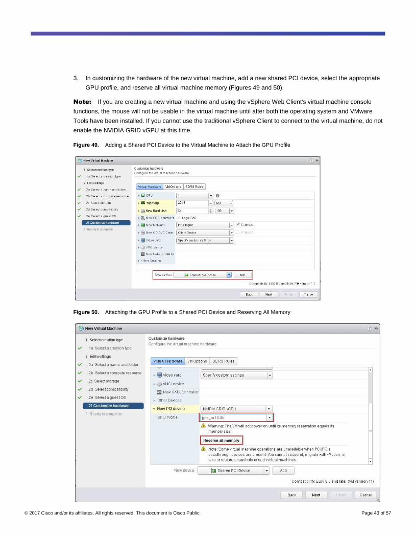
3. In customizing the hardware of the new virtual machine, add a new shared PCI device, select the appropriate
GPU profile, and reserve all virtual machine memory (Figures 49 and 50).
Note: If you are creating a new virtual machine and using the vSphere Web Client's virtual machine console
functions, the mouse will not be usable in the virtual machine until after both the operating system and VMware
Tools have been installed. If you cannot use the traditional vSphere Client to connect to the virtual machine, do not
enable the NVIDIA GRID vGPU at this time.
Figure 49. Adding a Shared PCI Device to the Virtual Machine to Attach the GPU Profile
Figure 50. Attaching the GPU Profile to a Shared PCI Device and Reserving All Memory
© 2017 Cisco and/or its affiliates. All rights reserved. This document is Cisco Public. Page 44 of 57
4. Install and configure Microsoft Windows on the virtual machine:
a. Configure the virtual machine with the appropriate amount of vCPU and RAM according to the GPU profile
selected.
b. Install VMware Tools.
c. Join the virtual machine to the Microsoft Active Directory domain.
d. Choose “Allow remote connections to this computer” on the Windows System Properties menu.
Install the NVIDIA vGPU Software Driver and Citrix HDX 3D Pro Agent
Use the following procedure to install the NVIDIA GRID vGPU drivers on the desktop virtual machine and to install
the HDX 3D Pro Virtual Desktop Agent to prepare this virtual machine to be managed by the XenDesktop
controller. To fully enable vGPU operation, the NVIDIA driver must be installed.
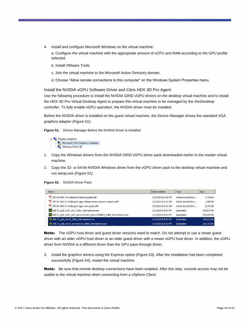
Before the NVIDIA driver is installed on the guest virtual machine, the Device Manager shows the standard VGA
graphics adapter (Figure 51).
Figure 51. Device Manager Before the NVIDIA Driver Is Installed
1. Copy the Windows drivers from the NVIDIA GRID vGPU driver pack downloaded earlier to the master virtual
machine.
2. Copy the 32- or 64-bit NVIDIA Windows driver from the vGPU driver pack to the desktop virtual machine and
run setup.exe (Figure 52).
Figure 52. NVIDIA Driver Pack
Note: The vGPU host driver and guest driver versions need to match. Do not attempt to use a newer guest
driver with an older vGPU host driver or an older guest driver with a newer vGPU host driver. In addition, the vGPU
driver from NVIDIA is a different driver than the GPU pass-through driver.
3. Install the graphics drivers using the Express option (Figure 53). After the installation has been completed
successfully (Figure 54), restart the virtual machine.
Note: Be sure that remote desktop connections have been enabled. After this step, console access may not be
usable to the virtual machine when connecting from a vSphere Client.

© 2017 Cisco and/or its affiliates. All rights reserved. This document is Cisco Public. Page 45 of 57
Figure 53. Selecting the Express Installation Option
Figure 54. Express Installation Complete
4. To start the HDX 3D Pro VDA installation, mount the XenApp and XenDesktop 7.12 or later ISO image on the
virtual machine or copy the Feature Pack VDA installation media to the virtual desktop virtual machine.
5. Install Citrix XenDesktop HDX 3D Pro Virtual Desktop Agent (Figure 55). Reboot when prompted to do so.

© 2017 Cisco and/or its affiliates. All rights reserved. This document is Cisco Public. Page 46 of 57
Figure 55. Citrix XenDesktop Virtual Delivery Agent Installation Setup
6. Reboot the virtual machine after the VDA for HDX 3D Pro has been installed successfully (Figure 56).
Figure 56. Successful Installation of the Virtual Delivery Agent
7. After the HDX 3D Pro Virtual Desktop Agent has been installed and the virtual machine rebooted successfully,
install the graphics applications, benchmark tools, and sample models that you want to deliver to all users.
Refer to this blog for a list of graphics tools that you can use for evaluation and testing purposes:
http://blogs.citrix.com/2014/08/13/citrix-hdx-the-big-list-of-graphical-benchmarks-tools-and-demos/.
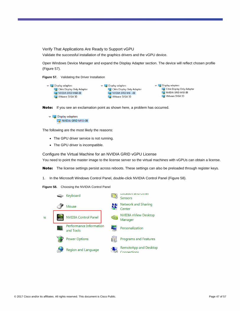
© 2017 Cisco and/or its affiliates. All rights reserved. This document is Cisco Public. Page 47 of 57
Verify That Applications Are Ready to Support vGPU
Validate the successful installation of the graphics drivers and the vGPU device.
Open Windows Device Manager and expand the Display Adapter section. The device will reflect chosen profile
(Figure 57).
Figure 57. Validating the Driver Installation
Note: If you see an exclamation point as shown here, a problem has occurred.
The following are the most likely the reasons:
● The GPU driver service is not running.
● The GPU driver is incompatible.
Configure the Virtual Machine for an NVIDIA GRID vGPU License
You need to point the master image to the license server so the virtual machines with vGPUs can obtain a license.
Note: The license settings persist across reboots. These settings can also be preloaded through register keys.
1. In the Microsoft Windows Control Panel, double-click NVIDIA Control Panel (Figure 58).
Figure 58. Choosing the NVIDIA Control Panel
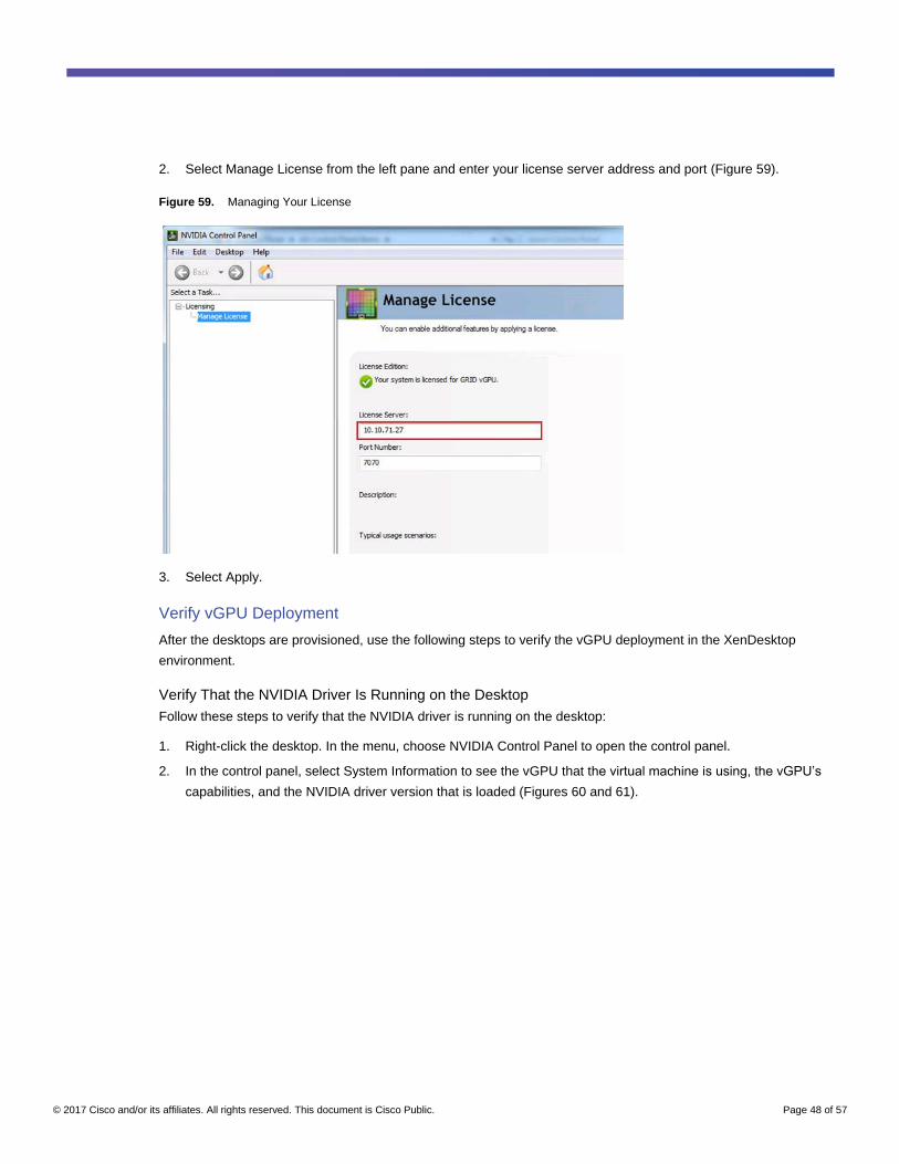
© 2017 Cisco and/or its affiliates. All rights reserved. This document is Cisco Public. Page 48 of 57
2. Select Manage License from the left pane and enter your license server address and port (Figure 59).
Figure 59. Managing Your License
3. Select Apply.
Verify vGPU Deployment
After the desktops are provisioned, use the following steps to verify the vGPU deployment in the XenDesktop
environment.
Verify That the NVIDIA Driver Is Running on the Desktop
Follow these steps to verify that the NVIDIA driver is running on the desktop:
1. Right-click the desktop. In the menu, choose NVIDIA Control Panel to open the control panel.
2. In the control panel, select System Information to see the vGPU that the virtual machine is using, the vGPU’s
capabilities, and the NVIDIA driver version that is loaded (Figures 60 and 61).

© 2017 Cisco and/or its affiliates. All rights reserved. This document is Cisco Public. Page 49 of 57
Figure 60. NVIDIA Control Panel
Figure 61. Verifying Settings
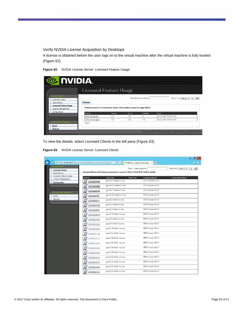
© 2017 Cisco and/or its affiliates. All rights reserved. This document is Cisco Public. Page 50 of 57
Verify NVDIA License Acquisition by Desktops
A license is obtained before the user logs on to the virtual machine after the virtual machine is fully booted
(Figure 62).
Figure 62. NVDIA License Server: Licensed Feature Usage
To view the details, select Licensed Clients in the left pane (Figure 63).
Figure 63. NVDIA License Server: Licensed Clients

© 2017 Cisco and/or its affiliates. All rights reserved. This document is Cisco Public. Page 51 of 57
Verify the NVDIA Configuration on the Host
To obtain a hostwide overview of the NVIDIA GPUs, enter the nvidia-smi command without any arguments
(Figure 64).
Figure 64. The nvdia-smi Command Output from the Host with Two NVIDIA Tesla M10 Cards and 128 Citrix HDX 3D Pro Microsoft Windows 10 Desktops with M10-0B vGPU Profile
© 2017 Cisco and/or its affiliates. All rights reserved. This document is Cisco Public. Page 52 of 57

© 2017 Cisco and/or its affiliates. All rights reserved. This document is Cisco Public. Page 53 of 57
Additional Configurations
This section presents additional configuration options detailed in Citrix product documentation.
Install Citrix HDX 3D Pro Virtual Desktop Agent Using the CLI
When you use the installer's GUI to install a VDA for a Windows desktop, simply select Yes on the HDX 3D Pro
page. When you use the CLI, include the /enable_hdx_3d_pro option with the XenDesktop VdaSetup.exe
command.
To upgrade HDX 3D Pro, uninstall both the separate HDX 3D for Professional Graphics component and the VDA
before installing the VDA for HDX 3D Pro. Similarly, to switch from the standard VDA for a Windows desktop to the
HDX 3D Pro VDA, uninstall the standard VDA and then install the VDA for HDX 3D Pro.
Install and Upgrade NVIDIA Drivers
The NVIDIA GRID API provides direct access to the frame buffer of the GPU, providing the fastest possible frame
rate for a smooth and interactive user experience. If you install NVIDIA drivers before you install a VDA with HDX
3D Pro, NVIDIA GRID is enabled by default.
To enable GRID on a virtual machine, disable Microsoft Basic Display Adapter from the Device Manager. Run the
following command:

© 2017 Cisco and/or its affiliates. All rights reserved. This document is Cisco Public. Page 54 of 57
Montereyenable.exe -enable -noreset
Then restart the VDA.
If you install NVIDIA drivers after you install a VDA with HDX 3D Pro, GRID is disabled. Enable GRID by using the
MontereyEnable tool provided by NVIDIA.
To disable GRID, run the following command:
Montereyenable.exe -disable –noreset
Then restart the VDA.
Use Citrix HDX Monitor
Use the Citrix HDX Monitor tool (which replaces the Health Check tool) to validate the operation and configuration
of HDX visualization technology and to diagnose and troubleshoot HDX problems. To download the tool and learn
more about it, go to https://taas.citrix.com/hdx/download/.
Optimize the Citrix HDX 3D Pro User Experience
To use HDX 3D Pro with multiple monitors, be sure that the host computer is configured with at least as many
monitors as are attached to user devices. The monitors attached to the host computer can be either physical or
virtual.
Do not attach a monitor (either physical or virtual) to a host computer while a user is connected to the virtual
desktop or the application providing the graphical application. Doing so can cause instability for the duration of a
user's session.
Let your users know that changes to the desktop resolution (by them or an application) are not supported while a
graphical application session is running. After closing the application session, a user can change the resolution of
the Desktop Viewer window in Citrix Receiver Desktop Viewer Preferences.
When multiple users share a connection with limited bandwidth (for example, at a branch office), Citrix
recommends that you use the “Overall session bandwidth limit” policy setting to limit the bandwidth available to
each user. This setting helps ensure that the available bandwidth does not fluctuate widely as users log on and off.
Because HDX 3D Pro automatically adjusts to make use of all the available bandwidth, large variations in the
available bandwidth over the course of user sessions can negatively affect performance.
For example, if 20 users share a 60-Mbps connection, the bandwidth available to each user can vary between 3
Mbps and 60 Mbps, depending on the number of concurrent users. To optimize the user experience in this
scenario, determine the bandwidth required per user at peak periods and limit users to this amount at all times.
For users of a 3D mouse, Citrix recommends that you increase the priority of the generic USB redirection virtual
channel to 0. For information about changing the virtual channel priority, see Citrix article CTX128190.
Use GPU Acceleration for Microsoft Windows Server DirectX, Direct3D, and WPF Rendering
DirectX, Direct3D, and WPF rendering is available only on servers with a GPU that supports display driver interface
(DDI) Version 9ex, 10, or 11.
● On Windows Server 2008 R2, DirectX and Direct3D require no special settings to use a single GPU.
● On Windows Server 2012, RDS sessions on the remote desktop session host server use the Microsoft
Basic Render driver as the default adapter. To use the GPU in RDS sessions on Windows Server 2012,

© 2017 Cisco and/or its affiliates. All rights reserved. This document is Cisco Public. Page 55 of 57
enable the “Use the hardware default graphics adapter for all Remote Desktop Services sessions” setting in
the group policy by choosing Local Computer Policy > Computer Configuration > Administrative Templates
> Windows Components > Remote Desktop Services > Remote Desktop Session Host > Remote Session
Environment.
● On Windows Server 2008 R2 and Windows Server 2012, all DirectX and Direct3D applications running in all
sessions use the same single GPU by default. To enable experimental support for distributing user sessions
across all eligible GPUs for DirectX and Direct3D applications, create the following settings in the registry of
the server running Windows Server sessions:
◦ [HKEY_LOCAL_MACHINE\SOFTWARE\Citrix\CtxHook\AppInit_Dlls\Graphics Helper]
"DirectX"=dword:00000001
◦ [HKEY_LOCAL_MACHINE\SOFTWARE\Wow6432Node\Citrix\CtxHook\AppInit_Dlls\Graphics Helper]
"DirectX"=dword:00000001
● To enable WPF applications to render using the server's GPU, create the following settings in the registry of
the server running Windows Server sessions:
◦ [HKEY_LOCAL_MACHINE\SOFTWARE\Citrix\CtxHook\AppInit_Dlls\Multiple Monitor Hook]
"EnableWPFHook"=dword:00000001
◦ [HKEY_LOCAL_MACHINE\SOFTWARE\Wow6432Node\Citrix\CtxHook\AppInit_Dlls\Multiple Monitor
Hook] "EnableWPFHook"=dword:00000001
Use GPU Acceleration for Microsoft Windows Server: Experimental GPU Acceleration for NVIDIA
CUDA and OpenCL Applications
Experimental support is provided for GPU acceleration of CUDA and OpenCL applications running in a user
session. This support is disabled by default, but you can enable it for testing and evaluation purposes.
To use the experimental CUDA acceleration features, enable the following registry settings:
● [HKEY_LOCAL_MACHINE\SOFTWARE\Citrix\CtxHook\AppInit_Dlls\Graphics Helper]
"CUDA"=dword:00000001
● [HKEY_LOCAL_MACHINE\SOFTWARE\Wow6432Node\Citrix\CtxHook\AppInit_Dlls\Graphics Helper]
"CUDA"=dword:00000001
To use the experimental OpenCL acceleration features, enable the following registry settings:
● [HKEY_LOCAL_MACHINE\SOFTWARE\Citrix\CtxHook\AppInit_Dlls\Graphics Helper]
"OpenCL"=dword:00000001
● [HKEY_LOCAL_MACHINE\SOFTWARE\Wow6432Node\Citrix\CtxHook\AppInit_Dlls\Graphics Helper]
"OpenCL"=dword:00000001
Use the OpenGL Software Accelerator
The OpenGL Software Accelerator is a software rasterizer for OpenGL applications such as ArcGIS, Google Earth,
Nehe, Maya, Blender, Voxler, CAD, and CAM. In some cases, the OpenGL Software Accelerator can eliminate the
need to use graphics cards to deliver a good user experience with OpenGL applications.
Important: The OpenGL Software Accelerator is provided as is and must be tested with all applications. It may not
work with some applications and is intended as a solution to try if the Windows OpenGL rasterizer does not provide
adequate performance. If the OpenGL Software Accelerator works with your applications, you can use it to avoid
the cost of GPU hardware.
© 2017 Cisco and/or its affiliates. All rights reserved. This document is Cisco Public. Page 56 of 57
The OpenGL Software Accelerator is provided in the Support folder on the installation media, and it is supported on
all valid VDA platforms.
Try the OpenGL Software Accelerator in the following cases:
● If the performance of OpenGL applications running in virtual machines is a concern, try using the OpenGL
accelerator. For some applications, the accelerator outperforms the Microsoft OpenGL software rasterizer
that is included with Windows because the OpenGL accelerator uses SSE4.1 and AVX. The OpenGL
accelerator also supports applications using OpenGL versions up to Version 2.1.
● For applications running on a workstation, first try the default version of OpenGL support provided by the
workstation's graphics adapter. If the graphics card is the latest version, in most cases it will deliver the best
performance. If the graphics card is an earlier version or does not deliver satisfactory performance, then try
the OpenGL Software Accelerator.
● 3D OpenGL applications that are not adequately delivered using CPU-based software rasterization may
benefit from OpenGL GPU hardware acceleration. This feature can be used on bare-metal devices and
virtual machines.
Conclusion
The combination of Cisco UCS Manager, Cisco UCS C240 M4 Rack Servers, Cisco UCS B200 M4 Blade Servers,
NVIDIA Tesla cards running on VMware vSphere ESXi 6.0, and Citrix XenDesktop 7.12 provides a high-
performance platform for virtualizing graphics-intensive applications and Windows 10 virtual desktops.
By following the guidance in this document, our customers and partners can be assured that they are ready to host
the growing list of graphics applications that are supported by our partners.
For More Information
● Cisco UCS C-Series Rack Servers and B-Series Blade Servers:
◦ http://www.cisco.com/en/US/products/ps10265/
● NVIDIA:
◦ http://www.nvidia.com/object/grid-technology.html
● Citrix XenApp and XenDesktop 7.12:
◦ http://docs.citrix.com/en-us/xenapp-and-xendesktop/7-12.html
◦ https://www.citrix.com/products/xenapp-xendesktop/hdx-3d-pro.html
◦ http://blogs.citrix.com/2014/08/13/citrix-hdx-the-big-list-of-graphical-benchmarks-tools-and-demos/
● Microsoft Windows and Citrix optimization guides for virtual desktops:
◦ http://support.citrix.com/article/CTX125874
◦ https://support.citrix.com/article/CTX216252

© 2017 Cisco and/or its affiliates. All rights reserved. This document is Cisco Public. Page 57 of 57
● VMware vSphere ESXi and vCenter Server 6:
◦ http://kb.vmware.com/selfservice/microsites/search.do?language=en_US&cmd=displayKC&externalId=2
107948
◦ http://kb.vmware.com/selfservice/microsites/search.do?language=en_US&cmd=displayKC&externalId=2
109712
◦ http://kb.vmware.com/selfservice/microsites/search.do?language=en_US&cmd=displayKC&externalId=2
033434
Printed in USA C11-739334-00 07/17