Configurator 2.0 Software OPERATIONS MANUAL · Configurator 2.0 Manual Rev F Page 1 of 253 ....
253
Configurator 2.0 Manual Rev F Page 1 of 253 Configurator 2.0 Software OPERATIONS MANUAL Super Systems Inc. 7205 Edington Drive Cincinnati, OH 45249 513-772-0060 / 800-666-4330 Fax: 513-772-9466 www.supersystems.com
Transcript of Configurator 2.0 Software OPERATIONS MANUAL · Configurator 2.0 Manual Rev F Page 1 of 253 ....
Configurator 2.0 Manual Rev F Page 1 of 253
Configurator 2.0 Software
OPERATIONS MANUAL
Super Systems Inc. 7205 Edington Drive
Cincinnati, OH 45249 513-772-0060 / 800-666-4330
Fax: 513-772-9466 www.supersystems.com

Configurator 2.0 Manual Rev F Page 2 of 253
Super Systems Inc. USA Office
Corporate Headquarters: 7205 Edington Drive Shipping Address:
7245 Edington Drive Cincinnati, OH 45249
Phone: (513) 772-0060 http://www.supersystems.com
Super Systems Europe Units 3 & 4, 17 Reddicap Trading Estate,
Sutton Coldfield, West Midlands B75 7BU
UNITED KINGDOM Phone: +44 (0) 121 329 2627
http://www.supersystemseurope.com
Super Systems Mexico Sistemas Superiores Integrales S de RL de CV
Querétaro, QRO CP, MEXICO 76120 Phone: +52 (442) 410 9040
http://www.supersystems.com
Super Systems China No. 335 XianXia Road
Room 308 Shanghai, CHINA
200336 Phone: +86 21 5206 5701/2
http://www.supersystems.com
Super Systems India Pvt. Ltd. A-26 Mezzanine Floor, FIEE Complex,
Okhla Indl. Area, Phase – 2 New Delhi, India 110 020 Phone: +91 11 41050097
Configurator 2.0 Manual Rev F Page 3 of 253
Table of Contents Main Menu .......................................................................................................................10 Toolbar Buttons ................................................................................................................11
i. The Connection button ..........................................................................................11 ii. The Login button ..................................................................................................11 iii. The Show Overview Display button ......................................................................11 iv. The System Settings button ................................................................................11 v. The Recipe Editor button .......................................................................................25
Analog Inputs ................................................................................................................30 i. Adding a Jumper to an Input..................................................................................31 ii. Thermocouple connections.....................................................................................31 iii. Voltage connections ...........................................................................................31 iv. 4 – 20 mA. Current Loop connections ..................................................................32
Setting the DIP switches to Assign Board Numbers ...........................................................32 Configurator Main Form ....................................................................................................34 9200 Firmware Upgrade Procedure ....................................................................................41
i. Overview ..............................................................................................................41 ii. Equipment Required ..............................................................................................41 iii. Instructions .......................................................................................................41
Configurator – 8500 Drop-Down Menu (VR) .........................................................................49 Input Values ..................................................................................................................49 Aux Instruments ............................................................................................................50 Communication Setup ....................................................................................................51 Device Configuration ......................................................................................................53 Range Setups ................................................................................................................54 Input Offsets ..................................................................................................................55 Aux Instrument Setup ....................................................................................................56 Calibration ....................................................................................................................58
i. Zero Calibration ....................................................................................................59 ii. Span Calibration ....................................................................................................59 iii. Cold Junction Calibration .....................................................................................60
Configurator-9005 Drop-Down Menu ..................................................................................61 Recipe 1 – Recipe 4 ........................................................................................................61 Slave Instruments ..........................................................................................................61 Auxiliary A/I ...................................................................................................................61 Manual Event Control .....................................................................................................61 Event Run Program Setup ..............................................................................................61 Port Setup .....................................................................................................................62 Slave Instrument Setup ..................................................................................................62 Zone Assignments – Programmer 1 – Zone Assignments - Programmer 4 ..........................64 Furnace Setup ...............................................................................................................65 Programmer Setup ........................................................................................................66 Passcode and Alarm ......................................................................................................67 IP Address ....................................................................................................................68 Zone/Load TC Setup .......................................................................................................68 Event Control ................................................................................................................68 Set Menu Security ..........................................................................................................69
Configurator 2.0 Manual Rev F Page 4 of 253
SSi Analog Input Setup ...................................................................................................69 Generic Mapping Setups .................................................................................................70
i. Communications and Mapping Table Section ...........................................................70 ii. Block Write Table Section ......................................................................................72 iii. IP Address Table Section ....................................................................................73
DF1 Configuration ..........................................................................................................74 Relay Assignments ........................................................................................................75 Vacuum Gauge Setup .....................................................................................................77 Relay Setpoints ..............................................................................................................79
Configurator – 9010 Drop-Down Menu (eSPP) ......................................................................80 Slave Instruments ..........................................................................................................80 Auxiliary A/I ...................................................................................................................80 Manual Event Control .....................................................................................................80 Event Run Program Setup ..............................................................................................80 Port Setup .....................................................................................................................80 Slave Instrument Setup ..................................................................................................80 Zone Assignments .........................................................................................................82 Furnace Setup ...............................................................................................................82 Passcode and Alarm ......................................................................................................84 IP Address ....................................................................................................................85 Zone/Load TC Setup .......................................................................................................85 Event Control ................................................................................................................85 Set Menu Security ..........................................................................................................85 SSi Analog Input Setup ...................................................................................................86 TC Extension Correction Curves ......................................................................................86 SSi Analog Input Calibration............................................................................................86 Generic Mapping Setups .................................................................................................87 ADAM Module Offset Correction ......................................................................................87
Configurator – 9021 Drop-Down Menu (DAQ) .......................................................................88 Input Values ..................................................................................................................88 Aux Instruments ............................................................................................................89 Communication Setup ....................................................................................................90 Device Configuration ......................................................................................................92 Range Setups ................................................................................................................93 Input Offsets ..................................................................................................................94 Aux Instrument Setup ....................................................................................................95 Custom Curves ..............................................................................................................97 Calibration ....................................................................................................................98
i. Zero/Span Calibration ............................................................................................98 ii. Cold Junction Offset ..............................................................................................99
Configurator-9120 Drop-Down Menu ................................................................................ 100 Burnoff ....................................................................................................................... 100 Slave Instruments ........................................................................................................ 100 Aux Analog Inputs ........................................................................................................ 100 Burnoff Setup .............................................................................................................. 100 PID Loop Setup ............................................................................................................ 100 Furnace Setup ............................................................................................................. 100
Configurator 2.0 Manual Rev F Page 5 of 253
Communications Setup ................................................................................................ 103 Slave Instrument Setup ................................................................................................ 103 Analog Input Setup ....................................................................................................... 103 Analog Output Setup .................................................................................................... 103 Alarm Setup ................................................................................................................ 104 Calibration .................................................................................................................. 104
Configurator-9200 Drop-Down Menu ................................................................................ 105 Burnoff ....................................................................................................................... 105 Slave Instruments ........................................................................................................ 107 Auxiliary Analog Input .................................................................................................. 108 Manual Event Control ................................................................................................... 108 Probe Burnoff Setup .................................................................................................... 110 PID Loop Setup ............................................................................................................ 111 Event Run Program Setup ............................................................................................ 120 Zone/Load TC Setup ..................................................................................................... 121 Port Setup ................................................................................................................... 122 Slave Instrument Setup ................................................................................................ 123 Zone Assignments ....................................................................................................... 125 Furnace Setup ............................................................................................................. 126 Default Wait Limits ...................................................................................................... 128 Furnace Name ............................................................................................................. 130 Alarm Setup ................................................................................................................ 131 Relay Assignments ...................................................................................................... 137 Relay Setpoints ............................................................................................................ 140 Analog Input Setup ....................................................................................................... 141 Analog Output setup ..................................................................................................... 146 Passcode and Alarm .................................................................................................... 149 IP Address .................................................................................................................. 151 Event Control .............................................................................................................. 152 Valve Setup ................................................................................................................. 153 Valve Inputs................................................................................................................. 154 Set Menu Security ........................................................................................................ 156 Curve Entry ................................................................................................................. 157 Alternate PID Setup ..................................................................................................... 158 SSI Analog Input Setup ................................................................................................. 159 SSi Configuration and Calibration .................................................................................. 160
i. Overview ............................................................................................................ 160 ii. Equipment needed .............................................................................................. 160 iii. Notes .............................................................................................................. 160 iv. User Calibration ............................................................................................... 161 v. Full Calibration .................................................................................................... 163
ADAM Module Offset Correction .................................................................................... 164 Aux Setpoint Configuration ........................................................................................... 165 TC Extension Correction Curves .................................................................................... 166 Tuning Assistant .......................................................................................................... 167 DF1 Configuration ........................................................................................................ 170 Generic Mapping Setups ............................................................................................... 172
Configurator 2.0 Manual Rev F Page 6 of 253
i. Communications and Mapping Table Section ......................................................... 173 ii. Block Write Table Section .................................................................................... 174 iii. IP Address Table Section .................................................................................. 175
Configurator – 9205 Drop-Down Menu .............................................................................. 176 Burnoff ....................................................................................................................... 176 Slave Instruments ........................................................................................................ 176 Auxiliary Analog Input .................................................................................................. 176 Manual Event Control ................................................................................................... 176 Probe Burnoff Setup .................................................................................................... 176 PID Loop Setup ............................................................................................................ 176 Event Run Program Setup ............................................................................................ 179 Zone/Load TC Setup ..................................................................................................... 179 Port Setup ................................................................................................................... 179 Slave Instrument Setup ................................................................................................ 179 Zone Assignments ....................................................................................................... 179 Furnace Setup ............................................................................................................. 179 Default Wait Limits ...................................................................................................... 182 Furnace Name ............................................................................................................. 182 Alarm Setup ................................................................................................................ 182 Relay Assignments ...................................................................................................... 183 Relay Setpoints ............................................................................................................ 183 Analog Input Setup ....................................................................................................... 183 Analog Output Setup .................................................................................................... 183 Passcode and Alarm .................................................................................................... 183 IP Address .................................................................................................................. 183 Event Control .............................................................................................................. 183 Set Menu Security ........................................................................................................ 183 Curve Entry ................................................................................................................. 183 Alternate PID Setup ..................................................................................................... 183 SSi Analog Input Setup ................................................................................................. 183 SSi Configuration and Calibration .................................................................................. 184 ADAM Module Offset Correction .................................................................................... 184 Aux Setpoint Configuration ........................................................................................... 184
Configurator – 9210 Drop-Down Menu .............................................................................. 185 Slave Instruments ........................................................................................................ 185 Auxiliary Analog Input .................................................................................................. 185 Manual Event Control ................................................................................................... 185 PID Loop Setup ............................................................................................................ 185 Event Run Program Setup ............................................................................................ 185 Zone/Load TC Setup ..................................................................................................... 185 Port Setup ................................................................................................................... 185 Slave Instrument Setup ................................................................................................ 185 Zone Assignments ....................................................................................................... 185 Furnace Setup ............................................................................................................. 185 Default Wait Limits ...................................................................................................... 185 Furnace Name ............................................................................................................. 186 Alarm Setup ................................................................................................................ 186
Configurator 2.0 Manual Rev F Page 7 of 253
Relay Assignments ...................................................................................................... 186 Relay Setpoints ............................................................................................................ 186 Analog Input Setup ....................................................................................................... 186 Analog Output Setup .................................................................................................... 186 Passcode and Alarm .................................................................................................... 186 IP Address .................................................................................................................. 186 Event Control .............................................................................................................. 186 Valve Configuration ...................................................................................................... 186 Valve Setup ................................................................................................................. 186 Set Menu Security ........................................................................................................ 187 Curve Entry ................................................................................................................. 187 Alternate PID Setup ..................................................................................................... 187 SSi Analog Input Setup ................................................................................................. 187 SSi Configuration and Calibration .................................................................................. 187 ADAM Module Offset Correction .................................................................................... 187 Aux Setpoint Configuration ........................................................................................... 187 TC Extension Correction Curves .................................................................................... 187 Tuning Assistant .......................................................................................................... 187
Configurator – 9215 Drop-Down Menu .............................................................................. 188 Slave Instruments ........................................................................................................ 188 Auxiliary A/I ................................................................................................................. 188 MGA ........................................................................................................................... 188 Manual Event Control ................................................................................................... 188 PID Loop Setup ............................................................................................................ 188 Event Run Program Setup ............................................................................................ 189 Zone/Load TC Setup ..................................................................................................... 189 Port Setup ................................................................................................................... 189 Slave Instrument Setup ................................................................................................ 189 Zone Assignments ....................................................................................................... 189 Furnace Setup ............................................................................................................. 189 Default Wait Limits ...................................................................................................... 191 Alarm Setup ................................................................................................................ 191 Relay Assignments ...................................................................................................... 191 Relay Setpoints ............................................................................................................ 192 Analog Input Setup ....................................................................................................... 192 Analog Output Setup .................................................................................................... 192 Passcode and Alarm .................................................................................................... 192 Generic Mapping Setups ............................................................................................... 192 DF1 Configuration ........................................................................................................ 192 IP Address .................................................................................................................. 192 Event Control .............................................................................................................. 192 Vacuum Gauge Setup ................................................................................................... 192 Valve Configuration ...................................................................................................... 193 Valve Setup ................................................................................................................. 193 Custom Curves ............................................................................................................ 194 Alternate PID Setup ..................................................................................................... 194 SSi Analog Input Setup ................................................................................................. 194
Configurator 2.0 Manual Rev F Page 8 of 253
SSi Configuration and Calibration .................................................................................. 194 ADAM Module Offset Correction .................................................................................... 194 Aux Setpoint Configuration ........................................................................................... 194 TC Extension Correction Curves .................................................................................... 195 MGA Setup .................................................................................................................. 195
Configurator-9220 Drop-Down Menu ................................................................................ 197 Slave Instruments ........................................................................................................ 197 Auxiliary Analog Input .................................................................................................. 197 Manual Event Control ................................................................................................... 197 PID Loop Setup ............................................................................................................ 198 Event Run Program Setup ............................................................................................ 201 Zone/Load TC Setup ..................................................................................................... 201 Port Setup ................................................................................................................... 202 Slave Instrument Setup ................................................................................................ 202 Zone Assignments ....................................................................................................... 204 Furnace Setup ............................................................................................................. 205 Default Wait Limits ...................................................................................................... 207 Furnace Name ............................................................................................................. 207 Alarm Setup ................................................................................................................ 207
i. Thermocouple Check ........................................................................................... 209 Relay Assignments ...................................................................................................... 210 Relay Setpoints ............................................................................................................ 211 Analog Input Setup ....................................................................................................... 213 Analog Output Setup .................................................................................................... 215 Passcode and Alarm .................................................................................................... 216 IP Address .................................................................................................................. 216 Event Control .............................................................................................................. 217 Vacuum Gauge Setup ................................................................................................... 217 Set Menu Security ........................................................................................................ 218 Custom Curves ............................................................................................................ 219 Alternate PID Setup ..................................................................................................... 219 SSi Analog Input Setup ................................................................................................. 219 SSi Configuration and Calibration .................................................................................. 219 ADAM Module Offset Correction .................................................................................... 220 Aux Setpoint Configuration ........................................................................................... 220 TC Extension Correction Curves .................................................................................... 220 Tuning Assistant .......................................................................................................... 221 DF1 Configuration ........................................................................................................ 221
Appendix A – Quench Control & Events ............................................................................. 223 Appendix B – Opcodes ..................................................................................................... 224
Control Group .............................................................................................................. 224 Alarm Group ............................................................................................................... 224 Events Group ............................................................................................................... 224 Identity Group .............................................................................................................. 225 Temperature Group ..................................................................................................... 225 Time Group ................................................................................................................. 226 Vacuum Group ............................................................................................................. 226
Configurator 2.0 Manual Rev F Page 9 of 253
SPP2 Group ................................................................................................................. 227 Notes About Opcodes ................................................................................................... 227
i. BRANCH and LIMIT opcodes ................................................................................ 228 Appendix C - Programmer Alarms.................................................................................... 230 Appendix D - Flash Card Management .............................................................................. 231 Appendix E - SDRecorder Installation ............................................................................... 232 Appendix F – Slave Instrument Mapping ............................................................................ 234
Atmosphere Instruments .............................................................................................. 234 Temperature Instruments ............................................................................................ 238 Events Instruments ...................................................................................................... 245
Appendix G – Examples ................................................................................................... 248 Example 1 – Cascade Setup for the 9205 ........................................................................ 248 Example 2 – Alternative Cascade Setup for a 9205 .......................................................... 250
Revision History .............................................................................................................. 252
Configurator 2.0 Manual Rev F Page 10 of 253
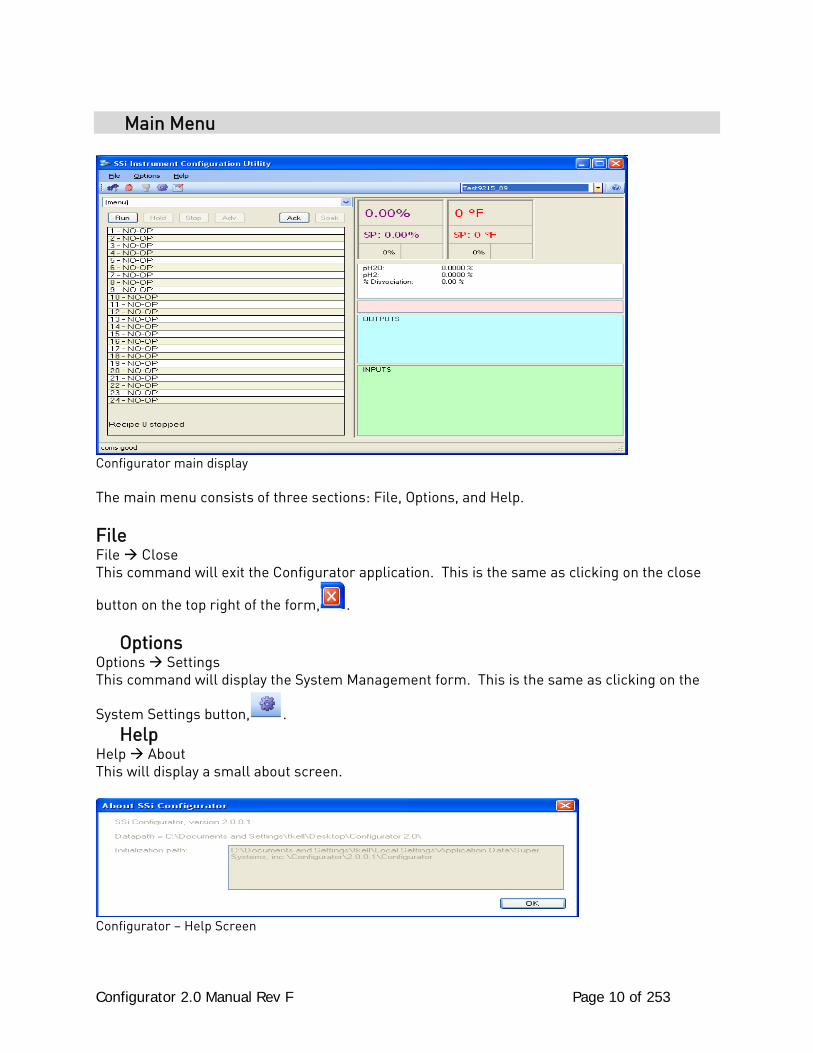
Main Menu
Configurator main display The main menu consists of three sections: File, Options, and Help. File File Close This command will exit the Configurator application. This is the same as clicking on the close
button on the top right of the form, . Options Options Settings This command will display the System Management form. This is the same as clicking on the
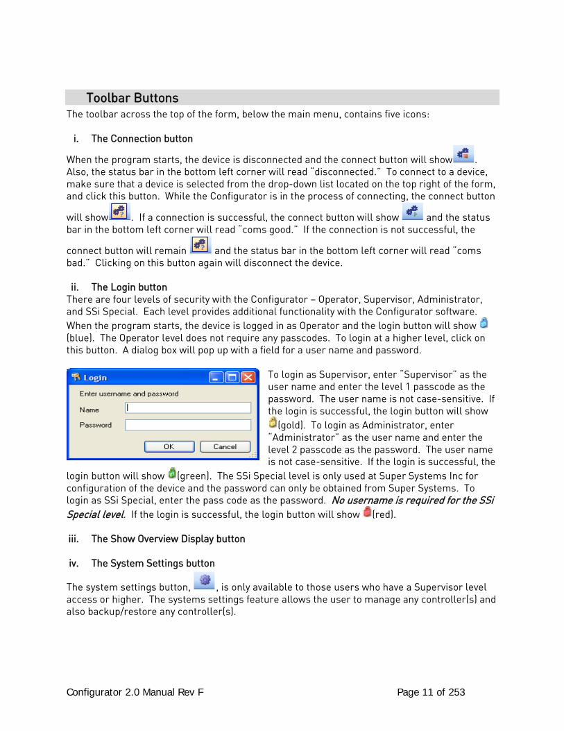
System Settings button, . Help Help About This will display a small about screen.
Configurator – Help Screen
Configurator 2.0 Manual Rev F Page 11 of 253
Toolbar Buttons The toolbar across the top of the form, below the main menu, contains five icons:
i. The Connection button
When the program starts, the device is disconnected and the connect button will show . Also, the status bar in the bottom left corner will read “disconnected.” To connect to a device, make sure that a device is selected from the drop-down list located on the top right of the form, and click this button. While the Configurator is in the process of connecting, the connect button
will show . If a connection is successful, the connect button will show and the status bar in the bottom left corner will read “coms good.” If the connection is not successful, the
connect button will remain and the status bar in the bottom left corner will read “coms bad.” Clicking on this button again will disconnect the device. ii. The Login button
There are four levels of security with the Configurator – Operator, Supervisor, Administrator, and SSi Special. Each level provides additional functionality with the Configurator software. When the program starts, the device is logged in as Operator and the login button will show (blue). The Operator level does not require any passcodes. To login at a higher level, click on this button. A dialog box will pop up with a field for a user name and password.
To login as Supervisor, enter “Supervisor” as the user name and enter the level 1 passcode as the password. The user name is not case-sensitive. If the login is successful, the login button will show
(gold). To login as Administrator, enter “Administrator” as the user name and enter the level 2 passcode as the password. The user name is not case-sensitive. If the login is successful, the
login button will show (green). The SSi Special level is only used at Super Systems Inc for configuration of the device and the password can only be obtained from Super Systems. To login as SSi Special, enter the pass code as the password. No username is required for the SSi Special level. If the login is successful, the login button will show (red). iii. The Show Overview Display button iv. The System Settings button
The system settings button, , is only available to those users who have a Supervisor level access or higher. The systems settings feature allows the user to manage any controller(s) and also backup/restore any controller(s).
Configurator 2.0 Manual Rev F Page 12 of 253
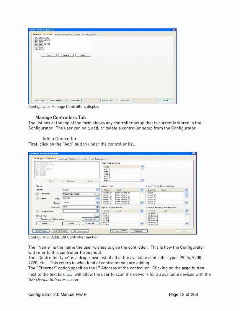
Configurator Manage Controllers display Manage Controllers Tab The list box at the top of the form shows any controller setup that is currently stored in the Configurator. The user can edit, add, or delete a controller setup from the Configurator. Add a Controller First, click on the “Add” button under the controller list.
Configurator Add/Edit Controller section
The “Name” is the name the user wishes to give the controller. This is how the Configurator will refer to this controller throughout. The “Controller Type” is a drop-down list of all of the available controller types (9005, 9200, 9220, etc). This refers to what kind of controller you are adding. The “Ethernet” option specifies the IP Address of the controller. Clicking on the scan button next to the text box, , will allow the user to scan the network for all available devices with the SSi Device Selector screen.
Configurator 2.0 Manual Rev F Page 13 of 253
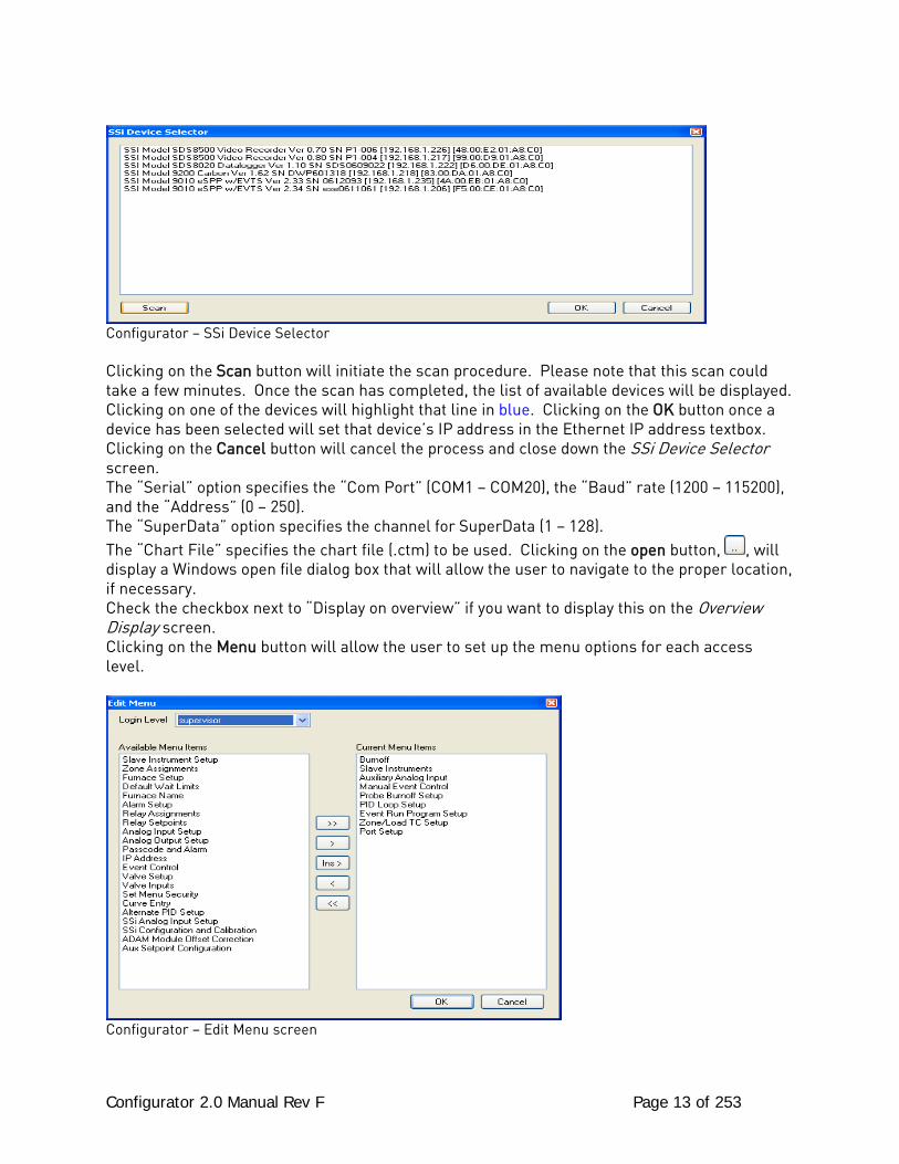
Configurator – SSi Device Selector Clicking on the Scan button will initiate the scan procedure. Please note that this scan could take a few minutes. Once the scan has completed, the list of available devices will be displayed. Clicking on one of the devices will highlight that line in blue. Clicking on the OK button once a device has been selected will set that device’s IP address in the Ethernet IP address textbox. Clicking on the Cancel button will cancel the process and close down the SSi Device Selector screen. The “Serial” option specifies the “Com Port” (COM1 – COM20), the “Baud” rate (1200 – 115200), and the “Address” (0 – 250). The “SuperData” option specifies the channel for SuperData (1 – 128). The “Chart File” specifies the chart file (.ctm) to be used. Clicking on the open button, , will display a Windows open file dialog box that will allow the user to navigate to the proper location, if necessary. Check the checkbox next to “Display on overview” if you want to display this on the Overview Display screen. Clicking on the Menu button will allow the user to set up the menu options for each access level.
Configurator – Edit Menu screen
Configurator 2.0 Manual Rev F Page 14 of 253
Use the drop-down list at the top of the form to select the access level to change. The list on the right of the screen is the current menu list for the specific access level. The list on the left of the screen lists the remaining items. To add a menu option, select the desired menu option
on the left and click on the Add button, . To add all of the menu options at once, click on
the Add All button, . To remove a menu option, select the desired menu option on the
right and click on the Remove button, . To remove all of the menu options at once, click
on the Remove All button, . To add a menu option to a specific position, click on the menu option on the right where the new option will be inserted, click on the menu option on the left to
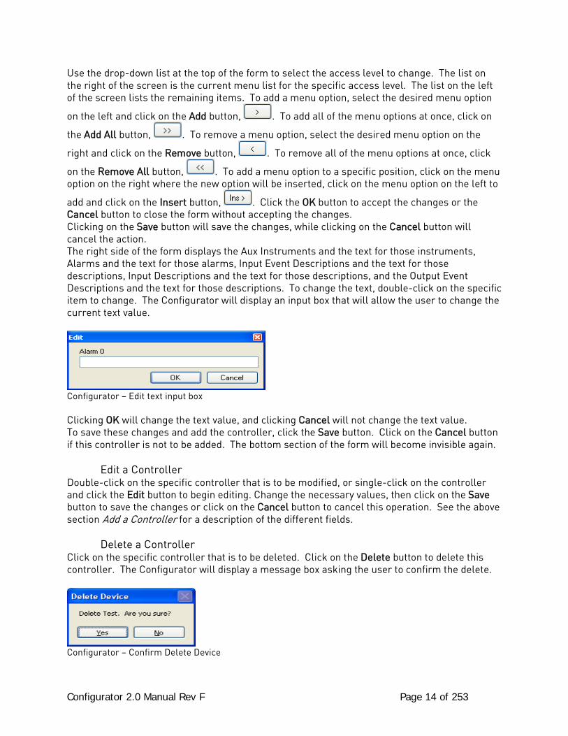
add and click on the Insert button, . Click the OK button to accept the changes or the Cancel button to close the form without accepting the changes. Clicking on the Save button will save the changes, while clicking on the Cancel button will cancel the action. The right side of the form displays the Aux Instruments and the text for those instruments, Alarms and the text for those alarms, Input Event Descriptions and the text for those descriptions, Input Descriptions and the text for those descriptions, and the Output Event Descriptions and the text for those descriptions. To change the text, double-click on the specific item to change. The Configurator will display an input box that will allow the user to change the current text value.
Configurator – Edit text input box Clicking OK will change the text value, and clicking Cancel will not change the text value. To save these changes and add the controller, click the Save button. Click on the Cancel button if this controller is not to be added. The bottom section of the form will become invisible again. Edit a Controller Double-click on the specific controller that is to be modified, or single-click on the controller and click the Edit button to begin editing. Change the necessary values, then click on the Save button to save the changes or click on the Cancel button to cancel this operation. See the above section Add a Controller for a description of the different fields. Delete a Controller Click on the specific controller that is to be deleted. Click on the Delete button to delete this controller. The Configurator will display a message box asking the user to confirm the delete.
Configurator – Confirm Delete Device
Configurator 2.0 Manual Rev F Page 15 of 253
Clicking on the Yes button will delete the controller. Clicking on the No button will cancel the delete. Backup/Restore Tab
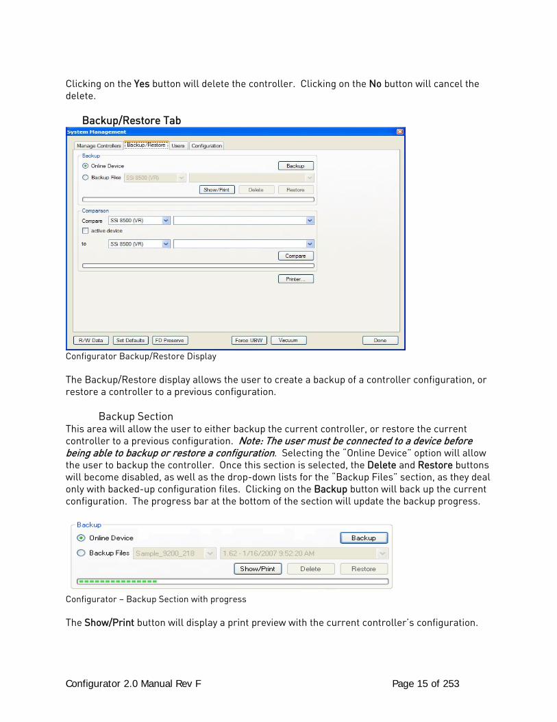
Configurator Backup/Restore Display
The Backup/Restore display allows the user to create a backup of a controller configuration, or restore a controller to a previous configuration. Backup Section This area will allow the user to either backup the current controller, or restore the current controller to a previous configuration. Note: The user must be connected to a device before being able to backup or restore a configuration. Selecting the “Online Device” option will allow the user to backup the controller. Once this section is selected, the Delete and Restore buttons will become disabled, as well as the drop-down lists for the “Backup Files” section, as they deal only with backed-up configuration files. Clicking on the Backup button will back up the current configuration. The progress bar at the bottom of the section will update the backup progress.
Configurator – Backup Section with progress The Show/Print button will display a print preview with the current controller’s configuration.
Configurator 2.0 Manual Rev F Page 16 of 253
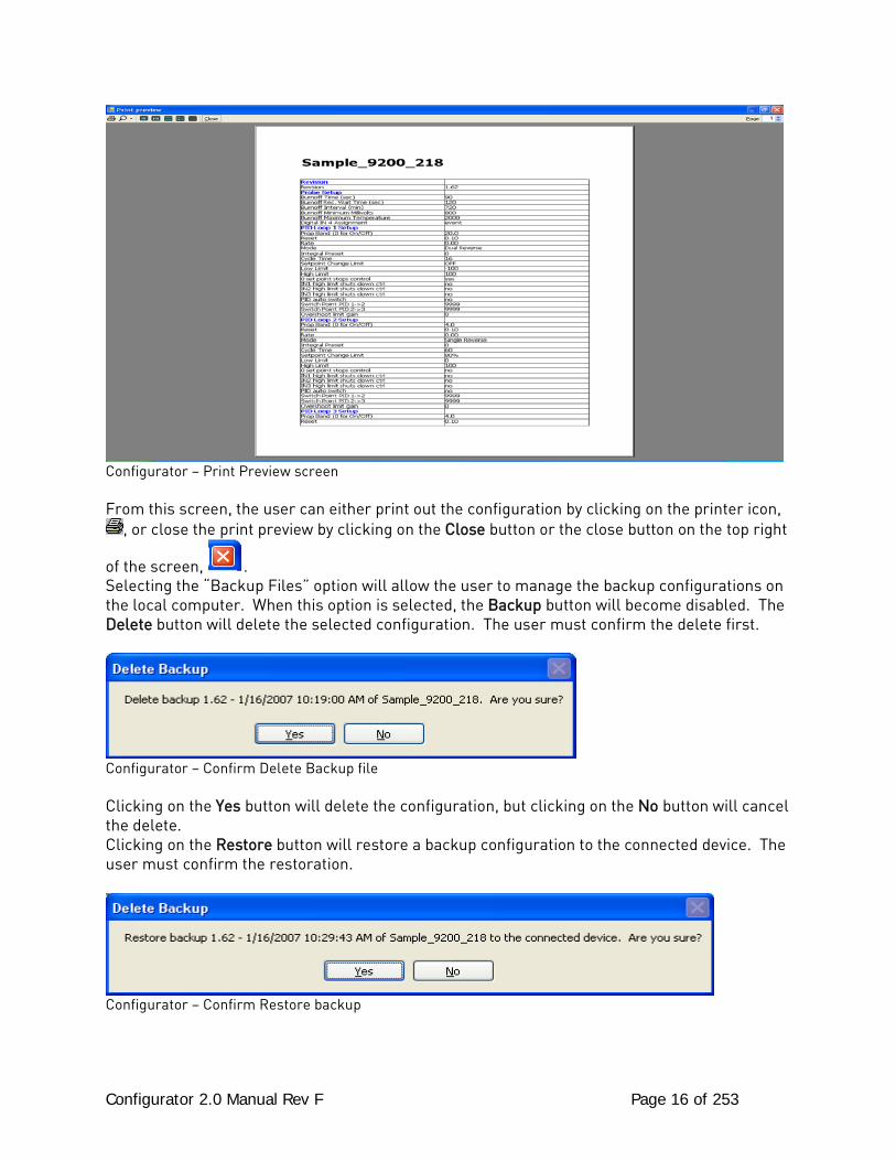
Configurator – Print Preview screen
From this screen, the user can either print out the configuration by clicking on the printer icon,
, or close the print preview by clicking on the Close button or the close button on the top right
of the screen, . Selecting the “Backup Files” option will allow the user to manage the backup configurations on the local computer. When this option is selected, the Backup button will become disabled. The Delete button will delete the selected configuration. The user must confirm the delete first.
Configurator – Confirm Delete Backup file Clicking on the Yes button will delete the configuration, but clicking on the No button will cancel the delete. Clicking on the Restore button will restore a backup configuration to the connected device. The user must confirm the restoration.
Configurator – Confirm Restore backup
Configurator 2.0 Manual Rev F Page 17 of 253
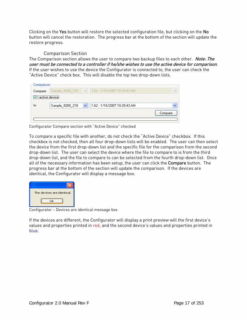
Clicking on the Yes button will restore the selected configuration file, but clicking on the No button will cancel the restoration. The progress bar at the bottom of the section will update the restore progress. Comparison Section The Comparison section allows the user to compare two backup files to each other. Note: The user must be connected to a controller if he/she wishes to use the active device for comparison. If the user wishes to use the device the Configurator is connected to, the user can check the “Active Device” check box. This will disable the top two drop-down lists.
Configurator Compare section with “Active Device” checked
To compare a specific file with another, do not check the “Active Device” checkbox. If this checkbox is not checked, then all four drop-down lists will be enabled. The user can then select the device from the first drop-down list and the specific file for the comparison from the second drop-down list. The user can select the device where the file to compare to is from the third drop-down list, and the file to compare to can be selected from the fourth drop-down list. Once all of the necessary information has been setup, the user can click the Compare button. The progress bar at the bottom of the section will update the comparison. If the devices are identical, the Configurator will display a message box.
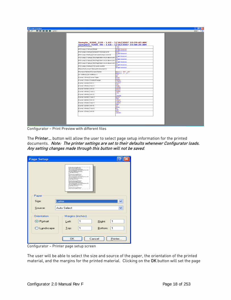
Configurator – Devices are identical message box If the devices are different, the Configurator will display a print preview will the first device’s values and properties printed in red, and the second device’s values and properties printed in blue.
Configurator 2.0 Manual Rev F Page 18 of 253
Configurator – Print Preview with different files The Printer… button will allow the user to select page setup information for the printed documents. Note: The printer settings are set to their defaults whenever Configurator loads. Any setting changes made through this button will not be saved.
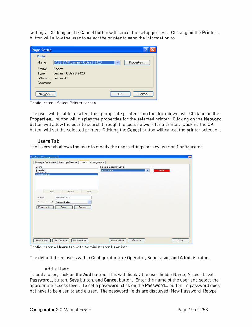
Configurator – Printer page setup screen The user will be able to select the size and source of the paper, the orientation of the printed material, and the margins for the printed material. Clicking on the OK button will set the page
Configurator 2.0 Manual Rev F Page 19 of 253
settings. Clicking on the Cancel button will cancel the setup process. Clicking on the Printer… button will allow the user to select the printer to send the information to.
Configurator – Select Printer screen The user will be able to select the appropriate printer from the drop-down list. Clicking on the Properties… button will display the properties for the selected printer. Clicking on the Network button will allow the user to search through the local network for a printer. Clicking the OK button will set the selected printer. Clicking the Cancel button will cancel the printer selection. Users Tab The Users tab allows the user to modify the user settings for any user on Configurator.
Configurator – Users tab with Administrator User info The default three users within Configurator are: Operator, Supervisor, and Administrator. Add a User To add a user, click on the Add button. This will display the user fields: Name, Access Level, Password… button, Save button, and Cancel button. Enter the name of the user and select the appropriate access level. To set a password, click on the Password… button. A password does not have to be given to add a user. The password fields are displayed: New Password, Retype
Configurator 2.0 Manual Rev F Page 20 of 253
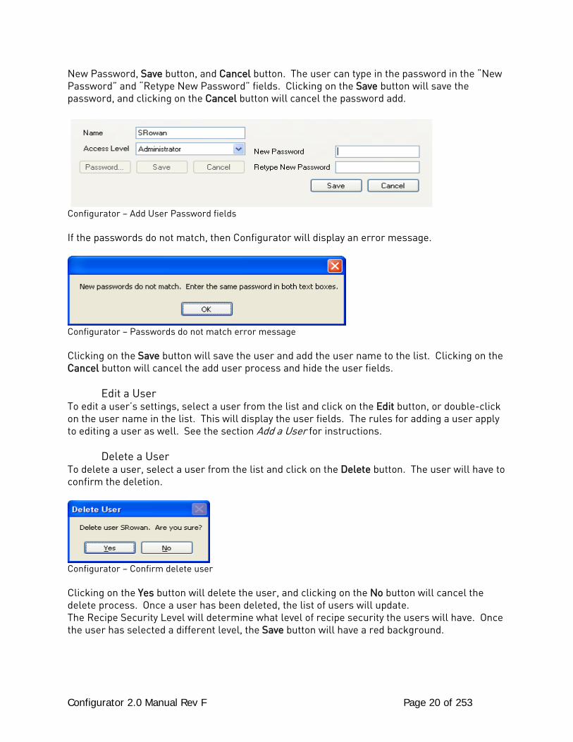
New Password, Save button, and Cancel button. The user can type in the password in the “New Password” and “Retype New Password” fields. Clicking on the Save button will save the password, and clicking on the Cancel button will cancel the password add.
Configurator – Add User Password fields If the passwords do not match, then Configurator will display an error message.
Configurator – Passwords do not match error message Clicking on the Save button will save the user and add the user name to the list. Clicking on the Cancel button will cancel the add user process and hide the user fields. Edit a User To edit a user’s settings, select a user from the list and click on the Edit button, or double-click on the user name in the list. This will display the user fields. The rules for adding a user apply to editing a user as well. See the section Add a User for instructions. Delete a User To delete a user, select a user from the list and click on the Delete button. The user will have to confirm the deletion.
Configurator – Confirm delete user Clicking on the Yes button will delete the user, and clicking on the No button will cancel the delete process. Once a user has been deleted, the list of users will update. The Recipe Security Level will determine what level of recipe security the users will have. Once the user has selected a different level, the Save button will have a red background.
Configurator 2.0 Manual Rev F Page 21 of 253
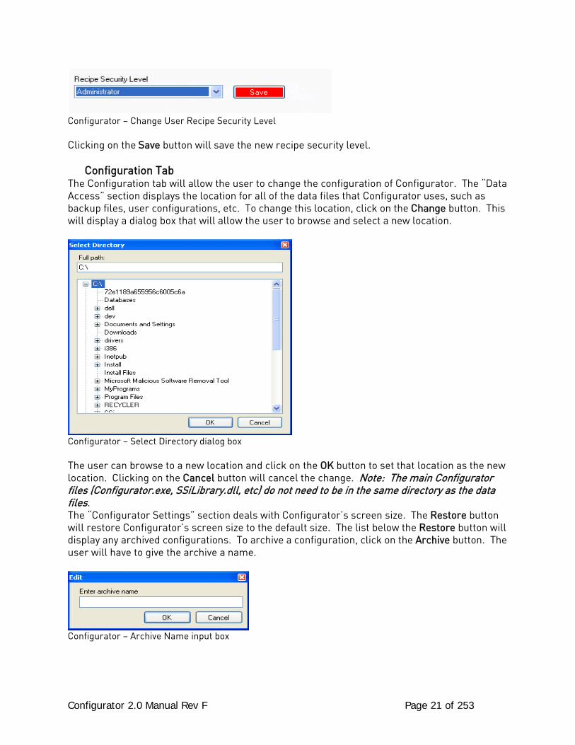
Configurator – Change User Recipe Security Level Clicking on the Save button will save the new recipe security level. Configuration Tab The Configuration tab will allow the user to change the configuration of Configurator. The “Data Access” section displays the location for all of the data files that Configurator uses, such as backup files, user configurations, etc. To change this location, click on the Change button. This will display a dialog box that will allow the user to browse and select a new location.
Configurator – Select Directory dialog box The user can browse to a new location and click on the OK button to set that location as the new location. Clicking on the Cancel button will cancel the change. Note: The main Configurator files (Configurator.exe, SSiLibrary.dll, etc) do not need to be in the same directory as the data files. The “Configurator Settings” section deals with Configurator’s screen size. The Restore button will restore Configurator’s screen size to the default size. The list below the Restore button will display any archived configurations. To archive a configuration, click on the Archive button. The user will have to give the archive a name.
Configurator – Archive Name input box
Configurator 2.0 Manual Rev F Page 22 of 253
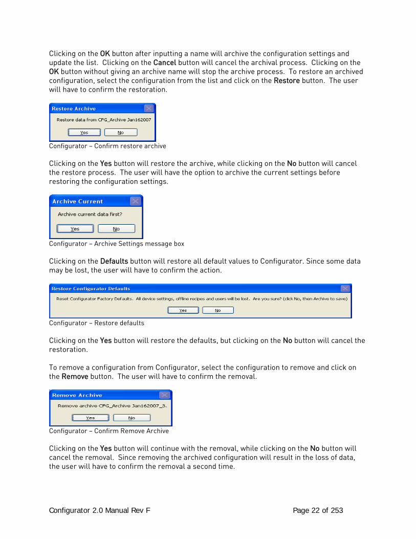
Clicking on the OK button after inputting a name will archive the configuration settings and update the list. Clicking on the Cancel button will cancel the archival process. Clicking on the OK button without giving an archive name will stop the archive process. To restore an archived configuration, select the configuration from the list and click on the Restore button. The user will have to confirm the restoration.
Configurator – Confirm restore archive Clicking on the Yes button will restore the archive, while clicking on the No button will cancel the restore process. The user will have the option to archive the current settings before restoring the configuration settings.
Configurator – Archive Settings message box Clicking on the Defaults button will restore all default values to Configurator. Since some data may be lost, the user will have to confirm the action.
Configurator – Restore defaults Clicking on the Yes button will restore the defaults, but clicking on the No button will cancel the restoration. To remove a configuration from Configurator, select the configuration to remove and click on the Remove button. The user will have to confirm the removal.
Configurator – Confirm Remove Archive Clicking on the Yes button will continue with the removal, while clicking on the No button will cancel the removal. Since removing the archived configuration will result in the loss of data, the user will have to confirm the removal a second time.
Configurator 2.0 Manual Rev F Page 23 of 253
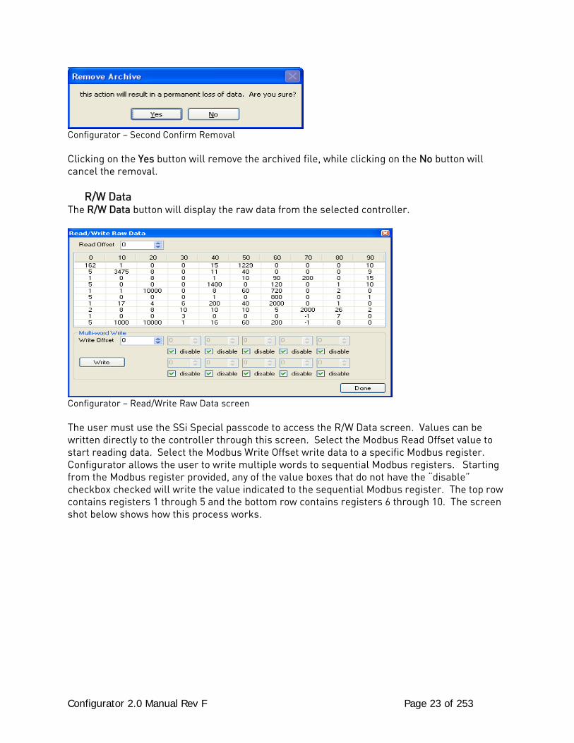
Configurator – Second Confirm Removal Clicking on the Yes button will remove the archived file, while clicking on the No button will cancel the removal. R/W Data The R/W Data button will display the raw data from the selected controller.
Configurator – Read/Write Raw Data screen The user must use the SSi Special passcode to access the R/W Data screen. Values can be written directly to the controller through this screen. Select the Modbus Read Offset value to start reading data. Select the Modbus Write Offset write data to a specific Modbus register. Configurator allows the user to write multiple words to sequential Modbus registers. Starting from the Modbus register provided, any of the value boxes that do not have the “disable” checkbox checked will write the value indicated to the sequential Modbus register. The top row contains registers 1 through 5 and the bottom row contains registers 6 through 10. The screen shot below shows how this process works.
Configurator 2.0 Manual Rev F Page 24 of 253
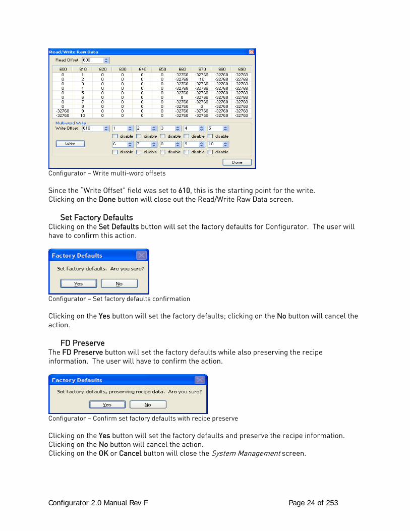
Configurator – Write multi-word offsets Since the “Write Offset” field was set to 610, this is the starting point for the write. Clicking on the Done button will close out the Read/Write Raw Data screen. Set Factory Defaults Clicking on the Set Defaults button will set the factory defaults for Configurator. The user will have to confirm this action.
Configurator – Set factory defaults confirmation Clicking on the Yes button will set the factory defaults; clicking on the No button will cancel the action. FD Preserve The FD Preserve button will set the factory defaults while also preserving the recipe information. The user will have to confirm the action.
Configurator – Confirm set factory defaults with recipe preserve Clicking on the Yes button will set the factory defaults and preserve the recipe information. Clicking on the No button will cancel the action. Clicking on the OK or Cancel button will close the System Management screen.
Configurator 2.0 Manual Rev F Page 25 of 253
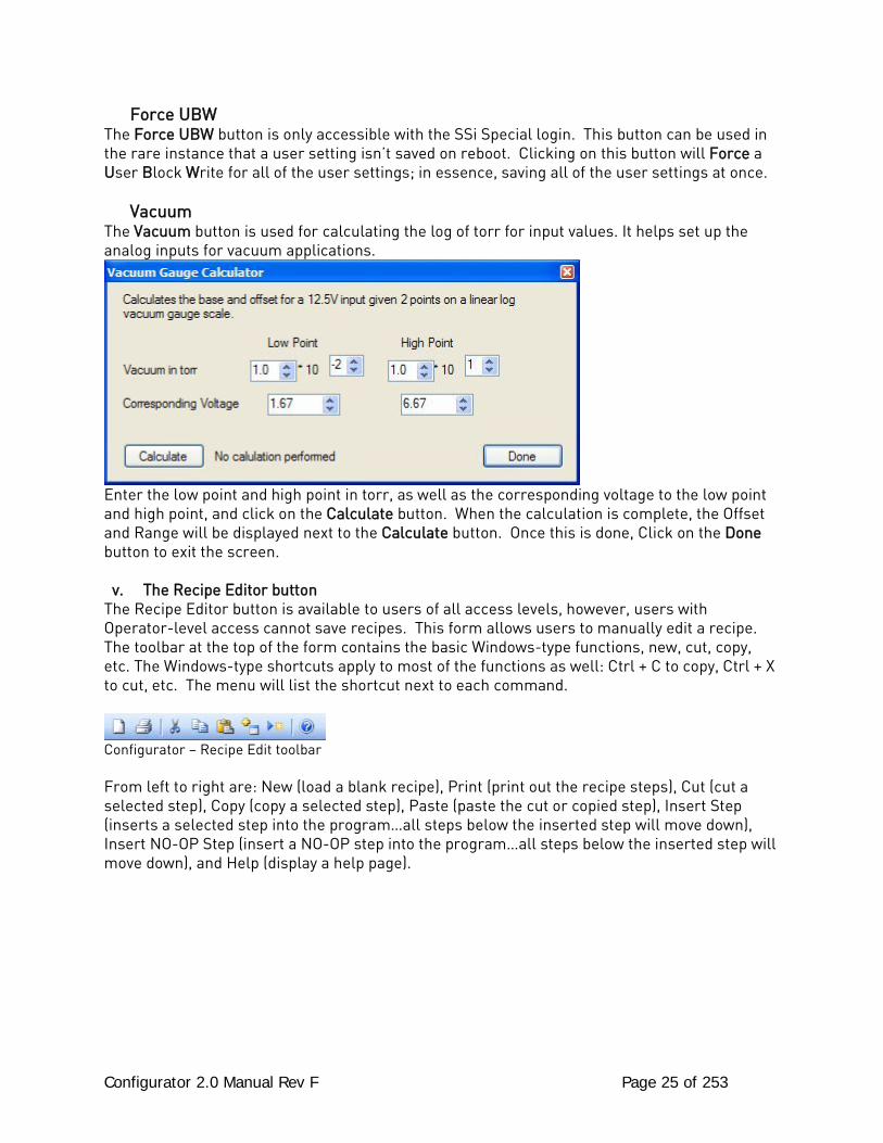
Force UBW The Force UBW button is only accessible with the SSi Special login. This button can be used in the rare instance that a user setting isn’t saved on reboot. Clicking on this button will Force a User Block Write for all of the user settings; in essence, saving all of the user settings at once. Vacuum The Vacuum button is used for calculating the log of torr for input values. It helps set up the analog inputs for vacuum applications.
Enter the low point and high point in torr, as well as the corresponding voltage to the low point and high point, and click on the Calculate button. When the calculation is complete, the Offset and Range will be displayed next to the Calculate button. Once this is done, Click on the Done button to exit the screen.
v. The Recipe Editor button The Recipe Editor button is available to users of all access levels, however, users with Operator-level access cannot save recipes. This form allows users to manually edit a recipe. The toolbar at the top of the form contains the basic Windows-type functions, new, cut, copy, etc. The Windows-type shortcuts apply to most of the functions as well: Ctrl + C to copy, Ctrl + X to cut, etc. The menu will list the shortcut next to each command.
Configurator – Recipe Edit toolbar From left to right are: New (load a blank recipe), Print (print out the recipe steps), Cut (cut a selected step), Copy (copy a selected step), Paste (paste the cut or copied step), Insert Step (inserts a selected step into the program…all steps below the inserted step will move down), Insert NO-OP Step (insert a NO-OP step into the program…all steps below the inserted step will move down), and Help (display a help page).
Configurator 2.0 Manual Rev F Page 26 of 253
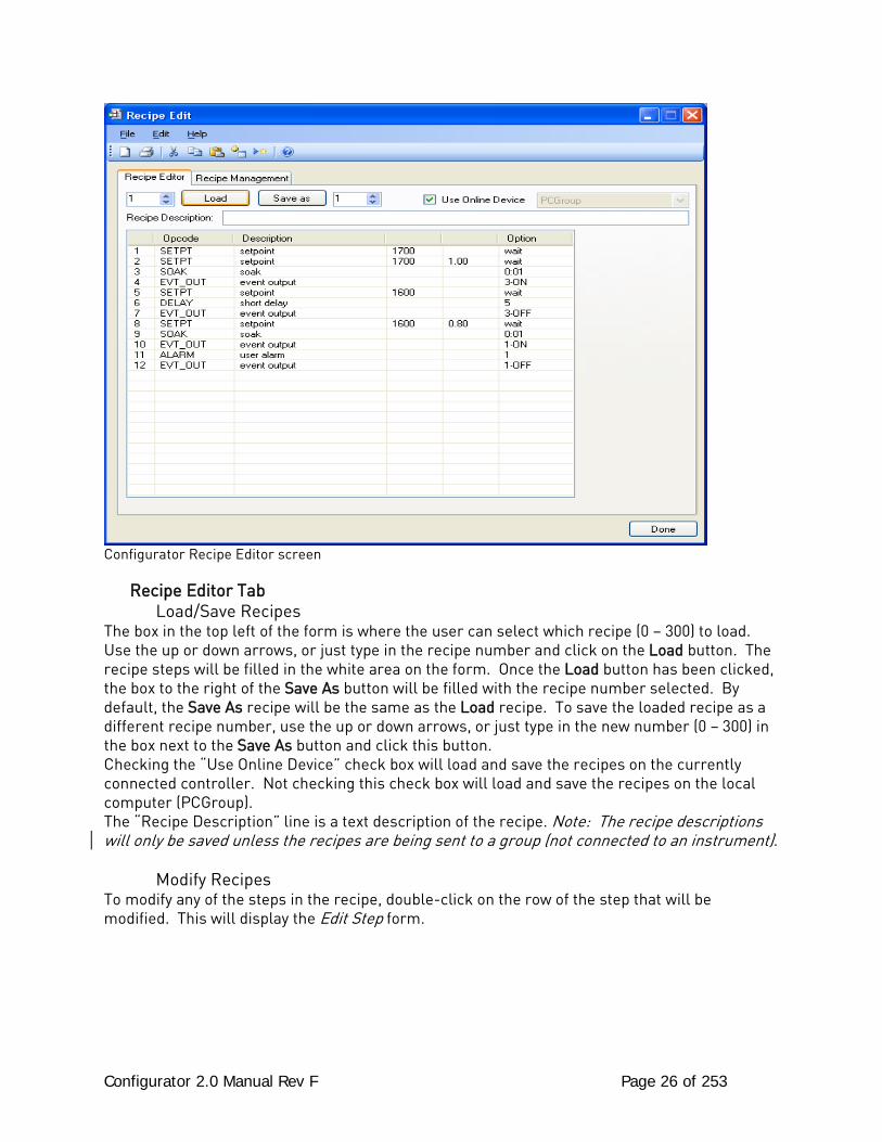
Configurator Recipe Editor screen
Recipe Editor Tab Load/Save Recipes The box in the top left of the form is where the user can select which recipe (0 – 300) to load. Use the up or down arrows, or just type in the recipe number and click on the Load button. The recipe steps will be filled in the white area on the form. Once the Load button has been clicked, the box to the right of the Save As button will be filled with the recipe number selected. By default, the Save As recipe will be the same as the Load recipe. To save the loaded recipe as a different recipe number, use the up or down arrows, or just type in the new number (0 – 300) in the box next to the Save As button and click this button. Checking the “Use Online Device” check box will load and save the recipes on the currently connected controller. Not checking this check box will load and save the recipes on the local computer (PCGroup). The “Recipe Description” line is a text description of the recipe. Note: The recipe descriptions will only be saved unless the recipes are being sent to a group (not connected to an instrument). Modify Recipes To modify any of the steps in the recipe, double-click on the row of the step that will be modified. This will display the Edit Step form.
Configurator 2.0 Manual Rev F Page 27 of 253
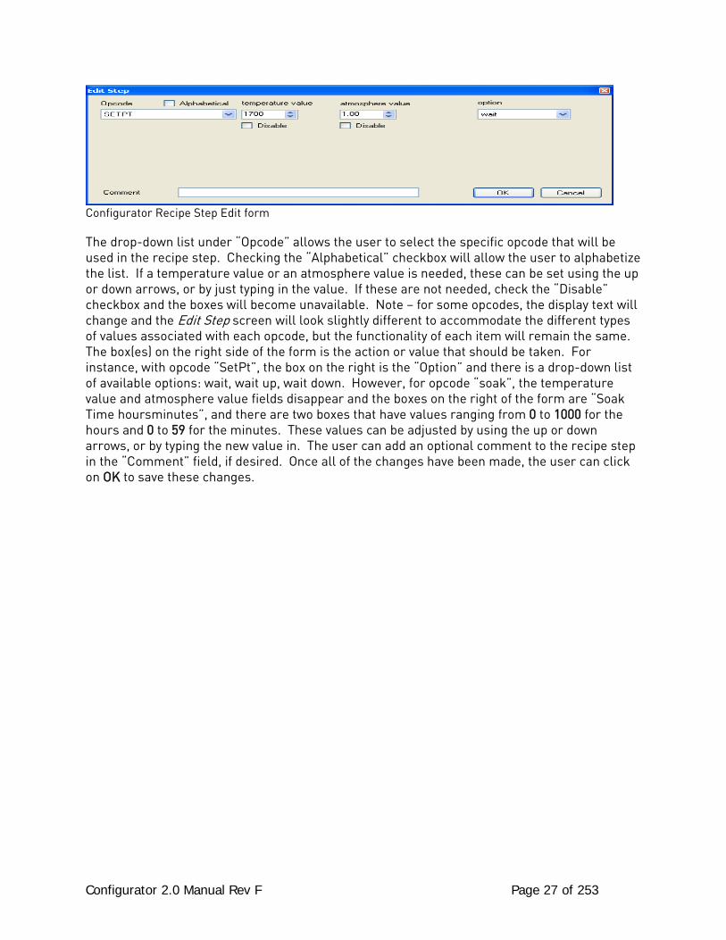
Configurator Recipe Step Edit form
The drop-down list under “Opcode” allows the user to select the specific opcode that will be used in the recipe step. Checking the “Alphabetical” checkbox will allow the user to alphabetize the list. If a temperature value or an atmosphere value is needed, these can be set using the up or down arrows, or by just typing in the value. If these are not needed, check the “Disable” checkbox and the boxes will become unavailable. Note – for some opcodes, the display text will change and the Edit Step screen will look slightly different to accommodate the different types of values associated with each opcode, but the functionality of each item will remain the same. The box(es) on the right side of the form is the action or value that should be taken. For instance, with opcode “SetPt”, the box on the right is the “Option” and there is a drop-down list of available options: wait, wait up, wait down. However, for opcode “soak”, the temperature value and atmosphere value fields disappear and the boxes on the right of the form are “Soak Time hoursminutes”, and there are two boxes that have values ranging from 0 to 1000 for the hours and 0 to 59 for the minutes. These values can be adjusted by using the up or down arrows, or by typing the new value in. The user can add an optional comment to the recipe step in the “Comment” field, if desired. Once all of the changes have been made, the user can click on OK to save these changes.
Configurator 2.0 Manual Rev F Page 28 of 253
Recipe Management Tab
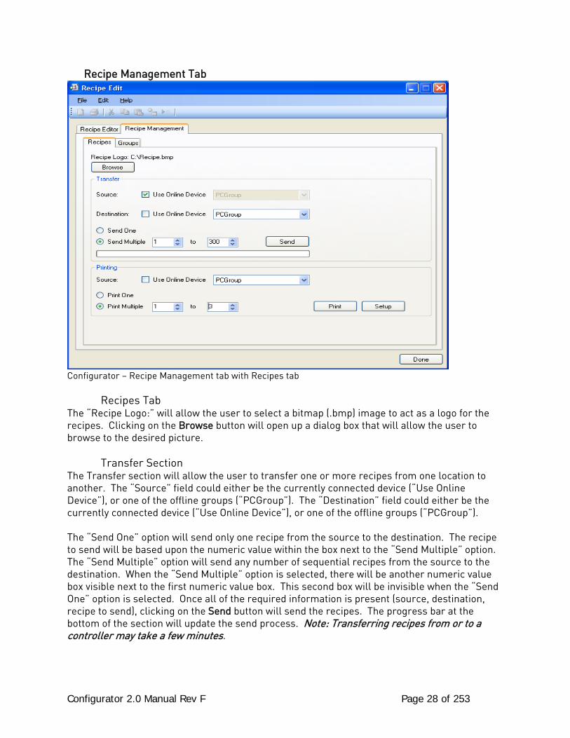
Configurator – Recipe Management tab with Recipes tab Recipes Tab The “Recipe Logo:” will allow the user to select a bitmap (.bmp) image to act as a logo for the recipes. Clicking on the Browse button will open up a dialog box that will allow the user to browse to the desired picture. Transfer Section The Transfer section will allow the user to transfer one or more recipes from one location to another. The “Source” field could either be the currently connected device (“Use Online Device”), or one of the offline groups (“PCGroup”). The “Destination” field could either be the currently connected device (“Use Online Device”), or one of the offline groups (“PCGroup”). The “Send One” option will send only one recipe from the source to the destination. The recipe to send will be based upon the numeric value within the box next to the “Send Multiple” option. The “Send Multiple” option will send any number of sequential recipes from the source to the destination. When the “Send Multiple” option is selected, there will be another numeric value box visible next to the first numeric value box. This second box will be invisible when the “Send One” option is selected. Once all of the required information is present (source, destination, recipe to send), clicking on the Send button will send the recipes. The progress bar at the bottom of the section will update the send process. Note: Transferring recipes from or to a controller may take a few minutes.
Configurator 2.0 Manual Rev F Page 29 of 253
Printing Section The Printing section allows the user the ability to print out recipes. The “Source” field could either be the currently connected device (“Use Online Device”), or one of the offline groups (“PCGroup”). The “Print One” option will print only one recipe from the source. The recipe to print will be based upon the numeric value within the box next to the “Print Multiple” option. The “Print Multiple” option will print any number of sequential recipes from the source. When the “Print Multiple” option is selected, there will be another numeric value box visible next to the first numeric value box. This second box will be invisible when the “Print One” option is selected. Clicking on the Print button will display a print preview dialog, where the user will be able to view and/or print the recipes. Clicking on the Setup button will display a Page Setup screen, which will allow the user to set up the page settings for printing, as well as select the printer. Note: Printing recipes from a controller may take a few minutes. Groups Tab
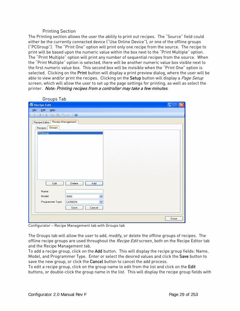
Configurator – Recipe Management tab with Groups tab The Groups tab will allow the user to add, modify, or delete the offline groups of recipes. The offline recipe groups are used throughout the Recipe Edit screen, both on the Recipe Editor tab and the Recipe Management tab. To add a recipe group, click on the Add button. This will display the recipe group fields: Name, Model, and Programmer Type. Enter or select the desired values and click the Save button to save the new group, or click the Cancel button to cancel the add process. To edit a recipe group, click on the group name to edit from the list and click on the Edit buttons, or double-click the group name in the list. This will display the recipe group fields with
Configurator 2.0 Manual Rev F Page 30 of 253
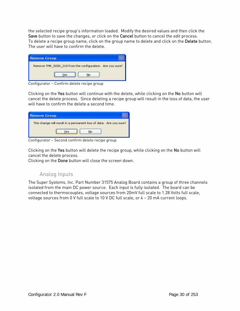
the selected recipe group’s information loaded. Modify the desired values and then click the Save button to save the changes, or click on the Cancel button to cancel the edit process. To delete a recipe group name, click on the group name to delete and click on the Delete button. The user will have to confirm the delete.
Configurator – Confirm delete recipe group Clicking on the Yes button will continue with the delete, while clicking on the No button will cancel the delete process. Since deleting a recipe group will result in the loss of data, the user will have to confirm the delete a second time.
Configurator – Second confirm delete recipe group Clicking on the Yes button will delete the recipe group, while clicking on the No button will cancel the delete process. Clicking on the Done button will close the screen down.
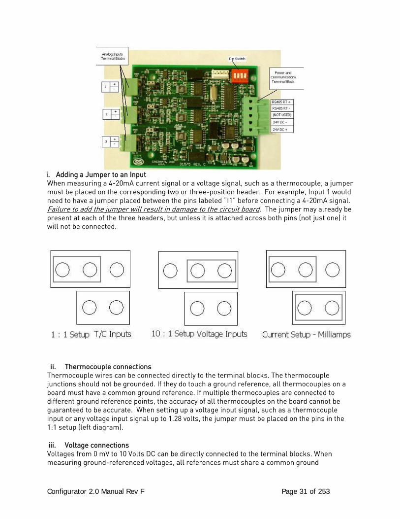
Analog Inputs The Super Systems, Inc. Part Number 31575 Analog Board contains a group of three channels isolated from the main DC power source. Each input is fully isolated. The board can be connected to thermocouples, voltage sources from 20mV full scale to 1.28 Volts full scale, voltage sources from 0 V full scale to 10 V DC full scale, or 4 – 20 mA current loops.
Configurator 2.0 Manual Rev F Page 31 of 253
i. Adding a Jumper to an Input When measuring a 4-20mA current signal or a voltage signal, such as a thermocouple, a jumper must be placed on the corresponding two or three-position header. For example, Input 1 would need to have a jumper placed between the pins labeled “I1” before connecting a 4-20mA signal. Failure to add the jumper will result in damage to the circuit board. The jumper may already be present at each of the three headers, but unless it is attached across both pins (not just one) it will not be connected.
ii. Thermocouple connections Thermocouple wires can be connected directly to the terminal blocks. The thermocouple junctions should not be grounded. If they do touch a ground reference, all thermocouples on a board must have a common ground reference. If multiple thermocouples are connected to different ground reference points, the accuracy of all thermocouples on the board cannot be guaranteed to be accurate. When setting up a voltage input signal, such as a thermocouple input or any voltage input signal up to 1.28 volts, the jumper must be placed on the pins in the 1:1 setup (left diagram).
iii. Voltage connections Voltages from 0 mV to 10 Volts DC can be directly connected to the terminal blocks. When measuring ground-referenced voltages, all references must share a common ground

Configurator 2.0 Manual Rev F Page 32 of 253
reference. If the voltage sources are connected to different ground reference points, the accuracy of all the voltage sources connected to the board need to be checked for accuracy. Since higher voltages can damage the input board, any voltage input signals, such as a vacuum gauge, must have the jumpers placed on the pins in the 10:1 setup (middle diagram). This will insure that any signal going into the board will be scaled down so it will not damage the input board.
iv. 4 – 20 mA. Current Loop connections Before connecting the current loop, insert the shorting jumper on the board for each channel used to measure current loops. This jumper inserts the 62-ohm shunt resistor across the input of the A/D. If multiple current loops are connected to one board, all must share the same power supply and ground reference points or the accuracy of all the current loops need to be checked for accuracy. When setting up a current input signal, such as a 4 – 20 mA signal, the jumper must be placed on the pins in the current setup (right diagram). Notice that there is also a jumper set up in the 1:1 setup only when inputting a current signal. This is because current signals also have a corresponding voltage signal.
Warning: Connecting a mA input without the Input Jumper will damage the input.
1. To add a jumper to an input: 2. Power down the unit. 3. Remove any cables from the unit. 4. Pull the top of the unit apart from the base 5. Grasping both sides of the input board, carefully pull the input board out of the video recorder and set the jumper for the appropriate set of pins, i.e. “V1” for input 1, “V2” for input 2, etc. A jumper will need to be set – placed on both pins – to be considered “on”. Slide the input board back into the video recorder slot. 6. Reconnect the top of the unit to the base. 7. Re-connect the Ethernet cable and thermocouple connector.
Setting the DIP switches to Assign Board Numbers Each input board must have a unique address assigned by the DIP switches on each input board. A unique address will ensure that the instrument will correctly read all of the boards set up. If two or more boards have the same address, multiple errors could occur such as: reading data from one board one second, then reading data from another board the next second, no data being
read, etc. It is important that each board has a unique address. Each DIP switch has four switches on it labeled: 1, 2, 3, and 4. These numbers follow a binary numbering system – i.e. 1 = 1, 2 = 2, 3 = 4, and 4 = 8. There is an ON and an OFF position for each switch. OFF = 0 and ON =

Configurator 2.0 Manual Rev F Page 33 of 253
1. Each board number can be assigned by setting the appropriate switches to ON. For example, to set a board number to 1, set the “1” switch to ON and the “2”, “3”, and “4” switches to OFF ((1*1) + (2*0) + (4*0) + (8*0) = 1). To set the board number to 10, set the “1” and “3” switches to OFF and the “2” and “4” switches to ON ((1*0) + (2*1) + (4*0) + (8*1) = 10). The exception to the rule is setting a board number to 16 – all switches are off.
Configurator 2.0 Manual Rev F Page 34 of 253
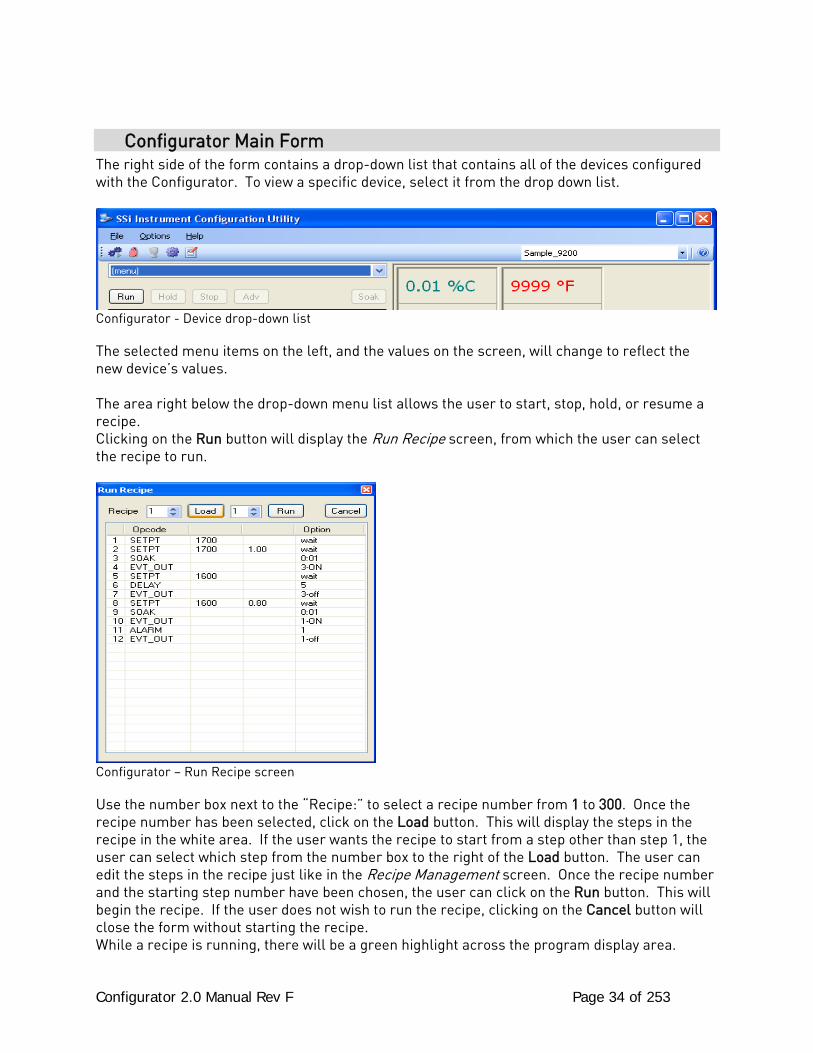
Configurator Main Form The right side of the form contains a drop-down list that contains all of the devices configured with the Configurator. To view a specific device, select it from the drop down list.
Configurator - Device drop-down list The selected menu items on the left, and the values on the screen, will change to reflect the new device’s values. The area right below the drop-down menu list allows the user to start, stop, hold, or resume a recipe. Clicking on the Run button will display the Run Recipe screen, from which the user can select the recipe to run.
Configurator – Run Recipe screen Use the number box next to the “Recipe:” to select a recipe number from 1 to 300. Once the recipe number has been selected, click on the Load button. This will display the steps in the recipe in the white area. If the user wants the recipe to start from a step other than step 1, the user can select which step from the number box to the right of the Load button. The user can edit the steps in the recipe just like in the Recipe Management screen. Once the recipe number and the starting step number have been chosen, the user can click on the Run button. This will begin the recipe. If the user does not wish to run the recipe, clicking on the Cancel button will close the form without starting the recipe. While a recipe is running, there will be a green highlight across the program display area.
Configurator 2.0 Manual Rev F Page 35 of 253
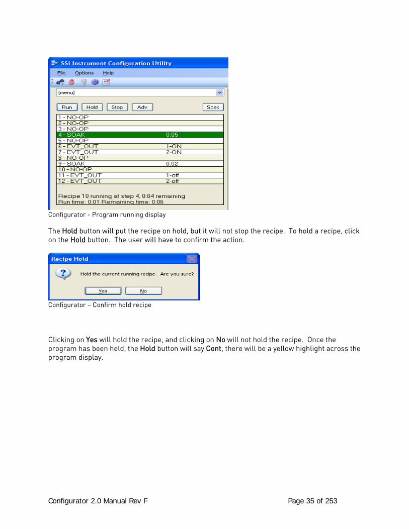
Configurator - Program running display The Hold button will put the recipe on hold, but it will not stop the recipe. To hold a recipe, click on the Hold button. The user will have to confirm the action.
Configurator – Confirm hold recipe Clicking on Yes will hold the recipe, and clicking on No will not hold the recipe. Once the program has been held, the Hold button will say Cont, there will be a yellow highlight across the program display.
Configurator 2.0 Manual Rev F Page 36 of 253
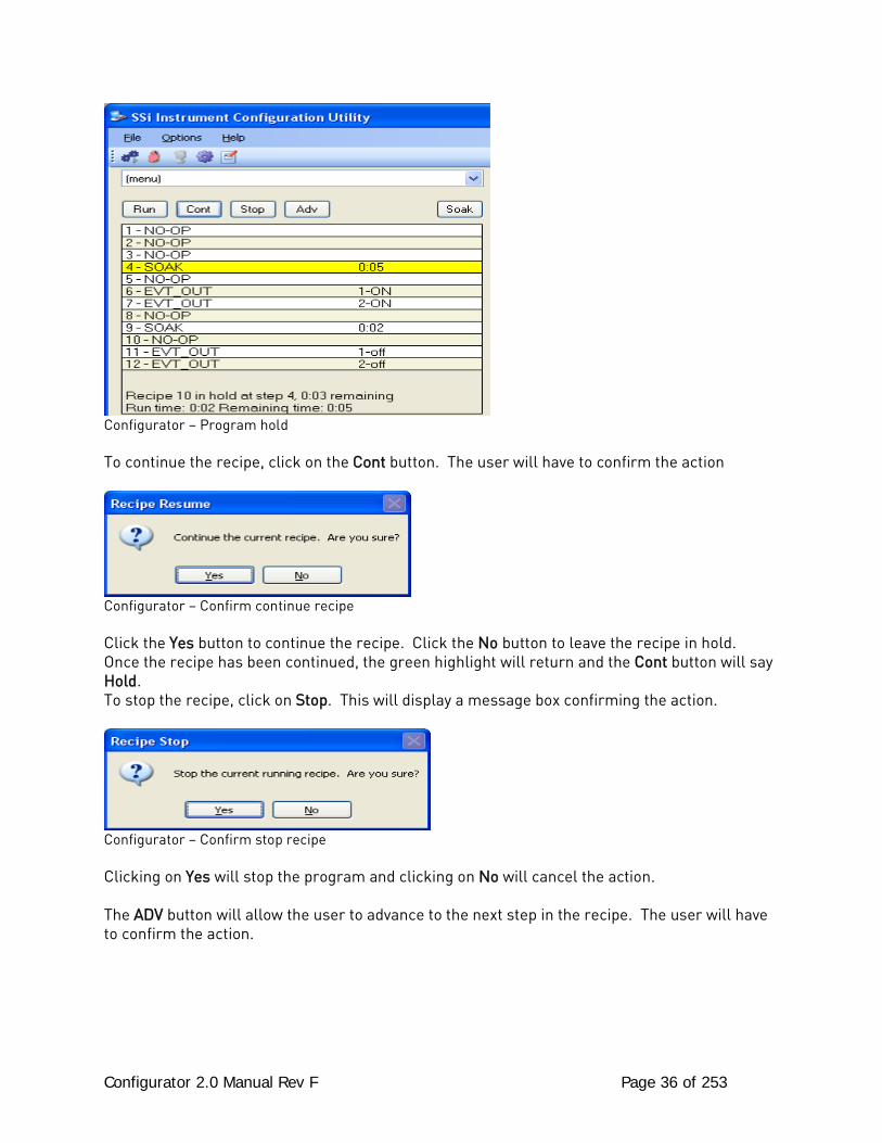
Configurator – Program hold To continue the recipe, click on the Cont button. The user will have to confirm the action
Configurator – Confirm continue recipe Click the Yes button to continue the recipe. Click the No button to leave the recipe in hold. Once the recipe has been continued, the green highlight will return and the Cont button will say Hold. To stop the recipe, click on Stop. This will display a message box confirming the action.
Configurator – Confirm stop recipe Clicking on Yes will stop the program and clicking on No will cancel the action. The ADV button will allow the user to advance to the next step in the recipe. The user will have to confirm the action.
Configurator 2.0 Manual Rev F Page 37 of 253
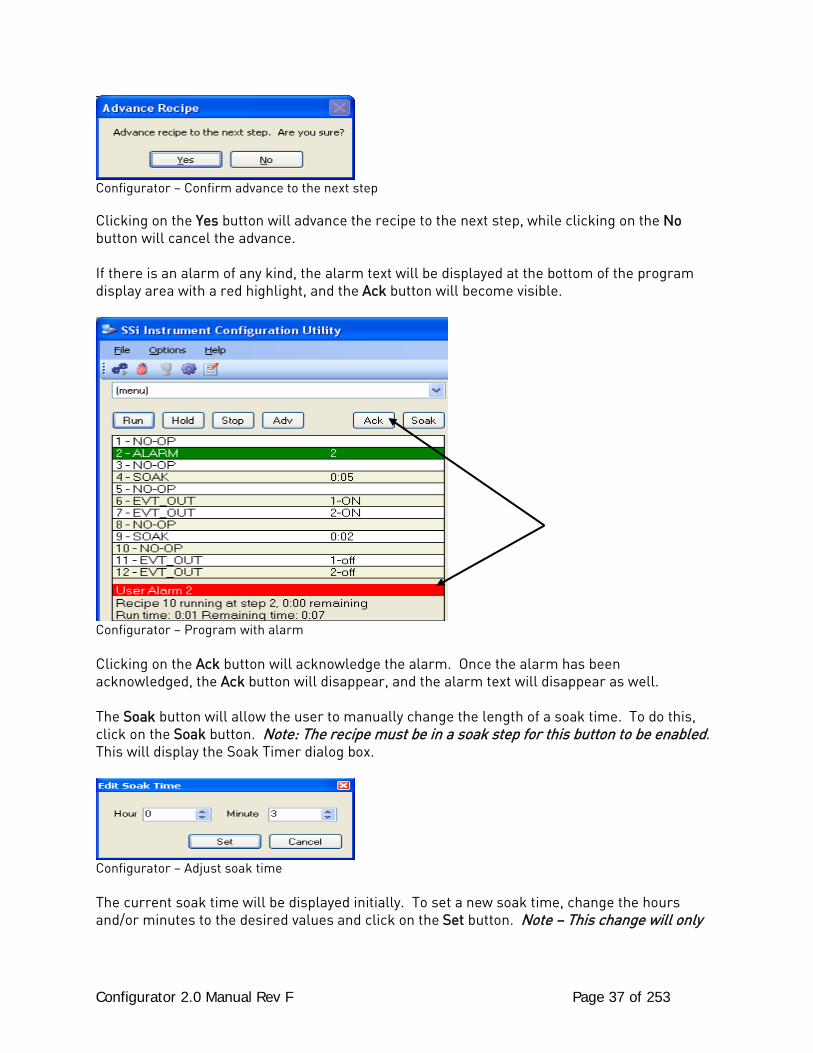
Configurator – Confirm advance to the next step Clicking on the Yes button will advance the recipe to the next step, while clicking on the No button will cancel the advance. If there is an alarm of any kind, the alarm text will be displayed at the bottom of the program display area with a red highlight, and the Ack button will become visible.
Configurator – Program with alarm Clicking on the Ack button will acknowledge the alarm. Once the alarm has been acknowledged, the Ack button will disappear, and the alarm text will disappear as well. The Soak button will allow the user to manually change the length of a soak time. To do this, click on the Soak button. Note: The recipe must be in a soak step for this button to be enabled. This will display the Soak Timer dialog box.
Configurator – Adjust soak time The current soak time will be displayed initially. To set a new soak time, change the hours and/or minutes to the desired values and click on the Set button. Note – This change will only
Configurator 2.0 Manual Rev F Page 38 of 253
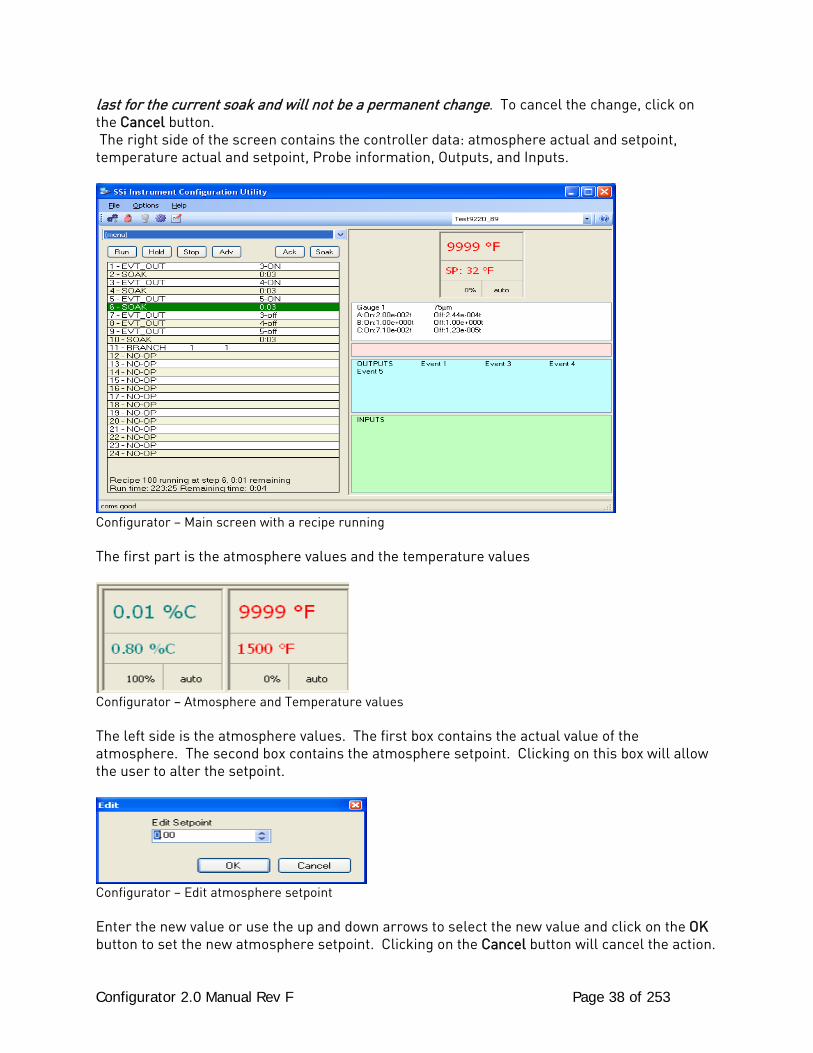
last for the current soak and will not be a permanent change. To cancel the change, click on the Cancel button. The right side of the screen contains the controller data: atmosphere actual and setpoint, temperature actual and setpoint, Probe information, Outputs, and Inputs.
Configurator – Main screen with a recipe running The first part is the atmosphere values and the temperature values
Configurator – Atmosphere and Temperature values The left side is the atmosphere values. The first box contains the actual value of the atmosphere. The second box contains the atmosphere setpoint. Clicking on this box will allow the user to alter the setpoint.
Configurator – Edit atmosphere setpoint Enter the new value or use the up and down arrows to select the new value and click on the OK button to set the new atmosphere setpoint. Clicking on the Cancel button will cancel the action.
Configurator 2.0 Manual Rev F Page 39 of 253
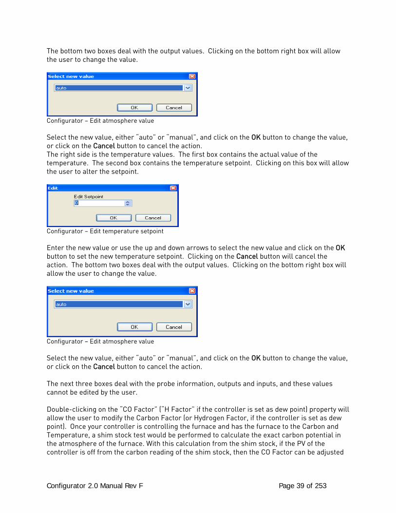
The bottom two boxes deal with the output values. Clicking on the bottom right box will allow the user to change the value.
Configurator – Edit atmosphere value Select the new value, either “auto” or “manual”, and click on the OK button to change the value, or click on the Cancel button to cancel the action. The right side is the temperature values. The first box contains the actual value of the temperature. The second box contains the temperature setpoint. Clicking on this box will allow the user to alter the setpoint.
Configurator – Edit temperature setpoint Enter the new value or use the up and down arrows to select the new value and click on the OK button to set the new temperature setpoint. Clicking on the Cancel button will cancel the action. The bottom two boxes deal with the output values. Clicking on the bottom right box will allow the user to change the value.
Configurator – Edit atmosphere value Select the new value, either “auto” or “manual”, and click on the OK button to change the value, or click on the Cancel button to cancel the action. The next three boxes deal with the probe information, outputs and inputs, and these values cannot be edited by the user. Double-clicking on the “CO Factor” (“H Factor” if the controller is set as dew point) property will allow the user to modify the Carbon Factor (or Hydrogen Factor, if the controller is set as dew point). Once your controller is controlling the furnace and has the furnace to the Carbon and Temperature, a shim stock test would be performed to calculate the exact carbon potential in the atmosphere of the furnace. With this calculation from the shim stock, if the PV of the controller is off from the carbon reading of the shim stock, then the CO Factor can be adjusted

Configurator 2.0 Manual Rev F Page 40 of 253
so that the PV for carbon will match the shim stock. The user would adjust the CO Factor up for a higher reading and down for a lower reading. On the Advantech touch screen this can be found under the Loops screen (there is a button for COF). The H2 Factor is the same as the CO Factor; only H2 is used for Dewpoint calculation instead of Carbon. This can be measured by a certified Dew point analyzer. You would adjust the H2 Factor up for a higher reading and down for a lower reading.
Configurator 2.0 Manual Rev F Page 41 of 253
9200 Firmware Upgrade Procedure i. Overview
The series 9200 firmware may require upgrades as determined by Super Systems Inc. These upgrades can be performed at SSI or they may also be performed at your facility while in use. The series 9200 will not maintain control of your system while this upgrade takes place and all precautions must taken prior to beginning this procedure. ii. Equipment Required
• A PC with an Ethernet port and a cross over cable • The Super Systems Configurator software e • The LocateIP software • The Serial Number Utility software • The UDP Download software • A PC with an Ethernet port and a crossover cable is required. The Super Systems
Configurator software, the LocateIP software, the Serial Number Utility software and the UDP Download software are all required.
iii. Instructions 1 – Go To, or start, the Configurator program on your PC. 2 - The Configurator has a toolbar menu in the upper left. From left to right the icons will be referred to as:
A) Connect ( ) B) Login ( ) C) Show Overview Display ( )
D) System Settings ( ) E) Edit Recipes ( ) 3 - Click the Login icon ( ) Enter the password obtained from Super Systems Inc. for that day into the “Password” text box on the login form. No username is required when logging in as SSi Special. Click on the “OK” button. If the login was successful, the lock will change to a red lock ( ). NOTE: If you have only one (1) 9200 previously connected and running you can “SKIP” Steps No. 4, 5, 6, 7, 8 & 9.
4 - Click the System Settings icon ( ), then click the “Add” button. This will display the System Management form.
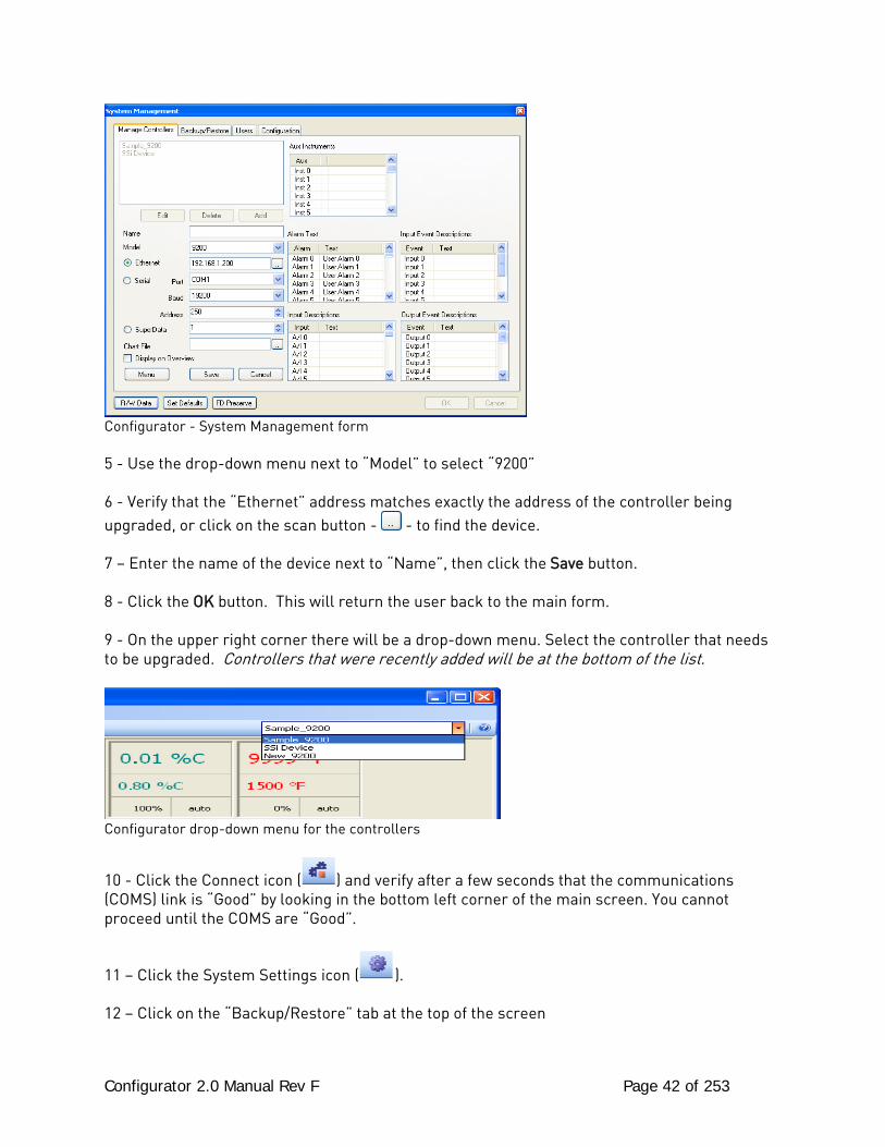
Configurator 2.0 Manual Rev F Page 42 of 253
Configurator - System Management form 5 - Use the drop-down menu next to “Model” to select “9200” 6 - Verify that the “Ethernet” address matches exactly the address of the controller being upgraded, or click on the scan button - - to find the device. 7 – Enter the name of the device next to “Name”, then click the Save button. 8 - Click the OK button. This will return the user back to the main form. 9 - On the upper right corner there will be a drop-down menu. Select the controller that needs to be upgraded. Controllers that were recently added will be at the bottom of the list.
Configurator drop-down menu for the controllers
10 - Click the Connect icon ( ) and verify after a few seconds that the communications (COMS) link is “Good” by looking in the bottom left corner of the main screen. You cannot proceed until the COMS are “Good”.
11 – Click the System Settings icon ( ). 12 – Click on the “Backup/Restore” tab at the top of the screen
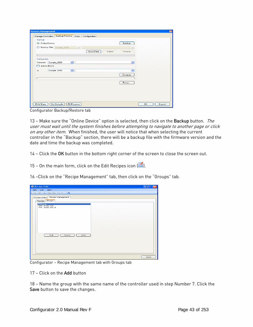
Configurator 2.0 Manual Rev F Page 43 of 253
Configurator Backup/Restore tab 13 – Make sure the “Online Device” option is selected, then click on the Backup button. The user must wait until the system finishes before attempting to navigate to another page or click on any other item. When finished, the user will notice that when selecting the current controller in the “Backup” section, there will be a backup file with the firmware version and the date and time the backup was completed. 14 – Click the OK button in the bottom right corner of the screen to close the screen out. 15 – On the main form, click on the Edit Recipes icon ( ). 16 –Click on the “Recipe Management” tab, then click on the “Groups” tab.
Configurator – Recipe Management tab with Groups tab 17 – Click on the Add button 18 – Name the group with the same name of the controller used in step Number 7. Click the Save button to save the changes.
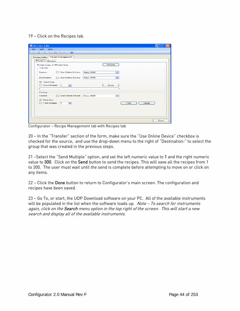
Configurator 2.0 Manual Rev F Page 44 of 253
19 – Click on the Recipes tab.
Configurator – Recipe Management tab with Recipes tab 20 – In the “Transfer” section of the form, make sure the “Use Online Device” checkbox is checked for the source, and use the drop-down menu to the right of “Destination:” to select the group that was created in the previous steps. 21 –Select the “Send Multiple” option, and set the left numeric value to 1 and the right numeric value to 300. Click on the Send button to send the recipes. This will save all the recipes from 1 to 300. The user must wait until the send is complete before attempting to move on or click on any items. 22 – Click the Done button to return to Configurator’s main screen. The configuration and recipes have been saved. 23 – Go To, or start, the UDP Download software on your PC. All of the available instruments will be populated in the list when the software loads up. Note – To search for instruments again, click on the Search menu option in the top right of the screen. This will start a new search and display all of the available instruments.
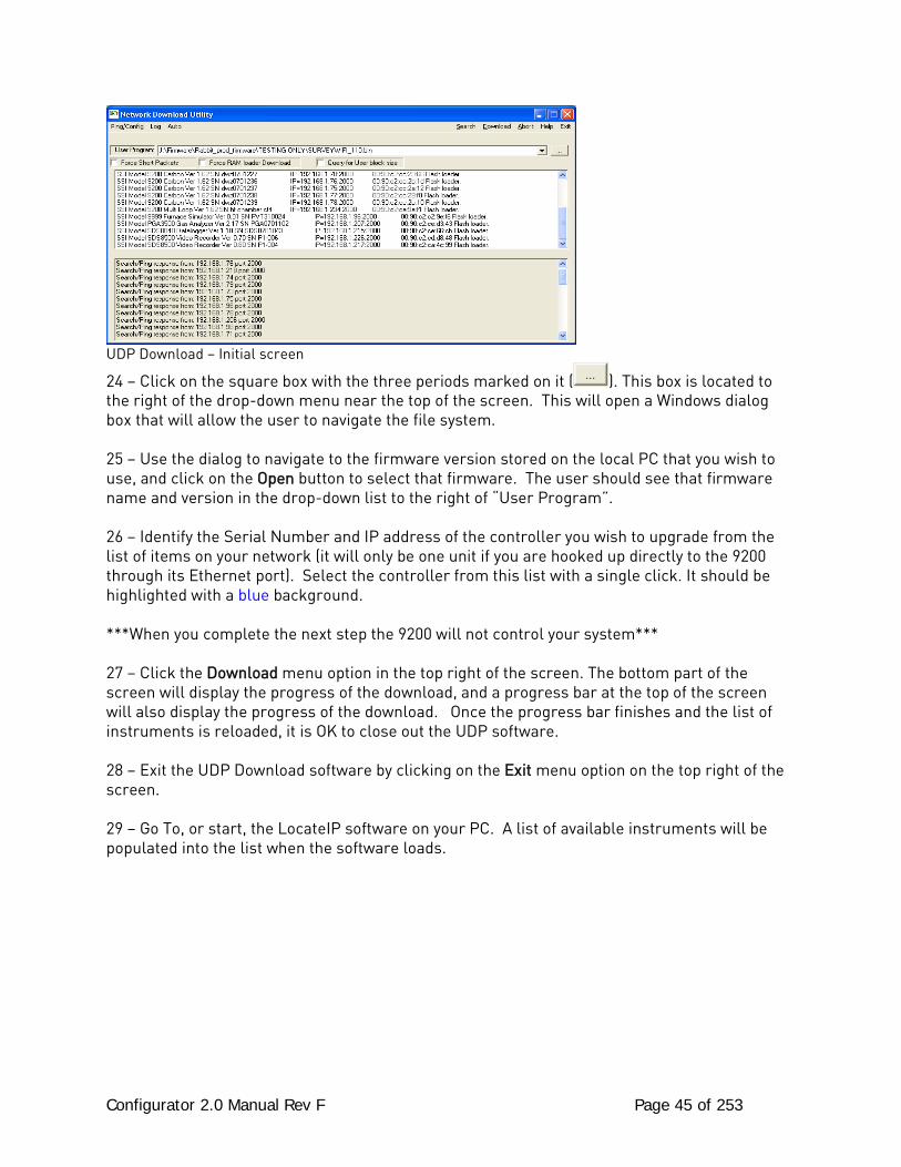
Configurator 2.0 Manual Rev F Page 45 of 253
UDP Download – Initial screen
24 – Click on the square box with the three periods marked on it ( ). This box is located to the right of the drop-down menu near the top of the screen. This will open a Windows dialog box that will allow the user to navigate the file system. 25 – Use the dialog to navigate to the firmware version stored on the local PC that you wish to use, and click on the Open button to select that firmware. The user should see that firmware name and version in the drop-down list to the right of “User Program”. 26 – Identify the Serial Number and IP address of the controller you wish to upgrade from the list of items on your network (it will only be one unit if you are hooked up directly to the 9200 through its Ethernet port). Select the controller from this list with a single click. It should be highlighted with a blue background. ***When you complete the next step the 9200 will not control your system*** 27 – Click the Download menu option in the top right of the screen. The bottom part of the screen will display the progress of the download, and a progress bar at the top of the screen will also display the progress of the download. Once the progress bar finishes and the list of instruments is reloaded, it is OK to close out the UDP software. 28 – Exit the UDP Download software by clicking on the Exit menu option on the top right of the screen. 29 – Go To, or start, the LocateIP software on your PC. A list of available instruments will be populated into the list when the software loads.
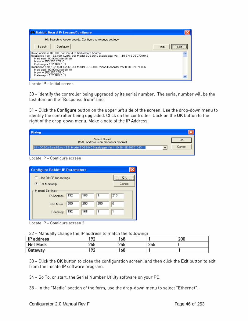
Configurator 2.0 Manual Rev F Page 46 of 253
Locate IP – Initial screen 30 – Identify the controller being upgraded by its serial number. The serial number will be the last item on the “Response from” line. 31 – Click the Configure button on the upper left side of the screen. Use the drop-down menu to identify the controller being upgraded. Click on the controller. Click on the OK button to the right of the drop-down menu. Make a note of the IP Address.
Locate IP – Configure screen
Locate IP – Configure screen 2 32 – Manually change the IP address to match the following:
IP address 192 168 1 200 Net Mask 255 255 255 0 Gateway 192 168 1 1 33 – Click the OK button to close the configuration screen, and then click the Exit button to exit from the Locate IP software program. 34 – Go To, or start, the Serial Number Utility software on your PC. 35 – In the “Media” section of the form, use the drop-down menu to select “Ethernet”.
Configurator 2.0 Manual Rev F Page 47 of 253
36 - In the box below, select the controller being upgraded by identifying the serial number and IP address. Click on the controller to highlight it. 37 – click “Yes” in the “Date And Time” section of the form. 38 – In the “Load Default Configuration” section of the form, use the pull-down menu to select which type of controller is being used. 39 – Click on the Load button. A message box will appear asking you if you want to reset the instrument to factory defaults. Click the YES button. You will get an error message stating “Unable to Reset Instrument to Factory Defaults”. Ignore this error. 40 – Wait 20 seconds. 41 – Click the Scan button in the upper right corner of the form. Identify the controller being upgraded by its serial number. The IP address will have changed to the factory default address of: 192.168.0.200 42 – Click the Done button to exit the Serial Number Utility software. 43 – Go To, or start, the Locate IP software on your PC. 44 – Click the Configure button on the upper left side of the form. Use the drop-down menu to identify the controller being upgraded. Click on the controller. Click the OK button to the right of the drop-down menu. 45 – Manually change the IP address to match the same address noted in Step Number 31. 49 – Click the OK button, then click the Exit button on the Locate IP software program. 50 – Select the controller that is being upgraded from the drop-down list and click on the
connect icon ( ).
50 – Using the series 9200 Configurator Software, click on the System Settings ( ) icon. 51 – Click on the “Backup/Restore” tab near the top of the screen. 52 –In the “Backup” section of the form, make sure the “Backup Files” option is selected and select the group/file you wish to restore. 53 – Click the Restore button. A message box will appear asking the user to confirm the restoration of the instrument to the selected backup. Click the Yes button. It is important to wait until the restoration is complete before trying to navigate away from this page or click on any items. *** The 9200 will regain control after the next step is complete***
Configurator 2.0 Manual Rev F Page 48 of 253
54 – Click the OK button. 55 – On the main form, click on the “Edit Recipes” icon ( ). 56 – Click on the “Recipe Management” tab. Make sure the “Recipes” tab is selected. 57 – In the “Transfer” section of the form, use the drop-down menu to the right of “Source” to select the group used in Step Number 20. 58 - Make sure the “Use Online Device” is checked so that the “Destination” will be the upgraded controller. 59 – Make sure the “Send Multiple” option is selected. Make the left numeric value box 1, and make the right numeric value box 300. This will restore all the recipes from 1 to 300. 60 – Click the Send button. The user must wait until the status bar is complete and all 300 recipes have been restored before attempting to move on or click on any items. 63 – Click the Done button to return to Configurator’s main form. The configuration and recipes have been restored. 64 - Using the Analog Input Setup section of the Super Systems Inc. Configurator, manually change Input 1 type to 1.25 volts. 65 – Exit the Super Systems Inc. Configurator software.
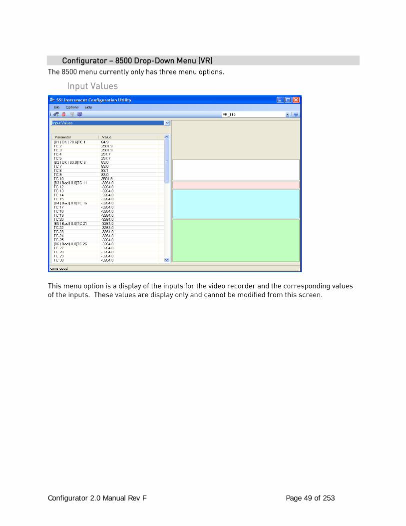
Configurator 2.0 Manual Rev F Page 49 of 253
Configurator – 8500 Drop-Down Menu (VR) The 8500 menu currently only has three menu options.
Input Values
This menu option is a display of the inputs for the video recorder and the corresponding values of the inputs. These values are display only and cannot be modified from this screen.
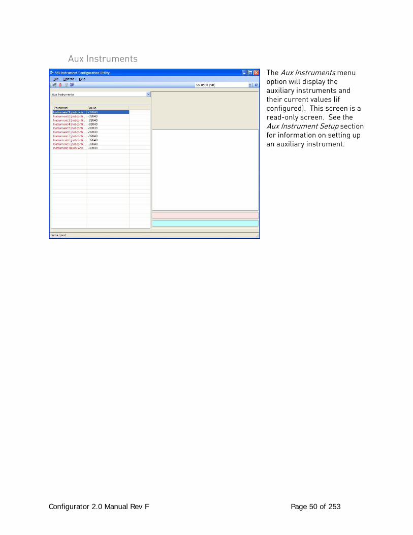
Configurator 2.0 Manual Rev F Page 50 of 253
Aux Instruments The Aux Instruments menu option will display the auxiliary instruments and their current values (if configured). This screen is a read-only screen. See the Aux Instrument Setup section for information on setting up an auxiliary instrument.

Configurator 2.0 Manual Rev F Page 51 of 253
Communication Setup The Communication Setup menu option will allow the user to set up the communications parameters for the Video Recorder. Host 232 Baud This option will allow the user to set the Host 232 baud rate. The options are: 1200 2400 4800 9600 14400 19200 28800 38400 57600 76800 115200 Slave 232 Baud This option will allow the user to set the Slave 232 baud rate. The options are: 1200 19200 115200 2400 28800 4800 38400 9600 57600 14400 76800 Host 485 Baud This option will allow the user to set the Host 485 baud rate. The options are: 1200 19200 115200 2400 28800 4800 38400 9600 57600 14400 76800 Host 485 Address This option will allow the user to set the Host 485 address. The range is 1 through 249. Slave 1 (5,6) Baud This option will allow the user to set the Slave 1 baud rate. The options are: 1200 19200 115200
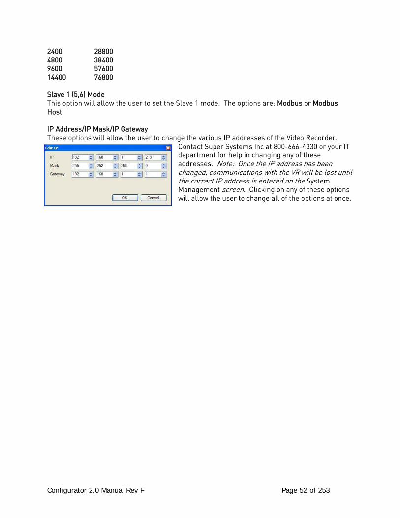
Configurator 2.0 Manual Rev F Page 52 of 253
2400 28800 4800 38400 9600 57600 14400 76800 Slave 1 (5,6) Mode This option will allow the user to set the Slave 1 mode. The options are: Modbus or Modbus Host IP Address/IP Mask/IP Gateway These options will allow the user to change the various IP addresses of the Video Recorder.
Contact Super Systems Inc at 800-666-4330 or your IT department for help in changing any of these addresses. Note: Once the IP address has been changed, communications with the VR will be lost until the correct IP address is entered on the System Management screen. Clicking on any of these options will allow the user to change all of the options at once.
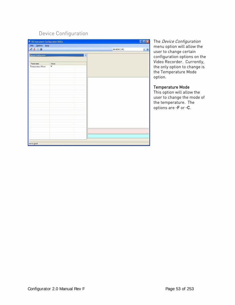
Configurator 2.0 Manual Rev F Page 53 of 253
Device Configuration The Device Configuration menu option will allow the user to change certain configuration options on the Video Recorder. Currently, the only option to change is the Temperature Mode option. Temperature Mode This option will allow the user to change the mode of the temperature. The options are ◦F or ◦C.
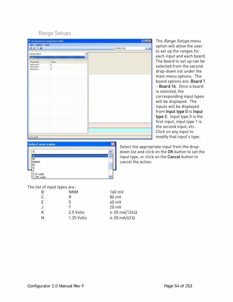
Configurator 2.0 Manual Rev F Page 54 of 253
Range Setups The Range Setups menu option will allow the user to set up the ranges for each input and each board. The board to set up can be selected from the second drop-down list under the main menu options. The board options are: Board 1 – Board 16. Once a board is selected, the corresponding input types will be displayed. The inputs will be displayed from Input type 0 to Input type 2. Input type 0 is the first input, input type 1 is the second input, etc. Click on any input to modify that input’s type.
Select the appropriate input from the drop-down list and click on the OK button to set the input type, or click on the Cancel button to cancel the action.
The list of input types are: B NNM 160 mV C R 80 mV E S 40 mV J T 20 mV K 2.5 Volts 4-20 mA/124Ω N 1.25 Volts 4-20 mA/62Ω
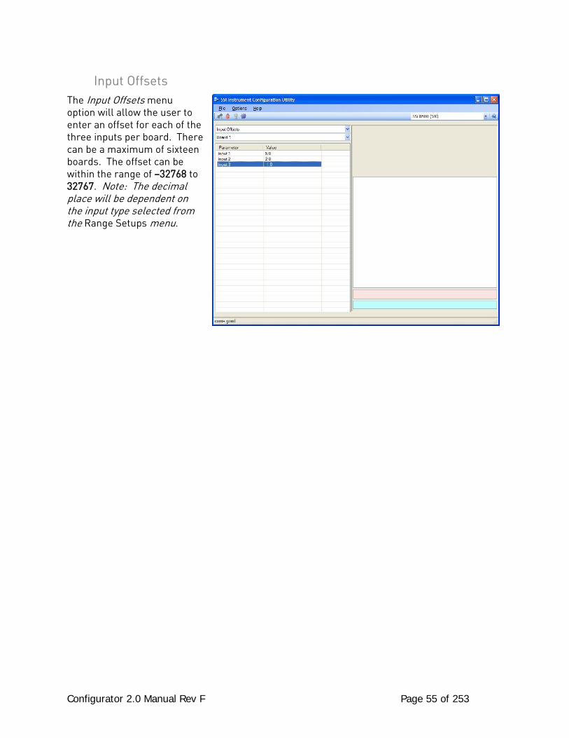
Configurator 2.0 Manual Rev F Page 55 of 253
Input Offsets The Input Offsets menu option will allow the user to enter an offset for each of the three inputs per board. There can be a maximum of sixteen boards. The offset can be within the range of –32768 to 32767. Note: The decimal place will be dependent on the input type selected from the Range Setups menu.
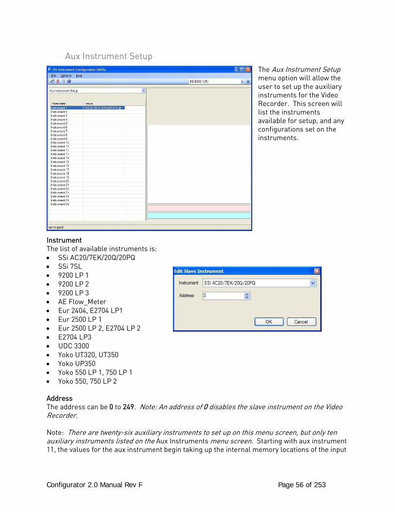
Configurator 2.0 Manual Rev F Page 56 of 253
Aux Instrument Setup The Aux Instrument Setup menu option will allow the user to set up the auxiliary instruments for the Video Recorder. This screen will list the instruments available for setup, and any configurations set on the instruments.
Instrument The list of available instruments is: • SSi AC20/7EK/20Q/20PQ • SSi 7SL • 9200 LP 1 • 9200 LP 2 • 9200 LP 3 • AE Flow_Meter • Eur 2404, E2704 LP1 • Eur 2500 LP 1 • Eur 2500 LP 2, E2704 LP 2 • E2704 LP3 • UDC 3300 • Yoko UT320, UT350 • Yoko UP350 • Yoko 550 LP 1, 750 LP 1 • Yoko 550, 750 LP 2 Address The address can be 0 to 249. Note: An address of 0 disables the slave instrument on the Video Recorder. Note: There are twenty-six auxiliary instruments to set up on this menu screen, but only ten auxiliary instruments listed on the Aux Instruments menu screen. Starting with aux instrument 11, the values for the aux instrument begin taking up the internal memory locations of the input

Configurator 2.0 Manual Rev F Page 57 of 253
boards, starting with board 16: Aux instrument 11 replaces board 16; aux instrument 12 replaces board 15, etc.
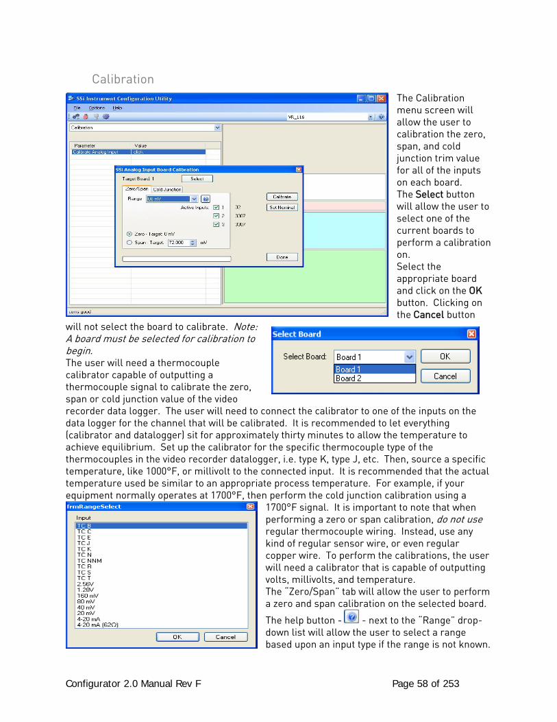
Configurator 2.0 Manual Rev F Page 58 of 253
Calibration The Calibration menu screen will allow the user to calibration the zero, span, and cold junction trim value for all of the inputs on each board. The Select button will allow the user to select one of the current boards to perform a calibration on. Select the appropriate board and click on the OK button. Clicking on the Cancel button
will not select the board to calibrate. Note: A board must be selected for calibration to begin. The user will need a thermocouple calibrator capable of outputting a thermocouple signal to calibrate the zero, span or cold junction value of the video recorder data logger. The user will need to connect the calibrator to one of the inputs on the data logger for the channel that will be calibrated. It is recommended to let everything (calibrator and datalogger) sit for approximately thirty minutes to allow the temperature to achieve equilibrium. Set up the calibrator for the specific thermocouple type of the thermocouples in the video recorder datalogger, i.e. type K, type J, etc. Then, source a specific temperature, like 1000°F, or millivolt to the connected input. It is recommended that the actual temperature used be similar to an appropriate process temperature. For example, if your equipment normally operates at 1700°F, then perform the cold junction calibration using a
1700°F signal. It is important to note that when performing a zero or span calibration, do not use regular thermocouple wiring. Instead, use any kind of regular sensor wire, or even regular copper wire. To perform the calibrations, the user will need a calibrator that is capable of outputting volts, millivolts, and temperature. The “Zero/Span” tab will allow the user to perform a zero and span calibration on the selected board.
The help button - - next to the “Range” drop-down list will allow the user to select a range based upon an input type if the range is not known.
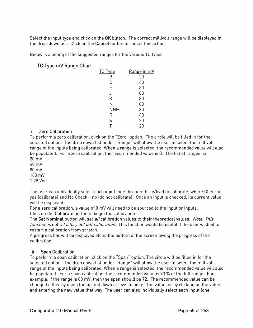
Configurator 2.0 Manual Rev F Page 59 of 253
Select the input type and click on the OK button. The correct millivolt range will be displayed in the drop-down list. Click on the Cancel button to cancel this action. Below is a listing of the suggested ranges for the various TC types. TC Type mV Range Chart
TC Type Range in mV B 20 C 40 E 80 J 80 K 80 N 80 NNM 80 R 40 S 20 T 20
i. Zero Calibration To perform a zero calibration, click on the “Zero” option. The circle will be filled in for the selected option. The drop down list under “Range” will allow the user to select the millivolt range of the inputs being calibrated. When a range is selected, the recommended value will also be populated. For a zero calibration, the recommended value is 0. The list of ranges is: 20 mV 40 mV 80 mV 160 mV 1.28 Volt The user can individually select each input (one through three/five) to calibrate, where Check = yes (calibrate) and No Check = no (do not calibrate). Once an input is checked, its current value will be displayed. For a zero calibration, a value of 0 mV will need to be sourced to the input or inputs. Click on the Calibrate button to begin the calibration. The Set Nominal button will set all calibration values to their theoretical values. Note: This function is not a factory default calibration. This function would be useful if the user wished to restart a calibration from scratch. A progress bar will be displayed along the bottom of the screen giving the progress of the calibration. ii. Span Calibration
To perform a span calibration, click on the “Span” option. The circle will be filled in for the selected option. The drop down list under “Range” will allow the user to select the millivolt range of the inputs being calibrated. When a range is selected, the recommended value will also be populated. For a span calibration, the recommended value is 90 % of the full range. For example, if the range is 80 mV, then the span should be 72. The recommended value can be changed either by using the up and down arrows to adjust the value, or by clicking on the value, and entering the new value that way. The user can also individually select each input (one
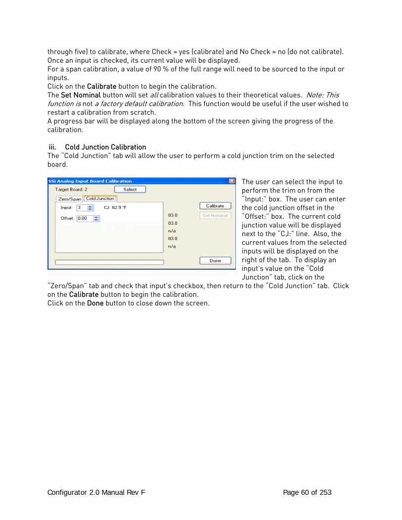
Configurator 2.0 Manual Rev F Page 60 of 253
through five) to calibrate, where Check = yes (calibrate) and No Check = no (do not calibrate). Once an input is checked, its current value will be displayed. For a span calibration, a value of 90 % of the full range will need to be sourced to the input or inputs. Click on the Calibrate button to begin the calibration. The Set Nominal button will set all calibration values to their theoretical values. Note: This function is not a factory default calibration. This function would be useful if the user wished to restart a calibration from scratch. A progress bar will be displayed along the bottom of the screen giving the progress of the calibration. iii. Cold Junction Calibration The “Cold Junction” tab will allow the user to perform a cold junction trim on the selected board.
The user can select the input to perform the trim on from the “Input:” box. The user can enter the cold junction offset in the “Offset:” box. The current cold junction value will be displayed next to the “CJ:” line. Also, the current values from the selected inputs will be displayed on the right of the tab. To display an input’s value on the “Cold Junction” tab, click on the
“Zero/Span” tab and check that input’s checkbox, then return to the “Cold Junction” tab. Click on the Calibrate button to begin the calibration. Click on the Done button to close down the screen.
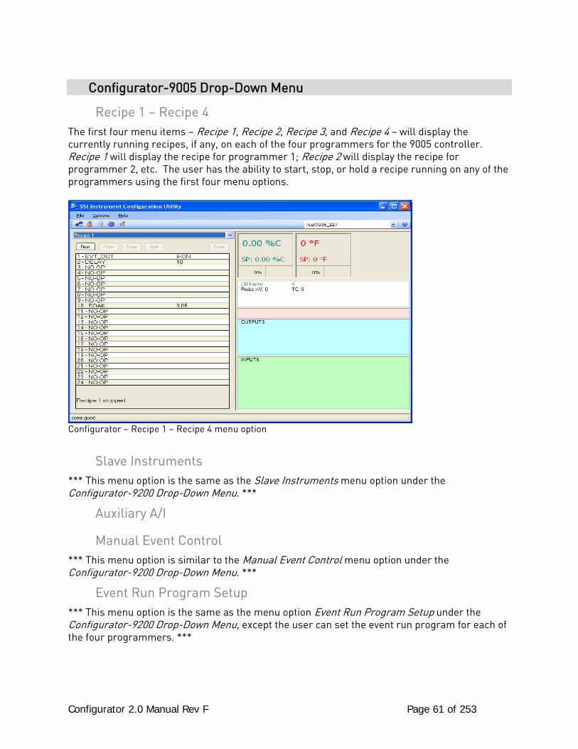
Configurator 2.0 Manual Rev F Page 61 of 253
Configurator-9005 Drop-Down Menu
Recipe 1 – Recipe 4 The first four menu items – Recipe 1, Recipe 2, Recipe 3, and Recipe 4 – will display the currently running recipes, if any, on each of the four programmers for the 9005 controller. Recipe 1 will display the recipe for programmer 1; Recipe 2 will display the recipe for programmer 2, etc. The user has the ability to start, stop, or hold a recipe running on any of the programmers using the first four menu options.
Configurator – Recipe 1 – Recipe 4 menu option
Slave Instruments *** This menu option is the same as the Slave Instruments menu option under the Configurator-9200 Drop-Down Menu. ***
Auxiliary A/I
Manual Event Control *** This menu option is similar to the Manual Event Control menu option under the Configurator-9200 Drop-Down Menu. ***
Event Run Program Setup *** This menu option is the same as the menu option Event Run Program Setup under the Configurator-9200 Drop-Down Menu, except the user can set the event run program for each of the four programmers. ***
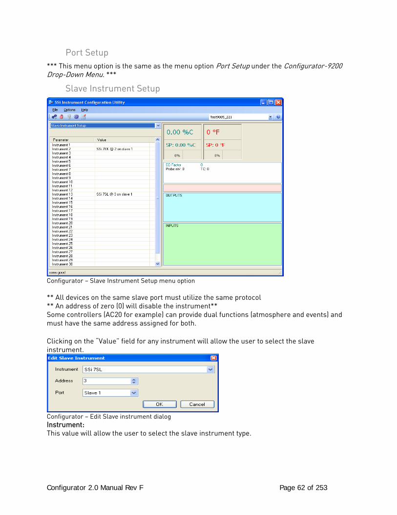
Configurator 2.0 Manual Rev F Page 62 of 253
Port Setup *** This menu option is the same as the menu option Port Setup under the Configurator-9200 Drop-Down Menu. ***
Slave Instrument Setup
Configurator – Slave Instrument Setup menu option ** All devices on the same slave port must utilize the same protocol ** An address of zero (0) will disable the instrument** Some controllers (AC20 for example) can provide dual functions (atmosphere and events) and must have the same address assigned for both. Clicking on the “Value” field for any instrument will allow the user to select the slave instrument.
Configurator – Edit Slave instrument dialog Instrument: This value will allow the user to select the slave instrument type.
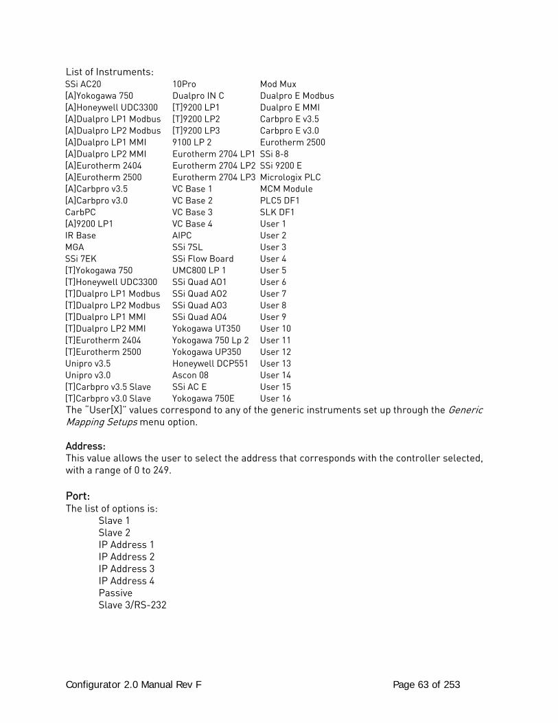
Configurator 2.0 Manual Rev F Page 63 of 253
List of Instruments: SSi AC20 10Pro Mod Mux [A]Yokogawa 750 Dualpro IN C Dualpro E Modbus [A]Honeywell UDC3300 [T]9200 LP1 Dualpro E MMI [A]Dualpro LP1 Modbus [T]9200 LP2 Carbpro E v3.5 [A]Dualpro LP2 Modbus [T]9200 LP3 Carbpro E v3.0 [A]Dualpro LP1 MMI 9100 LP 2 Eurotherm 2500 [A]Dualpro LP2 MMI Eurotherm 2704 LP1 SSi 8-8 [A]Eurotherm 2404 Eurotherm 2704 LP2 SSi 9200 E [A]Eurotherm 2500 Eurotherm 2704 LP3 Micrologix PLC [A]Carbpro v3.5 VC Base 1 MCM Module [A]Carbpro v3.0 VC Base 2 PLC5 DF1 CarbPC VC Base 3 SLK DF1 [A]9200 LP1 VC Base 4 User 1 IR Base AIPC User 2 MGA SSi 7SL User 3 SSi 7EK SSi Flow Board User 4 [T]Yokogawa 750 UMC800 LP 1 User 5 [T]Honeywell UDC3300 SSi Quad AO1 User 6 [T]Dualpro LP1 Modbus SSi Quad AO2 User 7 [T]Dualpro LP2 Modbus SSi Quad AO3 User 8 [T]Dualpro LP1 MMI SSi Quad AO4 User 9 [T]Dualpro LP2 MMI Yokogawa UT350 User 10 [T]Eurotherm 2404 Yokogawa 750 Lp 2 User 11 [T]Eurotherm 2500 Yokogawa UP350 User 12 Unipro v3.5 Honeywell DCP551 User 13 Unipro v3.0 Ascon 08 User 14 [T]Carbpro v3.5 Slave SSi AC E User 15 [T]Carbpro v3.0 Slave Yokogawa 750E User 16 The “User[X]” values correspond to any of the generic instruments set up through the Generic Mapping Setups menu option. Address: This value allows the user to select the address that corresponds with the controller selected, with a range of 0 to 249. Port: The list of options is: Slave 1 Slave 2 IP Address 1 IP Address 2 IP Address 3 IP Address 4 Passive Slave 3/RS-232
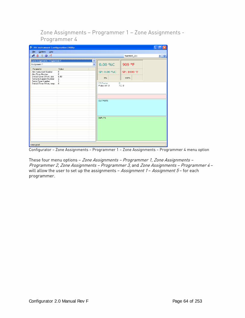
Configurator 2.0 Manual Rev F Page 64 of 253
Zone Assignments – Programmer 1 – Zone Assignments - Programmer 4
Configurator – Zone Assignments – Programmer 1 – Zone Assignments – Programmer 4 menu option These four menu options – Zone Assignments – Programmer 1, Zone Assignments – Programmer 2, Zone Assignments – Programmer 3, and Zone Assignments – Programmer 4 – will allow the user to set up the assignments – Assignment 1 – Assignment 5 – for each programmer.
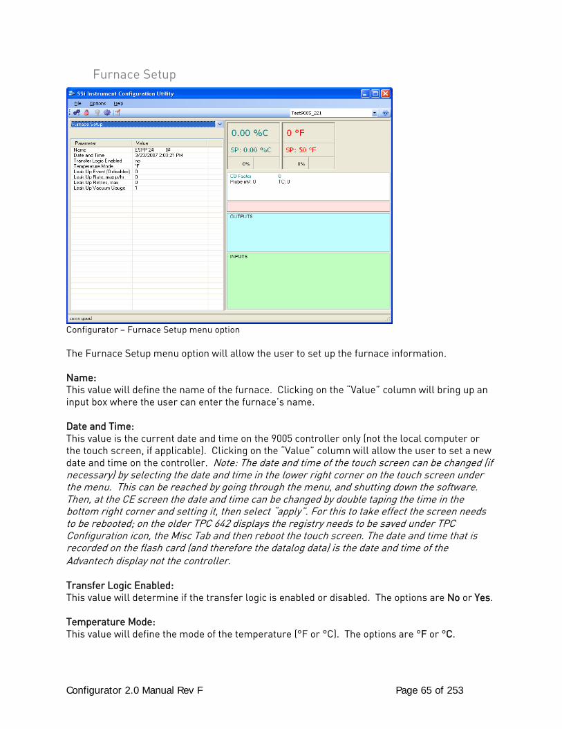
Configurator 2.0 Manual Rev F Page 65 of 253
Furnace Setup
Configurator – Furnace Setup menu option The Furnace Setup menu option will allow the user to set up the furnace information. Name: This value will define the name of the furnace. Clicking on the “Value” column will bring up an input box where the user can enter the furnace’s name. Date and Time: This value is the current date and time on the 9005 controller only (not the local computer or the touch screen, if applicable). Clicking on the “Value” column will allow the user to set a new date and time on the controller. Note: The date and time of the touch screen can be changed (if necessary) by selecting the date and time in the lower right corner on the touch screen under the menu. This can be reached by going through the menu, and shutting down the software. Then, at the CE screen the date and time can be changed by double taping the time in the bottom right corner and setting it, then select “apply”. For this to take effect the screen needs to be rebooted; on the older TPC 642 displays the registry needs to be saved under TPC Configuration icon, the Misc Tab and then reboot the touch screen. The date and time that is recorded on the flash card (and therefore the datalog data) is the date and time of the Advantech display not the controller. Transfer Logic Enabled: This value will determine if the transfer logic is enabled or disabled. The options are No or Yes. Temperature Mode: This value will define the mode of the temperature (°F or °C). The options are °F or °C.
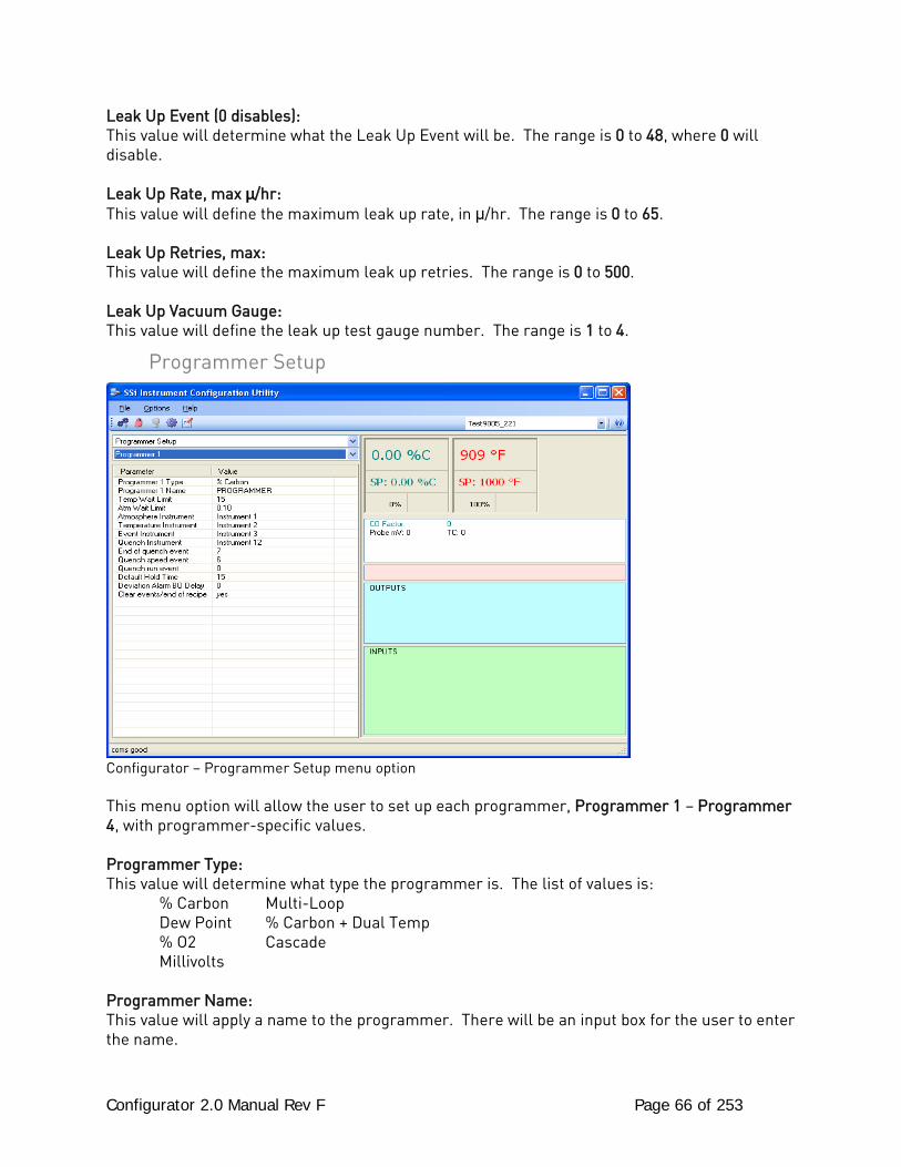
Configurator 2.0 Manual Rev F Page 66 of 253
Leak Up Event (0 disables): This value will determine what the Leak Up Event will be. The range is 0 to 48, where 0 will disable. Leak Up Rate, max μ/hr: This value will define the maximum leak up rate, in μ/hr. The range is 0 to 65. Leak Up Retries, max: This value will define the maximum leak up retries. The range is 0 to 500. Leak Up Vacuum Gauge: This value will define the leak up test gauge number. The range is 1 to 4.
Programmer Setup
Configurator – Programmer Setup menu option This menu option will allow the user to set up each programmer, Programmer 1 – Programmer 4, with programmer-specific values. Programmer Type: This value will determine what type the programmer is. The list of values is: % Carbon Multi-Loop Dew Point % Carbon + Dual Temp % O2 Cascade Millivolts Programmer Name: This value will apply a name to the programmer. There will be an input box for the user to enter the name.
Configurator 2.0 Manual Rev F Page 67 of 253
Temp Wait Limit: This value will define the temperature wait limit. The range is 0 to 4000. Atm Wait Limit: This value will define the atmosphere wait limit. The range is 0.00 to 40.00. Atmosphere Instrument: This value will define which instrument will be the atmosphere instrument. The list of choices is: Instrument 1 through Instrument 25. Temperature Instrument: This value will define which instrument will be the temperature instrument. The list of choices is: Instrument 1 through Instrument 25. Event Instrument: This value will define which instrument will be the event instrument. The list of choices is: Instrument 1 through Instrument 25. Quench Instrument: This value will define which instrument will be the quench instrument. The list of choices is: Instrument 1 through Instrument 25. End of Quench Event: This value will define which event will signify the end of Quench. The list of options is: 0 to 14. Quench Speed Event: This value will define which event will signify the Quench Speed event. The list of options is: 0 to 14. Quench Run Event: This value will define which event will signify the Quench Run event. The list of options is: 0 to 14. Default Hold Time: This value will define the default hold time, in minutes. The range is 0 to 10000. Deviation Alarm BO Delay: This value will define the deviation alarm’s burnoff delay, in minutes. The range is 0 to 10000. Clear events/end of recipe: This value will determine whether the events will be cleared at the end of a recipe. The possible choices are no and yes.
Passcode and Alarm *** This menu option is the same as the Passcode and Alarm menu option under the Configurator-9200 Drop Down Menu. ***

Configurator 2.0 Manual Rev F Page 68 of 253
IP Address *** This menu option is the same as the IP Address menu option under the Configurator-9200 Drop Down Menu. ***
Zone/Load TC Setup *** This menu option is the same as the menu option Zone/Load TC Setup under the Configurator-9200 Drop-Down Menu. ***
Event Control
Configurator – Event Control menu option The Event control provides the user manual control of actual event outputs for each of the four programmers. This is useful when testing wiring and field devices. Hold Instrument Number: Clicking on this value will display an input box from which the user can select a new value. The range is 0 to 32. Hold Minimum PV: Clicking on this value will display an input box from which the user can select a new value. The range is 0 to 4000. Hold Maximum PV: Clicking on this value will display an input box from which the user can select a new value. The range is 0 to 4000. Event for Program Run: Clicking on this value will display an input box from which the user can select a new value. The range is –1 to 15.
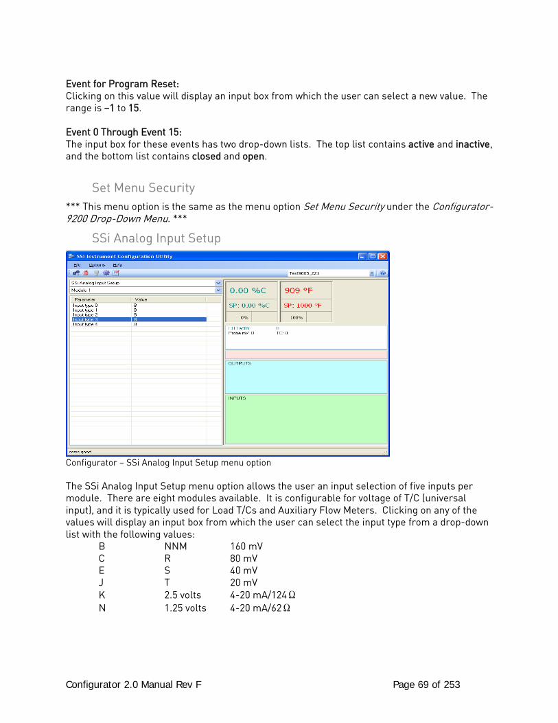
Configurator 2.0 Manual Rev F Page 69 of 253
Event for Program Reset: Clicking on this value will display an input box from which the user can select a new value. The range is –1 to 15. Event 0 Through Event 15: The input box for these events has two drop-down lists. The top list contains active and inactive, and the bottom list contains closed and open.
Set Menu Security *** This menu option is the same as the menu option Set Menu Security under the Configurator-9200 Drop-Down Menu. ***
SSi Analog Input Setup
Configurator – SSi Analog Input Setup menu option The SSi Analog Input Setup menu option allows the user an input selection of five inputs per module. There are eight modules available. It is configurable for voltage of T/C (universal input), and it is typically used for Load T/Cs and Auxiliary Flow Meters. Clicking on any of the values will display an input box from which the user can select the input type from a drop-down list with the following values: B NNM 160 mV C R 80 mV E S 40 mV J T 20 mV K 2.5 volts 4-20 mA/124Ω N 1.25 volts 4-20 mA/62Ω
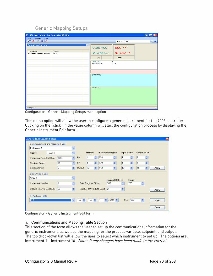
Configurator 2.0 Manual Rev F Page 70 of 253
Generic Mapping Setups
Configurator – Generic Mapping Setups menu option This menu option will allow the user to configure a generic instrument for the 9005 controller. Clicking on the “click” in the value column will start the configuration process by displaying the Generic Instrument Edit form.
Configurator – Generic Instrument Edit form i. Communications and Mapping Table Section
This section of the form allows the user to set up the communications information for the generic instrument, as well as the mapping for the process variable, setpoint, and output. The top drop-down list will allow the user to select which instrument to set up. The options are: Instrument 1 – Instrument 16. Note: If any changes have been made to the current
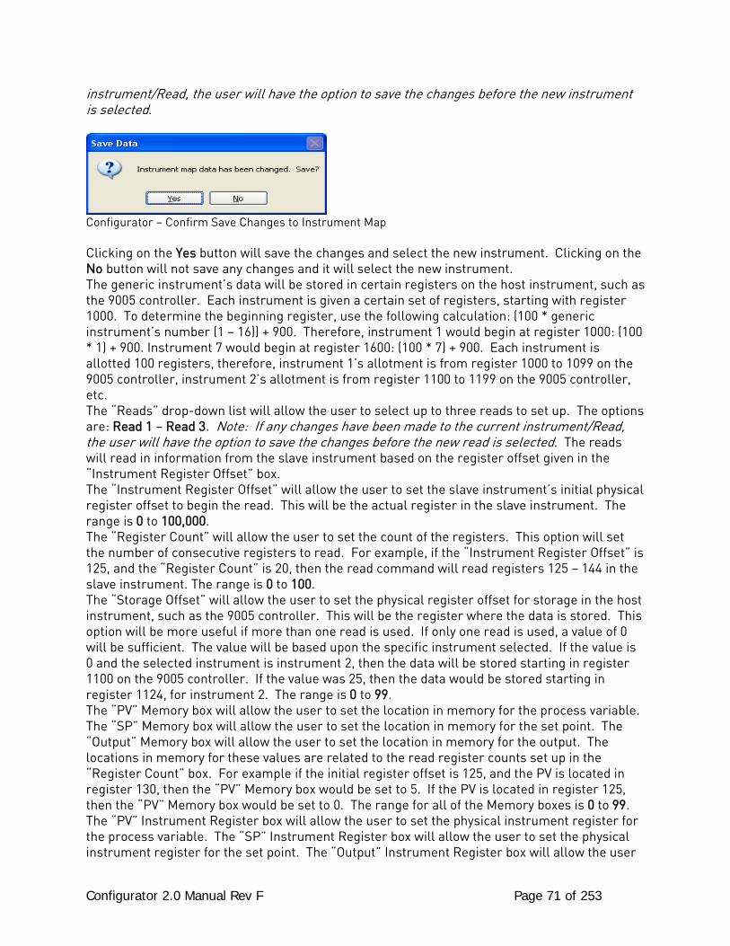
Configurator 2.0 Manual Rev F Page 71 of 253
instrument/Read, the user will have the option to save the changes before the new instrument is selected.
Configurator – Confirm Save Changes to Instrument Map Clicking on the Yes button will save the changes and select the new instrument. Clicking on the No button will not save any changes and it will select the new instrument. The generic instrument’s data will be stored in certain registers on the host instrument, such as the 9005 controller. Each instrument is given a certain set of registers, starting with register 1000. To determine the beginning register, use the following calculation: (100 * generic instrument’s number (1 – 16)) + 900. Therefore, instrument 1 would begin at register 1000: (100 * 1) + 900. Instrument 7 would begin at register 1600: (100 * 7) + 900. Each instrument is allotted 100 registers, therefore, instrument 1’s allotment is from register 1000 to 1099 on the 9005 controller, instrument 2’s allotment is from register 1100 to 1199 on the 9005 controller, etc. The “Reads” drop-down list will allow the user to select up to three reads to set up. The options are: Read 1 – Read 3. Note: If any changes have been made to the current instrument/Read, the user will have the option to save the changes before the new read is selected. The reads will read in information from the slave instrument based on the register offset given in the “Instrument Register Offset” box. The “Instrument Register Offset” will allow the user to set the slave instrument’s initial physical register offset to begin the read. This will be the actual register in the slave instrument. The range is 0 to 100,000. The “Register Count” will allow the user to set the count of the registers. This option will set the number of consecutive registers to read. For example, if the “Instrument Register Offset” is 125, and the “Register Count” is 20, then the read command will read registers 125 – 144 in the slave instrument. The range is 0 to 100. The “Storage Offset” will allow the user to set the physical register offset for storage in the host instrument, such as the 9005 controller. This will be the register where the data is stored. This option will be more useful if more than one read is used. If only one read is used, a value of 0 will be sufficient. The value will be based upon the specific instrument selected. If the value is 0 and the selected instrument is instrument 2, then the data will be stored starting in register 1100 on the 9005 controller. If the value was 25, then the data would be stored starting in register 1124, for instrument 2. The range is 0 to 99. The “PV” Memory box will allow the user to set the location in memory for the process variable. The “SP” Memory box will allow the user to set the location in memory for the set point. The “Output” Memory box will allow the user to set the location in memory for the output. The locations in memory for these values are related to the read register counts set up in the “Register Count” box. For example if the initial register offset is 125, and the PV is located in register 130, then the “PV” Memory box would be set to 5. If the PV is located in register 125, then the “PV” Memory box would be set to 0. The range for all of the Memory boxes is 0 to 99. The “PV” Instrument Register box will allow the user to set the physical instrument register for the process variable. The “SP” Instrument Register box will allow the user to set the physical instrument register for the set point. The “Output” Instrument Register box will allow the user
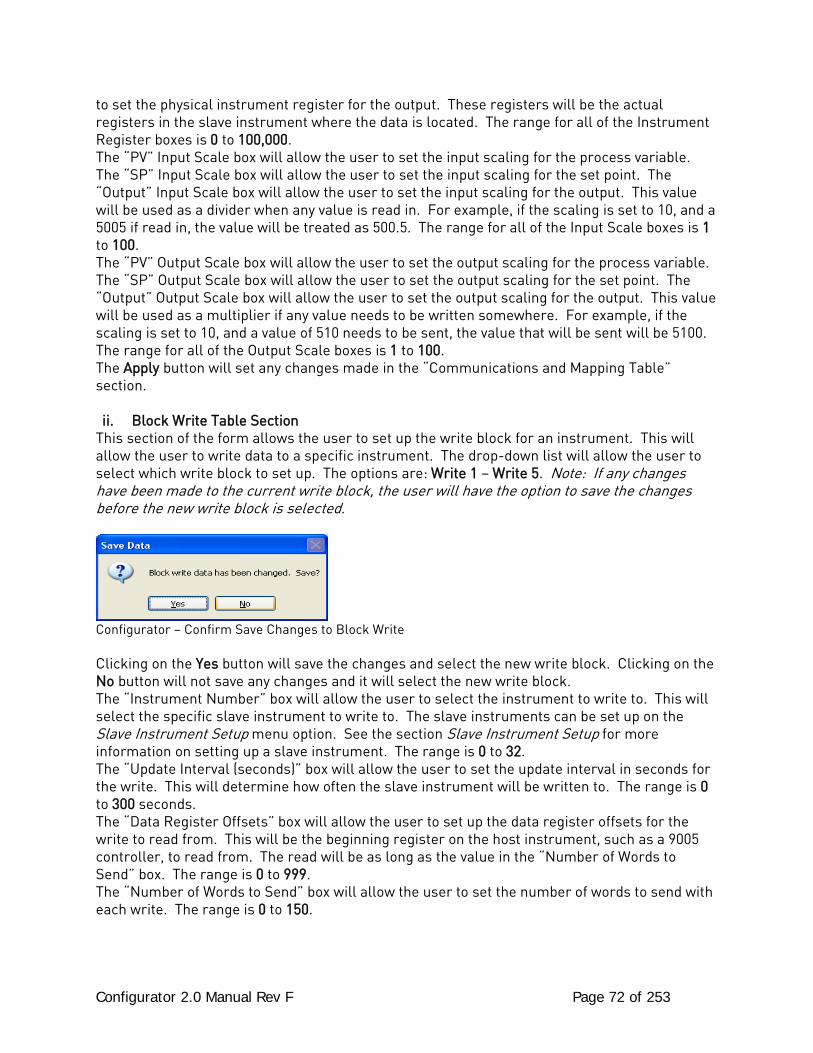
Configurator 2.0 Manual Rev F Page 72 of 253
to set the physical instrument register for the output. These registers will be the actual registers in the slave instrument where the data is located. The range for all of the Instrument Register boxes is 0 to 100,000. The “PV” Input Scale box will allow the user to set the input scaling for the process variable. The “SP” Input Scale box will allow the user to set the input scaling for the set point. The “Output” Input Scale box will allow the user to set the input scaling for the output. This value will be used as a divider when any value is read in. For example, if the scaling is set to 10, and a 5005 if read in, the value will be treated as 500.5. The range for all of the Input Scale boxes is 1 to 100. The “PV” Output Scale box will allow the user to set the output scaling for the process variable. The “SP” Output Scale box will allow the user to set the output scaling for the set point. The “Output” Output Scale box will allow the user to set the output scaling for the output. This value will be used as a multiplier if any value needs to be written somewhere. For example, if the scaling is set to 10, and a value of 510 needs to be sent, the value that will be sent will be 5100. The range for all of the Output Scale boxes is 1 to 100. The Apply button will set any changes made in the “Communications and Mapping Table” section. ii. Block Write Table Section
This section of the form allows the user to set up the write block for an instrument. This will allow the user to write data to a specific instrument. The drop-down list will allow the user to select which write block to set up. The options are: Write 1 – Write 5. Note: If any changes have been made to the current write block, the user will have the option to save the changes before the new write block is selected.
Configurator – Confirm Save Changes to Block Write Clicking on the Yes button will save the changes and select the new write block. Clicking on the No button will not save any changes and it will select the new write block. The “Instrument Number” box will allow the user to select the instrument to write to. This will select the specific slave instrument to write to. The slave instruments can be set up on the Slave Instrument Setup menu option. See the section Slave Instrument Setup for more information on setting up a slave instrument. The range is 0 to 32. The “Update Interval (seconds)” box will allow the user to set the update interval in seconds for the write. This will determine how often the slave instrument will be written to. The range is 0 to 300 seconds. The “Data Register Offsets” box will allow the user to set up the data register offsets for the write to read from. This will be the beginning register on the host instrument, such as a 9005 controller, to read from. The read will be as long as the value in the “Number of Words to Send” box. The range is 0 to 999. The “Number of Words to Send” box will allow the user to set the number of words to send with each write. The range is 0 to 150.
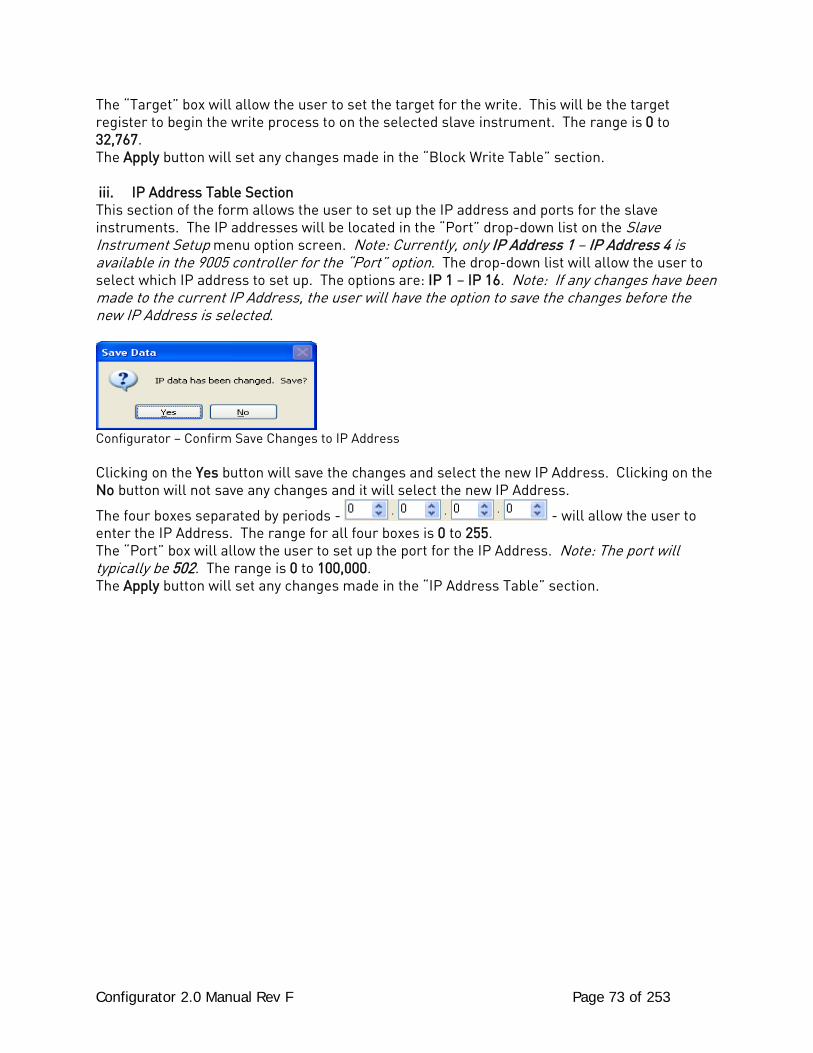
Configurator 2.0 Manual Rev F Page 73 of 253
The “Target” box will allow the user to set the target for the write. This will be the target register to begin the write process to on the selected slave instrument. The range is 0 to 32,767. The Apply button will set any changes made in the “Block Write Table” section. iii. IP Address Table Section This section of the form allows the user to set up the IP address and ports for the slave instruments. The IP addresses will be located in the “Port” drop-down list on the Slave Instrument Setup menu option screen. Note: Currently, only IP Address 1 – IP Address 4 is available in the 9005 controller for the “Port” option. The drop-down list will allow the user to select which IP address to set up. The options are: IP 1 – IP 16. Note: If any changes have been made to the current IP Address, the user will have the option to save the changes before the new IP Address is selected.
Configurator – Confirm Save Changes to IP Address Clicking on the Yes button will save the changes and select the new IP Address. Clicking on the No button will not save any changes and it will select the new IP Address.
The four boxes separated by periods - - will allow the user to enter the IP Address. The range for all four boxes is 0 to 255. The “Port” box will allow the user to set up the port for the IP Address. Note: The port will typically be 502. The range is 0 to 100,000. The Apply button will set any changes made in the “IP Address Table” section.
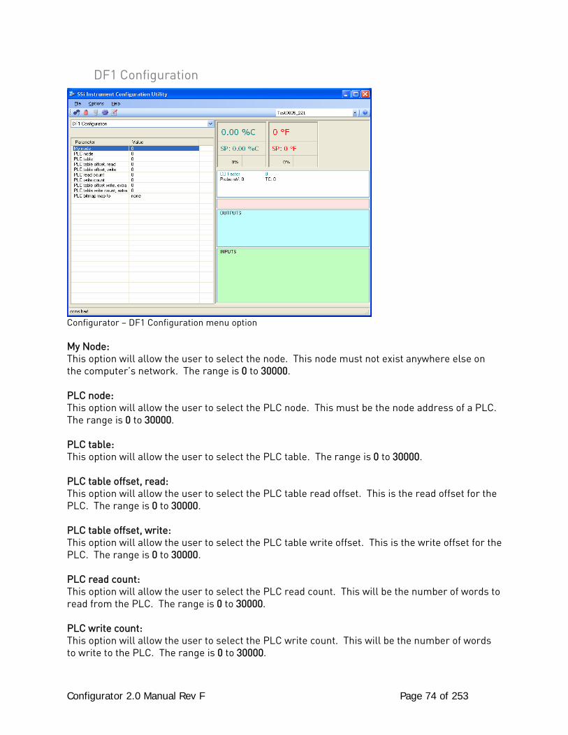
Configurator 2.0 Manual Rev F Page 74 of 253
DF1 Configuration
Configurator – DF1 Configuration menu option My Node: This option will allow the user to select the node. This node must not exist anywhere else on the computer’s network. The range is 0 to 30000. PLC node: This option will allow the user to select the PLC node. This must be the node address of a PLC. The range is 0 to 30000. PLC table: This option will allow the user to select the PLC table. The range is 0 to 30000. PLC table offset, read: This option will allow the user to select the PLC table read offset. This is the read offset for the PLC. The range is 0 to 30000. PLC table offset, write: This option will allow the user to select the PLC table write offset. This is the write offset for the PLC. The range is 0 to 30000. PLC read count: This option will allow the user to select the PLC read count. This will be the number of words to read from the PLC. The range is 0 to 30000. PLC write count: This option will allow the user to select the PLC write count. This will be the number of words to write to the PLC. The range is 0 to 30000.
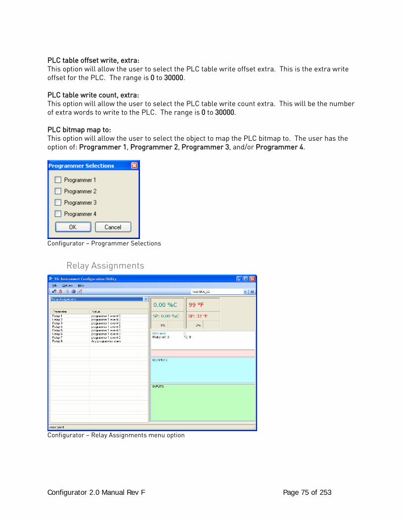
Configurator 2.0 Manual Rev F Page 75 of 253
PLC table offset write, extra: This option will allow the user to select the PLC table write offset extra. This is the extra write offset for the PLC. The range is 0 to 30000. PLC table write count, extra: This option will allow the user to select the PLC table write count extra. This will be the number of extra words to write to the PLC. The range is 0 to 30000. PLC bitmap map to: This option will allow the user to select the object to map the PLC bitmap to. The user has the option of: Programmer 1, Programmer 2, Programmer 3, and/or Programmer 4.
Configurator – Programmer Selections
Relay Assignments
Configurator – Relay Assignments menu option
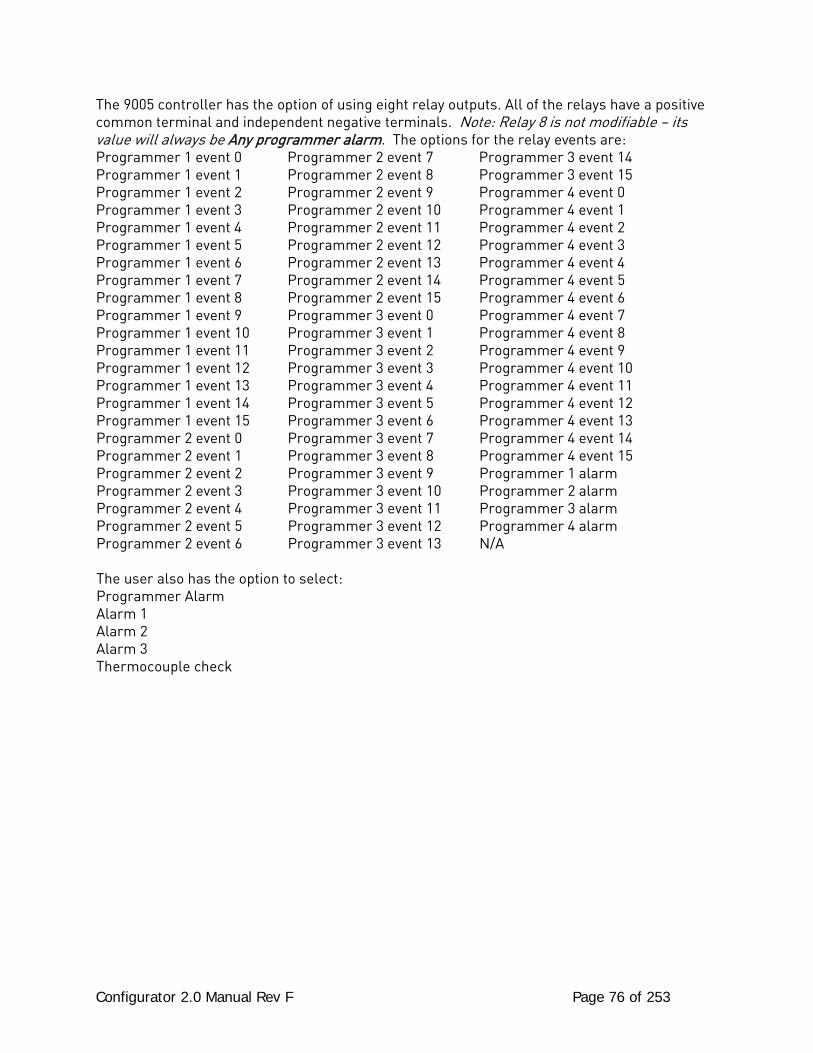
Configurator 2.0 Manual Rev F Page 76 of 253
The 9005 controller has the option of using eight relay outputs. All of the relays have a positive common terminal and independent negative terminals. Note: Relay 8 is not modifiable – its value will always be Any programmer alarm. The options for the relay events are: Programmer 1 event 0 Programmer 2 event 7 Programmer 3 event 14 Programmer 1 event 1 Programmer 2 event 8 Programmer 3 event 15 Programmer 1 event 2 Programmer 2 event 9 Programmer 4 event 0 Programmer 1 event 3 Programmer 2 event 10 Programmer 4 event 1 Programmer 1 event 4 Programmer 2 event 11 Programmer 4 event 2 Programmer 1 event 5 Programmer 2 event 12 Programmer 4 event 3 Programmer 1 event 6 Programmer 2 event 13 Programmer 4 event 4 Programmer 1 event 7 Programmer 2 event 14 Programmer 4 event 5 Programmer 1 event 8 Programmer 2 event 15 Programmer 4 event 6 Programmer 1 event 9 Programmer 3 event 0 Programmer 4 event 7 Programmer 1 event 10 Programmer 3 event 1 Programmer 4 event 8 Programmer 1 event 11 Programmer 3 event 2 Programmer 4 event 9 Programmer 1 event 12 Programmer 3 event 3 Programmer 4 event 10 Programmer 1 event 13 Programmer 3 event 4 Programmer 4 event 11 Programmer 1 event 14 Programmer 3 event 5 Programmer 4 event 12 Programmer 1 event 15 Programmer 3 event 6 Programmer 4 event 13 Programmer 2 event 0 Programmer 3 event 7 Programmer 4 event 14 Programmer 2 event 1 Programmer 3 event 8 Programmer 4 event 15 Programmer 2 event 2 Programmer 3 event 9 Programmer 1 alarm Programmer 2 event 3 Programmer 3 event 10 Programmer 2 alarm Programmer 2 event 4 Programmer 3 event 11 Programmer 3 alarm Programmer 2 event 5 Programmer 3 event 12 Programmer 4 alarm Programmer 2 event 6 Programmer 3 event 13 N/A The user also has the option to select: Programmer Alarm Alarm 1 Alarm 2 Alarm 3 Thermocouple check
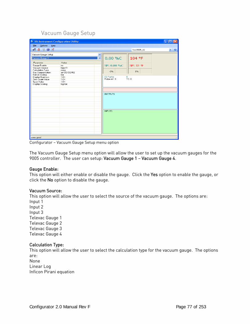
Configurator 2.0 Manual Rev F Page 77 of 253
Vacuum Gauge Setup
Configurator – Vacuum Gauge Setup menu option The Vacuum Gauge Setup menu option will allow the user to set up the vacuum gauges for the 9005 controller. The user can setup: Vacuum Gauge 1 – Vacuum Gauge 4. Gauge Enable: This option will either enable or disable the gauge. Click the Yes option to enable the gauge, or click the No option to disable the gauge. Vacuum Source: This option will allow the user to select the source of the vacuum gauge. The options are: Input 1 Input 2 Input 3 Televac Gauge 1 Televac Gauge 2 Televac Gauge 3 Televac Gauge 4 Calculation Type: This option will allow the user to select the calculation type for the vacuum gauge. The options are: None Linear Log Inficon Pirani equation
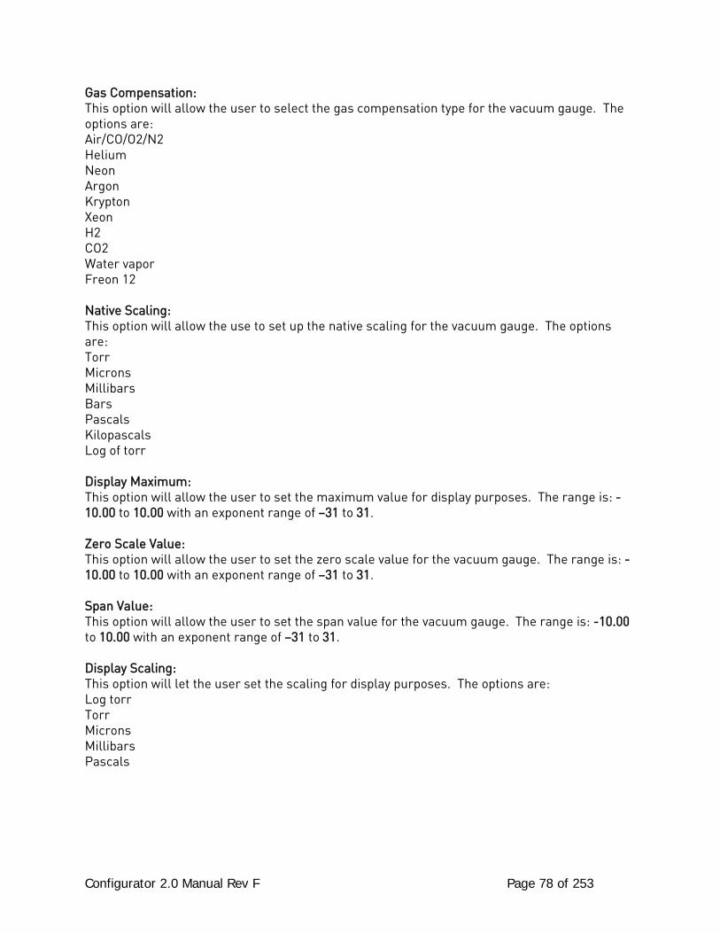
Configurator 2.0 Manual Rev F Page 78 of 253
Gas Compensation: This option will allow the user to select the gas compensation type for the vacuum gauge. The options are: Air/CO/O2/N2 Helium Neon Argon Krypton Xeon H2 CO2 Water vapor Freon 12 Native Scaling: This option will allow the use to set up the native scaling for the vacuum gauge. The options are: Torr Microns Millibars Bars Pascals Kilopascals Log of torr Display Maximum: This option will allow the user to set the maximum value for display purposes. The range is: -10.00 to 10.00 with an exponent range of –31 to 31. Zero Scale Value: This option will allow the user to set the zero scale value for the vacuum gauge. The range is: -10.00 to 10.00 with an exponent range of –31 to 31. Span Value: This option will allow the user to set the span value for the vacuum gauge. The range is: -10.00 to 10.00 with an exponent range of –31 to 31. Display Scaling: This option will let the user set the scaling for display purposes. The options are: Log torr Torr Microns Millibars Pascals
Configurator 2.0 Manual Rev F Page 79 of 253
Relay Setpoints
Configurator – Relay Setpoints Menu Option The Relay Setpoints menu option will allow the user to set the setpoints that will turn each relay on or off. The options for the setpoints are: ON SP for IN1 A ON SP for IN2 A ON SP for IN3 A OFF SP for IN1 A OFF SP for IN2 A OFF SP for IN3 A ON SP for IN1 B ON SP for IN2 B ON SP for IN3 B OFF SP for IN1 B OFF SP for IN2 B OFF SP for IN3 B ON SP for IN1 C ON SP for IN2 C ON SP for IN3 C OFF SP for IN1 C OFF SP for IN2 C OFF SP for IN3 C The range for each setpoint is: -10.00 to 10.00 with an exponent range of –31 to 31.
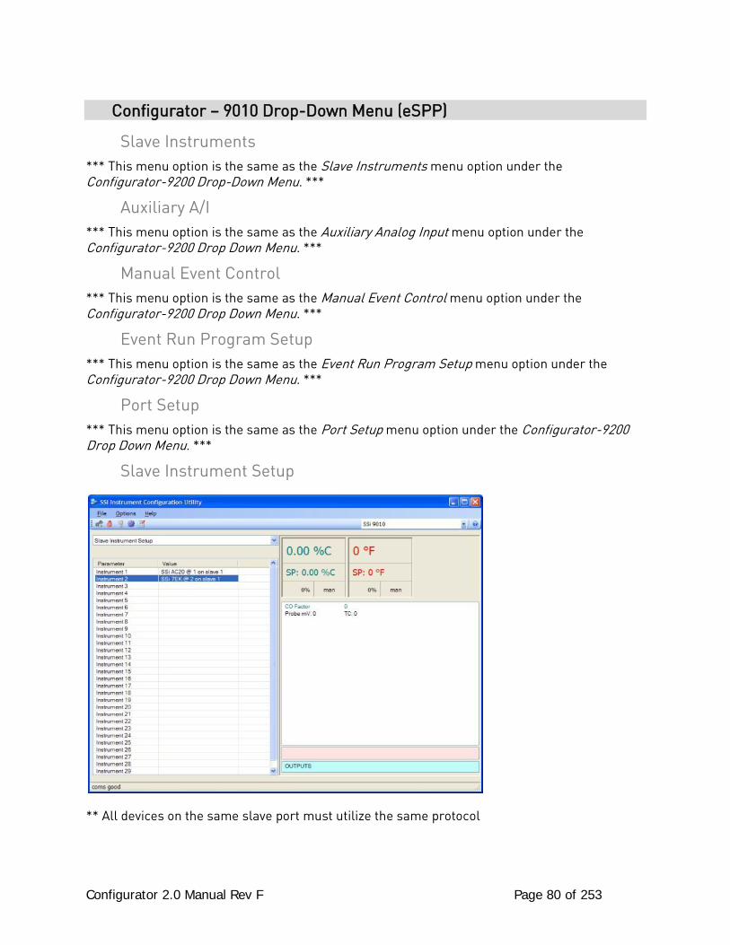
Configurator 2.0 Manual Rev F Page 80 of 253
Configurator – 9010 Drop-Down Menu (eSPP)
Slave Instruments *** This menu option is the same as the Slave Instruments menu option under the Configurator-9200 Drop-Down Menu. ***
Auxiliary A/I *** This menu option is the same as the Auxiliary Analog Input menu option under the Configurator-9200 Drop Down Menu. ***
Manual Event Control *** This menu option is the same as the Manual Event Control menu option under the Configurator-9200 Drop Down Menu. ***
Event Run Program Setup *** This menu option is the same as the Event Run Program Setup menu option under the Configurator-9200 Drop Down Menu. ***
Port Setup *** This menu option is the same as the Port Setup menu option under the Configurator-9200 Drop Down Menu. ***
Slave Instrument Setup
** All devices on the same slave port must utilize the same protocol
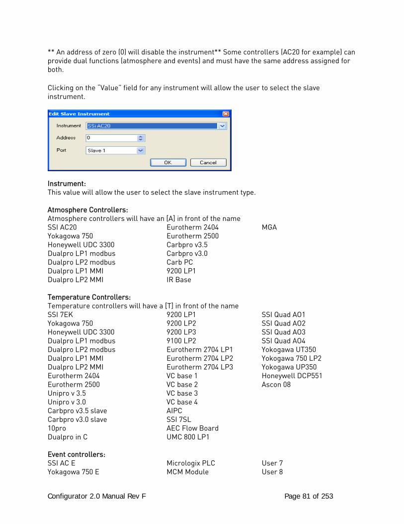
Configurator 2.0 Manual Rev F Page 81 of 253
** An address of zero (0) will disable the instrument** Some controllers (AC20 for example) can provide dual functions (atmosphere and events) and must have the same address assigned for both. Clicking on the “Value” field for any instrument will allow the user to select the slave instrument.
Instrument: This value will allow the user to select the slave instrument type. Atmosphere Controllers: Atmosphere controllers will have an [A] in front of the name SSI AC20 Eurotherm 2404 MGA Yokagowa 750 Eurotherm 2500 Honeywell UDC 3300 Carbpro v3.5 Dualpro LP1 modbus Carbpro v3.0 Dualpro LP2 modbus Carb PC Dualpro LP1 MMI 9200 LP1 Dualpro LP2 MMI IR Base Temperature Controllers: Temperature controllers will have a [T] in front of the name SSI 7EK 9200 LP1 SSI Quad AO1 Yokagowa 750 9200 LP2 SSI Quad AO2 Honeywell UDC 3300 9200 LP3 SSI Quad AO3 Dualpro LP1 modbus 9100 LP2 SSI Quad AO4 Dualpro LP2 modbus Eurotherm 2704 LP1 Yokogawa UT350 Dualpro LP1 MMI Eurotherm 2704 LP2 Yokogawa 750 LP2 Dualpro LP2 MMI Eurotherm 2704 LP3 Yokogawa UP350 Eurotherm 2404 VC base 1 Honeywell DCP551 Eurotherm 2500 VC base 2 Ascon 08 Unipro v 3.5 VC base 3 Unipro v 3.0 VC base 4 Carbpro v3.5 slave AIPC Carbpro v3.0 slave SSI 7SL 10pro AEC Flow Board Dualpro in C UMC 800 LP1 Event controllers: SSI AC E Micrologix PLC User 7 Yokagowa 750 E MCM Module User 8
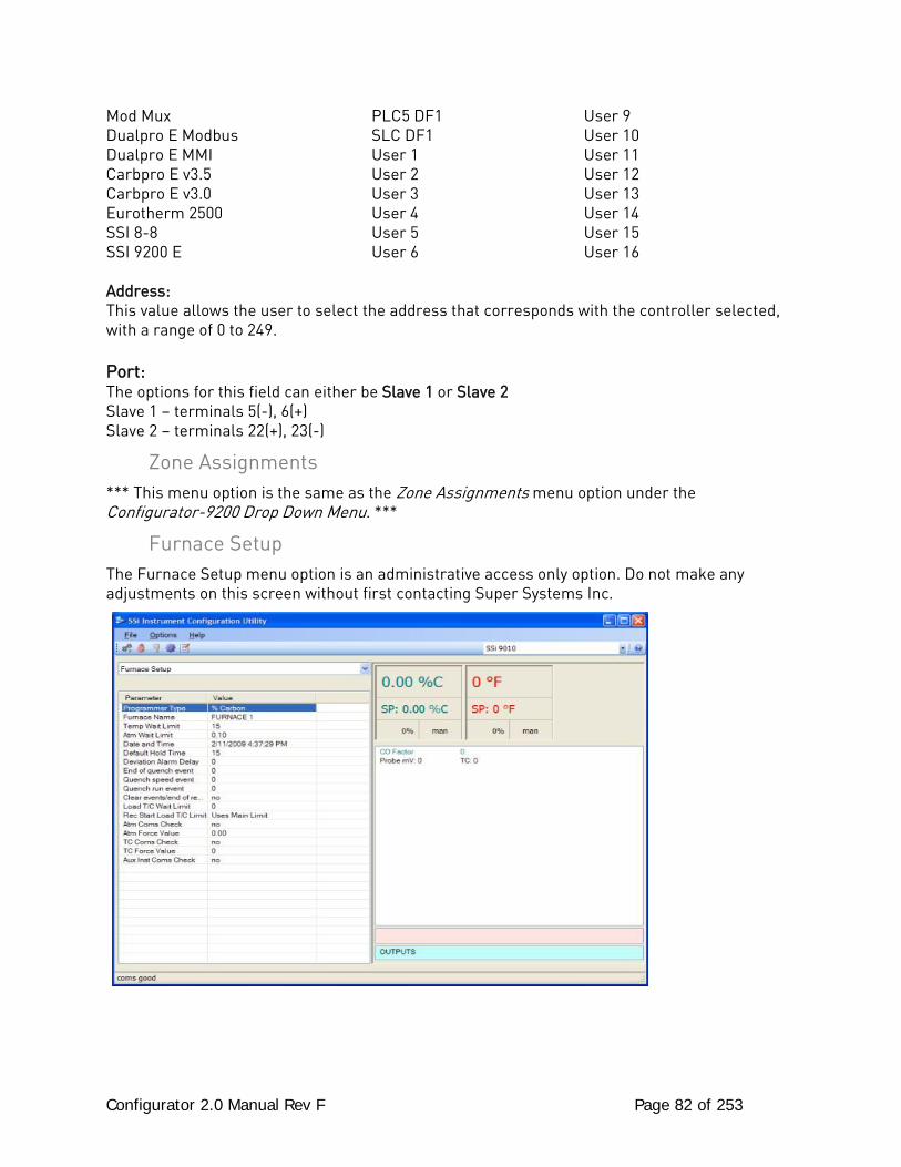
Configurator 2.0 Manual Rev F Page 82 of 253
Mod Mux PLC5 DF1 User 9 Dualpro E Modbus SLC DF1 User 10 Dualpro E MMI User 1 User 11 Carbpro E v3.5 User 2 User 12 Carbpro E v3.0 User 3 User 13 Eurotherm 2500 User 4 User 14 SSI 8-8 User 5 User 15 SSI 9200 E User 6 User 16 Address: This value allows the user to select the address that corresponds with the controller selected, with a range of 0 to 249. Port: The options for this field can either be Slave 1 or Slave 2 Slave 1 – terminals 5(-), 6(+) Slave 2 – terminals 22(+), 23(-)
Zone Assignments *** This menu option is the same as the Zone Assignments menu option under the Configurator-9200 Drop Down Menu. ***
Furnace Setup The Furnace Setup menu option is an administrative access only option. Do not make any adjustments on this screen without first contacting Super Systems Inc.
Configurator 2.0 Manual Rev F Page 83 of 253
PVT Type: The PVT type is the mode the device runs in (Carbon, Dewpoint, etc.). The mode selected determines the calculations and scaling for the Process Variable. Any time this selection is changed it is necessary to reset the factory defaults to ensure all parameters have been changed to the new Process Variable. Clicking on this value will display an input box with a drop-down list from which the user can select a new PVT Type. The values for the PVT type are: % Carbon, Dew Point, Oxygen, Millivolts, or Multi-loop. Furnace Name: This value will define the name of the furnace. Clicking on the “Value” column will bring up an input box where the user can enter the furnace’s name. Temp Wait Limit: This value will define the temperature wait limit. The range is 0 to 4000. Atm Wait Limit: This value will define the atmosphere wait limit. The range is 0.00 to 40.00. Date and Time: This value is the current date and time on the 9010 controller only (not the local computer or the touch screen, if applicable). Clicking on the “Value” column will allow the user to set a new date and time on the controller. Note: The date and time of the touch screen can be changed (if necessary) by selecting the date and time in the lower right corner on the touch screen under the menu. This can be reached by going through the menu, and shutting down the software. Then, at the CE screen the date and time can be changed by double taping the time in the bottom right corner and setting it, then select “apply”. For this to take effect the screen needs to be rebooted; on the older TPC 642 displays, the registry needs to be saved under TPC Configuration icon, the Misc Tab and then reboot the touch screen. The date and time that is recorded on the flash card (and therefore the datalog data) is the date and time of the Advantech display not the controller. Default Hold Time: This value is the default holding time for the furnace. The range is 0 to 10000. Deviation Alarm delay: This value is the delay for the deviation alarm. The range is 0 to 10000. End of Quench Event: Tells the programmer which event to signal end of quench (related to which relay it is assigned). The list of possible values is: 0 – 14. Quench Speed Event: Tells the programmer which event will signal the quench speed. The list of possible values is: 0 – 14. Quench Run Event: Tells the programmer which event will signal quench run. The list of possible values is: 0 – 14. Clear events/end of recipe:
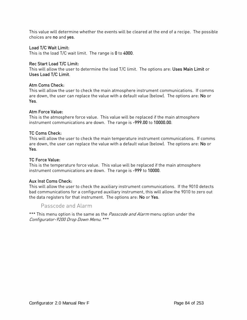
Configurator 2.0 Manual Rev F Page 84 of 253
This value will determine whether the events will be cleared at the end of a recipe. The possible choices are no and yes. Load T/C Wait Limit: This is the load T/C wait limit. The range is 0 to 4000. Rec Start Load T/C Limit: This will allow the user to determine the load T/C limit. The options are: Uses Main Limit or Uses Load T/C Limit. Atm Coms Check: This will allow the user to check the main atmosphere instrument communications. If comms are down, the user can replace the value with a default value (below). The options are: No or Yes. Atm Force Value: This is the atmosphere force value. This value will be replaced if the main atmosphere instrument communications are down. The range is -999.00 to 10000.00. TC Coms Check: This will allow the user to check the main temperature instrument communications. If comms are down, the user can replace the value with a default value (below). The options are: No or Yes. TC Force Value: This is the temperature force value. This value will be replaced if the main atmosphere instrument communications are down. The range is -999 to 10000. Aux Inst Coms Check: This will allow the user to check the auxiliary instrument communications. If the 9010 detects bad communications for a configured auxiliary instrument, this will allow the 9010 to zero out the data registers for that instrument. The options are: No or Yes.
Passcode and Alarm *** This menu option is the same as the Passcode and Alarm menu option under the Configurator-9200 Drop Down Menu. ***
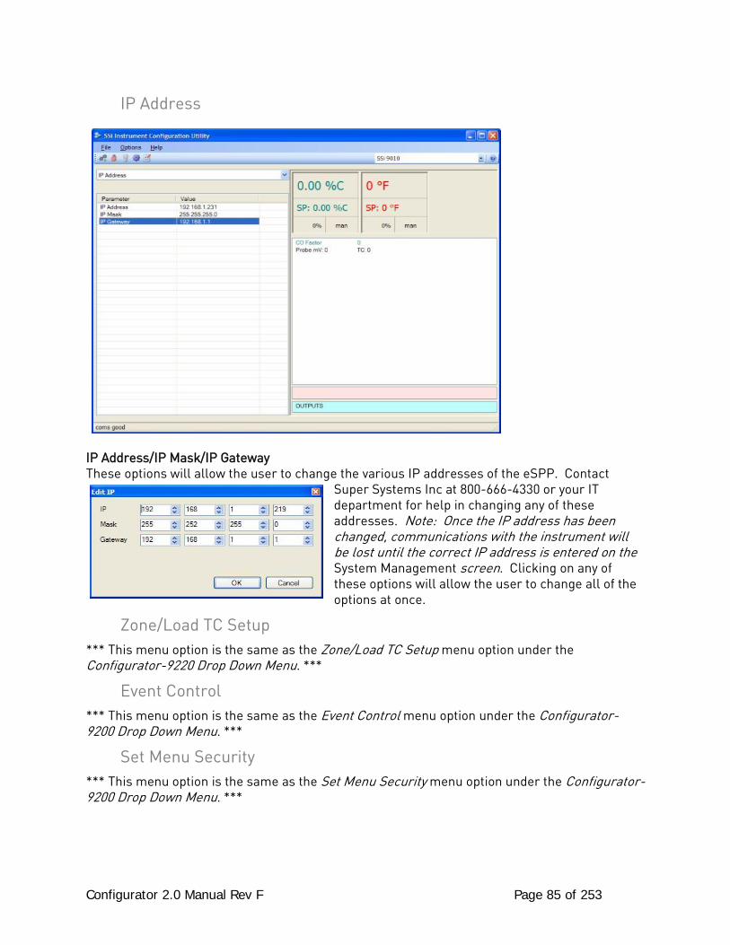
Configurator 2.0 Manual Rev F Page 85 of 253
IP Address
IP Address/IP Mask/IP Gateway These options will allow the user to change the various IP addresses of the eSPP. Contact
Super Systems Inc at 800-666-4330 or your IT department for help in changing any of these addresses. Note: Once the IP address has been changed, communications with the instrument will be lost until the correct IP address is entered on the System Management screen. Clicking on any of these options will allow the user to change all of the options at once.
Zone/Load TC Setup *** This menu option is the same as the Zone/Load TC Setup menu option under the Configurator-9220 Drop Down Menu. ***
Event Control *** This menu option is the same as the Event Control menu option under the Configurator-9200 Drop Down Menu. ***
Set Menu Security *** This menu option is the same as the Set Menu Security menu option under the Configurator-9200 Drop Down Menu. ***
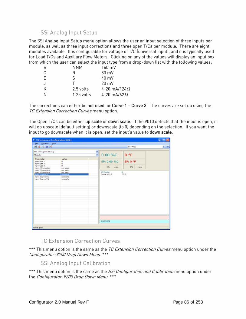
Configurator 2.0 Manual Rev F Page 86 of 253
SSi Analog Input Setup The SSi Analog Input Setup menu option allows the user an input selection of three inputs per module, as well as three input corrections and three open T/Cs per module. There are eight modules available. It is configurable for voltage of T/C (universal input), and it is typically used for Load T/Cs and Auxiliary Flow Meters. Clicking on any of the values will display an input box from which the user can select the input type from a drop-down list with the following values: B NNM 160 mV C R 80 mV E S 40 mV J T 20 mV K 2.5 volts 4-20 mA/124Ω N 1.25 volts 4-20 mA/62Ω The corrections can either be not used, or Curve 1 – Curve 3. The curves are set up using the TC Extension Correction Curves menu option. The Open T/Cs can be either up scale or down scale. If the 9010 detects that the input is open, it will go upscale (default setting) or downscale (to 0) depending on the selection. If you want the input to go downscale when it is open, set the input's value to down scale.
TC Extension Correction Curves *** This menu option is the same as the TC Extension Correction Curves menu option under the Configurator-9200 Drop Down Menu. ***
SSi Analog Input Calibration *** This menu option is the same as the SSi Configuration and Calibration menu option under the Configurator-9200 Drop Down Menu. ***

Configurator 2.0 Manual Rev F Page 87 of 253
Generic Mapping Setups *** This menu option is the same as the Generic Mapping Setups menu option under the Configurator-9200 Drop Down Menu. ***
ADAM Module Offset Correction *** This menu option is the same as the ADAM Module Offset Correction menu option under the Configurator-9200 Drop Down Menu. ***
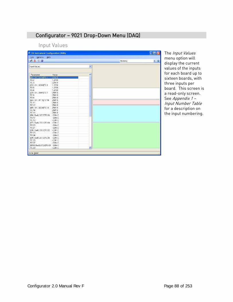
Configurator 2.0 Manual Rev F Page 88 of 253
Configurator – 9021 Drop-Down Menu (DAQ)
Input Values The Input Values menu option will display the current values of the inputs for each board up to sixteen boards, with three inputs per board. This screen is a read-only screen. See Appendix 1 – Input Number Table for a description on the input numbering.
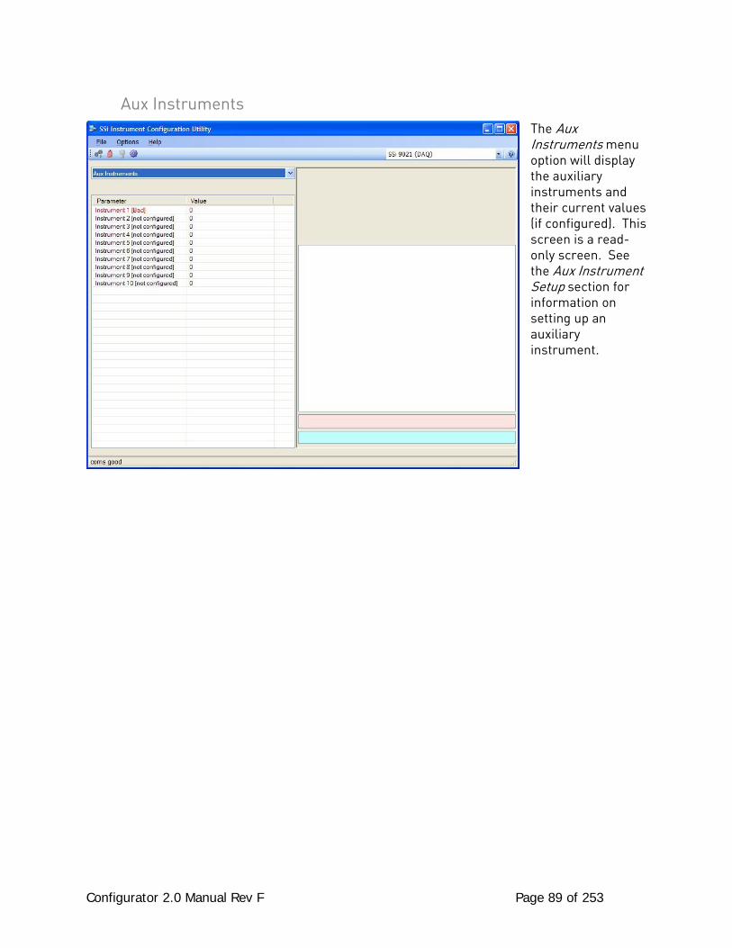
Configurator 2.0 Manual Rev F Page 89 of 253
Aux Instruments The Aux Instruments menu option will display the auxiliary instruments and their current values (if configured). This screen is a read-only screen. See the Aux Instrument Setup section for information on setting up an auxiliary instrument.
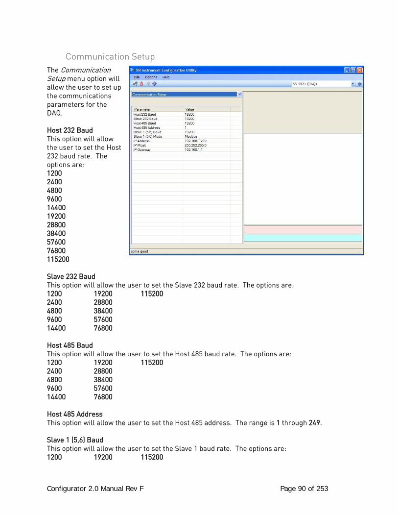
Configurator 2.0 Manual Rev F Page 90 of 253
Communication Setup The Communication Setup menu option will allow the user to set up the communications parameters for the DAQ. Host 232 Baud This option will allow the user to set the Host 232 baud rate. The options are: 1200 2400 4800 9600 14400 19200 28800 38400 57600 76800 115200 Slave 232 Baud This option will allow the user to set the Slave 232 baud rate. The options are: 1200 19200 115200 2400 28800 4800 38400 9600 57600 14400 76800 Host 485 Baud This option will allow the user to set the Host 485 baud rate. The options are: 1200 19200 115200 2400 28800 4800 38400 9600 57600 14400 76800 Host 485 Address This option will allow the user to set the Host 485 address. The range is 1 through 249. Slave 1 (5,6) Baud This option will allow the user to set the Slave 1 baud rate. The options are: 1200 19200 115200
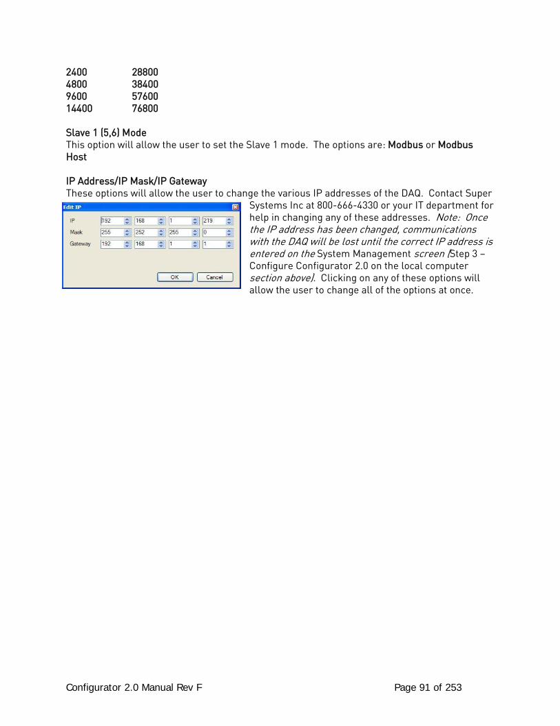
Configurator 2.0 Manual Rev F Page 91 of 253
2400 28800 4800 38400 9600 57600 14400 76800 Slave 1 (5,6) Mode This option will allow the user to set the Slave 1 mode. The options are: Modbus or Modbus Host IP Address/IP Mask/IP Gateway These options will allow the user to change the various IP addresses of the DAQ. Contact Super
Systems Inc at 800-666-4330 or your IT department for help in changing any of these addresses. Note: Once the IP address has been changed, communications with the DAQ will be lost until the correct IP address is entered on the System Management screen (Step 3 – Configure Configurator 2.0 on the local computer section above). Clicking on any of these options will allow the user to change all of the options at once.
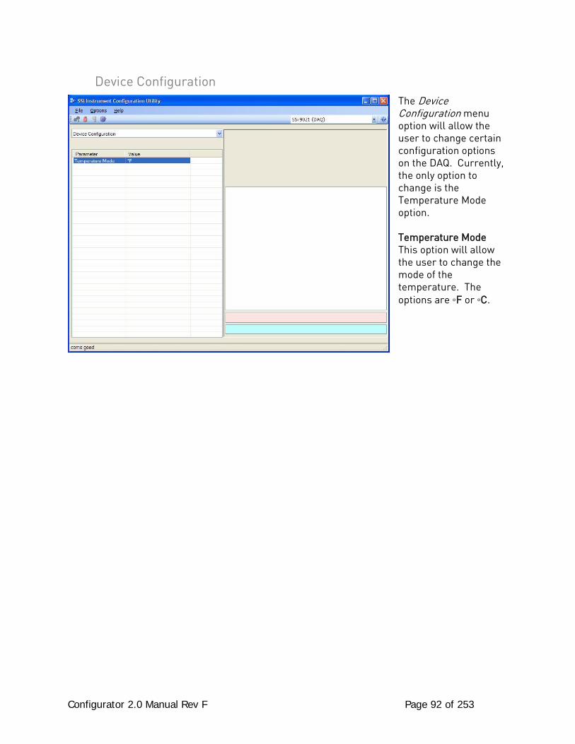
Configurator 2.0 Manual Rev F Page 92 of 253
Device Configuration The Device Configuration menu option will allow the user to change certain configuration options on the DAQ. Currently, the only option to change is the Temperature Mode option. Temperature Mode This option will allow the user to change the mode of the temperature. The options are ◦F or ◦C.
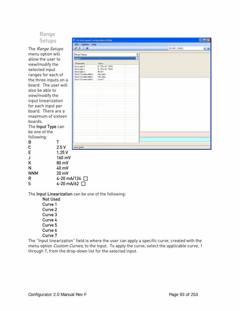
Configurator 2.0 Manual Rev F Page 93 of 253
Range Setups
The Range Setups menu option will allow the user to view/modify the selected input ranges for each of the three inputs on a board. The user will also be able to view/modify the input linearization for each input per board. There are a maximum of sixteen boards. The Input Type can be one of the following: B T C 2.5 V E 1.25 V J 160 mV K 80 mV N 40 mV NNM 20 mV R 4-20 mA/124 S 4-20 mA/62 The Input Linearization can be one of the following: Not Used Curve 1 Curve 2 Curve 3 Curve 4 Curve 5 Curve 6 Curve 7 The “Input linearization” field is where the user can apply a specific curve, created with the menu option Custom Curves, to the input. To apply the curve, select the applicable curve, 1 through 7, from the drop-down list for the selected input.
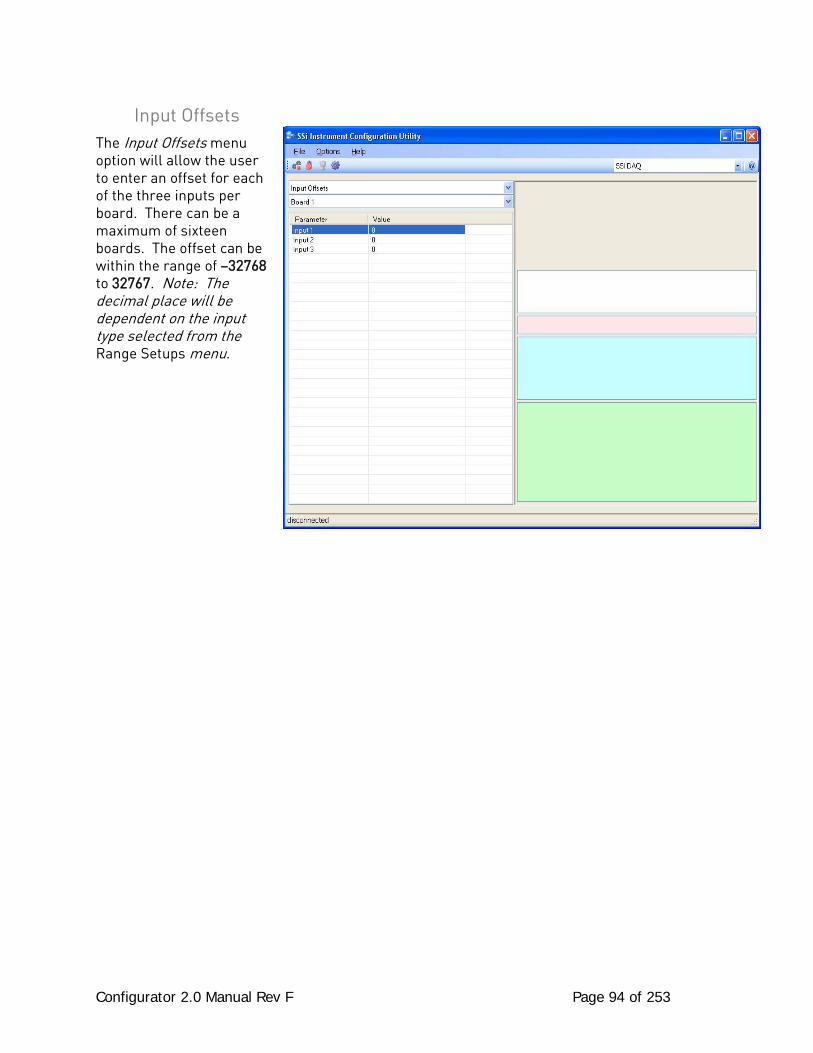
Configurator 2.0 Manual Rev F Page 94 of 253
Input Offsets The Input Offsets menu option will allow the user to enter an offset for each of the three inputs per board. There can be a maximum of sixteen boards. The offset can be within the range of –32768 to 32767. Note: The decimal place will be dependent on the input type selected from the Range Setups menu.
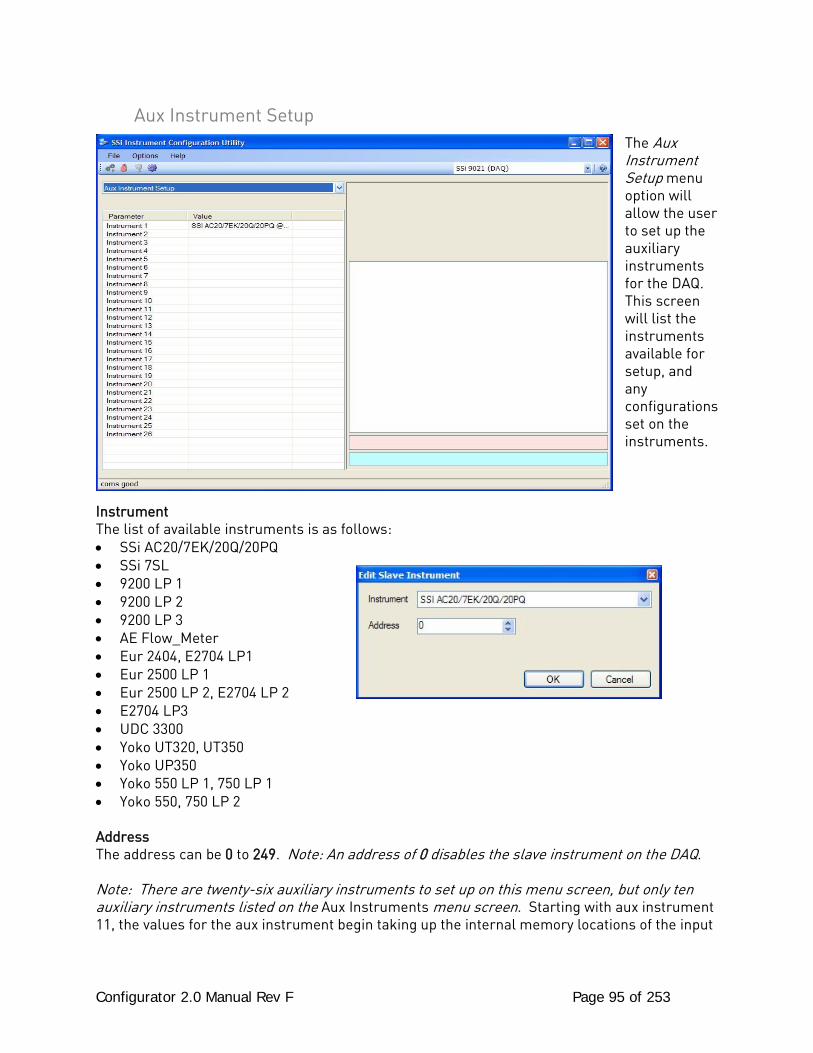
Configurator 2.0 Manual Rev F Page 95 of 253
Aux Instrument Setup The Aux Instrument Setup menu option will allow the user to set up the auxiliary instruments for the DAQ. This screen will list the instruments available for setup, and any configurations set on the instruments.
Instrument The list of available instruments is as follows: • SSi AC20/7EK/20Q/20PQ • SSi 7SL • 9200 LP 1 • 9200 LP 2 • 9200 LP 3 • AE Flow_Meter • Eur 2404, E2704 LP1 • Eur 2500 LP 1 • Eur 2500 LP 2, E2704 LP 2 • E2704 LP3 • UDC 3300 • Yoko UT320, UT350 • Yoko UP350 • Yoko 550 LP 1, 750 LP 1 • Yoko 550, 750 LP 2 Address The address can be 0 to 249. Note: An address of 0 disables the slave instrument on the DAQ. Note: There are twenty-six auxiliary instruments to set up on this menu screen, but only ten auxiliary instruments listed on the Aux Instruments menu screen. Starting with aux instrument 11, the values for the aux instrument begin taking up the internal memory locations of the input

Configurator 2.0 Manual Rev F Page 96 of 253
boards, starting with board 16: Aux instrument 11 replaces board 16; aux instrument 12 replaces board 15, etc.
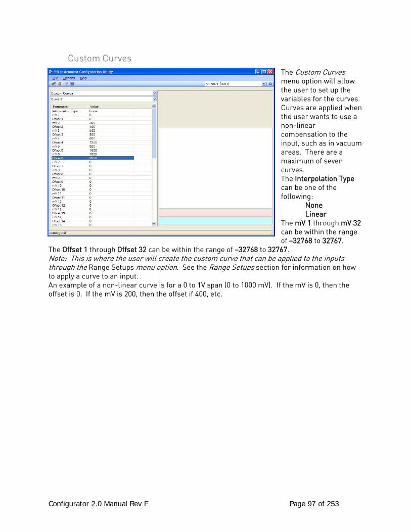
Configurator 2.0 Manual Rev F Page 97 of 253
Custom Curves The Custom Curves menu option will allow the user to set up the variables for the curves. Curves are applied when the user wants to use a non-linear compensation to the input, such as in vacuum areas. There are a maximum of seven curves. The Interpolation Type can be one of the following: None Linear The mV 1 through mV 32 can be within the range of –32768 to 32767.
The Offset 1 through Offset 32 can be within the range of –32768 to 32767. Note: This is where the user will create the custom curve that can be applied to the inputs through the Range Setups menu option. See the Range Setups section for information on how to apply a curve to an input. An example of a non-linear curve is for a 0 to 1V span (0 to 1000 mV). If the mV is 0, then the offset is 0. If the mV is 200, then the offset if 400, etc.
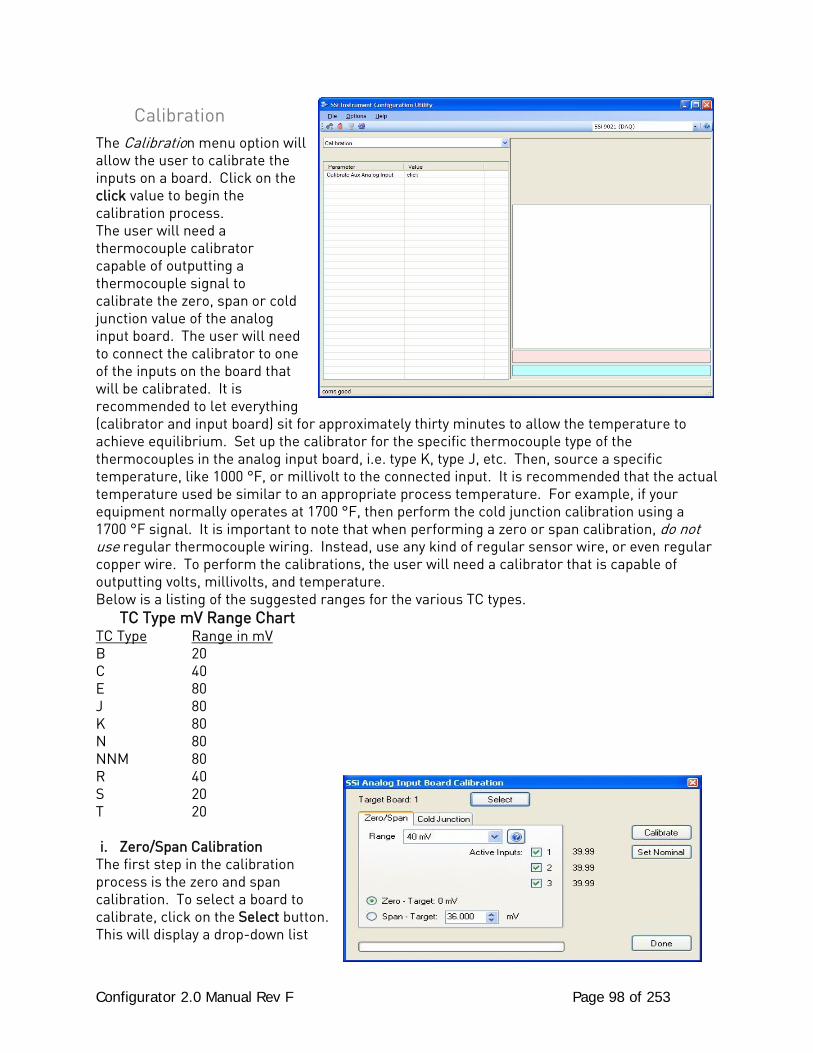
Configurator 2.0 Manual Rev F Page 98 of 253
Calibration The Calibration menu option will allow the user to calibrate the inputs on a board. Click on the click value to begin the calibration process. The user will need a thermocouple calibrator capable of outputting a thermocouple signal to calibrate the zero, span or cold junction value of the analog input board. The user will need to connect the calibrator to one of the inputs on the board that will be calibrated. It is recommended to let everything (calibrator and input board) sit for approximately thirty minutes to allow the temperature to achieve equilibrium. Set up the calibrator for the specific thermocouple type of the thermocouples in the analog input board, i.e. type K, type J, etc. Then, source a specific temperature, like 1000 °F, or millivolt to the connected input. It is recommended that the actual temperature used be similar to an appropriate process temperature. For example, if your equipment normally operates at 1700 °F, then perform the cold junction calibration using a 1700 °F signal. It is important to note that when performing a zero or span calibration, do not use regular thermocouple wiring. Instead, use any kind of regular sensor wire, or even regular copper wire. To perform the calibrations, the user will need a calibrator that is capable of outputting volts, millivolts, and temperature. Below is a listing of the suggested ranges for the various TC types. TC Type mV Range Chart TC Type Range in mV B 20 C 40 E 80 J 80 K 80 N 80 NNM 80 R 40 S 20 T 20 i. Zero/Span Calibration
The first step in the calibration process is the zero and span calibration. To select a board to calibrate, click on the Select button. This will display a drop-down list
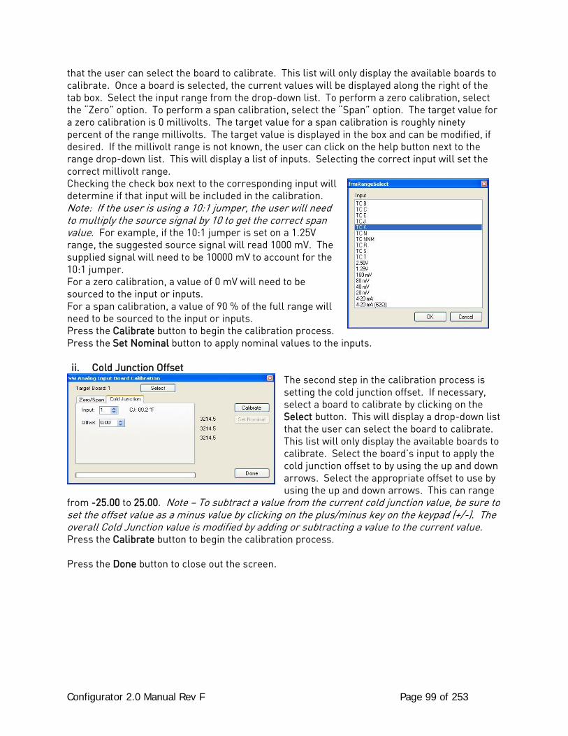
Configurator 2.0 Manual Rev F Page 99 of 253
that the user can select the board to calibrate. This list will only display the available boards to calibrate. Once a board is selected, the current values will be displayed along the right of the tab box. Select the input range from the drop-down list. To perform a zero calibration, select the “Zero” option. To perform a span calibration, select the “Span” option. The target value for a zero calibration is 0 millivolts. The target value for a span calibration is roughly ninety percent of the range millivolts. The target value is displayed in the box and can be modified, if desired. If the millivolt range is not known, the user can click on the help button next to the range drop-down list. This will display a list of inputs. Selecting the correct input will set the correct millivolt range. Checking the check box next to the corresponding input will determine if that input will be included in the calibration. Note: If the user is using a 10:1 jumper, the user will need to multiply the source signal by 10 to get the correct span value. For example, if the 10:1 jumper is set on a 1.25V range, the suggested source signal will read 1000 mV. The supplied signal will need to be 10000 mV to account for the 10:1 jumper. For a zero calibration, a value of 0 mV will need to be sourced to the input or inputs. For a span calibration, a value of 90 % of the full range will need to be sourced to the input or inputs. Press the Calibrate button to begin the calibration process. Press the Set Nominal button to apply nominal values to the inputs. ii. Cold Junction Offset
The second step in the calibration process is setting the cold junction offset. If necessary, select a board to calibrate by clicking on the Select button. This will display a drop-down list that the user can select the board to calibrate. This list will only display the available boards to calibrate. Select the board’s input to apply the cold junction offset to by using the up and down arrows. Select the appropriate offset to use by using the up and down arrows. This can range
from -25.00 to 25.00. Note – To subtract a value from the current cold junction value, be sure to set the offset value as a minus value by clicking on the plus/minus key on the keypad (+/-). The overall Cold Junction value is modified by adding or subtracting a value to the current value. Press the Calibrate button to begin the calibration process. Press the Done button to close out the screen.
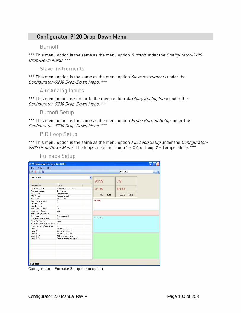
Configurator 2.0 Manual Rev F Page 100 of 253
Configurator-9120 Drop-Down Menu
Burnoff *** This menu option is the same as the menu option Burnoff under the Configurator-9200 Drop-Down Menu. ***
Slave Instruments *** This menu option is the same as the menu option Slave instruments under the Configurator-9200 Drop-Down Menu. ***
Aux Analog Inputs *** This menu option is similar to the menu option Auxiliary Analog Input under the Configurator-9200 Drop-Down Menu. ***
Burnoff Setup *** This menu option is the same as the menu option Probe Burnoff Setup under the Configurator-9200 Drop-Down Menu. ***
PID Loop Setup *** This menu option is the same as the menu option PID Loop Setup under the Configurator-9200 Drop-Down Menu. The loops are either Loop 1 – O2, or Loop 2 – Temperature. ***
Furnace Setup
Configurator – Furnace Setup menu option
Configurator 2.0 Manual Rev F Page 101 of 253
The Furnace Setup menu option is an administrative access only option. Do not make any adjustments on this screen without first contacting Super Systems Inc. Date and Time: This option will display the current date and time on the 9120 controller only (not the local computer or the touch screen, if applicable). From this menu option, the user can change the date/time on the 9120 controller. Note: The date and time of the touch screen can be changed (if necessary) by selecting the date and time in the lower right corner on the touch screen under the menu. This can be reached by going through the menu, and shutting down the software. Then, at the CE screen the date and time can be changed by double taping the time in the bottom right corner and setting it, then select “apply”. For this to take effect the screen needs to be rebooted; on the older TPC 642 displays the registry needs to be saved under TPC Configuration icon, the Misc Tab and then reboot the touch screen. The date and time that is recorded on the flash card (and therefore the datalog data) is the date and time of the Advantech display not the controller. Furnace Name: This value will define the name of the furnace. Clicking on the “Value” column will bring up an input box where the user can enter the furnace’s name. PV1 Name: This value will define the name of the first process variable. Clicking on the “Value” column will bring up an input box where the user can enter the PV’s name. PV2 Name: This value will define the name of the second process variable. Clicking on the “Value” column will bring up an input box where the user can enter the PV’s name. PVT Type: The PVT type is the mode the device runs in (Carbon, Dewpoint, etc.). The mode selected determines the calculations and scaling for the Process Variable. Any time this selection is changed it is necessary to reset the factory defaults to ensure all parameters have been changed to the new Process Variable. Clicking on this value will display an input box with a drop-down list from which the user can select a new PVT Type. The values for the PVT type are: % Carbon, Dew Point, Oxygen, Millivolt, or Redundant Probe. Temperature Mode: This value determines the specific temperature scale to be used. It can be either Degrees °F or degrees °C. Level 1 Code: Typically, operations used by a supervisor require a level 1 code for access. When a supervisor is logged in, the lock on the toolbar will be gold, . To change the level 1 passcode, click on the “Level 1 Code” value (range is –32768 to 32767) and an input box will be displayed where the user can select a new value. Level 2 Code:
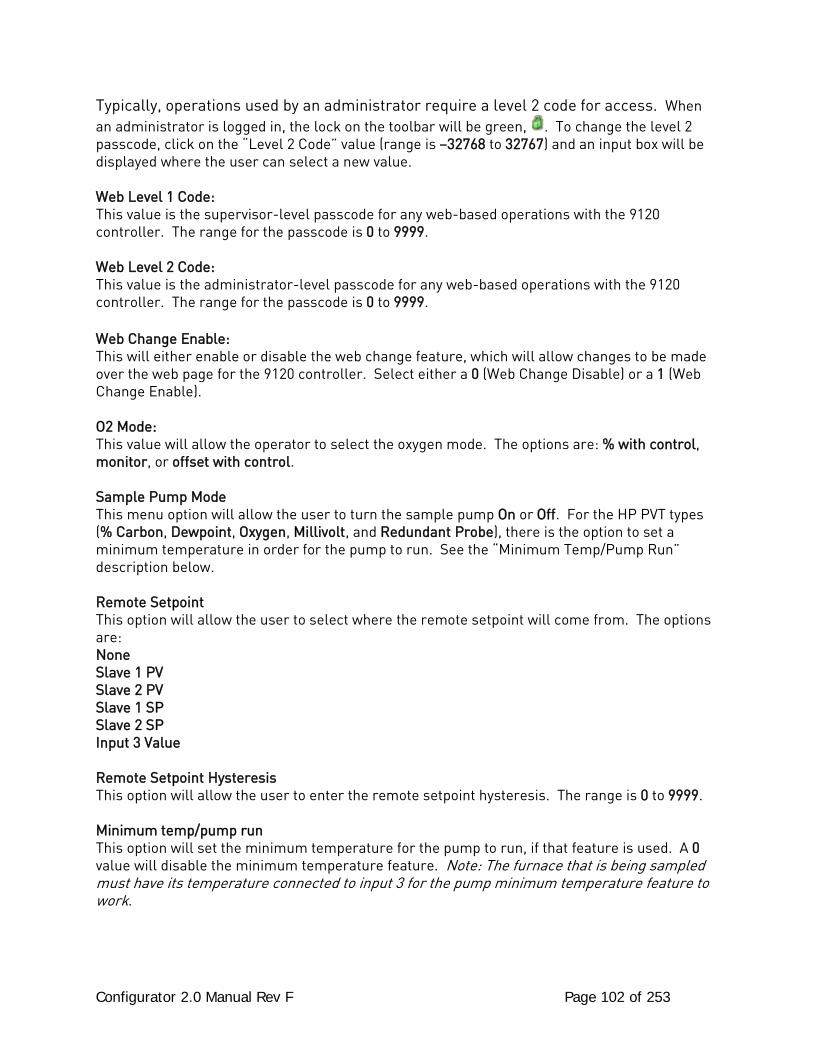
Configurator 2.0 Manual Rev F Page 102 of 253
Typically, operations used by an administrator require a level 2 code for access. When an administrator is logged in, the lock on the toolbar will be green, . To change the level 2 passcode, click on the “Level 2 Code” value (range is –32768 to 32767) and an input box will be displayed where the user can select a new value. Web Level 1 Code: This value is the supervisor-level passcode for any web-based operations with the 9120 controller. The range for the passcode is 0 to 9999. Web Level 2 Code: This value is the administrator-level passcode for any web-based operations with the 9120 controller. The range for the passcode is 0 to 9999. Web Change Enable: This will either enable or disable the web change feature, which will allow changes to be made over the web page for the 9120 controller. Select either a 0 (Web Change Disable) or a 1 (Web Change Enable). O2 Mode: This value will allow the operator to select the oxygen mode. The options are: % with control, monitor, or offset with control. Sample Pump Mode This menu option will allow the user to turn the sample pump On or Off. For the HP PVT types (% Carbon, Dewpoint, Oxygen, Millivolt, and Redundant Probe), there is the option to set a minimum temperature in order for the pump to run. See the “Minimum Temp/Pump Run” description below. Remote Setpoint This option will allow the user to select where the remote setpoint will come from. The options are: None Slave 1 PV Slave 2 PV Slave 1 SP Slave 2 SP Input 3 Value Remote Setpoint Hysteresis This option will allow the user to enter the remote setpoint hysteresis. The range is 0 to 9999. Minimum temp/pump run This option will set the minimum temperature for the pump to run, if that feature is used. A 0 value will disable the minimum temperature feature. Note: The furnace that is being sampled must have its temperature connected to input 3 for the pump minimum temperature feature to work.
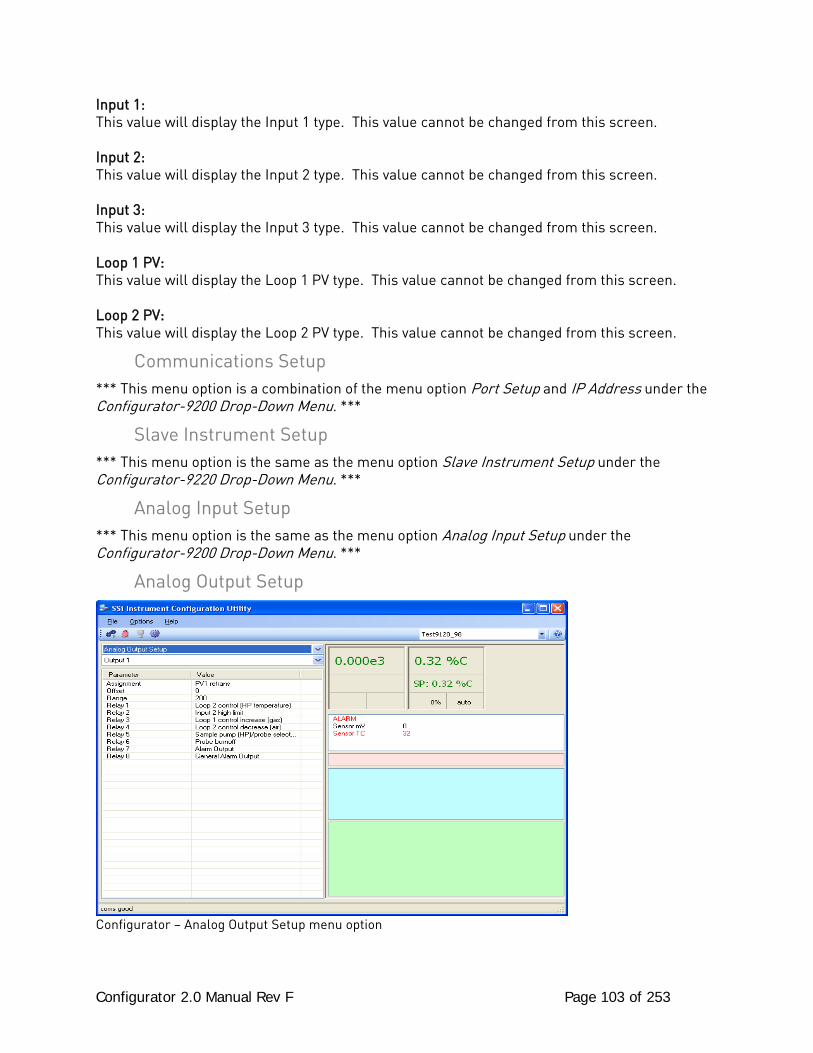
Configurator 2.0 Manual Rev F Page 103 of 253
Input 1: This value will display the Input 1 type. This value cannot be changed from this screen. Input 2: This value will display the Input 2 type. This value cannot be changed from this screen. Input 3: This value will display the Input 3 type. This value cannot be changed from this screen. Loop 1 PV: This value will display the Loop 1 PV type. This value cannot be changed from this screen. Loop 2 PV: This value will display the Loop 2 PV type. This value cannot be changed from this screen.
Communications Setup *** This menu option is a combination of the menu option Port Setup and IP Address under the Configurator-9200 Drop-Down Menu. ***
Slave Instrument Setup *** This menu option is the same as the menu option Slave Instrument Setup under the Configurator-9220 Drop-Down Menu. ***
Analog Input Setup *** This menu option is the same as the menu option Analog Input Setup under the Configurator-9200 Drop-Down Menu. ***
Analog Output Setup
Configurator – Analog Output Setup menu option
Configurator 2.0 Manual Rev F Page 104 of 253
The controller has the option of two analog outputs. The outputs are ranged for a 4 – 20 milliamp signal or a 0 – 20 milliamp signal. Each output comes with a factory default configuration dependent on the application. Each output can be modified prior to shipment to your facility or in the field by a supervisor. Analog Output Terminals: Analog output 1 – terminals 24 and 25 Analog output 2 – terminals 25 and 26 Assignment: The analog output assignment can be modified depending on your system requirements. To change the Assignment first select which analog output you want to change by selecting it in the pull-down menu just below the main menu list. Clicking on this value will display an input box, and then you can use the pull-down menu to select the desired parameter. Once selected click OK and the displayed assignment under Value will be the current assignment type. The following is a list of the options: PV 1 retrans Input 1 retrans Loop 1 inc Input 2 retrans Loop 1 dec Input 3 retrans Loop 1 combo PV1 retrans w/ expo range PV 2 retrans O2 offset log Loop 2 inc SP1 retrans Loop 2 dec SP2 retrans Loop 2 combo DP retrans Disassociation Nit_Pot Hydrogen Offset: This is the starting point, the Process Variable value at which you get 4 milliamps. Clicking on this value will display an input box from which the user can select a new value. The range is –32768 to 32767. Range: This is a Process Variable value between 4 and 20 milliamps. Clicking on this value will display an input box from which the user can select a new value. The range is –32768 to 32767. Relay 1 – Relay 8: This value will display what the relay is assigned as. The value cannot be changed from this menu option.
Alarm Setup *** This menu option is similar to the menu option Alarm Setup under the Configurator-9220 Drop-Down Menu. ***
Calibration *** This menu option is similar to the menu option SSi Configuration and Calibration under the Configurator-9200 Drop-Down Menu. ***
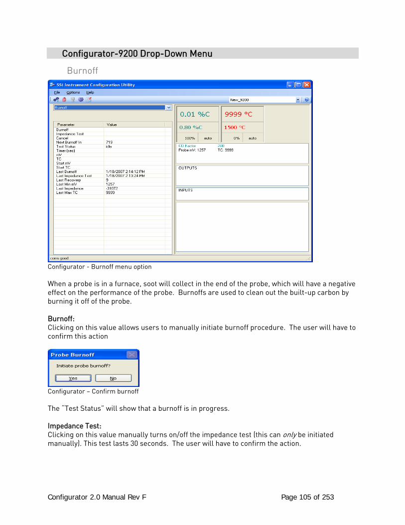
Configurator 2.0 Manual Rev F Page 105 of 253
Configurator-9200 Drop-Down Menu
Burnoff
Configurator - Burnoff menu option When a probe is in a furnace, soot will collect in the end of the probe, which will have a negative effect on the performance of the probe. Burnoffs are used to clean out the built-up carbon by burning it off of the probe. Burnoff: Clicking on this value allows users to manually initiate burnoff procedure. The user will have to confirm this action
Configurator – Confirm burnoff The “Test Status” will show that a burnoff is in progress. Impedance Test: Clicking on this value manually turns on/off the impedance test (this can only be initiated manually). This test lasts 30 seconds. The user will have to confirm the action.
Configurator 2.0 Manual Rev F Page 106 of 253
Configurator – Confirm impedance test The “Test Status” will then become “Impedance Test”. Cancel: Clicking on this value will manually turn off both the burnoff and the impedance test. The user will have to confirm this action.
Configurator – Confirm cancellation Next Burnoff: (shown in minutes): This value is a displayed calculation based on the burnoff time set in the Probe Burnoff Setup menu option. It displays the number of minutes until the next burnoff will be initiated. Test Status: This value displays the current testing status. The list of possible values are: Burnoff, Burnoff Recovery, Idle, Impedance Recovery, or Impedance Timer: This value shows the remaining time, in seconds, for the Burnoff / Impedance Test / Recoveries. MV: This value is a display of the current millivolt input value during a burnoff or impedance test. TC: This value is a display of the current probe thermocouple input value during a burnoff or impedance test. Start mV: This value is a display of the millivolt input value at the beginning of the Burnoff or impedance test. . Start TC: This value is a display of the probe thermocouple value at the beginning of the burnoff or impedance test. Last Burnoff: This value shows the date and time of the last burnoff.
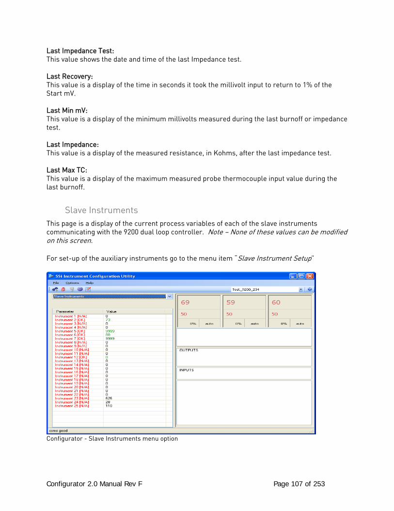
Configurator 2.0 Manual Rev F Page 107 of 253
Last Impedance Test: This value shows the date and time of the last Impedance test. Last Recovery: This value is a display of the time in seconds it took the millivolt input to return to 1% of the Start mV. Last Min mV: This value is a display of the minimum millivolts measured during the last burnoff or impedance test. Last Impedance: This value is a display of the measured resistance, in Kohms, after the last impedance test. Last Max TC: This value is a display of the maximum measured probe thermocouple input value during the last burnoff.
Slave Instruments This page is a display of the current process variables of each of the slave instruments communicating with the 9200 dual loop controller. Note – None of these values can be modified on this screen. For set-up of the auxiliary instruments go to the menu item “Slave Instrument Setup”
Configurator - Slave Instruments menu option
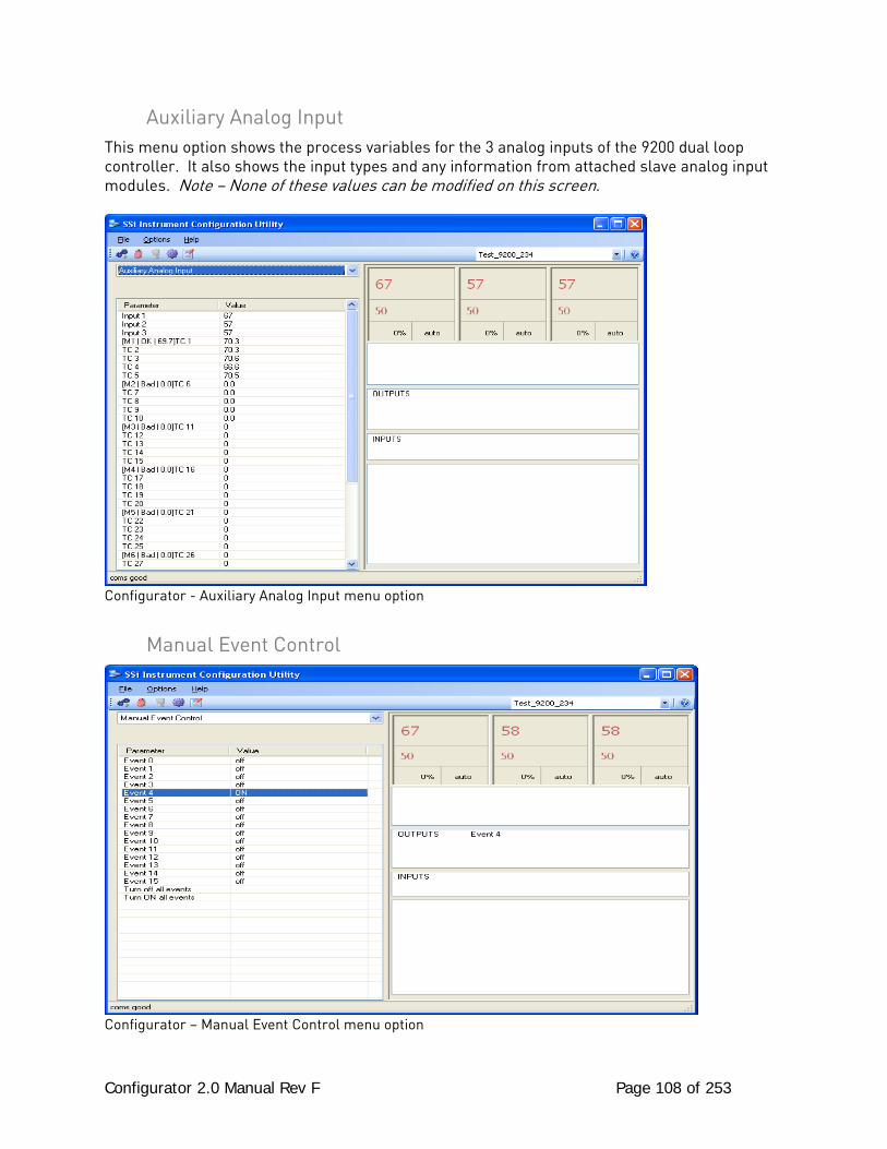
Configurator 2.0 Manual Rev F Page 108 of 253
Auxiliary Analog Input This menu option shows the process variables for the 3 analog inputs of the 9200 dual loop controller. It also shows the input types and any information from attached slave analog input modules. Note – None of these values can be modified on this screen.
Configurator - Auxiliary Analog Input menu option
Manual Event Control
Configurator – Manual Event Control menu option
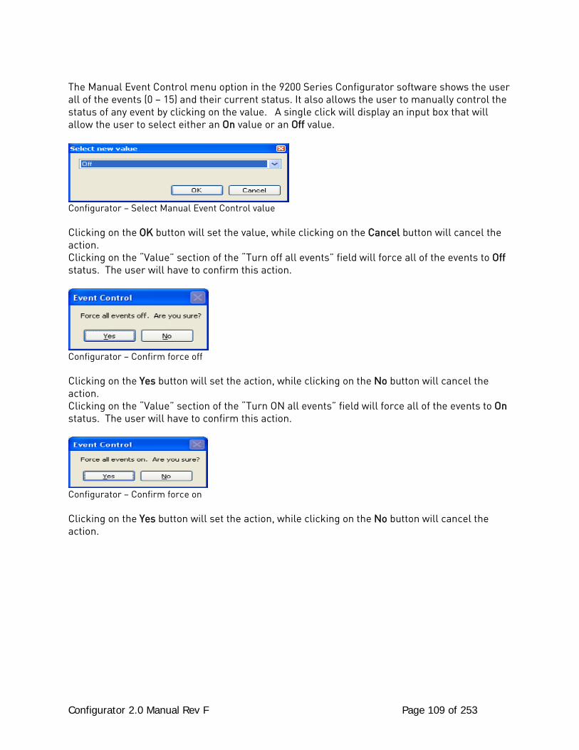
Configurator 2.0 Manual Rev F Page 109 of 253
The Manual Event Control menu option in the 9200 Series Configurator software shows the user all of the events (0 – 15) and their current status. It also allows the user to manually control the status of any event by clicking on the value. A single click will display an input box that will allow the user to select either an On value or an Off value.
Configurator – Select Manual Event Control value Clicking on the OK button will set the value, while clicking on the Cancel button will cancel the action. Clicking on the “Value” section of the “Turn off all events” field will force all of the events to Off status. The user will have to confirm this action.
Configurator – Confirm force off Clicking on the Yes button will set the action, while clicking on the No button will cancel the action. Clicking on the “Value” section of the “Turn ON all events” field will force all of the events to On status. The user will have to confirm this action.
Configurator – Confirm force on Clicking on the Yes button will set the action, while clicking on the No button will cancel the action.
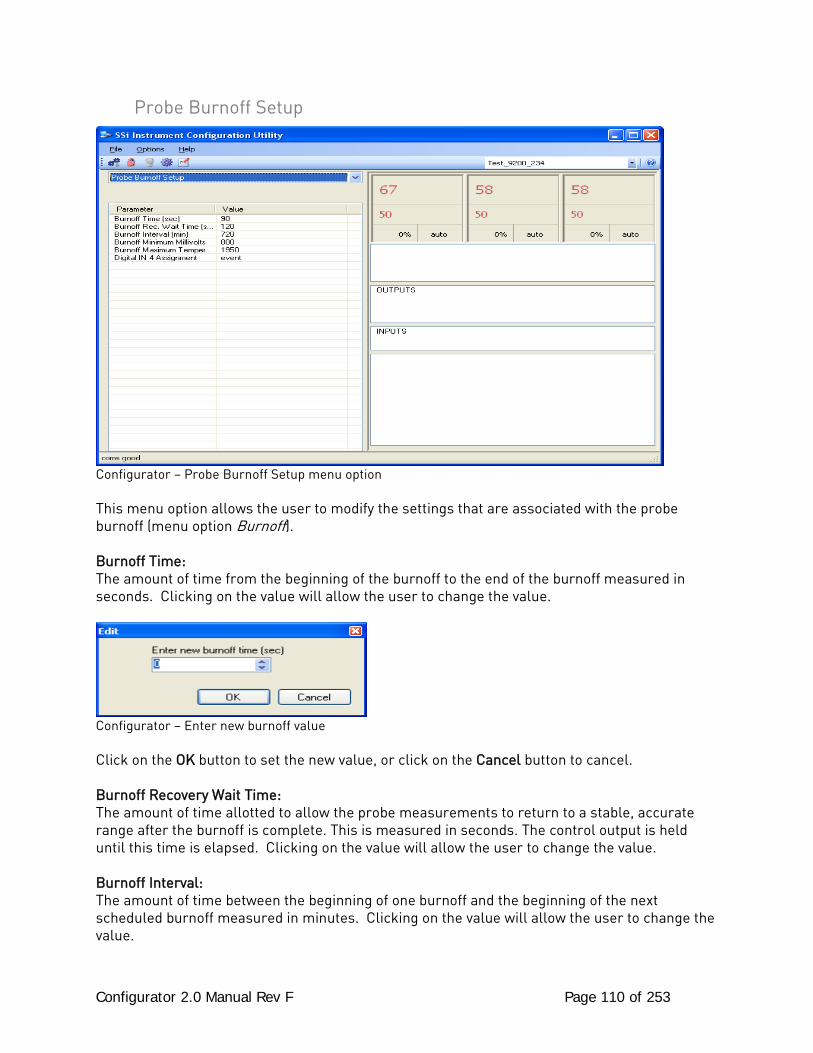
Configurator 2.0 Manual Rev F Page 110 of 253
Probe Burnoff Setup
Configurator – Probe Burnoff Setup menu option This menu option allows the user to modify the settings that are associated with the probe burnoff (menu option Burnoff). Burnoff Time: The amount of time from the beginning of the burnoff to the end of the burnoff measured in seconds. Clicking on the value will allow the user to change the value.
Configurator – Enter new burnoff value Click on the OK button to set the new value, or click on the Cancel button to cancel. Burnoff Recovery Wait Time: The amount of time allotted to allow the probe measurements to return to a stable, accurate range after the burnoff is complete. This is measured in seconds. The control output is held until this time is elapsed. Clicking on the value will allow the user to change the value. Burnoff Interval: The amount of time between the beginning of one burnoff and the beginning of the next scheduled burnoff measured in minutes. Clicking on the value will allow the user to change the value.
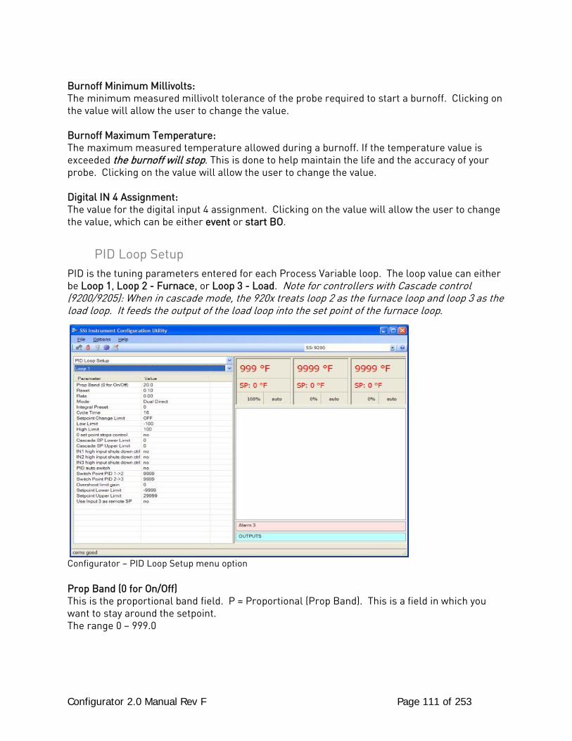
Configurator 2.0 Manual Rev F Page 111 of 253
Burnoff Minimum Millivolts: The minimum measured millivolt tolerance of the probe required to start a burnoff. Clicking on the value will allow the user to change the value. Burnoff Maximum Temperature: The maximum measured temperature allowed during a burnoff. If the temperature value is exceeded the burnoff will stop. This is done to help maintain the life and the accuracy of your probe. Clicking on the value will allow the user to change the value. Digital IN 4 Assignment: The value for the digital input 4 assignment. Clicking on the value will allow the user to change the value, which can be either event or start BO.
PID Loop Setup PID is the tuning parameters entered for each Process Variable loop. The loop value can either be Loop 1, Loop 2 - Furnace, or Loop 3 - Load. Note for controllers with Cascade control (9200/9205): When in cascade mode, the 920x treats loop 2 as the furnace loop and loop 3 as the load loop. It feeds the output of the load loop into the set point of the furnace loop.
Configurator – PID Loop Setup menu option Prop Band (0 for On/Off) This is the proportional band field. P = Proportional (Prop Band). This is a field in which you want to stay around the setpoint. The range 0 – 999.0
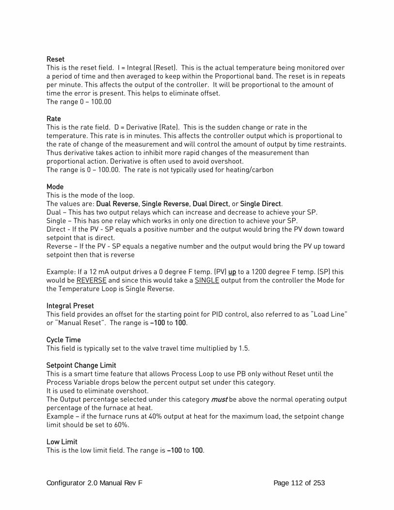
Configurator 2.0 Manual Rev F Page 112 of 253
Reset This is the reset field. I = Integral (Reset). This is the actual temperature being monitored over a period of time and then averaged to keep within the Proportional band. The reset is in repeats per minute. This affects the output of the controller. It will be proportional to the amount of time the error is present. This helps to eliminate offset. The range 0 – 100.00 Rate This is the rate field. D = Derivative (Rate). This is the sudden change or rate in the temperature. This rate is in minutes. This affects the controller output which is proportional to the rate of change of the measurement and will control the amount of output by time restraints. Thus derivative takes action to inhibit more rapid changes of the measurement than proportional action. Derivative is often used to avoid overshoot. The range is 0 – 100.00. The rate is not typically used for heating/carbon Mode This is the mode of the loop. The values are: Dual Reverse, Single Reverse, Dual Direct, or Single Direct. Dual – This has two output relays which can increase and decrease to achieve your SP. Single – This has one relay which works in only one direction to achieve your SP. Direct - If the PV - SP equals a positive number and the output would bring the PV down toward setpoint that is direct. Reverse – If the PV - SP equals a negative number and the output would bring the PV up toward setpoint then that is reverse Example: If a 12 mA output drives a 0 degree F temp. (PV) up to a 1200 degree F temp. (SP) this would be REVERSE and since this would take a SINGLE output from the controller the Mode for the Temperature Loop is Single Reverse. Integral Preset This field provides an offset for the starting point for PID control, also referred to as “Load Line” or “Manual Reset”. The range is –100 to 100. Cycle Time This field is typically set to the valve travel time multiplied by 1.5. Setpoint Change Limit This is a smart time feature that allows Process Loop to use PB only without Reset until the Process Variable drops below the percent output set under this category. It is used to eliminate overshoot. The Output percentage selected under this category must be above the normal operating output percentage of the furnace at heat. Example – if the furnace runs at 40% output at heat for the maximum load, the setpoint change limit should be set to 60%. Low Limit This is the low limit field. The range is –100 to 100.
Configurator 2.0 Manual Rev F Page 113 of 253
High Limit This is the high limit field. The range is –100 to 100. 0 Setpoint Stops Control If the Setpoint is zero, then all outputs are turned off. The option is either Yes or No. Cascade SP Lower Limit: This is the cascade setpoint low limit. The 9205 uses the difference between the cascade SP lower limit and the cascade SP upper limit and multiplies that value by the % output of the load loop. It then offsets this value by the cascade SP lower limit and feeds the furnace loop this value as a setpoint. Cascade SP Upper Limit: This is the cascade setpoint upper limit. The 9205 uses the difference between the cascade SP lower limit and the cascade SP upper limit and multiplies that value by the % output of the load loop. It then offsets this value by the cascade SP lower limit and feeds the furnace loop this value as a setpoint. Example: Cascade SP Lower Limit: 0 Cascade SP Upper Limit: 2000 The load has a setpoint of 1700 and it is at 37 % output. The furnace setpoint will be calculated as follows: (2000 – 0) * 0.37 + 0 = 740. IN1 high limit shuts down ctrl If input 1’s high limit is reached, then all outputs are turned off. The value can either be Yes or No. IN2 high limit shuts down ctrl If input 2’s high limit is reached, then all outputs are turned off. The value can either be Yes or No. IN3 high limit shuts down ctrl If input 3’s high limit is reached, then all outputs are turned off. The value can either be Yes or No. PID Auto Switch This is the PID auto switch field. The value can either be Yes or No. Switch Point PID 1 -> 2 This is the PID Switch Point field. The range is –300 to 4000. Switch Point PID 2 -> 3 This is the PID Switch Point field. The range is –300 to 4000. Overshoot Limit Gain This is the Overshoot limit gain field. When calculating the control action sometimes the calculation would call for more than 100% which is not possible. The output is limited to 100%, or whatever was set in the High Limit field. The difference of the unlimited minus the limited is
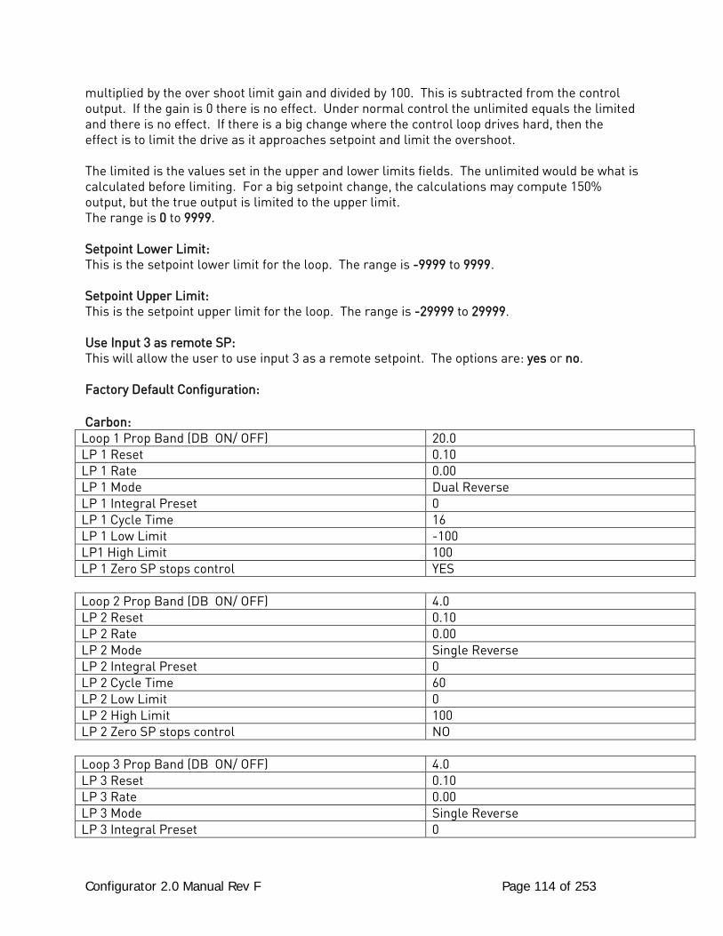
Configurator 2.0 Manual Rev F Page 114 of 253
multiplied by the over shoot limit gain and divided by 100. This is subtracted from the control output. If the gain is 0 there is no effect. Under normal control the unlimited equals the limited and there is no effect. If there is a big change where the control loop drives hard, then the effect is to limit the drive as it approaches setpoint and limit the overshoot. The limited is the values set in the upper and lower limits fields. The unlimited would be what is calculated before limiting. For a big setpoint change, the calculations may compute 150% output, but the true output is limited to the upper limit. The range is 0 to 9999. Setpoint Lower Limit: This is the setpoint lower limit for the loop. The range is -9999 to 9999. Setpoint Upper Limit: This is the setpoint upper limit for the loop. The range is -29999 to 29999. Use Input 3 as remote SP: This will allow the user to use input 3 as a remote setpoint. The options are: yes or no. Factory Default Configuration: Carbon:
Loop 1 Prop Band (DB ON/ OFF) 20.0 LP 1 Reset 0.10 LP 1 Rate 0.00 LP 1 Mode Dual Reverse LP 1 Integral Preset 0 LP 1 Cycle Time 16 LP 1 Low Limit -100 LP1 High Limit 100 LP 1 Zero SP stops control YES
Loop 2 Prop Band (DB ON/ OFF) 4.0 LP 2 Reset 0.10 LP 2 Rate 0.00 LP 2 Mode Single Reverse LP 2 Integral Preset 0 LP 2 Cycle Time 60 LP 2 Low Limit 0 LP 2 High Limit 100 LP 2 Zero SP stops control NO
Loop 3 Prop Band (DB ON/ OFF) 4.0 LP 3 Reset 0.10 LP 3 Rate 0.00 LP 3 Mode Single Reverse LP 3 Integral Preset 0
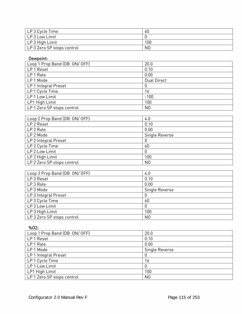
Configurator 2.0 Manual Rev F Page 115 of 253
LP 3 Cycle Time 60 LP 3 Low Limit 0 LP 3 High Limit 100 LP 3 Zero SP stops control NO Dewpoint:
Loop 1 Prop Band (DB ON/ OFF) 20.0 LP 1 Reset 0.10 LP 1 Rate 0.00 LP 1 Mode Dual Direct LP 1 Integral Preset 0 LP 1 Cycle Time 16 LP 1 Low Limit -100 LP1 High Limit 100 LP 1 Zero SP stops control NO
Loop 2 Prop Band (DB ON/ OFF) 4.0 LP 2 Reset 0.10 LP 2 Rate 0.00 LP 2 Mode Single Reverse LP 2 Integral Preset 0 LP 2 Cycle Time 60 LP 2 Low Limit 0 LP 2 High Limit 100 LP 2 Zero SP stops control NO
Loop 3 Prop Band (DB ON/ OFF) 4.0 LP 3 Reset 0.10 LP 3 Rate 0.00 LP 3 Mode Single Reverse LP 3 Integral Preset 0 LP 3 Cycle Time 60 LP 3 Low Limit 0 LP 3 High Limit 100 LP 3 Zero SP stops control NO %O2:
Loop 1 Prop Band (DB ON/ OFF) 20.0 LP 1 Reset 0.10 LP 1 Rate 0.00 LP 1 Mode Single Reverse LP 1 Integral Preset 0 LP 1 Cycle Time 16 LP 1 Low Limit 0 LP1 High Limit 100 LP 1 Zero SP stops control NO

Configurator 2.0 Manual Rev F Page 116 of 253
Loop 2 Prop Band (DB ON/ OFF) 4.0 LP 2 Reset 0.10 LP 2 Rate 0.00 LP 2 Mode Single Reverse LP 2 Integral Preset 0 LP 2 Cycle Time 60 LP 2 Low Limit 0 LP 2 High Limit 100 LP 2 Zero SP stops control NO
Loop 3 Prop Band (DB ON/ OFF) 4.0 LP 3 Reset 0.10 LP 3 Rate 0.00 LP 3 Mode Single Reverse LP 3 Integral Preset 0 LP 3 Cycle Time 60 LP 3 Low Limit 0 LP 3 High Limit 100 LP 3 Zero SP stops control NO mV:
Loop 1 Prop Band (DB ON/ OFF) 20.0 LP 1 Reset 0.10 LP 1 Rate 0.00 LP 1 Mode Dual Reverse LP 1 Integral Preset 0 LP 1 Cycle Time 16 LP 1 Low Limit -100 LP1 High Limit 100 LP 1 Zero SP stops control YES
Loop 2 Prop Band (DB ON/ OFF) 4.0 LP 2 Reset 0.10 LP 2 Rate 0.00 LP 2 Mode Single Reverse LP 2 Integral Preset 0 LP 2 Cycle Time 60 LP 2 Low Limit 0 LP 2 High Limit 100 LP 2 Zero SP stops control NO
Loop 3 Prop Band (DB ON/ OFF) 4.0 LP 3 Reset 0.10 LP 3 Rate 0.00 LP 3 Mode Single Reverse LP 3 Integral Preset 0
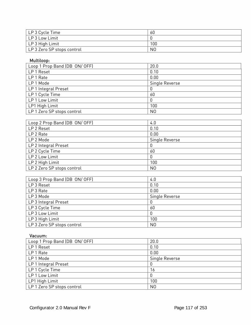
Configurator 2.0 Manual Rev F Page 117 of 253
LP 3 Cycle Time 60 LP 3 Low Limit 0 LP 3 High Limit 100 LP 3 Zero SP stops control NO Multiloop:
Loop 1 Prop Band (DB ON/ OFF) 20.0 LP 1 Reset 0.10 LP 1 Rate 0.00 LP 1 Mode Single Reverse LP 1 Integral Preset 0 LP 1 Cycle Time 60 LP 1 Low Limit 0 LP1 High Limit 100 LP 1 Zero SP stops control NO
Loop 2 Prop Band (DB ON/ OFF) 4.0 LP 2 Reset 0.10 LP 2 Rate 0.00 LP 2 Mode Single Reverse LP 2 Integral Preset 0 LP 2 Cycle Time 60 LP 2 Low Limit 0 LP 2 High Limit 100 LP 2 Zero SP stops control NO
Loop 3 Prop Band (DB ON/ OFF) 4.0 LP 3 Reset 0.10 LP 3 Rate 0.00 LP 3 Mode Single Reverse LP 3 Integral Preset 0 LP 3 Cycle Time 60 LP 3 Low Limit 0 LP 3 High Limit 100 LP 3 Zero SP stops control NO Vacuum:
Loop 1 Prop Band (DB ON/ OFF) 20.0 LP 1 Reset 0.10 LP 1 Rate 0.00 LP 1 Mode Single Reverse LP 1 Integral Preset 0 LP 1 Cycle Time 16 LP 1 Low Limit 0 LP1 High Limit 100 LP 1 Zero SP stops control NO
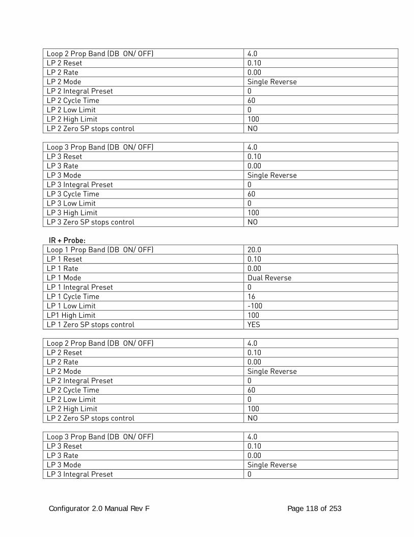
Configurator 2.0 Manual Rev F Page 118 of 253
Loop 2 Prop Band (DB ON/ OFF) 4.0 LP 2 Reset 0.10 LP 2 Rate 0.00 LP 2 Mode Single Reverse LP 2 Integral Preset 0 LP 2 Cycle Time 60 LP 2 Low Limit 0 LP 2 High Limit 100 LP 2 Zero SP stops control NO
Loop 3 Prop Band (DB ON/ OFF) 4.0 LP 3 Reset 0.10 LP 3 Rate 0.00 LP 3 Mode Single Reverse LP 3 Integral Preset 0 LP 3 Cycle Time 60 LP 3 Low Limit 0 LP 3 High Limit 100 LP 3 Zero SP stops control NO IR + Probe:
Loop 1 Prop Band (DB ON/ OFF) 20.0 LP 1 Reset 0.10 LP 1 Rate 0.00 LP 1 Mode Dual Reverse LP 1 Integral Preset 0 LP 1 Cycle Time 16 LP 1 Low Limit -100 LP1 High Limit 100 LP 1 Zero SP stops control YES
Loop 2 Prop Band (DB ON/ OFF) 4.0 LP 2 Reset 0.10 LP 2 Rate 0.00 LP 2 Mode Single Reverse LP 2 Integral Preset 0 LP 2 Cycle Time 60 LP 2 Low Limit 0 LP 2 High Limit 100 LP 2 Zero SP stops control NO
Loop 3 Prop Band (DB ON/ OFF) 4.0 LP 3 Reset 0.10 LP 3 Rate 0.00 LP 3 Mode Single Reverse LP 3 Integral Preset 0
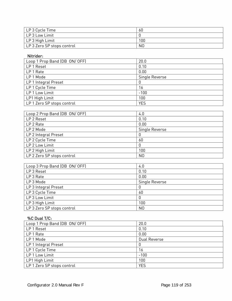
Configurator 2.0 Manual Rev F Page 119 of 253
LP 3 Cycle Time 60 LP 3 Low Limit 0 LP 3 High Limit 100 LP 3 Zero SP stops control NO Nitrider:
Loop 1 Prop Band (DB ON/ OFF) 20.0 LP 1 Reset 0.10 LP 1 Rate 0.00 LP 1 Mode Single Reverse LP 1 Integral Preset 0 LP 1 Cycle Time 16 LP 1 Low Limit -100 LP1 High Limit 100 LP 1 Zero SP stops control YES
Loop 2 Prop Band (DB ON/ OFF) 4.0 LP 2 Reset 0.10 LP 2 Rate 0.00 LP 2 Mode Single Reverse LP 2 Integral Preset 0 LP 2 Cycle Time 60 LP 2 Low Limit 0 LP 2 High Limit 100 LP 2 Zero SP stops control NO
Loop 3 Prop Band (DB ON/ OFF) 4.0 LP 3 Reset 0.10 LP 3 Rate 0.00 LP 3 Mode Single Reverse LP 3 Integral Preset 0 LP 3 Cycle Time 60 LP 3 Low Limit 0 LP 3 High Limit 100 LP 3 Zero SP stops control NO %C Dual T/C:
Loop 1 Prop Band (DB ON/ OFF) 20.0 LP 1 Reset 0.10 LP 1 Rate 0.00 LP 1 Mode Dual Reverse LP 1 Integral Preset 0 LP 1 Cycle Time 16 LP 1 Low Limit -100 LP1 High Limit 100 LP 1 Zero SP stops control YES
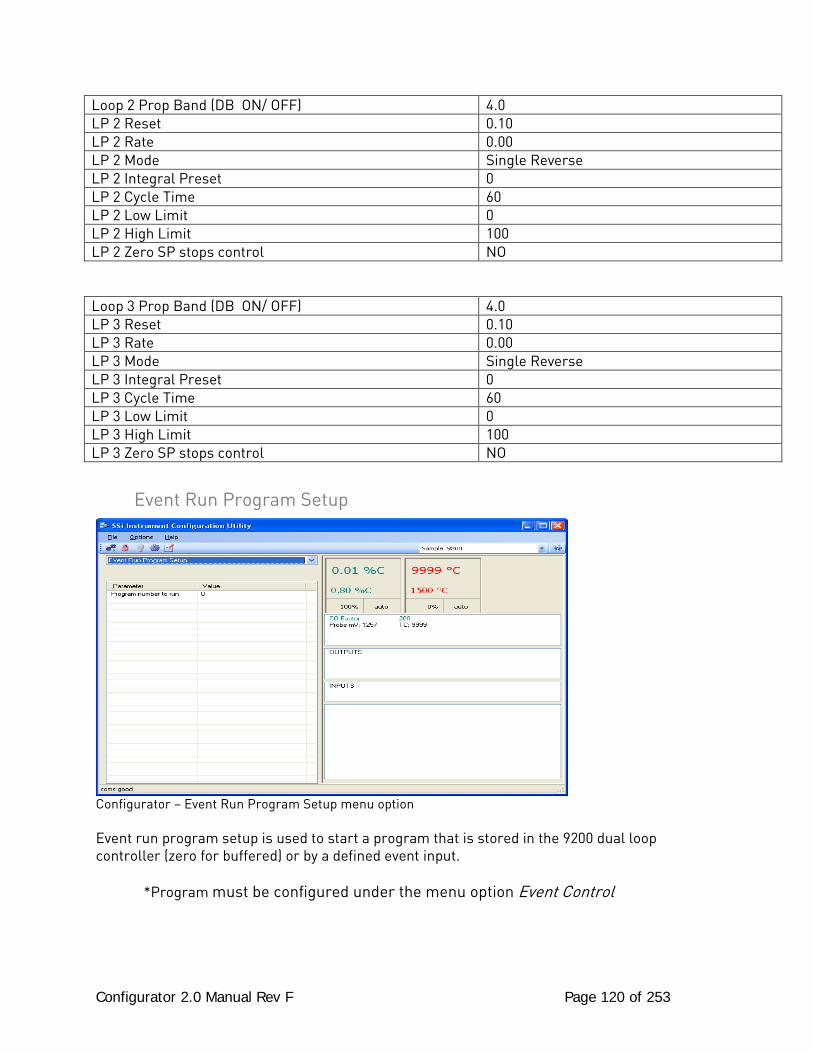
Configurator 2.0 Manual Rev F Page 120 of 253
Loop 2 Prop Band (DB ON/ OFF) 4.0 LP 2 Reset 0.10 LP 2 Rate 0.00 LP 2 Mode Single Reverse LP 2 Integral Preset 0 LP 2 Cycle Time 60 LP 2 Low Limit 0 LP 2 High Limit 100 LP 2 Zero SP stops control NO
Loop 3 Prop Band (DB ON/ OFF) 4.0 LP 3 Reset 0.10 LP 3 Rate 0.00 LP 3 Mode Single Reverse LP 3 Integral Preset 0 LP 3 Cycle Time 60 LP 3 Low Limit 0 LP 3 High Limit 100 LP 3 Zero SP stops control NO
Event Run Program Setup
Configurator – Event Run Program Setup menu option Event run program setup is used to start a program that is stored in the 9200 dual loop controller (zero for buffered) or by a defined event input.
*Program must be configured under the menu option Event Control
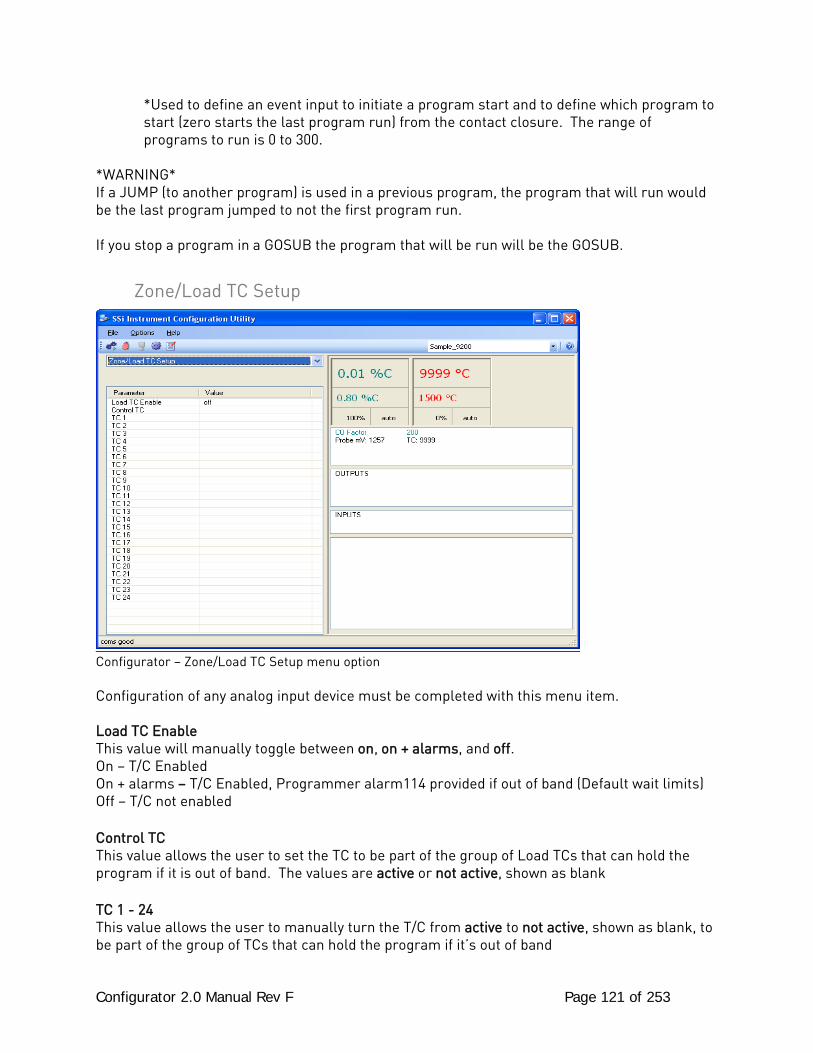
Configurator 2.0 Manual Rev F Page 121 of 253
*Used to define an event input to initiate a program start and to define which program to start (zero starts the last program run) from the contact closure. The range of programs to run is 0 to 300.
*WARNING* If a JUMP (to another program) is used in a previous program, the program that will run would be the last program jumped to not the first program run. If you stop a program in a GOSUB the program that will be run will be the GOSUB.
Zone/Load TC Setup
Configurator – Zone/Load TC Setup menu option Configuration of any analog input device must be completed with this menu item. Load TC Enable This value will manually toggle between on, on + alarms, and off. On – T/C Enabled On + alarms – T/C Enabled, Programmer alarm114 provided if out of band (Default wait limits) Off – T/C not enabled Control TC This value allows the user to set the TC to be part of the group of Load TCs that can hold the program if it is out of band. The values are active or not active, shown as blank TC 1 - 24 This value allows the user to manually turn the T/C from active to not active, shown as blank, to be part of the group of TCs that can hold the program if it’s out of band
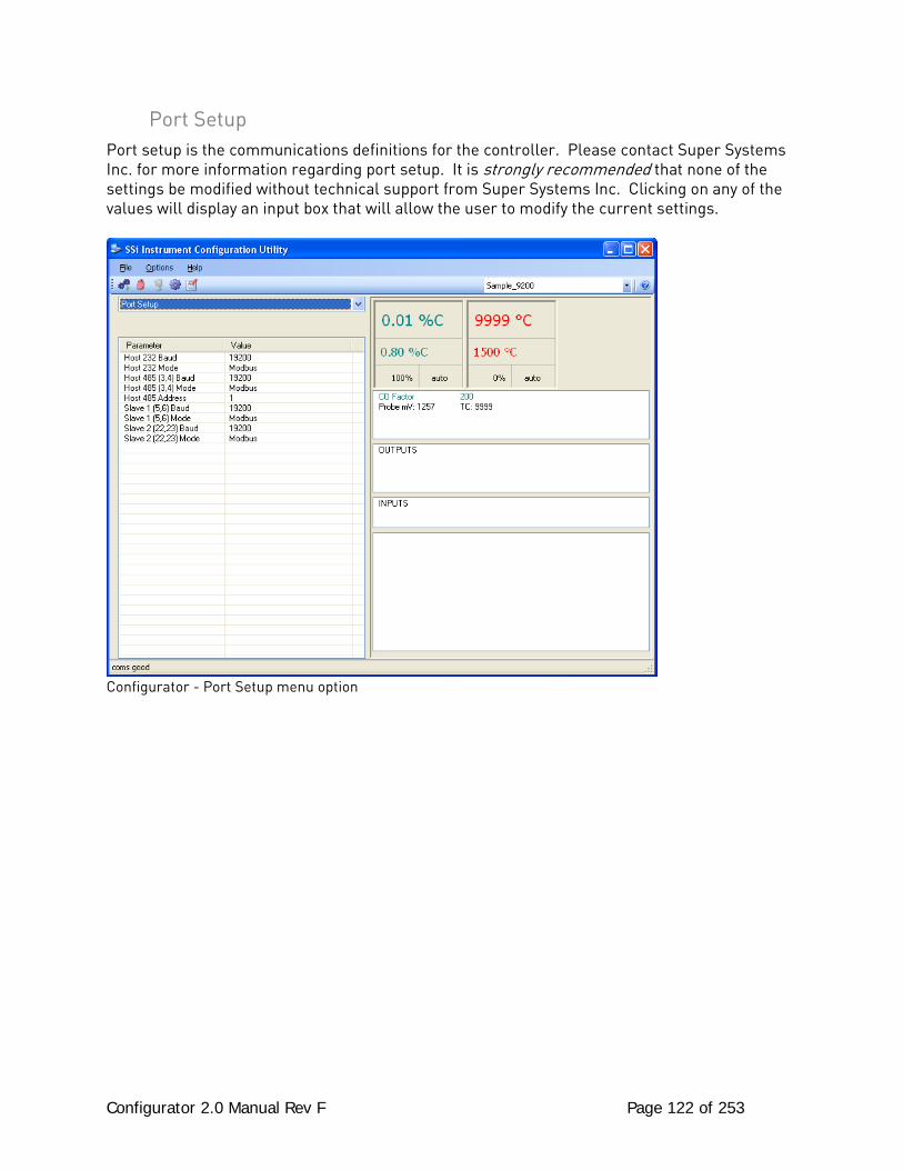
Configurator 2.0 Manual Rev F Page 122 of 253
Port Setup Port setup is the communications definitions for the controller. Please contact Super Systems Inc. for more information regarding port setup. It is strongly recommended that none of the settings be modified without technical support from Super Systems Inc. Clicking on any of the values will display an input box that will allow the user to modify the current settings.
Configurator - Port Setup menu option
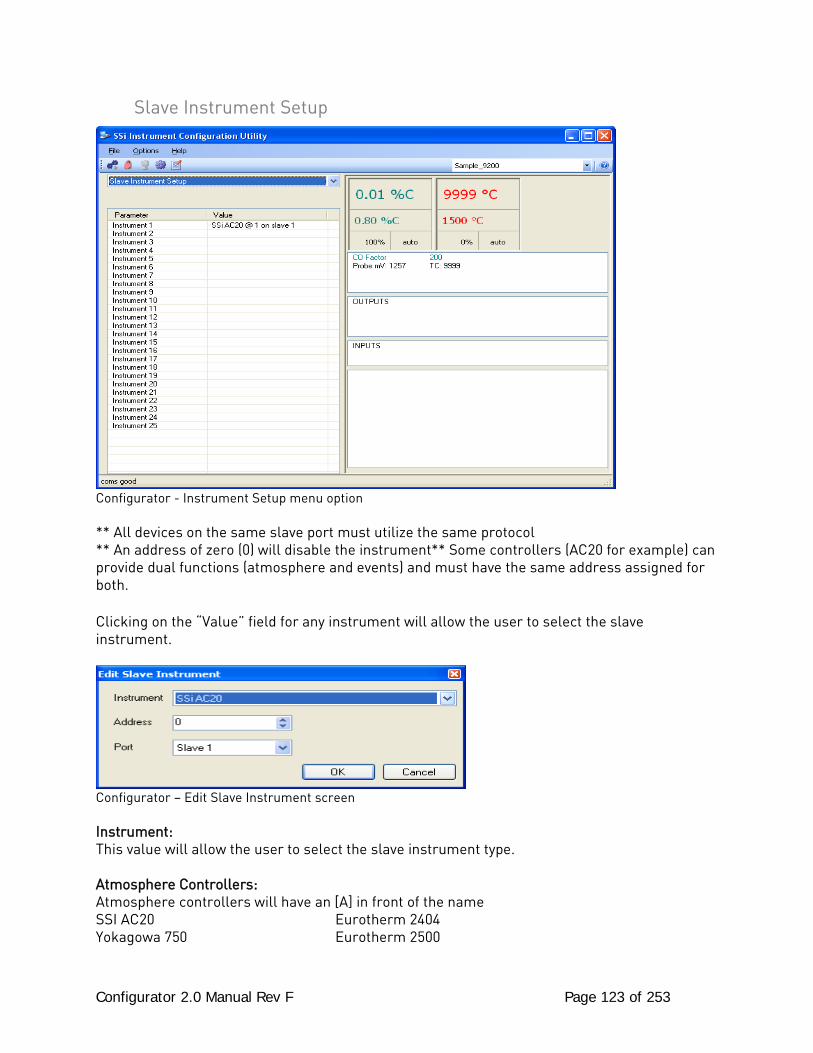
Configurator 2.0 Manual Rev F Page 123 of 253
Slave Instrument Setup
Configurator - Instrument Setup menu option ** All devices on the same slave port must utilize the same protocol ** An address of zero (0) will disable the instrument** Some controllers (AC20 for example) can provide dual functions (atmosphere and events) and must have the same address assigned for both. Clicking on the “Value” field for any instrument will allow the user to select the slave instrument.
Configurator – Edit Slave Instrument screen Instrument: This value will allow the user to select the slave instrument type. Atmosphere Controllers: Atmosphere controllers will have an [A] in front of the name SSI AC20 Eurotherm 2404 Yokagowa 750 Eurotherm 2500
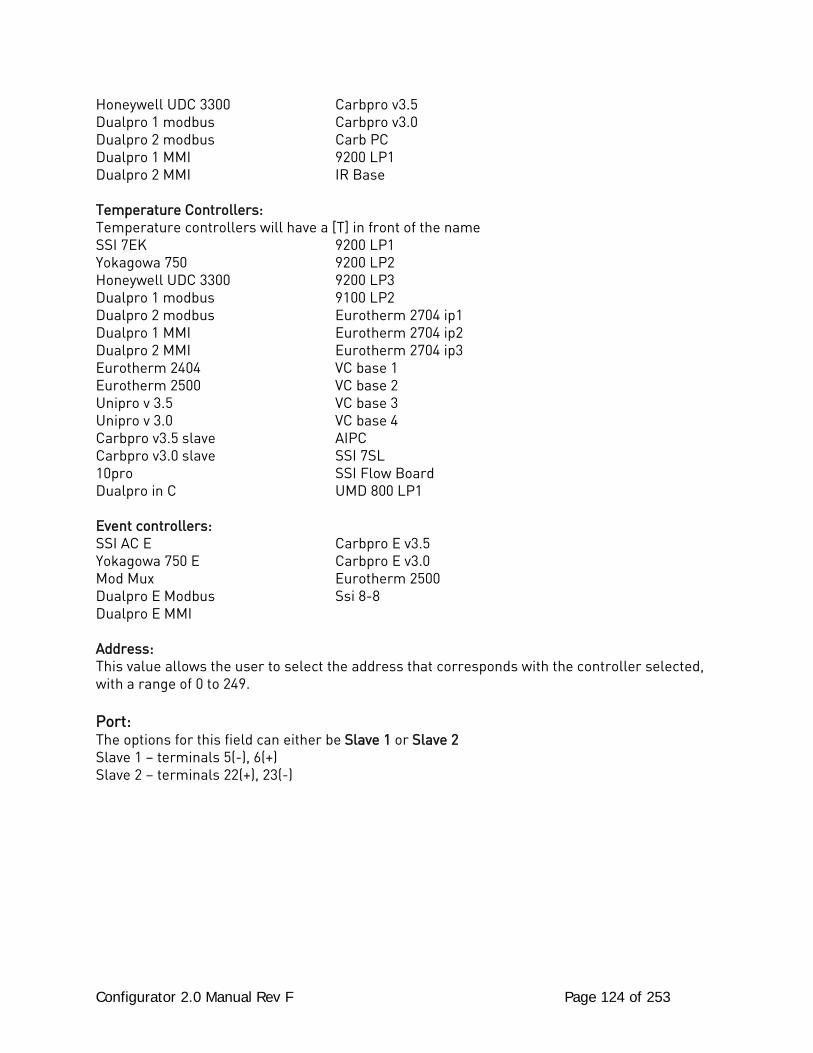
Configurator 2.0 Manual Rev F Page 124 of 253
Honeywell UDC 3300 Carbpro v3.5 Dualpro 1 modbus Carbpro v3.0 Dualpro 2 modbus Carb PC Dualpro 1 MMI 9200 LP1 Dualpro 2 MMI IR Base Temperature Controllers: Temperature controllers will have a [T] in front of the name SSI 7EK 9200 LP1 Yokagowa 750 9200 LP2 Honeywell UDC 3300 9200 LP3 Dualpro 1 modbus 9100 LP2 Dualpro 2 modbus Eurotherm 2704 ip1 Dualpro 1 MMI Eurotherm 2704 ip2 Dualpro 2 MMI Eurotherm 2704 ip3 Eurotherm 2404 VC base 1 Eurotherm 2500 VC base 2 Unipro v 3.5 VC base 3 Unipro v 3.0 VC base 4 Carbpro v3.5 slave AIPC Carbpro v3.0 slave SSI 7SL 10pro SSI Flow Board Dualpro in C UMD 800 LP1 Event controllers: SSI AC E Carbpro E v3.5 Yokagowa 750 E Carbpro E v3.0 Mod Mux Eurotherm 2500 Dualpro E Modbus Ssi 8-8 Dualpro E MMI Address: This value allows the user to select the address that corresponds with the controller selected, with a range of 0 to 249. Port: The options for this field can either be Slave 1 or Slave 2 Slave 1 – terminals 5(-), 6(+) Slave 2 – terminals 22(+), 23(-)
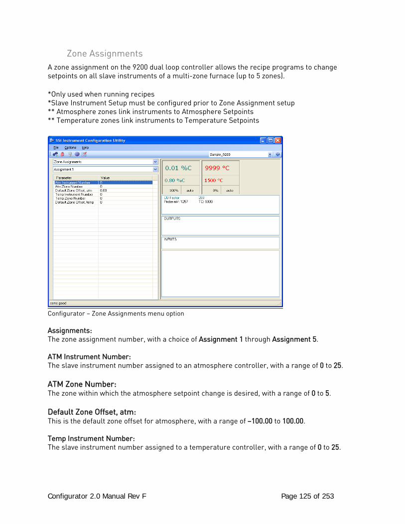
Configurator 2.0 Manual Rev F Page 125 of 253
Zone Assignments A zone assignment on the 9200 dual loop controller allows the recipe programs to change setpoints on all slave instruments of a multi-zone furnace (up to 5 zones). *Only used when running recipes *Slave Instrument Setup must be configured prior to Zone Assignment setup ** Atmosphere zones link instruments to Atmosphere Setpoints ** Temperature zones link instruments to Temperature Setpoints
Configurator – Zone Assignments menu option Assignments: The zone assignment number, with a choice of Assignment 1 through Assignment 5. ATM Instrument Number: The slave instrument number assigned to an atmosphere controller, with a range of 0 to 25. ATM Zone Number: The zone within which the atmosphere setpoint change is desired, with a range of 0 to 5. Default Zone Offset, atm: This is the default zone offset for atmosphere, with a range of –100.00 to 100.00. Temp Instrument Number: The slave instrument number assigned to a temperature controller, with a range of 0 to 25.
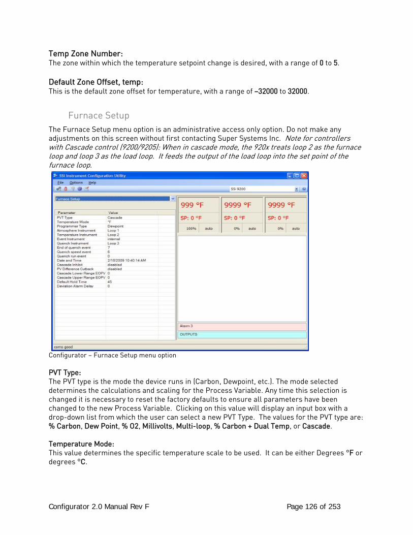
Configurator 2.0 Manual Rev F Page 126 of 253
Temp Zone Number: The zone within which the temperature setpoint change is desired, with a range of 0 to 5. Default Zone Offset, temp: This is the default zone offset for temperature, with a range of –32000 to 32000.
Furnace Setup The Furnace Setup menu option is an administrative access only option. Do not make any adjustments on this screen without first contacting Super Systems Inc. Note for controllers with Cascade control (9200/9205): When in cascade mode, the 920x treats loop 2 as the furnace loop and loop 3 as the load loop. It feeds the output of the load loop into the set point of the furnace loop.
Configurator – Furnace Setup menu option PVT Type: The PVT type is the mode the device runs in (Carbon, Dewpoint, etc.). The mode selected determines the calculations and scaling for the Process Variable. Any time this selection is changed it is necessary to reset the factory defaults to ensure all parameters have been changed to the new Process Variable. Clicking on this value will display an input box with a drop-down list from which the user can select a new PVT Type. The values for the PVT type are: % Carbon, Dew Point, % O2, Millivolts, Multi-loop, % Carbon + Dual Temp, or Cascade. Temperature Mode: This value determines the specific temperature scale to be used. It can be either Degrees °F or degrees °C.
Configurator 2.0 Manual Rev F Page 127 of 253
Programmer Type: Displays programmer types and allows for a change in control mode. The values for the Programmer Type are: % Carbon, Dew Point, % O2, Millivolts, Temperature Only, Dual Temperature, Vacuum, Probe + IR, Nitrider, Carbon + Dual Temperature, or Cascade. Atmosphere Instrument: Allows for a slave instrument (or internal) to be the defined atmosphere control device. The types of instruments are: Internal Loop 1 – Internal Loop 3, Instrument 1 – Instrument 25. Temperature Instrument: Allows for a slave instrument (or internal) to be the defined temperature control device. The types of instruments are: Internal Loop 1 – Internal Loop 3, Instrument 1 – Instrument 25. Event Instrument: Allows for a slave instrument (or internal) to be the defined event control device. The types of instruments are: Internal, Instrument 1 – Instrument 25. Quench Instrument: Allows for slave instrument (or internal) to be the defined quench control device. The types of instruments are: Internal Loop 1 – Internal Loop 3, Instrument 1 – Instrument 25. End of Quench Event: Tells the programmer which event to signal end of quench (related to which relay it is assigned). The list of possible values is: 0 – 14. Quench Speed Event: Tells the programmer which event will signal the quench speed. The list of possible values is: 0 – 14. Quench Run Event: Tells the programmer which event will signal quench run. The list of possible values is: 0 – 14. Date and Time: This value is the current date and time on the 9200 controller only (not the local computer or the touch screen, if applicable). Clicking on the “Value” column will allow the user to set a new date and time on the controller. Note: The date and time of the touch screen can be changed (if necessary) by selecting the date and time in the lower right corner on the touch screen under the menu. This can be reached by going through the menu, and shutting down the software. Then, at the CE screen the date and time can be changed by double taping the time in the bottom right corner and setting it, then select “apply”. For this to take effect the screen needs to be rebooted; on the older TPC 642 displays the registry needs to be saved under TPC Configuration icon, the Misc Tab and then reboot the touch screen. The date and time that is recorded on the flash card (and therefore the datalog data) is the date and time of the Advantech display not the controller.
Configurator 2.0 Manual Rev F Page 128 of 253
Cascade Inhibit: Note: This field is only applicable if the controller is in Cascade mode. This will turn cascade control on or off. When inhibit = enabled, the 9205 functions as a multi-loop controller with three control loops. The options are: enabled or disabled. PV Difference Cutback: Note: This field is only applicable if the controller is in Cascade Mode. This is used with the Cascade Lower Range EOPV and Cascade Upper Range EOPV to limit the absolute % output of the furnace loop. This will turn the PV difference cutback feature on or off. The options are: enabled or disabled. Cascade Lower Range EOPV: Note: This field is only applicable if the controller is in Cascade Mode. This is the cascade lower range end of PV difference. This is used with the PV Difference Cutback and Cascade Upper Range EOPV to limit the absolute % output of the furnace loop. Between the lower range EPOV and the upper range EOPV, there is a linear interpolation from 0 to the loop 2 output maximum (usually 100 %) that determines the maximum % output for the furnace loop. The range is -300 to 10000. Cascade Upper Range EOPV: Note: This field is only applicable if the controller is in Cascade Mode. This is the cascade upper range end of PV difference. This is used with the Cascade Lower Range EOPV and PV Difference Cutback to limit the absolute % output of the furnace loop. Between the lower range EPOV and the upper range EOPV, there is a linear interpolation from 0 to the loop 2 output maximum (usually 100 %) that determines the maximum % output for the furnace loop. The range is -300 to 10000. Example: With the lower EOPV set to 10 and the upper EOPV set to 110, if the load PV is 1700 and the furnace PV is 1710, the full 100% output is available. If the load PV is 1600 and the furnace PV is 1710, the furnace output will not go above 0%. If the load PV is 1655 and the furnace PV is 1710, the maximum output for the furnace loop will be limited to 55%: (1710 – 1655)/(110-10) * (1.0). Default Hold Time: This value is the default holding time for the furnace. The range is 0 to 10000. Deviation Alarm delay: This value is the delay for the alarm if a deviation alarm is detected. The range is 0 to 10000.
Default Wait Limits The 9200 dual loop controller uses default wait limits in conjunction with recipe programs. The wait limits are in place to help make sure a recipe will not continue to the next step until the temperature, atmosphere or both are within the specified range. The wait limits are both plus and minus the value of the setpoint specified in the recipe. You can define specific wait limits per program that supersede the defaults with the specific wait limit OP CODE per program (SETWAIT).
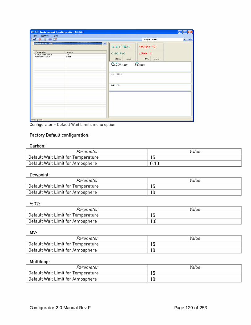
Configurator 2.0 Manual Rev F Page 129 of 253
Configurator – Default Wait Limits menu option Factory Default configuration: Carbon:
Parameter Value Default Wait Limit for Temperature 15 Default Wait Limit for Atmosphere 0.10 Dewpoint:
Parameter Value Default Wait Limit for Temperature 15 Default Wait Limit for Atmosphere 10 %O2:
Parameter Value Default Wait Limit for Temperature 15 Default Wait Limit for Atmosphere 1.0 MV:
Parameter Value Default Wait Limit for Temperature 15 Default Wait Limit for Atmosphere 10 Multiloop:
Parameter Value Default Wait Limit for Temperature 15 Default Wait Limit for Atmosphere 10
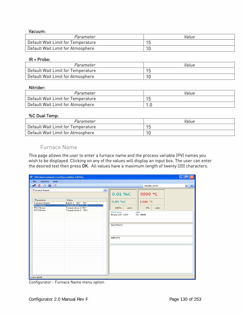
Configurator 2.0 Manual Rev F Page 130 of 253
Vacuum: Parameter Value
Default Wait Limit for Temperature 15 Default Wait Limit for Atmosphere 10 IR + Probe:
Parameter Value Default Wait Limit for Temperature 15 Default Wait Limit for Atmosphere 10 Nitrider:
Parameter Value Default Wait Limit for Temperature 15 Default Wait Limit for Atmosphere 1.0 %C Dual Temp:
Parameter Value Default Wait Limit for Temperature 15 Default Wait Limit for Atmosphere 10
Furnace Name This page allows the user to enter a furnace name and the process variable (PV) names you wish to be displayed. Clicking on any of the values will display an input box. The user can enter the desired text then press OK. All values have a maximum length of twenty (20) characters.
Configurator - Furnace Name menu option
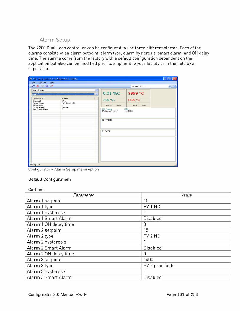
Configurator 2.0 Manual Rev F Page 131 of 253
Alarm Setup The 9200 Dual Loop controller can be configured to use three different alarms. Each of the alarms consists of an alarm setpoint, alarm type, alarm hysteresis, smart alarm, and ON delay time. The alarms come from the factory with a default configuration dependent on the application but also can be modified prior to shipment to your facility or in the field by a supervisor.
Configurator – Alarm Setup menu option Default Configuration: Carbon:
Parameter Value Alarm 1 setpoint 10 Alarm 1 type PV 1 NC Alarm 1 hysteresis 1 Alarm 1 Smart Alarm Disabled Alarm 1 ON delay time 0 Alarm 2 setpoint 15 Alarm 2 type PV 2 NC Alarm 2 hysteresis 1 Alarm 2 Smart Alarm Disabled Alarm 2 ON delay time 0 Alarm 3 setpoint 1400 Alarm 3 type PV 2 proc high Alarm 3 hysteresis 1 Alarm 3 Smart Alarm Disabled
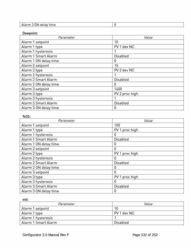
Configurator 2.0 Manual Rev F Page 132 of 253
Alarm 3 ON delay time 0 Dewpoint:
Parameter Value Alarm 1 setpoint 10 Alarm 1 type PV 1 dev NC Alarm 1 hysteresis 1 Alarm 1 Smart Alarm Disabled Alarm 1 ON delay time 0 Alarm 2 setpoint 15 Alarm 2 type PV 2 dev NC Alarm 2 hysteresis 1 Alarm 2 Smart Alarm Disabled Alarm 2 ON delay time 0 Alarm 3 setpoint 1400 Alarm 3 type PV 2 proc high Alarm 3 hysteresis 1 Alarm 3 Smart Alarm Disabled Alarm 3 ON delay time 0 %O2:
Parameter Value Alarm 1 setpoint 100 Alarm 1 type PV 1 proc high Alarm 1 hysteresis 0 Alarm 1 Smart Alarm Disabled Alarm 1 ON delay time 0 Alarm 2 setpoint 0 Alarm 2 type PV 1 proc high Alarm 2 hysteresis 0 Alarm 2 Smart Alarm Disabled Alarm 2 ON delay time 0 Alarm 3 setpoint 0 Alarm 3 type PV 1 proc high Alarm 3 hysteresis 0 Alarm 3 Smart Alarm Disabled Alarm 3 ON delay time 0 mV:
Parameter Value Alarm 1 setpoint 10 Alarm 1 type PV 1 dev NC Alarm 1 hysteresis 1 Alarm 1 Smart Alarm Disabled
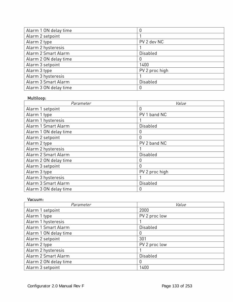
Configurator 2.0 Manual Rev F Page 133 of 253
Alarm 1 ON delay time 0 Alarm 2 setpoint 1 Alarm 2 type PV 2 dev NC Alarm 2 hysteresis 1 Alarm 2 Smart Alarm Disabled Alarm 2 ON delay time 0 Alarm 3 setpoint 1400 Alarm 3 type PV 2 proc high Alarm 3 hysteresis 1 Alarm 3 Smart Alarm Disabled Alarm 3 ON delay time 0 Multiloop:
Parameter Value Alarm 1 setpoint 0 Alarm 1 type PV 1 band NC Alarm 1 hysteresis 1 Alarm 1 Smart Alarm Disabled Alarm 1 ON delay time 0 Alarm 2 setpoint 0 Alarm 2 type PV 2 band NC Alarm 2 hysteresis 1 Alarm 2 Smart Alarm Disabled Alarm 2 ON delay time 0 Alarm 3 setpoint 0 Alarm 3 type PV 2 proc high Alarm 3 hysteresis 1 Alarm 3 Smart Alarm Disabled Alarm 3 ON delay time 0 Vacuum:
Parameter Value Alarm 1 setpoint 2000 Alarm 1 type PV 2 proc low Alarm 1 hysteresis 1 Alarm 1 Smart Alarm Disabled Alarm 1 ON delay time 0 Alarm 2 setpoint 301 Alarm 2 type PV 2 proc low Alarm 2 hysteresis 1 Alarm 2 Smart Alarm Disabled Alarm 2 ON delay time 0 Alarm 3 setpoint 1400
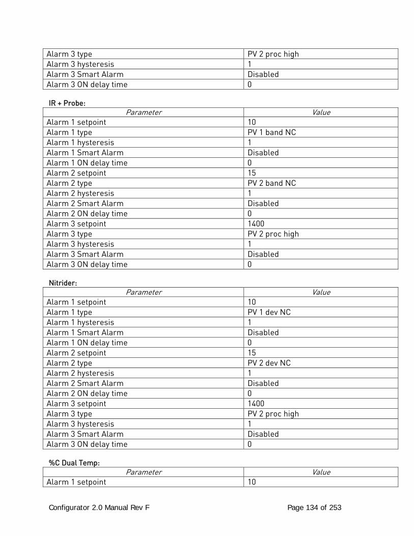
Configurator 2.0 Manual Rev F Page 134 of 253
Alarm 3 type PV 2 proc high Alarm 3 hysteresis 1 Alarm 3 Smart Alarm Disabled Alarm 3 ON delay time 0 IR + Probe:
Parameter Value Alarm 1 setpoint 10 Alarm 1 type PV 1 band NC Alarm 1 hysteresis 1 Alarm 1 Smart Alarm Disabled Alarm 1 ON delay time 0 Alarm 2 setpoint 15 Alarm 2 type PV 2 band NC Alarm 2 hysteresis 1 Alarm 2 Smart Alarm Disabled Alarm 2 ON delay time 0 Alarm 3 setpoint 1400 Alarm 3 type PV 2 proc high Alarm 3 hysteresis 1 Alarm 3 Smart Alarm Disabled Alarm 3 ON delay time 0 Nitrider:
Parameter Value Alarm 1 setpoint 10 Alarm 1 type PV 1 dev NC Alarm 1 hysteresis 1 Alarm 1 Smart Alarm Disabled Alarm 1 ON delay time 0 Alarm 2 setpoint 15 Alarm 2 type PV 2 dev NC Alarm 2 hysteresis 1 Alarm 2 Smart Alarm Disabled Alarm 2 ON delay time 0 Alarm 3 setpoint 1400 Alarm 3 type PV 2 proc high Alarm 3 hysteresis 1 Alarm 3 Smart Alarm Disabled Alarm 3 ON delay time 0 %C Dual Temp:
Parameter Value Alarm 1 setpoint 10
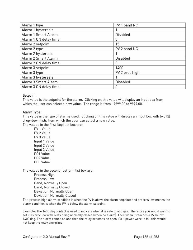
Configurator 2.0 Manual Rev F Page 135 of 253
Alarm 1 type PV 1 band NC Alarm 1 hysteresis 1 Alarm 1 Smart Alarm Disabled Alarm 1 ON delay time 0 Alarm 2 setpoint 15 Alarm 2 type PV 2 band NC Alarm 2 hysteresis 1 Alarm 2 Smart Alarm Disabled Alarm 2 ON delay time 0 Alarm 3 setpoint 1400 Alarm 3 type PV 2 proc high Alarm 3 hysteresis 1 Alarm 3 Smart Alarm Disabled Alarm 3 ON delay time 0 Setpoint: This value is the setpoint for the alarm. Clicking on this value will display an input box from which the user can select a new value. The range is from –9999.00 to 9999.00. Alarm Type: This value is the type of alarms used. Clicking on this value will display an input box with two (2) drop-down lists from which the user can select a new value. The values in the first (top) list box are:
PV 1 Value PV 2 Value PV 3 Value Input 1 Value Input 2 Value Input 3 Value PO1 Value PO2 Value PO3 Value The values in the second (bottom) list box are: Process High Process Low Band, Normally Open Band, Normally Closed Deviation, Normally Open Deviation, Normally Closed The process high alarm condition is when the PV is above the alarm setpoint; and process low means the alarm condition is when the PV is below the alarm setpoint. Example: The 1400 deg contact is used to indicate when it is safe to add gas. Therefore you would want to set it as proc low with relay being normally closed (when no alarm). Then when it reaches a PV below 1400 deg. The alarm comes on and then the relay becomes an open. So if power were to fail this would not keep the relay energized.
Configurator 2.0 Manual Rev F Page 136 of 253
Hysteresis: This value is the Hysteresis value. The Hysteresis is a set number that works with the alarm to help control a motor or pump longer to reach a set amount to come back into band before it will shut off motor or pump. Example: Using quench oil as an example, suppose the SP is 200 ◦F. The alarm is set as a deviation of +10 ◦F. At 210 ◦F, the alarm is active and the pump will run to cool the oil. With a hysteresis of 8 ◦F, the alarm and pump will turn off at 202 ◦F. It will turn back on when it is 10 ◦F above setpoint. If the setpoint is still 200 ◦F, then at 210 ◦F, it will turn on again. Clicking on this value will display an input box from which the user can select a new value. The range is from 0 to 9999. Smart Alarm: This value is a display of the Smart Alarm status. A smart alarm is an alarm that works with a Process Variable (PV), and, when enabled, it will not be active until the PV is within band of the setpoint. The alarm sounding - if active - will be disabled until within the SP band. When it is in band, the alarm will go active unless on delay time is set. Example: If the SP is 1700 and the band is 10 degrees the alarm will not be active until the PV reaches 1690. The value can be either disabled or enabled. ON Delay Time: This value is the ON Delay Time timer. If the timer is utilized, the alarm will not be active until the PV goes in band and activates the Smart alarm and then out of band and the timer has timed out (this is in seconds). Example: If you select 30, the output will not energize until 30 seconds after the alarm is active. Clicking on this value will display an input box from which the user can select a new value. The range is from 0 to 9999.
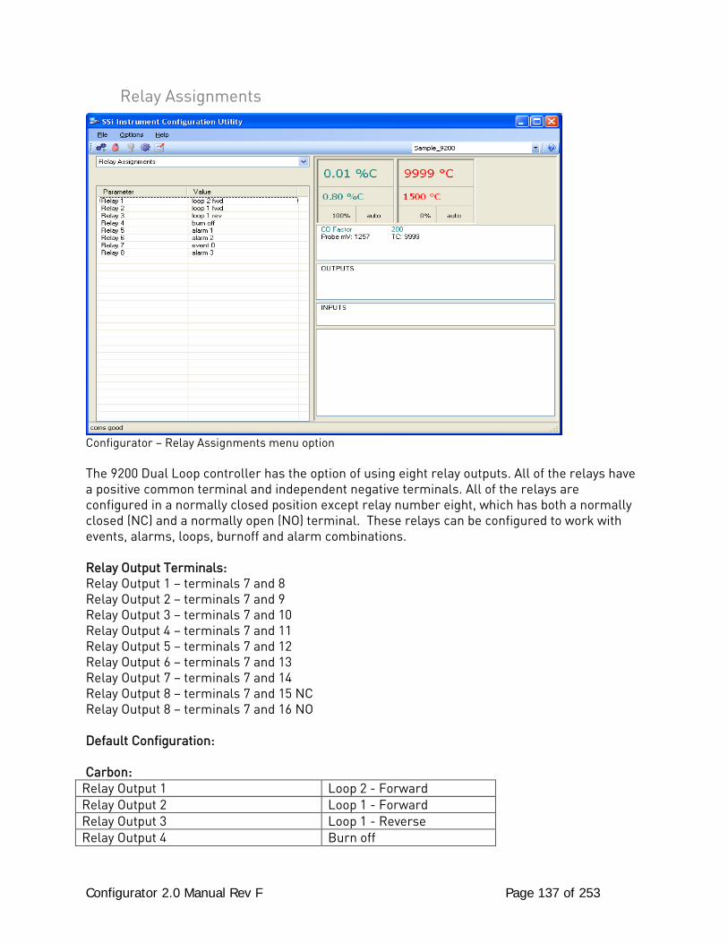
Configurator 2.0 Manual Rev F Page 137 of 253
Relay Assignments
Configurator – Relay Assignments menu option The 9200 Dual Loop controller has the option of using eight relay outputs. All of the relays have a positive common terminal and independent negative terminals. All of the relays are configured in a normally closed position except relay number eight, which has both a normally closed (NC) and a normally open (NO) terminal. These relays can be configured to work with events, alarms, loops, burnoff and alarm combinations. Relay Output Terminals: Relay Output 1 – terminals 7 and 8 Relay Output 2 – terminals 7 and 9 Relay Output 3 – terminals 7 and 10 Relay Output 4 – terminals 7 and 11 Relay Output 5 – terminals 7 and 12 Relay Output 6 – terminals 7 and 13 Relay Output 7 – terminals 7 and 14 Relay Output 8 – terminals 7 and 15 NC Relay Output 8 – terminals 7 and 16 NO Default Configuration: Carbon:
Relay Output 1 Loop 2 - Forward Relay Output 2 Loop 1 - Forward Relay Output 3 Loop 1 - Reverse Relay Output 4 Burn off
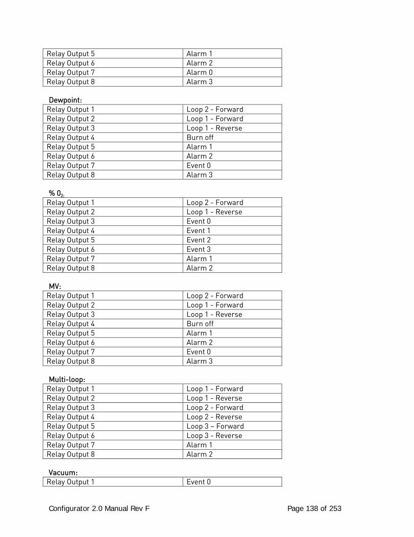
Configurator 2.0 Manual Rev F Page 138 of 253
Relay Output 5 Alarm 1 Relay Output 6 Alarm 2 Relay Output 7 Alarm 0 Relay Output 8 Alarm 3 Dewpoint:
Relay Output 1 Loop 2 - Forward Relay Output 2 Loop 1 - Forward Relay Output 3 Loop 1 - Reverse Relay Output 4 Burn off Relay Output 5 Alarm 1 Relay Output 6 Alarm 2 Relay Output 7 Event 0 Relay Output 8 Alarm 3 % 02:
Relay Output 1 Loop 2 - Forward Relay Output 2 Loop 1 - Reverse Relay Output 3 Event 0 Relay Output 4 Event 1 Relay Output 5 Event 2 Relay Output 6 Event 3 Relay Output 7 Alarm 1 Relay Output 8 Alarm 2 MV:
Relay Output 1 Loop 2 - Forward Relay Output 2 Loop 1 - Forward Relay Output 3 Loop 1 - Reverse Relay Output 4 Burn off Relay Output 5 Alarm 1 Relay Output 6 Alarm 2 Relay Output 7 Event 0 Relay Output 8 Alarm 3 Multi-loop:
Relay Output 1 Loop 1 - Forward Relay Output 2 Loop 1 - Reverse Relay Output 3 Loop 2 - Forward Relay Output 4 Loop 2 - Reverse Relay Output 5 Loop 3 – Forward Relay Output 6 Loop 3 - Reverse Relay Output 7 Alarm 1 Relay Output 8 Alarm 2 Vacuum:
Relay Output 1 Event 0
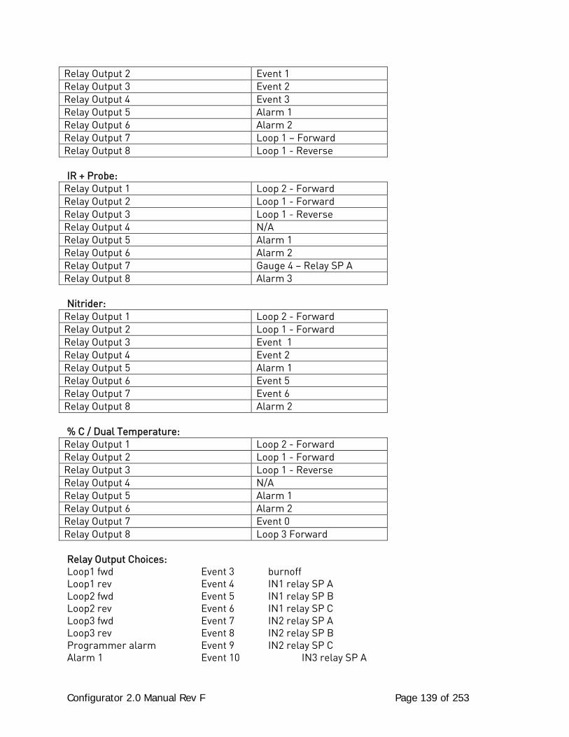
Configurator 2.0 Manual Rev F Page 139 of 253
Relay Output 2 Event 1 Relay Output 3 Event 2 Relay Output 4 Event 3 Relay Output 5 Alarm 1 Relay Output 6 Alarm 2 Relay Output 7 Loop 1 – Forward Relay Output 8 Loop 1 - Reverse IR + Probe:
Relay Output 1 Loop 2 - Forward Relay Output 2 Loop 1 - Forward Relay Output 3 Loop 1 - Reverse Relay Output 4 N/A Relay Output 5 Alarm 1 Relay Output 6 Alarm 2 Relay Output 7 Gauge 4 – Relay SP A Relay Output 8 Alarm 3 Nitrider:
Relay Output 1 Loop 2 - Forward Relay Output 2 Loop 1 - Forward Relay Output 3 Event 1 Relay Output 4 Event 2 Relay Output 5 Alarm 1 Relay Output 6 Event 5 Relay Output 7 Event 6 Relay Output 8 Alarm 2 % C / Dual Temperature:
Relay Output 1 Loop 2 - Forward Relay Output 2 Loop 1 - Forward Relay Output 3 Loop 1 - Reverse Relay Output 4 N/A Relay Output 5 Alarm 1 Relay Output 6 Alarm 2 Relay Output 7 Event 0 Relay Output 8 Loop 3 Forward Relay Output Choices: Loop1 fwd Event 3 burnoff Loop1 rev Event 4 IN1 relay SP A Loop2 fwd Event 5 IN1 relay SP B Loop2 rev Event 6 IN1 relay SP C Loop3 fwd Event 7 IN2 relay SP A Loop3 rev Event 8 IN2 relay SP B Programmer alarm Event 9 IN2 relay SP C Alarm 1 Event 10 IN3 relay SP A
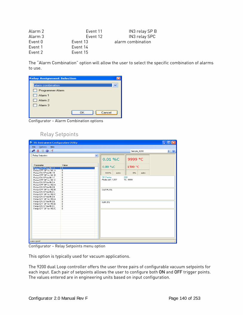
Configurator 2.0 Manual Rev F Page 140 of 253
Alarm 2 Event 11 IN3 relay SP B Alarm 3 Event 12 IN3 relay SPC Event 0 Event 13 alarm combination Event 1 Event 14 Event 2 Event 15 The “Alarm Combination” option will allow the user to select the specific combination of alarms to use.
Configurator – Alarm Combination options
Relay Setpoints
Configurator – Relay Setpoints menu option This option is typically used for vacuum applications. The 9200 dual Loop controller offers the user three pairs of configurable vacuum setpoints for each input. Each pair of setpoints allows the user to configure both ON and OFF trigger points. The values entered are in engineering units based on input configuration.
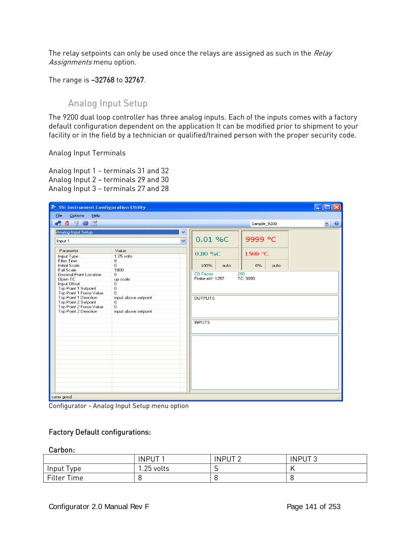
Configurator 2.0 Manual Rev F Page 141 of 253
The relay setpoints can only be used once the relays are assigned as such in the Relay Assignments menu option. The range is –32768 to 32767.
Analog Input Setup The 9200 dual loop controller has three analog inputs. Each of the inputs comes with a factory default configuration dependent on the application It can be modified prior to shipment to your facility or in the field by a technician or qualified/trained person with the proper security code. Analog Input Terminals Analog Input 1 – terminals 31 and 32 Analog Input 2 – terminals 29 and 30 Analog Input 3 – terminals 27 and 28
Configurator - Analog Input Setup menu option Factory Default configurations: Carbon: INPUT 1 INPUT 2 INPUT 3 Input Type 1.25 volts S K Filter Time 8 8 8
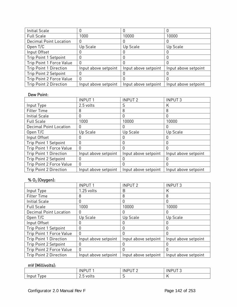
Configurator 2.0 Manual Rev F Page 142 of 253
Initial Scale 0 0 0 Full Scale 1000 10000 10000 Decimal Point Location 0 0 0 Open T/C Up Scale Up Scale Up Scale Input Offset 0 0 0 Trip Point 1 Setpoint 0 0 0 Trip Point 1 Force Value 0 0 0 Trip Point 1 Direction Input above setpoint Input above setpoint Input above setpoint Trip Point 2 Setpoint 0 0 0 Trip Point 2 Force Value 0 0 0 Trip Point 2 Direction Input above setpoint Input above setpoint Input above setpoint Dew Point:
INPUT 1 INPUT 2 INPUT 3 Input Type 2.5 volts S K Filter Time 8 8 8 Initial Scale 0 0 0 Full Scale 1000 10000 10000 Decimal Point Location 0 0 0 Open T/C Up Scale Up Scale Up Scale Input Offset 0 0 0 Trip Point 1 Setpoint 0 0 0 Trip Point 1 Force Value 0 0 0 Trip Point 1 Direction Input above setpoint Input above setpoint Input above setpoint Trip Point 2 Setpoint 0 0 0 Trip Point 2 Force Value 0 0 0 Trip Point 2 Direction Input above setpoint Input above setpoint Input above setpoint % O2 (Oxygen):
INPUT 1 INPUT 2 INPUT 3 Input Type 1.25 volts B K Filter Time 8 8 8 Initial Scale 0 0 0 Full Scale 1000 10000 10000 Decimal Point Location 0 0 0 Open T/C Up Scale Up Scale Up Scale Input Offset 0 0 0 Trip Point 1 Setpoint 0 0 0 Trip Point 1 Force Value 0 0 0 Trip Point 1 Direction Input above setpoint Input above setpoint Input above setpoint Trip Point 2 Setpoint 0 0 0 Trip Point 2 Force Value 0 0 0 Trip Point 2 Direction Input above setpoint Input above setpoint Input above setpoint mV (Millivolts):
INPUT 1 INPUT 2 INPUT 3 Input Type 2.5 volts S K
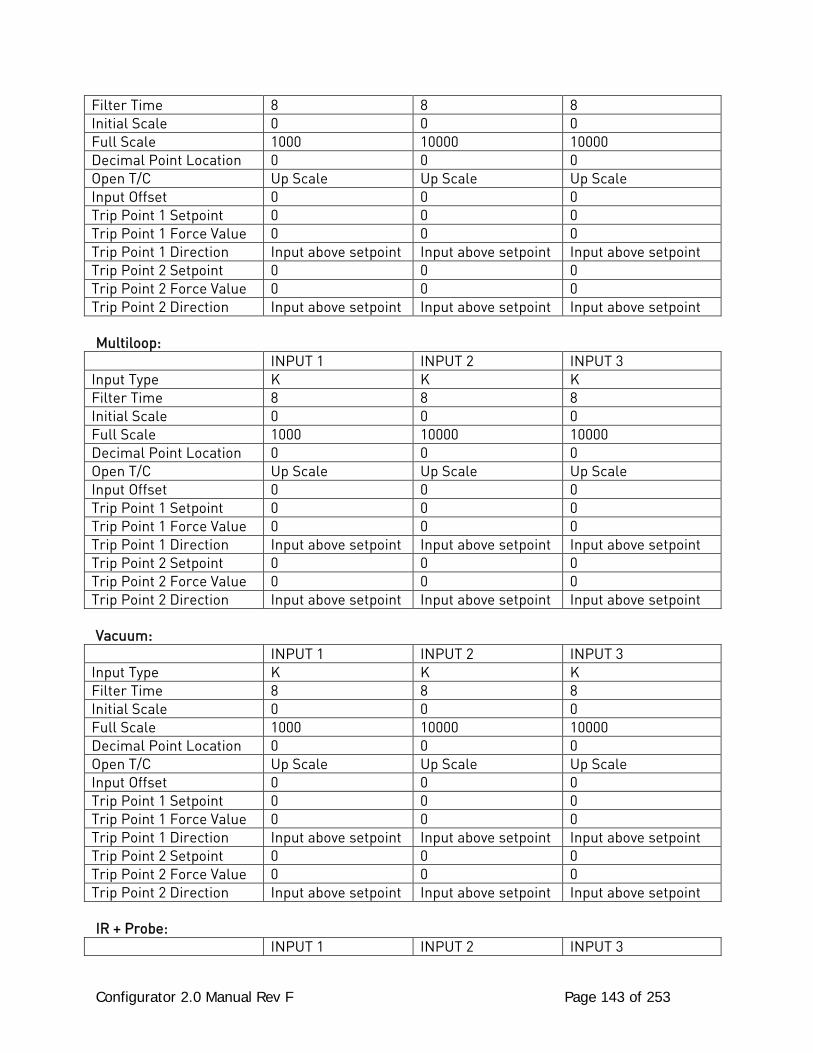
Configurator 2.0 Manual Rev F Page 143 of 253
Filter Time 8 8 8 Initial Scale 0 0 0 Full Scale 1000 10000 10000 Decimal Point Location 0 0 0 Open T/C Up Scale Up Scale Up Scale Input Offset 0 0 0 Trip Point 1 Setpoint 0 0 0 Trip Point 1 Force Value 0 0 0 Trip Point 1 Direction Input above setpoint Input above setpoint Input above setpoint Trip Point 2 Setpoint 0 0 0 Trip Point 2 Force Value 0 0 0 Trip Point 2 Direction Input above setpoint Input above setpoint Input above setpoint Multiloop:
INPUT 1 INPUT 2 INPUT 3 Input Type K K K Filter Time 8 8 8 Initial Scale 0 0 0 Full Scale 1000 10000 10000 Decimal Point Location 0 0 0 Open T/C Up Scale Up Scale Up Scale Input Offset 0 0 0 Trip Point 1 Setpoint 0 0 0 Trip Point 1 Force Value 0 0 0 Trip Point 1 Direction Input above setpoint Input above setpoint Input above setpoint Trip Point 2 Setpoint 0 0 0 Trip Point 2 Force Value 0 0 0 Trip Point 2 Direction Input above setpoint Input above setpoint Input above setpoint Vacuum:
INPUT 1 INPUT 2 INPUT 3 Input Type K K K Filter Time 8 8 8 Initial Scale 0 0 0 Full Scale 1000 10000 10000 Decimal Point Location 0 0 0 Open T/C Up Scale Up Scale Up Scale Input Offset 0 0 0 Trip Point 1 Setpoint 0 0 0 Trip Point 1 Force Value 0 0 0 Trip Point 1 Direction Input above setpoint Input above setpoint Input above setpoint Trip Point 2 Setpoint 0 0 0 Trip Point 2 Force Value 0 0 0 Trip Point 2 Direction Input above setpoint Input above setpoint Input above setpoint IR + Probe:
INPUT 1 INPUT 2 INPUT 3
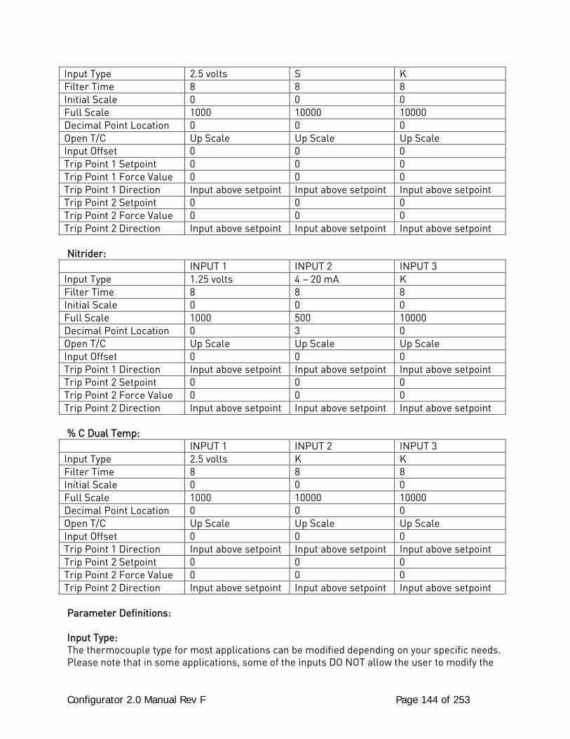
Configurator 2.0 Manual Rev F Page 144 of 253
Input Type 2.5 volts S K Filter Time 8 8 8 Initial Scale 0 0 0 Full Scale 1000 10000 10000 Decimal Point Location 0 0 0 Open T/C Up Scale Up Scale Up Scale Input Offset 0 0 0 Trip Point 1 Setpoint 0 0 0 Trip Point 1 Force Value 0 0 0 Trip Point 1 Direction Input above setpoint Input above setpoint Input above setpoint Trip Point 2 Setpoint 0 0 0 Trip Point 2 Force Value 0 0 0 Trip Point 2 Direction Input above setpoint Input above setpoint Input above setpoint Nitrider:
INPUT 1 INPUT 2 INPUT 3 Input Type 1.25 volts 4 – 20 mA K Filter Time 8 8 8 Initial Scale 0 0 0 Full Scale 1000 500 10000 Decimal Point Location 0 3 0 Open T/C Up Scale Up Scale Up Scale Input Offset 0 0 0 Trip Point 1 Direction Input above setpoint Input above setpoint Input above setpoint Trip Point 2 Setpoint 0 0 0 Trip Point 2 Force Value 0 0 0 Trip Point 2 Direction Input above setpoint Input above setpoint Input above setpoint % C Dual Temp:
INPUT 1 INPUT 2 INPUT 3 Input Type 2.5 volts K K Filter Time 8 8 8 Initial Scale 0 0 0 Full Scale 1000 10000 10000 Decimal Point Location 0 0 0 Open T/C Up Scale Up Scale Up Scale Input Offset 0 0 0 Trip Point 1 Direction Input above setpoint Input above setpoint Input above setpoint Trip Point 2 Setpoint 0 0 0 Trip Point 2 Force Value 0 0 0 Trip Point 2 Direction Input above setpoint Input above setpoint Input above setpoint Parameter Definitions: Input Type: The thermocouple type for most applications can be modified depending on your specific needs. Please note that in some applications, some of the inputs DO NOT allow the user to modify the
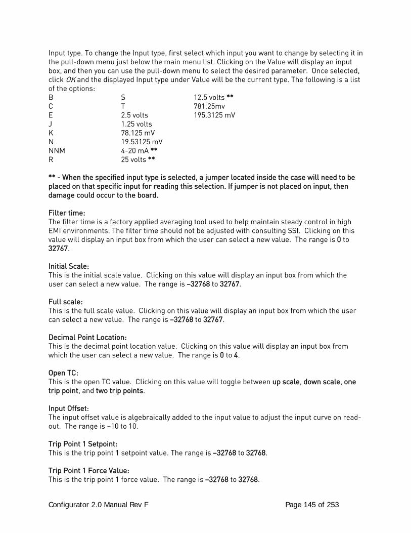
Configurator 2.0 Manual Rev F Page 145 of 253
Input type. To change the Input type, first select which input you want to change by selecting it in the pull-down menu just below the main menu list. Clicking on the Value will display an input box, and then you can use the pull-down menu to select the desired parameter. Once selected, click OK and the displayed Input type under Value will be the current type. The following is a list of the options: B S 12.5 volts ** C T 781.25mv E 2.5 volts 195.3125 mV J 1.25 volts K 78.125 mV N 19.53125 mV NNM 4-20 mA ** R 25 volts ** ** - When the specified input type is selected, a jumper located inside the case will need to be placed on that specific input for reading this selection. If jumper is not placed on input, then damage could occur to the board. Filter time: The filter time is a factory applied averaging tool used to help maintain steady control in high EMI environments. The filter time should not be adjusted with consulting SSI. Clicking on this value will display an input box from which the user can select a new value. The range is 0 to 32767. Initial Scale: This is the initial scale value. Clicking on this value will display an input box from which the user can select a new value. The range is –32768 to 32767. Full scale: This is the full scale value. Clicking on this value will display an input box from which the user can select a new value. The range is –32768 to 32767. Decimal Point Location: This is the decimal point location value. Clicking on this value will display an input box from which the user can select a new value. The range is 0 to 4. Open TC: This is the open TC value. Clicking on this value will toggle between up scale, down scale, one trip point, and two trip points. Input Offset: The input offset value is algebraically added to the input value to adjust the input curve on read-out. The range is –10 to 10. Trip Point 1 Setpoint: This is the trip point 1 setpoint value. The range is –32768 to 32768. Trip Point 1 Force Value: This is the trip point 1 force value. The range is –32768 to 32768.
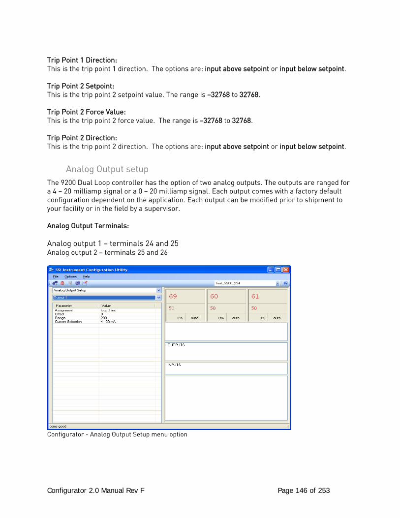
Configurator 2.0 Manual Rev F Page 146 of 253
Trip Point 1 Direction: This is the trip point 1 direction. The options are: input above setpoint or input below setpoint. Trip Point 2 Setpoint: This is the trip point 2 setpoint value. The range is –32768 to 32768. Trip Point 2 Force Value: This is the trip point 2 force value. The range is –32768 to 32768. Trip Point 2 Direction: This is the trip point 2 direction. The options are: input above setpoint or input below setpoint.
Analog Output setup The 9200 Dual Loop controller has the option of two analog outputs. The outputs are ranged for a 4 – 20 milliamp signal or a 0 – 20 milliamp signal. Each output comes with a factory default configuration dependent on the application. Each output can be modified prior to shipment to your facility or in the field by a supervisor. Analog Output Terminals: Analog output 1 – terminals 24 and 25 Analog output 2 – terminals 25 and 26
Configurator - Analog Output Setup menu option
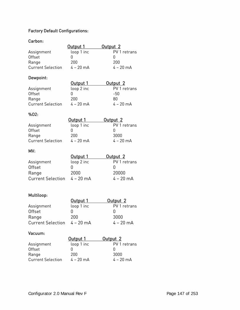
Configurator 2.0 Manual Rev F Page 147 of 253
Factory Default Configurations: Carbon: Output 1 Output 2 Assignment loop 1 inc PV 1 retrans Offset 0 0 Range 200 200 Current Selection 4 – 20 mA 4 – 20 mA Dewpoint: Output 1 Output 2 Assignment loop 2 inc PV 1 retrans Offset 0 -50 Range 200 80 Current Selection 4 – 20 mA 4 – 20 mA %O2: Output 1 Output 2 Assignment loop 1 inc PV 1 retrans Offset 0 0 Range 200 3000 Current Selection 4 – 20 mA 4 – 20 mA MV:
Output 1 Output 2 Assignment loop 2 inc PV 1 retrans Offset 0 0 Range 2000 20000 Current Selection 4 – 20 mA 4 – 20 mA
Multiloop: Output 1 Output 2 Assignment loop 1 inc PV 1 retrans Offset 0 0 Range 200 3000 Current Selection 4 – 20 mA 4 – 20 mA Vacuum: Output 1 Output 2 Assignment loop 1 inc PV 1 retrans Offset 0 0 Range 200 3000 Current Selection 4 – 20 mA 4 – 20 mA
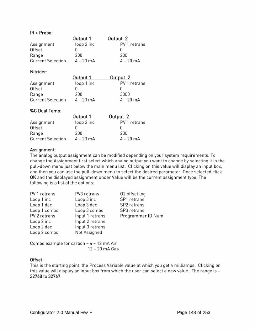
Configurator 2.0 Manual Rev F Page 148 of 253
IR + Probe: Output 1 Output 2 Assignment loop 2 inc PV 1 retrans Offset 0 0 Range 200 200 Current Selection 4 – 20 mA 4 – 20 mA Nitrider: Output 1 Output 2 Assignment loop 1 inc PV 1 retrans Offset 0 0 Range 200 3000 Current Selection 4 – 20 mA 4 – 20 mA %C Dual Temp: Output 1 Output 2 Assignment loop 2 inc PV 1 retrans Offset 0 0 Range 200 200 Current Selection 4 – 20 mA 4 – 20 mA Assignment: The analog output assignment can be modified depending on your system requirements. To change the Assignment first select which analog output you want to change by selecting it in the pull-down menu just below the main menu list. Clicking on this value will display an input box, and then you can use the pull-down menu to select the desired parameter. Once selected click OK and the displayed assignment under Value will be the current assignment type. The following is a list of the options: PV 1 retrans PV3 retrans O2 offset log Loop 1 inc Loop 3 inc SP1 retrans Loop 1 dec Loop 3 dec SP2 retrans Loop 1 combo Loop 3 combo SP3 retrans PV 2 retrans Input 1 retrans Programmer ID Num Loop 2 inc Input 2 retrans Loop 2 dec Input 3 retrans Loop 2 combo Not Assigned Combo example for carbon – 4 – 12 mA Air 12 – 20 mA Gas Offset: This is the starting point, the Process Variable value at which you get 4 milliamps. Clicking on this value will display an input box from which the user can select a new value. The range is –32768 to 32767.
Configurator 2.0 Manual Rev F Page 149 of 253
Range: This is a Process Variable value between 4 and 20 milliamps. Clicking on this value will display an input box from which the user can select a new value. The range is –32768 to 32767. Note: The range, although not displayed with a decimal point, contains a decimal point that is dependent on the process variable selected. For example, If the offset is 20 mV for 4 mA, and you want 100 mV to be 20 mA, then your range should be 80. If the process variable is temperature, then the range will be 80, since temperature PVs do not have a decimal. If the PV is % Carbon, then the range will need to include the two decimal points for % Carbon. So, a range of 80 will be entered as 8000. See below for more examples. Current Selection: Provides the option of 4-20 mA or 0-20 mA control. Clicking on this value will display an input box with a drop-down list from which the user can select either of the two values listed above. Offset and Range when assigned to a control loop: Inc -- 0 = 4mA, 100 = 20mA Dec -- 0 = 4mA, -100 = 20mA Example: if 4 – 20 mA = 800 mV - 1200 mV Offset = 800 (starting point) Range = 400 Example: if 4 – 20 mA = 800 mV - 1200 mV and PV is Temperature Offset = 800 (starting point) Range = 400 Example: if 4 – 20 mA = 800 mV - 1200 mV and PV is % Carbon Offset = 800 (starting point) Range = 40000 (400.00)
Passcode and Alarm There are four levels of menus in the 9200 Dual loop controller - Operator, Supervisor, Administrator, and SSi Special.
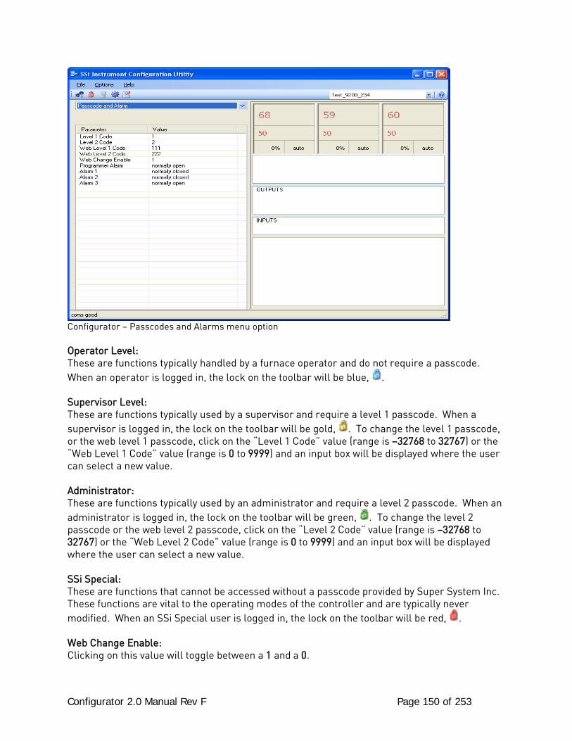
Configurator 2.0 Manual Rev F Page 150 of 253
Configurator – Passcodes and Alarms menu option Operator Level: These are functions typically handled by a furnace operator and do not require a passcode. When an operator is logged in, the lock on the toolbar will be blue, . Supervisor Level: These are functions typically used by a supervisor and require a level 1 passcode. When a supervisor is logged in, the lock on the toolbar will be gold, . To change the level 1 passcode, or the web level 1 passcode, click on the “Level 1 Code” value (range is –32768 to 32767) or the “Web Level 1 Code” value (range is 0 to 9999) and an input box will be displayed where the user can select a new value. Administrator: These are functions typically used by an administrator and require a level 2 passcode. When an administrator is logged in, the lock on the toolbar will be green, . To change the level 2 passcode or the web level 2 passcode, click on the “Level 2 Code” value (range is –32768 to 32767) or the “Web Level 2 Code” value (range is 0 to 9999) and an input box will be displayed where the user can select a new value. SSi Special: These are functions that cannot be accessed without a passcode provided by Super System Inc. These functions are vital to the operating modes of the controller and are typically never modified. When an SSi Special user is logged in, the lock on the toolbar will be red, . Web Change Enable: Clicking on this value will toggle between a 1 and a 0.
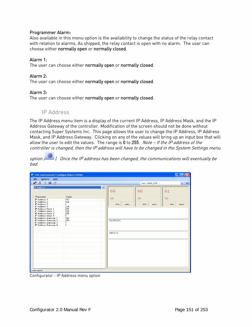
Configurator 2.0 Manual Rev F Page 151 of 253
Programmer Alarm: Also available in this menu option is the availability to change the status of the relay contact with relation to alarms. As shipped, the relay contact is open with no alarm. The user can choose either normally open or normally closed. Alarm 1: The user can choose either normally open or normally closed. Alarm 2: The user can choose either normally open or normally closed. Alarm 3: The user can choose either normally open or normally closed.
IP Address The IP Address menu item is a display of the current IP Address, IP Address Mask, and the IP Address Gateway of the controller. Modification of the screen should not be done without contacting Super Systems Inc. This page allows the user to change the IP Address, IP Address Mask, and IP Address Gateway. Clicking on any of the values will bring up an input box that will allow the user to edit the values. The range is 0 to 255. Note – If the IP address of the controller is changed, then the IP address will have to be changed in the System Settings menu
option ( ). Once the IP address has been changed, the communications will eventually be bad.
Configurator - IP Address menu option
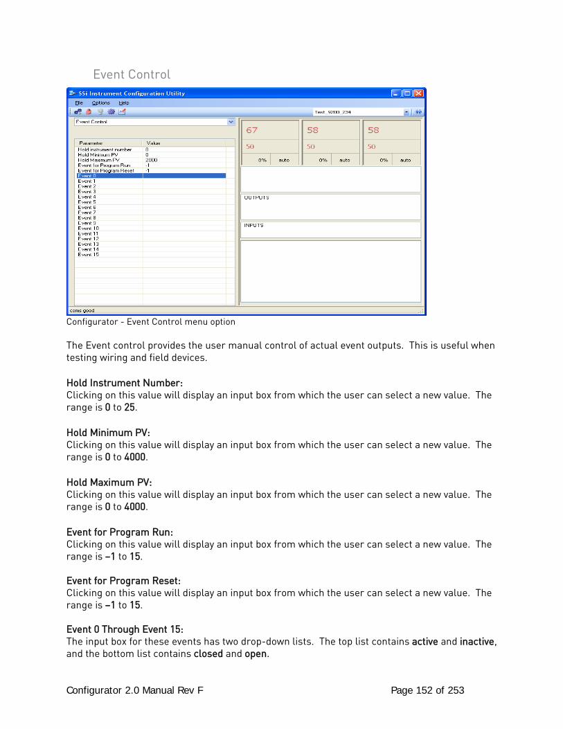
Configurator 2.0 Manual Rev F Page 152 of 253
Event Control
Configurator - Event Control menu option The Event control provides the user manual control of actual event outputs. This is useful when testing wiring and field devices. Hold Instrument Number: Clicking on this value will display an input box from which the user can select a new value. The range is 0 to 25. Hold Minimum PV: Clicking on this value will display an input box from which the user can select a new value. The range is 0 to 4000. Hold Maximum PV: Clicking on this value will display an input box from which the user can select a new value. The range is 0 to 4000. Event for Program Run: Clicking on this value will display an input box from which the user can select a new value. The range is –1 to 15. Event for Program Reset: Clicking on this value will display an input box from which the user can select a new value. The range is –1 to 15. Event 0 Through Event 15: The input box for these events has two drop-down lists. The top list contains active and inactive, and the bottom list contains closed and open.
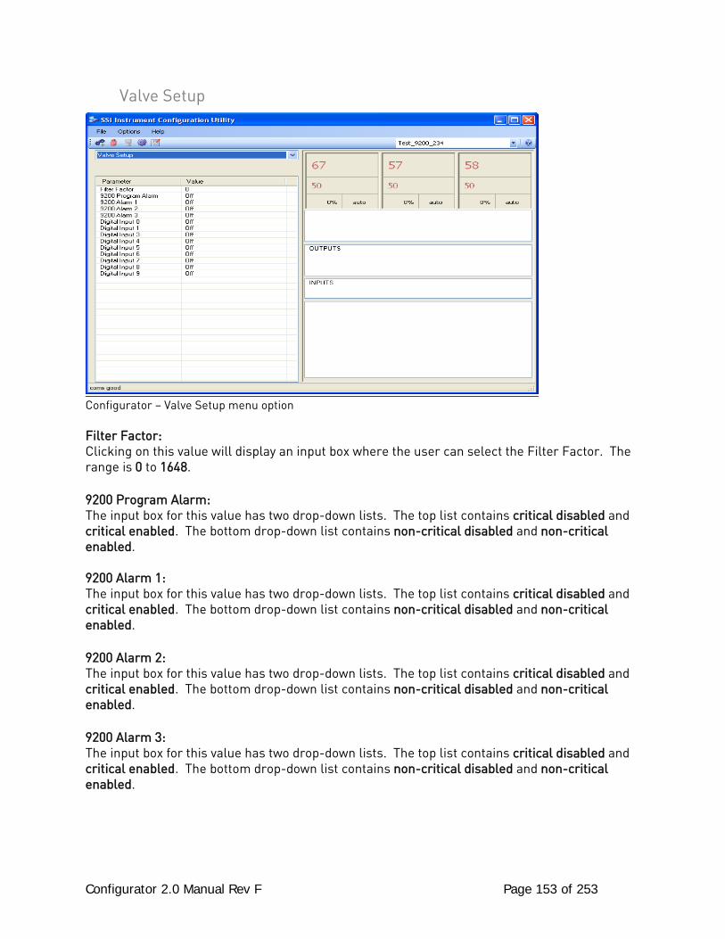
Configurator 2.0 Manual Rev F Page 153 of 253
Valve Setup
Configurator – Valve Setup menu option Filter Factor: Clicking on this value will display an input box where the user can select the Filter Factor. The range is 0 to 1648. 9200 Program Alarm: The input box for this value has two drop-down lists. The top list contains critical disabled and critical enabled. The bottom drop-down list contains non-critical disabled and non-critical enabled. 9200 Alarm 1: The input box for this value has two drop-down lists. The top list contains critical disabled and critical enabled. The bottom drop-down list contains non-critical disabled and non-critical enabled. 9200 Alarm 2: The input box for this value has two drop-down lists. The top list contains critical disabled and critical enabled. The bottom drop-down list contains non-critical disabled and non-critical enabled. 9200 Alarm 3: The input box for this value has two drop-down lists. The top list contains critical disabled and critical enabled. The bottom drop-down list contains non-critical disabled and non-critical enabled.
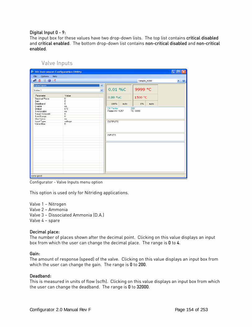
Configurator 2.0 Manual Rev F Page 154 of 253
Digital Input 0 - 9: The input box for these values have two drop-down lists. The top list contains critical disabled and critical enabled. The bottom drop-down list contains non-critical disabled and non-critical enabled.
Valve Inputs
Configurator - Valve Inputs menu option This option is used only for Nitriding applications. Valve 1 – Nitrogen Valve 2 – Ammonia Valve 3 – Dissociated Ammonia (D.A.) Valve 4 – spare Decimal place: The number of places shown after the decimal point. Clicking on this value displays an input box from which the user can change the decimal place. The range is 0 to 4. Gain: The amount of response (speed) of the valve. Clicking on this value displays an input box from which the user can change the gain. The range is 0 to 200. Deadband: This is measured in units of flow (scfh). Clicking on this value displays an input box from which the user can change the deadband. The range is 0 to 32000.
Configurator 2.0 Manual Rev F Page 155 of 253
Enable: Enable allows the user to manually turn the valve on or off. The options are Yes or No. Output: This is the measured output shown as a percentage, and it cannot be modified. Trim Enable: Trim Enable allows the user to manually turn the trim on or off. The options are Yes or No. Target Setpoint: This is measured in units of flow (scfh). Clicking on the value will display an input box from which the user can select a new setpoint. The range is 0 to 4000. Trim Range: The allowable specified range of control with the trim enabled - typically set in the program. Clicking on this value will display an input box from which the user can select a new Trim Range. The range is 0 to 10000. Use Curve: This option manually turns on or off the custom curve entered in the Curve Entry menu option. The options are Yes or No. Input Type: Clicking on this value will display a drop down menu with the following choices: voltage mA / 124 ohm mA / 249 ohm mA / 499 ohm Valve Max: This is the maximum valve range in units. Clicking on this value displays an input box from which the user can select a new maximum value. The range is 100 to 30000.
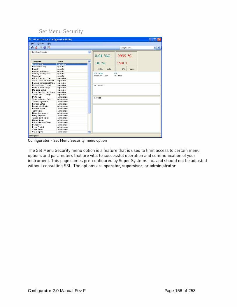
Configurator 2.0 Manual Rev F Page 156 of 253
Set Menu Security
Configurator - Set Menu Security menu option The Set Menu Security menu option is a feature that is used to limit access to certain menu options and parameters that are vital to successful operation and communication of your instrument. This page comes pre-configured by Super Systems Inc. and should not be adjusted without consulting SSI. The options are operator, supervisor, or administrator.
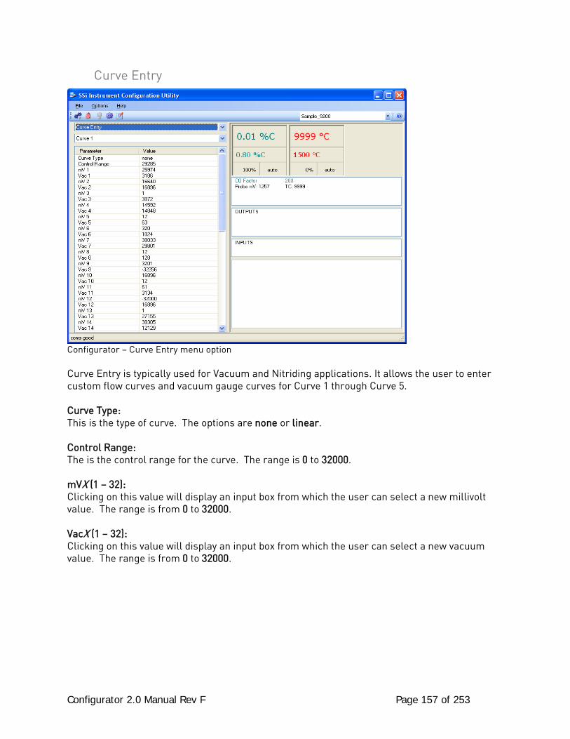
Configurator 2.0 Manual Rev F Page 157 of 253
Curve Entry
Configurator – Curve Entry menu option Curve Entry is typically used for Vacuum and Nitriding applications. It allows the user to enter custom flow curves and vacuum gauge curves for Curve 1 through Curve 5. Curve Type: This is the type of curve. The options are none or linear. Control Range: The is the control range for the curve. The range is 0 to 32000. mVX (1 – 32): Clicking on this value will display an input box from which the user can select a new millivolt value. The range is from 0 to 32000. VacX (1 – 32): Clicking on this value will display an input box from which the user can select a new vacuum value. The range is from 0 to 32000.
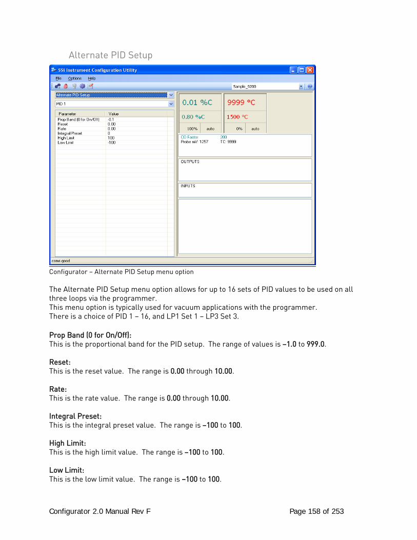
Configurator 2.0 Manual Rev F Page 158 of 253
Alternate PID Setup
Configurator – Alternate PID Setup menu option The Alternate PID Setup menu option allows for up to 16 sets of PID values to be used on all three loops via the programmer. This menu option is typically used for vacuum applications with the programmer. There is a choice of PID 1 – 16, and LP1 Set 1 – LP3 Set 3. Prop Band (0 for On/Off): This is the proportional band for the PID setup. The range of values is –1.0 to 999.0. Reset: This is the reset value. The range is 0.00 through 10.00. Rate: This is the rate value. The range is 0.00 through 10.00. Integral Preset: This is the integral preset value. The range is –100 to 100. High Limit: This is the high limit value. The range is –100 to 100. Low Limit: This is the low limit value. The range is –100 to 100.
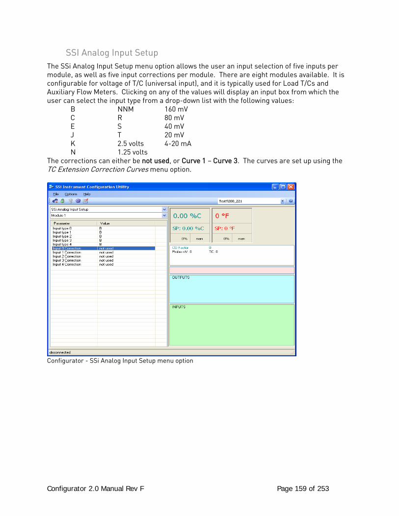
Configurator 2.0 Manual Rev F Page 159 of 253
SSI Analog Input Setup The SSi Analog Input Setup menu option allows the user an input selection of five inputs per module, as well as five input corrections per module. There are eight modules available. It is configurable for voltage of T/C (universal input), and it is typically used for Load T/Cs and Auxiliary Flow Meters. Clicking on any of the values will display an input box from which the user can select the input type from a drop-down list with the following values: B NNM 160 mV C R 80 mV E S 40 mV J T 20 mV K 2.5 volts 4-20 mA N 1.25 volts The corrections can either be not used, or Curve 1 – Curve 3. The curves are set up using the TC Extension Correction Curves menu option.
Configurator - SSi Analog Input Setup menu option
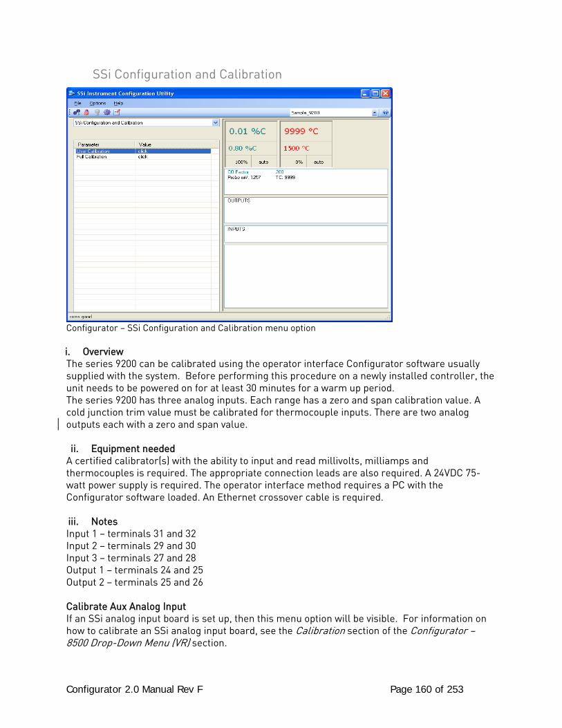
Configurator 2.0 Manual Rev F Page 160 of 253
SSi Configuration and Calibration
Configurator – SSi Configuration and Calibration menu option i. Overview The series 9200 can be calibrated using the operator interface Configurator software usually supplied with the system. Before performing this procedure on a newly installed controller, the unit needs to be powered on for at least 30 minutes for a warm up period. The series 9200 has three analog inputs. Each range has a zero and span calibration value. A cold junction trim value must be calibrated for thermocouple inputs. There are two analog outputs each with a zero and span value. ii. Equipment needed
A certified calibrator(s) with the ability to input and read millivolts, milliamps and thermocouples is required. The appropriate connection leads are also required. A 24VDC 75-watt power supply is required. The operator interface method requires a PC with the Configurator software loaded. An Ethernet crossover cable is required. iii. Notes Input 1 – terminals 31 and 32 Input 2 – terminals 29 and 30 Input 3 – terminals 27 and 28 Output 1 – terminals 24 and 25 Output 2 – terminals 25 and 26 Calibrate Aux Analog Input If an SSi analog input board is set up, then this menu option will be visible. For information on how to calibrate an SSi analog input board, see the Calibration section of the Configurator – 8500 Drop-Down Menu (VR) section.
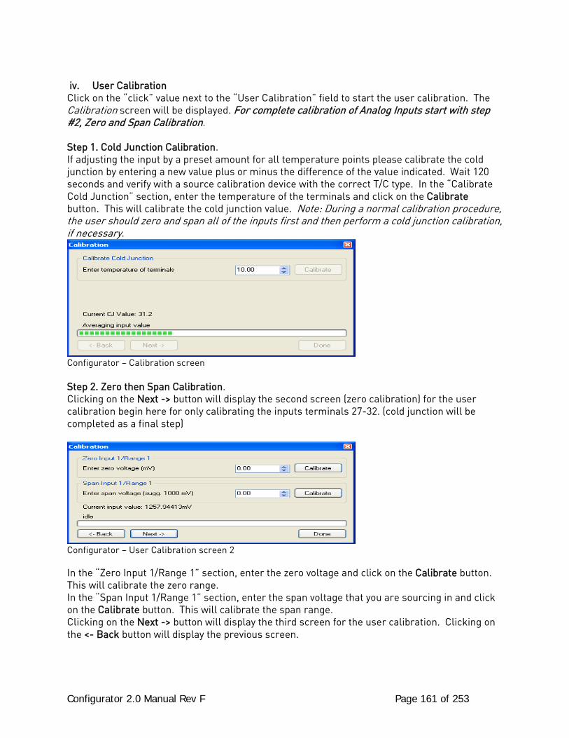
Configurator 2.0 Manual Rev F Page 161 of 253
iv. User Calibration
Click on the “click” value next to the “User Calibration” field to start the user calibration. The Calibration screen will be displayed. For complete calibration of Analog Inputs start with step #2, Zero and Span Calibration. Step 1. Cold Junction Calibration. If adjusting the input by a preset amount for all temperature points please calibrate the cold junction by entering a new value plus or minus the difference of the value indicated. Wait 120 seconds and verify with a source calibration device with the correct T/C type. In the “Calibrate Cold Junction” section, enter the temperature of the terminals and click on the Calibrate button. This will calibrate the cold junction value. Note: During a normal calibration procedure, the user should zero and span all of the inputs first and then perform a cold junction calibration, if necessary.
Configurator – Calibration screen Step 2. Zero then Span Calibration. Clicking on the Next -> button will display the second screen (zero calibration) for the user calibration begin here for only calibrating the inputs terminals 27-32. (cold junction will be completed as a final step)
Configurator – User Calibration screen 2 In the “Zero Input 1/Range 1” section, enter the zero voltage and click on the Calibrate button. This will calibrate the zero range. In the “Span Input 1/Range 1” section, enter the span voltage that you are sourcing in and click on the Calibrate button. This will calibrate the span range. Clicking on the Next -> button will display the third screen for the user calibration. Clicking on the <- Back button will display the previous screen.
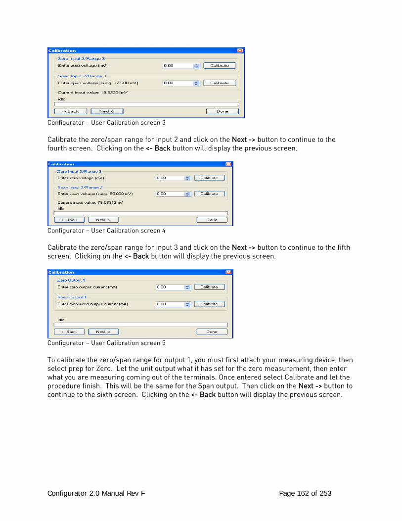
Configurator 2.0 Manual Rev F Page 162 of 253
Configurator – User Calibration screen 3 Calibrate the zero/span range for input 2 and click on the Next -> button to continue to the fourth screen. Clicking on the <- Back button will display the previous screen.
Configurator – User Calibration screen 4
Calibrate the zero/span range for input 3 and click on the Next -> button to continue to the fifth screen. Clicking on the <- Back button will display the previous screen.
Configurator – User Calibration screen 5 To calibrate the zero/span range for output 1, you must first attach your measuring device, then select prep for Zero. Let the unit output what it has set for the zero measurement, then enter what you are measuring coming out of the terminals. Once entered select Calibrate and let the procedure finish. This will be the same for the Span output. Then click on the Next -> button to continue to the sixth screen. Clicking on the <- Back button will display the previous screen.
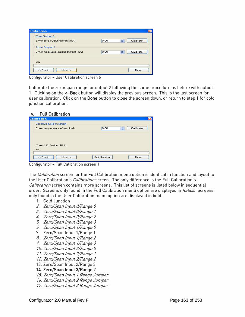
Configurator 2.0 Manual Rev F Page 163 of 253
Configurator – User Calibration screen 6 Calibrate the zero/span range for output 2 following the same procedure as before with output 1. Clicking on the <- Back button will display the previous screen. This is the last screen for user calibration. Click on the Done button to close the screen down, or return to step 1 for cold junction calibration.
v. Full Calibration
Configurator – Full Calibration screen 1 The Calibration screen for the Full Calibration menu option is identical in function and layout to the User Calibration’s Calibration screen. The only difference is the Full Calibration’s Calibration screen contains more screens. This list of screens is listed below in sequential order. Screens only found in the Full Calibration menu option are displayed in Italics. Screens only found in the User Calibration menu option are displayed in bold.
1. Cold Junction 2. Zero/Span Input 0/Range 0 3. Zero/Span Input 0/Range 1 4. Zero/Span Input 0/Range 2 5. Zero/Span Input 0/Range 3 6. Zero/Span Input 1/Range 0 7. Zero/Span Input 1/Range 1 8. Zero/Span Input 1/Range 2 9. Zero/Span Input 1/Range 3 10. Zero/Span Input 2/Range 0 11. Zero/Span Input 2/Range 1 12. Zero/Span Input 2/Range 2 13. Zero/Span Input 2/Range 3 14. Zero/Span Input 3/Range 2 15. Zero/Span Input 1 Range Jumper 16. Zero/Span Input 2 Range Jumper 17. Zero/Span Input 3 Range Jumper
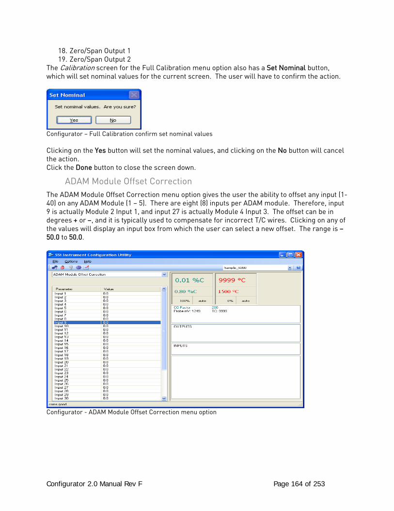
Configurator 2.0 Manual Rev F Page 164 of 253
18. Zero/Span Output 1 19. Zero/Span Output 2
The Calibration screen for the Full Calibration menu option also has a Set Nominal button, which will set nominal values for the current screen. The user will have to confirm the action.
Configurator – Full Calibration confirm set nominal values Clicking on the Yes button will set the nominal values, and clicking on the No button will cancel the action. Click the Done button to close the screen down.
ADAM Module Offset Correction The ADAM Module Offset Correction menu option gives the user the ability to offset any input (1-40) on any ADAM Module (1 – 5). There are eight (8) inputs per ADAM module. Therefore, input 9 is actually Module 2 Input 1, and input 27 is actually Module 4 Input 3. The offset can be in degrees + or –, and it is typically used to compensate for incorrect T/C wires. Clicking on any of the values will display an input box from which the user can select a new offset. The range is –50.0 to 50.0.
Configurator - ADAM Module Offset Correction menu option
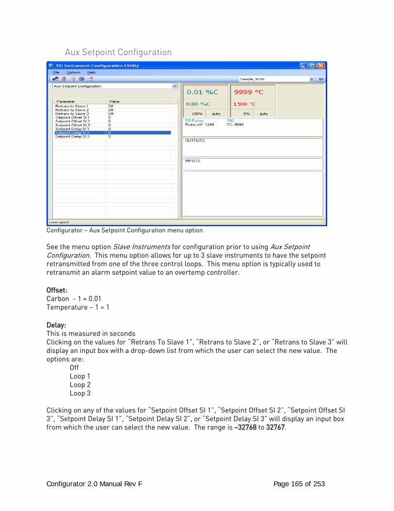
Configurator 2.0 Manual Rev F Page 165 of 253
Aux Setpoint Configuration
Configurator – Aux Setpoint Configuration menu option See the menu option Slave Instruments for configuration prior to using Aux Setpoint Configuration. This menu option allows for up to 3 slave instruments to have the setpoint retransmitted from one of the three control loops. This menu option is typically used to retransmit an alarm setpoint value to an overtemp controller. Offset: Carbon - 1 = 0.01 Temperature – 1 = 1 Delay: This is measured in seconds Clicking on the values for “Retrans To Slave 1”, “Retrans to Slave 2”, or “Retrans to Slave 3” will display an input box with a drop-down list from which the user can select the new value. The options are: Off Loop 1 Loop 2 Loop 3 Clicking on any of the values for “Setpoint Offset SI 1”, “Setpoint Offset SI 2”, “Setpoint Offset SI 3”, “Setpoint Delay SI 1”, “Setpoint Delay SI 2”, or “Setpoint Delay SI 3” will display an input box from which the user can select the new value. The range is –32768 to 32767.
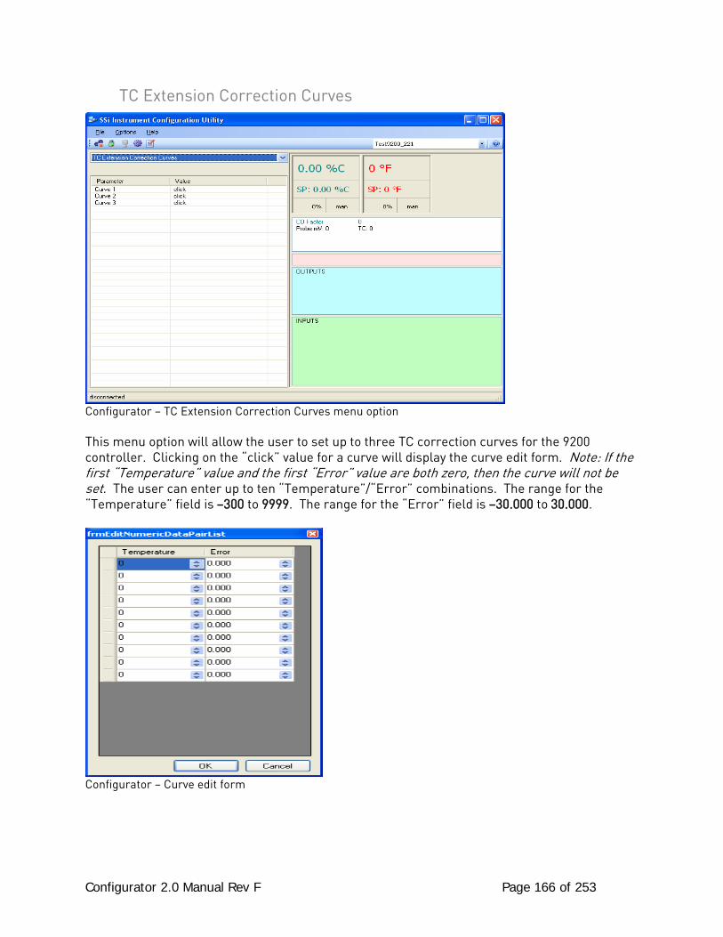
Configurator 2.0 Manual Rev F Page 166 of 253
TC Extension Correction Curves
Configurator – TC Extension Correction Curves menu option This menu option will allow the user to set up to three TC correction curves for the 9200 controller. Clicking on the “click” value for a curve will display the curve edit form. Note: If the first “Temperature” value and the first “Error” value are both zero, then the curve will not be set. The user can enter up to ten “Temperature”/“Error” combinations. The range for the “Temperature” field is –300 to 9999. The range for the “Error” field is –30.000 to 30.000.
Configurator – Curve edit form
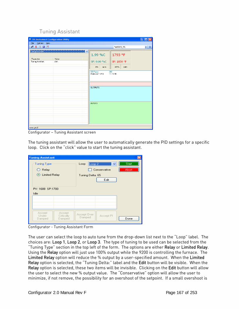
Configurator 2.0 Manual Rev F Page 167 of 253
Tuning Assistant
Configurator – Tuning Assistant screen The tuning assistant will allow the user to automatically generate the PID settings for a specific loop. Click on the “click” value to start the tuning assistant.
Configurator - Tuning Assistant Form The user can select the loop to auto tune from the drop-down list next to the “Loop” label. The choices are: Loop 1, Loop 2, or Loop 3. The type of tuning to be used can be selected from the “Tuning Type” section in the top left of the form. The options are either Relay or Limited Relay. Using the Relay option will just use 100% output while the 9200 is controlling the furnace. The Limited Relay option will reduce the % output by a user-specified amount. When the Limited Relay option is selected, the “Tuning Delta:” label and the Edit button will be visible. When the Relay option is selected, these two items will be invisible. Clicking on the Edit button will allow the user to select the new % output value. The “Conservative” option will allow the user to minimize, if not remove, the possibility for an overshoot of the setpoint. If a small overshoot is
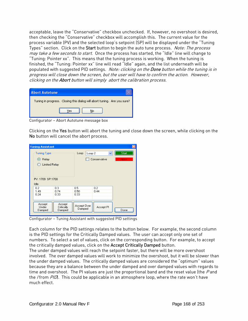
Configurator 2.0 Manual Rev F Page 168 of 253
acceptable, leave the “Conservative” checkbox unchecked. If, however, no overshoot is desired, then checking the “Conservative” checkbox will accomplish this. The current value for the process variable (PV) and the selected loop’s setpoint (SP) will be displayed under the “Tuning Types” section. Click on the Start button to begin the auto tune process. Note: The process may take a few seconds to start. Once the process has started, the “Idle” line will change to “Tuning: Pointer xx”. This means that the tuning process is working. When the tuning is finished, the “Tuning: Pointer xx” line will read “Idle” again, and the list underneath will be populated with suggested PID settings. Note: clicking on the Done button while the tuning is in progress will close down the screen, but the user will have to confirm the action. However, clicking on the Abort button will simply abort the calibration process.
Configurator – Abort Autotune message box Clicking on the Yes button will abort the tuning and close down the screen, while clicking on the No button will cancel the abort process.
Configurator – Tuning Assistant with suggested PID settings Each column for the PID settings relates to the button below. For example, the second column is the PID settings for the Critically Damped values. The user can accept only one set of numbers. To select a set of values, click on the corresponding button. For example, to accept the critically damped values, click on the Accept Critically Damped button. The under damped values will reach the setpoint faster, but there will be more overshoot involved. The over damped values will work to minimize the overshoot, but it will be slower than the under damped values. The critically damped values are considered the “optimum” values because they are a balance between the under damped and over damped values with regards to time and overshoot. The PI values are just the proportional band and the reset value (the P and the I from PID). This could be applicable in an atmosphere loop, where the rate won’t have much effect.

Configurator 2.0 Manual Rev F Page 169 of 253
Once a set of values has been accepted, the user can press the Done button to exit the screen. The accepted values can be viewed on the PID Loop Setup menu option. Note: Once the screen is closed out, the PID settings values will be lost. To populate these values again, another tuning routine will need to be run.
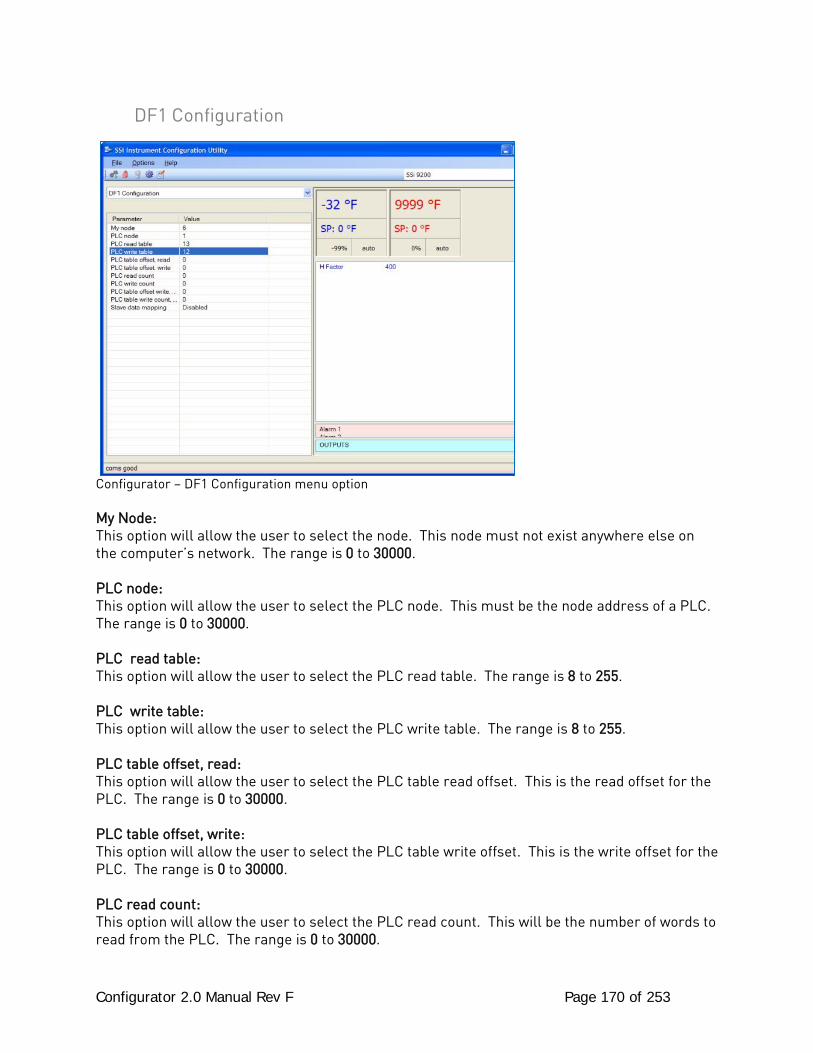
Configurator 2.0 Manual Rev F Page 170 of 253
DF1 Configuration
Configurator – DF1 Configuration menu option My Node: This option will allow the user to select the node. This node must not exist anywhere else on the computer’s network. The range is 0 to 30000. PLC node: This option will allow the user to select the PLC node. This must be the node address of a PLC. The range is 0 to 30000. PLC read table: This option will allow the user to select the PLC read table. The range is 8 to 255. PLC write table: This option will allow the user to select the PLC write table. The range is 8 to 255. PLC table offset, read: This option will allow the user to select the PLC table read offset. This is the read offset for the PLC. The range is 0 to 30000. PLC table offset, write: This option will allow the user to select the PLC table write offset. This is the write offset for the PLC. The range is 0 to 30000. PLC read count: This option will allow the user to select the PLC read count. This will be the number of words to read from the PLC. The range is 0 to 30000.

Configurator 2.0 Manual Rev F Page 171 of 253
PLC write count: This option will allow the user to select the PLC write count. This will be the number of words to write to the PLC. The range is 0 to 30000. PLC table offset write, extra: This option will allow the user to select the PLC table write offset extra. This is the extra write offset for the PLC. The range is 0 to 30000. PLC table write count, extra: This option will allow the user to select the PLC table write count extra. This will be the number of extra words to write to the PLC. The range is 0 to 30000. Slave data mapping: This option will allow the user to select the object to map the PLC bitmap to. The user can select: Disabled, Slave Mapping Enabled, Loop Mapping Enabled, or Slave & Loop Mapping Enabled.
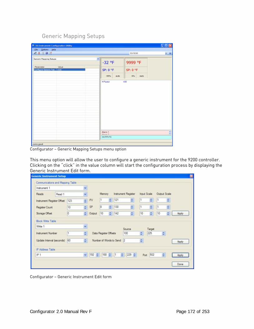
Configurator 2.0 Manual Rev F Page 172 of 253
Generic Mapping Setups
Configurator – Generic Mapping Setups menu option This menu option will allow the user to configure a generic instrument for the 9200 controller. Clicking on the “click” in the value column will start the configuration process by displaying the Generic Instrument Edit form.
Configurator – Generic Instrument Edit form
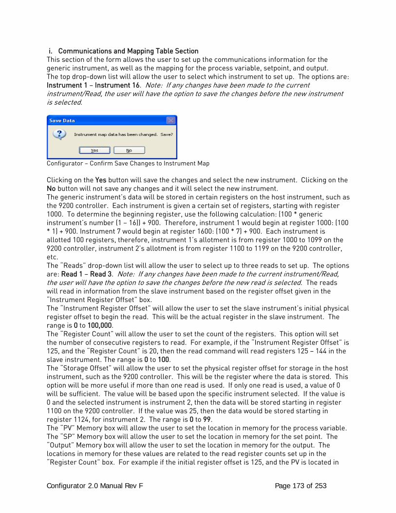
Configurator 2.0 Manual Rev F Page 173 of 253
i. Communications and Mapping Table Section This section of the form allows the user to set up the communications information for the generic instrument, as well as the mapping for the process variable, setpoint, and output. The top drop-down list will allow the user to select which instrument to set up. The options are: Instrument 1 – Instrument 16. Note: If any changes have been made to the current instrument/Read, the user will have the option to save the changes before the new instrument is selected.
Configurator – Confirm Save Changes to Instrument Map Clicking on the Yes button will save the changes and select the new instrument. Clicking on the No button will not save any changes and it will select the new instrument. The generic instrument’s data will be stored in certain registers on the host instrument, such as the 9200 controller. Each instrument is given a certain set of registers, starting with register 1000. To determine the beginning register, use the following calculation: (100 * generic instrument’s number (1 – 16)) + 900. Therefore, instrument 1 would begin at register 1000: (100 * 1) + 900. Instrument 7 would begin at register 1600: (100 * 7) + 900. Each instrument is allotted 100 registers, therefore, instrument 1’s allotment is from register 1000 to 1099 on the 9200 controller, instrument 2’s allotment is from register 1100 to 1199 on the 9200 controller, etc. The “Reads” drop-down list will allow the user to select up to three reads to set up. The options are: Read 1 – Read 3. Note: If any changes have been made to the current instrument/Read, the user will have the option to save the changes before the new read is selected. The reads will read in information from the slave instrument based on the register offset given in the “Instrument Register Offset” box. The “Instrument Register Offset” will allow the user to set the slave instrument’s initial physical register offset to begin the read. This will be the actual register in the slave instrument. The range is 0 to 100,000. The “Register Count” will allow the user to set the count of the registers. This option will set the number of consecutive registers to read. For example, if the “Instrument Register Offset” is 125, and the “Register Count” is 20, then the read command will read registers 125 – 144 in the slave instrument. The range is 0 to 100. The “Storage Offset” will allow the user to set the physical register offset for storage in the host instrument, such as the 9200 controller. This will be the register where the data is stored. This option will be more useful if more than one read is used. If only one read is used, a value of 0 will be sufficient. The value will be based upon the specific instrument selected. If the value is 0 and the selected instrument is instrument 2, then the data will be stored starting in register 1100 on the 9200 controller. If the value was 25, then the data would be stored starting in register 1124, for instrument 2. The range is 0 to 99. The “PV” Memory box will allow the user to set the location in memory for the process variable. The “SP” Memory box will allow the user to set the location in memory for the set point. The “Output” Memory box will allow the user to set the location in memory for the output. The locations in memory for these values are related to the read register counts set up in the “Register Count” box. For example if the initial register offset is 125, and the PV is located in
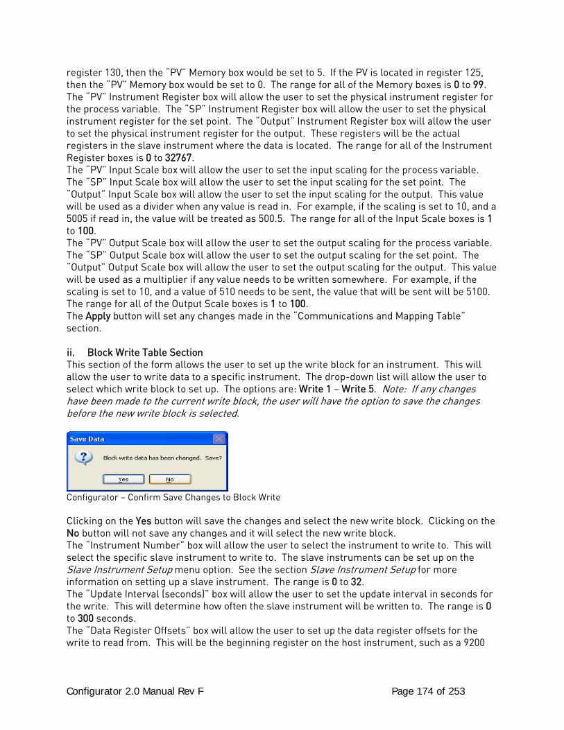
Configurator 2.0 Manual Rev F Page 174 of 253
register 130, then the “PV” Memory box would be set to 5. If the PV is located in register 125, then the “PV” Memory box would be set to 0. The range for all of the Memory boxes is 0 to 99. The “PV” Instrument Register box will allow the user to set the physical instrument register for the process variable. The “SP” Instrument Register box will allow the user to set the physical instrument register for the set point. The “Output” Instrument Register box will allow the user to set the physical instrument register for the output. These registers will be the actual registers in the slave instrument where the data is located. The range for all of the Instrument Register boxes is 0 to 32767. The “PV” Input Scale box will allow the user to set the input scaling for the process variable. The “SP” Input Scale box will allow the user to set the input scaling for the set point. The “Output” Input Scale box will allow the user to set the input scaling for the output. This value will be used as a divider when any value is read in. For example, if the scaling is set to 10, and a 5005 if read in, the value will be treated as 500.5. The range for all of the Input Scale boxes is 1 to 100. The “PV” Output Scale box will allow the user to set the output scaling for the process variable. The “SP” Output Scale box will allow the user to set the output scaling for the set point. The “Output” Output Scale box will allow the user to set the output scaling for the output. This value will be used as a multiplier if any value needs to be written somewhere. For example, if the scaling is set to 10, and a value of 510 needs to be sent, the value that will be sent will be 5100. The range for all of the Output Scale boxes is 1 to 100. The Apply button will set any changes made in the “Communications and Mapping Table” section. ii. Block Write Table Section This section of the form allows the user to set up the write block for an instrument. This will allow the user to write data to a specific instrument. The drop-down list will allow the user to select which write block to set up. The options are: Write 1 – Write 5. Note: If any changes have been made to the current write block, the user will have the option to save the changes before the new write block is selected.
Configurator – Confirm Save Changes to Block Write Clicking on the Yes button will save the changes and select the new write block. Clicking on the No button will not save any changes and it will select the new write block. The “Instrument Number” box will allow the user to select the instrument to write to. This will select the specific slave instrument to write to. The slave instruments can be set up on the Slave Instrument Setup menu option. See the section Slave Instrument Setup for more information on setting up a slave instrument. The range is 0 to 32. The “Update Interval (seconds)” box will allow the user to set the update interval in seconds for the write. This will determine how often the slave instrument will be written to. The range is 0 to 300 seconds. The “Data Register Offsets” box will allow the user to set up the data register offsets for the write to read from. This will be the beginning register on the host instrument, such as a 9200
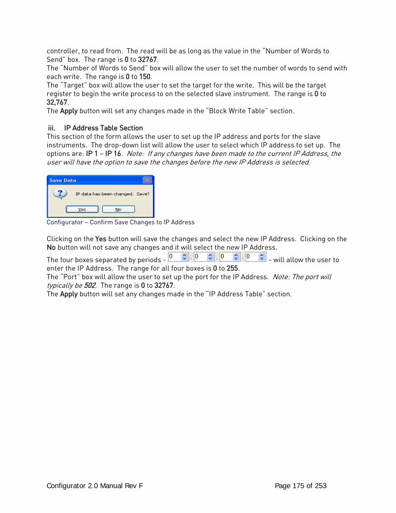
Configurator 2.0 Manual Rev F Page 175 of 253
controller, to read from. The read will be as long as the value in the “Number of Words to Send” box. The range is 0 to 32767. The “Number of Words to Send” box will allow the user to set the number of words to send with each write. The range is 0 to 150. The “Target” box will allow the user to set the target for the write. This will be the target register to begin the write process to on the selected slave instrument. The range is 0 to 32,767. The Apply button will set any changes made in the “Block Write Table” section. iii. IP Address Table Section This section of the form allows the user to set up the IP address and ports for the slave instruments. The drop-down list will allow the user to select which IP address to set up. The options are: IP 1 – IP 16. Note: If any changes have been made to the current IP Address, the user will have the option to save the changes before the new IP Address is selected.
Configurator – Confirm Save Changes to IP Address Clicking on the Yes button will save the changes and select the new IP Address. Clicking on the No button will not save any changes and it will select the new IP Address.
The four boxes separated by periods - - will allow the user to enter the IP Address. The range for all four boxes is 0 to 255. The “Port” box will allow the user to set up the port for the IP Address. Note: The port will typically be 502. The range is 0 to 32767. The Apply button will set any changes made in the “IP Address Table” section.
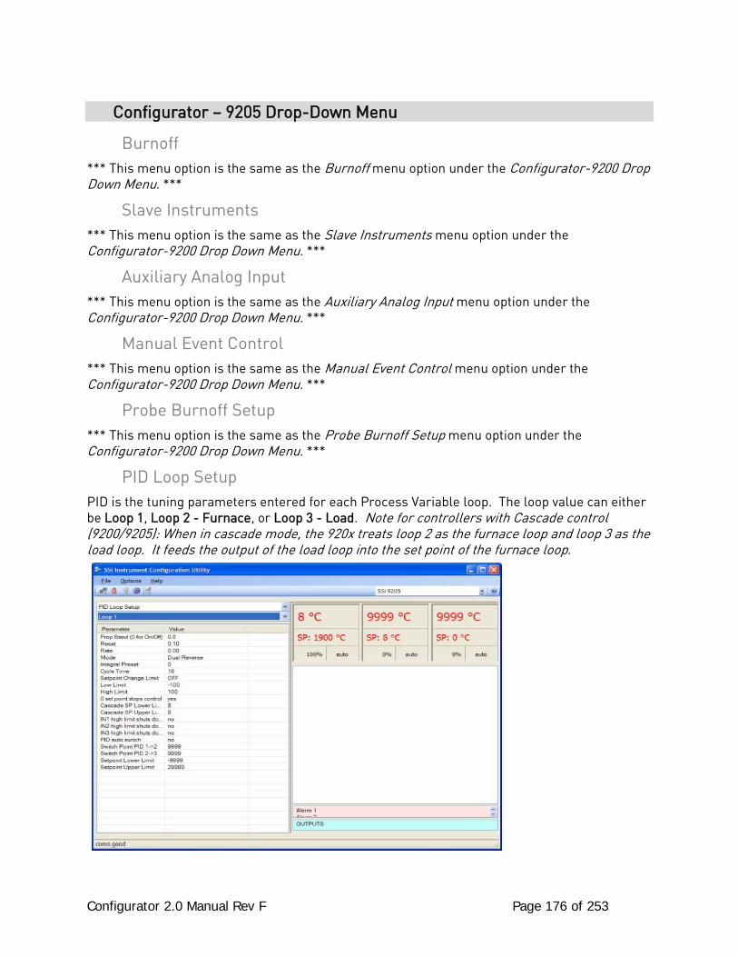
Configurator 2.0 Manual Rev F Page 176 of 253
Configurator – 9205 Drop-Down Menu
Burnoff *** This menu option is the same as the Burnoff menu option under the Configurator-9200 Drop Down Menu. ***
Slave Instruments *** This menu option is the same as the Slave Instruments menu option under the Configurator-9200 Drop Down Menu. ***
Auxiliary Analog Input *** This menu option is the same as the Auxiliary Analog Input menu option under the Configurator-9200 Drop Down Menu. ***
Manual Event Control *** This menu option is the same as the Manual Event Control menu option under the Configurator-9200 Drop Down Menu. ***
Probe Burnoff Setup *** This menu option is the same as the Probe Burnoff Setup menu option under the Configurator-9200 Drop Down Menu. ***
PID Loop Setup PID is the tuning parameters entered for each Process Variable loop. The loop value can either be Loop 1, Loop 2 - Furnace, or Loop 3 - Load. Note for controllers with Cascade control (9200/9205): When in cascade mode, the 920x treats loop 2 as the furnace loop and loop 3 as the load loop. It feeds the output of the load loop into the set point of the furnace loop.
Configurator 2.0 Manual Rev F Page 177 of 253
Prop Band (0 for On/Off) This is the proportional band field. P = Proportional (Prop Band). This is a field in which you want to stay around the setpoint. The range 0 – 999.0 Reset This is the reset field. I = Integral (Reset). This is the actual temperature being monitored over a period of time and then averaged to keep within the Proportional band. The reset is in repeats per minute. This affects the output of the controller. It will be proportional to the amount of time the error is present. This helps to eliminate offset. The range 0 – 100.00 Rate This is the rate field. D = Derivative (Rate). This is the sudden change or rate in the temperature. This rate is in minutes. This affects the controller output which is proportional to the rate of change of the measurement and will control the amount of output by time restraints. Thus derivative takes action to inhibit more rapid changes of the measurement than proportional action. Derivative is often used to avoid overshoot. The range is 0 – 100.00. The rate is not typically used for heating/carbon Mode This is the mode of the loop. The values are: Dual Reverse, Single Reverse, Dual Direct, or Single Direct. Dual – This has two output relays which can increase and decrease to achieve your SP. Single – This has one relay which works in only one direction to achieve your SP. Direct - If the PV - SP equals a positive number and the output would bring the PV down toward setpoint that is direct. Reverse – If the PV - SP equals a negative number and the output would bring the PV up toward setpoint then that is reverse Example: If a 12 mA output drives a 0 degree F temp. (PV) up to a 1200 degree F temp. (SP) this would be REVERSE and since this would take a SINGLE output from the controller the Mode for the Temperature Loop is Single Reverse. Integral Preset This field provides an offset for the starting point for PID control, also referred to as “Load Line” or “Manual Reset”. The range is –100 to 100. Cycle Time This field is typically set to the valve travel time multiplied by 1.5. Setpoint Change Limit This is a smart time feature that allows Process Loop to use PB only without Reset until the Process Variable drops below the percent output set under this category. It is used to eliminate overshoot.
Configurator 2.0 Manual Rev F Page 178 of 253
The Output percentage selected under this category must be above the normal operating output percentage of the furnace at heat. Example – if the furnace runs at 40% output at heat for the maximum load, the setpoint change limit should be set to 60%. Low Limit This is the low limit field. The range is –100 to 100. High Limit This is the high limit field. The range is –100 to 100. 0 Setpoint Stops Control If the Setpoint is zero, then all outputs are turned off. The option is either Yes or No. Cascade SP Lower Limit: This is the cascade setpoint low limit. The 9205 uses the difference between the cascade SP lower limit and the cascade SP upper limit and multiplies that value by the % output of the load loop. It then offsets this value by the cascade SP lower limit and feeds the furnace loop this value as a setpoint. Cascade SP Upper Limit: This is the cascade setpoint upper limit. The 9205 uses the difference between the cascade SP lower limit and the cascade SP upper limit and multiplies that value by the % output of the load loop. It then offsets this value by the cascade SP lower limit and feeds the furnace loop this value as a setpoint. Example: Cascade SP Lower Limit: 0 Cascade SP Upper Limit: 2000 The load has a setpoint of 1700 and it is at 37 % output. The furnace setpoint will be calculated as follows: (2000 – 0) * 0.37 + 0 = 740. IN1 high limit shuts down ctrl If input 1’s high limit is reached, then all outputs are turned off. The value can either be Yes or No. IN2 high limit shuts down ctrl If input 2’s high limit is reached, then all outputs are turned off. The value can either be Yes or No. IN3 high limit shuts down ctrl If input 3’s high limit is reached, then all outputs are turned off. The value can either be Yes or No. PID Auto Switch This is the PID auto switch field. The value can either be Yes or No. Switch Point PID 1 -> 2 This is the PID Switch Point field. The range is –300 to 4000.
Configurator 2.0 Manual Rev F Page 179 of 253
Switch Point PID 2 -> 3 This is the PID Switch Point field. The range is –300 to 4000. Setpoint Lower Limit: This is the setpoint lower limit for the loop. The range is -9999 to 9999. Setpoint Upper Limit: This is the setpoint upper limit for the loop. The range is -29999 to 29999.
Event Run Program Setup *** This menu option is the same as the Event Run Program Setup menu option under the Configurator-9200 Drop Down Menu. ***
Zone/Load TC Setup *** This menu option is the same as the Zone/Load TC Setup menu option under the Configurator-9200 Drop Down Menu. ***
Port Setup *** This menu option is the same as the Port Setup menu option under the Configurator-9200 Drop Down Menu. ***
Slave Instrument Setup *** This menu option is the same as the Slave Instrument Setup menu option under the Configurator-9200 Drop Down Menu. ***
Zone Assignments *** This menu option is the same as the Zone Assignments menu option under the Configurator-9200 Drop Down Menu. ***
Furnace Setup The Furnace Setup menu option is an administrative access only option. Do not make any adjustments on this screen without first contacting Super Systems Inc. Note for controllers with Cascade control (9200/9205): When in cascade mode, the 920x treats loop 2 as the furnace loop and loop 3 as the load loop. It feeds the output of the load loop into the set point of the furnace loop.
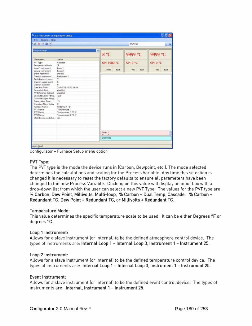
Configurator 2.0 Manual Rev F Page 180 of 253
Configurator – Furnace Setup menu option PVT Type: The PVT type is the mode the device runs in (Carbon, Dewpoint, etc.). The mode selected determines the calculations and scaling for the Process Variable. Any time this selection is changed it is necessary to reset the factory defaults to ensure all parameters have been changed to the new Process Variable. Clicking on this value will display an input box with a drop-down list from which the user can select a new PVT Type. The values for the PVT type are: % Carbon, Dew Point, Millivolts, Multi-loop, % Carbon + Dual Temp, Cascade, % Carbon + Redundant TC, Dew Point + Redundant TC, or Millivolts + Redundant TC. Temperature Mode: This value determines the specific temperature scale to be used. It can be either Degrees °F or degrees °C. Loop 1 Instrument: Allows for a slave instrument (or internal) to be the defined atmosphere control device. The types of instruments are: Internal Loop 1 – Internal Loop 3, Instrument 1 – Instrument 25. Loop 2 Instrument: Allows for a slave instrument (or internal) to be the defined temperature control device. The types of instruments are: Internal Loop 1 – Internal Loop 3, Instrument 1 – Instrument 25. Event Instrument: Allows for a slave instrument (or internal) to be the defined event control device. The types of instruments are: Internal, Instrument 1 – Instrument 25.
Configurator 2.0 Manual Rev F Page 181 of 253
Quench Instrument: Allows for slave instrument (or internal) to be the defined quench control device. The types of instruments are: Internal Loop 1 – Internal Loop 3, Instrument 1 – Instrument 25. End of Quench Event: Tells the programmer which event to signal end of quench (related to which relay it is assigned). The list of possible values is: 0 – 14. Quench Speed Event: Tells the programmer which event will signal the quench speed. The list of possible values is: 0 – 14. Quench Run Event: Tells the programmer which event will signal quench run. The list of possible values is: 0 – 14. Date and Time: This value is the current date and time on the 9205 controller only (not the local computer or the touch screen, if applicable). Clicking on the “Value” column will allow the user to set a new date and time on the controller. Note: The date and time of the touch screen can be changed (if necessary) by selecting the date and time in the lower right corner on the touch screen under the menu. This can be reached by going through the menu, and shutting down the software. Then, at the CE screen the date and time can be changed by double taping the time in the bottom right corner and setting it, then select “apply”. For this to take effect the screen needs to be rebooted; on the older TPC 642 displays the registry needs to be saved under TPC Configuration icon, the Misc Tab and then reboot the touch screen. The date and time that is recorded on the flash card (and therefore the datalog data) is the date and time of the Advantech display not the controller. Cascade Inhibit: Note: This field is only applicable if the controller is in Cascade mode. This will turn cascade control on or off. When inhibit = enabled, the 9205 functions as a multi-loop controller with three control loops. The options are: enabled or disabled. PV Difference Cutback: Note: This field is only applicable if the controller is in Cascade Mode. This is used with the Cascade Lower Range EOPV and Cascade Upper Range EOPV to limit the absolute % output of the furnace loop. This will turn the PV difference cutback feature on or off. The options are: enabled or disabled. Cascade Lower Range EOPV: Note: This field is only applicable if the controller is in Cascade Mode. This is the cascade lower range end of PV difference. This is used with the PV Difference Cutback and Cascade Upper Range EOPV to limit the absolute % output of the furnace loop. Between the lower range EPOV and the upper range EOPV, there is a linear interpolation from 0 to the loop 2 output maximum (usually 100 %) that determines the maximum % output for the furnace loop. The range is -300 to 10000.
Configurator 2.0 Manual Rev F Page 182 of 253
Cascade Upper Range EOPV: Note: This field is only applicable if the controller is in Cascade Mode. This is the cascade upper range end of PV difference. This is used with the Cascade Lower Range EOPV and PV Difference Cutback to limit the absolute % output of the furnace loop. Between the lower range EPOV and the upper range EOPV, there is a linear interpolation from 0 to the loop 2 output maximum (usually 100 %) that determines the maximum % output for the furnace loop. The range is -300 to 10000. Example: With the lower EOPV set to 10 and the upper EOPV set to 110, if the load PV is 1700 and the furnace PV is 1710, the full 100% output is available. If the load PV is 1600 and the furnace PV is 1710, the furnace output will not go above 0%. If the load PV is 1655 and the furnace PV is 1710, the maximum output for the furnace loop will be limited to 55%: (1710 – 1655)/(110-10) * (1.0). Default Hold Time: This value is the default holding time for the furnace. The range is 0 to 10000. Deviation Alarm delay: This value is the delay for the alarm if a deviation alarm is detected. The range is 0 to 10000. Furnace Name: This is the name of the furnace. PV1 Name: This is the name of process variable 1. PV2 Name: This is the name of process variable 2. PV3 Name: This is the name of process variable 3. Clear events, end of recipe: This will clear any events at the end of a recipe. The options are: yes or no.
Default Wait Limits *** This menu option is the same as the Default Wait Limits menu option under the Configurator-9200 Drop Down Menu. ***
Furnace Name *** This menu option is the same as the Furnace Name menu option under the Configurator-9200 Drop Down Menu. ***
Alarm Setup *** This menu option is the same as the Alarm Setup menu option under the Configurator-9200 Drop Down Menu. ***
Configurator 2.0 Manual Rev F Page 183 of 253
Relay Assignments *** This menu option is the same as the Relay Assignments menu option under the Configurator-9200 Drop Down Menu. ***
Relay Setpoints *** This menu option is the same as the Relay Setpoints menu option under the Configurator-9200 Drop Down Menu. ***
Analog Input Setup *** This menu option is the same as the Analog Input Setup menu option under the Configurator-9220 Drop Down Menu. ***
Analog Output Setup *** This menu option is the same as the Analog Output Setup menu option under the Configurator-9200 Drop Down Menu. ***
Passcode and Alarm *** This menu option is the same as the Passcode and Alarm menu option under the Configurator-9200 Drop Down Menu. ***
IP Address *** This menu option is the same as the IP Address menu option under the Configurator-9200 Drop Down Menu. ***
Event Control *** This menu option is the same as the Event Control menu option under the Configurator-9200 Drop Down Menu. ***
Set Menu Security *** This menu option is the same as the Set Menu Security menu option under the Configurator-9200 Drop Down Menu. ***
Curve Entry *** This menu option is the same as the Custom Curves menu option under the Configurator-9200 Drop Down Menu. ***
Alternate PID Setup *** This menu option is the same as the Alternate PID Setup menu option under the Configurator-9200 Drop Down Menu. ***
SSi Analog Input Setup *** This menu option is the same as the SSi Analog Input Setup menu option under the Configurator-9200 Drop Down Menu. ***
Configurator 2.0 Manual Rev F Page 184 of 253
SSi Configuration and Calibration *** This menu option is the same as the SSi Configuration and Calibration menu option under the Configurator-9200 Drop Down Menu. ***
ADAM Module Offset Correction *** This menu option is the same as the ADAM Module Offset Correction menu option under the Configurator-9200 Drop Down Menu. ***
Aux Setpoint Configuration *** This menu option is the same as the Aux Setpoint Configuration menu option under the Configurator-9200 Drop Down Menu. ***
Configurator 2.0 Manual Rev F Page 185 of 253
Configurator – 9210 Drop-Down Menu
Slave Instruments *** This menu option is the same as the Slave Instruments menu option under the Configurator-9200 Drop Down Menu. ***
Auxiliary Analog Input *** This menu option is the same as the Auxiliary Analog Input menu option under the Configurator-9200 Drop Down Menu. ***
Manual Event Control *** This menu option is the same as the Manual Event Control menu option under the Configurator-9200 Drop Down Menu. ***
PID Loop Setup *** This menu option is the same as the PID Loop Setup menu option under the Configurator-9200 Drop Down Menu. ***
Event Run Program Setup *** This menu option is the same as the Event Run Program Setup menu option under the Configurator-9200 Drop Down Menu. ***
Zone/Load TC Setup *** This menu option is the same as the Zone/Load TC Setup menu option under the Configurator-9200 Drop Down Menu. ***
Port Setup *** This menu option is the same as the Port Setup menu option under the Configurator-9200 Drop Down Menu. ***
Slave Instrument Setup *** This menu option is the same as the Slave Instrument Setup menu option under the Configurator-9200 Drop Down Menu. ***
Zone Assignments *** This menu option is the same as the Zone Assignments menu option under the Configurator-9200 Drop Down Menu. ***
Furnace Setup *** This menu option is the same as the Furnace Setup menu option under the Configurator-9200 Drop Down Menu. ***
Default Wait Limits *** This menu option is the same as the Default Wait Limits menu option under the Configurator-9200 Drop Down Menu. ***
Configurator 2.0 Manual Rev F Page 186 of 253
Furnace Name *** This menu option is the same as the Furnace Name menu option under the Configurator-9200 Drop Down Menu. ***
Alarm Setup *** This menu option is the same as the Alarm Setup menu option under the Configurator-9200 Drop Down Menu. ***
Relay Assignments *** This menu option is the same as the Relay Assignments menu option under the Configurator-9200 Drop Down Menu. ***
Relay Setpoints *** This menu option is the same as the Relay Setpoints menu option under the Configurator-9200 Drop Down Menu. ***
Analog Input Setup *** This menu option is the same as the Analog Input Setup menu option under the Configurator-9200 Drop Down Menu. ***
Analog Output Setup *** This menu option is the same as the Analog Output Setup menu option under the Configurator-9200 Drop Down Menu. ***
Passcode and Alarm *** This menu option is the same as the Passcode and Alarm menu option under the Configurator-9200 Drop Down Menu. ***
IP Address *** This menu option is the same as the IP Address menu option under the Configurator-9200 Drop Down Menu. ***
Event Control *** This menu option is the same as the Event Control menu option under the Configurator-9200 Drop Down Menu. ***
Valve Configuration *** This menu option is the same as the Valve Configuration menu option under the Configurator-9215 Drop Down Menu. ***
Valve Setup *** This menu option is the same as the Valve Setup menu option under the Configurator-9215 Drop Down Menu. ***
Configurator 2.0 Manual Rev F Page 187 of 253
Set Menu Security *** This menu option is the same as the Set Menu Security menu option under the Configurator-9200 Drop Down Menu. ***
Curve Entry *** This menu option is the same as the Custom Curves menu option under the Configurator-9200 Drop Down Menu. ***
Alternate PID Setup *** This menu option is the same as the Alternate PID Setup menu option under the Configurator-9200 Drop Down Menu. ***
SSi Analog Input Setup *** This menu option is the same as the SSi Analog Input Setup menu option under the Configurator-9200 Drop Down Menu. ***
SSi Configuration and Calibration *** This menu option is the same as the SSI Configuration and Calibration menu option under the Configurator-9200 Drop Down Menu. ***
ADAM Module Offset Correction *** This menu option is the same as the ADAM Module Offset Correction menu option under the Configurator-9200 Drop Down Menu. ***
Aux Setpoint Configuration *** This menu option is the same as the Aux Setpoint Configuration menu option under the Configurator-9200 Drop Down Menu. ***
TC Extension Correction Curves *** This menu option is the same as the TC Extension Correction Curves menu option under the Configurator-9200 Drop Down Menu. ***
Tuning Assistant *** This menu option is the same as the Tuning Assistant menu option under the Configurator-9200 Drop Down Menu. ***
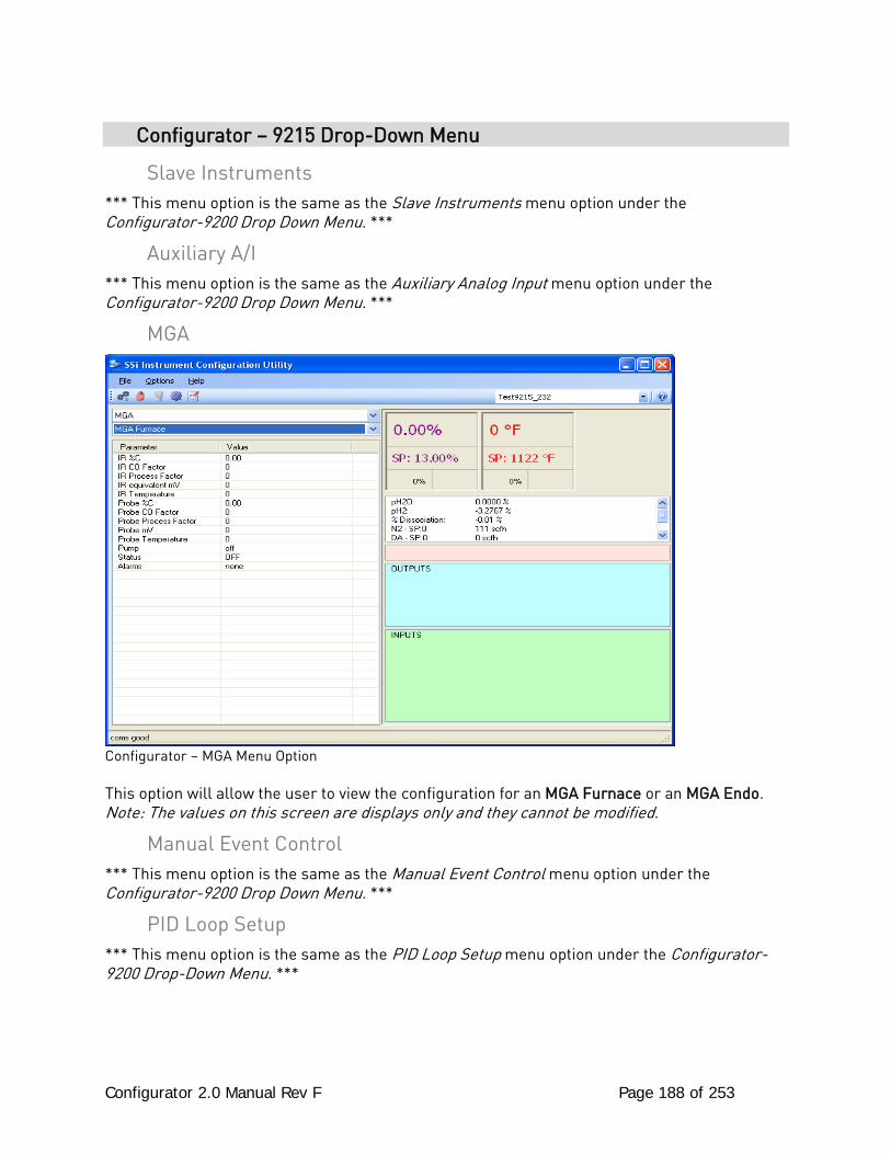
Configurator 2.0 Manual Rev F Page 188 of 253
Configurator – 9215 Drop-Down Menu
Slave Instruments *** This menu option is the same as the Slave Instruments menu option under the Configurator-9200 Drop Down Menu. ***
Auxiliary A/I *** This menu option is the same as the Auxiliary Analog Input menu option under the Configurator-9200 Drop Down Menu. ***
MGA
Configurator – MGA Menu Option This option will allow the user to view the configuration for an MGA Furnace or an MGA Endo. Note: The values on this screen are displays only and they cannot be modified.
Manual Event Control *** This menu option is the same as the Manual Event Control menu option under the Configurator-9200 Drop Down Menu. ***
PID Loop Setup *** This menu option is the same as the PID Loop Setup menu option under the Configurator-9200 Drop-Down Menu. ***
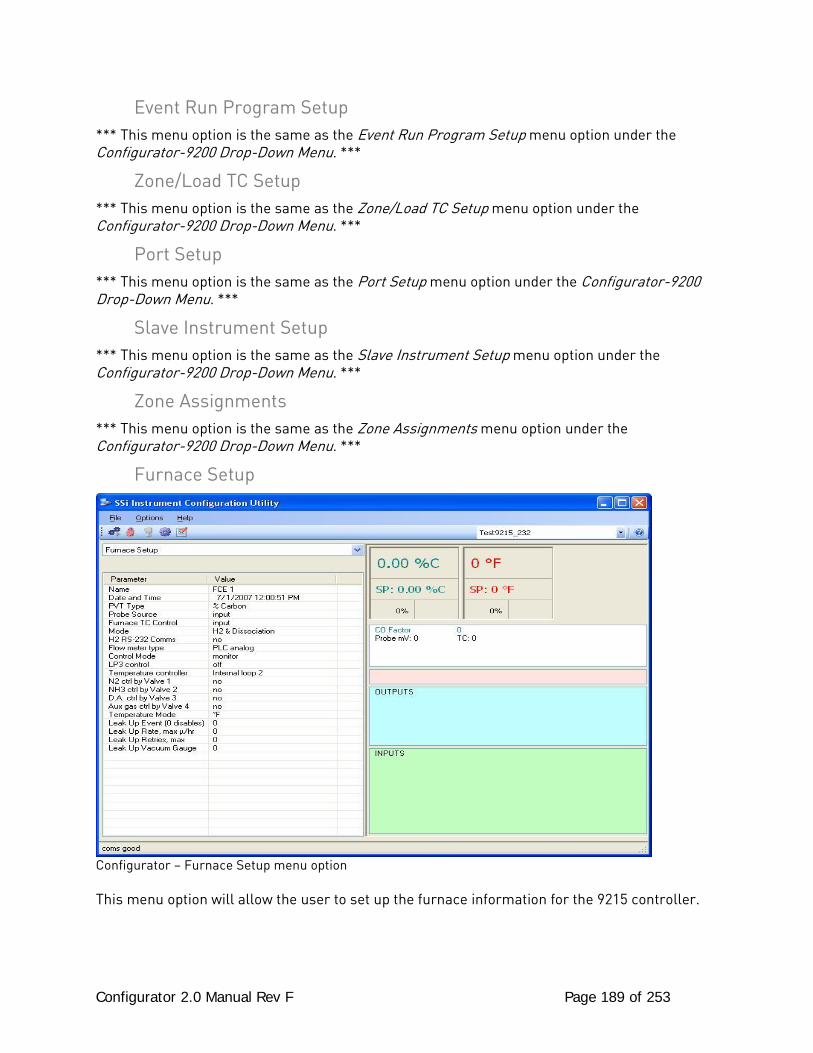
Configurator 2.0 Manual Rev F Page 189 of 253
Event Run Program Setup *** This menu option is the same as the Event Run Program Setup menu option under the Configurator-9200 Drop-Down Menu. ***
Zone/Load TC Setup *** This menu option is the same as the Zone/Load TC Setup menu option under the Configurator-9200 Drop-Down Menu. ***
Port Setup *** This menu option is the same as the Port Setup menu option under the Configurator-9200 Drop-Down Menu. ***
Slave Instrument Setup *** This menu option is the same as the Slave Instrument Setup menu option under the Configurator-9200 Drop-Down Menu. ***
Zone Assignments *** This menu option is the same as the Zone Assignments menu option under the Configurator-9200 Drop-Down Menu. ***
Furnace Setup
Configurator – Furnace Setup menu option This menu option will allow the user to set up the furnace information for the 9215 controller.
Configurator 2.0 Manual Rev F Page 190 of 253
Name: This option will allow the user to set a descriptive name for the furnace. Date and Time: This value is the current date and time on the 9215 controller only (not the local computer or the touch screen, if applicable). Clicking on the “Value” column will allow the user to set a new date and time on the controller. Note: The date and time of the touch screen can be changed (if necessary) by selecting the date and time in the lower right corner on the touch screen under the menu. This can be reached by going through the menu, and shutting down the software. Then, at the CE screen the date and time can be changed by double taping the time in the bottom right corner and setting it, then select “apply”. For this to take effect the screen needs to be rebooted; on the older TPC 642 displays the registry needs to be saved under TPC Configuration icon, the Misc Tab and then reboot the touch screen. The date and time that is recorded on the flash card (and therefore the datalog data) is the date and time of the Advantech display not the controller. PVT Type: This option will let the user set the PVT type for the controller. The options are: % Carbon, Nitrider, or FNC. Probe Source: This option will allow the user to set the probe source for the 9215 controller. The options are: Input or PLC. Furnace TC Control: This option will allow the user to set the TC control for the furnace. The options are: Input or PLC. Mode: This option will let the user set the mode of the controller. The options are: H2 & Disassociation or H2 & Nitrider Potential. H2 RS-232 Comms: This option will allow the user to determine if there will be RS-232 communications with the H2. The options are: Yes or No. Flow Meter Type: This option will allow the user to set the flow meter type for the controller. The options are: PLC Analog or SSi RS485. Control Mode: This option will allow the user to set the control mode for the controller. The options are: Monitor or Control. LP3 Control: This option will allow the user to set the control for the LP3. The options are: None, Pressure Control, Not Defined, or Temperature.
Configurator 2.0 Manual Rev F Page 191 of 253
Temperature Controller: This option will allow the user to define the temperature control for the 9215 controller. The options are: Internal Loop 2 or SPP TC Instrument. N2 Ctrl by Valve 1: This option will determine if the N2 can be controlled by valve 1. The options are: No or Yes. NH3 Ctrl by Valve 2: This option will determine if the NH3 can be controlled by valve 2. The options are: No or Yes. D.A. Ctrl by Valve 3: This option will determine if the D.A. (Disassociated Ammonia) can be controlled by valve 3. The options are: No or Yes. Aux gas Ctrl by Valve 4: This option will determine if the auxiliary gas can be controlled by valve 4. The options are: No or Yes. Temperature Mode: This option will set the temperature mode for the controller. The options are: °F (Degrees Fahrenheit) or °C (Degrees Celsius). Leak Up Event (0 Disables): This option will allow the user to set the leak up event number. The range is: 0 to 48. Leak Up Rate, Max /hr : This option allows the user to set the maximum leak up rate. The range is: 0 to 65. Leak Up Retries, Max: This option allows the user to set the maximum number of retires for the leak up process. The range is: 0 to 500. Leak Up Vacuum Gauge: This option will allow the user to set the leak up gauge number. The range is: 1 to 4.
Default Wait Limits *** This menu option is the same as the Default Wait Limits menu option under the Configurator-9200 Drop-Down Menu. ***
Alarm Setup *** This menu option is the same as the Alarm Setup menu option under the Configurator-9200 Drop-Down Menu. ***
Relay Assignments *** This menu option is the same as the Relay Assignments menu option under the Configurator-9200 Drop-Down Menu. ***
Configurator 2.0 Manual Rev F Page 192 of 253
Relay Setpoints *** This menu option is the same as the Relay Setpoints menu option under the Configurator-9200 Drop-Down Menu. ***
Analog Input Setup *** This menu option is the same as the Analog Input Setup menu option under the Configurator-9200 Drop-Down Menu. ***
Analog Output Setup *** This menu option is the same as the Analog Output Setup menu option under the Configurator-9200 Drop-Down Menu. ***
Passcode and Alarm *** This menu option is the same as the Passcode and Alarm menu option under the Configurator-9200 Drop-Down Menu. ***
Generic Mapping Setups *** This menu option is the same as the Generic Mapping Setups menu option under the Configurator-9005 Drop-Down Menu. ***
DF1 Configuration *** This menu option is the same as the DF1 Configuration menu option under the Configurator-9005 Drop-Down Menu. ***
IP Address *** This menu option is the same as the IP Address menu option under the Configurator-9200 Drop-Down Menu. ***
Event Control *** This menu option is the same as the Event Control menu option under the Configurator-9200 Drop-Down Menu. ***
Vacuum Gauge Setup *** This menu option is the same as the Vacuum Gauge Setup menu option under the Configurator-9005 Drop-Down Menu. ***
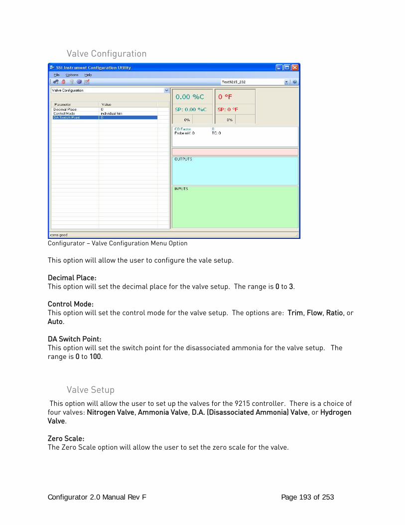
Configurator 2.0 Manual Rev F Page 193 of 253
Valve Configuration
Configurator – Valve Configuration Menu Option This option will allow the user to configure the vale setup. Decimal Place: This option will set the decimal place for the valve setup. The range is 0 to 3. Control Mode: This option will set the control mode for the valve setup. The options are: Trim, Flow, Ratio, or Auto. DA Switch Point: This option will set the switch point for the disassociated ammonia for the valve setup. The range is 0 to 100.
Valve Setup This option will allow the user to set up the valves for the 9215 controller. There is a choice of four valves: Nitrogen Valve, Ammonia Valve, D.A. (Disassociated Ammonia) Valve, or Hydrogen Valve. Zero Scale: The Zero Scale option will allow the user to set the zero scale for the valve.
Configurator 2.0 Manual Rev F Page 194 of 253
Full Scale: This option will allow the user to set the full scale for the vale. Trim Enable: This option will allow the user to set the trim enable option for the valve. Target Setpoint: The Target Setpoint option will allow the user to set the target setpoint for the valve. Trim Range: This option will allow the user to set the trim range for the valve. Zero SP Scale: This option will allow the user to set the zero scale for the setpoint. Full SP Scale: This option will allow the user to set the full scale for the setpoint. Valve Max: This option will allow the user to set the maximum flow rate for the valve.
Custom Curves *** This menu option is the same as the Curve Entry menu option under the Configurator-9200 Drop-Down Menu. ***
Alternate PID Setup *** This menu option is the same as the Alternate PID Setup menu option under the Configurator-9200 Drop-Down Menu. ***
SSi Analog Input Setup *** This menu option is the same as the SSi Analog Input Setup menu option under the Configurator-9200 Drop-Down Menu. ***
SSi Configuration and Calibration *** This menu option is the same as the SSi Configuration and Calibration menu option under the Configurator-9200 Drop-Down Menu. ***
ADAM Module Offset Correction *** This menu option is the same as the ADAM Module Offset Correction menu option under the Configurator-9200 Drop-Down Menu. ***
Aux Setpoint Configuration *** This menu option is the same as the Aux Setpoint Configuration menu option under the Configurator-9200 Drop-Down Menu. ***
Configurator 2.0 Manual Rev F Page 195 of 253
TC Extension Correction Curves *** This menu option is the same as the TC Extension Correction Curves menu option under the Configurator-9200 Drop-Down Menu. ***
MGA Setup Configurator – MGA Setup menu option This option will allow the user to setup the configuration for an MGA Furnace or an MGA Endo. Local Cooler ON Setpoint: This option will allow the user to set the setpoint to turn the local cooler on. The range is: -1000 to 4000. Local Cooler OFF Setpoint: This option will allow the user to set the setpoint to turn the local cooler off. The range is: -1000 to 4000. Auto Cal: This option will turn the auto calibration process on or off. The options are: On or Off. Sequencing: This option will turn the sequencing process on or off. The options are: On or Off. Sequence Mode: This option will set the mode for the sequencing process. The options are: Normal or Specific. Active CH: This option will allow the user to select the active CH gas. The options are: CH 1 through CH 6. Note: More than one gas may be selected as the active CH value. Auto Cal Interval (min) (0 = OFF): This option will set the auto cal interval in minutes. The range is: 0 to 9999. Auto Zero Interval (min) (0 = OFF): This option will set the auto zero cal interval in minutes. The range is: 0 to 9999. Auto Data Display Time: This is a display of the auto data time. This value cannot be modified. Purge Time Before Cal/Zero: This is a display of the purge time before the next calibration/zero process. This value cannot be modified.
Configurator 2.0 Manual Rev F Page 196 of 253
Gas 1/2/3/4/5/6 Type: This option will allow the user to select the gas type for the specified gas. The options are: None PIC 2 A/D1 O2 Cell PIC IR Cell 1 PIC 2 A/D3 ext Thermister PIC IR Cell 2 PIC 1 A/D3 ext 0-5V PIC IR Cell 3 PIC 3 A/D0 ext 0-1V PIC IR Cell 4 PIC 3 A/D1 ext 0-1V H2 Cell via RS232 PIC 3 A/D3 ext 0-5V Lambda Probe via RS485 Gas 1/2/3/4/5/6 Value: This option will display the current value for the specified gas. This value cannot be modified. Gas 1/2/3/4/5/6 Full Scale: This option will allow the user to set the full scale for the specified gas. The range is: 0 – 9999. Gas 1/2/3/4/5/6 Display Decimal Place: This option will allow the user to set the display decimal places for the specified gas. The range is: 0 to 4. Gas 1/2/3/4/5/6 Source Decimal Place: This option will allow the user to set the source decimal places for the specified gas. The range is: 0 to 4. Gas 1/2/3/4/5/6 Units: This option will allow the user to set the units for the specified gas. The options are: Blank % °F °C H2 O2
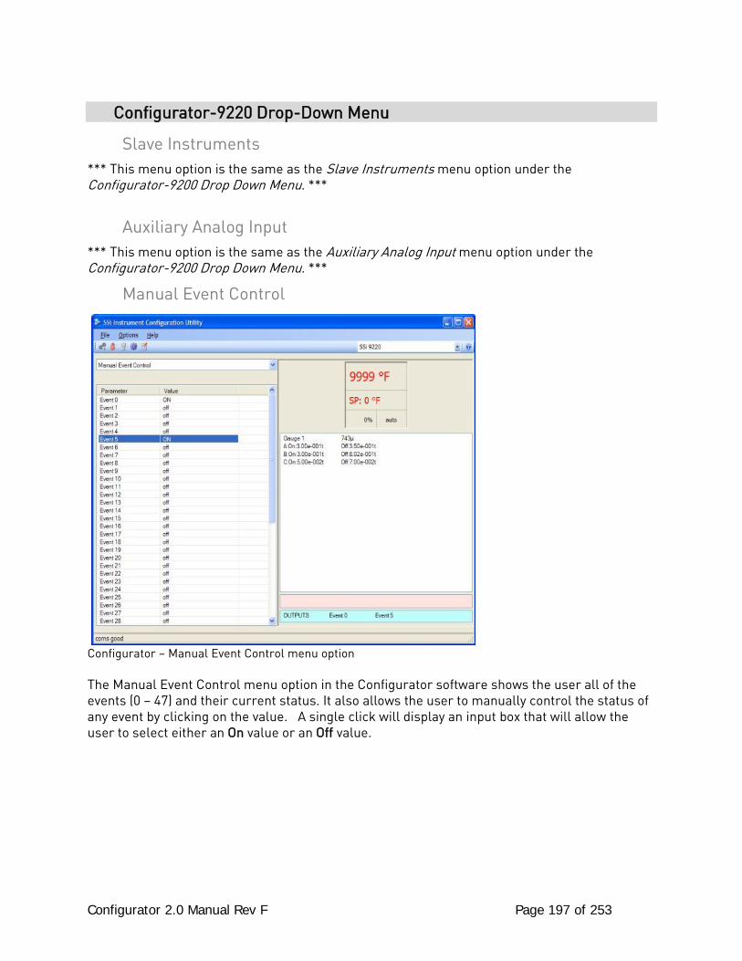
Configurator 2.0 Manual Rev F Page 197 of 253
Configurator-9220 Drop-Down Menu
Slave Instruments *** This menu option is the same as the Slave Instruments menu option under the Configurator-9200 Drop Down Menu. ***
Auxiliary Analog Input *** This menu option is the same as the Auxiliary Analog Input menu option under the Configurator-9200 Drop Down Menu. ***
Manual Event Control
Configurator – Manual Event Control menu option The Manual Event Control menu option in the Configurator software shows the user all of the events (0 – 47) and their current status. It also allows the user to manually control the status of any event by clicking on the value. A single click will display an input box that will allow the user to select either an On value or an Off value.
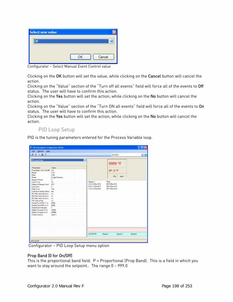
Configurator 2.0 Manual Rev F Page 198 of 253
Configurator – Select Manual Event Control value Clicking on the OK button will set the value, while clicking on the Cancel button will cancel the action. Clicking on the “Value” section of the “Turn off all events” field will force all of the events to Off status. The user will have to confirm this action. Clicking on the Yes button will set the action, while clicking on the No button will cancel the action. Clicking on the “Value” section of the “Turn ON all events” field will force all of the events to On status. The user will have to confirm this action. Clicking on the Yes button will set the action, while clicking on the No button will cancel the action.
PID Loop Setup PID is the tuning parameters entered for the Process Variable loop.
Configurator – PID Loop Setup menu option Prop Band (0 for On/Off) This is the proportional band field. P = Proportional (Prop Band). This is a field in which you want to stay around the setpoint.. The range 0 – 999.0
Configurator 2.0 Manual Rev F Page 199 of 253
Reset This is the reset field. I = Integral (Reset). This is the actual temperature being monitored over a period of time and then averaged to keep within the Proportional band. The reset is in repeats per minute. This affects the output of the controller. It will be proportional to the amount of time the error is present. This helps to eliminate offset.. The range 0 – 100.00 Rate This is the rate field. D = Derivative (Rate). This is the sudden change or rate in the temperature. This rate is in minutes. This affects the controller output which is proportional to the rate of change of the measurement and will control the amount of output by time restraints. Thus derivative takes action to inhibit more rapid changes of the measurement than proportional action. Derivative is often used to avoid overshoot.. The range is 0 – 100.00. The rate is not typically used for heating/carbon Mode This is the mode of the loop. The values are: Dual Reverse, Single Reverse, Dual Direct, or Single Direct. Dual – This has two output relays which can increase and decrease to achieve your SP. Single – This has one relay which works in only one direction to achieve your SP. Direct - If the PV - SP equals a positive number and the output would bring the PV down toward setpoint that is direct. Reverse – If the PV - SP equals a negative number and the output would bring the PV up toward setpoint then that is reverse Example: If a 12 mA output drives a 0 degree F temp. (PV) up to a 1200 degree F temp. (SP) this would be REVERSE and since this would take a SINGLE output from the controller the Mode for the Temperature Loop is Single Reverse. Integral Preset This field provides an offset for the starting point for PID control, also referred to as “Load Line” or “Manual Reset”. The range is –100 to 100. Cycle Time This field is typically set to the valve travel time multiplied by 1.5. Setpoint Change Limit This is a smart time feature that allows Process Loop to use PB only without Reset until the Process Variable drops below the percent output set under this category. It is used to eliminate overshoot. The Output percentage selected under this category must be above the normal operating output percentage of the furnace at heat. Example – if the furnace runs at 40% output at heat for the maximum load, the setpoint change limit should be set to 60%. Low Limit This is the low limit field. The range is –100 to 100. High Limit This is the high limit field. The range is –100 to 100.
Configurator 2.0 Manual Rev F Page 200 of 253
0 Setpoint Stops Control If the Setpoint is zero, then all outputs are turned off. The option is either Yes or No. IN1 high limit shuts down ctrl If input 1’s high limit is reached, then all outputs are turned off. The value can either be Yes or No. IN2 high limit shuts down ctrl If input 2’s high limit is reached, then all outputs are turned off. The value can either be Yes or No. IN3 high limit shuts down ctrl If input 3’s high limit is reached, then all outputs are turned off. The value can either be Yes or No. PID Auto Switch This is the PID auto switch field. The value can either be Yes or No. Switch Point PID 1 -> 2 This is the PID Switch Point field. The range is –300 to 4000. Switch Point PID 2 -> 3 This is the PID Switch Point field. The range is –300 to 4000. Overshoot Limit Gain This is the Overshoot limit gain field. When calculating the control action sometimes the calculation would call for more than 100% which is not possible. The output is limited to 100%, or whatever was set in the High Limit field. The difference of the unlimited minus the limited is multiplied by the over shoot limit gain and divided by 100. This is subtracted from the control output. If the gain is 0 there is no effect. Under normal control the unlimited equals the limited and there is no effect. If there is a big change where the control loop drives hard, then the effect is to limit the drive as it approaches setpoint and limit the overshoot. The limited is the values set in the upper and lower limits fields. The unlimited would be what is calculated before limiting. For a big setpoint change, the calculations may compute 150% output, but the true output is limited to the upper limit. The range is 0 to 9999. Setpoint Lower Limit This is the lower limit of the setpoint. The range is –300 to 9999. Setpoint Upper Limit This is the upper limit for the setpoint. The range is –300 to 9999. Control Source: This is the control source for the loop. The options are: Off, Input 1, Input 2, Input 3, Vac G1 torr, Vac G1 micron, Vac G2 torr, Vac G2 micron, Vac G3 torr, Vac G3 micron, Vac G4 torr, Vac G4 micron.
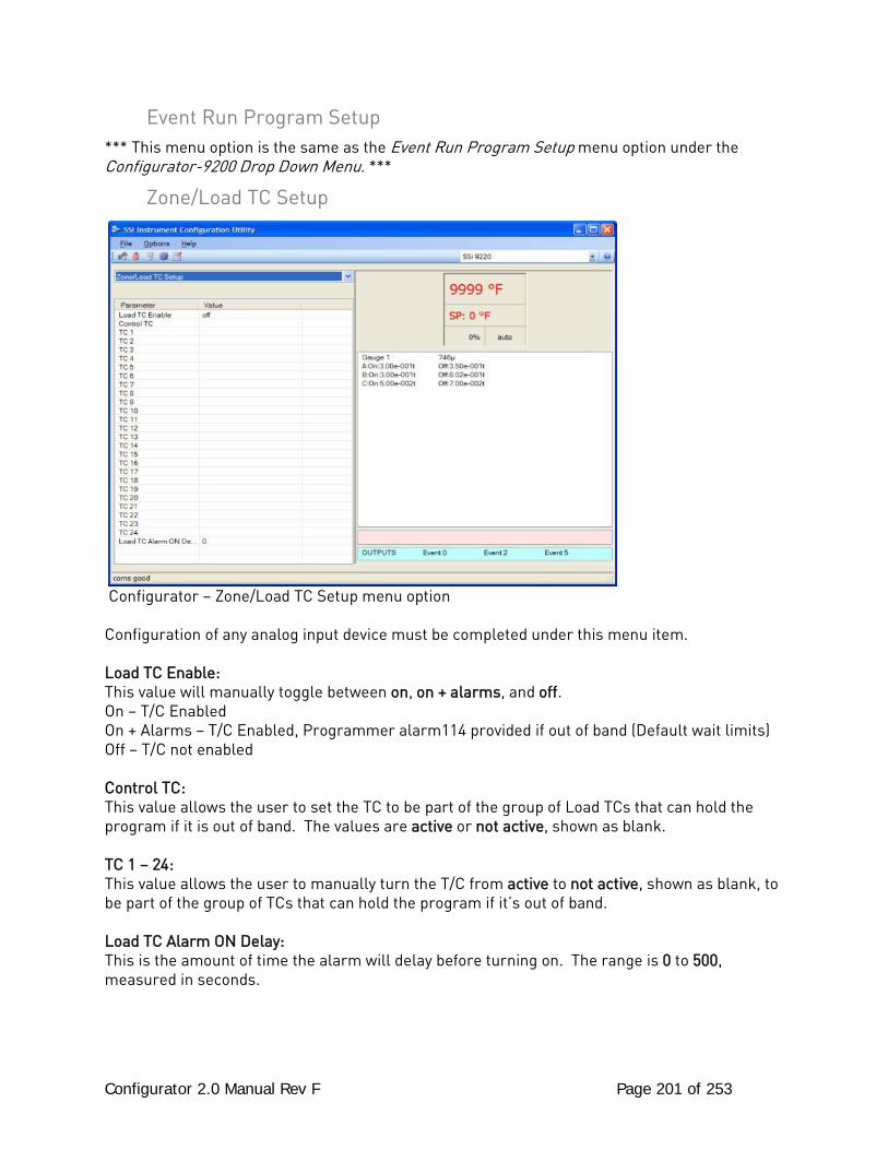
Configurator 2.0 Manual Rev F Page 201 of 253
Event Run Program Setup *** This menu option is the same as the Event Run Program Setup menu option under the Configurator-9200 Drop Down Menu. ***
Zone/Load TC Setup
Configurator – Zone/Load TC Setup menu option Configuration of any analog input device must be completed under this menu item. Load TC Enable: This value will manually toggle between on, on + alarms, and off. On – T/C Enabled On + Alarms – T/C Enabled, Programmer alarm114 provided if out of band (Default wait limits) Off – T/C not enabled Control TC: This value allows the user to set the TC to be part of the group of Load TCs that can hold the program if it is out of band. The values are active or not active, shown as blank. TC 1 – 24: This value allows the user to manually turn the T/C from active to not active, shown as blank, to be part of the group of TCs that can hold the program if it’s out of band. Load TC Alarm ON Delay: This is the amount of time the alarm will delay before turning on. The range is 0 to 500, measured in seconds.
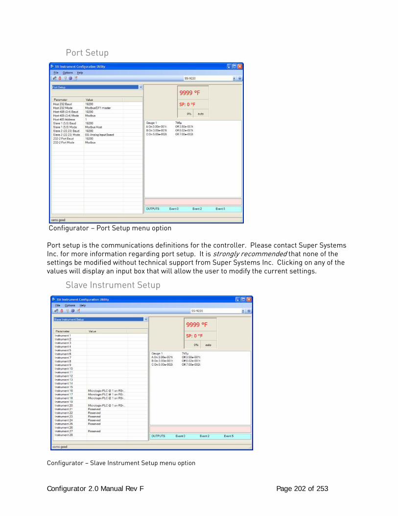
Configurator 2.0 Manual Rev F Page 202 of 253
Port Setup
Configurator – Port Setup menu option Port setup is the communications definitions for the controller. Please contact Super Systems Inc. for more information regarding port setup. It is strongly recommended that none of the settings be modified without technical support from Super Systems Inc. Clicking on any of the values will display an input box that will allow the user to modify the current settings.
Slave Instrument Setup
Configurator – Slave Instrument Setup menu option
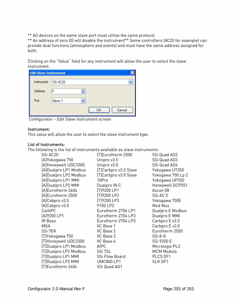
Configurator 2.0 Manual Rev F Page 203 of 253
** All devices on the same slave port must utilize the same protocol ** An address of zero (0) will disable the instrument** Some controllers (AC20 for example) can provide dual functions (atmosphere and events) and must have the same address assigned for both. Clicking on the “Value” field for any instrument will allow the user to select the slave instrument.
Configurator – Edit Slave Instrument screen Instrument: This value will allow the user to select the slave instrument type. List of Instruments: The following is the list of instruments available as slave instruments: SSi AC20 [T]Eurotherm 2500 SSi Quad AO2 [A]Yokogawa 750 Unipro v3.5 SSi Quad AO3 [A]Honeywell UDC3300 Unipro v3.0 SSi Quad AO4 [A]Dualpro LP1 Modbus [T]Carbpro v3.5 Slave Yokogawa UT350 [A]Dualpro LP2 Modbus [T]Carbpro v3.0 Slave Yokogawa 750 Lp 2 [A]Dualpro LP1 MMI 10Pro Yokogawa UP350 [A]Dualpro LP2 MMI Dualpro IN C Honeywell DCP551 [A]Eurotherm 2404 [T]9200 LP1 Ascon 08 [A]Eurotherm 2500 [T]9200 LP2 SSi AC E [A]Cabpro v3.5 [T]9200 LP3 Yokogawa 750E [A]Cabpro v3.0 9100 LP2 Mod Mux CarbPC Eurotherm 2704 LP1 Dualpro E Modbus [A]9200 LP1 Eurotherm 2704 LP2 Dualpro E MMI IR Base Eurotherm 2704 LP3 Carbpro E v3.5 MGA VC Base 1 Carbpro E v3.0 SSi 7EK VC Base 2 Eurotherm 2500 [T]Yokogawa 750 VC Base 3 SSi 8-8 [T]Honeywell UDC3300 VC Base 4 SSi 9200 E [T]Dualpro LP1 Modbus AIPC Micrologix PLC [T]Dualpro LP2 Modbus SSi 7SL MCM Module [T]Dualpro LP1 MMI SSi Flow Board PLC5 DF1 [T]Dualpro LP2 MMI UMC800 LP1 SLK DF1 [T]Eurotherm 2404 SSi Quad AO1
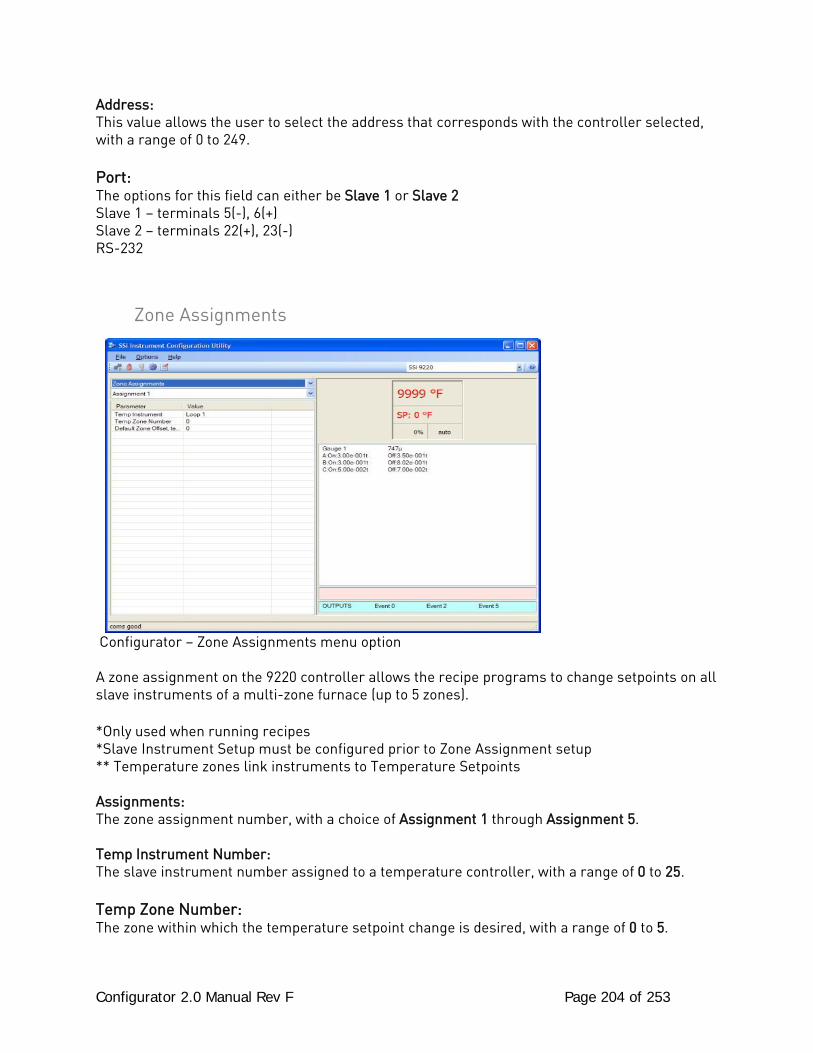
Configurator 2.0 Manual Rev F Page 204 of 253
Address: This value allows the user to select the address that corresponds with the controller selected, with a range of 0 to 249. Port: The options for this field can either be Slave 1 or Slave 2 Slave 1 – terminals 5(-), 6(+) Slave 2 – terminals 22(+), 23(-) RS-232
Zone Assignments
Configurator – Zone Assignments menu option A zone assignment on the 9220 controller allows the recipe programs to change setpoints on all slave instruments of a multi-zone furnace (up to 5 zones). *Only used when running recipes *Slave Instrument Setup must be configured prior to Zone Assignment setup ** Temperature zones link instruments to Temperature Setpoints Assignments: The zone assignment number, with a choice of Assignment 1 through Assignment 5. Temp Instrument Number: The slave instrument number assigned to a temperature controller, with a range of 0 to 25. Temp Zone Number: The zone within which the temperature setpoint change is desired, with a range of 0 to 5.
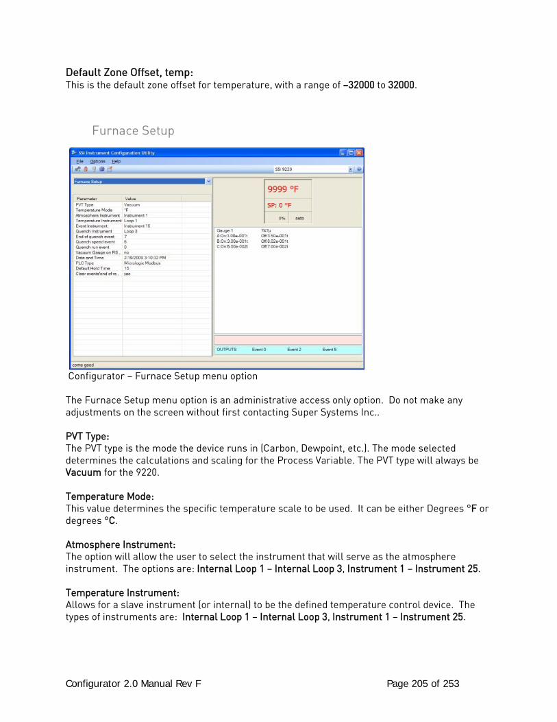
Configurator 2.0 Manual Rev F Page 205 of 253
Default Zone Offset, temp: This is the default zone offset for temperature, with a range of –32000 to 32000.
Furnace Setup
Configurator – Furnace Setup menu option The Furnace Setup menu option is an administrative access only option. Do not make any adjustments on the screen without first contacting Super Systems Inc.. PVT Type: The PVT type is the mode the device runs in (Carbon, Dewpoint, etc.). The mode selected determines the calculations and scaling for the Process Variable. The PVT type will always be Vacuum for the 9220. Temperature Mode: This value determines the specific temperature scale to be used. It can be either Degrees °F or degrees °C. Atmosphere Instrument: The option will allow the user to select the instrument that will serve as the atmosphere instrument. The options are: Internal Loop 1 – Internal Loop 3, Instrument 1 – Instrument 25. Temperature Instrument: Allows for a slave instrument (or internal) to be the defined temperature control device. The types of instruments are: Internal Loop 1 – Internal Loop 3, Instrument 1 – Instrument 25.
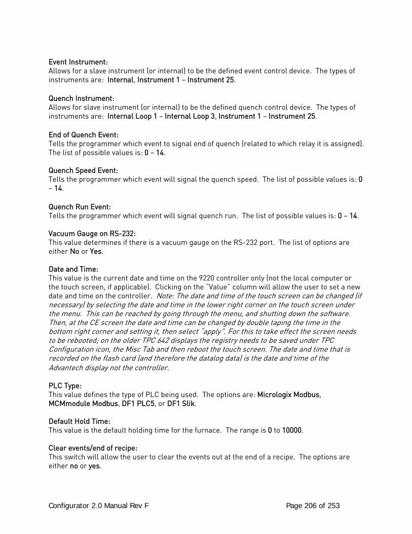
Configurator 2.0 Manual Rev F Page 206 of 253
Event Instrument: Allows for a slave instrument (or internal) to be the defined event control device. The types of instruments are: Internal, Instrument 1 – Instrument 25. Quench Instrument: Allows for slave instrument (or internal) to be the defined quench control device. The types of instruments are: Internal Loop 1 – Internal Loop 3, Instrument 1 – Instrument 25. End of Quench Event: Tells the programmer which event to signal end of quench (related to which relay it is assigned). The list of possible values is: 0 – 14. Quench Speed Event: Tells the programmer which event will signal the quench speed. The list of possible values is: 0 – 14. Quench Run Event: Tells the programmer which event will signal quench run. The list of possible values is: 0 – 14. Vacuum Gauge on RS-232: This value determines if there is a vacuum gauge on the RS-232 port. The list of options are either No or Yes. Date and Time: This value is the current date and time on the 9220 controller only (not the local computer or the touch screen, if applicable). Clicking on the “Value” column will allow the user to set a new date and time on the controller. Note: The date and time of the touch screen can be changed (if necessary) by selecting the date and time in the lower right corner on the touch screen under the menu. This can be reached by going through the menu, and shutting down the software. Then, at the CE screen the date and time can be changed by double taping the time in the bottom right corner and setting it, then select “apply”. For this to take effect the screen needs to be rebooted; on the older TPC 642 displays the registry needs to be saved under TPC Configuration icon, the Misc Tab and then reboot the touch screen. The date and time that is recorded on the flash card (and therefore the datalog data) is the date and time of the Advantech display not the controller. PLC Type: This value defines the type of PLC being used. The options are: Micrologix Modbus, MCMmodule Modbus, DF1 PLC5, or DF1 Slik. Default Hold Time: This value is the default holding time for the furnace. The range is 0 to 10000. Clear events/end of recipe: This switch will allow the user to clear the events out at the end of a recipe. The options are either no or yes.
Configurator 2.0 Manual Rev F Page 207 of 253
Default Wait Limits *** This menu option is the same as the Default Wait Limits menu option under the Configurator-9200 Drop Down Menu. ***
Furnace Name *** This menu option is the same as the Furnace Name menu option under the Configurator-9200 Drop Down Menu. ***
Alarm Setup
Configurator – Alarm Setup menu option The 9220 controller can be configured to use three different alarms, and a Thermocouple Check. Each of the alarms consists of an alarm setpoint, alarm type, alarm hysteresis, smart alarm, ON delay time, and a 0 SP blocks alarm value. The alarms come from the factory with a default configuration dependent on the application but also can be modified prior to shipment to your facility or in the field by a supervisor. Setpoint: This value is the setpoint for the alarm. Clicking on this value will display an input box from which the user can select a new value. The range is from –9999.00 to 9999.00. Alarm Type: This value is the type of alarms used. Clicking on this value will display an input box with two (2) drop-down lists from which the user can select a new value. The values in the first (top) list box are:
PV 1 Value PV 2 Value PV 3 Value Input 1 Value Input 2 Value
Configurator 2.0 Manual Rev F Page 208 of 253
Input 3 Value PO1 Value PO2 Value PO3 Value The values in the second (bottom) list box are: Process High Process Low Band, Normally Open Band, Normally Closed Deviation, Normally Open Deviation, Normally Closed Hysteresis: This value is the Hysteresis value. The Hysteresis is a set number that works with the alarm to help control a motor or pump longer to reach a set amount to come back into band before it will shut off motor or pump. Example: Using quench oil as an example, suppose the SP is 200 ◦F. The alarm is set as a deviation of +10 ◦F. At 210 ◦F, the alarm is active and the pump will run to cool the oil. With a hysteresis of 8 ◦F, the alarm and pump will turn off at 202 ◦F. It will turn back on when it is 10 ◦F above setpoint. If the setpoint is still 200 ◦F, then at 210 ◦F, it will turn on again. Clicking on this value will display an input box from which the user can select a new value. The range is from 0 to 9999. Smart Alarm: This value is a display of the Smart Alarm status. A smart alarm is an alarm that works with a Process Variable (PV), and, when enabled, it will not be active until the PV is within band of the setpoint. The alarm sounding - if active - will be disabled until within the SP band. When it is in band, the alarm will go active unless on delay time is set. Example: If the SP is 1700 and the band is 10 degrees the alarm will not be active until the PV reaches 1690. The value can be either disabled or enabled. ON Delay Time: This value is the ON Delay Time. Clicking on this value will display an input box from which the user can select a new value. The range is from 0 to 9999. 0 SP Blocks Alarm: This value will allow a 0 setpoint to block an alarm. The options are either no or yes.
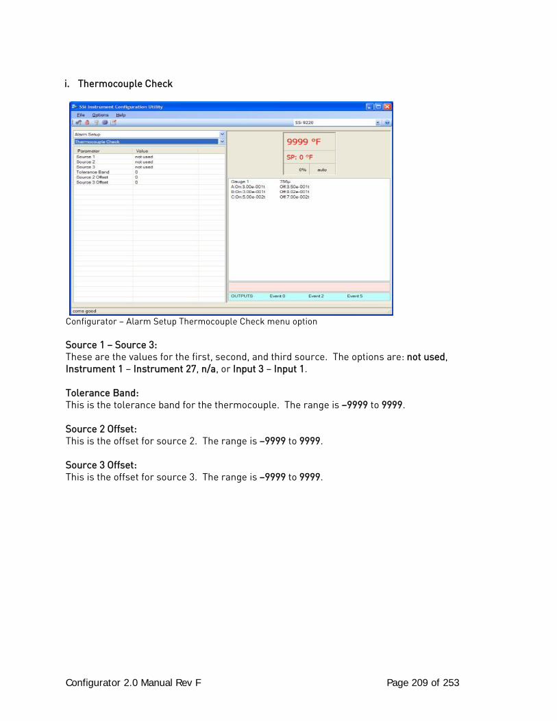
Configurator 2.0 Manual Rev F Page 209 of 253
i. Thermocouple Check
Configurator – Alarm Setup Thermocouple Check menu option Source 1 – Source 3: These are the values for the first, second, and third source. The options are: not used, Instrument 1 – Instrument 27, n/a, or Input 3 – Input 1. Tolerance Band: This is the tolerance band for the thermocouple. The range is –9999 to 9999. Source 2 Offset: This is the offset for source 2. The range is –9999 to 9999. Source 3 Offset: This is the offset for source 3. The range is –9999 to 9999.
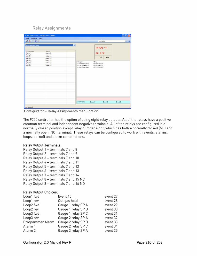
Configurator 2.0 Manual Rev F Page 210 of 253
Relay Assignments
Configurator – Relay Assignments menu option The 9220 controller has the option of using eight relay outputs. All of the relays have a positive common terminal and independent negative terminals. All of the relays are configured in a normally closed position except relay number eight, which has both a normally closed (NC) and a normally open (NO) terminal. These relays can be configured to work with events, alarms, loops, burnoff and alarm combinations. Relay Output Terminals: Relay Output 1 – terminals 7 and 8 Relay Output 2 – terminals 7 and 9 Relay Output 3 – terminals 7 and 10 Relay Output 4 – terminals 7 and 11 Relay Output 5 – terminals 7 and 12 Relay Output 6 – terminals 7 and 13 Relay Output 7 – terminals 7 and 14 Relay Output 8 – terminals 7 and 15 NC Relay Output 8 – terminals 7 and 16 NO Relay Output Choices: Loop1 fwd Event 15 event 27 Loop1 rev Out gas hold event 28 Loop2 fwd Gauge 1 relay SP A event 29 Loop2 rev Gauge 1 relay SP B event 30 Loop3 fwd Gauge 1 relay SP C event 31 Loop3 rev Gauge 2 relay SP A event 32 Programmer Alarm Gauge 2 relay SP B event 33 Alarm 1 Gauge 2 relay SP C event 34 Alarm 2 Gauge 3 relay SP A event 35
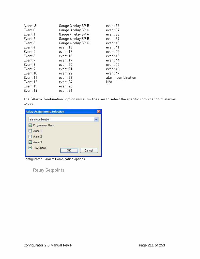
Configurator 2.0 Manual Rev F Page 211 of 253
Alarm 3 Gauge 3 relay SP B event 36 Event 0 Gauge 3 relay SP C event 37 Event 1 Gauge 4 relay SP A event 38 Event 2 Gauge 4 relay SP B event 39 Event 3 Gauge 4 relay SP C event 40 Event 4 event 16 event 41 Event 5 event 17 event 42 Event 6 event 18 event 43 Event 7 event 19 event 44 Event 8 event 20 event 45 Event 9 event 21 event 46 Event 10 event 22 event 47 Event 11 event 23 alarm combination Event 12 event 24 N/A Event 13 event 25 Event 14 event 26 The “Alarm Combination” option will allow the user to select the specific combination of alarms to use.
Configurator – Alarm Combination options
Relay Setpoints
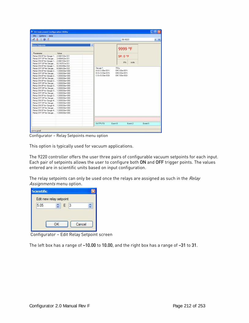
Configurator 2.0 Manual Rev F Page 212 of 253
Configurator – Relay Setpoints menu option This option is typically used for vacuum applications. The 9220 controller offers the user three pairs of configurable vacuum setpoints for each input. Each pair of setpoints allows the user to configure both ON and OFF trigger points. The values entered are in scientific units based on input configuration. The relay setpoints can only be used once the relays are assigned as such in the Relay Assignments menu option.
Configurator – Edit Relay Setpoint screen The left box has a range of –10.00 to 10.00, and the right box has a range of –31 to 31.
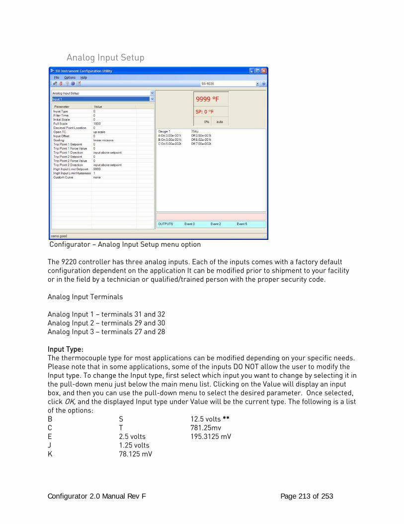
Configurator 2.0 Manual Rev F Page 213 of 253
Analog Input Setup
Configurator – Analog Input Setup menu option The 9220 controller has three analog inputs. Each of the inputs comes with a factory default configuration dependent on the application It can be modified prior to shipment to your facility or in the field by a technician or qualified/trained person with the proper security code. Analog Input Terminals Analog Input 1 – terminals 31 and 32 Analog Input 2 – terminals 29 and 30 Analog Input 3 – terminals 27 and 28 Input Type: The thermocouple type for most applications can be modified depending on your specific needs. Please note that in some applications, some of the inputs DO NOT allow the user to modify the Input type. To change the Input type, first select which input you want to change by selecting it in the pull-down menu just below the main menu list. Clicking on the Value will display an input box, and then you can use the pull-down menu to select the desired parameter. Once selected, click OK, and the displayed Input type under Value will be the current type. The following is a list of the options: B S 12.5 volts ** C T 781.25mv E 2.5 volts 195.3125 mV J 1.25 volts K 78.125 mV
Configurator 2.0 Manual Rev F Page 214 of 253
N 19.53125 mV NNM 4-20 mA ** R 25 volts ** ** - When the specified input type is selected, a jumper located inside the case will need to be placed on that specific input for reading this selection. If jumper is not placed on input, then damage could occur to the board. Filter time: The filter time is a factory applied averaging tool used to help maintain steady control in high EMI environments. The filter time should not be adjusted with consulting SSI. Clicking on this value will display an input box from which the user can select a new value. The range is 0 to 32767. Initial Scale: This is the initial scale value. Clicking on this value will display an input box from which the user can select a new value. The range is –32768 to 32767. Full scale: This is the full scale value. Clicking on this value will display an input box from which the user can select a new value. The range is –32768 to 32767. Decimal Point Location: This is the decimal point location value. Clicking on this value will display an input box from which the user can select a new value. The range is 0 to 4. Open TC: This is the open TC value. Clicking on this value will toggle between up scale, down scale, one trip point, and two trip points. Input Offset: The input offset value is algebraically added to the input value to adjust the input curve on read-out. The range is –10 to 10. Scaling: This is the scaling value. The options are: Linear Microns, Log Torr, or Auto Scale. Trip Point 1 Setpoint: This is the trip point 1 setpoint value. The range is –32768 to 32768. Trip Point 1 Force Value: This is the trip point 1 force value. The range is –32768 to 32768. Trip Point 1 Direction: This is the trip point 1 direction. The options are: input above setpoint or input below setpoint. Trip Point 2 Setpoint: This is the trip point 2 setpoint value. The range is –32768 to 32768.
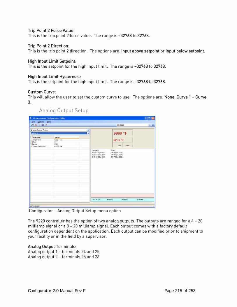
Configurator 2.0 Manual Rev F Page 215 of 253
Trip Point 2 Force Value: This is the trip point 2 force value. The range is –32768 to 32768. Trip Point 2 Direction: This is the trip point 2 direction. The options are: input above setpoint or input below setpoint. High Input Limit Setpoint: This is the setpoint for the high input limit. The range is –32768 to 32768. High Input Limit Hysteresis: This is the setpoint for the high input limit. The range is –32768 to 32768. Custom Curve: This will allow the user to set the custom curve to use. The options are: None, Curve 1 – Curve 3.
Analog Output Setup
Configurator – Analog Output Setup menu option The 9220 controller has the option of two analog outputs. The outputs are ranged for a 4 – 20 milliamp signal or a 0 – 20 milliamp signal. Each output comes with a factory default configuration dependent on the application. Each output can be modified prior to shipment to your facility or in the field by a supervisor. Analog Output Terminals: Analog output 1 – terminals 24 and 25 Analog output 2 – terminals 25 and 26
Configurator 2.0 Manual Rev F Page 216 of 253
Assignment: The analog output assignment can be modified depending on your system requirements. To change the Assignment first select which analog output you want to change by selecting it in the pull-down menu just below the main menu list. Clicking on this value will display an input box, and then you can use the pull-down menu to select the desired parameter. Once selected click OK and the displayed assignment under Value will be the current assignment type. The following is a list of the options: PV 1 retrans PV3 retrans G1 linear torr G4 log of torr Loop 1 inc Loop 3 inc G1 microns G4 linear torr Loop 1 dec Loop 3 dec G2 log of torr G4 microns Loop 1 combo Loop 3 combo G2 linear torr Programmer ID num PV 2 retrans Input 1 retrans G2 microns SP1 retrans Loop 2 inc Input 2 retrans G3 log of torr SP2 retrans Loop 2 dec Input 3 retrans G3 linear torr SP3 retrans Loop 2 combo G1 log of torr G3 microns Combo example for carbon – 4 – 12 mA Air 12 – 20 mA Gas Offset: This is the starting point, the Process Variable value at which you get 4 milliamps. Clicking on this value will display an input box from which the user can select a new value. The range is –32768 to 32767. Range: This is a Process Variable value between 4 and 20 milliamps. Clicking on this value will display an input box from which the user can select a new value. The range is –32768 to 32767. Current Selection: Provides the option of 4-20 mA or 0-20 mA control. Clicking on this value will display an input box with a drop-down list from which the user can select either of the two values listed above. Offset and Range when assigned to a control loop: Inc -- 0 = 4mA, 100 = 20mA Dec -- 0 = 4mA, -100 = 20mA Example: if 4 – 20 mA = 800 mV - 1200 mV Offset = 800 (starting point) Range = 400
Passcode and Alarm *** This menu option is the same as the Passcodes and Alarm menu option under the Configurator-9200 Drop Down Menu. ***
IP Address *** This menu option is the same as the IP Address menu option under the Configurator-9200 Drop Down Menu. ***
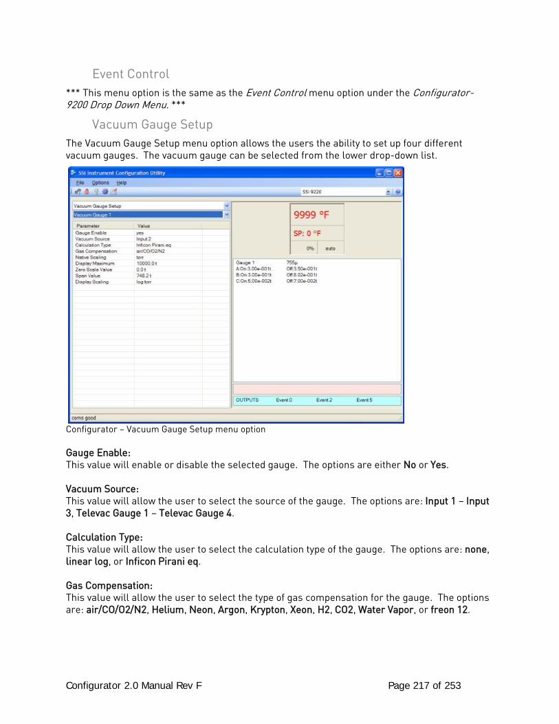
Configurator 2.0 Manual Rev F Page 217 of 253
Event Control *** This menu option is the same as the Event Control menu option under the Configurator-9200 Drop Down Menu. ***
Vacuum Gauge Setup The Vacuum Gauge Setup menu option allows the users the ability to set up four different vacuum gauges. The vacuum gauge can be selected from the lower drop-down list.
Configurator – Vacuum Gauge Setup menu option Gauge Enable: This value will enable or disable the selected gauge. The options are either No or Yes. Vacuum Source: This value will allow the user to select the source of the gauge. The options are: Input 1 – Input 3, Televac Gauge 1 – Televac Gauge 4. Calculation Type: This value will allow the user to select the calculation type of the gauge. The options are: none, linear log, or Inficon Pirani eq. Gas Compensation: This value will allow the user to select the type of gas compensation for the gauge. The options are: air/CO/O2/N2, Helium, Neon, Argon, Krypton, Xeon, H2, CO2, Water Vapor, or freon 12.
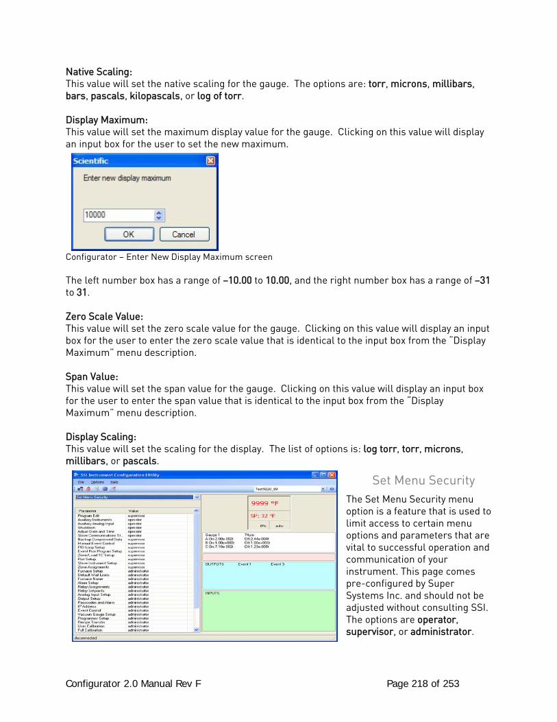
Configurator 2.0 Manual Rev F Page 218 of 253
Native Scaling: This value will set the native scaling for the gauge. The options are: torr, microns, millibars, bars, pascals, kilopascals, or log of torr. Display Maximum: This value will set the maximum display value for the gauge. Clicking on this value will display an input box for the user to set the new maximum.
Configurator – Enter New Display Maximum screen The left number box has a range of –10.00 to 10.00, and the right number box has a range of –31 to 31. Zero Scale Value: This value will set the zero scale value for the gauge. Clicking on this value will display an input box for the user to enter the zero scale value that is identical to the input box from the “Display Maximum” menu description. Span Value: This value will set the span value for the gauge. Clicking on this value will display an input box for the user to enter the span value that is identical to the input box from the “Display Maximum” menu description. Display Scaling: This value will set the scaling for the display. The list of options is: log torr, torr, microns, millibars, or pascals.
Set Menu Security The Set Menu Security menu option is a feature that is used to limit access to certain menu options and parameters that are vital to successful operation and communication of your instrument. This page comes pre-configured by Super Systems Inc. and should not be adjusted without consulting SSI. The options are operator, supervisor, or administrator.
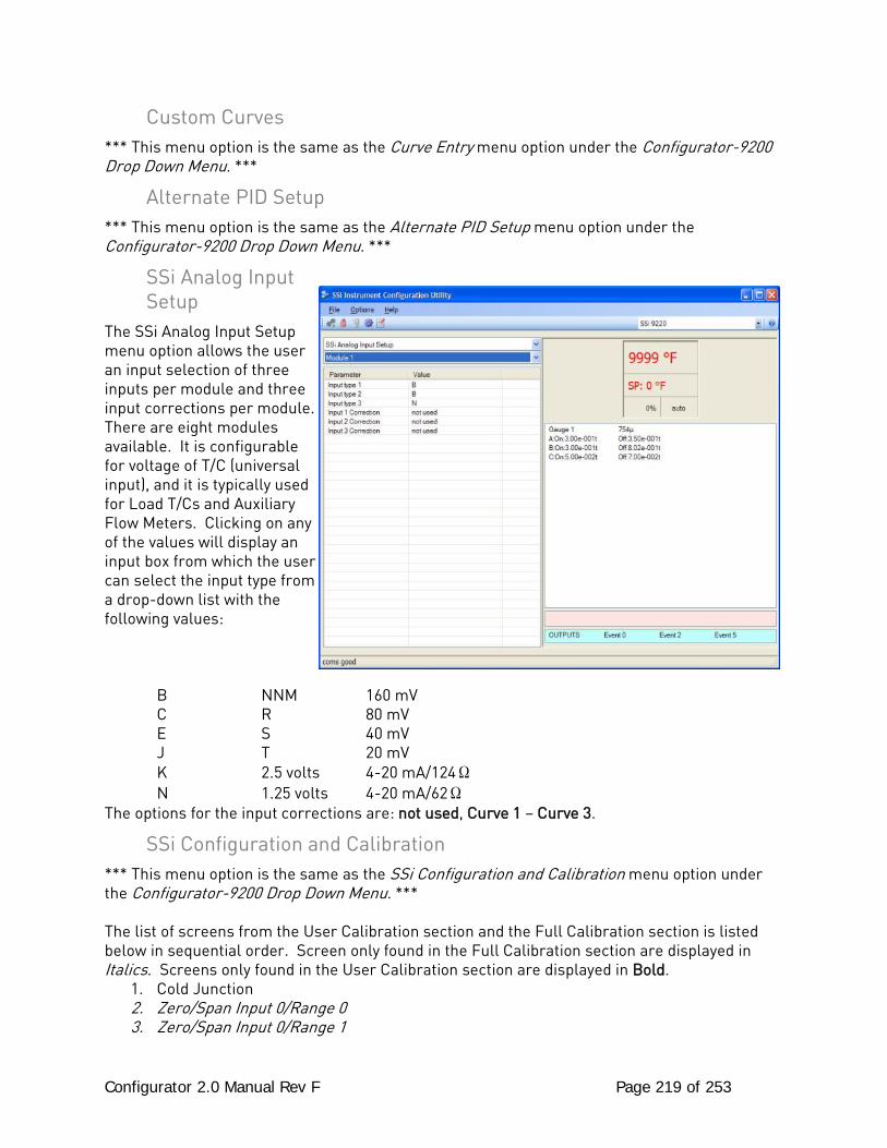
Configurator 2.0 Manual Rev F Page 219 of 253
Custom Curves *** This menu option is the same as the Curve Entry menu option under the Configurator-9200 Drop Down Menu. ***
Alternate PID Setup *** This menu option is the same as the Alternate PID Setup menu option under the Configurator-9200 Drop Down Menu. ***
SSi Analog Input Setup
The SSi Analog Input Setup menu option allows the user an input selection of three inputs per module and three input corrections per module. There are eight modules available. It is configurable for voltage of T/C (universal input), and it is typically used for Load T/Cs and Auxiliary Flow Meters. Clicking on any of the values will display an input box from which the user can select the input type from a drop-down list with the following values: B NNM 160 mV C R 80 mV E S 40 mV J T 20 mV K 2.5 volts 4-20 mA/124Ω N 1.25 volts 4-20 mA/62Ω The options for the input corrections are: not used, Curve 1 – Curve 3.
SSi Configuration and Calibration *** This menu option is the same as the SSi Configuration and Calibration menu option under the Configurator-9200 Drop Down Menu. *** The list of screens from the User Calibration section and the Full Calibration section is listed below in sequential order. Screen only found in the Full Calibration section are displayed in Italics. Screens only found in the User Calibration section are displayed in Bold.
1. Cold Junction 2. Zero/Span Input 0/Range 0 3. Zero/Span Input 0/Range 1
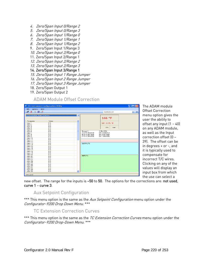
Configurator 2.0 Manual Rev F Page 220 of 253
4. Zero/Span Input 0/Range 2 5. Zero/Span Input 0/Range 3 6. Zero/Span Input 1/Range 0 7. Zero/Span Input 1/Range 1 8. Zero/Span Input 1/Range 2 9. Zero/Span Input 1/Range 3 10. Zero/Span Input 2/Range 0 11. Zero/Span Input 2/Range 1 12. Zero/Span Input 2/Range 2 13. Zero/Span Input 2/Range 3 14. Zero/Span Input 3/Range 1 15. Zero/Span Input 1 Range Jumper 16. Zero/Span Input 2 Range Jumper 17. Zero/Span Input 3 Range Jumper 18. Zero/Span Output 1 19. Zero/Span Output 2
ADAM Module Offset Correction The ADAM module Offset Correction menu option gives the user the ability to offset any input (1 – 40) on any ADAM module, as well as the Input correction offset (0 – 39). The offset can be in degrees + or -, and it is typically used to compensate for incorrect T/C wires. Clicking on any of the values will display an input box from which the use can select a
new offset. The range for the inputs is –50 to 50. The options for the corrections are: not used, curve 1 – curve 3.
Aux Setpoint Configuration *** This menu option is the same as the Aux Setpoint Configuration menu option under the Configurator-9200 Drop Down Menu. ***
TC Extension Correction Curves *** This menu option is the same as the TC Extension Correction Curves menu option under the Configurator-9200 Drop-Down Menu. ***
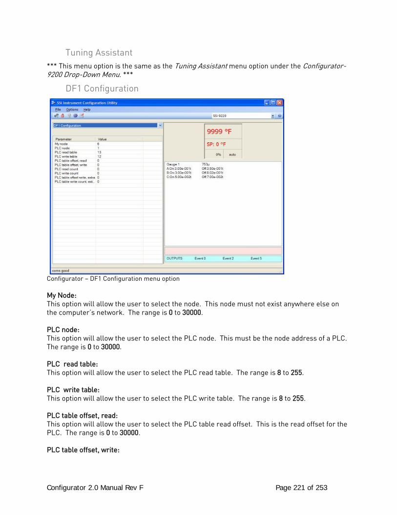
Configurator 2.0 Manual Rev F Page 221 of 253
Tuning Assistant *** This menu option is the same as the Tuning Assistant menu option under the Configurator-9200 Drop-Down Menu. ***
DF1 Configuration
Configurator – DF1 Configuration menu option My Node: This option will allow the user to select the node. This node must not exist anywhere else on the computer’s network. The range is 0 to 30000. PLC node: This option will allow the user to select the PLC node. This must be the node address of a PLC. The range is 0 to 30000. PLC read table: This option will allow the user to select the PLC read table. The range is 8 to 255. PLC write table: This option will allow the user to select the PLC write table. The range is 8 to 255. PLC table offset, read: This option will allow the user to select the PLC table read offset. This is the read offset for the PLC. The range is 0 to 30000. PLC table offset, write:

Configurator 2.0 Manual Rev F Page 222 of 253
This option will allow the user to select the PLC table write offset. This is the write offset for the PLC. The range is 0 to 30000. PLC read count: This option will allow the user to select the PLC read count. This will be the number of words to read from the PLC. The range is 0 to 30000. PLC write count: This option will allow the user to select the PLC write count. This will be the number of words to write to the PLC. The range is 0 to 30000. PLC table offset write, extra: This option will allow the user to select the PLC table write offset extra. This is the extra write offset for the PLC. The range is 0 to 30000. PLC table write count, extra: This option will allow the user to select the PLC table write count extra. This will be the number of extra words to write to the PLC. The range is 0 to 30000. Slave data mapping: This option will allow the user to select the object to map the PLC bitmap to. The user can select: Disabled, Slave Mapping Enabled, Loop Mapping Enabled, or Slave & Loop Mapping Enabled.
Configurator 2.0 Manual Rev F Page 223 of 253
Appendix A – Quench Control & Events The quench opcode starts a timer that is independent of any program running. Therefore, another program can be started while the quench is timing. When a load is transferred to quench manually by an operator, the program will have an end of cycle alarm that will alert the operator to transfer the load. When the operator acknowledges the alarm, the next step in the program will be the quench opcode. For automatic (PLC) applications, an end of cycle event output would be followed by an event input, which could be the inner door or other contact indicating the load was transferred. The next step is the quench opcode. The end of quench event is a one-second momentary output. Two or three events are used by the quench opcode. Quench speed hi/lo, which is specified in the option, and end of quench - the one-second pulse at the end of quench time - are always used. A quench run event that is active while the quench timer is running can be assigned. The Temperature is the quench temperature controller set point. The range is -301 (disable) – 30000. The Time is the quench time in minutes. The range is -1 (disable) – 9999. The Speed will control the agitator speed, high or low, by Event # 6 as a default. This event number can be changed in the furnace setup menu. This event will remain off if quench speed is set to low. It will turn on if the quench timer is timing and quench speed is set to high with the opcode. The quench temperature controller must be Aux Instrument # 4. The quench cycle starts when the opcode is executed. The set point is sent to the quench temperature controller, the timer is started, and the high-speed event is turned on if it is selected. Once the quench timer has timed out, the end of quench cycle event pulses on and off. The end of quench cycle is event 7 by default, but it can be changed within the furnace setup menu. The options are: Low or High. If the 9200 is also used for the quench temperature controller, the PVT type must be set to %C dual temperature. This uses input 1 for probe millivolts, input 2 for furnace temperature (also used for %C calculation), and input 3 for the quench temperature. Loop 1 is %C, loop 2 is furnace temperature, and loop 3 is quench temperature. The programmer would then have loop 3 assigned as the quench instrument
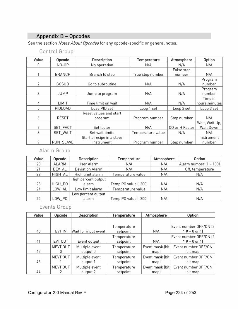
Configurator 2.0 Manual Rev F Page 224 of 253
Appendix B – Opcodes See the section Notes About Opcodes for any opcode-specific or general notes.
Control Group Value Opcode Description Temperature Atmosphere Option
0 NO-OP No operation N/A N/A N/A
1 BRANCH Branch to step True step number False step
number N/A
2 GOSUB Go to subroutine N/A N/A Program number
3 JUMP Jump to program N/A N/A Program number
4 LIMIT Time limit on wait N/A N/A Time in
hours:minutes 5 PIDLOAD Load PID set Loop 1 set Loop 2 set Loop 3 set
6 RESET Reset values and start
program Program number Step number N/A
7 SET_FACT Set factor N/A CO or H Factor Wait, Wait Up,
Wait Down 8 SET_WAIT Set wait limits Temperature value N/A N/A
9 RUN_SLAVE Start a recipe in a slave
instrument Program number Step number Instrument
number
Alarm Group Value Opcode Description Temperature Atmosphere Option
20 ALARM User Alarm N/A N/A Alarm number (1 – 100) 21 DEV_AL Deviation Alarm N/A N/A Off, temperature 22 HIGH_AL High limit alarm Temperature value N/A N/A
23 HIGH_PO High percent output
alarm Temp PO value (-200) N/A N/A 24 LOW_AL Low limit alarm Temperature value N/A N/A
25 LOW_PO Low percent output
alarm Temp PO value (-200) N/A N/A
Events Group Value Opcode Description Temperature Atmosphere Option
40 EVT IN Wait for input event Temperature
setpoint N/A Event number OFF/ON (2
* # + 0 or 1)
41 EVT OUT Event output Temperature
setpoint N/A Event number OFF/ON (2
* # + 0 or 1)
42 MEVT OUT
0 Multiple event
output 0 Temperature
setpoint Event mask (bit
map) Event number OFF/ON
bit map
43 MEVT OUT
1 Multiple event
output 1 Temperature
setpoint Event mask (bit
map) Event number OFF/ON
bit map
44 MEVT OUT
2 Multiple event
output 2 Temperature
setpoint Event mask (bit
map) Event number OFF/ON
bit map
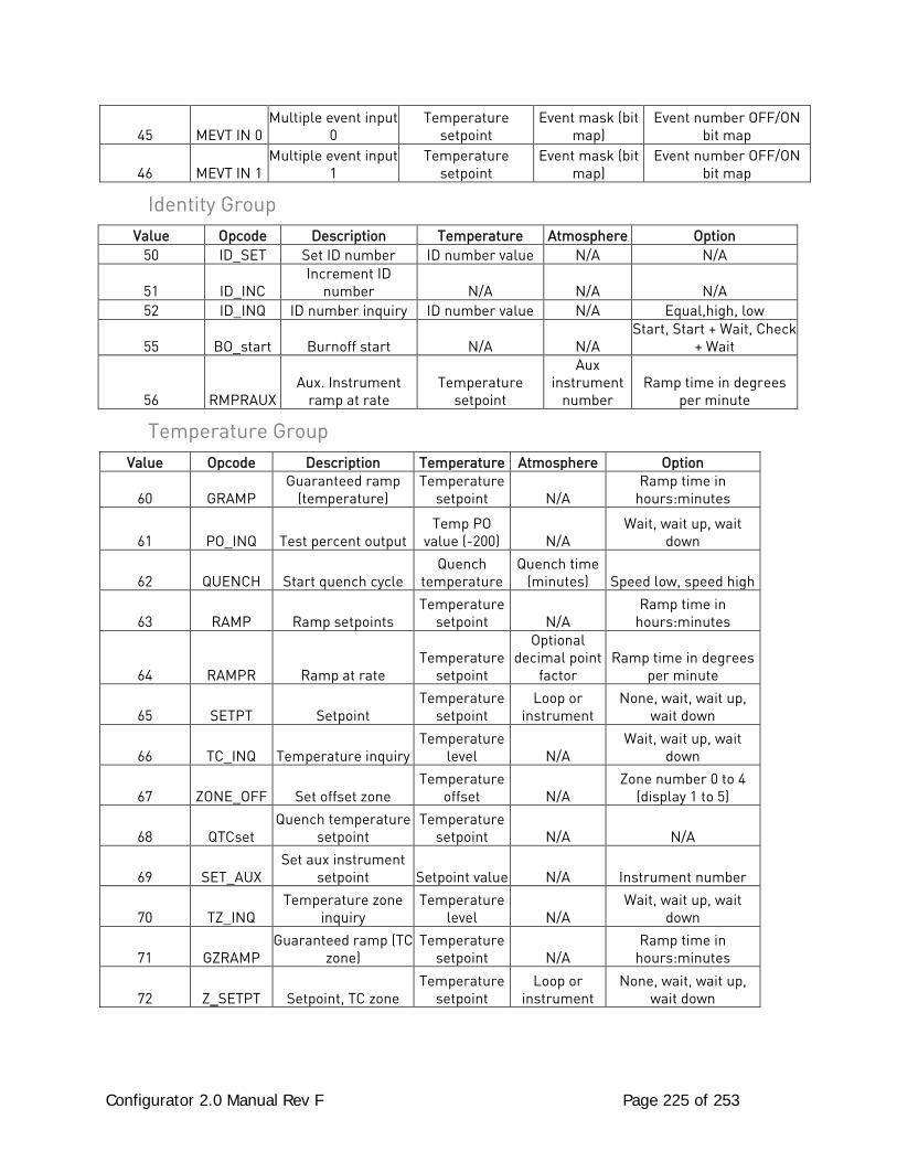
Configurator 2.0 Manual Rev F Page 225 of 253
45 MEVT IN 0 Multiple event input
0 Temperature
setpoint Event mask (bit
map) Event number OFF/ON
bit map
46 MEVT IN 1 Multiple event input
1 Temperature
setpoint Event mask (bit
map) Event number OFF/ON
bit map
Identity Group Value Opcode Description Temperature Atmosphere Option
50 ID_SET Set ID number ID number value N/A N/A
51 ID_INC Increment ID
number N/A N/A N/A 52 ID_INQ ID number inquiry ID number value N/A Equal,high, low
55 BO_start Burnoff start N/A N/A Start, Start + Wait, Check
+ Wait
56 RMPRAUX Aux. Instrument
ramp at rate Temperature
setpoint
Aux instrument
number Ramp time in degrees
per minute
Temperature Group Value Opcode Description Temperature Atmosphere Option
60 GRAMP Guaranteed ramp
(temperature) Temperature
setpoint N/A Ramp time in
hours:minutes
61 PO_INQ Test percent output Temp PO
value (-200) N/A Wait, wait up, wait
down
62 QUENCH Start quench cycle Quench
temperature Quench time
(minutes) Speed low, speed high
63 RAMP Ramp setpoints Temperature
setpoint N/A Ramp time in
hours:minutes
64 RAMPR Ramp at rate Temperature
setpoint
Optional decimal point
factor Ramp time in degrees
per minute
65 SETPT Setpoint Temperature
setpoint Loop or
instrument None, wait, wait up,
wait down
66 TC_INQ Temperature inquiry Temperature
level N/A Wait, wait up, wait
down
67 ZONE_OFF Set offset zone Temperature
offset N/A Zone number 0 to 4
(display 1 to 5)
68 QTCset Quench temperature
setpoint Temperature
setpoint N/A N/A
69 SET_AUX Set aux instrument
setpoint Setpoint value N/A Instrument number
70 TZ_INQ Temperature zone
inquiry Temperature
level N/A Wait, wait up, wait
down
71 GZRAMP Guaranteed ramp (TC
zone) Temperature
setpoint N/A Ramp time in
hours:minutes
72 Z_SETPT Setpoint, TC zone Temperature
setpoint Loop or
instrument None, wait, wait up,
wait down
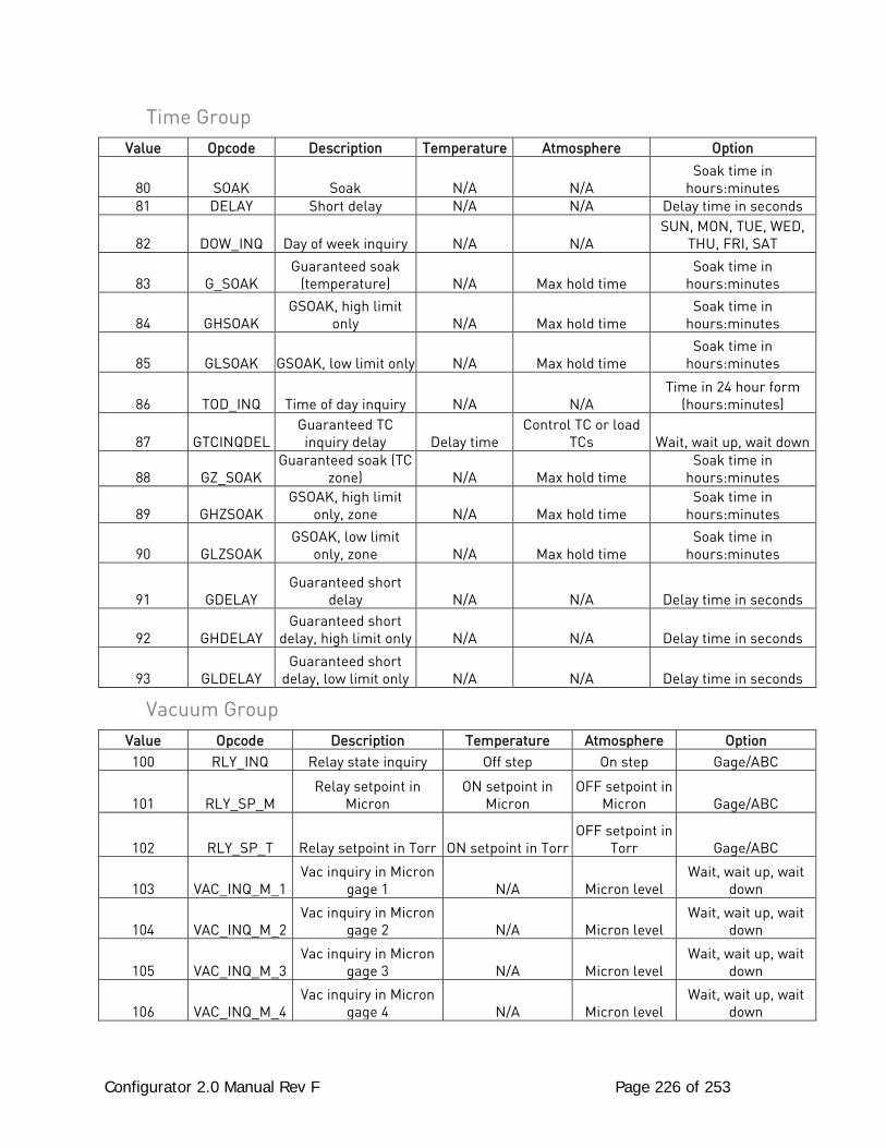
Configurator 2.0 Manual Rev F Page 226 of 253
Time Group Value Opcode Description Temperature Atmosphere Option
80 SOAK Soak N/A N/A Soak time in
hours:minutes 81 DELAY Short delay N/A N/A Delay time in seconds
82 DOW_INQ Day of week inquiry N/A N/A SUN, MON, TUE, WED,
THU, FRI, SAT
83 G_SOAK Guaranteed soak
(temperature) N/A Max hold time Soak time in
hours:minutes
84 GHSOAK GSOAK, high limit
only N/A Max hold time Soak time in
hours:minutes
85 GLSOAK GSOAK, low limit only N/A Max hold time Soak time in
hours:minutes
86 TOD_INQ Time of day inquiry N/A N/A Time in 24 hour form
(hours:minutes)
87 GTCINQDEL Guaranteed TC inquiry delay Delay time
Control TC or load TCs Wait, wait up, wait down
88 GZ_SOAK Guaranteed soak (TC
zone) N/A Max hold time Soak time in
hours:minutes
89 GHZSOAK GSOAK, high limit
only, zone N/A Max hold time Soak time in
hours:minutes
90 GLZSOAK GSOAK, low limit
only, zone N/A Max hold time Soak time in
hours:minutes
91 GDELAY Guaranteed short
delay N/A N/A Delay time in seconds
92 GHDELAY Guaranteed short
delay, high limit only N/A N/A Delay time in seconds
93 GLDELAY Guaranteed short
delay, low limit only N/A N/A Delay time in seconds
Vacuum Group Value Opcode Description Temperature Atmosphere Option 100 RLY_INQ Relay state inquiry Off step On step Gage/ABC
101 RLY_SP_M Relay setpoint in
Micron ON setpoint in
Micron OFF setpoint in
Micron Gage/ABC
102 RLY_SP_T Relay setpoint in Torr ON setpoint in Torr OFF setpoint in
Torr Gage/ABC
103 VAC_INQ_M_1 Vac inquiry in Micron
gage 1 N/A Micron level Wait, wait up, wait
down
104 VAC_INQ_M_2 Vac inquiry in Micron
gage 2 N/A Micron level Wait, wait up, wait
down
105 VAC_INQ_M_3 Vac inquiry in Micron
gage 3 N/A Micron level Wait, wait up, wait
down
106 VAC_INQ_M_4 Vac inquiry in Micron
gage 4 N/A Micron level Wait, wait up, wait
down
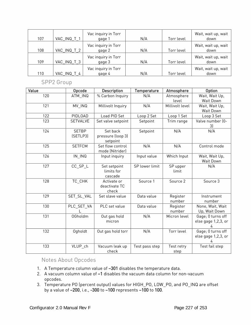
Configurator 2.0 Manual Rev F Page 227 of 253
107 VAC_INQ_T_1 Vac inquiry in Torr
gage 1 N/A Torr level Wait, wait up, wait
down
108 VAC_INQ_T_2 Vac inquiry in Torr
gage 2 N/A Torr level Wait, wait up, wait
down
109 VAC_INQ_T_3 Vac inquiry in Torr
gage 3 N/A Torr level Wait, wait up, wait
down
110 VAC_INQ_T_4 Vac inquiry in Torr
gage 4 N/A Torr level Wait, wait up, wait
down
SPP2 Group Value Opcode Description Temperature Atmosphere Option
120 ATM_INQ % Carbon Inquiry N/A Atmosphere level
Wait, Wait Up, Wait Down
121 MV_INQ Millivolt Inquiry N/A Millivolt level Wait, Wait Up, Wait Down
122 PIDLOAD Load PID Set Loop 2 Set Loop 1 Set Loop 3 Set 123 SETVALVE Set valve setpoint Setpoint Trim range Valve number (0-
3) 124 SETBP
(SETLP3) Set back
pressure (loop 3) setpoint
Setpoint N/A N/A
125 SETFCM Set flow control mode (Nitrider)
N/A N/A Control mode
126 IN_INQ Input inquiry Input value Which Input Wait, Wait Up, Wait Down
127 CC_SP_L Set setpoint limits for cascade
SP lower limit SP upper limit
N/A
128 TC_CHK Activate or deactivate TC
check
Source 1 Source 2 Source 3
129 SET_SL_VAL Set slave value Data value Register number
Instrument number
130 PLC_SET_VAL
PLC set value Data value Register number
None, Wait, Wait Up, Wait Down
131 OGholdm Out gas hold micron
N/A Micron level Gage; 0 turns off else gage 1,2,3, or
4 132 Ogholdt Out gas hold torr N/A Torr level Gage; 0 turns off
else gage 1,2,3, or 4
133 VLUP_ch Vacuum leak up check
Test pass step Test retry step
Test fail step
Notes About Opcodes 1. A Temperature column value of –301 disables the temperature data. 2. A vacuum column value of –1 disables the vacuum data column for non-vacuum
opcodes. 3. Temperature PO (percent output) values for HIGH_PO, LOW_PO, and PO_INQ are offset
by a value of –200, i.e., -300 to –100 represents –100 to 100.
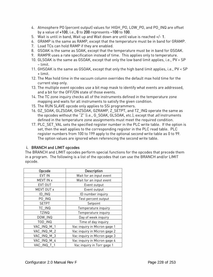
Configurator 2.0 Manual Rev F Page 228 of 253
4. Atmosphere PO (percent output) values for HIGH_PO, LOW_PO, and PO_INQ are offset by a value of +100, i.e., 0 to 200 represents –100 to 100.
5. Wait is until in band, Wait up and Wait down are until value is reached +/- 1. 6. GRAMP is the same as RAMP, except that the temperature must be in band for GRAMP. 7. Load TCs can hold RAMP if they are enabled. 8. GSOAK is the same as SOAK, except that the temperature must be in band for GSOAK. 9. RAMPR uses a rate specification instead of time. This applies only to temperature. 10. GLSOAK is the same as GSOAK, except that only the low band limit applies, i.e., PV > SP
– limit. 11. GHSOAK is the same as GSOAK, except that only the high band limit applies, i.e., PV < SP
+ limit. 12. The Max hold time in the vacuum column overrides the default max hold time for the
current step only. 13. The multiple event opcodes use a bit map mask to identify what events are addressed,
and a bit for the OFF/ON state of those events. 14. The TC zone inquiry checks all of the instruments defined in the temperature zone
mapping and waits for all instruments to satisfy the given condition. 15. The RUN SLAVE opcode only applies to SSi programmers. 16. GZ_SOAK, GLZSOAK, GHZSOAK, GZRAMP, Z_SETPT, and TZ_INQ operate the same as
the opcodes without the “Z” (i.e., G_SOAK, GLSOAK, etc.), except that all instruments defined in the temperature zone assignments must meet the required condition.
17. PLC_SET_VAL sets the specified register number in the PLC write table. If the option is set, then the wait applies to the corresponding register in the PLC read table. PLC register numbers from 100 to 199 apply to the optional second write table as 0 to 99. The option values are ignored when referencing the second write table.
i. BRANCH and LIMIT opcodes
The BRANCH and LIMIT opcodes perform special functions for the opcodes that precede them in a program. The following is a list of the opcodes that can use the BRANCH and/or LIMIT opcode.
Opcode Description EVT IN Wait for an input event
MEVT IN x Wait for an input event EVT OUT Event output
MEVT OUT x Event output ID_INQ ID number inquiry PO_INQ Test percent output SETPT Setpoint TC_INQ Temperature inquiry TZINQ Temperature inquiry
DOW_INQ Day of week inquiry TOD_INQ Time of day inquiry
VAC_INQ_M_1 Vac inquiry in Micron gage 1 VAC_INQ_M_2 Vac inquiry in Micron gage 2 VAC_INQ_M_3 Vac inquiry in Micron gage 3 VAC_INQ_M_4 Vac inquiry in Micron gage 4 VAC_INQ_T_1 Vac inquiry in Torr gage 1
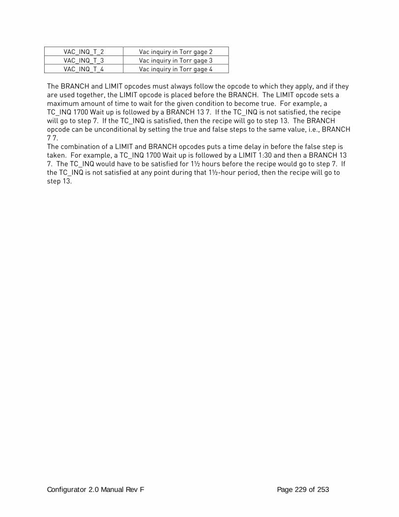
Configurator 2.0 Manual Rev F Page 229 of 253
VAC_INQ_T_2 Vac inquiry in Torr gage 2 VAC_INQ_T_3 Vac inquiry in Torr gage 3 VAC_INQ_T_4 Vac inquiry in Torr gage 4
The BRANCH and LIMIT opcodes must always follow the opcode to which they apply, and if they are used together, the LIMIT opcode is placed before the BRANCH. The LIMIT opcode sets a maximum amount of time to wait for the given condition to become true. For example, a TC_INQ 1700 Wait up is followed by a BRANCH 13 7. If the TC_INQ is not satisfied, the recipe will go to step 7. If the TC_INQ is satisfied, then the recipe will go to step 13. The BRANCH opcode can be unconditional by setting the true and false steps to the same value, i.e., BRANCH 7 7. The combination of a LIMIT and BRANCH opcodes puts a time delay in before the false step is taken. For example, a TC_INQ 1700 Wait up is followed by a LIMIT 1:30 and then a BRANCH 13 7. The TC_INQ would have to be satisfied for 1½ hours before the recipe would go to step 7. If the TC_INQ is not satisfied at any point during that 1½-hour period, then the recipe will go to step 13.

Configurator 2.0 Manual Rev F Page 230 of 253
Appendix C - Programmer Alarms The programmer alarm provides the ability to trigger specific alarms when a program is running. They can be user defined alarms ranging from Programmer Alarm 1-99 or be specific alarms occurring during the program. User defined programmer alarms are entered using the User Alarm op-code in a recipe. A list of the process-related programmer alarms is listed below. User Alarm 0 is not an alarm; it is used to turn off a user alarm. It functions the same way as the acknowledge button.
Alarm Code User Alarm 100 Atmosphere Deviation 101 High Atmosphere 102 Low Atmosphere 103 Temperature Deviation 104 High Temperature 105 Low Temperature 106 High Atmosphere % Output 107 Low Atmosphere % Output 108 High Temperature % Output 109 High Temperature % Output 110 Gosub Error 111 Limit Alarm 112 Recipe Hold Alarm 115 Bad PID Values 125
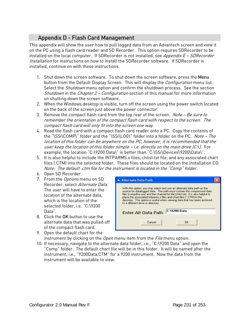
Configurator 2.0 Manual Rev F Page 231 of 253
Appendix D - Flash Card Management This appendix will show the user how to pull logged data from an Advantech screen and view it on the PC using a flash card reader and SD Recorder. This option requires SDRecorder to be installed on the local computer. If SDRecorder is not installed, see Appendix E – SDRecorder Installation for instructions on how to install the SDRecorder software. If SDRecorder is installed, continue on with these instructions.
1. Shut down the screen software. To shut down the screen software, press the Menu button from the Default Display Screen. This will display the Configuration menu list. Select the Shutdown menu option and confirm the shutdown process. See the section Shutdown in the Chapter 2 – Configuration section of this manual for more information on shutting down the screen software.
2. When the Windows desktop is visible, turn off the screen using the power switch located on the back of the screen just above the power connector.
3. Remove the compact flash card from the top rear of the screen. Note – Be sure to remember the orientation of the compact flash card with respect to the screen. The compact flash card will only fit into the screen one way.
4. Read the flash card with a compact flash card reader onto a PC. Copy the contents of the “\SSi\COMP\” folder and the “\SSi\LOG\” folder into a folder on the PC. Note – The location of this folder can be anywhere on the PC, however, it is recommended that the user keep the location of this folder simple – i.e. directly on the main drive (C:\). For example, the location “C:\9200 Data\” is better than “C:\SSi\Devices\9200\Data\”.
5. It is also helpful to include the INTPARMS.x files, chlist.txt file, and any associated chart files (.CTM) into the selected folder. These files should be located on the installation CD. Note: The default .ctm file for the instrument is located in the “Comp” folder.
6. Open SD Recorder. 7. From the Options menu on SD
Recorder, select Alternate Data. The user will have to enter the location of the alternate data, which is the location of the selected folder, i.e. “C:\9200 Data”.
8. Click the OK button to use the alternate data that was pulled off of the compact flash card.
9. Open the default chart for the instrument by clicking on the Open menu item from the File menu option.
10. If necessary, navigate to the alternate data folder, i.e., “C:\9200 Data” and open the “Comp” folder. The default chart file will be in this folder. It will be named after the instrument, i.e., “9200Data.CTM” for a 9200 instrument. Now the data from the instrument will be available to view.
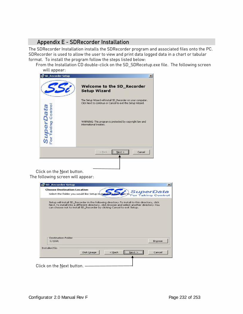
Configurator 2.0 Manual Rev F Page 232 of 253
Appendix E - SDRecorder Installation The SDRecorder Installation installs the SDRecorder program and associated files onto the PC. SDRecorder is used to allow the user to view and print data logged data in a chart or tabular format. To install the program follow the steps listed below:
From the Installation CD double-click on the SD_SDRecetup.exe file. The following screen will appear:
Click on the Next button.
The following screen will appear:
Click on the Next button.
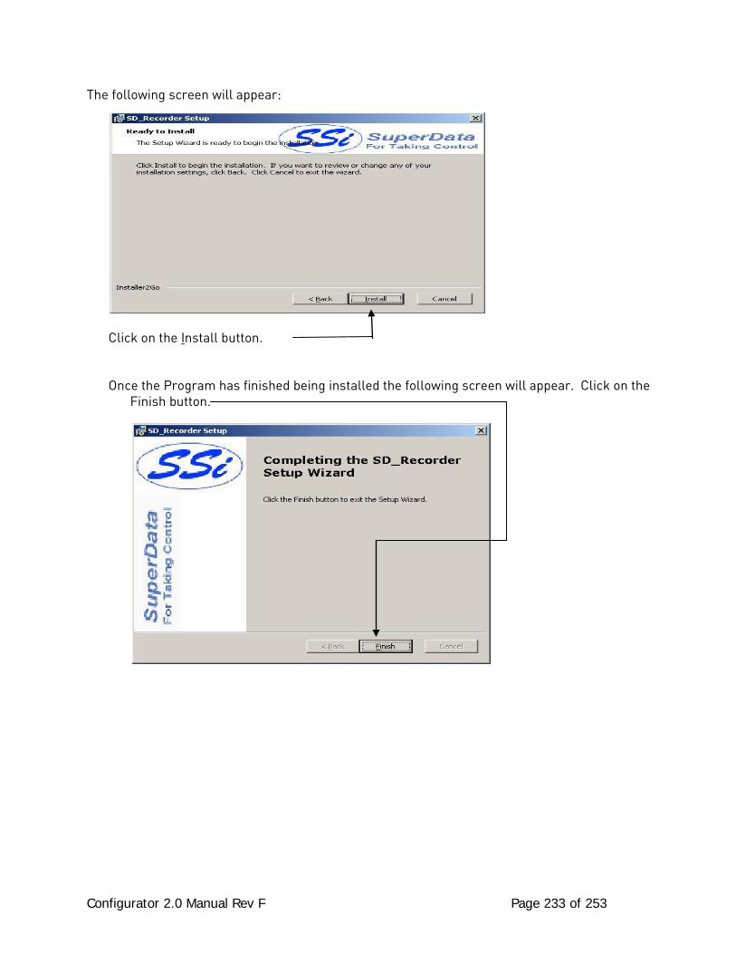
Configurator 2.0 Manual Rev F Page 233 of 253
The following screen will appear:
Click on the Install button.
Once the Program has finished being installed the following screen will appear. Click on the Finish button.
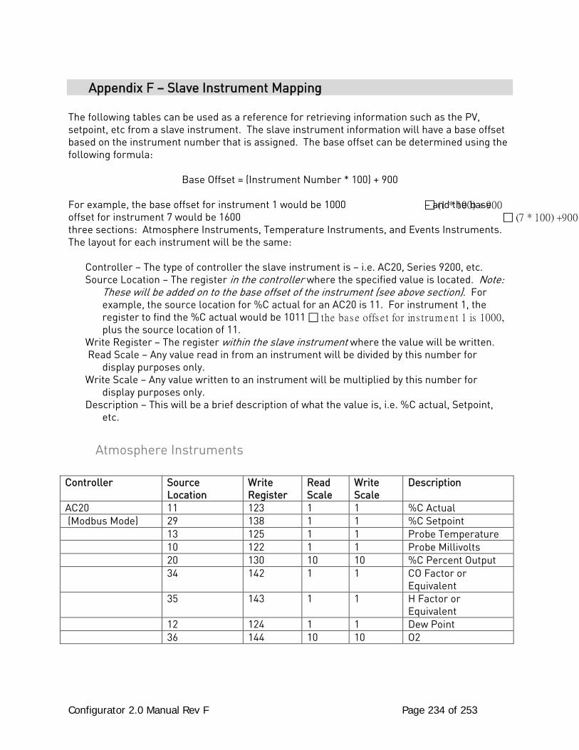
Configurator 2.0 Manual Rev F Page 234 of 253
Appendix F – Slave Instrument Mapping The following tables can be used as a reference for retrieving information such as the PV, setpoint, etc from a slave instrument. The slave instrument information will have a base offset based on the instrument number that is assigned. The base offset can be determined using the following formula:
Base Offset = (Instrument Number * 100) + 900
For example, the base offset for instrument 1 would be 1000 (1 * 100) + 900 – and the base offset for instrument 7 would be 1600 (7 * 100) +900. three sections: Atmosphere Instruments, Temperature Instruments, and Events Instruments. The layout for each instrument will be the same:
Controller – The type of controller the slave instrument is – i.e. AC20, Series 9200, etc. Source Location – The register in the controller where the specified value is located. Note:
These will be added on to the base offset of the instrument (see above section). For example, the source location for %C actual for an AC20 is 11. For instrument 1, the register to find the %C actual would be 1011 the bas e offs e t for ins trum ent 1 is 1000, plus the source location of 11.
Write Register – The register within the slave instrument where the value will be written. Read Scale – Any value read in from an instrument will be divided by this number for
display purposes only. Write Scale – Any value written to an instrument will be multiplied by this number for
display purposes only. Description – This will be a brief description of what the value is, i.e. %C actual, Setpoint,
etc.
Atmosphere Instruments
Controller Source Location
Write Register
Read Scale
Write Scale
Description
AC20 11 123 1 1 %C Actual (Modbus Mode) 29 138 1 1 %C Setpoint 13 125 1 1 Probe Temperature 10 122 1 1 Probe Millivolts 20 130 10 10 %C Percent Output 34 142 1 1 CO Factor or
Equivalent 35 143 1 1 H Factor or
Equivalent 12 124 1 1 Dew Point 36 144 10 10 O2
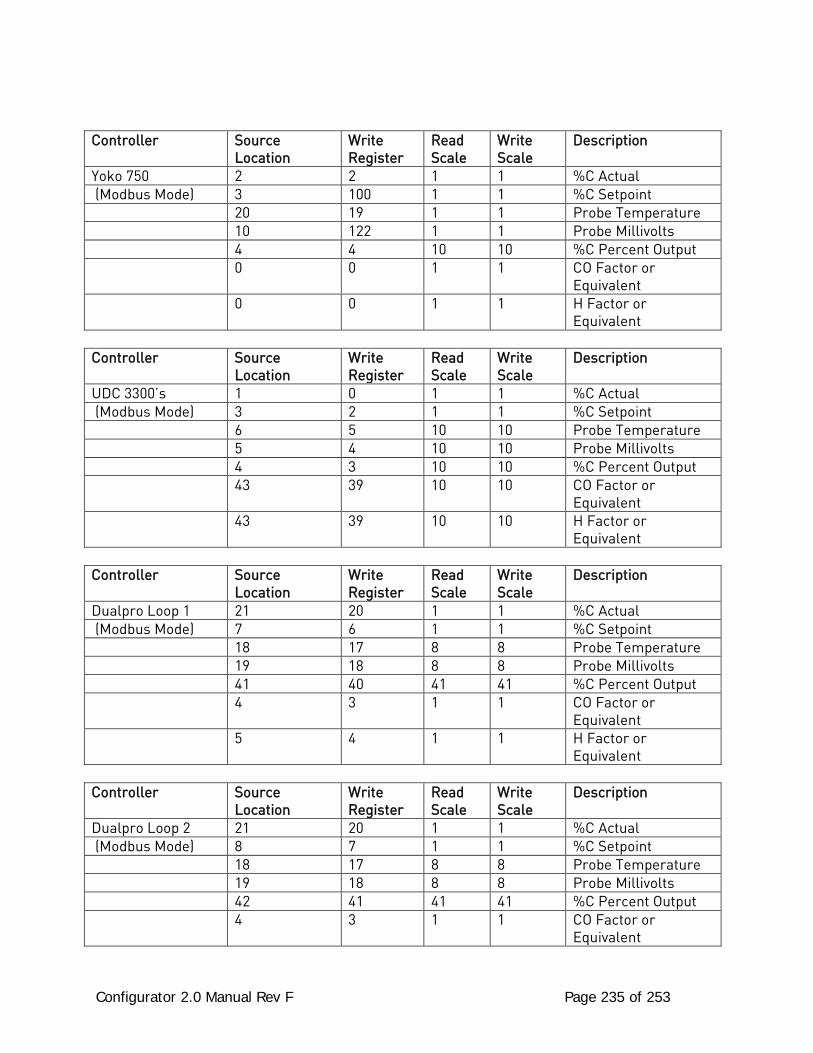
Configurator 2.0 Manual Rev F Page 235 of 253
Controller Source Location
Write Register
Read Scale
Write Scale
Description
Yoko 750 2 2 1 1 %C Actual (Modbus Mode) 3 100 1 1 %C Setpoint 20 19 1 1 Probe Temperature 10 122 1 1 Probe Millivolts 4 4 10 10 %C Percent Output 0 0 1 1 CO Factor or
Equivalent 0 0 1 1 H Factor or
Equivalent
Controller Source Location
Write Register
Read Scale
Write Scale
Description
UDC 3300’s 1 0 1 1 %C Actual (Modbus Mode) 3 2 1 1 %C Setpoint 6 5 10 10 Probe Temperature 5 4 10 10 Probe Millivolts 4 3 10 10 %C Percent Output 43 39 10 10 CO Factor or
Equivalent 43 39 10 10 H Factor or
Equivalent
Controller Source Location
Write Register
Read Scale
Write Scale
Description
Dualpro Loop 1 21 20 1 1 %C Actual (Modbus Mode) 7 6 1 1 %C Setpoint 18 17 8 8 Probe Temperature 19 18 8 8 Probe Millivolts 41 40 41 41 %C Percent Output 4 3 1 1 CO Factor or
Equivalent 5 4 1 1 H Factor or
Equivalent
Controller Source Location
Write Register
Read Scale
Write Scale
Description
Dualpro Loop 2 21 20 1 1 %C Actual (Modbus Mode) 8 7 1 1 %C Setpoint 18 17 8 8 Probe Temperature 19 18 8 8 Probe Millivolts 42 41 41 41 %C Percent Output 4 3 1 1 CO Factor or
Equivalent
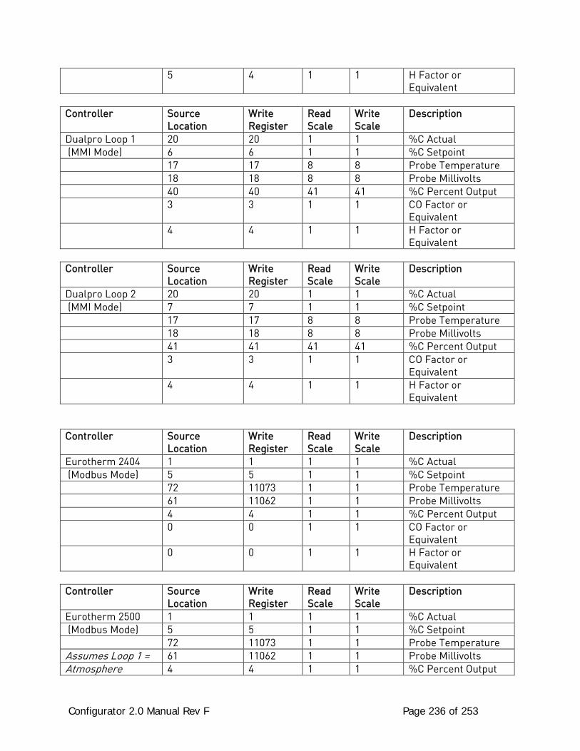
Configurator 2.0 Manual Rev F Page 236 of 253
5 4 1 1 H Factor or Equivalent
Controller Source
Location Write Register
Read Scale
Write Scale
Description
Dualpro Loop 1 20 20 1 1 %C Actual (MMI Mode) 6 6 1 1 %C Setpoint 17 17 8 8 Probe Temperature 18 18 8 8 Probe Millivolts 40 40 41 41 %C Percent Output 3 3 1 1 CO Factor or
Equivalent 4 4 1 1 H Factor or
Equivalent
Controller Source Location
Write Register
Read Scale
Write Scale
Description
Dualpro Loop 2 20 20 1 1 %C Actual (MMI Mode) 7 7 1 1 %C Setpoint 17 17 8 8 Probe Temperature 18 18 8 8 Probe Millivolts 41 41 41 41 %C Percent Output 3 3 1 1 CO Factor or
Equivalent 4 4 1 1 H Factor or
Equivalent
Controller Source Location
Write Register
Read Scale
Write Scale
Description
Eurotherm 2404 1 1 1 1 %C Actual (Modbus Mode) 5 5 1 1 %C Setpoint 72 11073 1 1 Probe Temperature 61 11062 1 1 Probe Millivolts 4 4 1 1 %C Percent Output 0 0 1 1 CO Factor or
Equivalent 0 0 1 1 H Factor or
Equivalent
Controller Source Location
Write Register
Read Scale
Write Scale
Description
Eurotherm 2500 1 1 1 1 %C Actual (Modbus Mode) 5 5 1 1 %C Setpoint 72 11073 1 1 Probe Temperature Assumes Loop 1 = 61 11062 1 1 Probe Millivolts Atmosphere 4 4 1 1 %C Percent Output
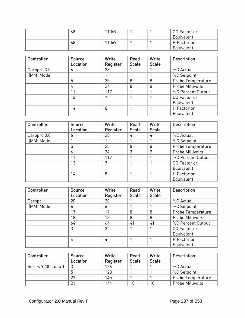
Configurator 2.0 Manual Rev F Page 237 of 253
68 11069 1 1 CO Factor or Equivalent
68 11069 1 1 H Factor or Equivalent
Controller Source
Location Write Register
Read Scale
Write Scale
Description
Carbpro 3.5 6 28 1 1 %C Actual (MMI Mode) 1 1 1 1 %C Setpoint 5 25 8 8 Probe Temperature 4 24 8 8 Probe Millivolts 11 117 1 1 %C Percent Output 13 7 1 1 CO Factor or
Equivalent 14 8 1 1 H Factor or
Equivalent
Controller Source Location
Write Register
Read Scale
Write Scale
Description
Carbpro 3.0 6 28 4 4 %C Actual (MMI Mode) 1 1 1 1 %C Setpoint 5 25 8 8 Probe Temperature 4 24 2 2 Probe Millivolts 11 117 1 1 %C Percent Output 13 7 1 1 CO Factor or
Equivalent 14 8 1 1 H Factor or
Equivalent
Controller Source Location
Write Register
Read Scale
Write Scale
Description
Carbpc 20 20 1 1 %C Actual (MMI Mode) 6 6 1 1 %C Setpoint 17 17 8 8 Probe Temperature 18 18 8 8 Probe Millivolts 64 64 41 41 %C Percent Output 3 3 1 1 CO Factor or
Equivalent 4 4 1 1 H Factor or
Equivalent
Controller Source Location
Write Register
Read Scale
Write Scale
Description
Series 9200 Loop 1 3 126 1 1 %C Actual 5 128 1 1 %C Setpoint 22 145 1 1 Probe Temperature 21 144 10 10 Probe Millivolts
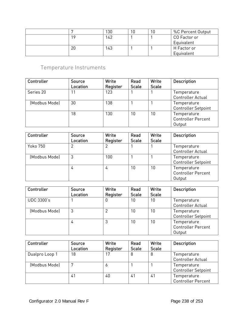
Configurator 2.0 Manual Rev F Page 238 of 253
7 130 10 10 %C Percent Output 19 142 1 1 CO Factor or
Equivalent 20 143 1 1 H Factor or
Equivalent
Temperature Instruments
Controller Source Location
Write Register
Read Scale
Write Scale
Description
Series 20 11 123 1 1 Temperature Controller Actual
(Modbus Mode) 30 138 1 1 Temperature Controller Setpoint
18 130 10 10 Temperature Controller Percent Output
Controller Source
Location Write Register
Read Scale
Write Scale
Description
Yoko 750 2 2 1 1 Temperature Controller Actual
(Modbus Mode) 3 100 1 1 Temperature Controller Setpoint
4 4 10 10 Temperature Controller Percent Output
Controller Source
Location Write Register
Read Scale
Write Scale
Description
UDC 3300’s 1 0 10 10 Temperature Controller Actual
(Modbus Mode) 3 2 10 10 Temperature Controller Setpoint
4 3 10 10 Temperature Controller Percent Output
Controller Source
Location Write Register
Read Scale
Write Scale
Description
Dualpro Loop 1 18 17 8 8 Temperature Controller Actual
(Modbus Mode) 7 6 1 1 Temperature Controller Setpoint
41 40 41 41 Temperature Controller Percent
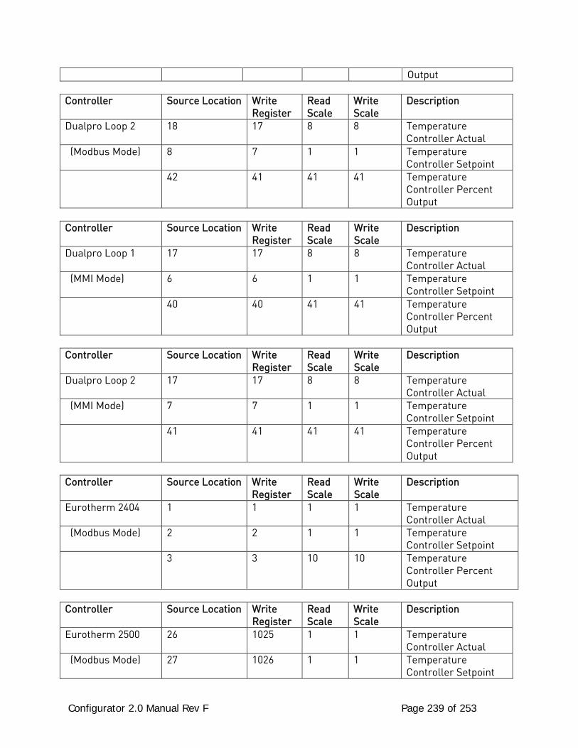
Configurator 2.0 Manual Rev F Page 239 of 253
Output
Controller Source Location Write Register
Read Scale
Write Scale
Description
Dualpro Loop 2 18 17 8 8 Temperature Controller Actual
(Modbus Mode) 8 7 1 1 Temperature Controller Setpoint
42 41 41 41 Temperature Controller Percent Output
Controller Source Location Write
Register Read Scale
Write Scale
Description
Dualpro Loop 1 17 17 8 8 Temperature Controller Actual
(MMI Mode) 6 6 1 1 Temperature Controller Setpoint
40 40 41 41 Temperature Controller Percent Output
Controller Source Location Write
Register Read Scale
Write Scale
Description
Dualpro Loop 2 17 17 8 8 Temperature Controller Actual
(MMI Mode) 7 7 1 1 Temperature Controller Setpoint
41 41 41 41 Temperature Controller Percent Output
Controller Source Location Write
Register Read Scale
Write Scale
Description
Eurotherm 2404 1 1 1 1 Temperature Controller Actual
(Modbus Mode) 2 2 1 1 Temperature Controller Setpoint
3 3 10 10 Temperature Controller Percent Output
Controller Source Location Write
Register Read Scale
Write Scale
Description
Eurotherm 2500 26 1025 1 1 Temperature Controller Actual
(Modbus Mode) 27 1026 1 1 Temperature Controller Setpoint
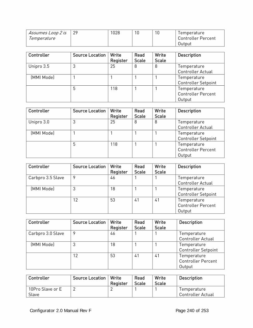
Configurator 2.0 Manual Rev F Page 240 of 253
Assumes Loop 2 is Temperature
29 1028 10 10 Temperature Controller Percent Output
Controller Source Location Write
Register Read Scale
Write Scale
Description
Unipro 3.5 3 25 8 8 Temperature Controller Actual
(MMI Mode) 1 1 1 1 Temperature Controller Setpoint
5 118 1 1 Temperature Controller Percent Output
Controller Source Location Write
Register Read Scale
Write Scale
Description
Unipro 3.0 3 25 8 8 Temperature Controller Actual
(MMI Mode) 1 1 1 1 Temperature Controller Setpoint
5 118 1 1 Temperature Controller Percent Output
Controller Source Location Write
Register Read Scale
Write Scale
Description
Carbpro 3.5 Slave 9 46 1 1 Temperature Controller Actual
(MMI Mode) 3 18 1 1 Temperature Controller Setpoint
12 53 41 41 Temperature Controller Percent Output
Controller Source Location Write
Register Read Scale
Write Scale
Description
Carbpro 3.0 Slave 9 46 1 1 Temperature Controller Actual
(MMI Mode) 3 18 1 1 Temperature Controller Setpoint
12 53 41 41 Temperature Controller Percent Output
Controller Source Location Write
Register Read Scale
Write Scale
Description
10Pro Slave or E Slave
2 2 1 1 Temperature Controller Actual
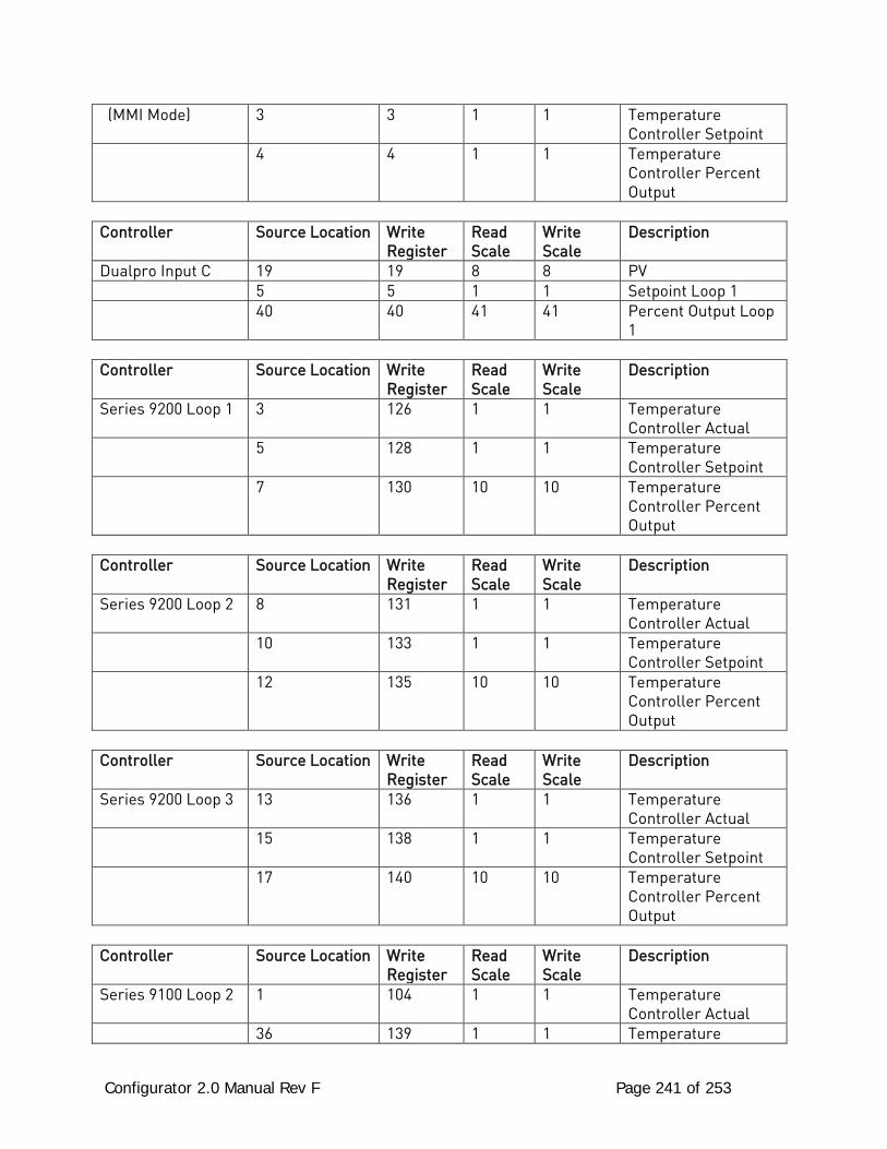
Configurator 2.0 Manual Rev F Page 241 of 253
(MMI Mode) 3 3 1 1 Temperature Controller Setpoint
4 4 1 1 Temperature Controller Percent Output
Controller Source Location Write
Register Read Scale
Write Scale
Description
Dualpro Input C 19 19 8 8 PV 5 5 1 1 Setpoint Loop 1 40 40 41 41 Percent Output Loop
1
Controller Source Location Write Register
Read Scale
Write Scale
Description
Series 9200 Loop 1 3 126 1 1 Temperature Controller Actual
5 128 1 1 Temperature Controller Setpoint
7 130 10 10 Temperature Controller Percent Output
Controller Source Location Write
Register Read Scale
Write Scale
Description
Series 9200 Loop 2 8 131 1 1 Temperature Controller Actual
10 133 1 1 Temperature Controller Setpoint
12 135 10 10 Temperature Controller Percent Output
Controller Source Location Write
Register Read Scale
Write Scale
Description
Series 9200 Loop 3 13 136 1 1 Temperature Controller Actual
15 138 1 1 Temperature Controller Setpoint
17 140 10 10 Temperature Controller Percent Output
Controller Source Location Write
Register Read Scale
Write Scale
Description
Series 9100 Loop 2 1 104 1 1 Temperature Controller Actual
36 139 1 1 Temperature
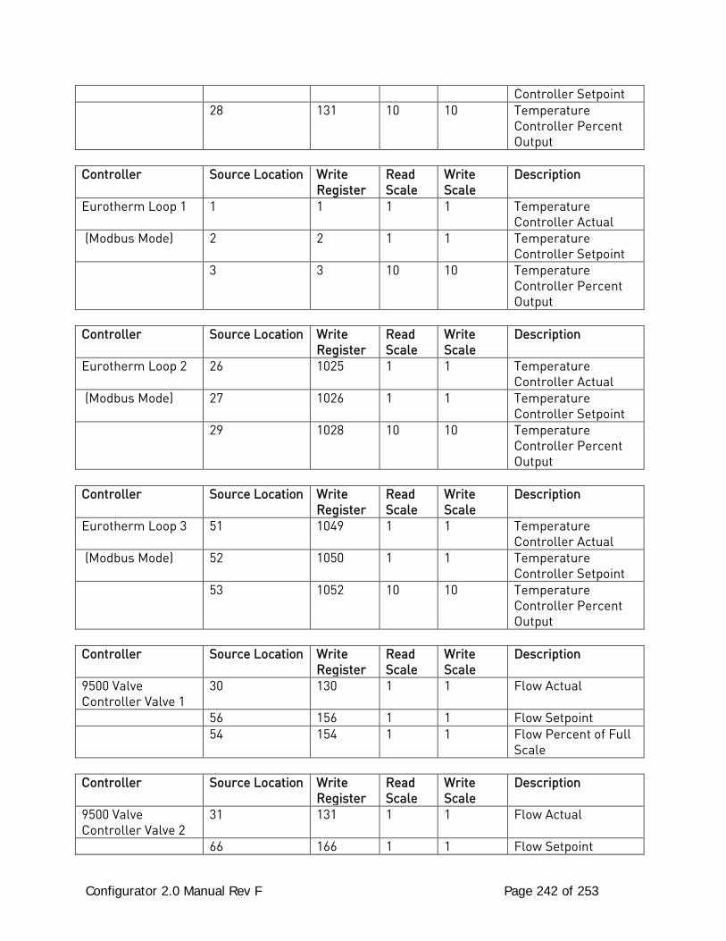
Configurator 2.0 Manual Rev F Page 242 of 253
Controller Setpoint 28 131 10 10 Temperature
Controller Percent Output
Controller Source Location Write
Register Read Scale
Write Scale
Description
Eurotherm Loop 1 1 1 1 1 Temperature Controller Actual
(Modbus Mode) 2 2 1 1 Temperature Controller Setpoint
3 3 10 10 Temperature Controller Percent Output
Controller Source Location Write
Register Read Scale
Write Scale
Description
Eurotherm Loop 2 26 1025 1 1 Temperature Controller Actual
(Modbus Mode) 27 1026 1 1 Temperature Controller Setpoint
29 1028 10 10 Temperature Controller Percent Output
Controller Source Location Write
Register Read Scale
Write Scale
Description
Eurotherm Loop 3 51 1049 1 1 Temperature Controller Actual
(Modbus Mode) 52 1050 1 1 Temperature Controller Setpoint
53 1052 10 10 Temperature Controller Percent Output
Controller Source Location Write
Register Read Scale
Write Scale
Description
9500 Valve Controller Valve 1
30 130 1 1 Flow Actual
56 156 1 1 Flow Setpoint 54 154 1 1 Flow Percent of Full
Scale
Controller Source Location Write Register
Read Scale
Write Scale
Description
9500 Valve Controller Valve 2
31 131 1 1 Flow Actual
66 166 1 1 Flow Setpoint
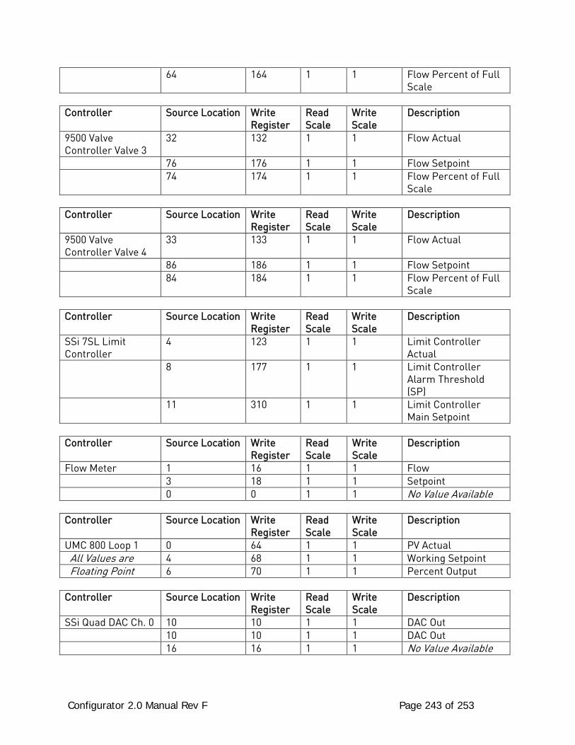
Configurator 2.0 Manual Rev F Page 243 of 253
64 164 1 1 Flow Percent of Full Scale
Controller Source Location Write
Register Read Scale
Write Scale
Description
9500 Valve Controller Valve 3
32 132 1 1 Flow Actual
76 176 1 1 Flow Setpoint 74 174 1 1 Flow Percent of Full
Scale
Controller Source Location Write Register
Read Scale
Write Scale
Description
9500 Valve Controller Valve 4
33 133 1 1 Flow Actual
86 186 1 1 Flow Setpoint 84 184 1 1 Flow Percent of Full
Scale
Controller Source Location Write Register
Read Scale
Write Scale
Description
SSi 7SL Limit Controller
4 123 1 1 Limit Controller Actual
8 177 1 1 Limit Controller Alarm Threshold (SP)
11 310 1 1 Limit Controller Main Setpoint
Controller Source Location Write
Register Read Scale
Write Scale
Description
Flow Meter 1 16 1 1 Flow 3 18 1 1 Setpoint 0 0 1 1 No Value Available
Controller Source Location Write Register
Read Scale
Write Scale
Description
UMC 800 Loop 1 0 64 1 1 PV Actual All Values are 4 68 1 1 Working Setpoint Floating Point 6 70 1 1 Percent Output
Controller Source Location Write Register
Read Scale
Write Scale
Description
SSi Quad DAC Ch. 0 10 10 1 1 DAC Out 10 10 1 1 DAC Out 16 16 1 1 No Value Available
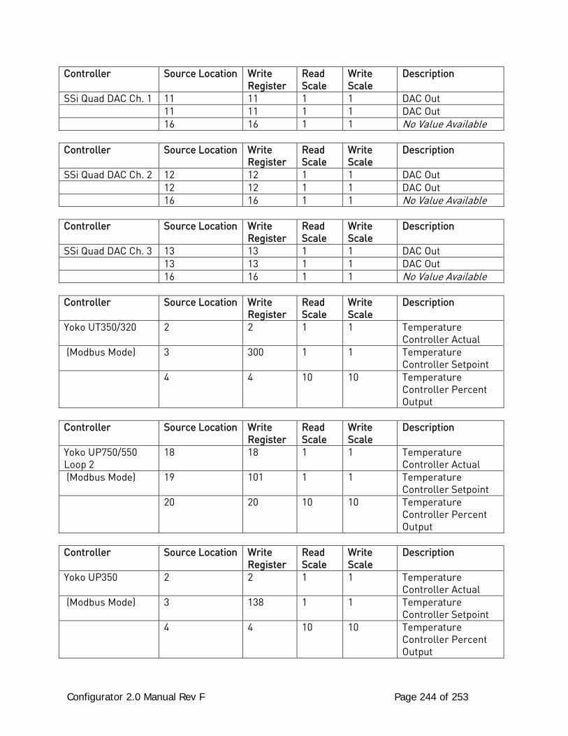
Configurator 2.0 Manual Rev F Page 244 of 253
Controller Source Location Write Register
Read Scale
Write Scale
Description
SSi Quad DAC Ch. 1 11 11 1 1 DAC Out 11 11 1 1 DAC Out 16 16 1 1 No Value Available
Controller Source Location Write Register
Read Scale
Write Scale
Description
SSi Quad DAC Ch. 2 12 12 1 1 DAC Out 12 12 1 1 DAC Out 16 16 1 1 No Value Available
Controller Source Location Write Register
Read Scale
Write Scale
Description
SSi Quad DAC Ch. 3 13 13 1 1 DAC Out 13 13 1 1 DAC Out 16 16 1 1 No Value Available
Controller Source Location Write Register
Read Scale
Write Scale
Description
Yoko UT350/320 2 2 1 1 Temperature Controller Actual
(Modbus Mode) 3 300 1 1 Temperature Controller Setpoint
4 4 10 10 Temperature Controller Percent Output
Controller Source Location Write
Register Read Scale
Write Scale
Description
Yoko UP750/550 Loop 2
18 18 1 1 Temperature Controller Actual
(Modbus Mode) 19 101 1 1 Temperature Controller Setpoint
20 20 10 10 Temperature Controller Percent Output
Controller Source Location Write
Register Read Scale
Write Scale
Description
Yoko UP350 2 2 1 1 Temperature Controller Actual
(Modbus Mode) 3 138 1 1 Temperature Controller Setpoint
4 4 10 10 Temperature Controller Percent Output
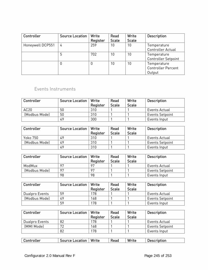
Configurator 2.0 Manual Rev F Page 245 of 253
Controller Source Location Write Register
Read Scale
Write Scale
Description
Honeywell DCP551 4 259 10 10 Temperature Controller Actual
5 702 10 10 Temperature Controller Setpoint
0 0 10 10 Temperature Controller Percent Output
Events Instruments
Controller Source Location Write Register
Read Scale
Write Scale
Description
AC20 50 310 1 1 Events Actual (Modbus Mode) 50 310 1 1 Events Setpoint 49 300 1 1 Events Input
Controller Source Location Write Register
Read Scale
Write Scale
Description
Yoko 750 49 310 1 1 Events Actual (Modbus Mode) 49 310 1 1 Events Setpoint 49 310 1 1 Events Input
Controller Source Location Write Register
Read Scale
Write Scale
Description
ModMux 97 97 1 1 Events Actual (Modbus Mode) 97 97 1 1 Events Setpoint 98 98 1 1 Events Input
Controller Source Location Write Register
Read Scale
Write Scale
Description
Dualpro Events 59 178 1 1 Events Actual (Modbus Mode) 49 168 1 1 Events Setpoint 59 178 1 1 Events Input
Controller Source Location Write Register
Read Scale
Write Scale
Description
Dualpro Events 82 178 1 1 Events Actual (MMI Mode) 72 168 1 1 Events Setpoint 82 178 1 1 Events Input
Controller Source Location Write Read Write Description
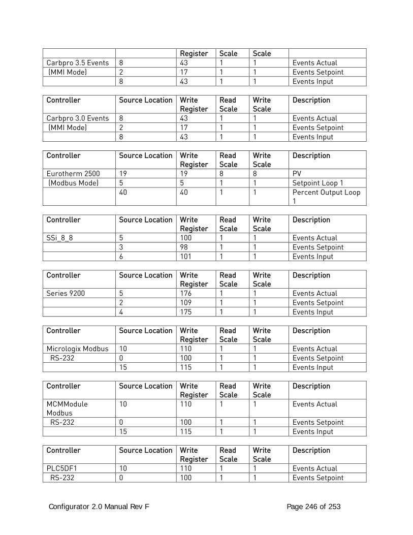
Configurator 2.0 Manual Rev F Page 246 of 253
Register Scale Scale Carbpro 3.5 Events 8 43 1 1 Events Actual (MMI Mode) 2 17 1 1 Events Setpoint 8 43 1 1 Events Input
Controller Source Location Write Register
Read Scale
Write Scale
Description
Carbpro 3.0 Events 8 43 1 1 Events Actual (MMI Mode) 2 17 1 1 Events Setpoint 8 43 1 1 Events Input
Controller Source Location Write Register
Read Scale
Write Scale
Description
Eurotherm 2500 19 19 8 8 PV (Modbus Mode) 5 5 1 1 Setpoint Loop 1 40 40 1 1 Percent Output Loop
1
Controller Source Location Write Register
Read Scale
Write Scale
Description
SSi_8_8 5 100 1 1 Events Actual 3 98 1 1 Events Setpoint 6 101 1 1 Events Input
Controller Source Location Write Register
Read Scale
Write Scale
Description
Series 9200 5 176 1 1 Events Actual 2 109 1 1 Events Setpoint 4 175 1 1 Events Input
Controller Source Location Write Register
Read Scale
Write Scale
Description
Micrologix Modbus 10 110 1 1 Events Actual RS-232 0 100 1 1 Events Setpoint 15 115 1 1 Events Input
Controller Source Location Write Register
Read Scale
Write Scale
Description
MCMModule Modbus
10 110 1 1 Events Actual
RS-232 0 100 1 1 Events Setpoint 15 115 1 1 Events Input
Controller Source Location Write Register
Read Scale
Write Scale
Description
PLC5DF1 10 110 1 1 Events Actual RS-232 0 100 1 1 Events Setpoint
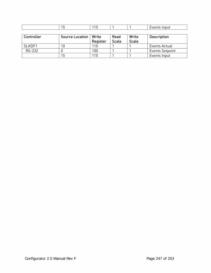
Configurator 2.0 Manual Rev F Page 247 of 253
15 115 1 1 Events Input
Controller Source Location Write Register
Read Scale
Write Scale
Description
SLKDF1 10 110 1 1 Events Actual RS-232 0 100 1 1 Events Setpoint 15 115 1 1 Events Input
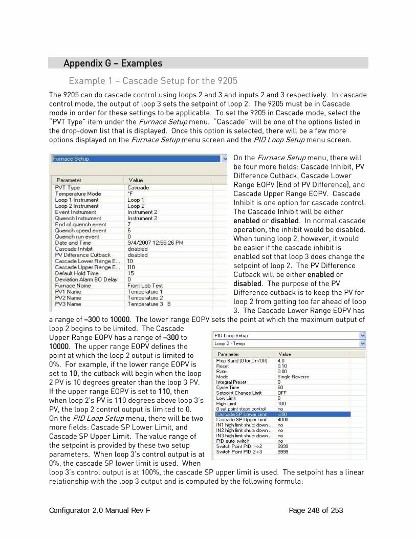
Configurator 2.0 Manual Rev F Page 248 of 253
Appendix G – Examples
Example 1 – Cascade Setup for the 9205 The 9205 can do cascade control using loops 2 and 3 and inputs 2 and 3 respectively. In cascade control mode, the output of loop 3 sets the setpoint of loop 2. The 9205 must be in Cascade mode in order for these settings to be applicable. To set the 9205 in Cascade mode, select the “PVT Type” item under the Furnace Setup menu. “Cascade” will be one of the options listed in the drop-down list that is displayed. Once this option is selected, there will be a few more options displayed on the Furnace Setup menu screen and the PID Loop Setup menu screen.
On the Furnace Setup menu, there will be four more fields: Cascade Inhibit, PV Difference Cutback, Cascade Lower Range EOPV (End of PV Difference), and Cascade Upper Range EOPV. Cascade Inhibit is one option for cascade control. The Cascade Inhibit will be either enabled or disabled. In normal cascade operation, the inhibit would be disabled. When tuning loop 2, however, it would be easier if the cascade inhibit is enabled sot that loop 3 does change the setpoint of loop 2. The PV Difference Cutback will be either enabled or disabled. The purpose of the PV Difference cutback is to keep the PV for loop 2 from getting too far ahead of loop 3. The Cascade Lower Range EOPV has
a range of –300 to 10000. The lower range EOPV sets the point at which the maximum output of loop 2 begins to be limited. The Cascade Upper Range EOPV has a range of –300 to 10000. The upper range EOPV defines the point at which the loop 2 output is limited to 0%. For example, if the lower range EOPV is set to 10, the cutback will begin when the loop 2 PV is 10 degrees greater than the loop 3 PV. If the upper range EOPV is set to 110, then when loop 2’s PV is 110 degrees above loop 3’s PV, the loop 2 control output is limited to 0. On the PID Loop Setup menu, there will be two more fields: Cascade SP Lower Limit, and Cascade SP Upper Limit. The value range of the setpoint is provided by these two setup parameters. When loop 3’s control output is at 0%, the cascade SP lower limit is used. When loop 3’s control output is at 100%, the cascade SP upper limit is used. The setpoint has a linear relationship with the loop 3 output and is computed by the following formula:

Configurator 2.0 Manual Rev F Page 249 of 253
Loop 2 Setpoint = (Loop 3 Output / 100%) * (SP upper limit – SP lower limit) + SP lower limit The Cascade SP Lower Limit has a range of –300 to 4000. The Cascade SP Upper Limit has a range of –300 to 4000.
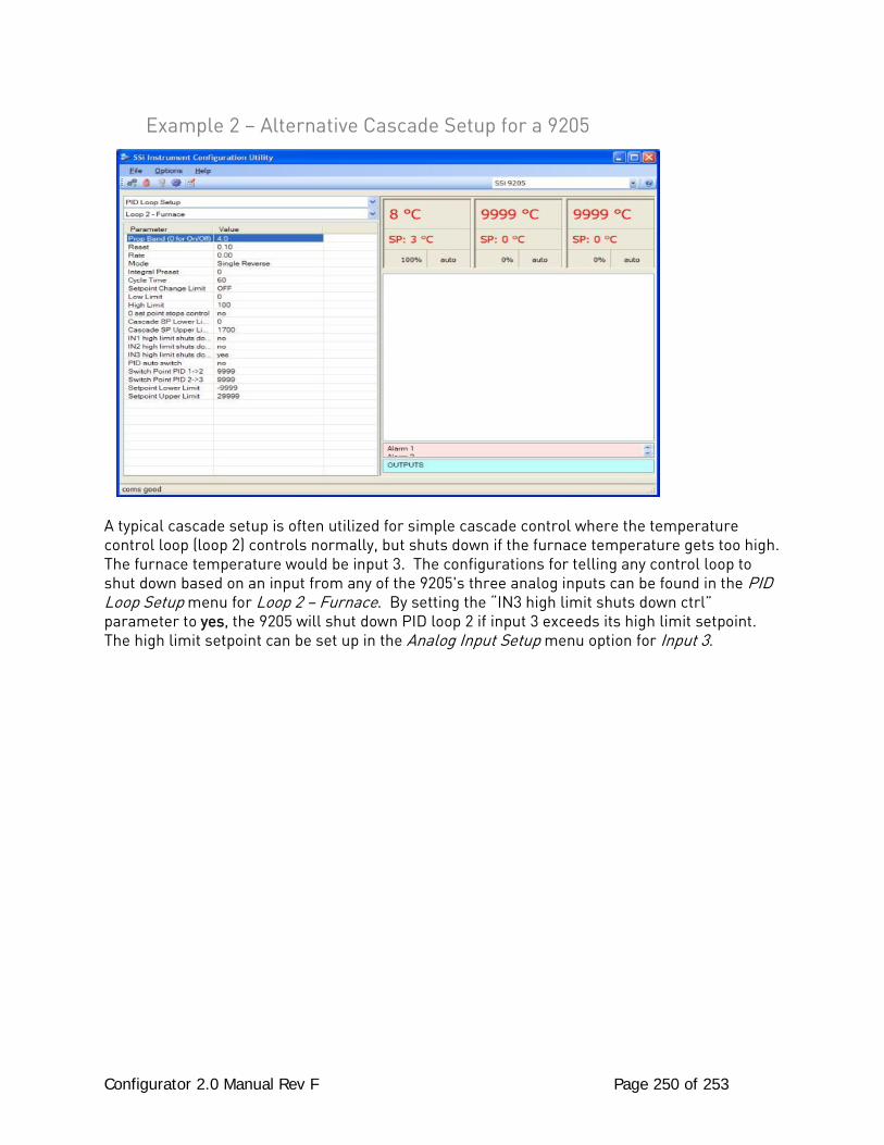
Configurator 2.0 Manual Rev F Page 250 of 253
Example 2 – Alternative Cascade Setup for a 9205
A typical cascade setup is often utilized for simple cascade control where the temperature control loop (loop 2) controls normally, but shuts down if the furnace temperature gets too high. The furnace temperature would be input 3. The configurations for telling any control loop to shut down based on an input from any of the 9205's three analog inputs can be found in the PID Loop Setup menu for Loop 2 – Furnace. By setting the “IN3 high limit shuts down ctrl” parameter to yes, the 9205 will shut down PID loop 2 if input 3 exceeds its high limit setpoint. The high limit setpoint can be set up in the Analog Input Setup menu option for Input 3.
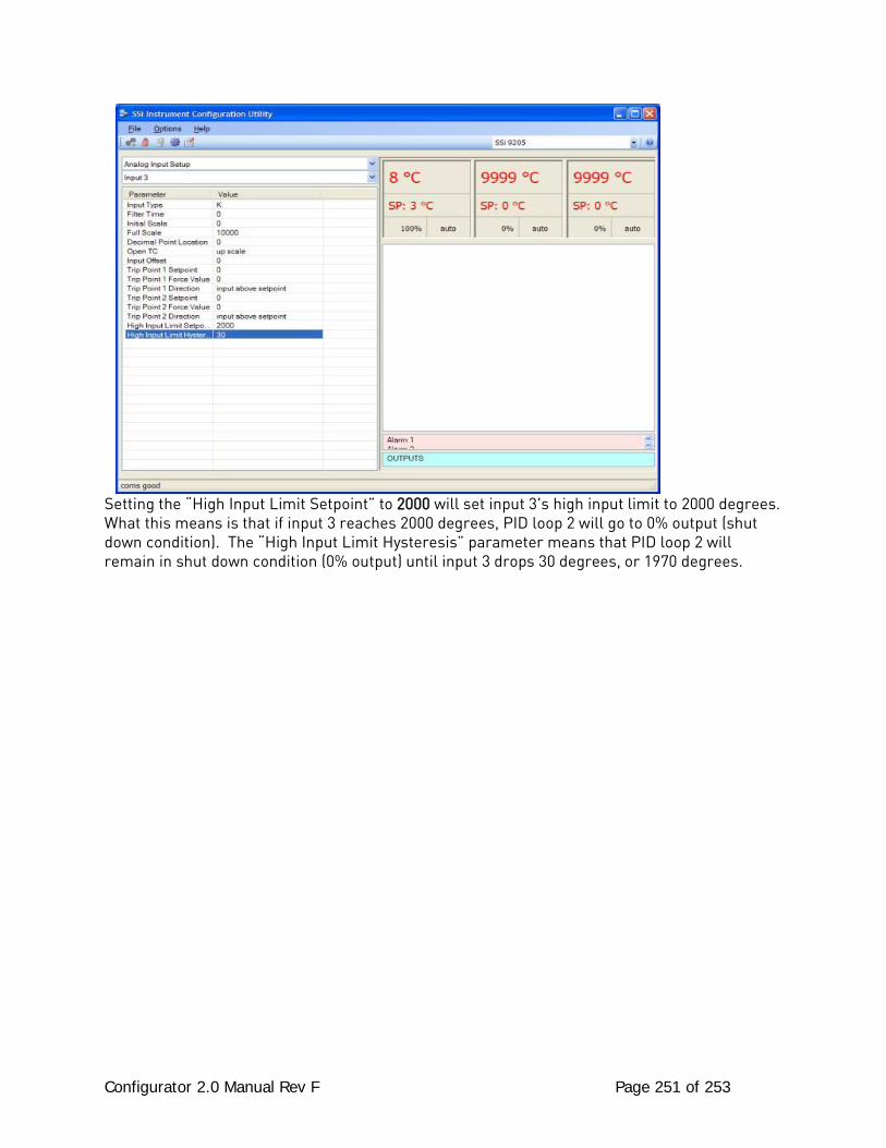
Configurator 2.0 Manual Rev F Page 251 of 253
Setting the “High Input Limit Setpoint” to 2000 will set input 3's high input limit to 2000 degrees. What this means is that if input 3 reaches 2000 degrees, PID loop 2 will go to 0% output (shut down condition). The “High Input Limit Hysteresis” parameter means that PID loop 2 will remain in shut down condition (0% output) until input 3 drops 30 degrees, or 1970 degrees.

Configurator 2.0 Manual Rev F Page 252 of 253
Revision History
Revision Level Date Description MCO #
- 5/26/06 Initial Release N/A A 1/24/07 Updated to Reflect Configurator 2.0 2042 B 3/28/07 Added menus for 9220, 9005, 9120,
Appendices A, B N/A
C 10/23/07 Added Tuning Assistant to 9200, 9220 menu; Added 8500 option (VR); Added 9205 Menu options; Added 9210 Menu options; Added 9215 Menu options; Added “Flash Card Management” appendix; Updated title page to reflect new logo; Added “Slave Instrument Mapping” appendix; Added “Examples” appendix (Example 1); Updated “Revision History” section; Updated menu headings for tool bar buttons; Added “SDRecorder Installation” appendix
2051
D 6/6/08 Added note to “Recipe Description” text on page 24
2061
E 03/06/09 Updated the 9120 section; Updated Appendix D; Updated PID Loop Setup menu option; Updated Alarm Setup menu option; Added warning to Analog Input Setup menu (9200/9220); Updated Analog Output Setup menu (9200/9220); Added 9021 Instrumentation (DAQ); Added Aux Instruments, Communication Setup, Device Configuration, Input Offsets, and Aux Instrument Setup menu options to 8500; Removed DAQ references in the 8500 section, Removed captions from the 8500 section, Updated the Range Setups menu option in the 8500 section; Updated RAMPR opcode; Added GDELAY, GHDELAY, GLDELAY to opcode list; Updated Relay Assignments menu (9200/9220); Updated PID Loop Setup menu (9200/9220); Updated Alarm Setup menu (9200/9220); Updated System Management screen shots and functionality; Added COF description; Added note to Furnace Setup menu (9005/9120/9200/9215/9220); Updated the Tuning Assistant section (9200); Added the Analog Inputs section; Added BO_start, RMPRAUX opcodes; Added DF1 Configuration
2053
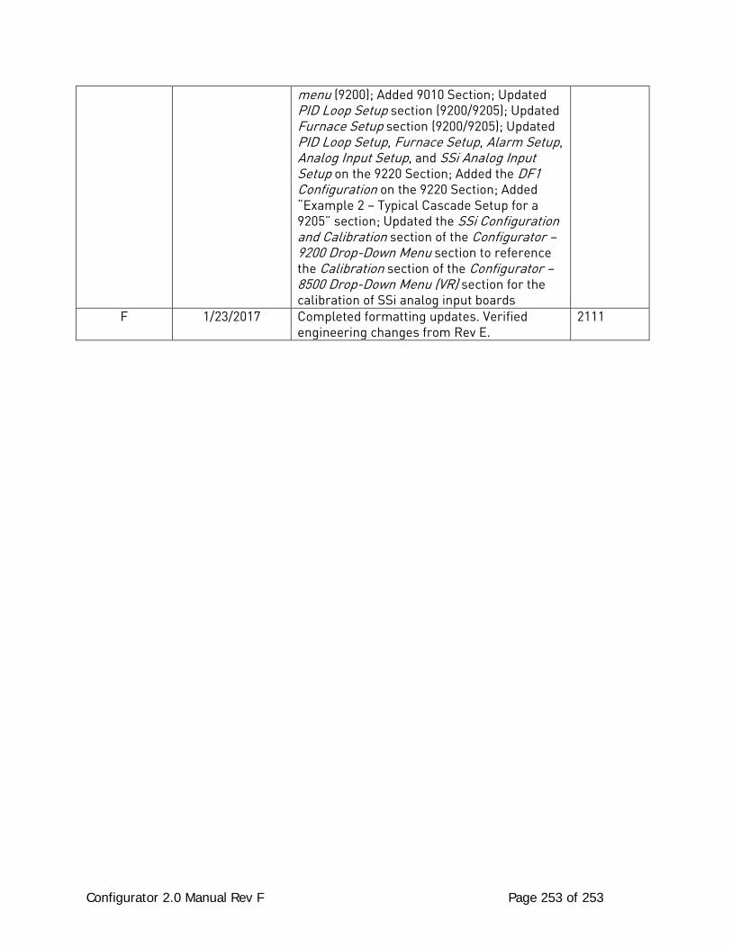
Configurator 2.0 Manual Rev F Page 253 of 253
menu (9200); Added 9010 Section; Updated PID Loop Setup section (9200/9205); Updated Furnace Setup section (9200/9205); Updated PID Loop Setup, Furnace Setup, Alarm Setup, Analog Input Setup, and SSi Analog Input Setup on the 9220 Section; Added the DF1 Configuration on the 9220 Section; Added “Example 2 – Typical Cascade Setup for a 9205” section; Updated the SSi Configuration and Calibration section of the Configurator – 9200 Drop-Down Menu section to reference the Calibration section of the Configurator – 8500 Drop-Down Menu (VR) section for the calibration of SSi analog input boards
F 1/23/2017 Completed formatting updates. Verified engineering changes from Rev E.
2111