Configuration Manual for Catalog LV 10 • 2015 Chapter 8 · iec/en 60669-1, (vde 0632-1) ...
62
Totally Integrated Power – SENTRON Switching Devices siemens.com/lowvoltage Configu- ration Manual Edition 10/2014 © Siemens AG 2015
Transcript of Configuration Manual for Catalog LV 10 • 2015 Chapter 8 · iec/en 60669-1, (vde 0632-1) ...

Totally Integrated Power – SENTRON
Switching Devices
siemens.com/lowvoltage
Configu-ration Manual
Edition10/2014
PH_08_10-2014_umschlag_en.indd 3PH_08_10-2014_umschlag_en.indd 3 02.02.2015 12:13:4702.02.2015 12:13:47
© Siemens AG 2015

© Siemens AG 2015

Siemens · 10/2014
For further technical product information:
Service & Support Portal:www.siemens.com/lowvoltage/product-support .
Product List: Technical specifications
Entry List: Certificates / Characteristics /Download / FAQ / Manuals /Updates
2 Introduction
5 5TE8 control switches
7 5TE48 pushbuttons
9 5TE58 light indicators
10 5TE81/82 ON/OFF switches
11 5TE83...88 ON/OFF switches
13 5TL1 ON/OFF switches
15 5TE DC isolators
17 5ST busbars for modular installation devices
18 5TT4 remote control switches
24 5TT4 switching relays
5TT5 Insta contactors26 5TT50 Insta contactors,
AC/DC technology32 5TT58 Insta contactors,
AC technology
38 5TT3 soft-starting devices
40 Controls
7LF, 5TT3 timers41 7LF4 digital time switches47 7LF5 mechanical time switches51 7LF6 timers for buildings56 5TT3 timers for industry
Switching Devices
PH_08.book Seite 1 Dienstag, 27. Januar 2015 11:39 11
© Siemens AG 2015
2 Siemens · 10/2014
Introduction
Switching Devices
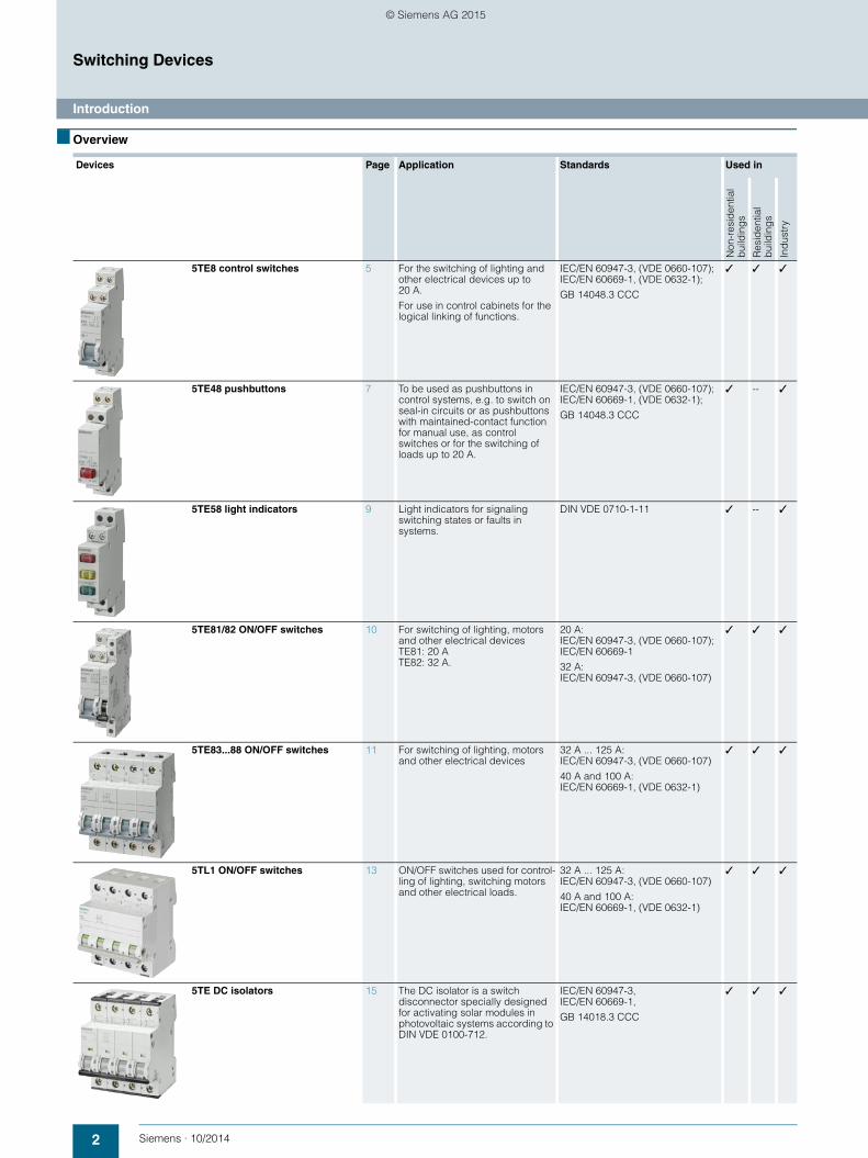
■ Overview
Devices Page Application Standards Used in
Non
-res
iden
tial
bui
ldin
gs
Res
iden
tial
bui
ldin
gs
Ind
ustr
y
5TE8 control switches 5 For the switching of lighting and other electrical devices up to 20 A.
For use in control cabinets for the logical linking of functions.
IEC/EN 60947-3, (VDE 0660-107);IEC/EN 60669-1, (VDE 0632-1);
GB 14048.3 CCC
✓ ✓ ✓
5TE48 pushbuttons 7 To be used as pushbuttons in control systems, e.g. to switch on seal-in circuits or as pushbuttons with maintained-contact function for manual use, as control switches or for the switching of loads up to 20 A.
IEC/EN 60947-3, (VDE 0660-107);IEC/EN 60669-1, (VDE 0632-1);
GB 14048.3 CCC
✓ -- ✓
5TE58 light indicators 9 Light indicators for signaling switching states or faults in systems.
DIN VDE 0710-1-11 ✓ -- ✓
5TE81/82 ON/OFF switches 10 For switching of lighting, motors and other electrical devices TE81: 20 ATE82: 32 A.
20 A:IEC/EN 60947-3, (VDE 0660-107);IEC/EN 60669-1
32 A:IEC/EN 60947-3, (VDE 0660-107)
✓ ✓ ✓
5TE83...88 ON/OFF switches 11 For switching of lighting, motors and other electrical devices
32 A ... 125 A:IEC/EN 60947-3, (VDE 0660-107)
40 A and 100 A:IEC/EN 60669-1, (VDE 0632-1)
✓ ✓ ✓
5TL1 ON/OFF switches 13 ON/OFF switches used for control-ling of lighting, switching motors and other electrical loads.
32 A ... 125 A:IEC/EN 60947-3, (VDE 0660-107)
40 A and 100 A:IEC/EN 60669-1, (VDE 0632-1)
✓ ✓ ✓
5TE DC isolators 15 The DC isolator is a switch disconnector specially designed for activating solar modules in photovoltaic systems according to DIN VDE 0100-712.
IEC/EN 60947-3,IEC/EN 60669-1,
GB 14018.3 CCC
✓ ✓ ✓
PH_08.book Seite 2 Dienstag, 27. Januar 2015 11:39 11
© Siemens AG 2015

3Siemens · 10/2014
Switching Devices
Introduction
Devices Page Application Standards Used in
Non
-res
iden
-tia
l bui
ldin
gs
Res
iden
tial
bui
ldin
gs
Ind
ustr
y
5ST busbars formodular installation devices
17 For fast and safe connection IEC/EN 60439-1, (VDE 0660-500) ✓ -- ✓
5TT4 remote control switches 18 For the switching of lightingup to 16 A in rooms using several pushbuttons and central ON/OFF switches.
IEC 60669-1;IEC 60669-2-2;
DIN EN 60669-1-1 (VDE 0632);DIN EN 60669-2-2 (VDE 0632-2-2)
✓ ✓ ✓
5TT4 switching relays 24 For the switching of small loadsup to 16 A or as coupling devices in control systems.
DIN EN 60947-5-1, (VDE 0660-200)DIN EN 60947-1, (VDE 0660-100);
GB 14048.4 CCC
✓ -- ✓
5TT5 Insta contactors5TT50 Insta contactors, AC/DC technology
26 Insta contactors 20 A, 25 A, 40 A and 63 A for the switching of heating and lighting, such asfluorescent lamps, incandescent lamps, ohmic or inductive loads.
IEC 60947-4-1;IEC 60947-5-1;IEC 61095;
EN 60947-4-1;EN 60947-5-1;EN 61095;
VDE 0660;
UL 508;
GB 14048.4 CCC
✓ ✓ ✓
5TT58 Insta contactors, AC technology
32 Insta contactors 20 A, 25 A, 40 A and 63 A for the switching of heating and lighting, such asfluorescent lamps, incandescent lamps, ohmic or inductive loads.
IEC 60947-4-1;IEC 60947-5-1;IEC 61095;
EN 60947-4-1;EN 60947-5-1;EN 61095;
VDE 0660;
NF C 61-480, (NF EN 61095)
✓ ✓ ✓
5TT3 soft-starting devices 38 Protection of machines withtransmission, belt or chain drives, conveyor belts, fans, pumps, compressors, packing machines or door operating mechanisms
DIN EN 60947-4-2,(VDE 0660-117)
-- -- ✓
Controls 40 For the ON/OFF switching of loads, contact selection for light-ing installations, OFF switching of direct currents and the switching of safety extra-low voltages.
A wide range of options for practical use.
duration
1I201_07254a t
6 ...10p
PH_08.book Seite 3 Dienstag, 27. Januar 2015 11:39 11
© Siemens AG 2015

4 Siemens · 10/2014
Introduction
Switching Devices
Devices Page Application Standards Used in
Non
-res
iden
tial
bui
ldin
gs
Res
iden
tial
bui
ldin
gs
Ind
ustr
y
7LF, 5TT3 timers7LF4 digital time switches 41 Minute-precise switching of devices and
system components in day, week and year programs. Unique due to the wide variety of functions offered by the Mini and Top versions; for PC programming Astro, Profi and Expert
IEC 60730-1 and IEC 60730-2-7
EN 60730-1 and EN 60730-2-7
VDE 0631-1 and -2-7
✓ ✓ ✓
7LF5 mechanical time switches
47 Accurate and 15-minute switching accuracy. With automatic time setting during commissioning and automatic switching to daylight savings.
IEC 60730-1 and IEC 60730-2-7
EN 60730-1 and EN 60730-2-7
VDE 0631-1 and -2-7
UL 60730UL 917
✓ ✓ ✓
7LF6 timers for buildings 51 Lighting controls with stairwell lighting timers ensure the safe use of stairwells and save energy. Expanded applications for common rooms and garages, as well as the timeswitching of ventilators and fluorescent lamps.
IEC 60699
EN 60669, DIN 18015
✓ ✓
5TT3 timers for industry 56 Multifunctional, delay, wiper, flashing andOFF-delay timers in control circuits expand the use of distribution boards in both small and large plants.
IEC 60255
EN 60255
✓
PH_08.book Seite 4 Dienstag, 27. Januar 2015 11:39 11
© Siemens AG 2015
5Siemens · 10/2014
Switching Devices
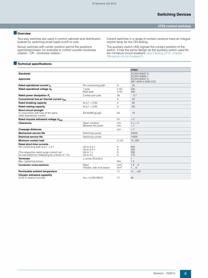
5TE8 control switches
■ Overview
Two-way switches are used in control cabinets and distribution boards for switching small loads on/off or over.
Group switches with center position permit the positions open/stop/closed, for example to control counter-clockwise rotation - Off - clockwise rotation.
Control switches in a range of contact versions have an integral control lamp for the ON setting.
The auxiliary switch (AS) signals the contact position of the switch. It has the same design as the auxiliary switch used for the miniature circuit breakers (see Catalog LV10, chapter "Miniature circuit breakers").
■ Technical specifications
5TE81
Standards IEC/EN 60947-3; IEC/EN 60669-1
Approvals IEC/EN 60947-3;GB 14048.3-2008 CCC
Rated operational current Ie Per conducting path A 20
Rated operational voltage Ue 1-pole V AC 230Multi-pole V AC 400
Rated power dissipation Pv Contact per pole VA 0.7
Conventional free-air thermal current Ithe A 20
Rated breaking capacity At p.f. = 0.65 A 60
Rated making capacity At p.f. = 0.65 A 60
Short-circuit strengthIn conjunction with fuse of the same rated operational current
EN 60269 gL/gG kA 10
Rated impulse withstand voltage Uimp kV > 5
Clearances Open contacts mm 2 × > 2Between the poles mm > 7
Creepage distances mm > 7
Mechanical service life Switching cycles 25000
Electrical service life Switching cycles 10000
Minimum contact load V; mA 10; 300
Rated short-time currents Per conducting path at p.f. = 0.7 Up to 0.2 s A 650
Up to 0.5 s A 400(The respective rated surge current can Up to 1 s A 290be calculated by multiplying by a factor of 1.5). Up to 3 s A 170
Terminals ± screw (Pozidriv) 1Max. tightening torque Nm 1.2
Conductor cross-sections Rigid mm2 1.5 ... 6Flexible, with end sleeve mm2 1 ... 6
Permissible ambient temperature °C -5 ... +40
Climatic withstand capabilityAt 95 % relative humidity Acc. to DIN 50015 °C 45
PH_08.book Seite 5 Dienstag, 27. Januar 2015 11:39 11
© Siemens AG 2015

6 Siemens · 10/2014
5TE8 control switches
Switching Devices
■ Dimensional drawings
■ Circuit diagrams
Graphic symbols
Two-way and group switches with center position, 20 A 5TE8 control switches, 20 A, with lamp
5TE8151 5TE8152 5TE8141 5TE81425TE8153 5TE8161 5TE8162
5TE8101 5TE8102 5TE8103 5TE8101-3 5TE8105
5TE8 control switches, 20 A, with lamp and auxiliary switch
5ST3 auxiliary switches
5TE8108 5ST3010 5ST3011 5ST3012
Two-way switches, group switches with center position, 20 A 5TE8 control switches, 20 A, with lamp
5TE8151 5TE8152 5TE8153 5TE81015TE8101-3
5TE8105 5TE8102 5TE8103
5TE8 control switches, 20 A,with lamp and auxiliary switch
5TE8141 5TE8161 5TE8108
5ST3 auxiliary switches
5TE8142 5TE8162 5TE3010 5ST3011 5ST3012
1
2
L1
7 2444
64
I201
_078
88a
45 67 90
18 18 18
70
2 2 4
1 1 3
71
2
18
3
4
3 5
8
4 6 L1 L2
1
2 2
4
2
1 1
7 2444
64
I201
_080
08a
45 67 90
18 18 18
70
3 3 5
N
4 6
N N
7 2444
64
45 67 90
70
2
4
1
27
3
7/N 13
5 21
8/N 14
6 22 I201
_115
83a
9 6 4470
I201
_063
35
9045
2
1
4
3
2
1
4
3
6
5
8
7
2
1
4
3
6
5
8
7
2
1 N N 1
2
2
1
4
3 N
2
1
4
3
6
5 N
1
L1
2 � �
��
1
2
3
4
5
6
N 13
14 22
21
1
L1
2 3
L2
4 1
L1
2 3
L2
4
2214
1321
2414
1323
2212
1121
PH_08.book Seite 6 Dienstag, 27. Januar 2015 11:39 11
© Siemens AG 2015

7Siemens · 10/2014
Switching Devices
5TE48 pushbuttons
■ Overview
The pushbuttons are used in control systems, e.g. to switch on seal-in circuits or as pushbuttons with maintained-contact
function for manual use, as control switches or for the switching of loads up to 20 A.
■ Technical specifications
5TE48
Standards IEC/EN 60947-3 IEC/EN 60669-1
Approvals IEC/EN 60947-3 (VDE 0660-107)
Rated operational current Ie Per conducting path A 20
Rated operational voltage Ue 1-pole V AC 230Multi-pole V AC 400
Rated power dissipation Pv Per pole VA 0.6
Conventional free-air thermal current Ithe A 20
Rated breaking capacity At p.f. = 0.65 A 60
Rated making capacity At p.f. = 0.65 A 60
Rated impulse withstand voltage Uimp kV > 5
Clearances Open contacts mm 2 × > 2Between the poles mm > 7
Creepage distances mm > 7
Mechanical service life Switching cycles 25000
Minimum contact load V; mA 10; 300
Rated short-time currentsPer conducting path at p.f. = 0.7 Up to 0.2 s A 650
Up to 0.5 s A 400(The respective rated surge current can Up to 1 s A 290be calculated by multiplying by a factor of 1.5). Up to 3 s A 170
Terminals ± screw (Pozidriv) 1Max. tightening torque Nm 1.2
Conductor cross-sections Rigid mm2 1.5 ... 6Flexible, with end sleeve mm2 1 ... 6
Permissible ambient temperature °C -5 ... +40
Climatic withstand capabilityAt 95 % relative humidity Acc. to DIN 50015 °C 45
Power loss of 5TG805. lamps 5TG8050 5TG8051 5TG8052 5TG8053 5TG8054 5TG8055
Rated operational voltage Ue V AC 12 24 48 60 115 230
Rated power dissipation Pv mW 70 160 350 420 70 170
Rated operational voltage Ue V DC 12 24 48 60 110 220
Rated power dissipation Pv mW 85 190 450 550 50 135
Power loss of 5TG805.-. LEDs 5TG805.-.
Rated power dissipation Pv• LED VA 0.4
Color coding according to IEC 60073
Color Safety of people or environment
Process state System state
Red Danger Emergency Faulty
Yellow Warning/Caution Abnormal
Green Safety Normal
Blue Stipulation
White, gray, black No special significance assigned
PH_08.book Seite 7 Dienstag, 27. Januar 2015 11:39 11
© Siemens AG 2015

8 Siemens · 10/2014
5TE48 pushbuttons
Switching Devices
■ Dimensional drawings
■ Circuit diagrams
Graphic symbols
5TE48 pushbuttons
5TE4820 5TE4821 5TE4800 5TE4812 5TE4813 5TE4814 5TE4823 5TE4822 5TE4805 5TE4824 5TE4806
5TE4807 5TE4808 5TE4810 5TE4811
5TE4804 pushbuttons 5TE48 double pushbuttons with maintained-contact function
5TE4804 5TE4830 5TE4831 5TE4840 5TE4841
5TE4800 5TE4805 5TE4806 5TE4807 5TE4808
5TE4804 5TE4810 5TE4823 5TE4824 5TE4822
5TE4811 5TE4812 5TE4813 55TE4830 5TE4831
5TE4814 5TE4820 5TE4821 5TE4840 5TE4841
7 2444
64
I201
_078
75b
45 67 90
70
18
2
L1 L2
18
2
3
4
8
18
2
3
4
8/N
18
2
3
4
18
X6
1
2
N
18
X6
1
2
N
3
4
1
5
1 7/N
6
5
1 7
6
4
1 3
7 2444
64
I201
_119
84a
45 67 90
70
18
1
2 4
3
X5 N
X6 N
7 2444
64I2
01_0
7870
b
45 67 90
70
18
1
2 4
18
6
1
2
8
18
1
2
3
4
3
5 7
4
3
X5 N
X6 N
2
1
4
3 1
2
3
4 X6
X5
N
N
2
1
4
3
2
1
4
3
NX6 2
1
4
3
NX62
1
NX6
2
1
4
3
2
1
4
3
6
5
8/N
7/N
2
1
4
3
6
5
8
7
2 4
1 3
2 4
1 3
6 8
5 7
1
L1
2 3
L2
4
2
1
4
3
NX6 2
1
NX6 2
1
4
3
N
N
X6
X5
2
1
4
3
N
N
X6
X5
PH_08.book Seite 8 Dienstag, 27. Januar 2015 11:39 11
© Siemens AG 2015

9Siemens · 10/2014
Switching Devices
5TE58 light indicators
■ Overview
Light indicators are used to signal switching states or faults in systems.
They are available as single, double or triple light indicators.
■ Technical specifications
Color coding according to IEC 60073
■ Dimensional drawings
■ Circuit diagrams
Graphic symbols
5TE58
Standards DIN VDE 0710-1-11
Rated operational voltage Ue Max. V AC 230 (for different voltages see 5TG8 lamps)
Rated power dissipation Pv VA See 5TG8 lamps
Clearances Between the terminals mm > 7
Terminals ± screw (Pozidriv) 1Max. tightening torque Nm 1.2
Conductor cross-sections Rigid mm2 1.5 ... 6Flexible, with end sleeve mm2 1 ... 6
Permissible ambient temperature °C -5 ... +40
Climatic withstand capabilityAt 95 % relative humidity Acc. to DIN 50015 °C 45
5TG805.
Rated power dissipation Pv• LED VA 0.4
Meaning
Color
Safety of people andenvironment
Process state System state
Red Danger Emergency Faulty
Yellow Warning/Caution Abnormal
Green Safety Normal
Blue Stipulation
White No special significance assigned
5TE5800 5TE5804
5TE5801 5TE5802 5TE5803
7 2444
64
I201
_078
95a
45 67 90
68
X2 X2
18 18 18
NN N
X1
X2
X1X1
5TE5800 5TE5801 5TE58025TE5803
5TE5804
N
X1
N
X1
X3
X1
X3X2
N N
X1
PH_08.book Seite 9 Dienstag, 27. Januar 2015 11:39 11
© Siemens AG 2015

10 Siemens · 10/2014
5TE81/82 ON/OFF switches
Switching Devices
■ Overview
The devices are used for the switching of lighting, motors and other electrical devices.
There is a compact series of space-saving devices with up to 4 NO contacts in a single MW available for rated currents 20 A and 32 A.
In addition, the 5TE2 device versions can be used as switch dis-connectors according to EN 60947-1 and serve as main control switches for the disconnection or isolation of plants according to EN 60204-1.
■ Technical specifications
5TE81 5TE82
Standards IEC/EN 60947-3, (VDE 0660-107); IEC/EN 60669-1
IEC/EN 60947-3, (VDE 0660-107)
Approvals IEC/EN 60947-3 (VDE 0660-107)
Rated operational current Ie Per conducting path A 20 32
Rated operational voltage Ue 1-pole V AC 230400Multi-pole V AC
Rated power dissipation Pv Per pole, max. VA 0.7
Rated thermal current Ith A 20 32
Rated breaking capacity At p.f. = 0.65 A 60 96
Rated making capacity At p.f. = 0.65 A 60 96
Rated short-circuit making capacity IcmIn conjunction with fuse of the same rated operational current
DIN EN 60269 gL/gG kA 10
Rated impulse withstand voltage Uimp kV > 5
Clearances Open contacts mm 2 × > 2Between the poles mm > 7
Creepage distances mm > 7
Mechanical service life Switching cycles
25000
Electrical service life Switching cycles
10000
Minimum contact load V; mA 10; 300
Rated short-time withstand current Icw Per conducting path at p.f. = 0.7 Up to 0.2 s A 650 1000
Up to 0.5 s A 400 630(The corresponding rated surge current can be established by multiplying by factor 1.5.)
Up to 1 s A 290 450Up to 3 s A 170 250
Terminals ± screw (Pozidriv) 1Max. tightening torque Nm 1.2
Conductor cross-sections Rigid mm2 1.5 ... 6Flexible, with end sleeve mm2 1 ... 6
Permissible ambient temperature °C -5 ... +40
Climatic withstand capabilityAt 95 % relative humidity Acc. to DIN 50015 °C 45
PH_08.book Seite 10 Dienstag, 27. Januar 2015 11:39 11
© Siemens AG 2015

11Siemens · 10/2014
Switching Devices
5TE83...88 ON/OFF switches
5TE83 5TE84 5TE85 5TE86 5TE87 5TE88
Standards IEC/EN 60947-3 (VDE 0660-107)
-- IEC/EN 60669-1 (VDE 0632-1) --
Approvals EN 60669-1
Rated operational current Ie Per conducting path A 32 40 63 80 100 125
Rated operational voltage Ue 1-pole V AC 230Multi-pole V AC 400
Rated power dissipation Pv Per pole, max. VA 0.7 0.9 2.2 3.5 5.5 8.6
Rated thermal current Ith A 32 40 63 80 100 125
Rated breaking capacity At p.f. = 0.65 A 96 120 196 240 300 375
Rated making capacity At p.f. = 0.65 A 96 120 196 240 300 375
Rated short-circuit making capacity IcmIn conjunction with fuse of the same rated operational current
EN 60269 gL/gG kA 10
Rated impulse withstand voltage Uimp kV > 5
Clearances Open contacts mm > 7Between the poles mm > 7
Creepage distances mm > 7
Mechanical service life Switching cycles
20000
Electrical service life Switching cycles
10000 5000 1000
Minimum contact load V; mA 24; 300
Rated power 1-pole kW 5 6.5 10 13 16 16Switching of resistive loads 2-pole kW 9 11 18 22 28 28including moderate overload AC-21 3-/4-pole kW 15 15 30 39 48 48
Rated short-time withstand current IcwPer conducting path at p.f. = 0.7 Up to 0.2 s A 760 950 1500 2700 3400 3400
Up to 0.5 s A 500 630 1000 1650 2100 2100(The corresponding rated surge current can be established by multiplying by factor 1.5.)
Up to 1 s A 400 500 800 1350 1700 1700Up to 3 s A 280 350 560 800 1000 1000
Terminals ± screw (Pozidriv) 2 Max. tightening torque Nm 3.5
Conductor cross-sections Rigid mm2 1 ... 35 2.5 ... 50Flexible, with end sleeve mm2 1 ... 35 2.5 ... 50
Permissible ambient temperature °C -5 ... +40
Climatic withstand capabilityAt 95 % relative humidity Acc. to DIN 50015 °C 45
PH_08.book Seite 11 Dienstag, 27. Januar 2015 11:39 11
© Siemens AG 2015

12 Siemens · 10/2014
5TE83...88 ON/OFF switches
Switching Devices
■ Circuit diagrams
Graphic symbols
5TE8 ON/OFF switches
5ST3 auxiliary switches
5TE8 ON/OFF switches, 32 A to 125 A
5TE8311 5TE8312 5TE8313 5TE8314 5TE8315 5TE8411 5TE8412 5TE8413 5TE8414 5TE8415 5TE8511 5TE8512 5TE8513 5TE8514 5TE8515 5TE8521 5TE8522 5TE8523 5TE8524
5TE8533 5TE8611 5TE8612 5TE8613 5TE8614 5TE8615 5TE8711 5TE8712 5TE8713 5TE8714 5TE8715 5TE8721 5TE8722 5TE8723 5TE8724 5TE8811 5TE8812 5TE8813 5TE8814 5TE8815
3618 54 72
1 1 3 1 3 5 1 3 5 7/N
2 2 4 2 4 6 2 4 6 8/N
4464
6
45 90
I201
_125
63a
72
1 3 5 7
2 4 6 8
70
5ST3 auxiliary switches Phase connectors/N conductor connectors
5ST3010 5ST3011 5ST3012
5TE9112 5TE9113
9 6 4470
I201
_063
35
9045
18
70
I201
_115
84
9045
664
44
N2
N1
18
5TE8111 5TE8211
5TE8112 5TE8212
5TE8113 5TE8213
5TE8114 5TE8214
5TE8118 5TE8218
5TE8311 5TE8411 5TE8511 5TE8521
5TE8611 5TE8711 5TE8721 5TE8811
5TE8312 5TE8412 5TE8512 5TE8522
5TE8612 5TE8712 5TE8722 5TE8812
5TE8313 5TE8413 5TE8513 5TE8523 5TE8533 5TE8613 5TE8713 5TE8723 5TE8813
�
�
�
�
�
�
�
�
�
�
�
�
�
�
�
�
�
�
�
��
1
2
3
4
5
6
7/N
8/N
13
14 22
21
�
�
�
�
�
�
�
�
�
�
�
�
5TE8314 5TE8414 5TE8514 5TE8524 5TE8614 5TE8714 5TE8724 5TE8814
5TE8315 5TE8415 5TE8515
5TE8615 5TE8715
5TE8815
5ST3010 5ST3011 5ST3012
�
�
�
�
�
�
�
�
�
�
�
�
�
�
�
2214
1321
2414
1323
2212
1121
PH_08.book Seite 12 Dienstag, 27. Januar 2015 11:39 11
© Siemens AG 2015

13Siemens · 10/2014
Switching Devices
5TL1 ON/OFF switches
■ Overview
The new 5TL1 ON/OFF switches are used for the switching of lighting, motors and other electrical devices. Rated currents range between 32 A and 125 A. The new design of the 5TL1 ON/OFF switches allows them to be optically perfectly integrated in the series of RCCBs and MCBs.
In addition, the 5TL1 device versions can be used as switch disconnectors according to EN 60947-1 and can be used as main control switches for the disconnection or isolation of systems according to EN 60204-1.
■ Technical specifications
5TL11325TL12325TL13325TL14325TL1632
5TL11405TL12405TL13405TL14405TL1640
5TL11635TL12635TL13635TL14635TL1663
5TL11805TL12805TL13805TL14805TL1680
5TL11915TL12915TL13915TL14915TL1691
5TL11925TL12925TL13925TL14925TL1692
Standards IEC/EN 60947-3 (VDE 0660-107)
-- IEC/EN 60669-1 (VDE 0632-1) --
Approvals EN 60669-1
Rated operational current Ie Per conducting path A 32 40 63 80 100 125
Rated operational voltage Ue 1-pole V AC 250Multi-pole V AC 440
Rated power dissipation Pv Per pole, max. VA 0.7 0.9 2.2 3.5 5.5 8.6
Rated thermal current Ith A 32 40 63 80 100 125
Rated breaking capacity AC-22A At p.f. = 0.65 A 96 120 196 240 300 375
Rated making capacity AC-22A At p.f. = 0.65 A 96 120 196 240 300 375
Rated short-circuit making capacity Icm kAIn conjunction with fuse of the same rated operational current
EN 60269 gL/gG 10
Rated impulse withstand voltage Uimp kV >5
Clearances Open contacts mm >7between the poles mm >7
Creepage distances mm >7
Mechanical service life Switching cycles
20000
Electrical service life Switching cycles
10000 5000 1000
Minimum contact load V; mA 24; 300
Rated power 1-pole kW 5 6.5 10 13 16 16Switching of resistive loads 2-pole kW 9 11 18 22 28 28including moderate overload AC-21 3-/4-pole kW 15 15 30 39 48 48
Rated short-time withstand current IcwPer conducting path at p.f. = 0.7 Up to 0.2 s A 760 950 1500 2700 3400 3400
Up to 0.5 s A 500 630 1000 1650 2100 2100(The corresponding rated surge current can be established by multiplying by factor 1.5.)
Up to 1 s A 400 500 800 1350 1700 1700Up to 3 s A 280 350 560 800 1000 1000
Terminals ± screw (Pozidriv) 2Max. tightening torque Nm 3.5
Conductor cross-sections Rigid mm2 1 ... 35 2.5 ... 50Flexible, with end sleeve
mm2 1 ... 35 2.5 ... 50
Permissible ambient temperature °C -5 ... +40
Climatic withstand capabilityAt 95 % relative humidity Acc. to DIN 50015 °C 45
PH_08.book Seite 13 Dienstag, 27. Januar 2015 11:39 11
© Siemens AG 2015

14 Siemens · 10/2014
5TL1 ON/OFF switches
Switching Devices
■ Dimensional drawings
■ Circuit diagrams
Graphic symbols
5TL1 ON/OFF switches
5ST3 auxiliary switches
5TL1 ON/OFF switches, 32 A to 125 A
5TL1163-15TL1191-15TL1132-05TL1140-0
5TL1163-05TL1180-05TL1191-05TL1192-0
5TL1263-15TL1291-15TL1232-05TL1240-0
5TL1263-05TL1280-05TL1291-05TL1292-0
5TL1363-15TL1391-15TL1332-05TL1340-0
5TL1363-05TL1380-05TL1391-05TL1392-0
5TL1663-15TL1691-15TL1632-05TL1640-0
5TL1663-05TL1680-05TL1691-05TL1692-0
5TL1432-05TL1440-05TL1463-05TL1480-0
5TL1491-05TL1492-0
5ST3 auxiliary switches Phase connectors/N conductor connectors
5ST30105ST30115ST30125ST30135ST30145ST3015
5TL1192-4 5TL1192-3
18
1
2
36 54 72
1 3 1 3 5 1 3 5 7/N
2 4 2 4 6 2 4 6 8/N
4464
6
45 90
I201
_125
63a
72
1 3 5 7
2 4 6 8
70
9 6 4470
I201
_063
35
9045
18
70
I201
_115
84
9045
664
44
N2
N1
18
5TL1163-15TL1191-15TL1132-05TL1140-0
5TL1163-05TL1180-05TL1191-05TL1192-0
5TL1263-15TL1291-15TL1232-05TL1240-0
5TL1263-05TL1280-05TL1291-05TL1292-0
5TL1363-1 5TL1391-15TL1332-05TL1340-0
5TL1363-05TL1380-05TL1391-05TL1392-0
5TL1663-15TL1691-15TL1632-05TL1640-0
5TL1663-05TL1680-05TL1691-05TL1692-0
5TL1432-05TL1440-05TL1463-05TL1480-0
5TL1491-05TL1492-0
�
�
�
�
�
�
�
�
�
�
�
�
�
�
�
�
�
�
�
�
�
�
�
�
�
�
�
5ST30105ST3013
5ST30115ST3014
5ST30125ST3015
2214
1321
2414
1323
2212
1121
PH_08.book Seite 14 Dienstag, 27. Januar 2015 11:39 11
© Siemens AG 2015

15Siemens · 10/2014
Switching Devices
5TE DC isolators
■ Overview
• Switch disconnectors for isolating solar modules in photovol-taic systems acc. to DIN VDE 0100-712
• Compact DIN rail device for applications up to 1000 V DC• Separate switching position indication for unambiguous
indication of the switching state• Compatible with all miniature circuit breaker accessories -
reduced stock-keeping
• The effective touch protection when grasping the device considerably exceeds the requirements of BGV A3
• Manual snap-on fixing and release systems that require no tools enable fast assembly and disassembly of switch disconnectors
• Clear and visible conductor connection that can be easily checked in front of the busbar
■ Technical specifications
5TE2515-1
Standards IEC/EN 60947-3, IEC/EN 60669-1
Rated operational current Ie A 63
Rated operational voltage Ue For 4 poles in series V DC 880
Rated power dissipation Pv Per pole, max. W 4.4
Rated short-circuit strength Icw 1000 V DC, 4-pole A 760
Rated short-circuit making capacity Icm 1000 V DC, 4-pole A 500
Rated impulse withstand voltage Uimp kV > 4
Max. operational voltage Umax V DC 1000
Overvoltage category II at U = 880 V ... 440 V
I at U = 1000 V
Mechanical service life Switching cycles
10000
Electrical service life Switching cycles
5000
Utilization category DC-21B
Minimum contact load V; mA 24; 300
Terminals ± screw (Pozidriv) PZ 2Max. tightening torque Nm 2.5 ... 3
Conductor cross-sections Rigid mm2 0.75 ... 35 Flexible, with end sleeve mm2 0.75 ... 25
Permissible ambient temperature °C -25 ... +45
Climatic withstand capabilityAt 95 % relative humidity Acc. to DIN 50015 °C 45
PH_08.book Seite 15 Dienstag, 27. Januar 2015 11:39 11
© Siemens AG 2015

16 Siemens · 10/2014
5TE DC isolators
Switching Devices
■ Dimensional drawings
■ Circuit diagrams
5TE2 DC isolators 5ST3 auxiliary switches
■ Configuration
For DC voltages up to 1000 V, the four poles need to be connected in series. In contrast to normal flush-mounting switches, these devices are also fitted with arcing chambers and permanent solenoids to aid the positive quenching of the electric arc in direct currents.
For this reason it is essential to comply with the polarity specifi-cations of the switches when connecting the conductor. Suitable precautions should be taken during plant configuration to ensure there can be no polarity reversal in DC operation(e.g. photovoltaic systems).
5TE2 DC isolators 5ST3 auxiliary switches
5TE2515-1 5ST3010 5ST3011 5ST3012
4464
645
I2_1
4003
72
1 3 5 7
2 4 6 8
90
70
9 6 4470
I201
_063
35
9045
5TE2515-1
- + +-
+ - + -
5ST3010 5ST3011 5ST3012
2214
1321
2414
1323
2212
1121
Legend:
PV: Photovoltaic WR: Inverter
1 3 75
2 4
-
6
+
8
WRPV
- + +-
+ - + -
- + I201
_140
05
1 3 75
2 4
-
6
+
8
WR
PV
- + +-
+ - + -
-+
I201
_140
06
PH_08.book Seite 16 Dienstag, 27. Januar 2015 11:39 11
© Siemens AG 2015

17Siemens · 10/2014
Switching Devices
Busbars for 5ST modular installation devices
■ Overview
Siemens has developed a rail-mounting concept which makes the linking of switching devices just as easy as that of miniature circuit breakers.
The arrangement of the terminals on the devices is adapted to the bus mounting. With only two busbars, this saves consider-able mounting time.
■ Dimensional drawings
Note:
Pin spacing in MW Dimensions of side views in mm (approx.)
5TE9100 5TE9101
14 3,5
101
210 I201
_134
39a
14 6,3
10
1
0,5
220 I201
_134
40a
PH_08.book Seite 17 Dienstag, 27. Januar 2015 11:39 11
© Siemens AG 2015

18 Siemens · 10/2014
5TT4 remote control switches
Switching Devices
■ Overview
Remote control switches are used in residential and non-resi-dential buildings, as well as the switchgear engineering sector. They trip in the event of "current inrushes", i.e. pulses, and then electromechanically save the switching position, even in the event of a power failure.
All the devices have the VDE mark and can also be equipped with an additional auxiliary switch. All devices have a switching
position indication and are operated manually. The switching noise is particularly quiet and meets the requirements of residen-tial buildings.
Note:
Busbars to match the 5TT41 remote control switches can be found on page 17.
■ Technical specifications
1) For 2.5 MW 5TT4123-0 devices with PTC. 2) For 15 000 switching cycles.
Remote control switches Auxiliary switches
5TT41015TT41025TT41055TT41115TT41125TT4115
5TT41035TT4104
5TT4125TT415
5TT4135TT414
5TT4900 5TT4901
Standards IEC 60669-1, IEC 60669-2, IEC 60669-3,EN 60669 (VDE 0632), EN 60669-2-2, EN 60669-2-2/A1
DIN EN 60947-1 (VDE 0660 Part 100)EN 60947-5-1 (VDE 0660 Part 200)
Approvals VDE
Contact type 1 NO 3 NO 1 NO Series 1 CO 1 CO2 NO 4 NO 2 NO Shutter/
blind1 NO 1 NC 3 NO
1 NO 1 NC
Manual operation Yes --
Switching position indication Yes --
Rated control voltage Uc V AC 8 ... 230 --V DC 12 ... 110 --
Primary operating range ×Uc 0.8 ... 1.1 --
Rated frequency fc (AC types) Hz 50 --
Rated impulse withstand voltage Uimp kV 4 1
Rated power dissipation Pv
• Magnet coil, only pulse W/VA 4.5/7 9/13 4.5/7 --• Per contact at 16 A W 1.2 --
Minimum contact load V AC; mA 10; 100 5 AC/DC; 1
Rated operational current Ie at p.f. = 0.6 ... 1 A 16 5 0.1
Rated operational voltage Ue
• 1 NO V AC 250 -- 250 -- 250 30 AC/DC• 2 NO V AC 400 -- 400 250 --• 3 NO V AC -- 400 400 -- --• 4 NO V AC -- 400 -- -- --• 1 NO + 1 NC V AC 250 -- 250 -- --
Glow lamp load at 230 V mA 5 --
• With 1 5TT4 920 compensator mA 25 --• With 2x 5TT4 920 compensators mA 45 --
Incandescent lamp load2) W 1200 --
Different phases between magnet coil/contact Permissible --
Contact gap mm > 1.2 < 1.2
Safe separation Creepage distances and clearances between magnet coil/contact
mm > 6
Pushbutton malfunction Protected against continuous voltage, safe due to design Yes PTC Yes1) Yes --
Minimum pulse duration ms 50
Electrical service lifeAtIe/Ue, p.f. = 0.6; incandescent lamp load 600 W
In switch-ing cycles 50000
Terminals ± screw (Pozidriv) 1
Conductor cross-sections• Rigid mm2 1.5 ... 6 0.5 ... 4• Flexible, with end sleeve mm2 1 ... 6 0.75 ... 4
Climatic withstand capability At 95 % relative humidity Acc. to DIN 50015 °C 35
Permissible ambient temperature °C -10 ... +40
Degree of protection Acc. to DIN EN 60529
IP20, with connected conductors
Mounting position Any
PH_08.book Seite 18 Dienstag, 27. Januar 2015 11:39 11
© Siemens AG 2015

19Siemens · 10/2014
Switching Devices
5TT4 remote control switches
■ Dimensional drawings
5TT41 remote control switches
5TT412 remote control switches with central ON/OFF switching
5TT4132-0 series remote control switches and 5TT4142 shutter/blind remote control switches
Remote control switches with central and group ON/OFF switching
Auxiliary switches Compensator
5TT4101 5TT4102 5TT4103 5TT4104 5TT4105 5TT4115
I2
01_1
3705
1
A1
36 3618 18
45 90
44
70
7
67
24
64
2
3
A2
4
1
A1
2
A2
1
A1
2
3
A2
4
5
6
1
A1
2
3
A2
4
5
6
7
8
5TT4121-0 5TT4122-0 5TT4123-0 5TT4121-2 5TT4122-2
5TT4125-0
70
906745
I201
_121
85a
6444
247AZ
E
A1
Z
N
6
5
4
3
2
1
45AZ
E
4
3 A1
Z
N
2
1
27AZ
E
4
3 A1
Z
N
2
1
27
5TT4132 5TT4142
5TT4151 5TT4152
I201
_137
07
45 90
44
70
7
67
24
64
11
A1
1812
23
A2
24
A1
ZE
ZA
NGA GE
1
2
1
2
3
4
A1
ZE
ZA
NGA GE
4464
70
45 67 90
7 2427 27
I201
_137
57
5TT490. 5TT4920
� �
� �
� �
� � � �� �
� �
���
��
�
�� �� �
I201
_137
08
45 90
447
67
24
64
A1
18
A2
PH_08.book Seite 19 Dienstag, 27. Januar 2015 11:39 11
© Siemens AG 2015

20 Siemens · 10/2014
5TT4 remote control switches
Switching Devices
■ Circuit diagrams
Graphic symbols
■ More information
Mechanical storage
Remote control switches are used to switch lighting through the use of several pushbuttons. This makes complex cross/two-way switching unnecessary. With each pushbutton impulse, the remote control switch changes its contact position from "OFF" to "ON", etc. In the event of a power failure, the last switching position is mechanically stored. Electromechanical remote control switches have no standby loss.
Pushbutton malfunction
Pushbuttons can jam and then supply continuous voltage to the remote control switch. All remote control switches are protected against this type of malfunction through their design or through PTC.
Central switching functions
Versions with central ON/OFF function allow the central switch-ing of all connected remote control switches. This type of central switching can also be actuated using a time switch. All remote control switches can be switched to the ON or OFF switching state, regardless of their current switching state.
Contact sequences1 – 2 – 1+2 – 0 or 1 - 0 - 2 - 0 means:
0: No contact closed1: Only contact 1 closed2: Only contact 2 closed1+2: Contact 1 and Contact 2 are closed
The contact positions are constantly changing with each pushbutton impulse.
Note: Synchronous switching of the contacts cannot be guaranteed with parallel switching. Products with central/group switching must be used for the mutual control of several remote control switches.
Bus mounting
• All 5TT41 remote control switches can be bus-mounted with each other. This saves time and space.
Note:
Busbars to match the 5TT41 remote control switches can be found on page 17.
Circuit example for 5TT4101-0
Single-phase lighting circuit with 230 V AC actuation, e.g. in office buildings
5TT4101 5TT4102 5TT4103 5TT4104 5TT4105 5TT4115
5TT4121-0 5TT4121-2
5TT4122-0 5TT4122-2
5TT4123-0 5TT4125-0 5TT4132 5TT4142
5TT4151 5TT4152 5TT490. 5TT4920
A1
A2
1
2
A1
A2
1
2
3
4
A1
A2
1
2
3
4
A1
A2
1
2
3
4
5
6
A1
A2
1
2
3
4
5
6
7
8
A1
A2
1
2
3
4
A1ZEZA
N
1
2
A1ZEZA
N
1
2
3
4
A1ZEZA
N
1
2
3
4
5
6
A1ZEZA
N
1
2
3
4
A1
N
11
12 24
23 ZA ZE A1 1
GA GE N 2
ZA ZE A1 1
GA GE N 2
3
4 11
1214 A1 A2
L1
A1 A2 1
2
L2 N
I201
_137
51a
230 V AC
PH_08.book Seite 20 Dienstag, 27. Januar 2015 11:39 11
© Siemens AG 2015

21Siemens · 10/2014
Switching Devices
5TT4 remote control switches
Typical circuit for 5TT4122-0 with central ON/OFF switching
With the 2 pushbuttons "central ON" and "OFF", all remote control switches can be switched on or off from a central point, e.g. at the start and end of operation. A time switch with a one-second pulse (e.g. 7LF4444-0) can also be used if desired. Once a central on/off switching operation has been executed, the remote control switches can also be switched on and off locally at any time. Remote control switches with central ON/OFF switching can also be used to quickly and easily set up a panic circuit/panic lighting using conventional installation methods.
The input terminals on the remote control switch need to be connected to the same phase (L1, L2 or L3) and over the same residual current protective device. Otherwise residual current protective devices may be tripped unintentionally, or short circuits might occur.
Typical circuit for 5TT4101-4
Single-phase lighting circuit with safety extra-low voltage8 V AC, illuminated pushbutton
This circuit is also suitable for the control of circuits with a high number of illuminated pushbuttons.
Typical circuit 5TT4121-0 with central ON/OFF switching and time switch
NL2 L3
N
L1
N2 4
1 3
2 4
1 3ZE A1ZA ZE A1ZA
CentralOn/Off
3 x 230 V AC
I201
_121
80b
1
N
I201
_070
11
A1
2
A2
L18 V AC 230 V AC
5
ZAZE A1
L1 N
N
3
4
1
2
1
2
5TT4121-0
5TE6800
7LF4411-0
5TE4800
2
1
230 V AC
I202
_021
14
PH_08.book Seite 21 Dienstag, 27. Januar 2015 11:39 11
© Siemens AG 2015

22 Siemens · 10/2014
5TT4 remote control switches
Switching Devices
Typical circuit for 5TT4152-0 with central ON/OFF switching and ON/OFF group switching
With the 2 pushbuttons central "ON" and "OFF", all remote control switches can be switched on or off from a central point, e.g. at the start and end of operation. With the 2 pushbuttons group "ON" and "OFF", all remote control switches assigned to a group can be switched on or off, e.g. corridor. A digital 7LF44 time switch with a switching command of 1 s can also be used for the "Central" or "Group" function.
Once a central on/off switching operation has been executed, the remote control switches can also be switched on and off locally at any time. The phase relations of ZA, ZE and GA, GE and L can be different. If contact 1/2 is used as checkback contact for the central "ON" and "OFF" function, as shown above, terminal 1 of all remote control switches must be in phase.
Typical circuit: glow lamp load and 5TT4920 compensator
The use of multiple illuminated pushbuttons, in particular 230 V AC glow lamps, could cause the remote control switch to trip accidentally, or no longer drop out, due to the current used by the lamps. This may also occur at high line capacities. By connecting a 5TT4920 compensator in parallel to the coil, the glow lamp load of the remote control switch is increased from 5 mA to 25 mA. Several compensators can be connected in parallel. The power consumption of 230 V 5TG73. . glow lamps for pushbuttons is: Low luminosity 0.18 mA – medium 0.9 mA – high 1.35 mA, the power consumption of LED 5SG735. lighting is approx. 1.5 mA.
To reduce capacitive coupling due to long cable lengths, we recommend using shielded cables. Particularly in systems with frequency converter controlled motors or with parallel cable routes (e.g. cable support systems), the induced current may impair the function of the devices.
L1
N
L2L3
1L 3
42
N
GAGEZAZE
1L 3
42
N
GAGEZAZE
1L 3
42
N
GAGEZAZE
I2_1
3695
a
Group 2ON/OFF
Group 1ON/OFF
CentralON/OFF
3 x 230 V AC
NL2 L3
N
L1
N2 4
1 3
2 4
1 3ZE A1ZA ZE A1ZA
CentralOn/Off
3 x 230 V AC
I201
_121
80b
PH_08.book Seite 22 Dienstag, 27. Januar 2015 11:39 11
© Siemens AG 2015

23Siemens · 10/2014
Switching Devices
5TT4 remote control switches
Switching of lamps
The specified values are intended to serve as a guideline only. The max. number of illuminants may vary, depending on the manufacturer. The values specified here refer to Osram illuminants and ballasts.
Remote control switches
5TT4101 5TT4102 5TT4105 5TT4115
5TT4103 5TT4104
5TT412 5TT415
5TT413 5TT414
Switching of transformers for halogen lamps W 1200
Fluorescent and compact lamps in ballast operation
• Uncorrected L18W Unit(s) 35 30L36W Unit(s) 35 30L58W Unit(s) 25 20
• Parallel-corrected L18W/4.5F Unit(s) 40 50L36W/4.5F Unit(s) 40 50L58W/7F Unit(s) 28 30
• DUO switching, 2-lamp L18W Unit(s) 2 × 30 2 × 24L36W Unit(s) 2 × 30 2 × 24L58W Unit(s) 2 × 30 2 × 16
Fluorescent and compact lamps with electronic ballast (ECG)
• AC operation, 1-lamp L18W Unit(s) 36 30L36W Unit(s) 36 30L58W Unit(s) 24 20
• AC operation, 2-lamp L18W/4.5F Unit(s) 2 × 22 2 × 18L36W/4.5F Unit(s) 2 × 22 2 × 18L58W/7F Unit(s) 2 × 15 2 × 12
PH_08.book Seite 23 Dienstag, 27. Januar 2015 11:39 11
© Siemens AG 2015

24 Siemens · 10/2014
5TT4 switching relays
Switching Devices
■ Overview
Switching relays are used in residential, non-residential and industrial buildings for the purpose of contact multiplication. They can be used with safe isolation between coil voltage and contact.
With the 5TE9100 and 5TE9101 busbars, the switching relays can be mounted quickly and safely, e.g. by bus mounting the N conductor and/or infeed.
Note:
Busbars to match the 5TT42 switching relays can be found on page 17.
■ Technical specifications
5TT4 201-. 5TT4 202-. 5TT4 204-. 5TT4 205-. 5TT4 206-. 5TT4 207-. 5TT4 217-.
Standards EN 60947-5-1, EN 60669-2-2
Approvals VDE, CCC
Contact type 1 NO 2 NO 4 NO 1 NO + 1 NC 1 CO 2 CO 2 CO
Manual operation Yes
Rated control voltage Uc V AC 8 ... 230 --V DC -- 12 ... 110
Primary operating range × Uc 0.8 ... 1.1
Rated frequency fc Hz 50
Rated impulse withstand voltage Uimp kV 4
Rated power dissipation Pv• Magnet coil W/VA 2.4/3.0 2.4/3.0 4.8/6.0 2.4/3.0 2.4/3.0 2.4/3.0 1.7• Per contact at 16 A W 1.0
Minimum contact load V AC; mA 10; 100
Rated operational current Ie At p.f. = 0.6 ... 1 A 16
Rated operational voltage Ue 250 400 400 400 250 400 400
Different phases Between magnet coil/contact Permissible
Contact gap mm > 1.2 < 1.2
Safe separation mm > 6
Electrical service lifeAtIe/Ue, p.f. = 0.6; incandescent lamp load 600 W Switch-
ing cycles50000
Terminals ± screw (Pozidriv) 1
Conductor cross-sections• Rigid mm2 1.5 ... 6• Flexible, with end sleeve mm2 1 ... 6
Climatic withstand capability At 95 % relative humidity Acc. to DIN 50015 °C 35
Permissible ambient temperature °C -10 ... +40
Degree of protection Acc. to DIN EN 60529 IP20, with connected conductors
Mounting position Any
PH_08.book Seite 24 Dienstag, 27. Januar 2015 11:39 11
© Siemens AG 2015

25Siemens · 10/2014
Switching Devices
5TT4 switching relays
■ Dimensional drawings
5TT42 switching relays
■ Circuit diagrams
Graphic symbols
■ More information
The specified values are intended to serve as a guideline only. The max. number of illuminants may vary, depending on the manufacturer. The values specified here refer to Osram illumi-nants and ballasts.
Bus mounting
• All 5TT42 switching relays can be bus-mounted with each other. This saves time and space.
Note:
Busbars to match the 5TT42 switching relays can be found on page 17.
5TT4201 5TT4202 5TT4204 5TT4205 5TT4206 5TT4207 5TT4217
� � ��
� � � �
� �
� �
� � � �
� � � � � � � �
� �
� �
� � � � � � � �
� � � �
� �
� �
� � � �
� � � �
� �
� �
� �
� �
� �
� �
� � � �
� � � �
� � � � � �
� � �� �
� �
��
����
�
�� �� �
� �
5TT4201 5TT4202 5TT4204 5TT4205
5TT4206 5TT4207 5TT4217
13
14A1
A2 A2
A1
13 23
14 24
A2
A1
13 23 33 43
14 24 34 44
A2
A1
13 21
14 22
A2
A1 14 12
11 A2
A1
11 21
14 12 24 22
5TT42. .-.
Incandescent lamp loadAtIe/Ue, p.f. = 0.6; incandescent lamp load 600 W
W 600
Switching of transformers for halogen lamps W 1200
Fluorescent and compact lamps In ballast operation
• Uncorrected L18W Unit(s) 27L36W Unit(s) 24L58W Unit(s) 15
Fluorescent and compact lampsWith electronic ballast (ECG)
• AC operation, 1-lamp L18W Unit(s) 43L36W Unit(s) 24L58W Unit(s) 15
Metal-vapor and high-pressure mercury-vapor lamps
• Uncorrected 50 W Unit(s) 1280 W Unit(s) 9
125 W Unit(s) 6250 W Unit(s) 3400 W Unit(s) 2700W Unit(s) 1
1000 W Unit(s) 1
Halogen metal-vapor lamps (HQI)
• Uncorrected 70 W Unit(s) 8150 W Unit(s) 4250 W Unit(s) 2400 W Unit(s) 1
High-pressure sodium-vapor lamps
• Uncorrected 50 W Unit(s) 1070 W Unit(s) 8
110 W Unit(s) 6150 W Unit(s) 4250 W Unit(s) 1
PH_08.book Seite 25 Dienstag, 27. Januar 2015 11:39 11
© Siemens AG 2015

26 Siemens · 10/2014
5TT50 Insta contactors, AC/DC technology
Switching Devices5TT5 Insta contactors
■ Overview
The Insta contactors are the ideal switching device for control-ling AC/DC control voltage in industrial applications and infra-structure.
In addition to their basic function, they can also be used for the ON/OFF switching of single-phase and three-phase electrical motors. The 5TT50 Insta contactors meet the requirements of EN 60947 and are approved to UL 508.
The simultaneous switching of lamp loads at varying phases can be achieved with a single contactor, whereby it is essential to strive for/ensure a symmetrical load of the phases. Upstream short-circuit detection devices must disconnect at all poles or must be equipped with phase failure detection. Violations of the specified capacitor load limits may cause excessive inrush peak currents. The level of inrush peak currents is also affected by the following factors:• Length and cross-section of the installed supply lines• Type of electronic ballasts• Brand/make of lamp
• Insta contactors with O/I automatic function enable the testing of a plant via manual switch without the need to apply a control voltage
• Switching position indication for fast recognition of operating states offers greater safety when checking the plant
PH_08.book Seite 26 Dienstag, 27. Januar 2015 11:39 11
© Siemens AG 2015

27Siemens · 10/2014
Switching Devices5TT5 Insta contactors
5TT50 Insta contactors, AC/DC technology
■ Technical specifications
1) Contactors can be operated at ambient temperatures of between -25 °C and +70 °C, but only under special conditions. For more information, please contact Siemens Support. For questions concerning heat dissipation, please refer to instructions in the "Switching Devices"configuration manual.
5TT500 5TT503 5TT504 5TT5052-pole 4-pole 4-pole 4-pole
Standards EN 60947-4-1; EN 60947-5-1; EN 61095Approvals UL 508; UL File No. E303328; CCC
Rated frequency at AC fn Hz 50/60
Rated control voltage Uc V AC 24, 230 24, 115, 230 24, 230V DC 24, 220 24, 110, 220 24, 230
Primary operating range Uc 0.85 ... 1.1
Rated operational voltage Ue V 230 400
Rated operational current Ie at V AC Acc. to UL 480; acc. to IEC 440• AC-1/AC-7a, NO contacts A 20 25 40 63• AC-1/AC-7a, NC contacts A 20 25 40 63• AC-3/AC-7b, NO contacts A 9 8.5 22 30• AC-3/AC-7b, NC contacts A 6 8.5 22 30
Rated power dissipation Pv• Pick-up power (without manual switch or manual switch in "I" position) VA/W 2.1/2.1 2.6/2.6 5/5 5/5• Pick-up power (with manual switching in "AUTO" position) VA/W 2.1/4.1 2.6/2.6 5/5 5/5• Holding power VA/W 2.1/2.1 2.6/2.6 5/5 5/5• Per contact AC-1/AC-7a VA 1.7 2.2 4 8
Switching times • Closing (NO contacts) ms 15 - 45 15 - 45 15 - 20• Opening (NO contacts) ms 20 - 50 20 - 70 35 - 45
Rated impulse withstand voltage Uimp kV 4
Contact gap (S contacts) min. mm 3.6
Electrical service life At Ie and load AC-1/AC-7a For switch. cycles 200000 100000
AC-3/AC-7b For switch. cycles 300000 500000 150000
Mechanical service life For switching cycles
3 million
Maximum switching frequencyAt load AC-1/AC-7a Switching cycles/h 600
AC-3/AC-7b Switching cycles/h 600
Switching of resistive loads AC-1 V AC 230 400For rated operational power Ps (NO contacts)• Single-phase kW 4 5.4 8.7 13.3• Three-phase kW -- 16 26 40
Switching of three-phase asynchronous motors AC-3 V AC 230 400For rated operational power Ps (NO contacts)• Single-phase kW 1.3/0.75 1.3/1.3 3.7/3.7 5/5• Three-phase kW -- 4 11 15
Minimum switching capacity V; mA 17; 50
Overload withstand capabilityPer conducting path (NO contacts only) at 10 s A 72 68 176 240
Short-circuit protection, according to coordination type 1Back-up fuse characteristic gL/gG A 20 25 63 80
Terminals screw (Pozidriv)• Coil connection 1 1• Main connection 1 2
Tightening torques• Coil connection Nm 0.6 0.6• Main connection Nm 1.2 3.5
Conductor cross-sections• Coil connection
- Solid mm2 1.0 ... 2.5- Stranded, with end sleeve mm2 1.0 ... 2.5- AWG cables AWG 16 ... 10
Tightening torques lb.in 8
• Main connection- Solid mm2 1.0 ... 10 1.5 ... 25- Stranded, with end sleeve mm2 1.0 ... 6 1.5 ... 16- AWG cables AWG 16 ... 8 16 ... 4
Tightening torques lb.in 9 20
Permissible ambient temperature• For operation °C -15 ... +551)
• For storage °C -50 ... +80
Degree of protection Acc. to DIN EN 60529 IP 20, with connected conductors
Acc. to UL 508 In A 20 25 40 63UL 508 General Use 240 V/480 V FLA A 20 25 40 63UL 508 AC discharge lamps A 20 25 30 40UL 508 motor load 240 V Power hp 1 3 7.5 10UL 508 motor load 480 V Power hp -- 5 15 20UL 508 short circuit at 480 V K5 fuses A 20 25 60 70
kA 5
PH_08.book Seite 27 Dienstag, 27. Januar 2015 11:39 11
© Siemens AG 2015

28 Siemens · 10/2014
5TT50 Insta contactors, AC/DC technology
Switching Devices5TT5 Insta contactors
■ Dimensional drawings
■ Circuit diagrams
5TT5001-0 5TT5002-0 5TT5001-2 5TT5002-2
5TT5031-6 5TT5032-0 5TT5031-8 5TT5032-2
5TT5041-0 5TT5041-2
6,8
43,8
4563,9
I201
_185
49
826
17,5
90
6,8
43,8
45
63,9
I201
_185
46
826
17,5
90
6,8
43,8
45
63,967,8
I201
_185
45
826
35
90
6,8
43,8
45
63,9
I201
_185
48
826
35
90
6,8
43,8
45
63,9
I201
_185
47
826
53,5
90
5TT5000 5TT5030 5TT5031 5TT5001 5TT5040 5TT50415TT5050 5TT5051
5TT5002 5TT5033 5TT5032 5TT5043 5TT5042
5TT5052
-K 1 3 A1
A2 I201
_185
50
42
UC-K 5 7 A1
A2 I201
_185
51
86
1 3
2 4
(13)
(14)
-K 5
I201
_185
59
21 A1
A2226
1 3
2 4
-K 1 21 A1
A222 I201
_185
53
2
UC
-K 11 21 A1
A2 I201
_185
54
2212
UC
-K 31 41 A1
A2 I201
_185
55
4232
11 21
12 22
-K 31 43 A1
A2 I201
_185
68
4432
13 21
14 22
PH_08.book Seite 28 Dienstag, 27. Januar 2015 11:39 11
© Siemens AG 2015

29Siemens · 10/2014
Switching Devices5TT5 Insta contactors
5TT50 Insta contactors, AC/DC technology
■ More information
Mounting position of Insta contactors, AC/DC technology
The installation of the devices is permissible in the positions shown in the following diagram (0° to 90°, 270° to 0°). There are no restrictions when the devices are installed in these normal mounting positions.
Heat dissipation
If several Insta contactors with AC magnet system are mounted in series in a distribution board, there are no restrictions for the types 25 A, 40 A and 63 A within the permissible ambient tem-perature range up to 55 °C. For 20 A types within the tempera-ture range up to 40 °C, a 5TG8240 spacer must be installed after every third Insta contactor, and in the temperature range above 40 °C to 55 °C, after every second contactor.
Manual switching with O/I/Automatic function
The 5TT50. . . versions also offer manual switching. The knob allows preselection of 3 positions:• Knob in the "AUTO" position
Automatic mode normal protective function• Knob in the "I" position
Continuous operation switched on manually (without control signal; when a control signal is applied,the manual switching is unlocked, i.e. the knob is automati-cally reset to the "AUTO" position)
• Knob in the "O" positionOff switched off (coil circuit interrupted)
System test without applying a control voltage
Insta contactors with O/I/Automatic function enable the testing of a plant by manual switching without the need to apply a control voltage.
Automatic resetting through control signal
When applying a control signal to the terminals A1 and A2, the Insta contactors can be reset from continuous operation mode ("I" position) to automatic mode ("AUTO" position).
I201_12836b
180°
0°
90° 270°
PH_08.book Seite 29 Dienstag, 27. Januar 2015 11:39 11
© Siemens AG 2015

30 Siemens · 10/2014
5TT50 Insta contactors, AC/DC technology
Switching Devices5TT5 Insta contactors
Switching of alternating voltages DC-1
Switching of lamps
Maximum number of lamps in units, per NO contact/NC contact at 230 V AC, 50 Hz.
Fluorescent and compact lamps in ballast operation (permissible number of lamps in units per NO contact/NC contact at 230 V AC, 50 Hz)
Fluorescent and compact lamps with electronic ballast (ECG) (permissible number of lamps in units per NO contact/NC contact at 230 V AC, 50 Hz)
High-pressure mercury-vapor lamps (HQL)(permissible number of lamps in units per NO contact/NC contact at 230 V AC, 50 Hz)
Permissible DC switching currents for NO contacts with resistive load
1 contact 2 contactsin series
3 contactsin series
4 contactsin series
5TT500 2-pole, 20 A Ie for Ue = 24 V DC A 20 20 -- --Ue = 110 V DC A 6 10 -- --Ue = 220 V DC A 0.6 6 -- --
5TT503 4-pole, 25 A Ie for Ue = 24 V DC A 25 25 25 25Ue = 110 V DC A 6 10 20 20Ue = 220 V DC A 0.6 6 15 15
5TT504 4-pole, 40 A Ie for Ue = 24 V DC A 40 40 40 40Ue = 110 V DC A 4 10 30 40Ue = 220 V DC A 1.2 8 20 40
5TT505 4-pole, 63 A Ie for Ue = 24 V DC A 63 63 63 63Ue = 110 V DC A 4 10 35 63Ue = 220 V DC A 1.2 8 30 63
Incandescent lamp loads, lamp type 1000 W 500 W 200 W 100 W 60 W
5TT500, 2-pole 20 A Per NO/NC 1 3 10 20 335TT503, 4-pole 25 A Per NO/NC 1 3 10 20 335TT504, 4-pole 40 A Per NO/NC 4 8 20 40 655TT505, 4-pole 63 A Per NO/NC 5 10 25 50 85
Uncorrected Parallel-corrected DUO switching, 2-lamp
Lamp type W L18 L36 L58 L18 L36 L58 2 × L18 2 × L36 2 × L58Capacitance F -- -- -- 4.5 4.5 7.0 -- -- --
5TT500, 2-pole 20 A Per NO/NC 22 17 14 7 7 4 30 17 105TT503, 4-pole 25 A Per NO/NC 24 20 17 8 8 5 40 24 145TT504, 4-pole 40 A Per NO/NC 90 65 45 48 48 31 100 65 405TT505, 4-pole 63 A Per NO/NC 140 95 70 73 73 47 150 95 60
1 lamp 2 lamp
Lamp type W 1 × L18 1 × L36 1 × L58 2 × L18 2 × L36 2 × L58
5TT500, 2-pole 20 A Per NO/NC 25 15 14 12 7 75TT503, 4-pole 25 A Per NO/NC 35 20 19 17 10 95TT504, 4-pole 40 A Per NO/NC 100 52 50 50 26 255TT505, 4-pole 63 A Per NO/NC 140 75 72 70 38 36
Uncorrected Parallel-corrected
Lamp type W 50 80 125 250 400 700 1000 50 80 125 250 400 700 1000Capacitance F -- -- -- -- -- -- -- 7 8 10 18 25 45 60
5TT500, 2-pole 20 A Per NO/NC 14 10 7 4 2 1 1 4 4 3 1 1 0 05TT503, 4-pole 25 A Per NO/NC 18 13 9 5 3 2 1 5 5 4 2 1 0 05TT504, 4-pole 40 A Per NO/NC 38 29 20 10 7 4 3 31 27 22 12 9 5 45TT505, 4-pole 63 A Per NO/NC 55 42 29 15 10 6 4 47 41 33 18 13 7 5
PH_08.book Seite 30 Dienstag, 27. Januar 2015 11:39 11
© Siemens AG 2015

31Siemens · 10/2014
Switching Devices5TT5 Insta contactors
5TT50 Insta contactors, AC/DC technology
Halogen metal-vapor lamps (HQI)(permissible number of lamps in units per NO contact/NC contact at 230 V AC, 50 Hz)
High-pressure sodium-vapor lamps (NAV)(permissible number of lamps in units per NO contact/NC contact at 230 V AC, 50 Hz)
Low-pressure sodium-vapor lamps (permissible number of lamps in units per NO contact/NC contact at 230 V AC, 50 Hz)
Lumilux T5 type FC fluorescent lamps with electronic ballast (ECG) (permissible number of lamps in units per NO contact/NC contact at 230 V AC, 50 Hz)
Lumilux T5 type HE fluorescent lamps with electronic ballast (ECG) (permissible number of lamps in units per NO contact/NC contact at 230 V AC, 50 Hz)
Lumilux T5 type HO fluorescent lamps with electronic ballast (ECG) (permissible number of lamps in units per NO contact/NC contact at 230 V AC, 50 Hz)
Uncorrected Parallel-corrected With electronic ballast PCI
Lamp type W 70 150 250 400 1000 2000 70 150 250 400 1000 2000 20 35 70 150Capacitance F -- -- -- -- -- -- 12 20 33 35 95 148 -- -- -- --
5TT500, 2-pole 20 A Per NO/NC 10 5 3 3 1 0 2 1 0 0 0 0 9 6 5 45TT503, 4-pole 25 A Per NO/NC 12 7 4 3 1 0 3 1 1 0 0 0 9 6 5 45TT504, 4-pole 40 A Per NO/NC 23 12 7 6 2 1 18 11 6 6 2 1 18 11 10 85TT505, 4-pole 63 A Per NO/NC 32 18 10 9 3 1 25 15 9 8 3 2 20 13 12 10
Uncorrected Parallel-corrected With electronic ballast PCI
Lamp type W 150 250 400 1000 150 250 400 1000 20 35 70 150Capacitance F -- -- -- -- 20 33 48 106 -- -- -- --
5TT500, 2-pole 20 A Per NO/NC 5 3 2 0 1 0 0 0 9 6 5 45TT503, 4-pole 25 A Per NO/NC 6 4 2 1 1 1 0 0 9 6 5 45TT504, 4-pole 40 A Per NO/NC 17 10 6 3 11 6 4 2 18 11 10 85TT505, 4-pole 63 A Per NO/NC 22 13 8 3 16 10 6 3 20 13 12 12
Uncorrected Parallel-corrected
Lamp type W 18 35 55 90 135 180 18 35 55 90 135 180Capacitance F -- -- -- -- -- -- 5 20 20 26 45 40
5TT500, 2-pole 20 A Per NO/NC 22 7 7 4 3 3 6 1 1 1 -- --5TT503, 4-pole 25 A Per NO/NC 27 9 9 5 4 4 7 1 1 1 -- --5TT504, 4-pole 40 A Per NO/NC 71 23 23 14 10 10 44 11 11 8 4 55TT505, 4-pole 63 A Per NO/NC 90 30 30 19 13 13 66 16 16 12 7 8
1 lamp 2 lamp
Lamp type W 22 40 55 2 × 22 2 × 40 2 × 55
5TT500, 2-pole 20 A Per NO/NC 22 12 8 11 6 45TT503, 4-pole 25 A Per NO/NC 30 15 12 15 7 65TT504, 4-pole 40 A Per NO/NC 80 40 30 40 20 155TT505, 4-pole 63 A Per NO/NC 110 60 45 55 30 22
1 lamp 2 lamp
Lamp type W 14 21 28 35 2 × 14 2 × 21 2 × 28 2 × 35
5TT500, 2-pole 20 A Per NO/NC 30 22 18 14 15 11 9 75TT503, 4-pole 25 A Per NO/NC 40 30 22 18 20 15 11 95TT504, 4-pole 40 A Per NO/NC 105 80 60 48 52 40 30 245TT505, 4-pole 63 A Per NO/NC 150 115 90 70 75 57 45 35
1 lamp 2 lamp
Lamp type W 24 39 49 54 80 2 × 24 2 × 39 2 × 49 2 × 54 2 × 80
5TT500, 2-pole 20 A Per NO/NC 20 12 10 9 6 10 6 5 4 35TT503, 4-pole 25 A Per NO/NC 26 16 14 13 8 13 8 7 6 45TT504, 4-pole 40 A Per NO/NC 70 42 35 32 22 35 21 17 16 115TT505, 4-pole 63 A Per NO/NC 100 62 52 47 32 50 31 26 23 16
PH_08.book Seite 31 Dienstag, 27. Januar 2015 11:39 11
© Siemens AG 2015

32 Siemens · 10/2014
5TT58 Insta contactors, AC technology
Switching Devices5TT5 Insta contactors
■ Overview
The 5TT58 Insta contactors are equipped with an AC magnet system and are ideal for use under harsh conditions. The auxil-iary switches can be mounted without tools. When equipped with terminal covers, the devices can also be sealed.
Insta contactors without manual switch
Insta contactors are ideal for a wide range of uses in industry, such as for motors where distribution technology plays a major role, e.g. in installations for heat pumps and air conditioning technology. In addition to their basic function, they can also be used for the ON/OFF switching of single-phase and three-phase electrical motors.
Insta contactors with manual switch
Insta contactors with manual operation can be switched on and off by hand.
• Extremely long service life of 3 million switching cycles• Safe cable routing through the cable entry funnel• Insulated right through to the cable entry funnel• Auxiliary switches can be retrofitted on all versions -
even on the 20 A type
• Insta contactors with O/I/Automatic function enable the testing of a plant by manual switch without the need to apply a control voltage
• Switching position indication for fast recognition of operating states offers greater safety when checking the plant
PH_08.book Seite 32 Dienstag, 27. Januar 2015 11:39 11
© Siemens AG 2015

33Siemens · 10/2014
Switching Devices5TT5 Insta contactors
5TT58 Insta contactors, AC technology
■ Technical specifications
1) For NO contacts only.2) For questions concerning heat dissipation, please refer to instructions in
the "Switching Devices" configuration manual.
Insta contactors Auxiliary switches
5TT580. 5TT582., 5TT583.
5TT584. 5TT585. 5TT5910
Standards IEC 60947-4-1, IEC 60947-5-1, IEC 61095; EN 60947-4-1, EN 60947-5-1, EN 61095, VDE 0660
IEC 60947-5-1
Approvals CCC
Number of poles 2 4 4 4 2
Rated frequency at AC Hz 50/60
Rated control voltage Uc V AC 24, 230 24, 115, 230 24, 230 24, 230 --
Primary operating range ×Uc 0.85 ... 1.1 --
Rated operational voltage Ue V AC 230 400 230/400
Rated operational current Ie A 20 25 40 63 6/4 (230/400 V)
Rated power dissipation Pv• Pick-up power (without manual switch
or manual switch in "I" position)VA/W 6/3.8 10/5 15.4/6 --
• Pick-up power (with manual switching in "AUTO" position) VA/W 12/10 33/25 62/50 --• Holding power VA/W 2.8/1.2 5.5/1.6 7.7/3 --• Per contact VA 1.7 2.2 4 8 --
Switching times• Closing (NO contacts) ms 15 ... 25 10 ... 20 15 ... 20 --• Opening (NO contacts) ms 20 20 10 --• Closing (NC contacts) ms 20 ... 30 20 ... 30 5 ... 10 --• Opening (NC contacts) ms 10 10 10 ... 15 --
Rated impulse withstand voltage Uimp kV 4
Rated insulation voltage Ui V 440 500
Contact gap, minimum mm 3.6 3.4 4
Electrical service life At Ie and load
• AC-1/AC-7a For switching cycles
200000 100000 --
• AC-3/AC-7b 300000 500000 150000 --
Mechanical service life For switching cycles
3 million
Maximum switching frequency At load In switching
cycles/h600
Switching of resistive loads AC-1/AC-7aFor rated operational power Ps • Single-phase 230 V kW 4 5.4 8.7 13.3 --• Three-phase 400 V kW -- 16 26 40 --
Switching of three-phase asynchronous motors AC-3/AC-7bFor rated operational power Ps• Single-phase 230 V kW 1.31) 1.3 3.7 5 --• Three-phase 400 V kW -- 4 11 15 --
Minimum switching capacity V; mA 17; 50 12; 5
Overload withstand capabilityPer conducting path (NO contacts only)
At 10 s A 72 68 176 240 --
Short-circuit protection, according to coordination type 1Back-up fuse characteristic gL/gG A 20 25 63 80 6
Terminals ± screw (Pozidriv)• Coil connection 1 1.2 --• Main connection 1 3.5 1
Tightening torques• Coil connection Nm 0.6 --• Main connection Nm 1.2 2 0.8
Conductor cross-sections• Coil connection Rigid mm2 1.0 ... 2.5 --
Flexible, with end sleeve
mm2 1.0 ... 2.5 --
• Main connection Rigid mm2 1.0 ... 10 1 ... 25 1 ... 2.5Flexible, with end sleeve
mm2 1.0 ... 6 1 ... 16 1 ... 2.5
Permissible ambient temperature2)
• For operation °C -5 ... +55• For storage °C -30 ... +80
Degree of protection Acc. to EN 60529 IP20, with connected conductors
PH_08.book Seite 33 Dienstag, 27. Januar 2015 11:39 11
© Siemens AG 2015

34 Siemens · 10/2014
5TT58 Insta contactors, AC technology
Switching Devices5TT5 Insta contactors
Switching of alternating voltages DC-1
Switching of lamps
Maximum number of lamps in units, per NO contact/NC contact at 230 V AC, 50 Hz.
Fluorescent and compact lamps in ballast operation (permissible number of lamps in units per NO contact/NC contact at 230 V AC, 50 Hz)
Fluorescent and compact lamps with electronic ballast (ECG) (permissible number of lamps in units per NO contact/NC contact at 230 V AC, 50 Hz)
High-pressure mercury-vapor lamps (HQL)(permissible number of lamps in units per NO contact/NC contact at 230 V AC, 50 Hz)
Permissible DC switching currents for NO contacts with resistive load
1 contact 2 contactsin series
3 contactsin series
4 contactsin series
5TT580 2-pole, 20 A Ie for Ue = 24 V DC A 20 20 -- --Ue = 110 V DC A 6 10 -- --Ue = 220 V DC A 0.6 6 -- --
5TT582, 5TT583
4-pole, 25 A Ie for Ue = 24 V DC A 25 25 25 25Ue = 110 V DC A 6 10 20 20Ue = 220 V DC A 0.6 6 15 15
5TT584 4-pole, 40 A Ie for Ue = 24 V DC A 40 40 40 40Ue = 110 V DC A 4 10 30 40Ue = 220 V DC A 1.2 8 20 40
5TT585 4-pole, 63 A Ie for Ue = 24 V DC A 63 63 63 63Ue = 110 V DC A 4 10 35 63Ue = 220 V DC A 1.2 8 30 63
Incandescent lamp loads, lamp type 1000 W 500 W 200 W 100 W 60 W
5TT580, 2-pole 20 A Per NO/NC 1 3 10 20 335TT582, 4-pole 25 A Per NO/NC 2 4 10 20 335TT583, 4-pole 25 A Per NO/NC 1 3 10 20 335TT584, 4-pole 40 A Per NO/NC 4 8 20 40 655TT585, 4-pole 63 A Per NO/NC 5 10 25 50 85
Uncorrected Parallel-corrected DUO switching, 2-lamp
Lamp type W L18 L36 L58 L18 L36 L58 2 × L18 2 × L36 2 × L58Capacitance F -- -- -- 4.5 4.5 7.0 -- -- --
5TT580, 2-pole 20 A Per NO/NC 22 17 14 7 7 4 30 17 105TT582, 4-pole 25 A Per NO/NC 41 41 28 33 33 21 54 36 195TT583, 4-pole 25 A Per NO/NC 24 20 17 8 8 5 40 24 145TT584, 4-pole 40 A Per NO/NC 90 65 45 48 48 31 100 65 405TT585, 4-pole 63 A Per NO/NC 140 95 70 73 73 47 150 95 60
1 lamp 2 lamp
Lamp type W 1 × L18 1 × L36 1 × L58 2 × L18 2 × L36 2 × L58
5TT580, 2-pole 20 A Per NO/NC 25 15 14 12 7 75TT582, 4-pole 25 A Per NO/NC 35 20 19 17 10 95TT583, 4-pole 25 A Per NO/NC 35 20 19 17 10 95TT584, 4-pole 40 A Per NO/NC 100 52 50 50 26 255TT585, 4-pole 63 A Per NO/NC 140 75 72 70 38 36
Uncorrected Parallel-corrected
Lamp type W 50 80 125 250 400 700 1000 50 80 125 250 400 700 1000Capacitance F -- -- -- -- -- -- -- 7 8 10 18 25 45 60
5TT580, 2-pole 20 A Per NO/NC 14 10 7 4 2 1 1 4 4 3 1 1 0 05TT582, 4-pole 25 A Per NO/NC 18 13 9 5 3 2 1 21 18 15 8 6 3 25TT583, 4-pole 25 A Per NO/NC 18 13 9 5 3 2 1 5 5 4 2 1 0 05TT584, 4-pole 40 A Per NO/NC 38 29 20 10 7 4 3 31 27 22 12 9 5 45TT585, 4-pole 63 A Per NO/NC 55 42 29 15 10 6 4 47 41 33 18 13 7 5
PH_08.book Seite 34 Dienstag, 27. Januar 2015 11:39 11
© Siemens AG 2015

35Siemens · 10/2014
Switching Devices5TT5 Insta contactors
5TT58 Insta contactors, AC technology
Halogen metal-vapor lamps (HQI)(permissible number of lamps in units per NO contact/NC contact at 230 V AC, 50 Hz)
High-pressure sodium-vapor lamps (NAV)(permissible number of lamps in units per NO contact/NC contact at 230 V AC, 50 Hz)
Low-pressure sodium-vapor lamps (permissible number of lamps in units per NO contact/NC contact at 230 V AC, 50 Hz)
Lumilux T5 type FC fluorescent lamps with electronic ballast (ECG) (permissible number of lamps in units per NO contact/NC contact at 230 V AC, 50 Hz)
Lumilux T5 type HE fluorescent lamps with electronic ballast (ECG) (permissible number of lamps in units per NO contact/NC contact at 230 V AC, 50 Hz)
Lumilux T5 type HO fluorescent lamps with electronic ballast (ECG) (permissible number of lamps in units per NO contact/NC contact at 230 V AC, 50 Hz)
Uncorrected Parallel-corrected With electronic ballast PCI
Lamp type W 70 150 250 400 1000 2000 70 150 250 400 1000 2000 20 35 70 150Capacitance F -- -- -- -- -- -- 12 20 33 35 95 148 -- -- -- --
5TT580, 2-pole 20 A Per NO/NC 10 5 3 3 1 0 2 1 0 0 0 0 9 6 5 45TT582, 4-pole 25 A Per NO/NC 12 7 4 3 1 0 12 7 4 4 1 1 9 6 5 45TT583, 4-pole 25 A Per NO/NC 12 7 4 3 1 0 3 1 1 0 0 0 9 6 5 45TT584, 4-pole 40 A Per NO/NC 23 12 7 6 2 1 18 11 6 6 2 1 18 11 10 85TT585, 4-pole 63 A Per NO/NC 32 18 10 9 3 1 25 15 9 8 3 2 20 13 12 10
Uncorrected Parallel-corrected With electronic ballast PCI
Lamp type W 150 250 400 1000 150 250 400 1000 20 35 70 150Capacitance F -- -- -- -- 20 33 48 106 -- -- -- --
5TT580, 2-pole 20 A Per NO/NC 5 3 2 0 1 0 0 0 9 6 5 45TT582, 4-pole 25 A Per NO/NC 6 4 2 1 7 4 3 1 9 6 5 45TT583, 4-pole 25 A Per NO/NC 6 4 2 1 1 1 0 0 9 6 5 45TT584, 4-pole 40 A Per NO/NC 17 10 6 3 11 6 4 2 18 11 10 85TT585, 4-pole 63 A Per NO/NC 22 13 8 3 16 10 6 3 20 13 12 12
Uncorrected Parallel-corrected
Lamp type W 18 35 55 90 135 180 18 35 55 90 135 180Capacitance F -- -- -- -- -- -- 5 20 20 26 45 40
5TT580, 2-pole 20 A Per NO/NC 22 7 7 4 3 3 6 1 1 1 -- --5TT582, 4-pole 25 A Per NO/NC 27 9 9 5 4 4 30 7 7 5 3 35TT583, 4-pole 25 A Per NO/NC 27 9 9 5 4 4 7 1 1 1 -- --5TT584, 4-pole 40 A Per NO/NC 71 23 23 14 10 10 44 11 11 8 4 55TT585, 4-pole 63 A Per NO/NC 90 30 30 19 13 13 66 16 16 12 7 8
1 lamp 2 lamp
Lamp type W 22 40 55 2 × 22 2 × 40 2 × 55
5TT580, 2-pole 20 A Per NO/NC 22 12 8 11 6 45TT582, 4-pole 25 A Per NO/NC 30 15 12 15 7 65TT583, 4-pole 25 A Per NO/NC 30 15 12 15 7 65TT584, 4-pole 40 A Per NO/NC 80 40 30 40 20 155TT585, 4-pole 63 A Per NO/NC 110 60 45 55 30 22
1 lamp 2 lamp
Lamp type W 14 21 28 35 2 × 14 2 × 21 2 × 28 2 × 35
5TT580, 2-pole 20 A Per NO/NC 30 22 18 14 15 11 9 75TT582, 4-pole 25 A Per NO/NC 40 30 22 18 20 15 11 95TT583, 4-pole 25 A Per NO/NC 40 30 22 18 20 15 11 95TT584, 4-pole 40 A Per NO/NC 105 80 60 48 52 40 30 245TT585, 4-pole 63 A Per NO/NC 150 115 90 70 75 57 45 35
1 lamp 2 lamp
Lamp type W 24 39 49 54 80 2 × 24 2 × 39 2 × 49 2 × 54 2 × 80
5TT580, 2-pole 20 A Per NO/NC 20 12 10 9 6 10 6 5 4 35TT582, 4-pole 25 A Per NO/NC 26 16 14 13 8 13 8 7 6 45TT583, 4-pole 25 A Per NO/NC 26 16 14 13 8 13 8 7 6 45TT584, 4-pole 40 A Per NO/NC 70 42 35 32 22 35 21 17 16 115TT585, 4-pole 63 A Per NO/NC 100 62 52 47 32 50 31 26 23 16
PH_08.book Seite 35 Dienstag, 27. Januar 2015 11:39 11
© Siemens AG 2015

36 Siemens · 10/2014
5TT58 Insta contactors, AC technology
Switching Devices5TT5 Insta contactors
■ Dimensional drawings
Insta contactors, AC technology
Without manual switching
with manual switching
Auxiliary switches
■ Circuit diagrams
Graphic symbols
5TT580.-0 5TT580.-2
5TT5820-0 5TT583.-0 5TT583.-2
5TT584.-0 5TT584.-2 5TT585.-0 5TT585.-2
18 7 4464
45 90
I201
_128
37
36 7 4464
45 90
I201
_128
38
7 4464
45 90
54
I201
_128
395TT580.-6 5TT580.-8
5TT583.-6 5TT583.-8
5TT584.-6 5TT584.-8 5TT585.-6
468
18 7 4464
45 90
I201
_128
41
36 7 4464
4
68
45 90
I201
_128
42
7 4464
45 90
54
468
I201
_128
43
5TT5910-0 5TT5910-1
9 4464
45 90
I201
_128
40
5TT5800 5TT5801 5TT5802 5TT5820 5TT5830 5TT5840 5TT5850
5TT5831 5TT5841 5TT5851
5TT5832 5TT5842 5TT5852
5TT5833 5TT5843 5TT5853
5TT5910-0 5TT5910-1
2 4A2
31A1
2 22A2
211A1
12 22A2
2111A1
(14)
(13)7
86
53
42
1A1
A2 A2
A1 1
2 4
3 5
6 22
21
43
4432
3121
2214
13A1
A2
41
4232
3121
2212
11A1
A2 5464
5363 61
62 54
53
PH_08.book Seite 36 Dienstag, 27. Januar 2015 11:39 11
© Siemens AG 2015

37Siemens · 10/2014
Switching Devices5TT5 Insta contactors
5TT58 Insta contactors, AC technology
■ More information
Mounting position, Insta contactors, AC technology
The installation of the devices is permissible in the positions shown in the following diagram (0° to 90°, 270° to 0°). There are no restrictions when the devices are installed in these normal mounting positions.
Heat dissipation
If several Insta contactors with AC magnet system are mounted in series in a distribution board, there are no restrictions for the types 25 A, 40 A and 63 A within the permissible ambient tem-perature range up to 55 °C. For 20 A types within the tempera-ture range up to 40 °C, a 5TG8240 spacer must be installed after every third Insta contactor, and in the temperature range above 40 °C to 55 °C, after every second contactor.
Manual switching with O/I/Automatic function
The 5TT58. . .-6 and 5TT58. . .-8 versions also offer manual switching. The knob allows preselection of 3 positions:• Knob in the "AUTO" position
Automatic mode normal protective function• Knob in the "I" position
Continuous operation switched on manually (without control signal; when a control signal is applied,the manual switching is unlocked, i.e. the knob is automati-cally reset to the "AUTO" position)
• Knob in the "O" positionOff switched off (coil circuit interrupted)
System test without applying a control voltage
Insta contactors with O/I/Automatic function enable the testing of a plant by manual switching without the need to apply a control voltage.
Automatic resetting through control signal
When applying a control signal to the terminals A1 and A2, the Insta contactors can be reset from continuous operation mode ("I" position) to automatic mode ("AUTO" position).
I201_12836b
180°
0°
90° 270°
PH_08.book Seite 37 Dienstag, 27. Januar 2015 11:39 11
© Siemens AG 2015

38 Siemens · 10/2014
5TT3 soft-starting devices
Switching Devices
■ Overview
The soft-starting device is an electronic control unit for the soft startup of single-phase asynchronous machines. A phase control causes the current to rise steadily. This also increases the motor torque and the drive starts up smoothly. The starting current is minimized. There is no speed adjustment. There is no marked soft start behavior without a mechanically connected load.
If the power semiconductor is to be protected against short-circuits or ground faults during startup, a quick-acting fuse must be installed. In the case of high switching frequencies, we recommend installing a thermistor motor protection for monitor-ing the permissible motor temperature.
The soft-starting device must not be operated with capacitive load. It can be retrofitted in existing plants at any time.
■ Technical specifications
1) For rated operational current.
■ Dimensional drawings
5TT344. soft-starting device
5TT3440 5TT3441
Standards EN 60947-4-2 (VDE 0660-117)
Supply/motor voltage V AC 400 230
Primary operating range ×Uc 0.8 ... 1.1
Rated power VA 3.5 1.4
Rated frequency Hz 50/60
Rated power dissipation Pv Coil/drive 3.5 1.7Contact1) per pole 4.6 0.7
Rated output of motor- Max. At 400 V VA 5500 1500- Min. At 400 V VA 300 100
Startup voltage % 30 ... 70 20 ... 70
Starting ramp s 0.1 ... 10
Recovery time ms 100 200
Switching frequency3 × IN, TAN = 10 s, u = 20 % Switching
cycles/h36 (up to 3 kW) 10
3 × IN, TAN = 10 s, u = 20 % Switching cycles/h
20 (from 3...5.5 kW) 10
Semiconductor fuse Quick-acting A 35 20
Conductor cross-sections Rigid max. mm2 2 × 2.5Flexible, with end sleeve min. mm2 1 × 0.5
Permissible ambient temperature °C -20 ... +60 -20 ... +55
Climatic withstand capability Acc. to EN 60068-1 20/60/4 20/55/4
5TT3441 5TT3440
5 4364
45 90
I2_1
1595
L1 N
T1 T2
36 5 4355
45 90
I2_1
1594
L1 L2 L3
T1 T2 T3
105
PH_08.book Seite 38 Dienstag, 27. Januar 2015 11:39 11
© Siemens AG 2015

39Siemens · 10/2014
Switching Devices
5TT3 soft-starting devices
■ Circuit diagrams
Typical circuit for 5TT3441
Typical circuit for 5TT3440
5TT3441
L1 N
T1 T2
S2
K1
R
1 ~M
L1N
K1
Q1
K1
S1
F1
Q1
I201
_076
02a
230 V AC NL1
T2T1
I201_07513a
tacc: Acceleration timeMst: Starting torque
tacc Mst
L1
5TT3440
L2 L3
T1 T2 T3
K2 K1
K2K1
K2K1
0 RLS
PE 3 ~M
L1L2L3NPE
I201_07281
Reversingswitch
3 AC 230/400 V L1L2L3
T1T2T3
I201_07514a
tacc: Acceleration timeMst: Starting torque
tacc Mst
PH_08.book Seite 39 Dienstag, 27. Januar 2015 11:39 11
© Siemens AG 2015

40 Siemens · 10/2014
Controls
Switching Devices
■ Overview
Switching on loads
The increased making currents of different loads and thus the risk of contacts welding is often underestimated.
Resistive load:
The resistive load, e.g. electric heating, does not increase the making current.
Incandescent lamps:
The cold coiled filament in incandescent lamps or halogen lamps causes a 6 to 10-fold making current for approx. 10 ms.
Uncorrected fluorescent lamps:
When switched on over several periods, the heating current of the coiled filament and the operational current produce a 2 to 2.5-fold inductive current.
Fluorescent lamps with parallel compensation:
When switched on, the capacitor causes an extreme, up to 13-fold, current for approx. 10 ms.
Fluorescent lamps in duo connection:
The series capacitor results in compensation. In spite of this, an increased making current is produced over several periods, just as for uncorrected fluorescent lamps.
Selecting contacts for lighting systems
A wide range of different contacts are used for modular installation devices:• Contactor contacts with > 3 mm contact gap, as for Insta
contactors, AC technology• Switching relay contacts with m contacts
(contact gap > 1.2 mm but < 3 mm)• Manually operated contacts with > 3 mm contact gap,
as for 5TE8 switches• Relay contacts with contacts (contact gap > 0.5 mm), like
those used on the printed boards of electronic devices
The selection tables in the Technical Specifications will help you to find the correct switching device for the different lighting installations.
Switching off loads
If a contact with current flowing through it opens, this always ignites an electric arc above 24 to 30 V. This arc depends on voltage, length of isolating distance, speed of contact, actuating angle and amperage. The principle of the so-called zero cutoff is that after no more than 1½ half-waves, the electric arc is quenched in the zero point. There are no further quenching aids or current limiters, as is the case with miniature circuit breakers.
Switching off direct currents
When switching direct voltages, there is no zero passage of current for the arc to be interrupted. To be able to switch significant currents despite this, contacts are connected in series to increase the isolating distance. Some switching devices are provided with planning data for switching direct currents. Compliance with these planning data is essential. If the data values are exceeded the electric arc is not reliably quenched and there is a risk of fire.
Safe separation
When operating 230 V and safety extra-low voltage SELV – volt-age of bell transformers or transformers for permanent load – on a device, it is essential to ensure "safe separation". At least 8 mm of creepage and air clearances and a withstand voltage of more than 4 kV is needed for this. If these conditions – 8 mm or 4 kV – are not fulfilled, the term "electrical separation" as "not SELV" is used instead of the term "safe separation".
duration
1I201_07254a t
6 ...10
V
D
LSt
L1 N
I201
_072
56a
duration
2 ... 2,5
I201_07255a
1
t
duration
approx.13
I201_07257a
1t
V
D
LSt
L1 N
I201
_072
58a
duration
2 ... 2,5
I201_07255a
1
t
V
D
K1
LSt
L1 N
I201
_072
59a
V
D
LSt
t
I
I201
_072
60
t
I
I201_07261
PH_08.book Seite 40 Dienstag, 27. Januar 2015 11:39 11
© Siemens AG 2015

41Siemens · 10/2014
Switching Devices7LF, 5TT3 Timers
7LF4 digital time switches
■ Overview
Today, time switching is a matter of course.
In fact, it is now hard to imagine many process sequences and energy saving processes without time switching. It could also be argued that time switching satisfies a basic need in the electrical installation sector.
New-generation digital time switches have a wider variety of functions than their predecessors and are easier to operate, thanks to better possible solutions.
They can be used to switch systems or devices or for functions such as: irrigation plants, hothouses, garden systems, swim-ming pools, filter systems, canopy controls, break signals, bell chimes, shop-window lighting, illuminated advertising, sports-hall lighting, traffic-light controls, street lighting, illumi-nated signs, office lighting, stairway and entrance lighting, object lighting, preheating of industrial furnaces, injection-molding machines, ovens, heating systems, air-conditioning systems, fans and ventilation systems, heating and circulating pumps, and sauna systems.
The devices have the VDE mark and are UL approved(not 7LF4444).
PH_08.book Seite 41 Dienstag, 27. Januar 2015 11:39 11
© Siemens AG 2015

42 Siemens · 10/2014
7LF4 digital time switches
Switching Devices7LF, 5TT3 Timers
■ Technical specifications
1) For 24 V devices (7LF4521-2, 7LF4522-2 and 7LF4444-2): Tolerance -10/+10 %; operating range 0.9 ... 1.1 × Uc.
2) For 24 V devices (7LF4521-2, 7LF4522-2 and 7LF4444-2): Frequency range 0 ... 60 Hz.
3) For 24 V device (7LF4444-2): Pv = 4 VA.4) A program consists of an ON time, an OFF time and assigned ON and OFF
days or day blocks.
Mini Top Profi Astro Expert
7LF4401-5 7LF45117LF4512
7LF45217LF4522
7LF45317LF4532
7LF4444
Standards EN 60730-1, -2-7; VDE 0631-1, -2-7 EN 60730-1, -2-7;VDE 0631-1, -2-7
Approvals CSA C22.2 No. 14 and 177
VDE
Supply
• Rated control supply voltage Uc V ACV AC/DC
110 ... 240--
230--
23024
230--
120/23024
- Primary operating range × Uc 0.85 ... 1.1 0.85 ... 1.1 0.85 ... 1.11) 0.85 ... 1.1 80 .. 253 V1)
- Frequency ranges Hz 50 ... 60 50 ... 60 50 ... 602) 50 ... 60 50 ... 602)
• Rated power dissipation Pv VA 0.035 2 2 2 2.5/43)
Channels/contacts
• Switching channels 1 1 or 2 4- Rated operational voltage Ue V AC 250- Rated operational current Ie At p.f. = 1 A 16
At p.f. = 0.6 A 10
• Contacts 1 CO 1 or 2 CO 4 CO- Mechanical switching cycles (in millions) > 5 10- Electrical switching cycles At p.f. = 1 6000 (20 A) 100000
• Minimum contact load V; mA 12; 100- Incandescent lamp load A 5 8- Fluorescent lamp load VA 58 60 600 58
Uncorrected VA 1400 2300 2000 1400- Energy-saving lamp load W 100 60 VA 1000 100
Safety
• Different phases permissible between actuator/contact Yes
• Rated impulse withstand voltage Uimp kV 4.0- EMC: burst Acc. to IEC 61000-4-4 kV > 4.4- EMC: surge Acc. to IEC 61000-4-5 kV > 2.0- Electrostatic discharge Acc. to IEC 61000-4-2 kV > 8.0
• Power reserve storage Mains/battery a 6/2 3 5- Battery type Li primary cell
• Program memory Captive -- No Yes
• Overvoltage category Acc. to EN 61010-1 III
Function
• Minimum switching sequences 1 min 1 s
• Make and break cycles 1 min 1 s
• Clock errors per day Typical s/day +0.3 1 1.5 0.1 0.1 0.2
• Control input Terminal S -- No Yes
• Memory spaces- Programs4) 28 28 (2 × 14) 56 (2 × 28) 56 (2 × 28) 4 × 3 × 28- Pulse (alternatively) -- 84- Pulse cycle -- 1 s ... < 60 min
Connections
• Terminals ± screw (Pozidriv) PZ 1
• Conductor cross-sections of main current paths- Rigid, max. mm2 4- Rigid, min. mm2 1.5- Flexible with end sleeve Max. mm2 2.5
Environmental conditions
• Permissible ambient temperature °C -10 ... +55 -20 ... +55
• Storage temperature °C -20 ... +60
• Climatic withstand capability Acc. to EN 60068-1 10/055/21 20/055/21
• Degree of protection Acc. to EN 60529 IP20, with connected conductors
• Safety class Acc. to EN 60730-1 II
PH_08.book Seite 42 Dienstag, 27. Januar 2015 11:39 11
© Siemens AG 2015

43Siemens · 10/2014
Switching Devices7LF, 5TT3 Timers
7LF4 digital time switches
■ Dimensional drawings
■ Circuit diagrams
Graphic symbols
7LF4401-5 7LF451.7LF452.7LF453.
7LF4444 7LF4941-0 USB adapter
7LF4941-1 7LF4940-2
7LF4401-5 7LF45117LF45217LF4531
7LF45127LF45227LF4532
7LF4444
44
45 83
1864
I201
_139
54
6
45 83
646 4435,6
I201
_191
69
I201
_128
3545
44664
83
108
113,
566
59,2
I201_19171
54
54
58 18
14,5
I201
_127
51
4,916,1 9,6
5,8
I201_19170 9,417,3
9,1
I201
_127
52
M
1 5 3
2 4
I201
_124
09a M
L 4 2
N 1
I201
_124
12a M
L 4 2
N 1
4 2
11 2
I201
_124
13
M
L 4 2
N 1
4 2
11 2
4 2
1
4 2
13 4
I201
1275
3a
PH_08.book Seite 43 Dienstag, 27. Januar 2015 11:39 11
© Siemens AG 2015

44 Siemens · 10/2014
7LF4 digital time switches
Switching Devices7LF, 5TT3 Timers
■ More information
Mini digital time switch
The Mini digital time switch with a width of only 1 MW and its hourly, daily and weekly program is ideal for replacement and installation in distribution boards with limited space.
The Mini digital time switch can be used flexibly as it can also be operated in battery mode with all its functionalities. Furthermore, the actuator of the clock can be removed from its enclosure for easy programming over the 5-way joystick prior to mounting.
Top, Profi, Astro and Expert digital time switches
Whether you are using text-assisted programming directly on the device or user-friendly programming on the PC, the Top, Profi, Astro and Expert digital time switches will make your work quicker and easier.
Simple operation:
Four programming keys offer user-friendly assistance with a text menu.
Display that is easy to read:
If you have to change the setting on the digital time switch inside a dark control cabinet, the integrated backlit display and illumi-nated control elements ensure that you retain an overview of what is what.
Straightforward commissioning:
You can start programming immediately. Profi, Astro and Expert are supplied with the time, date and automatic daylight savings for Central Europe already set.
Clear contrast:
In order to retain an overview even if lighting is poor and temper-atures extreme, the display contrast can be adjusted, practically down to the finest detail.
User-friendly programming:
Operating and programming a digital time switch has never been so simple, straightforward and user-friendly.
1-channel time switches allow input of up to 56 switching programs, 2-channel time switches allow up to 28 programs per channel and 4-channel time switches up to 84 programs per channel. This means that the Profi, Astro and Expert time switches are ideally equipped for even the most complex of tasks.
Each entry required is clearly indicated so no prolonged study-ing of the operating instructions is required. A particularly prac-tical feature is that the digital time switch can be programmed when not connected to a supply voltage.
The Profi, Astro and Expert digital time switches offer more than reliable switching. Numerous integrated, easy-to-use functions ensure that these problem solvers are as simple to operate as they are versatile.
A data key enables easy programming of the Profi, Astro and Expert digital time switches at a PC, simplifies the setting of time switch programs and saves enormous amounts of time. This pre-vents human error and enables simple copying of complete time switch programs to different time switches.
Astro function:
The Astro and Expert time switches have one key strength: the Astro function. The exact time of sunrise and sunset is available for every location and every day in the year. For example, this means that connected exterior lighting only switches on when it gets dark - on short winter days as well as summer days, when it is light for much longer. The advantages are clear:• Cost-savings, because electricity is only used when the
lighting is really needed, and because this prolongs the service life of the lighting itself. Particularly in the case of dusk-dependent lighting controls
• Safety and convenience, because the light is always switched on when it is dark
• Ease-of-use, because the digital time switch does not have to be reprogrammed throughout the year
• Simplest possible installation, as the Astro digital time switch works in the distribution board. No further need for laborious cable laying to the light sensors. This means that it is not necessary to lay cables across the lightning protection zones. The compact 2-WM range is also ideally suited for subsequent installation or replacement.
It goes without saying that the Astro and Expert digital time switches do not just switch at dawn and dusk; complex, combined programs are also possible. You always have the choice between astronomically calculated and individually set switching times, or a combination of both.
PH_08.book Seite 44 Dienstag, 27. Januar 2015 11:39 11
© Siemens AG 2015

45Siemens · 10/2014
Switching Devices7LF, 5TT3 Timers
7LF4 digital time switches
PC programming:
The Profi, Astro and Expert digital time switches support plug-in data keys, thus providing you with even more security and convenience:
For example, you can read a program out from a digital time switch via the data key, copy the program to the PC and save and edit it there - or you could just transfer it to another clock. You can also work with several data keys Programs can then be changed in a matter of seconds.
A backup copy ensures faster service. If the time switch has been manipulated, the data key can be used to retransfer the saved program to the clock without any problem.
Thanks to the standard operator interface, based on MS Office, there is no need for laborious program training.
Pulse function on a 1-channel device:
Up to 84 start times and one pulse time can be programmed on the time switch using the pulse function. The pulse duration can be selected between 1 s and 59 min 59 s.
Random function:
If the random function is activated, the set switching times are shifted at random within a range of +/- 30 min.
Operating hours counter:
Particularly in commercial applications, it is often necessary to determine the operating life of the switched load, e.g., lights. The operating hours counter displays the total ON duration per channel and the date of the last reset.
Holiday function:
The start and end dates of the holiday period are set in the holiday program. If the holiday program is activated, the digital time switch does not carry out any programmed switching commands during the relative period but, depending on the respective input, is set to "CONTINUOUSLY OFF" or "CONTINUOUSLY ON" during the holiday period. Once the holiday period has elapsed, the digital time switch again begins to perform switching automatically in accordance with the programmed switching times.
Control input:
The follow-on time that can be set in the control input enables the relay to be switched in addition to and in parallel with the switch-ing program. The follow-on time can be set within the range0 min ... 23 h 59 min, and begins as soon as the voltage on the control input drops.
1 h test:
The "1H TEST" function can be used for simulating switching.If "1H TEST" is activated, the switching outputs are switched for one hour. Once this period has elapsed, the digital time switch again begins to perform switchings automatically in accordance with the programmed switching times.
PIN code:
Input and programming can be disabled using a four-digit PIN code.
Week programs:
Programs that are designed to be repeated regularly every week, e.g. light control, heating control. A week program comprises an ON/OFF time and assigned ON/OFF days.
Year programs:
Programs that are only to be executed within a defined period of validity. They overlap with the week programs of the same channel according to an OR operation. The period of validity is specified by entering the start/end date. Validity from start date 00:00:00 to end date 24:00:00. The start date must be prior to the end date. Within their period of validity, these programs act as week programs. Outside their period of validity, these programs have no influence on the switching behavior.
Exception programs:
Have a higher priority than week and year programs. Week and year programs of the same channel will not be executed within the period of validity of an exception program. However, within the period of validity other exception programs will be executed. The different exception programs overlap according to an OR operation.
Cycle function:
On the year time switch, channel 1 has an additional option for "cyclic switching". The term "cyclic switching" means that within a specific period, the time switch is switched on for a specific duration (ON time). The cycle time can be set between 2 seconds and 2 hours. The ON time can be set between one second and one hour.
PH_08.book Seite 45 Dienstag, 27. Januar 2015 11:39 11
© Siemens AG 2015

46 Siemens · 10/2014
7LF4 digital time switches
Switching Devices7LF, 5TT3 Timers
USB adapters
The Profi, Astro and Expert time switches are easy to program at the PC using the data key with the USB adapter and software. This enables more complex time-switching programs to be created quickly and easily. The saving and copying of time-switching programs is also child’s play.
• Clear data on the annual ON time of the load enables a precise statement on the annual power consumption
• You can create the control program for the digital time switch on your home PC at your convenience, save it on the data key and use the key to transfer the program to the clock on site
• Time is not only saved when creating and transferring programs, but also in respect of maintenance
PH_08.book Seite 46 Dienstag, 27. Januar 2015 11:39 11
© Siemens AG 2015

47Siemens · 10/2014
Switching Devices7LF, 5TT3 Timers
7LF5 mechanical time switches
■ Overview
Today, time switching is a matter of course.
Making energy savings by means of time switching has become a matter of course. Nowadays, many process sequences would be inconceivable without time switching.
If the minimum switching interval is sufficient, mechanical time switches are always used. The press-down tabs can be set to a minimum interval of 15 minutes, without the need to use a tool. They can be used to switch systems or system components or for functions such as: irrigation systems, greenhouses, public gardens, swimming pools, filtering installations, canopy controls, church bells, shop window lighting, advertising lighting, gym lighting, traffic signal controls, street lighting, illuminated signs, office lighting, lighting of stairwells and entrances, object illumination, preheating of industrial furnaces, spraying machines, ovens, heating systems, air-conditioning systems, fans and ventilation systems, heating and circulation pumps and sauna systems.
All devices have the VDE mark and are approved to UL.
PH_08.book Seite 47 Dienstag, 27. Januar 2015 11:39 11
© Siemens AG 2015

48 Siemens · 10/2014
7LF5 mechanical time switches
Switching Devices7LF, 5TT3 Timers
■ Technical specifications
Synchronous time switcheswithout power reserve
Quartz-clock time switches with power reserve
7LF5 300-1
7LF5300-5
7LF5300-6
7LF5 301-0
7LF5 301-1
7LF5 301-4
7LF5 301-5
7LF5 301-6
7LF5 301-7
7LF5 305-0
Standards DIN EN 60730-1, -2-7, UL 917, UL 917, CSA C22.2 No. 14 and 177
Approvals VDE, UL File: E301698
Operating mode Synchronous Quartz
• Time program Day Day Week Day Day Day Week Day Week Day
Supply
• Rated control supply voltage Uc V AC 230 230- Primary operating range ×Uc 0.85 ... 1.1 0.85 ... 1.1
• Rated frequency Hz 50 50- Frequency ranges Hz 50 50/60
• Rated power dissipation Pv VA 1 1 0.2 0.2 1 1 1
Channels/contacts
• Switching channels 1 1- Rated operational voltage Ue V AC 250 250- Rated operational current Ie
At p.f. = 1 A 16 16At p.f. = 0.6 A 4 4
• Contacts 1 NO 1 CO 1 CO 1 CO 1 NO 1 CO 1 CO 1 CO 1 CO 1 CO- Mechanical switching cycles in millions 20 20- Electrical switching cycles at p.f. = 1 100000 100000
• Minimum contact load V; mA 4; 1 4; 1- Incandescent lamp load A 5 5- Fluorescent lamps
At 7A VA 60 60Uncorrected VA 1400 1400
Safety
• Different phases permissible between actuator/contact Yes Yes
• Electrical isolation, creepage distances and clearances, actuator/contact mm 8/6 8/6
• Rated impulse withstand voltage Uimp actuator/contact
kV 4 4
- EMC: burst acc. to IEC 61000-4-4 kV > 4.4 > 4.4
- EMC: surge acc. to IEC 61000-4-5 kV > 2.0 > 2.0
- Electrostatic discharge acc. to IEC 61000-4-2
kV > 8.0 > 8.0
• Power reserve storage a -- 100 h 6 100 h- Minimum charging time h -- 48 -- 48 - Battery type -- NiMH
cellLi primary cell NiMH cell
- Service life of batteryAt 20 °C a -- 6 10 6At 40 °C a -- 5
• Overvoltage category acc. to EN 61010-1
III III
Function
• Minimum switching sequences min 30 240 30 30 240 30 240 30
• Make and break cycles min 15 120 10 15 120 15 120 10
• Switching accuracy min ± 5 ± 30 ± 5 ± 5 ± 30 ± 5 ± 30 ± 5
• Clock errors per day System-synchronized ± 2.5 s ± 60/year ± 2.5 s
Connections
• Terminals ± screw (Pozidriv) PZ 1 PZ 1
• Conductor cross-sections of main current paths- Rigid, max. mm2 4 4- Rigid, min. mm2 1.5 1.5- Flexible, with end sleeve mm2 2.5 2.5- Flexible, without end sleeve mm2 4 4
Environmental conditions
• Permissible ambient temperature °C -10 ... +55 -10 ... +55
• Storage temperature °C -10 ... +60 -10 ... +60
• Climatic withstand capability
Acc. to EN 60068-1 10/055/21 10/055/21
• Degree of protection
Acc. to DIN EN 60529 IP20, with connected conductors IP20, with connected conductors
• Safety class Acc. to EN 61140 II II
PH_08.book Seite 48 Dienstag, 27. Januar 2015 11:39 11
© Siemens AG 2015

49Siemens · 10/2014
Switching Devices7LF, 5TT3 Timers
7LF5 mechanical time switches
■ Dimensional drawings
■ Circuit diagrams
Graphic symbols
7LF5300-1 7LF5300-7
7LF5301-1
7LF5300-5 7LF5300-6
7LF5301-4 7LF5301-5 7LF5301-6 7LF5301-7
7LF5301-0
7LF5305-0
45
I201
_124
21
4418 664
83 45
I201
_124
23
4453 664
83
110
72 44
69 34
66I2
01_1
2426
a
7LF5300-1 7LF5300-7
7LF5301-1
7LF5300-5 7LF5300-6
7LF5301-0 7LF5301-4 7LF5301-5 7LF5301-6 7LF5301-7
7LF5305-0
M
L 4
N 1
I201
_124
19a
I201
_124
20aM
U1 4 2
U2 1
PH_08.book Seite 49 Dienstag, 27. Januar 2015 11:39 11
© Siemens AG 2015

50 Siemens · 10/2014
7LF5 mechanical time switches
Switching Devices7LF, 5TT3 Timers
■ More information
Mechanical time switches with day disk
Synchronous time switches without power reserve
The control gear is driven by a synchronous motor so it is depen-dent on the power supply frequency. If this frequency is unsta-ble, the devices cannot be used. In the event of a power failure, the time switch will stop.
Quartz-clock time switches with power reserve
A quartz electronic circuit supplies the drive with a stabilized frequency so that the time switch is not dependent on the power supply frequency. In the event of a power failure, the time switch continues to operate on its power reserve.
Automatic setting function
This makes installing the 7LF5301-4 and 7LF5301-5 time switches quick and easy. These time switches self-adjust during commissioning in fast mode to the correct time and correct day within the Central European zone. The relevant daylight-saving adjustment is also made automatically. Another advantage is that, once the supply voltage is reconnected following a power failure, the correct time and day are reset using quartz precision.
Precision quartz clockwork
Accuracy: The internal precision clockwork has an accuracy of 1 min. per year. Until now, this level of accuracy and automatic operational safety was only possible using digital time switches.
Optimization of power consumption due to minimum make and break cycles of 15 minutes: it is possible to set the switching times in 15-minute patterns, with a switching interval of at least 30 minutes.
Mechanical time switches with week disk
LED display
Adjustment data for Central Europe are stored in the switch and an LED display provides information about the current status.
So, all you have to do is unpack, snap on, connect, and set the desired switching times, all without the need for tools. This saves time and money.
Clear design
The clear design aids understanding. Switching times can be easily identified.
As regards the weekly time switch, a minimum switching interval of 240 minutes results in a switching step of only 120 minutes.
PH_08.book Seite 50 Dienstag, 27. Januar 2015 11:39 11
© Siemens AG 2015
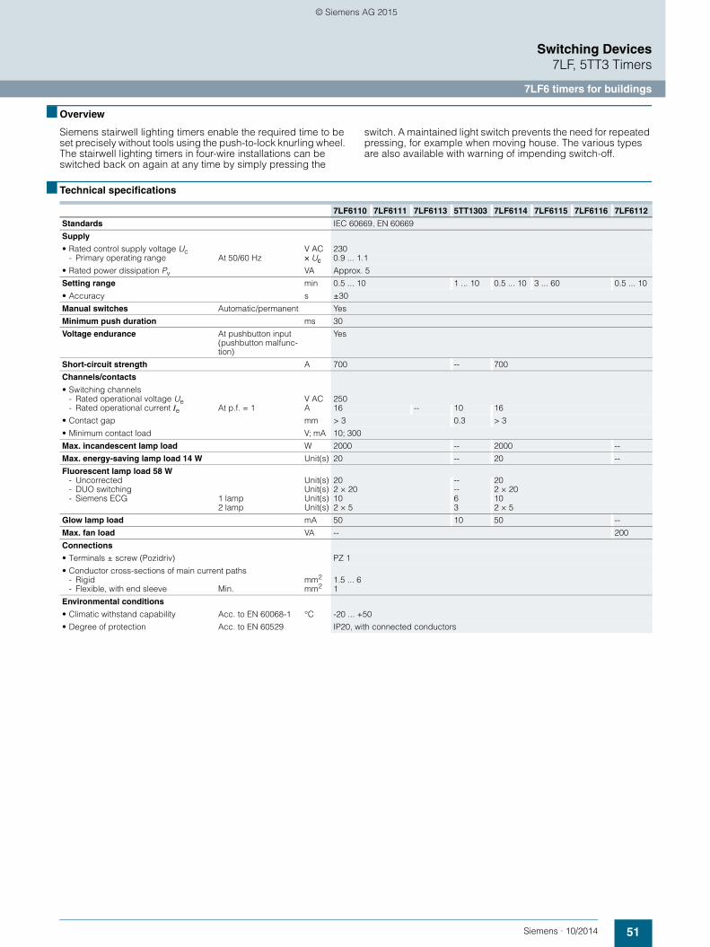
51Siemens · 10/2014
Switching Devices7LF, 5TT3 Timers
7LF6 timers for buildings
■ Overview
Siemens stairwell lighting timers enable the required time to be set precisely without tools using the push-to-lock knurling wheel. The stairwell lighting timers in four-wire installations can be switched back on again at any time by simply pressing the
switch. A maintained light switch prevents the need for repeated pressing, for example when moving house. The various types are also available with warning of impending switch-off.
■ Technical specifications
7LF6110 7LF6111 7LF6113 5TT1303 7LF6114 7LF6115 7LF6116 7LF6112
Standards IEC 60669, EN 60669
Supply
• Rated control supply voltage Uc V AC 230- Primary operating range At 50/60 Hz × Uc 0.9 ... 1.1
• Rated power dissipation Pv VA Approx. 5
Setting range min 0.5 ... 10 1 ... 10 0.5 ... 10 3 ... 60 0.5 ... 10
• Accuracy s ±30
Manual switches Automatic/permanent Yes
Minimum push duration ms 30
Voltage endurance At pushbutton input (pushbutton malfunc-tion)
Yes
Short-circuit strength A 700 -- 700
Channels/contacts
• Switching channels- Rated operational voltage Ue V AC 250- Rated operational current Ie At p.f. = 1 A 16 -- 10 16
• Contact gap mm > 3 0.3 > 3
• Minimum contact load V; mA 10; 300
Max. incandescent lamp load W 2000 -- 2000 --
Max. energy-saving lamp load 14 W Unit(s) 20 -- 20 --
Fluorescent lamp load 58 W- Uncorrected Unit(s) 20 -- 20- DUO switching Unit(s) 2 × 20 -- 2 × 20- Siemens ECG 1 lamp Unit(s) 10 6 10
2 lamp Unit(s) 2 × 5 3 2 × 5
Glow lamp load mA 50 10 50 --
Max. fan load VA -- 200
Connections
• Terminals ± screw (Pozidriv) PZ 1
• Conductor cross-sections of main current paths- Rigid mm2 1.5 ... 6- Flexible, with end sleeve Min. mm2 1
Environmental conditions
• Climatic withstand capability Acc. to EN 60068-1 °C -20 ... +50
• Degree of protection Acc. to EN 60529 IP20, with connected conductors
PH_08.book Seite 51 Dienstag, 27. Januar 2015 11:39 11
© Siemens AG 2015

52 Siemens · 10/2014
7LF6 timers for buildings
Switching Devices7LF, 5TT3 Timers
■ Dimensional drawings
■ Circuit diagrams
Typical circuit for 7LF6111 timer in 4-wire circuit, L-momentary, resettable
Usual circuit for new installation with separate cable routing for pushbuttons and lights. The additional DI switch allows external switching to continuous light or a time switch can also be used for this purpose. An additional attic circuit is also available, which operates independently of the timer, but on the same electrical circuit. The timer can be restarted before the set time expires.
te = runtime
Typical circuit for 7LF6111 time in 3-wire circuit, N-momentary, resettable
Can only be used with a limited number of wires. The timer can be restarted before the set time expires. While this 3-wire circuit with N-momentary contact is technically possible, it does not comply with DIN VDE 0100-460. However, it is used in old systems for replacement purposes.
te = runtime
Typical circuit for 7LF6112 timer for fans up to 200 VA
The switch switches the light on immediately, e.g. in a toilet. After a delay of approx. 1 minute, the fan is switched on. When the light is switched off, the fan continues to run for the time set at the timer.
te = runtime
Typical circuit for 7LF6115 energy-saving timer with prewarning
The timer is connected in the same way as the 7LF6111 timer in a 4-wire or 3-wire circuit. The energy-saving timer is activated at the first press of the button and deactivated at the second press. If it is not switched off manually, it is automatically switched off after the set time, max. 60 minutes. 20 and 40 seconds before expiry, the light flashes briefly twice (50 ms) to warn of the impending tripping. This allows time to reset the switch while the light is still on. Prior to the warning time, a push of the button ends the timing interval.
te = runtime
7LF6110 7LF6111 7LF6112 7LF6113 7LF6114 7LF6115 7LF6116
5TT1303
� �
��
� � �
�
�
�������
7 2444
64
I2_10911
45 67 90 45
2B1B
5
90
6443
--+
1A 31 41
A2
T
36
I201
_067
08
L2
eeet t t I201
_109
16a
N
DEL N
21
L
I201
_109
12a
230 V AC
NL
L N
21
I201
_109
13a
230 V AC
L2eeet t t I2
01_1
0917
a
NL
2 N
L
I201
_109
15a
230 V AC
I201_10918
L21 Min
1 Min v
te
����
����
�
�������� ��������
������� �
������� ���
���
������
PH_08.book Seite 52 Dienstag, 27. Januar 2015 11:39 11
© Siemens AG 2015

53Siemens · 10/2014
Switching Devices7LF, 5TT3 Timers
7LF6 timers for buildings
Typical circuit for 7LF6116 energy-saving timer
The timer is connected in the same way as the 7LF6115 timer in a 4-wire or 3-wire circuit. The energy-saving timer switches on if pressed once and switches off when it is pressed again briefly (less than 1 second).
Resetting is possible by pressing a second time for longer (more than 1 second). If it is not switched off manually, it is automati-cally switched off after the set time, max. 60 minutes.
te = runtime
Lighting in ancillary rooms and corridors
In rooms subject to less frequent use (basements, ironing rooms, attics, heating oil storerooms) there is a risk of the lighting remaining on unnecessarily for lengthy periods. In such cases, the 7LF6115 and 7LF6116 energy-saving timers can consider-ably reduce energy costs while increasing user-friendliness.
Occupants leaving a room can switch off the light by pushbut-ton, just like an installation with remote control switch. In the event that occupants are unable to switch the light off, or simply forget, it will go out automatically after a pre-set time.
The 7LF6115 and 7LF6116 energy-saving timers can also be used in corridors, e.g. as replacements for remote control switches. In this case they combine the familiar functionality of a remote control switch with the energy-saving features of a stairwell lighting timer.
Typical circuit for 7LF6110 timer in 3-wire circuit, L-momentary contact, not resettable
Circuit for new installation with shared cable routing for pushbut-tons and lights. The timer can only be restarted after the set time expires.
te = runtime
Typical circuit for 7LF6113 timer with prewarning
The timer is connected in the same way as the 7LF6111 timer in a 4-wire or 3-wire circuit. 20 and 40 seconds before expiry, the light flashes briefly twice (50 ms) to warn of the impending trip-ping. This allows time to reset the switch while the light is still on.
te = runtime
Typical circuit for 7LF6114 lighting timer with prewarning
The timer is connected in the same way as the 7LF6111 timer in a 4-wire or 3-wire circuit. When pressed, the lighting timer switches on for the set runtime, up to 10 minutes. If the switch is pressed for more than one second, the light is switched on for four times the set time, i.e. up to 40 minutes. The last press of the pushbutton is definitive. 20 and 40 seconds before expiry, the light flashes briefly twice (50 ms) to warn of the impending trip-ping. This allows time to reset the switch while the light is still on. The timing interval restarts each time the button is pressed.
te = runtime
I202_02097UN
L/N
L/2
t<1s t>1s
tet<tet<tete
NL
2 N
L
I201
_109
15a
230 V AC
te
I201_10920
L2
��
�� ������
���������
������
����
����
�
�� ��� �����
�
���� ���� ���
���
������
������ ���
���
������
������
������
PH_08.book Seite 53 Dienstag, 27. Januar 2015 11:39 11
© Siemens AG 2015

54 Siemens · 10/2014
7LF6 timers for buildings
Switching Devices7LF, 5TT3 Timers
Typical circuit for 5TT1303 ECG control switch
The device is fitted with a direct voltage input for the control of an ECG. When the pushbutton is actuated, the power supply is released and the ECG is brightened for up to 10 minutes, depending on the setting of the timer.
On expiry of this time, the ECG is dimmed according to the set dimmer level, if pressed again it brightens again. If no requests are made for 30 minutes (no buttons pressed), the lighting is fully deactivated. In addition to these functions, the dimming time and brightness period can also be controlled using a separate pushbutton or time switch over the control inputs B1 and B2.
Switching the ECG and the fluorescent lamp as little as possible extends the service life.
Hall lighting in nursing home
At meal times, from 5 to 7 p.m., the light in the corridors canbe permanently switched on using a time switch (contact B1). Between 7 p.m. and 10 p.m., the lighting is dimmed using switch B2. Simply press the corridor pushbutton again to return the lighting to the bright setting at any time. After 10 p.m., the light is switched off. It can be switched back on at any time by pressing the corridor pushbutton.
Corridor lighting in hospitals
During the day – i.e. during peak periods, lunch times, visiting times, shift changes, doctor's rounds – the light is switched on. During quiet periods, i.e. afternoons and nights, the light is switched to a dimmed state. A patient can switch the light back to the bright setting at any time by pressing the corridor push-button. In emergencies, the nurse can use a B1 switch to switch to "emergency operation", i.e. permanently bright (no time limit of brightness period).
14
A213 A1
T + -
LN+-
LN+-
LN+-
N
B1 B2
B1 B2I2
01_0
7450
a
L1 230 V AC
t1 t3
t2
13
t1 t3
t2
14
t1
t2
t3
t2
B1
B2
t1
t1 : t2 : t3 :
I201_07691a
Bright phase Operating period Dim phase
PH_08.book Seite 54 Dienstag, 27. Januar 2015 11:39 11
© Siemens AG 2015

55Siemens · 10/2014
Switching Devices7LF, 5TT3 Timers
7LF6 timers for buildings
■ More information
Stairwell lighting
This is required in DIN 18015-2 "Electrical installations in residential buildings; Nature and extent of minimum equipment". What is less known is that 100 lux is required according to EN 12464-1 "Lighting of work places" for interior areas and corridors, section 5.3. This means that approx. 60 W incandes-cent lamps, 25 W energy-saving lamps or 25 W fluorescent lamps need to be used. It is hard to see why lower requirements should apply to stairwells in residential buildings than stipulated in EN 12464-1.
4-wire circuit, L-momentary contact
4 wires are installed within the building. The timing interval is started by pressing phase L. During the runtime, the timer can be reset at all times.
3-wire circuit, L-momentary contact
3 wires are installed within the building. The timing interval is started by pressing phase L. No resetting is possible during the runtime as the pushbutton input and output are exposed to the same potential during this period. The glow lamps are switched off during the runtime.
3-wire circuit, N-momentary contact
3 wires are installed within the building. The timing interval is started by pressing the N conductor. During the runtime, the timer can be reset at all times. However, this switching no longer corresponds to DIN VDE 0100 and is now only used in old systems.
Safety through warning prior to switch-off
DIN 18015-2 "Electrical installations in residential buildings: Nature and extent of minimum equipment" stipulates that the automatic lighting-off control in stairwells of appartment blocks must be equipped with a warning function to prevent sudden darkness in the building. This contribution towards safety is offered by 4 device versions. The 7LF6113 stairwell lighting timer, the 7LF6114 lighting timer and the 7LF6115 energy-saving timer warn of an impending switch-off by flashing, the 5TT1303 stairwell lighting timer ECG warns of an impending switch-off by dimming, allowing sufficient time for the light switch to be pressed again.
Manual switches
All timers have a manual switch for the function "Automatic/ON". This allows the operator to switch to continuous light in the event of moving house or emergencies.
Useful continuous contact
Pushbuttons should never jam. For this reason, all our timers have a safeguard to prevent this type of malfunction. Even better, this feature can be used (e.g. by caretakers of properties) to switch to a continuous light in the event of moving house or emergencies.
Setting accuracy
The electronic remote control switches offer a high degree of accuracy. The runtime can be set precisely to +30 seconds using the push-to-lock knurling wheel setting. The factory settings ensure that the limit values of 1 and 10 or 60 minutes can be reliably set.
Short-circuit strength
Stairwell lighting timers are primarily used for the switching of incandescent lamps, which may occasionally be subject to short circuits. A key feature of all devices is their high short-circuit strength without the contacts welding.
Switching of fluorescent lamps
In order to extend their service life as far as possible, fluorescent lamps should only be switched using a stairwell lighting timer if the switching frequency is not excessive. Using electronic ballast (ECG) to operate them is more gentle on the device and saves energy. The 5TT1303 stairwell lighting timer ECG switches the electronic ballast and warns of the impending switch-off by dimming.
Switching of energy-saving lamps
The switching of energy-saving lamps depends greatly on the lamp type used. Standard energy-saving lamps are generally unsuitable for warning by flashing or dimming prior to switch-off.
The 7LF6110 and 7LF6111 stairwell timers and the 7LF6116energy-saving timers without warning of impending switch-off are suitable for the use of standard energy-saving lamps(e.g. OSRAM DULUX EL).
For applications with warning of impending switch-off(7LF6113 and 7LF6114 stairwell lighting timers or 7LF6115 energy-saving timers) we recommend the use of special energy-saving lamps such as OSRAM DULUX EL FACILITY or OSRAM DULUX EL VARIO.
Download from the Internet:
For more information please visit us on the Internet at: www.siemens.com/lowvoltage
PH_08.book Seite 55 Dienstag, 27. Januar 2015 11:39 11
© Siemens AG 2015

56 Siemens · 10/2014
5TT3 timers for industry
Switching Devices7LF, 5TT3 Timers
■ Overview
Time relays are primarily used in series applications where the use of PLC controls is too labor and cost-intensive. Multifunction
relays with a range of functionalities and clear and intuitive operation are now market standard.
■ Technical specifications
■ Dimensional drawings
■ Circuit diagrams
Graphic symbols
5TT3185 5TT31815TT31825TT3183
5TT3184
Standards EN 60255; DIN VDE 0435-110
Supply
• Rated control supply voltage Uc V AC 12 ... 240 220 ... 240 110 ... 240V DC 12 ... 240 -- 110 ... 240
- Primary operating range × Uc 0.8 ... 1.1
• Rated frequency fn Hz 45 ... 400 50/60
• Rated power dissipation Pv VA Approx. 1.5 Approx. 5 Approx. 1
Setting ranges See setting ranges, timing intervals
Recovery time ms 15 ... 80 Approx. 40 Approx. 100
Contacts
• Switching channels- Rated operational voltage Ue V AC 250- Rated operational current Ie A 4 8 5
• Contact gap mm contact- Minimum contact load V; mA 10; 300
Rated impulse withstand voltage Uimp Input/output kV > 4
Electrical service life In switching cycles 1 A 1.5 × 10⁵ -- 1.5 × 10⁵ At AC-15 -- 1.5 × 10⁵ --
Connections
• Terminals ± screw (Pozidriv) 2
• Conductor cross-sections of main current paths- Rigid, max.- Flexible, with end sleeve, min.
mm2
mm22 × 2.52 × 1.5
Environmental conditions
• Permissible ambient temperature °C -40 ... +60
• Climatic withstand capability Acc. to EN 60068-1 40/60/4
5TT3185 5TT3181 5TT3182 5TT3183 5TT3184
1
2A1B
61 8151A
18
1
2A3Z4Z
61 8151
5Z
A
18
1
2A
61 8151A
18
I201
_065
51
9045
64435
5TT3185 5TT3181 5TT31825TT3183 5TT3184
B1A1
A2 15
16 18MF
Z4A2
1816
15Z3 Z5
A1 18 16
15
A1
A2
PH_08.book Seite 56 Dienstag, 27. Januar 2015 11:39 11
© Siemens AG 2015

57Siemens · 10/2014
Switching Devices7LF, 5TT3 Timers
5TT3 timers for industry
■ More information
5TT3181 delay timer
Response delay
5TT3183 flashing timer
Flashing function
5TT3182 wiper timer
Wiper function
5TT3184 delay-off timer
OFF-delay
Possible time setting ranges tv0.25 s ... 2.5 s1 s ... 10 s8 s ... 80 s
64 s ... 300 s
I201
_070
26
15-1815-16
A1-A2
tVtV = Time delay
Possible joint time setting range of ton = toff = t 1 s ... 10 sI2
01_0
7024
tan
15-1815-16
A1-A2
tab
tan = Relay energizedtab = Relay de-energized
Possible time setting ranges tw1 s ... 10 s
tW
A1-A2
15-1615-18
I201
_070
23
tW= Wiping time
Possible time setting ranges t1 s ... 10 s
t1 = interruption
I201
_070
25
15-1815-16
A1-A2
t
t1
t < t1
t = Drop out delay
PH_08.book Seite 57 Dienstag, 27. Januar 2015 11:39 11
© Siemens AG 2015

58 Siemens · 10/2014
5TT3 timers for industry
Switching Devices7LF, 5TT3 Timers
5TT3185 multifunction timer
Setting aids
The period of the flashing of the green LED 1 when set for a timing interval is 1 s 4%, which can therefore be used as a setting aid. This is particularly useful in the lower time setting range and for long delay times because of the accuracy of the multiplication factors between the individual time ranges.Example:Delay time to be set: 40 min.Using the fine setting, this delay time can be set within the setting range 3 ... 300 min. However, in this case it takes a long time to check the time and requires several operational sequences in realtime. To speed up the setting process, the setting range is switched to 0.03 ... 3 min. In this case, the required value corresponds to a delay time 0.4 min (= 24 s). The timing interval is triggered and the potentiometer is set to 24 flashing periods of the yellow LED 2. The device is then set
back to the setting range 3 ... 300 min and the setting process is completed.
Time operation interruption/time addition
For the functions AV, EW, IE, BI, the timing interval can be interrupted at any time by activating B1 (+) and continued again by removing the control voltage (time addition).
Control input B1
The functions RV, IF, AW, AV/RV can be controlled using the control input B1 (+) with potential against terminal A2. The auxiliary voltage of terminal A1 - or any other voltage within the range 12 ... 240 V AC/DC - can be used for this purpose. The operation of parallel loads (e.g. contactors) from B1 (+) to A2 is also permissible.If voltage is simultaneously applied to the control input B1 (+) and A1 for the IF function, an output pulse is triggered with the set time interval t1.
15-1815-16
t
t
t
t
t
t
t
t
tt tt
ttt
t
tt
15-1815-16
15-1815-16
15-1815-16
15-1815-16
A1-A2
B1-A2
15-1815-16
15-1815-16
15-1815-16
t
0,5 s
1
2
3
4
5
6
7
8
A1-A2
B1-A2
c
St
A1 15
B1
16 18
A2(+)
E1
ZE2
S2
N
(1B 1A 2A+)
L+
S1
N
1A 2A
L+
ContactPosition Functionswitch
Response delay
Pulse generator, delayed
Passing make contact function
Flashing relay,starting with impulse
OFF-delay
Pulse shape
Passing break contact function
Response delayOFF-delay
Control S1
Control S2
AV
EW
IE
BI
RV
IF
AW
AV/RV
Possible time setting ranges t:
LED 1 green
LED 2 yellow
LED 1 green:E1:
LED 2 yellow:Z:
E2:
Status displayTime range adjusterSwitch position indicatorFine adjuster for time rangesFunction setting Timing intervals
Contact S1For the functions: response delay,passing make contact function,pulse generator delayed,clock generator – (start with pulse) –the timing interval is triggered byclosing the switching contact S1.
Control S1
Control contact S2The functions: off-delay,pulse shape, passing break contact function, response and off-delay aretriggered by continuous powersupply over the control contact S2between A1 and B1 (+).
Control S2 User interfacesLED 1 Status displayLED 2 Switching position indicationE1 Setting range adjusterZ Fine adjuster for setting rangesE2 Function settings for timing intervals
Device displaysLED 1 Lights up if operational voltage is applied (green)LED 2 indicates the timing interval and state of the equalizing relay (yellow)• Continuous light- Off output relay not activated, no timing interval- On output relay not activated, no timing interval• Flashing light- Short on, long off Output relay not activated, timing interval- Short on, long off Output relay activated, timing interval
Front viewLED 1 green: Status displayLED 2 yellow: Switching position indicationE1: Setting range adjusterZ: Fine adjuster for setting rangesE2: Function settings for timing intervals
0.020.060.30.030.330.33
I201
_184
44
...
...
...
...
...
...
...
...
16
303
30300
30300
sssminminminhh
PH_08.book Seite 58 Dienstag, 27. Januar 2015 11:39 11
© Siemens AG 2015

© Siemens AG 2015

The information provided in this configuration manual contains merely general descriptions or characteristics of performance which in case of actual use do not always apply as described or which may change as a result of further development of the products. An obligation to provide the respective characteristics shall only exist if expressly agreed in the terms of contract. Availability and technical specifications are subject to change without notice.All product designations may be trademarks or product names of Siemens AG or supplier companies whose use by third parties for their own purposes could violate the rights of the owners.
Siemens AGEnergy ManagementLow Voltage & ProductsPostfach 10 09 5393009 REGENSBURGGERMANY
Subject to change without prior noticePDF (3ZW1012-5TT57-0AC1)PH 0115 58 EnProduced in Germany© Siemens AG 2015
www.siemens.com/lowvoltage
PH_08_10-2014_umschlag_en.indd 2PH_08_10-2014_umschlag_en.indd 2 26.01.2015 12:32:4826.01.2015 12:32:48
© Siemens AG 2015