Configuration Guide for Microsoft Windows Host … 5, Troubleshooting Provides troubleshooting...
92
MK-96RD639-06 Configuration Guide for Microsoft ® Windows ® Host Attachment Hitachi Virtual Storage Platform Hitachi Universal Storage Platform V/VM F ASTF IND L INKS Document Organization Product Version Getting Help Contents
Transcript of Configuration Guide for Microsoft Windows Host … 5, Troubleshooting Provides troubleshooting...

MK-96RD639-06
Configuration Guide for Microsoft® Windows® Host Attachment
Hitachi Virtual Storage Platform Hitachi Universal Storage Platform V/VM
FASTFIND LINKS
Document Organization
Product Version
Getting Help
Contents

ii
Configuration Guide for Microsoft Windows Host Attachment
Copyright © 2010 Hitachi, Ltd., all rights reserved.
No part of this publication may be reproduced or transmitted in any form or by any means, electronic or mechanical, including photocopying and recording, or stored in a database or retrieval system for any purpose without the express written permission of Hitachi, Ltd. (hereinafter referred to as “Hitachi”) and Hitachi Data Systems Corporation (hereinafter referred to as “Hitachi Data Systems”).
Hitachi Data Systems reserves the right to make changes to this document at any time without notice and assumes no responsibility for its use. This document contains the most current information available at the time of publication. When new and/or revised information becomes available, this entire document will be updated and distributed to all registered users.
All of the features described in this document may not be currently available. Refer to the most recent product announcement or contact your local Hitachi Data Systems sales office for information about feature and product availability.
Notice: Hitachi Data Systems products and services can be ordered only under the terms and conditions of the applicable Hitachi Data Systems agreement(s). The use of Hitachi Data Systems products is governed by the terms of your agreement(s) with Hitachi Data Systems.
Hitachi is a registered trademark of Hitachi, Ltd. in the United States and other countries. Hitachi Data Systems is a registered trademark and service mark of Hitachi, Ltd. in the United States and other countries.
All other trademarks, service marks, and company names are properties of their respective owners.
Microsoft product screen shot(s) reprinted with permission from Microsoft Corporation.

Contents iii
Configuration Guide for Microsoft Windows Host Attachment
Contents
Preface................................................................................................... v
Intended Audience ..............................................................................................vi Product Version...................................................................................................vi Document Revision Level .....................................................................................vi Source Documents for this Revision ......................................................................vi Changes in this Revision ..................................................................................... vii Referenced Documents....................................................................................... vii Document Organization ..................................................................................... viii Document Conventions........................................................................................ ix Convention for Storage Capacity Values .................................................................x Accessing Product Documentation .........................................................................x Getting Help .......................................................................................................xi Comments ..........................................................................................................xi
Introduction......................................................................................... 1-1
About the Hitachi RAID Storage Systems.............................................................1-2 Device Types ....................................................................................................1-3 Host Attachment Roadmap ................................................................................1-7
Installing the Storage System................................................................ 2-1
Requirements ...................................................................................................2-2 Preparing for Host Attachment ...........................................................................2-3
Installing the Hitachi RAID Storage System Hardware....................................2-3 Setting the System Option Modes ................................................................2-4 Installing the LUN Manager Software ...........................................................2-4 Setting the Host Modes ...............................................................................2-5 Setting the Host Mode Options ....................................................................2-6 Configuring the Fibre-Channel Ports .............................................................2-7
Port Address Considerations for Fabric Environments ..............................2-8 Loop ID Conflicts .................................................................................2-9

iv Contents
Configuration Guide for Microsoft Windows Host Attachment
Connecting to the Windows Host ..................................................................... 2-10 Disk Number Assignments ........................................................................ 2-12
Configuring the Host Fibre-Channel HBA(s)....................................................... 2-14 Verifying the Disk and Device Parameters......................................................... 2-16
Verifying the Disk I/O Timeout Value (TOV) ............................................... 2-16 Verifying the Queue Depth ....................................................................... 2-18
Configuring the New Disk Devices.......................................................... 3-1
Writing the Signatures ...................................................................................... 3-2 Creating and Formatting the Partitions ............................................................... 3-5 Verifying File System Operations...................................................................... 3-10 Verifying Auto-Mount ...................................................................................... 3-13 Changing the Enable Write Caching Option....................................................... 3-14
Failover and SNMP Operations............................................................... 4-1
Host Failover.................................................................................................... 4-2 Path Failover.................................................................................................... 4-3 Windows 2008 MPIO Configuration Procedure .................................................... 4-4
Enabling MultiPath IO................................................................................. 4-4 SNMP Remote System Management................................................................. 4-11
Troubleshooting ................................................................................... 5-1
General Troubleshooting ................................................................................... 5-2 Calling the Hitachi Data Systems Support Center................................................. 5-3
SCSI TID Maps for FC Adapters ............................................................. A-1
Creating an Online LUSE Volume ........................................................... B-1
Acronyms and Abbreviations

Preface v
Configuration Guide for Microsoft Windows Host Attachment
Preface
This document describes and provides instructions for installing and configuring the devices on the Hitachi RAID storage systems for operations in a Microsoft® Windows® environment. The Hitachi RAID storage system models include the Hitachi Virtual Storage Platform (VSP) and the Hitachi Universal Storage Platform V and Hitachi Universal Storage Platform VM (USP V/VM).
Please read this document carefully to understand how to use this product, and maintain a copy for reference purposes.
This preface includes the following information:
Intended Audience
Product Version
Document Revision Level
Source Documents for this Revision
Changes in this Revision
Referenced Documents
Document Organization
Document Conventions
Convention for Storage Capacity Values
Getting Help
Comments

vi Preface
Configuration Guide for Microsoft Windows Host Attachment
Intended Audience This document is intended for system administrators, Hitachi Data Systems representatives, and authorized service providers who are involved in installing, configuring, and operating the Hitachi RAID storage systems.
Readers of this document should meet the following requirements:
• You should have a background in data processing and understand RAID storage systems and their basic functions.
• You should be familiar with the Hitachi RAID storage system(s), and you should have read the User and Reference Guide for the storage system.
• You should be familiar with the Storage Navigator software for the Hitachi RAID storage system(s), and you should have read the Storage Navigator User’s Guide.
• You should be familiar with the Microsoft Windows operating system and the hardware hosting the Microsoft Windows system.
• You should be familiar with the hardware used to attach the Hitachi RAID storage system to the Microsoft Windows host, including fibre-channel cabling, host bus adapters (HBAs), switches, and hubs.
Product Version
This document revision applies to the following microcode levels:
• Hitachi Virtual Storage Platform microcode 70-01-0x or later.
• Hitachi Universal Storage Platform V/VM microcode 60-03-2x or later.
Document Revision Level
Revision Date Description
MK-96RD639-P February 2007 Preliminary Release
MK-96RD639-00 May 2007 Initial Release, supersedes and replaces MK-96RD639-P
MK-96RD639-01 September 2007 Revision 1, supersedes and replaces MK-96RD639-00
MK-96RD639-02 May 2008 Revision 2, supersedes and replaces MK-96RD639-01
MK-96RD639-03 August 2008 Revision 3, supersedes and replaces MK-96RD639-02
MK-96RD639-04 November 2009 Revision 4, supersedes and replaces MK-96RD639-03
MK-96RD639-05 January 2010 Revision 5, supersedes and replaces MK-96RD639-04
MK-96RD639-06 October 2010 Revision 6, supersedes and replaces MK-96RD639-05
Source Documents for this Revision • MK-96RD639-05b-1_RSDreview

Preface vii
Configuration Guide for Microsoft Windows Host Attachment
Changes in this Revision • Added the Hitachi Virtual Storage Platform storage system.
• Added information about the 8-Gbps fibre-channel interface (Table 2-1).
• Added a link to the Hitachi Data Systems interoperability matrix for specific information about supported OS versions, HBAs, drivers, hubs, and switches (Table 2-1).
Referenced Documents
Hitachi Virtual Storage Platform documentation:
• Provisioning Guide for Open Systems, MK-90RD7022
• Storage Navigator User Guide, MK-90RD7027
• Storage Navigator Messages, MK-90RD7028
• User and Reference Guide, MK-90RD7042
Hitachi Universal Storage Platform V/VM documentation:
• Storage Navigator Messages, MK-96RD613
• LUN Manager User’s Guide, MK-96RD615
• LUN Expansion User’s Guide, MK-96RD616
• Storage Navigator User’s Guide, MK-96RD621
• Virtual LVI/LUN and Volume Shredder User’s Guide, MK-96RD630
• User and Reference Guide, MK-96RD635
• Hitachi Cross-OS File Exchange User’s Guide, MK-96RD647
• Hitachi Dynamic Link Manager for Windows User’s Guide, MK-92DLM129
Microsoft Windows documentation

viii Preface
Configuration Guide for Microsoft Windows Host Attachment
Document Organization
The following table provides an overview of the contents and organization of this document. Click the chapter title in the left column to go to that chapter. The first page of each chapter provides links to the sections in that chapter.
Chapter Description
Chapter 1, Introduction Provides a brief overview of the Hitachi RAID storage systems, the Microsoft Windows host, and the installation procedure.
Chapter 2, Installing the Storage System
Provides instructions for installing and connecting the Hitachi RAID storage systems to a Microsoft Windows host.
Chapter 3, Configuring the New Disk Devices
Provides instructions for configuring the new devices on the Hitachi RAID storage systems for use.
Chapter 4, Failover and SNMP Operations
Describes how to configure the Hitachi RAID storage systems for failover and SNMP.
Chapter 5, Troubleshooting Provides troubleshooting information for Windows host attachment.
Appendix A, SCSI TID Maps for FC Adapters
Describes SCSI TID maps for fibre-channel adapters.
Appendix B, Creating an Online LUSE Volume
Provides instructions for expanding a LUSE volume in an online Windows operating system.

Preface ix
Configuration Guide for Microsoft Windows Host Attachment
Document Conventions
The terms “Virtual Storage Platform” and “VSP” refer to all models of the Hitachi Virtual Storage Platform storage system, unless otherwise noted.
The terms “Universal Storage Platform V” and “Universal Storage Platform VM” refer to all models of the Hitachi Universal Storage Platform V and VM storage systems, unless otherwise noted.
This document uses the following typographic conventions:
Convention Description
Bold Indicates text on a window, other than the window title, including menus, menu options, buttons, fields, and labels. Example: Click OK.
Italic Indicates a variable, which is a placeholder for actual text provided by the user or system. Example: copy source-file target-file
Note: Angled brackets (< >) are also used to indicate variables.
screen/code Indicates text that is displayed on screen or entered by the user. Example: # pairdisplay -g oradb
< > angled brackets Indicates a variable, which is a placeholder for actual text provided by the user or system. Example: # pairdisplay -g <group>
Note: Italic font is also used to indicate variables.
[ ] square brackets Indicates optional values. Example: [ a | b ] indicates that you can choose a, b, or nothing.
{ } braces Indicates required or expected values. Example: { a | b } indicates that you must choose either a or b.
| vertical bar Indicates that you have a choice between two or more options or arguments. Examples:
[ a | b ] indicates that you can choose a, b, or nothing.
{ a | b } indicates that you must choose either a or b.
underline Indicates the default value. Example: [ a | b ]
This document uses the following icons to draw attention to information:
Icon Meaning Description
Note Calls attention to important and/or additional information.
Tip Provides helpful information, guidelines, or suggestions for performing tasks more effectively.
Caution Warns the user of adverse conditions and/or consequences (e.g., disruptive operations).
WARNING Warns the user of severe conditions and/or consequences (e.g., destructive operations).

x Preface
Configuration Guide for Microsoft Windows Host Attachment
Convention for Storage Capacity Values
Physical storage capacity values (e.g., disk drive capacity) are calculated based on the following values:
Physical capacity unit Value
1 KB 1,000 (103) bytes
1 MB 1,000 KB or 1,0002 bytes
1 GB 1,000 MB or 1,0003 bytes
1 TB 1,000 GB or 1,0004 bytes
1 PB 1,000 TB or 1,0005 bytes
1 EB 1,000 PB or 1,0006 bytes
Logical storage capacity values (e.g., logical device capacity) are calculated based on the following values:
Logical capacity unit Value
1 block 512 bytes
1 KB 1,024 (210) bytes
1 MB 1,024 KB or 1,0242 bytes
1 GB 1,024 MB or 1,0243 bytes
1 TB 1,024 GB or 1,0244 bytes
1 PB 1,024 TB or 1,0245 bytes
1 EB 1,024 PB or 1,0246 bytes
Accessing Product Documentation
The user documentation for the Hitachi RAID storage systems is available on the Hitachi Data Systems Portal: https://hdssupport.hds.com. Check this site for the most current documentation, including important updates that may have been made after the release of the product.

Preface xi
Configuration Guide for Microsoft Windows Host Attachment
Getting Help
The Hitachi Data Systems customer support staff is available 24 hours a day, seven days a week. If you need technical support, log on to the Hitachi Data Systems Portal for contact information: https://hdssupport.hds.com
Comments
Please send us your comments on this document: [email protected]. Include the document title, number, and revision, and refer to specific section(s) and paragraph(s) whenever possible.
Thank you! (All comments become the property of Hitachi Data Systems.)

xii Preface
Configuration Guide for Microsoft Windows Host Attachment

1
Introduction 1-1
Configuration Guide for Microsoft Windows Host Attachment
Introduction
This chapter provides an overview of the Hitachi RAID storage systems and host attachment:
About the Hitachi RAID Storage Systems
Device Types
Host Attachment Roadmap

1-2 Introduction
Configuration Guide for Microsoft Windows Host Attachment
About the Hitachi RAID Storage Systems
The Hitachi RAID storage systems offer a wide range of storage and data services, including thin provisioning with Hitachi Dynamic Provisioning™ software, application-centric storage management and logical partitioning, and simplified and unified data replication across heterogeneous storage systems. These storage systems are an integral part of the Services Oriented Storage Solutions architecture from Hitachi Data Systems, providing the foundation for matching application requirements to different classes of storage and delivering critical services such as:
• Business continuity services
• Content management services (search, indexing)
• Non-disruptive data migration
• Volume management across heterogeneous storage arrays
• Thin provisioning
• Security services (immutability, logging, auditing, data shredding)
• Data de-duplication
• I/O load balancing
• Data classification
• File management services
The Hitachi RAID storage systems provide heterogeneous connectivity to support multiple concurrent attachment to a variety of host operating systems, including Windows® as well as VMware™, UNIX®, Linux®, and mainframe servers, enabling massive consolidation and storage aggregation across disparate platforms. The storage systems can operate with multi-host applications and host clusters, and are designed to handle very large databases as well as data warehousing and data mining applications that store and retrieve terabytes of data.
The Hitachi RAID storage systems are configured with OPEN-V logical units (LUs) and are compatible with most fibre-channel (FC) host bus adapters (HBAs). Users can perform additional LU configuration activities using the LUN Manager, Virtual LVI/LUN (VLL), and LUN Expansion (LUSE) features provided by the Storage Navigator software, which is the primary user interface for the storage systems.
For further information on storage solutions and the Hitachi RAID storage systems, please contact your Hitachi Data Systems account team.

Introduction 1-3
Configuration Guide for Microsoft Windows Host Attachment
Device Types
Table 1-1 describes the types of logical devices (volumes) that can be installed and configured for operation with the Hitachi RAID storage system on a Microsoft Windows operating system. Table 1-2 lists the specifications for devices supported by the Hitachi RAID storage system. Logical devices are defined to the host as SCSI disk devices, even though the interface is fibre channel. For information about configuring devices other than OPEN-V, contact your Hitachi Data Systems representative.
The sector size for the devices is 512 bytes.
Table 1-1 Logical Devices Supported by the Hitachi RAID storage systems
Device Type Description
OPEN-V Devices OPEN-V logical units (LUs) are disk devices (VLL-based volumes) that do not have a predefined size.
OPEN-x Devices The OPEN-x logical units (LUs) (e.g., OPEN-3, OPEN-9) are disk devices of predefined sizes. Hitachi RAID storage system supports OPEN-3, OPEN-8, OPEN-9, OPEN-E, and OPEN-L devices. For information on usage of these device types, please contact your Hitachi Data Systems account team.
LUSE Devices (OPEN-x*n)
LUSE devices are combined LUs that can be from 2 to 36 times larger than standard OPEN-x LUs. Using LUN Expansion (LUSE) remote console software, you can configure these custom-size devices. LUSE devices are designated as OPEN-x*n, where x is the LU type (e.g., OPEN-9*n) and 2< n < 36). For example, a LUSE device created from 10 OPEN-3 LUs is designated as an OPEN-3*10 disk device. This lets the host combine logical devices and access the data stored on the Hitachi RAID storage system using fewer LU numbers.
VLL Devices (OPEN-x VLL)
VLL devices are custom-size LUs that are smaller than standard OPEN-x LUs. Using Virtual LVI/LUN remote console software, you can configure VLL devices by “slicing” a single LU into several smaller LUs that best fit your application needs to improve host access to frequently used files. The product name for the OPEN-x VLL devices is OPEN-x-CVS (CVS stands for custom volume size). The OPEN-L LU type does not support Virtual LVI/LUN.
VLL LUSE Devices (OPEN-x*n VLL)
VLL LUSE devices combine Virtual LVI/LUN devices (instead of standard OPEN-x LUs) into LUSE devices. Use the Virtual LVI/LUN feature to create custom-size devices, then use the LUSE feature to combine the VLL devices. You can combine from 2 to 36 VLL devices into one VLL LUSE device. For example, an OPEN-3 LUSE volume created from a0 OPEN-3 VLL volumes is designated as an OPEN-3*10 VLL device (product name OPEN-3*10-CVS).
FX Devices (3390-3A/B/C, OPEN-x-FXoto)
The Hitachi Cross-OS File Exchange (FX) feature allows you to share data across mainframe, UNIX, and PC server platforms using special multiplatform volumes. The VLL feature can be applied to FX devices for maximum flexibility in volume size.
FX devices are not SCSI disk devices, and must be installed and accessed as raw devices. Windows hosts must use FX to access the FX devices as raw devices (no file system, no mount operation).
The 3390-3B devices are write-protected from Windows host access. The Hitachi RAID storage system rejects all Windows host write operations (including fibre-channel adapters) for 3390-3B devices.
The 3390-3A/C and OPEN-x-FXoto devices are not write-protected for Windows host access. Do not execute any write operations on these devices. Do not create a partition or file system on these devices. This will overwrite data on the FX device and prevent the FX software from accessing the device.
For more information about FX, see the Hitachi Cross-OS File Exchange User’s Guide, or contact your Hitachi Data Systems account team.

1-4 Introduction
Configuration Guide for Microsoft Windows Host Attachment
Table 1-2 Device Specifications
Device Type (Note 1)
Category (Note 2)
Product Name (Note 3)
# of Blocks (512 B/blk)
# of Cylinders
# of Heads
# of Sectors per Track
Capacity (MB)
(Note 4)
OPEN-3 SCSI disk OPEN-3 4806720 3338 15 96 2347
OPEN-8 SCSI disk OPEN-8 14351040 9966 15 96 7007
OPEN-9 SCSI disk OPEN-9 14423040 10016 15 96 7042
OPEN-E SCSI disk OPEN-E 28452960 19759 15 96 13893
OPEN-L SCSI disk OPEN-L 71192160 49439 15 96 34761
OPEN-3*n SCSI disk OPEN-3*n 4806720*n 3338*n 15 96 2347*n
OPEN-8*n SCSI disk OPEN-8*n 14351040*n 9966*n 15 96 7007*n
OPEN-9*n SCSI disk OPEN-9*n 14423040*n 10016*n 15 96 7042*n
OPEN-E*n SCSI disk OPEN-E*n 28452960*n 19759*n 15 96 13893*n
OPEN-L*n SCSI disk OPEN-L*n 71192160*n 49439*n 15 96 34761*n
OPEN-3 VLL SCSI disk OPEN-3-CVS Note 5 Note 6 15 96 Note 7
OPEN-8 VLL SCSI disk OPEN-8-CVS Note 5 Note 6 15 96 Note 7
OPEN-9 VLL SCSI disk OPEN-9-CVS Note 5 Note 6 15 96 Note 7
OPEN-E VLL SCSI disk OPEN-E-CVS Note 5 Note 6 15 96 Note 7
OPEN-V VLL SCSI disk OPEN-V Note 5 Note 6 15 128 Note 7
OPEN-3*n VLL SCSI disk OPEN-3*n-CVS Note 5 Note 6 15 96 Note 7
OPEN-8*n VLL SCSI disk OPEN-8*n-CVS Note 5 Note 6 15 96 Note 7
OPEN-9*n VLL SCSI disk OPEN-9*n-CVS Note 5 Note 6 15 96 Note 7
OPEN-E*n VLL SCSI disk OPEN-E*n-CVS Note 5 Note 6 15 96 Note 7
OPEN-V*n VLL SCSI disk OPEN-V*n Note 5 Note 6 15 128 Note 7
3390-3A FX otm/mto 3390-3A 5820300 3345 15 116 2844
3390-3B FXmto 3390-3B 5816820 3343 15 116 2844
3390-3C FXotm OP-C-3390-3C 5820300 3345 15 116 2844
FX OPEN-3 FXoto OPEN-3 4806720 3338 15 96 2347
3390-3A VLL FX otm/mto 3390-3A-CVS Note 5 Note 6 15 116 Note 7
3390-3B VLL FXmto 3390-3B-CVS Note 5 Note 6 15 116 Note 7
3390-3C VLL FXotm OP-C-3390-3C-CVS Note 5 Note 6 15 116 Note 7
FX OPEN-3 VLL FXoto OPEN-3-CVS Note 5 Note 6 15 96 Note 7
Note 1: The availability of specific device types depends on the storage system model and the level of microcode installed on the storage system.

Introduction 1-5
Configuration Guide for Microsoft Windows Host Attachment
Note 2: The category of a device (SCSI disk or FX) determines its volume usage. Table 1-3 shows the volume usage for SCSI disk and FX devices:
• The SCSI disk devices (OPEN-V, VLL, LUSE, and VLL LUSE) are usually formatted with file systems for Windows operations.
• The FX devices (3390-3A/B/C, and OPEN-x-FXoto) must be installed as raw devices and can only be accessed using the FX software. Do not partition or create a file system on any device used for FX operations. Do not write a signature on an FX device unless used in an MSCS environment.
Table 1-3 Volume Usage for Device Categories
Category Device Type Volume Usage
SCSI Disk OPEN-x, OPEN-x VLL, OPEN-x*n LUSE, OPEN-x*n VLL LUSE
File System or Raw Device (e.g., some applications use raw devices)
FX 3390-3A/B/C 3390-3A/B/C VLL OPEN-x for FXoto, OPEN-x VLL for FXoto
Raw Device
Note 3: The command device (used for Command Control Interface (CCI) operations) is distinguished by –CM on the product name (e.g., OPEN-3-CM, OPEN-3-CVS-CM). The product name for VLL devices is OPEN-x-CVS, where CVS = custom volume size.
Note 4: This capacity is the maximum size which can be entered using the lvcreate command. The device capacity can sometimes be changed by the BIOS or host bus adapter. Also, different capacities may be due to variations such as 1 MB = 10002 or 10242 bytes.
Note 5: The number of blocks for a VLL volume is calculated as follows:
# of blocks = (# of data cylinders) × (# of heads) × (# of sectors per track)
The number of sectors per track is 128 for OPEN-V and 96 for the other emulation types.
Example: For an OPEN-3 VLL volume with capacity = 37 MB:
# of blocks = (53 cylinders – see Note 3) × (15 heads) × (96 sectors per track) = 76320

1-6 Introduction
Configuration Guide for Microsoft Windows Host Attachment
Note 6: The number of data cylinders for a Virtual LVI/LUN volume is calculated as follows (↑…↑ means that the value should be rounded up to the next integer):
• Number of data cylinders for OPEN-x VLL volume (except for OPEN-V) = # of cylinders = ↑ (capacity (MB) × 1024/720 ↑
Example: For OPEN-3 VLL volume with capacity = 37 MB:
# of cylinders = ↑37 × 1024/720↑ = ↑52.62↑ = 53 cylinders
• Number of data cylinders for an OPEN-V VLL volume = # of cylinders = ↑ (capacity (MB) specified by user) × 16/15 ↑
Example: For OPEN-V VLL volume with capacity = 50 MB:
# of cylinders = ↑50 × 16/15↑ = ↑53.33↑ = 54 cylinders
• Number of data cylinders for a VLL LUSE volume (except for OPEN-V) = # of cylinders = ↑ (capacity (MB) × 1024/720 ↑ × n
Example: For OPEN-3 VLL LUSE volume with capacity = 37 MB and n = 4:
# of cylinders = ↑37 × 1024/720↑ × 4 = ↑52.62↑ × 4 = 53 × 4 = 212
• Number of data cylinders for an OPEN-V VLL LUSE volume = # of cylinders = ↑ (capacity (MB) specified by user) × 16/15 ↑ × n
Example: For OPEN-V VLL LUSE volume with capacity = 50 MB and n = 4:
# of cylinders = ↑50 × 16/15↑ × 4 = ↑53.33↑× 4 = 54 × 4 = 216
• Number of data cylinders for a 3390-3A/C = # of cylinders = (number of cylinders) + 9
• Number of data cylinders for a 3390-3B VLL volume = # of cylinders = (number of cylinders) + 7
Note 7: The size of an OPEN-x VLL volume is specified by capacity in MB, not number of cylinders. The size of an OPEN-V VLL volume can be specified by capacity in MB or number of cylinders. The user specifies the volume size using the Virtual LVI/LUN software.

Introduction 1-7
Configuration Guide for Microsoft Windows Host Attachment
Host Attachment Roadmap
The steps in Table 1-4 outline the general process for attaching the Hitachi RAID storage system to a Microsoft Windows host server.
Table 1-4 Host Attachment Roadmap
Step Task
1. Verify that the host to which you are attaching the Hitachi RAID storage system meets the requirements.
2. Prepare the Hitachi RAID storage system for host attachment.
3. Connect the Hitachi RAID storage system to the Windows host.
4. Configure the fibre-channel (FC) host bus adapters (HBAs).
5. Verify disk and device parameters.
6. Write the signatures and create and format the partitions on the new disk devices.
7. Verify file system operations and auto-mount of the new logical devices.
8. Change the “Enable Write Caching on Disk” option.

1-8 Introduction
Configuration Guide for Microsoft Windows Host Attachment

2
Installing the Storage System 2-1
Configuration Guide for Microsoft Windows Host Attachment
Installing the Storage System
This chapter describes how to install the Hitachi RAID storage system on a Microsoft Windows operating system:
Requirements
Preparing for Host Attachment
Connecting to the Windows Host
Configuring the Host Fibre-Channel HBA(s)
Verifying the Disk and Device Parameters

2-2 Installing the Storage System
Configuration Guide for Microsoft Windows Host Attachment
Requirements Table 2-1 lists and describes the requirements for installing the Hitachi RAID storage system on the Windows operating system.
Table 2-1 Requirements
Requirements Description
Hitachi RAID storage system
The availability of features and devices depends on the level of microcode installed on the Hitachi RAID storage system.
The LUN Manager software on Storage Navigator is used to configure the fibre-channel ports.
Windows server or workstation
Refer to the Microsoft user documentation for PC server hardware requirements.
Windows operating system
Please refer to the Hitachi Data Systems interoperability matrix for specific support information for the Windows operating system: http://www.hds.com/products/interoperability
Fibre-channel HBAs The Hitachi RAID storage system supports fibre-channel HBAs equipped as follows:
8-Gbps fibre-channel interface, including shortwave non-OFC (open fibre control) optical interface and multimode optical cables with LC connectors.
4 Gbps FC interface, including shortwave non-OFC optical interface and multimode optical cables with LC connectors.
2 Gbps FC interface, including shortwave non-OFC optical interface and multimode optical cables with LC connectors.
1 Gbps FC interface, including shortwave non-OFC optical interface and multimode optical cables with SC connectors.
If a switch or HBA with a 1 Gbps transfer rate is used, configure the device to use a fixed 1 Gbps setting instead of Auto Negotiation. Otherwise, it may prevent a connection from being established.
However, the transfer speed of CHF port cannot be set as 1 Gbps when the CHF is 8US/8UFC/16UFC. Therefore 1 Gbps HBA and switch cannot be connected.
Do not connect OFC-type fibre-channel interfaces to the Hitachi RAID storage system.
For information about supported fibre-channel adapters, cables, hubs, and switches, refer to the Hitachi Data Systems interoperability matrix: http://www.hds.com/products/interoperability
Fibre-channel utilities and tools
Refer to the documentation for your fibre-channel HBA for information about installing the utilities and tools for your adapter.
Fibre-channel drivers Do not install/load the driver(s) yet. When instructed in this guide to install the drives for your fibre-channel HBA, refer to the documentation for your adapter.

Installing the Storage System 2-3
Configuration Guide for Microsoft Windows Host Attachment
Preparing for Host Attachment
This section describes the tasks that must be performed before attaching the Hitachi RAID storage system to the host:
• Installing the Hitachi RAID Storage System Hardware
• Setting the System Option Modes
• Installing the LUN Manager Software
• Setting the Host Mode Options
• Configuring the Fibre-Channel Ports
Installing the Hitachi RAID Storage System Hardware
The Hitachi Data Systems representative performs the hardware installation by following the precautions and procedures in the Maintenance Manual for the storage system.
Hardware installation activities include:
• Assembling all hardware and cabling.
• Installing and formatting the logical devices (LDEVs). Be sure to obtain the desired LDEV configuration information from the user, including the desired number of OPEN-x, LUSE, VLL, VLL LUSE, and multiplatform (FX) devices.
• Installing the fibre-channel HBAs and cabling. The total fibre cable length attached to each fibre-channel adapter must not exceed 500 meters (1,640 feet).
– Do not connect any OFC-type connectors to the Hitachi RAID storage system.
– Do not connect/disconnect fibre-channel cabling that is being actively used for I/O. This can cause the Windows system to hang.
– Always confirm that the devices on the fibre cable are offline before connecting/disconnecting the fibre cable.
• Configuring the fibre port topology. The fibre topology parameters for each fibre-channel port on the storage system depend on the type of device to which the port is connected, and the type of port. Determine the topology parameters supported by the device, and set your topology accordingly (see Configuring the USP V/VM Fibre-Channel Ports).
Before starting the installation, check all specifications to ensure proper installation and configuration.

2-4 Installing the Storage System
Configuration Guide for Microsoft Windows Host Attachment
Setting the System Option Modes
To provide greater flexibility and enable the Hitachi RAID storage system to be tailored to unique customer operating requirements, additional operational parameters called “system option modes” are available. At installation, the system option modes are set to their default values. The system option modes are set on the service processor (SVP) and can only be changed by the Hitachi Data Systems representative.
To ensure that the appropriate system option modes are set:
1. Review the system option modes for your storage system model. The system option modes are listed and described in the User and Reference Guide for your storage system model:
– Hitachi VSP User and Reference Guide, MK-90RD7042
– Hitachi USP V/VM User and Reference Guide, MK-96RD635
2. Discuss the system option modes with your Hitachi Data Systems representative, and ask the representative to set the system option modes that apply to your configuration and environment.
Installing the LUN Manager Software
The LUN Manager software on Storage Navigator is used to configure the fibre-channel ports on the Hitachi RAID storage system. The user or Hitachi Data Systems representative installs the LUN Manager software.
For instructions on installing LUN Manager, see the Storage Navigator User’s Guide for the storage system.
For instructions on using LUN Manager on the Hitachi USP V/VM, see the LUN Manager User’s Guide. For instructions on using LUN Manager on the Hitachi VSP, see the Provisioning Guide for Open Systems.

Installing the Storage System 2-5
Configuration Guide for Microsoft Windows Host Attachment
Setting the Host Modes
You can connect multiple server hosts of different platforms to a single port, but you must group server hosts connected to the storage system by host groups, which are segregated by platform. For example, if both Windows and VMware hosts are connected to a single port, you must first create a separate host group for each platform, and then register the hosts to the corresponding host group. When you create a host group, you need to set the host mode and host mode options for the group.
Use Storage Navigator to create host groups, register hosts in host groups, and set host modes and host mode options. For the VSP storage system, see the Provisioning Guide for Open Systems for instructions. For the USP V/VM storage system, see the LUN Manager User’s Guide for instructions.
The required host mode for Windows is 0C or 2C Windows Extension. Do not select a host mode other than 0C or 2C for Windows. Either setting is required to support MSCS failover and to recognize more than eight LUs.
If you plan to create LUSE volumes, use host mode 2C Windows Extension. If you plan to create a LUSE volume using a volume to which an LU path has already been defined, you must use host mode 2C Windows Extension.
WARNING: Changing host modes on a Hitachi RAID storage system that is already installed and configured is disruptive and requires the server to be rebooted.

2-6 Installing the Storage System
Configuration Guide for Microsoft Windows Host Attachment
Setting the Host Mode Options
When each new host group is added, the storage administrator must make sure that the host mode options (HMOs) are set for all host groups connected to Windows hosts. Use the LUN Manager software on Storage Navigator to set the HMOs.
Table 2-2 lists the HMOs for Windows and specifies the conditions for selecting the appropriate HMOs for your installation. Note that host mode option 13 is common to all platforms.
WARNING: Changing HMOs on a Hitachi RAID storage system that is already installed and configured is disruptive and requires the server to be rebooted.
Table 2-2 Host Mode Options for Windows Operations
HMO Function Description Remarks
2 Veritas Database Edition™/ Advanced Cluster
Select HMO 2 if you are using either:
Veritas Database Edition™/Advanced Cluster for Real Application Clusters, or
Veritas Cluster Server™ 4.0 or later (I/O fencing function).
Mandatory. Do not apply this option to Sun™ Cluster.
6 TPRLO Select HMO 6 when all of the following conditions are satisfied:
You are using host mode 0C Windows or 2C Windows Extension, and
You are using the Emulex® host bus adapter and mini-port driver, and
You specify TPRLO=2 for the host bus adaptor mini-port driver.
Optional
13 SIM report at link failure
Select HMO 13 when you want SIM notification when the number of link failures detected between ports exceeds the threshold.
Optional
This mode is common to all host platforms.
40 V-Vol expansion
Select HMO 40 when all of the following conditions are satisfied:
The host mode 0C Windows or 2C Windows Extension is used
You want to automate recognition of the DP-VOL capacity after increasing the DP-VOL capacity.
Optional

Installing the Storage System 2-7
Configuration Guide for Microsoft Windows Host Attachment
Configuring the Fibre-Channel Ports
The LUN Manager software is used to configure the fibre-channel ports with the appropriate fibre parameters. You select the appropriate settings for each fibre-channel port based on the device to which the port is connected. Determine the topology parameters supported by the device, and set your topology accordingly.
Figure 2-1 shows the LUN Manager window for defining port parameters, and Table 2-3 explains the settings on the window.
Table 2-3 Fibre Parameter Settings
Fabric Connection Provides
Enable FC-AL FL-port (Fabric port)
Enable Point-to-Point F-port (Fabric port)
Disable FC-AL NL-port (Private arbitrated loop)
Disable Point-to-Point Not supported
Note: • If you plan to connect different types of servers to the a Hitachi RAID
storage system via the same fabric switch, use the zoning function of the fabric switch.
• Contact Hitachi Data Systems for information about port topology configurations supported by HBA/switch combinations. Not all switches support F-port connection.

2-8 Installing the Storage System
Configuration Guide for Microsoft Windows Host Attachment
Figure 2-1 Setting FC Port Parameters (USP V/VM shown)
Port Address Considerations for Fabric Environments
In fabric environments, port addresses are assigned automatically by fabric switch port number and are not controlled by the port settings on the storage system. In arbitrated loop environments, the port addresses are set by entering an AL-PA (arbitrated-loop physical address, or loop ID). See Appendix A: SCSI TID Maps for FC Adapters for a description of the AL-PA-to-TID translation.
1Table 2-4 shows the available AL-PA values ranging from 01 to EF. Fibre-channel protocol uses the AL-PAs to communicate on the fibre-channel link, but the software driver of the platform host adapter translates the AL-PA value assigned to the port to a SCSI TID.

Installing the Storage System 2-9
Configuration Guide for Microsoft Windows Host Attachment
Table 2-4 Available AL-PA Values
EF CD B2 98 72 55 3A 25
E8 CC B1 97 71 54 39 23
E4 CB AE 90 6E 53 36 1F
E2 CA AD 8F 6D 52 35 1E
E1 C9 AC 88 6C 51 34 1D
E0 C7 AB 84 6B 4E 33 1B
DC C6 AA 82 6A 4D 32 18
DA C5 A9 81 69 4C 31 17
D9 C3 A7 80 67 4B 2E 10
D6 BC A6 7C 66 4A 2D 0F
D5 BA A5 7A 65 49 2C 08
D4 B9 A3 79 63 47 2B 04
D3 B6 9F 76 5C 46 2A 02
D2 B5 9E 75 5A 45 29 01
D1 B4 9D 74 59 43 27
CE B3 9B 73 56 3C 26
Loop ID Conflicts
The Microsoft Windows operating system assigns port addresses from lowest (01) to highest (EF). To avoid loop ID conflict, assign the port addresses from highest to lowest (i.e., starting at EF). The AL-PAs should be unique for each device on the loop to avoid conflicts. Do not use more than one port address with the same TID in same loop (e.g., addresses EF and CD both have TID 0).

2-10 Installing the Storage System
Configuration Guide for Microsoft Windows Host Attachment
Connecting to the Windows Host
After you have prepared the hardware and software on the storage system and fibre-channel HBA(s), you can connect the Hitachi RAID storage system to the Windows system.
1Table 2-5 summarizes the steps for connecting a Hitachi RAID storage system to a Windows host. Some steps are performed by the Hitachi Data Systems representative, while others are performed by the user.
Table 2-5 Connecting the Hitachi RAID storage system to a Windows Host
Step Activity Performed by Description
1. Verify storage system installation
Hitachi Data Systems representative
Confirm that the status of the fibre-channel HBA(s) and LDEVs is NORMAL.
2. Shut down the Windows system
User Power off the Windows system before connecting the Hitachi RAID storage system.
Shut down the Windows system.
Power off all peripheral devices except for the Hitachi RAID storage system.
Power off the host system. You are now ready to connect the Hitachi RAID storage system.
3. Connect the Hitachi RAID storage system
Hitachi Data Systems representative
Install fibre-channel cables between the storage system and the Windows system. Follow all precautions and procedures in the Maintenance Manual for the storage system. Check all specifications to ensure proper installation and configuration.
4. Define LUN security if connected to a fabric
User If the storage system is connected to a fabric, control access to the storage system before you power on Windows to avoid failures on other systems connected to the same fabric. Use any method to ensure that Windows sees only the LUs it owns (e.g., LUN Security, set HBAs to not automap LUNs, switch zoning). Refer to the LUN Manager User’s Guide (MK-96RD615).
5. Power on the Windows system
User Power on the Windows system after connecting the Hitachi RAID storage system:
Power on the Windows system display.
Power on all peripheral devices. The Hitachi RAID storage system should be on, and the fibre-channel ports should be configured. If the fibre ports are configured after the Windows system is powered on, restart the system to have the new devices recognized.
Confirm the ready status of all peripheral devices, including the Hitachi RAID storage system.
Power on the Windows system.
6. Verify new device recognition, and record the disk numbers
User When the adapter connected to the storage system shows the new devices (see Figure 2-2), pause the screen and record the disk number for each new device on your SCSI Device worksheet (see Table 2-6). You will need this information when you write signatures on the devices (see Writing the Signatures).
7. Boot the Windows system
User

Installing the Storage System 2-11
Configuration Guide for Microsoft Windows Host Attachment
Adaptec AHA-2944 Ultra/Ultra W Bios v1.32.1 © 1997 Adaptec, Inc. All Rights Reserved <<<Press <CTRL><A> for SCSISelect™ Utility>>> SCSI ID:0 LUN: 0 HITACHI OPEN-9 Hard Disk 0 Disk numbers may not start at 0. LUN: 1 HITACHI OPEN-9 Hard Disk 1 LUN: 2 HITACHI OPEN-3 Hard Disk 2 LUN: 3 HITACHI OPEN-3 Hard Disk 3 LUN: 4 HITACHI OPEN-3 Hard Disk 4 LUN: 5 HITACHI OPEN-9 Hard Disk 5 LUN: 6 HITACHI 3390-3A Hard Disk 6 LUN: 7 HITACHI 3390-3A Hard Disk 7 SCSI ID:1 LUN: 0 HITACHI OPEN-3 Hard Disk 8 LUN: 1 HITACHI OPEN-3 Hard Disk 9 LUN: 2 HITACHI OPEN-3 Hard Disk 10 : :
Figure 2-2 Recording the Disk Numbers for the New Devices

2-12 Installing the Storage System
Configuration Guide for Microsoft Windows Host Attachment
Disk Number Assignments
The Windows system assigns the disk numbers sequentially starting with the local disks and then by adapter, and by TID/LUN. If the Hitachi RAID storage system is attached to the first adapter (displayed first during system start-up), the disk numbers for the new devices will start at 1 (the local disk is 0). If the Hitachi RAID storage system is not attached to the first adapter, the disk numbers for the new devices will start at the next available disk number. For example, if 40 disks are attached to the first adapter (disks 1–40) and the Hitachi RAID storage system is attached to the second adapter, the disk numbers for the storage system will start at 41.
Note: When disk devices are added to or removed from the Windows system, the disk numbers are reassigned automatically. For the FX devices, be sure to update your FX volume definition file (datasetmount.dat) with the new disk numbers.

Installing the Storage System 2-13
Configuration Guide for Microsoft Windows Host Attachment
Table 2-6 Sample SCSI Device Information Worksheet
LDEV (CU:LDEV)
LU Type
VLL (MB)
Device Number
Bus Number
Path 1 Alternate Path(s)
0:00 TID:____
LUN:____
TID:____
LUN:____
TID:____
LUN:____
0:01 TID:____
LUN:____
TID:____
LUN:____
TID:____
LUN:____
0:02 TID:____
LUN:____
TID:____
LUN:____
TID:____
LUN:____
0:03 TID:____
LUN:____
TID:____
LUN:____
TID:____
LUN:____
0:04 TID:____
LUN:____
TID:____
LUN:____
TID:____
LUN:____
0:05 TID:____
LUN:____
TID:____
LUN:____
TID:____
LUN:____
0:06 TID:____
LUN:____
TID:____
LUN:____
TID:____
LUN:____
0:07 TID:____
LUN:____
TID:____
LUN:____
TID:____
LUN:____
0:08 TID:____
LUN:____
TID:____
LUN:____
TID:____
LUN:____
0:09 TID:____
LUN:____
TID:____
LUN:____
TID:____
LUN:____
0:0a TID:____
LUN:____
TID:____
LUN:____
TID:____
LUN:____
0:0b TID:____
LUN:____
TID:____
LUN:____
TID:____
LUN:____
0:0c TID:____
LUN:____
TID:____
LUN:____
TID:____
LUN:____
0:0d TID:____
LUN:____
TID:____
LUN:____
TID:____
LUN:____
0:0e TID:____
LUN:____
TID:____
LUN:____
TID:____
LUN:____
0:0f TID:____
LUN:____
TID:____
LUN:____
TID:____
LUN:____
0:10 TID:____ LUN:____
TID:____ LUN:____
TID:____ LUN:____
and so on…
2-14 Installing the Storage System
Configuration Guide for Microsoft Windows Host Attachment
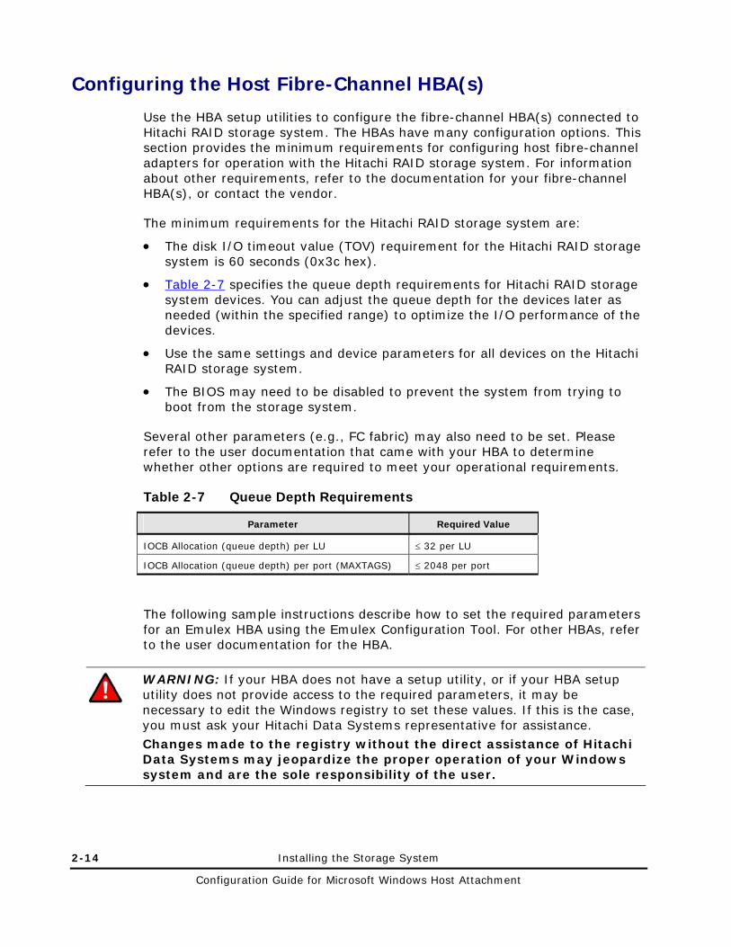
Configuring the Host Fibre-Channel HBA(s)
Use the HBA setup utilities to configure the fibre-channel HBA(s) connected to Hitachi RAID storage system. The HBAs have many configuration options. This section provides the minimum requirements for configuring host fibre-channel adapters for operation with the Hitachi RAID storage system. For information about other requirements, refer to the documentation for your fibre-channel HBA(s), or contact the vendor.
The minimum requirements for the Hitachi RAID storage system are:
• The disk I/O timeout value (TOV) requirement for the Hitachi RAID storage system is 60 seconds (0x3c hex).
• 1Table 2-7 specifies the queue depth requirements for Hitachi RAID storage system devices. You can adjust the queue depth for the devices later as needed (within the specified range) to optimize the I/O performance of the devices.
• Use the same settings and device parameters for all devices on the Hitachi RAID storage system.
• The BIOS may need to be disabled to prevent the system from trying to boot from the storage system.
Several other parameters (e.g., FC fabric) may also need to be set. Please refer to the user documentation that came with your HBA to determine whether other options are required to meet your operational requirements.
Table 2-7 Queue Depth Requirements
Parameter Required Value
IOCB Allocation (queue depth) per LU ≤ 32 per LU
IOCB Allocation (queue depth) per port (MAXTAGS) ≤ 2048 per port
The following sample instructions describe how to set the required parameters for an Emulex HBA using the Emulex Configuration Tool. For other HBAs, refer to the user documentation for the HBA.
WARNING: If your HBA does not have a setup utility, or if your HBA setup utility does not provide access to the required parameters, it may be necessary to edit the Windows registry to set these values. If this is the case, you must ask your Hitachi Data Systems representative for assistance. Changes made to the registry without the direct assistance of Hitachi Data Systems may jeopardize the proper operation of your Windows system and are the sole responsibility of the user.

Installing the Storage System 2-15
Configuration Guide for Microsoft Windows Host Attachment
To set the queue depth and other device parameters using the Emulex utility:
1. Set the queue depth (Maximum Queue Depth) using the Emulex Configuration Tool as shown in Figure 2-3.
2. For the SCSI Port Driver, set the value of Link Timer to 60 as shown in Figure 2-4. (The default value is 30.)
3. Verify all other required settings for your environment (e.g., support for more than eight LUNs per target ID). Refer to the HBA documentation as needed.
4. Save your changes, and exit the utility. If you need to change any settings, reboot the Windows system, and use the HBA setup utility again.
Figure 2-3 Setting the Queue Depth Using Emulex Configuration Tool
Figure 2-4 Setting the I/O TOV (Link Timer)

2-16 Installing the Storage System
Configuration Guide for Microsoft Windows Host Attachment
Verifying the Disk and Device Parameters
After you configure the fibre-channel ports and HBAs, verify the disk I/O timeout value, queue depth, and other required parameters such as FC fabric support.
Verifying the Disk I/O Timeout Value (TOV)
The disk I/O TOV parameter, which applies to all SCSI disk devices attached to the Windows system, must be set to 60 seconds. The default setting is hexadecimal 0x3c (decimal 60).
WARNING: The following procedure is intended for the system administrator with the assistance of the Hitachi Data Systems representative. Use the Registry Editor with extreme caution. Do not change the system registry without the direct assistance of Hitachi Data Systems. For information and instructions about the registry, refer to the online help for the Registry Editor.
To verify the disk I/O TOV using the Registry Editor:
1. Start the Windows Registry Editor: click Start, click Run, and enter regedt32 in the Run dialog box.
2. Go to HKEY_LOCAL_MACHINE SYSTEM CurrentControlSet Services Disk to display the disk parameters.
3. Verify that the TimeOutValue disk parameter is set to 60 seconds (0x3c), as shown in Figure 2-5.
4. Verify other required settings for your operational environment (e.g., FC fabric support). Refer to the HBA documentation as needed.
5. Exit the Registry Editor.
6. If you need to change any settings, reboot the Windows system, and use the HBA setup utility to change the settings. If you are not able to change the settings using the HBA utility, ask your Hitachi Data Systems representative for assistance.

Installing the Storage System 2-17
Configuration Guide for Microsoft Windows Host Attachment
Figure 2-5 Verifying the Disk I/O TOV Using the Registry Editor

2-18 Installing the Storage System
Configuration Guide for Microsoft Windows Host Attachment
Verifying the Queue Depth
The queue depth requirements for the devices are specified in 1Table 2-7 above. The following sample instructions describe how to verify the queue depth for a QLogic HBA using the Registry Editor.
WARNING: The following procedure is intended for the system administrator with the assistance of the Hitachi Data Systems representative. Use the Registry Editor with extreme caution. Do not change the system registry without the direct assistance of Hitachi Data Systems. For information and instructions about the registry, refer to the online help for the Registry Editor.
To verify the queue depth and other device parameters using the Registry Editor:
1. Start the Windows Registry Editor: click Start, click Run, and enter regedt32 in the Run dialog box.
2. Go to HKEY_LOCAL_MACHINE SYSTEM CurrentControlSet Services ql2200 (or ql2300) Parameters Device to display the device parameters for the QLogic fibre-channel HBA (see Figure 2-6).
3. Verify that the queue depth value in DriverParameter meets the requirements for the Hitachi RAID storage system (see 1Table 2-7 above).
4. If connected to a fabric switch, make sure FabricSupported=1 appears in DriverParameter.
5. Verify other required settings for your environment (e.g., FC fabric support, support for more than eight LUNs per target ID). Refer to the HBA documentation as needed.
6. Make sure the device parameters are the same for all devices on the Hitachi RAID storage system.
7. Exit the Registry Editor.
8. If you need to change any settings, reboot the Windows system, and use the HBA setup utility to change the settings. If you are not able to change the settings using the HBA utility, ask your Hitachi Data Systems representative for assistance.

Installing the Storage System 2-19
Configuration Guide for Microsoft Windows Host Attachment
Figure 2-6 Verifying the Queue Depth Using the Registry Editor

2-20 Installing the Storage System
Configuration Guide for Microsoft Windows Host Attachment

3
Configuring the New Disk Devices 3-1
Configuration Guide for Microsoft Windows Host Attachment
Configuring the New Disk Devices
This chapter describes how to configure the new disk devices. The topics in this chapter are:
Writing the Signatures
Creating and Formatting the Partitions
Verifying File System Operations
Verifying Auto-Mount
Changing the Enable Write Caching Option
Notes: • The logical devices on the Hitachi RAID storage system are defined to the
host as SCSI disk devices, even though the interface is fibre channel. • Do not create partitions on the FX devices. If the FX devices will be used in
the MSCS environment, you must write a signature on each FX device. If not, do not write a signature.
• For information about the FC AL-PA to SCSI TID mapping, see Appendix A: SCSI TID Maps for FC Adapters.
• Online LUSE expansion: data migration is not needed for OPEN-V (required for other LU types). A host reboot is not required for Windows. For more information, see your Hitachi Data Systems representative.

3-2 Configuring the New Disk Devices
Configuration Guide for Microsoft Windows Host Attachment
Writing the Signatures
The first step when configuring new devices is to write a signature on each device using the Windows Disk Management. You must write a signature on each SCSI disk device to enable the Windows system to vary the device online. For MSCS environments, you must also write signatures on the FX and other raw devices. The 32-bit signature identifies the disk to the Windows system. If the disk’s TID and/or LUN is changed, or if the disk is moved to a different controller, the Disk Management and Windows fault-tolerant driver will continue to recognize it.
Note: Microsoft Windows assigns disk numbers sequentially, starting with the local disks and then by adapter, and by TID/LUN. If the Hitachi RAID storage system is attached to the first adapter (displayed first during system start-up), the disk numbers for the new devices start at 1 (the local disk is 0). If the Hitachi RAID storage system is not attached to the first adapter, the disk numbers for the new devices start at the next available disk number. For example, if 40 disks are attached to the first adapter (disks 1–40) and the Hitachi RAID storage system is attached to the second adapter, the disk numbers for the Hitachi RAID storage system start at 41
To write the signatures on the new disk devices (see Figure 3-1):
1. Click the Start button, point to Programs, point to Administrative Tools (Computer Management), and click Disk Management to start the Disk Manager. Initialization takes a few seconds.
2. When the Disk Management notifies you that one or more disks have been added, click OK to allow the system configuration to be updated.
Note: If you removed any disks, the Disk Management will also notify you at this time.
3. The Disk Management displays each new device by disk number and asks if you want to write a signature on the disk (see 2Figure 3-2). You may only write a signature once on each device. Refer to your completed SCSI Path Worksheet (see 2Table 2-6) to verify the device type for each disk number.
– For all SCSI disk devices, click OK to write a signature.
– For FX devices without MSCS, click No.
– For FX devices with MSCS, click Yes and observe this warning:
WARNING: After a signature has been written on an FX device, there is no way to distinguish the FX device from a SCSI disk device. Use extreme caution to not accidentally partition and format an FX device. This will overwrite any data on the FX device and prevent the FX software from accessing the device.

Configuring the New Disk Devices 3-3
Configuration Guide for Microsoft Windows Host Attachment
4. After you write or decline to write a signature on each new device, the Disk Management window displays the devices by disk number (see Figure 3-1). The total capacity and free space is displayed for each disk device with a signature. Configuration information not available indicates no signature. For directions on creating partitions on the new SCSI disk devices, see Creating and Formatting the Partitions to create.
Figure 3-1 Disk Management Window Showing New Devices
Note: In the example in the figure above, disk 0 is the local disk, disk 1 is an OPEN-3 device, disk 2 is an OPEN-3 device, and disk 3 is an OPEN-3 device.

3-4 Configuring the New Disk Devices
Configuration Guide for Microsoft Windows Host Attachment
Figure 3-2 Writing the Signatures

Configuring the New Disk Devices 3-5
Configuration Guide for Microsoft Windows Host Attachment
Creating and Formatting the Partitions
After write signatures on the new devices, create and format the partitions on the new SCSI disk devices. Use your completed SCSI Device Worksheet (see 2Table 2-6) as needed to verify disk numbers and device types.
Dynamic Disk is supported with no restrictions for the Hitachi RAID storage system connected to the Windows operating system. For more information, refer to the Microsoft Windows online help.
Note: Do not partition or create a file system on a device which will be used as a raw device (e.g., some database applications use raw devices). All FX devices are raw devices.
To create and format partitions on the new SCSI disk devices:
1. On the Disk Management window, select the unallocated area for the SCSI disk you want to partition, click the Action menu, and then click Create Partition to launch the New Partition Wizard.
2. When the Select Partition Type dialog box appears (see Figure 3-3), select the desired type of partition and click Next.
Note: The Hitachi RAID storage systems do not support Stripe Set Volume with parity.
3. When the Specify Partition Size dialog box appears (see Figure 3-4), specify the desired partition size. If the size is greater than 1024 MB, you will be asked to confirm the new partition. Click Next.
4. When the Assign Drive Letter or Path dialog box appears (see Figure 3-5), select a drive letter or path, or specify no drive letter or drive path. Click Next.
5. When the Format Partition dialog box appears (see Figure 3-6), click Format this partition with the following settings and select the following options:
– File System: Select NTFS (enables the Windows system to write to the disk).
– Allocation unit size: Default. Do not change this entry.
– Volume label: Enter a volume label, or leave this field blank for no label.
– Format Options: Select Perform a Quick Format to decrease the time required to format the partition. Select Enable file and folder compression only if you want to enable compression.

3-6 Configuring the New Disk Devices
Configuration Guide for Microsoft Windows Host Attachment
6. Select Next to format the partition as specified. When the format warning appears (this new format will erase all existing data on disk), click OK to continue. The Format dialog box shows the progress of the format partition operation.
7. When the format operation is complete, click OK. The New Partition Wizard displays the new partition (see Figure 3-7). Click Finish to close the New Partition Wizard.
8. Verify that the Disk Management window shows the correct file system (NTFS) for the formatted partition (see 2Figure 3-8). The word Healthy indicates that the partition has been created and formatted successfully.
9. Repeat steps 1 through 8 for each new SCSI disk device. When you finish creating and formatting partitions, exit the Disk Management. When the disk configuration change message appears, click Yes to save your changes.
Note: Be sure to make your new Emergency Repair Disk using RDISK.EXE.
Figure 3-3 New Partition Wizard Dialog Box

Configuring the New Disk Devices 3-7
Configuration Guide for Microsoft Windows Host Attachment
Figure 3-4 Specifying the Partition Size
Figure 3-5 Assigning the Drive Letter or Path

3-8 Configuring the New Disk Devices
Configuration Guide for Microsoft Windows Host Attachment
Figure 3-6 Formatting the Partition
Figure 3-7 Successful Formatting Confirmation Dialog Box

Configuring the New Disk Devices 3-9
Configuration Guide for Microsoft Windows Host Attachment
Figure 3-8 Verifying the Formatted Partition

3-10 Configuring the New Disk Devices
Configuration Guide for Microsoft Windows Host Attachment
Verifying File System Operations
After you create and format the partitions, verify that the file system is operating properly on each new SCSI disk device. The file system enables the Windows host to access the devices. You can verify file system operation easily by copying a file onto each new device. If the file is copied successfully, this verifies that the file system is operating properly and that Windows can access the new device.
Note: Do not perform this procedure for FX and other raw devices. Instead, use the FX File Conversion Utility (FCU) or File Access Library (FAL) to access the FX devices.
To verify file system operations for the new SCSI disk devices:
1. From the Windows desktop, double-click My Computer to display all connected devices. All newly partitioned disks appear in this window (see 2Figure 3-9).
2. Select the device you want to verify, then display its Properties using either of the following methods:
– On the File menu, click Properties.
– Right-click and select Properties.
3. On the Properties dialog box (see 2Figure 3-10), verify that the following properties are correct:
– Label (optional)
– Type
– Capacity
– File system
4. Copy a small file to the new device.
5. Display the contents of the new device to be sure the copy operation completed successfully (see 2Figure 3-11). The copied file should appear with the correct file size. If desired, compare the copied file with the original file to verify no differences.
6. Delete the copied file from the new device, and verify the file was deleted successfully.
7. Repeat steps 2 through 6 for each new SCSI disk device.

Configuring the New Disk Devices 3-11
Configuration Guide for Microsoft Windows Host Attachment
Figure 3-9 Displaying the Connected Devices
Note: In the example above, (E:) and (F:) are the new devices.

3-12 Configuring the New Disk Devices
Configuration Guide for Microsoft Windows Host Attachment
Figure 3-10 Verifying the New Device Properties
Figure 3-11 Verifying the File Copy Operation

Configuring the New Disk Devices 3-13
Configuration Guide for Microsoft Windows Host Attachment
Verifying Auto-Mount
The last step in configuring the new devices is to verify that all new devices are mounted automatically at system boot-up.
To verify auto-mount of the new devices:
1. Shut down and then restart the Windows system.
2. Open My Computer and verify that all new SCSI disk devices are displayed.
3. Verify that the Windows host can access each new device by repeating the procedure in Verifying File System Operations:
a. Verify the device properties for each new device (see Figure 3-10).
b. Copy a file to each new device to be sure the devices are working properly (see Figure 3-11).

3-14 Configuring the New Disk Devices
Configuration Guide for Microsoft Windows Host Attachment
Changing the Enable Write Caching Option
The Enable Write Cache option has no effect on the cache algorithm when used with HDS storage systems and is not related to any internal Windows server caching. Microsoft and Hitachi Data Systems both recommend that you enable this option because it will provide a small improvement to Microsoft error reporting.
To enable or disable the setting Enable write caching on the disk:
1. Right-click My Computer.
2. Click Manage.
3. Click Device Manager.
4. Click the plus sign (+) next to Disk Drives. A list of all the disk drives appears.
5. Double-click the first HDS system disk drive.
6. Click the Policies or Disk Properties tab.
7. If Enable write caching on the disk is enabled, a check mark appears next to it. To disable this option, clear the check mark (see Figure 3-12).
If the Enable Write Cache option is grayed-out, this option is disabled.
8. Repeat this procedure for all additional HDS system disks.

Configuring the New Disk Devices 3-15
Configuration Guide for Microsoft Windows Host Attachment
Figure 3-12 Example of the Enable Write Caching on the Disk Option Being Disabled

3-16 Configuring the New Disk Devices
Configuration Guide for Microsoft Windows Host Attachment

4
Failover and SNMP Operations 4-1
Configuration Guide for Microsoft Windows Host Attachment
Failover and SNMP Operations
The Hitachi RAID storage systems support industry-standard products and functions that provide host and/or application failover, I/O path failover, and logical volume management (LVM). The Hitachi RAID storage systems also support the industry-standard simple network management protocol (SNMP) for remote system management from the UNIX/PC server host. SNMP is used to transport management information between the storage system and the SNMP manager on the host. The SNMP agent sends status information to the host(s) when requested by the host or when a significant event occurs.
This chapter describes how failover and SNMP operations are supported on the Hitachi RAID storage system.
Host Failover
Path Failover
Windows 2008 MPIO Configuration Procedure
SNMP Remote System Management
Note: The user is responsible for configuring the failover and SNMP management software on the UNIX/PC server host. For assistance with failover and/or SNMP configuration on the host, refer to the user documentation, or contact the vendor’s technical support.

4-2 Failover and SNMP Operations
Configuration Guide for Microsoft Windows Host Attachment
Host Failover
The Hitachi RAID storage systems support the MSCS host failover feature of the Windows operating system.
Note: To configure an MSCS environment via a fabric switch, use zoning functionality per each host bus adapter.
When Hitachi RAID storage system devices operate in an MSCS environment, write signatures on the devices (see Writing the Signatures). For MSCS operations, allow the Windows Disk Management to write a signature on all SCSI disk devices and all FX devices (e.g., 3390-3A/B/C, OPEN-3 for FXoto).
After device configuration is complete, configure the MSCS software to recognize the newly attached devices on the Hitachi RAID storage system.
For assistance with MSCS operations, refer to the Microsoft user documentation or contact Microsoft customer support.
Note about cluster shared volume: • When cluster shared volume (CSV) is used in the Hyper-V+MSFC
environment, each node always registers one unique PGR Key in each LU. The calculation method for the number of PGR keys is as follows: Number of PGR keys/port = (number of nodes) × (number of LUs) ≤ 128 128 = Reservation keys per port available for Hitachi RAID storage system
• In the case of shared LU other than CSV, one unique PGR Key is usually registered in each LU by the owner node. When failover occurs, for example due to node power loss, another PGR key is temporarily added in each LU (max 32 LUs concurrently). The number of PGR keys is calculated as follows: Number of PGR keys/port = (number of nodes) × (number of LUs) ≤ 128 CSV is available in Windows 2008 R2 or later.

Failover and SNMP Operations 4-3
Configuration Guide for Microsoft Windows Host Attachment
Path Failover
The Hitachi RAID storage systems support the Hitachi Dynamic Link Manager path failover and load balancing product for the Windows operating system. After you complete device configuration as described in Chapter 3: Configuring the New Disk Devices, configure the Hitachi Dynamic Link Manager as needed to recognize the newly attached devices on the Hitachi RAID storage system.
For assistance with Hitachi Dynamic Link Manager, refer to the Hitachi Dynamic Link Manager User’s Guide (MK-92DLM129) or contact your Hitachi Data Systems representative.

4-4 Failover and SNMP Operations
Configuration Guide for Microsoft Windows Host Attachment
Windows 2008 MPIO Configuration Procedure
Enabling MultiPath IO
The following procedure enables and configures the MultiPath IO (Input/Output) feature of the Windows Server Manager for HDS storage systems.
1. Launch Server Manager, and open the Administrator Tools menu.
2. Select Diagnostics, and then open Device Manager window (see Figure 4-1) and verify that HITACHI OPEN-x SCSI Disk Device is displayed as having n LDEV x 2 paths=2n devices.
Figure 4-1 Device Manager Window

Failover and SNMP Operations 4-5
Configuration Guide for Microsoft Windows Host Attachment
3. From Server Manager, select Features and click Add Features (see Figure 4-2.
Figure 4-2 Selecting the Add Features Window
4. In the Select Features window (see Figure 4-3) select “Multipath I/O” and Click “Next” If the Cluster option is selected, “Multipath I/O” and “Failover Clustering” must be selected.
Figure 4-3 Selecting MPIO Features

4-6 Failover and SNMP Operations
Configuration Guide for Microsoft Windows Host Attachment
5. Confirm the installed content (Mutlipath I/O) and Click Install to start the installation (see Figure 4-4).
Figure 4-4 Starting the Installation
6. When the Installation Results window appears (see Figure 4-5), review and confirm (if successful) by clicking Close.
Figure 4-5 Successful Installation Notice

Failover and SNMP Operations 4-7
Configuration Guide for Microsoft Windows Host Attachment
Note: If the system notice in Figure 4-6 appears, restart the server.
Figure 4-6 Restart Server Notice
7. To launch MPIO, select Start, then from the Control Panel (Figure 4-7, double-click the MPIO icon.
Figure 4-7 Launching the MPIO driver

4-8 Failover and SNMP Operations
Configuration Guide for Microsoft Windows Host Attachment
8. On the MPIO Properties window (see Figure 4-8), select the MPIO-ed Devices tab, select the device to add, and click Add.
Figure 4-8 MPIO Properties Tab Window
9. When the Add MPIO Support window (see Figure 4-9) opens, enter HITACHI OPEN-, and click OK.
Figure 4-9 Add MPIO Support Window

Failover and SNMP Operations 4-9
Configuration Guide for Microsoft Windows Host Attachment
10. When the Reboot Required message appears (see Figure 4-10), click Yes.
Figure 4-10 Reboot Required Window
11. After the reboot, go to Server Manager, select Diagnostics and in the Device Manager window (Figure 4-11) and verify that “HITACHI OPEN-x Multi-Path Disk Device” is displayed correctly.
Figure 4-11 Device Manager Window

4-10 Failover and SNMP Operations
Configuration Guide for Microsoft Windows Host Attachment
12. To set the Balance Policy, select the device and right-click to access its properties window (see Figure 4-12). Select Round Robin for each LU. This policy setting is selectable on a per device basis.
Figure 4-12 Setting Load Balance Policy
This completes enabling and configuring the MPIO feature.

Failover and SNMP Operations 4-11
Configuration Guide for Microsoft Windows Host Attachment
SNMP Remote System Management
SNMP is a part of the TCP/IP protocol suite that supports maintenance functions for storage and communication devices. The Hitachi RAID storage systems use SNMP to transfer status and management commands to the SNMP Manager on the UNIX/PC server host (see Figure 4-13). When the SNMP manager requests status information or when a service information message (SIM) occurs, the SNMP agent on the storage system notifies the SNMP manager on the UNIX/PC server. Notification of error conditions is made in real time, providing the UNIX/PC server user with the same level of monitoring and support available to the mainframe user. The SIM reporting via SNMP enables the user to monitor the Hitachi RAID storage system from the UNIX/PC server host.
When a SIM occurs, the SNMP agent on the Hitachi RAID storage system initiates trap operations, which alert the SNMP manager of the SIM condition. The SNMP manager receives the SIM traps from the SNMP agent, and can request information from the SNMP agent at any time.
Note: The user is responsible for configuring the SNMP manager on the Windows host. For assistance with SNMP manager configuration on the Windows host, refer to the user documentation, or contact the vendor’s technical support.
Private LAN
Error Info.Public LAN
SNMP Manager
Service Processor
UNIX/PC Server
SIM
Hitachi RAID storage system
Figure 4-13 SNMP Environment

4-12 Failover and SNMP Operations
Configuration Guide for Microsoft Windows Host Attachment

5
Troubleshooting 5-1
Configuration Guide for Microsoft Windows Host Attachment
Troubleshooting
This chapter provides troubleshooting information for Windows host attachment and includes instructions for calling technical support.
General Troubleshooting
Calling the Hitachi Data Systems Support Center

5-2 Troubleshooting
Configuration Guide for Microsoft Windows Host Attachment
General Troubleshooting
Table 5-1 lists potential error conditions that may occur during installation of new storage and provides instructions for resolving the conditions. If you cannot resolve an error condition, contact your Hitachi Data Systems representative, or call the Hitachi Data Systems Support Center for assistance (see Calling Hitachi Data Systems Support Center for instructions).
For troubleshooting information on the Hitachi RAID storage system, see the User and Reference Guide for the storage system (e.g., Hitachi Virtual Storage Platform User and Reference Guide).
For troubleshooting information on Hitachi Storage Navigator, see the Storage Navigator User’s Guide for the storage system (e.g., Hitachi Virtual Storage Platform Storage Navigator User’s Guide).
For information on errors messages displayed by Storage Navigator, see the Storage Navigator Messages document for the storage system (e.g., Hitachi Virtual Storage Platform Storage Navigator Messages).
Table 5-1 Troubleshooting
Error Condition Recommended Action
The devices are not recognized by the system.
Be sure the READY indicator lights on the storage system are ON.
Be sure the fibre cables are correctly installed and firmly connected.
The Windows system does not reboot properly after hard shutdown.
If the Windows system is powered off unexpectedly (without the normal shutdown process), wait three minutes before restarting the Windows system. This lets the storage system’s internal time-out process to purge all queued commands so the storage system is available (not busy) during system startup. If the Windows system is restarted too soon, the storage system tries to process the queued commands and the Windows system will not reboot successfully.

Troubleshooting 5-3
Configuration Guide for Microsoft Windows Host Attachment
Calling the Hitachi Data Systems Support Center
If you need to call the Hitachi Data Systems Support Center, please gather as much information about the problem as possible, including:
• The circumstances surrounding the error or failure.
• The content of any error message(s) displayed on the host system(s).
• The content of any error message(s) displayed on Storage Navigator.
• The service information messages (SIMs), including reference codes and severity levels, displayed by Storage Navigator.
The Hitachi Data Systems customer support staff is available 24 hours a day, seven days a week. If you need technical support, log on to the Hitachi Data Systems Portal for contact information: https://hdssupport.hds.com

5-4 Troubleshooting
Configuration Guide for Microsoft Windows Host Attachment

A
SCSI TID Maps for FC Adapters A-1
Configuration Guide for Microsoft Windows Host Attachment
SCSI TID Maps for FC Adapters
When an arbitrated loop (AL) is established or re-established, the port addresses are assigned automatically to prevent duplicate target IDs (TID). When using the SCSI over fibre-channel protocol (FCP), TIDs are no longer needed. SCSI is a bus-oriented protocol requiring each device to have a unique address since all commands go to all devices.
For fibre channel, the AL-PA is used instead of the TID to direct packets to the desired destination. Unlike traditional SCSI, once control of the loop is acquired, a point-to-point connection is established from the initiator to the target. To enable transparent use of FCP, the Windows operating system “maps” a TID to each AL-PA.
Tables A-1 and A-2 identify the fixed mappings between the bus/TID/LUN addresses assigned by Windows and the FC native addresses (AL_PA/SEL_ID) for fibre-channel HBAs. There are two potential mappings depending on the value of the ScanDown registry parameter:
• For ScanDown = 0 (default) see Table A-1.
• For ScanDown = 1 see Table A-2.
Note: When Hitachi RAID storage system devices and other types of devices are connected in the same arbitrated loop, the mappings defined in Tables A-1 and A-2 cannot be guaranteed.
Note: The Emulex driver emulates six SCSI buses per adapter to map all 126 possible AL-PAs to target IDs. The first bus (bus 0) is a dummy bus.
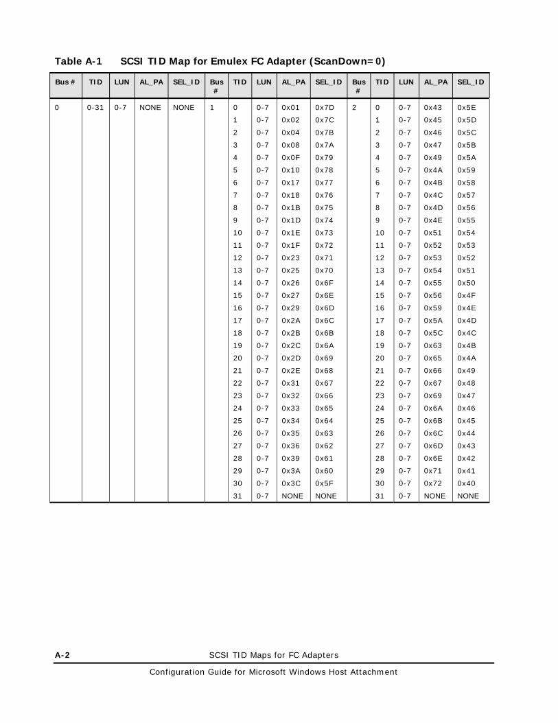
A-2 SCSI TID Maps for FC Adapters
Configuration Guide for Microsoft Windows Host Attachment
Table A-1 SCSI TID Map for Emulex FC Adapter (ScanDown=0)
Bus # TID LUN AL_PA SEL_ID Bus #
TID LUN AL_PA SEL_ID Bus #
TID LUN AL_PA SEL_ID
0 0-31 0-7 NONE NONE 1 0
1
2
3
4
5
6
7
8
9
10
11
12
13
14
15
16
17
18
19
20
21
22
23
24
25
26
27
28
29
30
31
0-7
0-7
0-7
0-7
0-7
0-7
0-7
0-7
0-7
0-7
0-7
0-7
0-7
0-7
0-7
0-7
0-7
0-7
0-7
0-7
0-7
0-7
0-7
0-7
0-7
0-7
0-7
0-7
0-7
0-7
0-7
0-7
0x01
0x02
0x04
0x08
0x0F
0x10
0x17
0x18
0x1B
0x1D
0x1E
0x1F
0x23
0x25
0x26
0x27
0x29
0x2A
0x2B
0x2C
0x2D
0x2E
0x31
0x32
0x33
0x34
0x35
0x36
0x39
0x3A
0x3C
NONE
0x7D
0x7C
0x7B
0x7A
0x79
0x78
0x77
0x76
0x75
0x74
0x73
0x72
0x71
0x70
0x6F
0x6E
0x6D
0x6C
0x6B
0x6A
0x69
0x68
0x67
0x66
0x65
0x64
0x63
0x62
0x61
0x60
0x5F
NONE
2 0
1
2
3
4
5
6
7
8
9
10
11
12
13
14
15
16
17
18
19
20
21
22
23
24
25
26
27
28
29
30
31
0-7
0-7
0-7
0-7
0-7
0-7
0-7
0-7
0-7
0-7
0-7
0-7
0-7
0-7
0-7
0-7
0-7
0-7
0-7
0-7
0-7
0-7
0-7
0-7
0-7
0-7
0-7
0-7
0-7
0-7
0-7
0-7
0x43
0x45
0x46
0x47
0x49
0x4A
0x4B
0x4C
0x4D
0x4E
0x51
0x52
0x53
0x54
0x55
0x56
0x59
0x5A
0x5C
0x63
0x65
0x66
0x67
0x69
0x6A
0x6B
0x6C
0x6D
0x6E
0x71
0x72
NONE
0x5E
0x5D
0x5C
0x5B
0x5A
0x59
0x58
0x57
0x56
0x55
0x54
0x53
0x52
0x51
0x50
0x4F
0x4E
0x4D
0x4C
0x4B
0x4A
0x49
0x48
0x47
0x46
0x45
0x44
0x43
0x42
0x41
0x40
NONE

SCSI TID Maps for FC Adapter A-3
Configuration Guide for Microsoft Windows Host Attachment
Table A-1 SCSI TID Map for Emulex FC Adapter (ScanDown=0) (continued)
Bus # TID LUN AL_PA SEL_ID Bus #
TID LUN AL_PA SEL_ID Bus #
TID LUN AL_PA SEL_ID
3 0
1
2
3
4
5
6
7
8
9
10
11
12
13
14
15
16
17
18
19
20
21
22
23
24
25
26
27
28
29
30
31
0-7
0-7
0-7
0-7
0-7
0-7
0-7
0-7
0-7
0-7
0-7
0-7
0-7
0-7
0-7
0-7
0-7
0-7
0-7
0-7
0-7
0-7
0-7
0-7
0-7
0-7
0-7
0-7
0-7
0-7
0-7
0-7
0x73
0x74
0x75
0x76
0x79
0x7A
0x7C
0x80
0x81
0x82
0x84
0x88
0x8F
0x90
0x97
0x98
0x9B
0x9D
0x9E
0x9F
0xA3
0xA5
0xA6
0xA7
0xA9
0xAA
0xAB
0xAC
0xAD
0xAE
0xB1
NONE
0x3F
0x3E
0x3D
0x3C
0x3B
0x3A
0x39
0x38
0x37
0x36
0x35
0x34
0x33
0x32
0x31
0x30
0x2F
0x2E
0x2D
0x2C
0x2B
0x2A
0x29
0x28
0x27
0x26
0x25
0x24
0x23
0x22
0x21
NONE
4 0
1
2
3
4
5
6
7
8
9
10
11
12
13
14
15
16
17
18
19
20
21
22
23
24
25
26
27
28
29
30
31
0-7
0-7
0-7
0-7
0-7
0-7
0-7
0-7
0-7
0-7
0-7
0-7
0-7
0-7
0-7
0-7
0-7
0-7
0-7
0-7
0-7
0-7
0-7
0-7
0-7
0-7
0-7
0-7
0-7
0-7
0-7
0-7
0xB2
0xB3
0xB4
0xB5
0xB6
0xB9
0xBA
0xBC
0xC3
0xC5
0xC6
0xC7
0xC9
0xCA
0xCB
0xCC
0xCD
0xCE
0xD1
0xD2
0xD3
0xD4
0xD5
0xD6
0xD9
0xDA
0xDC
0xE0
0xE1
0xE2
0xE4
NONE
0x20
0x1F
0x1E
0x1D
0x1C
0x1B
0x1A
0x19
0x18
0x17
0x16
0x15
0x14
0x13
0x12
0x11
0x10
0x0F
0x0E
0x0D
0x0C
0x0B
0x0A
0x09
0x08
0x07
0x06
0x05
0x04
0x03
0x02
NONE
5 0
1
2
3
4
5
6
7
8
9
10
11
12
13
14
15
16
17
18
19
20
21
22
23
24
25
26
27
28
29
30
31
0-7
0-7
0-7
0-7
0-7
0-7
0-7
0-7
0-7
0-7
0-7
0-7
0-7
0-7
0-7
0-7
0-7
0-7
0-7
0-7
0-7
0-7
0-7
0-7
0-7
0-7
0-7
0-7
0-7
0-7
0-7
0-7
0xE8
0xEF
NONE
NONE
NONE
NONE
NONE
NONE
NONE
NONE
NONE
NONE
NONE
NONE
NONE
NONE
NONE
NONE
NONE
NONE
NONE
NONE
NONE
NONE
NONE
NONE
NONE
NONE
NONE
NONE
NONE
NONE
0x01
0x00
NONE
NONE
NONE
NONE
NONE
NONE
NONE
NONE
NONE
NONE
NONE
NONE
NONE
NONE
NONE
NONE
NONE
NONE
NONE
NONE
NONE
NONE
NONE
NONE
NONE
NONE
NONE
NONE
NONE
NONE

A-4 SCSI TID Maps for FC Adapters
Configuration Guide for Microsoft Windows Host Attachment
Table A-2 SCSI TID Map for Emulex FC Adapter (ScanDown=1)
Bus # TID LUN AL_PA SEL_ID Bus #
TID LUN AL_PA SEL_ID Bus #
TID LUN AL_PA SEL_ID
0 0-31 0-7 NONE NONE 1 0
1
2
3
4
5
6
7
8
9
10
11
12
13
14
15
16
17
18
19
20
21
22
23
24
25
26
27
28
29
30
31
0-7
0-7
0-7
0-7
0-7
0-7
0-7
0-7
0-7
0-7
0-7
0-7
0-7
0-7
0-7
0-7
0-7
0-7
0-7
0-7
0-7
0-7
0-7
0-7
0-7
0-7
0-7
0-7
0-7
0-7
0-7
0-7
0xEF
0xE8
0xE4
0xE2
0xE1
0xE0
0xDC
0xDA
0xD9
0xD6
0xD5
0xD4
0xD3
0xD2
0xD1
0xCE
0xCD
0xCC
0xCB
0xCA
0xC9
0xC7
0xC6
0xC5
0xC3
0xBC
0xBA
0xB9
0xB6
0xB5
0xB4
NONE
0x00
0x01
0x02
0x03
0x04
0x05
0x06
0x07
0x08
0x09
0x0A
0x0B
0x0C
0x0D
0x0E
0x0F
0x10
0x11
0x12
0x13
0x14
0x15
0x16
0x17
0x18
0x19
0x1A
0x1B
0x1C
0x1D
0x1E
NONE
2 0
1
2
3
4
5
6
7
8
9
10
11
12
13
14
15
16
17
18
19
20
21
22
23
24
25
26
27
28
29
30
31
0-7
0-7
0-7
0-7
0-7
0-7
0-7
0-7
0-7
0-7
0-7
0-7
0-7
0-7
0-7
0-7
0-7
0-7
0-7
0-7
0-7
0-7
0-7
0-7
0-7
0-7
0-7
0-7
0-7
0-7
0-7
0-7
0xB3
0xB2
0xB1
0xAE
0xAD
0xAC
0xAB
0xAA
0xA9
0xA7
0xA6
0xA5
0xA3
0x9F
0x9E
0x9D
0x9B
0x98
0x97
0x90
0x8F
0x88
0x84
0x82
0x81
0x80
0x7C
0x7A
0x79
0x76
0x75
NONE
0x1F
0x20
0x21
0x22
0x23
0x24
0x25
0x26
0x27
0x28
0x29
0x2A
0x2B
0x2C
0x2D
0x2E
0x2F
0x30
0x31
0x32
0x33
0x34
0x35
0x36
0x37
0x38
0x39
0x3A
0x3B
0x3C
0x3D
NONE

SCSI TID Maps for FC Adapter A-5
Configuration Guide for Microsoft Windows Host Attachment
Table A-2 SCSI TID Map for Emulex FC Adapter (ScanDown=1) (continued)
Bus # TID LUN AL_PA SEL_ID Bus #
TID LUN AL_PA SEL_ID Bus #
TID LUN AL_PA SEL_ID
3 0
1
2
3
4
5
6
7
8
9
10
11
12
13
14
15
16
17
18
19
20
21
22
23
24
25
26
27
28
29
30
31
0-7
0-7
0-7
0-7
0-7
0-7
0-7
0-7
0-7
0-7
0-7
0-7
0-7
0-7
0-7
0-7
0-7
0-7
0-7
0-7
0-7
0-7
0-7
0-7
0-7
0-7
0-7
0-7
0-7
0-7
0-7
0-7
0x74
0x73
0x72
0x71
0x6E
0x6D
0x6C
0x6B
0x6A
0x69
0x67
0x66
0x65
0x63
0x5C
0x5A
0x59
0x56
0x55
0x54
0x53
0x52
0x51
0x4E
0x4D
0x4C
0x4B
0x4A
0x49
0x47
0x46
NONE
0x3E
0x3F
0x40
0x41
0x42
0x43
0x44
0x45
0x46
0x47
0x48
0x49
0x4A
0x4B
0x4C
0x4D
0x4E
0x4F
0x50
0x51
0x52
0x53
0x54
0x55
0x56
0x57
0x58
0x59
0x5A
0x5B
0x5C
NONE
4 0
1
2
3
4
5
6
7
8
9
10
11
12
13
14
15
16
17
18
19
20
21
22
23
24
25
26
27
28
29
30
31
0-7
0-7
0-7
0-7
0-7
0-7
0-7
0-7
0-7
0-7
0-7
0-7
0-7
0-7
0-7
0-7
0-7
0-7
0-7
0-7
0-7
0-7
0-7
0-7
0-7
0-7
0-7
0-7
0-7
0-7
0-7
0-7
0x45
0x43
0x3C
0x3A
0x39
0x36
0x35
0x34
0x33
0x32
0x31
0x2E
0x2D
0x2C
0x2B
0x2A
0x29
0x27
0x26
0x25
0x23
0x1F
0x1E
0x1D
0x1B
0x18
0x17
0x10
0x0F
0x08
0x04
NONE
0x5D
0x5E
0x5F
0x60
0x61
0x62
0x63
0x64
0x65
0x66
0x67
0x68
0x69
0x6A
0x6B
0x6C
0x6D
0x6E
0x6F
0x70
0x71
0x72
0x73
0x74
0x75
0x76
0x77
0x78
0x79
0x7A
0x7B
NONE
5 0
1
2
3
4
5
6
7
8
9
10
11
12
13
14
15
16
17
18
19
20
21
22
23
24
25
26
27
28
29
30
31
0-7
0-7
0-7
0-7
0-7
0-7
0-7
0-7
0-7
0-7
0-7
0-7
0-7
0-7
0-7
0-7
0-7
0-7
0-7
0-7
0-7
0-7
0-7
0-7
0-7
0-7
0-7
0-7
0-7
0-7
0-7
0-7
0x02
0x01
NONE
NONE
NONE
NONE
NONE
NONE
NONE
NONE
NONE
NONE
NONE
NONE
NONE
NONE
NONE
NONE
NONE
NONE
NONE
NONE
NONE
NONE
NONE
NONE
NONE
NONE
NONE
NONE
NONE
NONE
0x7C
0x7D
NONE
NONE
NONE
NONE
NONE
NONE
NONE
NONE
NONE
NONE
NONE
NONE
NONE
NONE
NONE
NONE
NONE
NONE
NONE
NONE
NONE
NONE
NONE
NONE
NONE
NONE
NONE
NONE
NONE
NONE

A-6 SCSI TID Maps for FC Adapters
Configuration Guide for Microsoft Windows Host Attachment

B
Creating an Online LUSE Volume B-1
Configuration Guide for Microsoft Windows Host Attachment
Creating an Online LUSE Volume
This appendix explains how to safely expand a LUSE volume in an online Windows operating system using Storage Navigator.
Note: It is recommended that you stop all I/O activity if possible before you perform an online LUSE expansion.
For the instructions below, the following applies:
LDEV # = 0:32
Mount point = i
capacity = 40 MB
Complete the following steps:
1. Right click My Computer, and then select Manage.
2. From the pull down menu, select Disk Management to confirm that Disk I is mounted and that Disk 12 is on this system.
Disk 12 is the disk that will be expanded.

B-2 Creating an Online LUSE Volume
Configuration Guide for Microsoft Windows Host Attachment
Figure B-1 Selecting the Manage Command

Creating an Online LUSE Volume B-3
Configuration Guide for Microsoft Windows Host Attachment
3. Right click on the disk number and select Properties to obtain more detailed information.
In this example, detailed information for Disk 13 is displayed.
Figure B-2 Viewing Disk Properties

B-4 Creating an Online LUSE Volume
Configuration Guide for Microsoft Windows Host Attachment
4. Start Storage Navigator.
Figure B-3 Storage Navigator Screen
5. From the vertical menu bar on the left side of the window, select the LUN Expansion icon:
6. In the LDEV Information pane on the left side of the window, open a CU
folder and select an LDEV.
7. Enable Write privileges by clicking the pen icon in the top-right corner:
8. Using the Select an LDEV drop-down list, select an LDEV. The free LDEVs
appear in the Free LDEVs area at the bottom right of the page and the LDEV you selected appears in the Expanded LDEVs list.

Creating an Online LUSE Volume B-5
Configuration Guide for Microsoft Windows Host Attachment
Figure B-4 Adding LDEVs
9. In the Free LDEVs area, click an LDEV and click the Add button to move the selected LDEV to the Expanded LDEVs list. Repeat this step for each additional LDEV you want to add.
Note: To select multiple LDEVs that are next to each other, click the first LDEV you want to add; then hold down the Shift key and select the last LDEV. All the LDEVs between the first and last ones you selected are selected. If the LDEVs are not adjacent, select the first LDEV you want to add; then hold down the Ctrl key and select each additional LDEV you want to add.
10. Click the Set button. The following message appears:
11. Click the OK button to continue.

B-6 Creating an Online LUSE Volume
Configuration Guide for Microsoft Windows Host Attachment
12. Click the Apply button. The following message appears:
13. Click the OK button to apply. The following message appears:
14. Click the OK button to remove the message.
You have just created the online LUSE.

Creating an Online LUSE Volume B-7
Configuration Guide for Microsoft Windows Host Attachment
The next step is to use DISKPART to configure Windows host to recognize the expanded LDEV.
1. Return to the Windows Computer Management application.
2. Select Action from the Menu bar, then select Rescan from the Action subfunctions to refresh the display.
After this is done, you will see that the mounted volume I:\ (disk 12) is expanded from 40 MB to 80 MB. At this point, however, the newly added disk is not yet formatted. You now must use Diskpart to combine the new partition.
Figure B-5 Example of a Mounted Volume that has been Expanded
Note: Before using Diskpart, please read all applicable instructions.
3. From a command prompt, enter Diskpart and press Enter.
4. At the DISKPART> prompt enter list disk and press Enter. A list of disks appears.
5. When you have identified the disk to be expanded (Disk 1 in this example), enter select disk=1 (for this example) and press Enter. Disk 1 is now the selected disk on which the operations will be performed.

B-8 Creating an Online LUSE Volume
Configuration Guide for Microsoft Windows Host Attachment
Figure B-6 Selecting a Disk to be Expanded
a. At the DISKPART> prompt enter detail disk and press Enter. Disk details will be shown.
b. Select the volume to be used. For this example, enter select volume = 4 and press Enter.
Figure B-7 Selecting a Volume

Creating an Online LUSE Volume B-9
Configuration Guide for Microsoft Windows Host Attachment
c. At the DISKPART> prompt, enter extend and press Enter to combine the available volumes for the selected disk into a single partition.
d. Enter detail disk at the DISKPART> prompt and press Enter to verify that the size is 68G.

B-10 Creating an Online LUSE Volume
Configuration Guide for Microsoft Windows Host Attachment

Acronyms and Abbreviations Acronyms-1
Configuration Guide for Microsoft Windows Host Attachment
Acronyms and Abbreviations
AL arbitrated loop AL-PA arbitrated loop physical address
blk block
CVS custom volume size
FAL File Access Library FC fibre-channel FCP fibre-channel protocol FCU file conversion utility FX Hitachi Cross-OS File Exchange
GB gigabyte Gbps gigabits per second
HBA host bus adapter HDLM Hitachi Dynamic Link Manager
I/O input/output
KB kilobyte
LU logical unit LUN logical unit number LUSE LUN Expansion LVI logical volume image LVM Logical Volume Manager
MB megabyte MPE maximum number of physical extents MSCS Microsoft Cluster Server
OFC open fibre control
PA physical address PC personal computer PP physical partition
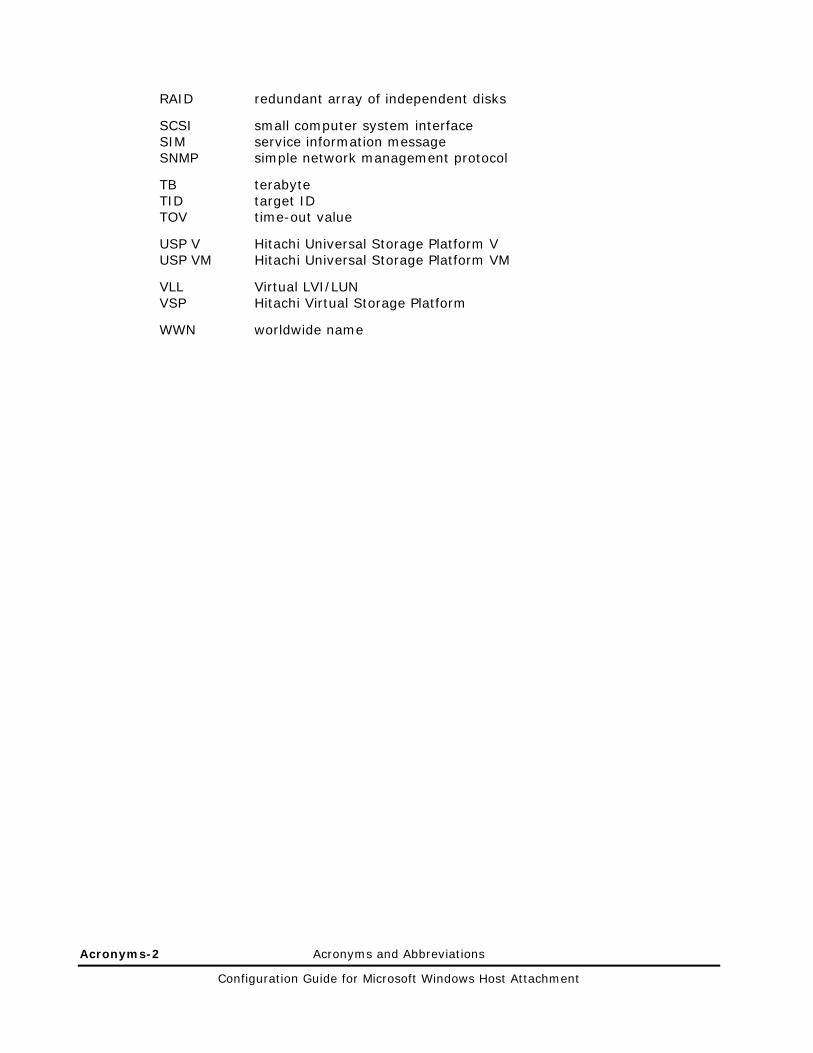
Acronyms-2 Acronyms and Abbreviations
Configuration Guide for Microsoft Windows Host Attachment
RAID redundant array of independent disks
SCSI small computer system interface SIM service information message SNMP simple network management protocol
TB terabyte TID target ID TOV time-out value
USP V Hitachi Universal Storage Platform V USP VM Hitachi Universal Storage Platform VM
VLL Virtual LVI/LUN VSP Hitachi Virtual Storage Platform
WWN worldwide name

Configuration Guide for Microsoft Windows Host Attachment

MK-96RD639-06
Hitachi Data Systems
Corporate Headquarters 750 Central Expressway Santa Clara, California 95050-2627 U.S.A. Phone: 1 408 970 1000 www.hds.com [email protected]
Asia Pacific and Americas 750 Central Expressway Santa Clara, California 95050-2627 U.S.A. Phone: 1 408 970 1000 [email protected]
Europe Headquarters Sefton Park Stoke Poges Buckinghamshire SL2 4HD United Kingdom Phone: + 44 (0)1753 618000 [email protected]