configurable embedded cpg based control for robot locomotion
12
International Journal of Advanced Robotic Systems Configurable Embedded CPG-based Control for Robot Locomotion Regular Paper Jose Hugo Barron-Zambrano 1,* , Cesar Torres-Huitzil 1 and Bernard Girau 2 1 Cinvestav-Tamaulipas, Information Technology Laboratory, Victoria, Mexico 2 Loria, University Nancy 1, Vandoeuvre-les-Nancy, France * Corresponding author E-mail: [email protected] Received 30 Apr 2012; Accepted 21 Jun 2012 DOI: 10.5772/50985 © 2012 Barron-Zambrano et al.; licensee InTech. This is an open access article distributed under the terms of the Creative Commons Attribution License (http://creativecommons.org/licenses/by/3.0), which permits unrestricted use, distribution, and reproduction in any medium, provided the original work is properly cited. Abstract Recently, the development of intelligent robots has benefited from a deeper understanding of the biomechanics and neurology of biological systems. Researchers have proposed the concept of Central Pattern Generators (CPGs) as a mechanism for generating an efficient control strategy for legged robots based on biological locomotion principles. Although many studies have aimed to develop robust legged locomotion controllers, relatively few of them have focused on adopting the technology for fully practical embedded hardware implementations. In this contribution, a reconfigurable hardware implementation of a CPG‐based controller which is able to generate several gaits for quadruped and hexapod robots is presented. The proposed implementation is modular and configurable in order to scale up to legged robots with different degrees of freedom. Experimental results for embedded Field Programmable Gate Array (FPGA) implementations for quadruped and hexapod robot controllers are presented and analysed. Keywords Central pattern generators, legged robot, FPGA, locomotion control. 1. Introduction The technological progress and the synergy of fields such as biology, neuroscience, artificial intelligence and robotics, among many others, have made possible the current levels of progress in the development of autonomous robots. A deeper understanding of the biomechanics and neurology of biological systems has further motivated the use of biologically inspired methods for the design and control of robots in order to avoid hand coding or in‐depth a priori knowledge so as to deal with every aspect of an autonomous robot’s environment [1]. Locomotion in legged robots is much more complex than with wheeled robots, since the former has between twelve or twenty degrees of freedom, which must be rhythmically coordinated to produce specific gaits. In nature, neural architectures and mechanisms ‐ referred to as Central Pattern Generators ‐ are responsible for controlling rhythmic functions in animals. It has been shown, by means of neurophysiological studies, that many activities vital to animal locomotion, such as walking, swimming and flying, are produced by the repetitive and rhythmic activations of animal muscles. 1 ARTICLE www.intechopen.com Int J Adv Robotic Sy, 2012, Vol. 9, 92:2012
description
Â
Transcript of configurable embedded cpg based control for robot locomotion
International Journal of Advanced Robotic Systems Configurable Embedded CPG-based Control for Robot Locomotion Regular Paper
Jose Hugo Barron-Zambrano1,*, Cesar Torres-Huitzil1 and Bernard Girau2 1 Cinvestav-Tamaulipas, Information Technology Laboratory, Victoria, Mexico 2 Loria, University Nancy 1, Vandoeuvre-les-Nancy, France * Corresponding author E-mail: [email protected] Received 30 Apr 2012; Accepted 21 Jun 2012 DOI: 10.5772/50985 © 2012 Barron-Zambrano et al.; licensee InTech. This is an open access article distributed under the terms of the Creative Commons Attribution License (http://creativecommons.org/licenses/by/3.0), which permits unrestricted use, distribution, and reproduction in any medium, provided the original work is properly cited.
Abstract Recently, the development of intelligent robots has benefited from a deeper understanding of the biomechanics and neurology of biological systems. Researchers have proposed the concept of Central Pattern Generators (CPGs) as a mechanism for generating an efficient control strategy for legged robots based on biological locomotion principles. Although many studies have aimed to develop robust legged locomotion controllers, relatively few of them have focused on adopting the technology for fully practical embedded hardware implementations. In this contribution, a reconfigurable hardware implementation of a CPG‐based controller which is able to generate several gaits for quadruped and hexapod robots is presented. The proposed implementation is modular and configurable in order to scale up to legged robots with different degrees of freedom. Experimental results for embedded Field Programmable Gate Array (FPGA) implementations for quadruped and hexapod robot controllers are presented and analysed. Keywords Central pattern generators, legged robot, FPGA, locomotion control.
1. Introduction The technological progress and the synergy of fields such as biology, neuroscience, artificial intelligence and robotics, among many others, have made possible the current levels of progress in the development of autonomous robots. A deeper understanding of the biomechanics and neurology of biological systems has further motivated the use of biologically inspired methods for the design and control of robots in order to avoid hand coding or in‐depth a priori knowledge so as to deal with every aspect of an autonomous robot’s environment [1]. Locomotion in legged robots is much more complex than with wheeled robots, since the former has between twelve or twenty degrees of freedom, which must be rhythmically coordinated to produce specific gaits. In nature, neural architectures and mechanisms ‐ referred to as Central Pattern Generators ‐ are responsible for controlling rhythmic functions in animals. It has been shown, by means of neurophysiological studies, that many activities vital to animal locomotion, such as walking, swimming and flying, are produced by the repetitive and rhythmic activations of animal muscles.
1Jose Hugo Barron-Zambrano, Cesar Torres-Huitzil and Bernard Girau: Configurable Embedded CPG-based Control for Robot Locomotion
www.intechopen.com
ARTICLE
www.intechopen.com Int J Adv Robotic Sy, 2012, Vol. 9, 92:2012
Researchers have studied CPGs for decades and some principles have been derived in order to model their functionality and structure. CPGs consist of sets of neural oscillators that receive inputs from command neurons. These oscillators produce rhythmic patterns of neural activity that activate motor neurons [2]. Though sustained rhythmic outputs can be produced by a CPG without need for sensory feedback, the feedback mechanism plays an important role in regulating the frequency and phase of oscillators to change locomotion patterns depending on the situation and the environment. Furthermore, CPGs induce some of the coordination among the several physical parts of animals so as to produce smooth locomotion patterns. From an engineering point of view, robust CPG‐based legged locomotion controllers have been developed using dedicated hardware, both analogue and digital [7‐9,20]. Two examples of these works are presented in [10] and [2]. In the first, Inagaki et al. present a method to control gait generation and its speed for an autonomous decentralized multi‐legged hexapod robot using CPGs. The topological structure of the CPG is represented as a graph on which two time evolution systems ‐ the Hamilton system and a gradient system ‐ are introduced. The oscillator model used in this work was the wave CPG model. The robot locomotion control is composed of subsystems formed by a motor and a microcomputer. The subsystems are connected mechanically and communicate with neighbours. Each microcomputer computes the dynamics of two oscillators and sends and receives the data computed by itself and by its neighbours. Gait generation and its speed control are achieved by controlling the virtual energy of the oscillators (Hamiltonian). The CPG is able to generate three different gaits and the transition among them. In the second, Nakada et al. present a neuromorphic analogue CMOS (Complementary Metal Oxide Semiconductor) controller for inter‐limb coordination in quadruped locomotion. In this paper, the authors used the Amari‐Hopfield neuron model as the neural oscillator. The model consists of an excitatory neuron and an inhibitory neuron with excitatory/inhibitory connections. The CPG is capable of producing various rhythmic patterns and changing these patterns promptly, but it cannot be used in other robot morphologies. Both works present control schemes based on biological systems and they are capable of adapting to different pattern gaits. Similar features are seen in animal locomotion tasks. These implementations were done with digital and analogue technology and both approaches present advantages and disadvantages. CPGs implemented using microprocessors provide high computational accuracy and flexibility in terms of modification or configuration, but they consume a lot of power and occupy a large area which restricts their utility
when in embedded robot applications [2]. On the other hand, the use of analogue circuits offers similar behaviour to biological neurons and the efficient management of energy, but they usually lack the flexibility to be reconfigured, modified or scaled‐up to different robots. They involve large design cycles for each modification and sometimes it is necessary to redesign the whole module. In spite of its importance, relatively few works have focused on adopting the CPG approach for fully practical embedded implementations. In this contribution, we propose embedded implementations of adaptive CPG‐based locomotion systems for legged robots. The implementation will be able to generate different gaits and will be configurable for robots with different degrees freedom. The CPG implementation based on FPGA technology provides a real‐time response, the flexibility to be modified or reconfigured but low power consumption and concurrent processing solutions for low‐level locomotion issues [11]. Also, FPGA implementations occupy a small area and present a shorter design time compared with analogue design. Furthermore, FPGAs have been shown to be suitable for neural processing, i.e., processing where massively distributed elementary units interact through dense interconnection schemes. The rest of the paper is organized as follows. Section 2 presents the biological foundations of animal locomotion and the neural oscillator to model the CPGs. Section 3 provides the details of various design considerations and a strategy for an embedded implementation of the CPGs targeted at FPGAs for different robot morphologies. Considerations on CPG parameter tuning using evolutionary computation are described in section 4. In section 5, experimental results and a discussion on both the embedded implementation and gait generation are presented. Finally, the conclusion and future work is presented in section 6. 2. Biological principles of animal locomotion and modelling. Despite the great diversity found in the structure of the locomotor organs and the central nervous system of different species, it has been established that their locomotor control is based on a few common fundamental principles. The activity of the locomotor organs (e.g., legs, wings, etc.) generates a propulsive force that leads to locomotion. Each piece of a locomotor organ is rhythmically controlled by a special neural network that generates the rhythm pattern. These low‐level neural networks, controlling each individual organ, interact with others so as to coordinate, in a distributed manner, the locomotor action of a complete species. Moreover, they also adopt their activity to the surrounding environment through sensory feedback and higher‐level signals from the central nervous system [2,3].
2 Int J Adv Robotic Sy, 2012, Vol. 9, 92:2012 www.intechopen.com
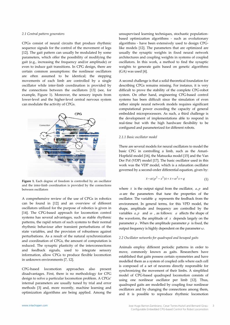
2.1 Central pattern generators CPGs consist of neural circuits that produce rhythmic sequence signals for the control of the movement of legs [12]. The gait pattern can usually be modulated by some parameters, which offer the possibility of modifying the gait (e.g., increasing the frequency and/or amplitude) or even to induce gait transitions. In CPG design, there are certain common assumptions: the nonlinear oscillators are often assumed to be identical; the stepping movements of each limb are controlled by a single oscillator while inter‐limb coordination is provided by the connections between the oscillators [13] (see, for example, Figure 1). Moreover, the sensory inputs from lower‐level and the higher‐level central nervous system can modulate the activity of CPGs.
Figure 1. Each degree of freedom is controlled by an oscillator and the inter‐limb coordination is provided by the connections between oscillators A comprehensive review of the use of CPGs in robotics can be found in [12] and an overview of different oscillators utilized for the purpose of robotics is given in [14]. The CPG‐based approach for locomotion control systems has several advantages, such as stable rhythmic patterns, the rapid return of such systems to their normal rhythmic behaviour after transient perturbations of the state variables, and the provision of robustness against perturbations. As a result of the natural synchronization and coordination of CPGs, the amount of computation is reduced. The synaptic plasticity of the interconnections and feedback signals, used to integrate sensory information, allow CPGs to produce flexible locomotion in unknown environments [7, 12]. CPG‐based locomotion approaches also present disadvantages. First, there is no methodology for CPG design to solve a particular locomotion problem. A CPGs’ internal parameters are usually tuned by trial and error methods [3] and, more recently, machine learning and optimization algorithms are being applied. Among the
unsupervised learning techniques, stochastic population‐based optimization algorithms ‐ such as evolutionary algorithms ‐ have been extensively used to design CPG‐like models [12]. The parameters that are optimized are usually the synaptic weights in fixed neural network architectures and coupling weights in systems of coupled oscillators. In this work, a method to find the synaptic weights to generate gaits based on genetic algorithms (GA) was used [4]. A second challenge is that a solid theoretical foundation for describing CPGs remains missing. For instance, it is very difficult to prove the stability of the complete CPG‐robot system. On other hand, engineering CPG‐based control systems has been difficult since the simulation of even rather simple neural network models requires significant computational power exceeding the capacity of general embedded microprocessors. As such, a third challenge is the development of implementations able to respond in real‐time but with the high hardware flexibility to be configured and parameterized for different robots.
2.1.1 Basic oscillator model There are several models for neural oscillators to model the basic CPG in controlling a limb, such as the Amari‐Hopfield model [16], the Matsuoka model [15] and the Van Der Pol (VDP) model [17]. The basic oscillator used in this work was the VDP model, which is a relaxation oscillator governed by a second‐order differential equation, given by:
(1) where x is the output signal from the oscillator, pa, and are the parameters that tune the properties of the oscillator. The variable q represents the feedback from the environment. In general terms, for this VPD model, the shape, amplitude and frequency are controlled by the variables pa, and , as follows: a affects the shape of the waveform, the amplitude of x depends largely on the parameter p . When the amplitude parameter p is xed, the output frequency is highly dependent on the parameter ω. 2.2 Oscillator networks for quadruped and hexapod gaits Animals employ different periodic patterns in order to move, commonly known as gaits. Researchers have established that gaits possess certain symmetries and have modelled them as a system of coupled cells where each cell is composed of a set of neurons directly responsible for synchronizing the movement of their limbs. A simplified model of CPG‐based quadruped locomotion consists of using one nonlinear oscillator per limb [12]. Thus, quadruped gaits are modelled by coupling four nonlinear oscillators and by changing the connections among them, and it is possible to reproduce rhythmic locomotion
qxxxxpx 222 )(
3Jose Hugo Barron-Zambrano, Cesar Torres-Huitzil and Bernard Girau: Configurable Embedded CPG-based Control for Robot Locomotion
www.intechopen.com
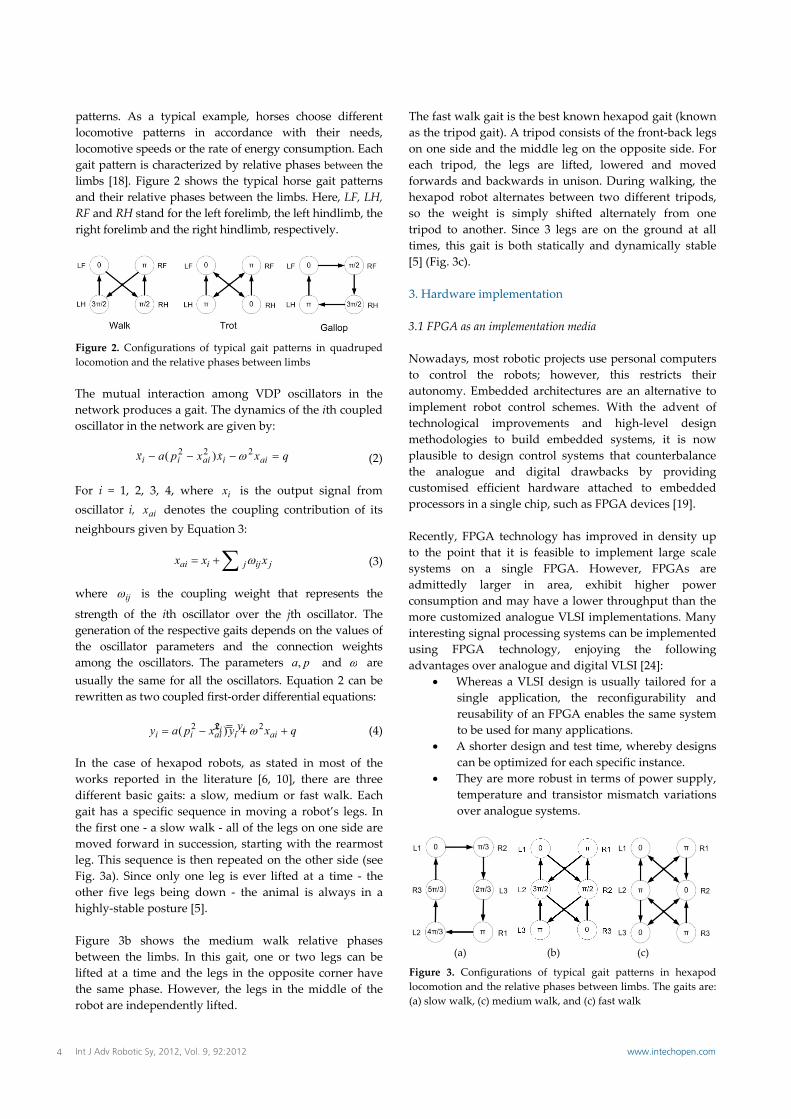
patterns. As a typical example, horses choose different locomotive patterns in accordance with their needs, locomotive speeds or the rate of energy consumption. Each gait pattern is characterized by relative phases between the limbs [18]. Figure 2 shows the typical horse gait patterns and their relative phases between the limbs. Here, LF, LH, RF and RH stand for the left forelimb, the left hindlimb, the right forelimb and the right hindlimb, respectively.
Figure 2. Configurations of typical gait patterns in quadruped locomotion and the relative phases between limbs The mutual interaction among VDP oscillators in the network produces a gait. The dynamics of the ith coupled oscillator in the network are given by:
(2) For i = 1, 2, 3, 4, where ix is the output signal from oscillator i, aix denotes the coupling contribution of its neighbours given by Equation 3:
(3) where ij is the coupling weight that represents the
strength of the ith oscillator over the jth oscillator. The generation of the respective gaits depends on the values of the oscillator parameters and the connection weights among the oscillators. The parameters pa, and are usually the same for all the oscillators. Equation 2 can be rewritten as two coupled first‐order differential equations:
(4)
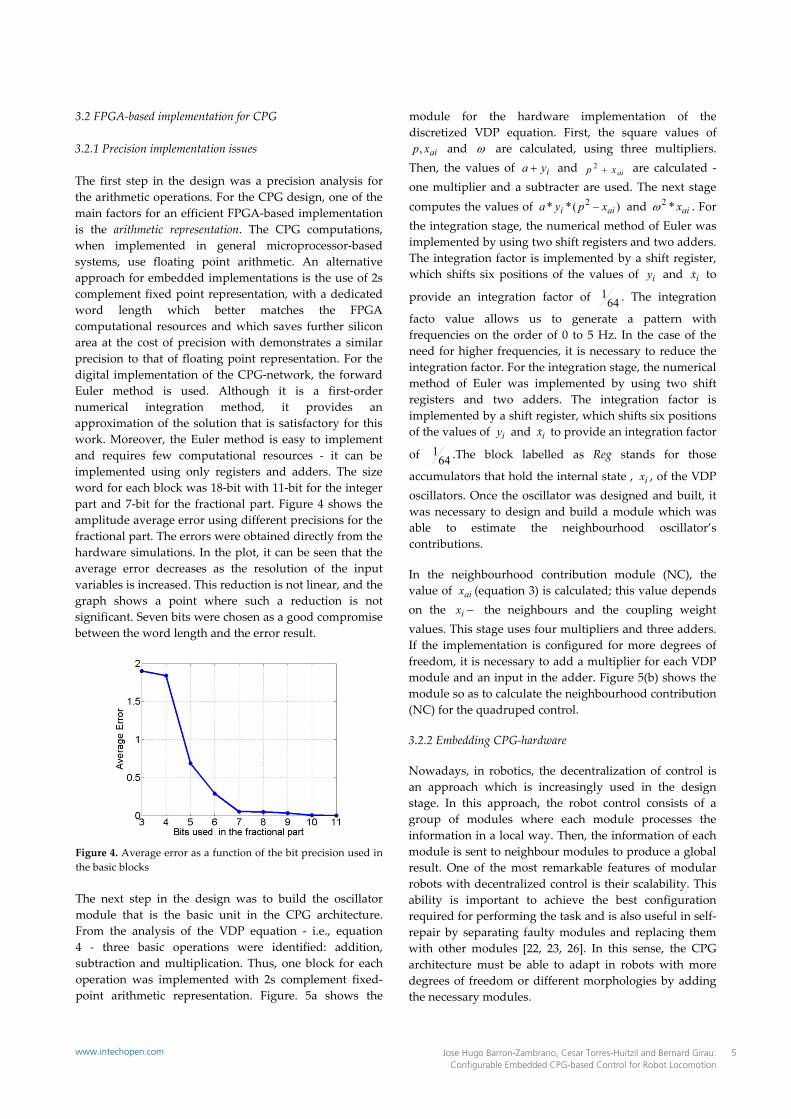
In the case of hexapod robots, as stated in most of the works reported in the literature [6, 10], there are three different basic gaits: a slow, medium or fast walk. Each gait has a specific sequence in moving a robot’s legs. In the first one ‐ a slow walk ‐ all of the legs on one side are moved forward in succession, starting with the rearmost leg. This sequence is then repeated on the other side (see Fig. 3a). Since only one leg is ever lifted at a time ‐ the other five legs being down ‐ the animal is always in a highly‐stable posture [5]. Figure 3b shows the medium walk relative phases between the limbs. In this gait, one or two legs can be lifted at a time and the legs in the opposite corner have the same phase. However, the legs in the middle of the robot are independently lifted.
The fast walk gait is the best known hexapod gait (known as the tripod gait). A tripod consists of the front‐back legs on one side and the middle leg on the opposite side. For each tripod, the legs are lifted, lowered and moved forwards and backwards in unison. During walking, the hexapod robot alternates between two different tripods, so the weight is simply shifted alternately from one tripod to another. Since 3 legs are on the ground at all times, this gait is both statically and dynamically stable [5] (Fig. 3c). 3. Hardware implementation 3.1 FPGA as an implementation media Nowadays, most robotic projects use personal computers to control the robots; however, this restricts their autonomy. Embedded architectures are an alternative to implement robot control schemes. With the advent of technological improvements and high‐level design methodologies to build embedded systems, it is now plausible to design control systems that counterbalance the analogue and digital drawbacks by providing customised efficient hardware attached to embedded processors in a single chip, such as FPGA devices [19]. Recently, FPGA technology has improved in density up to the point that it is feasible to implement large scale systems on a single FPGA. However, FPGAs are admittedly larger in area, exhibit higher power consumption and may have a lower throughput than the more customized analogue VLSI implementations. Many interesting signal processing systems can be implemented using FPGA technology, enjoying the following advantages over analogue and digital VLSI [24]:
Whereas a VLSI design is usually tailored for a single application, the reconfigurability and reusability of an FPGA enables the same system to be used for many applications.
A shorter design and test time, whereby designs can be optimized for each specific instance.
They are more robust in terms of power supply, temperature and transistor mismatch variations over analogue systems.
(a) (b) (c)
Figure 3. Configurations of typical gait patterns in hexapod locomotion and the relative phases between limbs. The gaits are: (a) slow walk, (c) medium walk, and (c) fast walk
qxxxpax aiiaiii 222 )(
jijjiai xxx
qxyxpay aiiaiii 222 )( ii yx
4 Int J Adv Robotic Sy, 2012, Vol. 9, 92:2012 www.intechopen.com
3.2 FPGA‐based implementation for CPG 3.2.1 Precision implementation issues The first step in the design was a precision analysis for the arithmetic operations. For the CPG design, one of the main factors for an efficient FPGA‐based implementation is the arithmetic representation. The CPG computations, when implemented in general microprocessor‐based systems, use floating point arithmetic. An alternative approach for embedded implementations is the use of 2s complement fixed point representation, with a dedicated word length which better matches the FPGA computational resources and which saves further silicon area at the cost of precision with demonstrates a similar precision to that of floating point representation. For the digital implementation of the CPG‐network, the forward Euler method is used. Although it is a first‐order numerical integration method, it provides an approximation of the solution that is satisfactory for this work. Moreover, the Euler method is easy to implement and requires few computational resources ‐ it can be implemented using only registers and adders. The size word for each block was 18‐bit with 11‐bit for the integer part and 7‐bit for the fractional part. Figure 4 shows the amplitude average error using different precisions for the fractional part. The errors were obtained directly from the hardware simulations. In the plot, it can be seen that the average error decreases as the resolution of the input variables is increased. This reduction is not linear, and the graph shows a point where such a reduction is not significant. Seven bits were chosen as a good compromise between the word length and the error result.
Figure 4. Average error as a function of the bit precision used in the basic blocks The next step in the design was to build the oscillator module that is the basic unit in the CPG architecture. From the analysis of the VDP equation ‐ i.e., equation 4 ‐ three basic operations were identified: addition, subtraction and multiplication. Thus, one block for each operation was implemented with 2s complement fixed‐point arithmetic representation. Figure. 5a shows the
module for the hardware implementation of the discretized VDP equation. First, the square values of
aixp, and are calculated, using three multipliers. Then, the values of iya and aixp 2 are calculated ‐ one multiplier and a subtracter are used. The next stage computes the values of )(** 2
aii xpya and aix*2 . For
the integration stage, the numerical method of Euler was implemented by using two shift registers and two adders. The integration factor is implemented by a shift register, which shifts six positions of the values of iy and ix to
provide an integration factor of 641 . The integration
facto value allows us to generate a pattern with frequencies on the order of 0 to 5 Hz. In the case of the need for higher frequencies, it is necessary to reduce the integration factor. For the integration stage, the numerical method of Euler was implemented by using two shift registers and two adders. The integration factor is implemented by a shift register, which shifts six positions of the values of iy and ix to provide an integration factor
of 641 .The block labelled as Reg stands for those
accumulators that hold the internal state , ix , of the VDP oscillators. Once the oscillator was designed and built, it was necessary to design and build a module which was able to estimate the neighbourhood oscillator’s contributions. In the neighbourhood contribution module (NC), the value of aix (equation 3) is calculated; this value depends on the ix the neighbours and the coupling weight values. This stage uses four multipliers and three adders. If the implementation is configured for more degrees of freedom, it is necessary to add a multiplier for each VDP module and an input in the adder. Figure 5(b) shows the module so as to calculate the neighbourhood contribution (NC) for the quadruped control. 3.2.2 Embedding CPG‐hardware Nowadays, in robotics, the decentralization of control is an approach which is increasingly used in the design stage. In this approach, the robot control consists of a group of modules where each module processes the information in a local way. Then, the information of each module is sent to neighbour modules to produce a global result. One of the most remarkable features of modular robots with decentralized control is their scalability. This ability is important to achieve the best configuration required for performing the task and is also useful in self‐repair by separating faulty modules and replacing them with other modules [22, 23, 26]. In this sense, the CPG architecture must be able to adapt in robots with more degrees of freedom or different morphologies by adding the necessary modules.
5Jose Hugo Barron-Zambrano, Cesar Torres-Huitzil and Bernard Girau: Configurable Embedded CPG-based Control for Robot Locomotion
www.intechopen.com

(a)
(b)
Figure 5. (a) Digital hardware architecture for the Van Der Pol oscillator. (b) Neighbourhood contribution module In the context of hardware architecture, the configurability can be defined as the ability to change the architecture functionality without a complete re‐design, using additional hardware, in order to meet a user need. In other words, CPG architecture must be able to generate different gaits using the same modules.
Figure 6. Final control scheme for legged locomotion based on the CPG and the environmental information. The modules in the dotted line are in the design and implementation stage To overcome the partial lack of flexibility and the configurability of CPG architecture, it has been attached as a specialized coprocessor to a microblaze processor.
The microblaze allows the setting of the values of the parameters in the hardware implementation through C‐based application. This application will receive information about other modules ‐ such as a vision module or sensors ‐ to configure the CPG (see Figure 6). The vision module might provide feedback from the environment through the detection of some patters in the scene. The sensor integration module allows us to process local information from the robot in the case where some limb presents problems during the gait. Furthermore, in the control scheme, there is the possibility of adding specialized modules for a specific robot and plugging them through the microblaze processor and C code. This advantage allows us to present a generic platform which is able to control different robots. To connect the processor and the CPG module, a parameterizable register bank is used to receive the input parameters,
ijpa ,,, and the initial values of each oscillator.
In Figure 7, several VDP modules are implemented and organized as an array of 2‐by‐2 elements so as to generate walk, trot and gallop gaits for quadruped robots. The first example of CPG‐hardware configurability is the ability to generate three different gaits by changing the connection values among the VDP modules.
Figure 7. CPG architecture for quadruped locomotion An example of CPG‐hardware scalability is the locomotion controller for a hexapod robot. In this example control, two VDP modules were added and organized as an array of 2‐by‐3 elements. In the case of a hexapod, as stated in most of the studies reported in the literature [7, 8], there are three different gait patterns: a slow, medium or a fast walk. As such, CPG control able to generate these three different hexapod gaits was designed and tested. The networks were obtained by choosing the connections between six VDP modules.
6 Int J Adv Robotic Sy, 2012, Vol. 9, 92:2012 www.intechopen.com
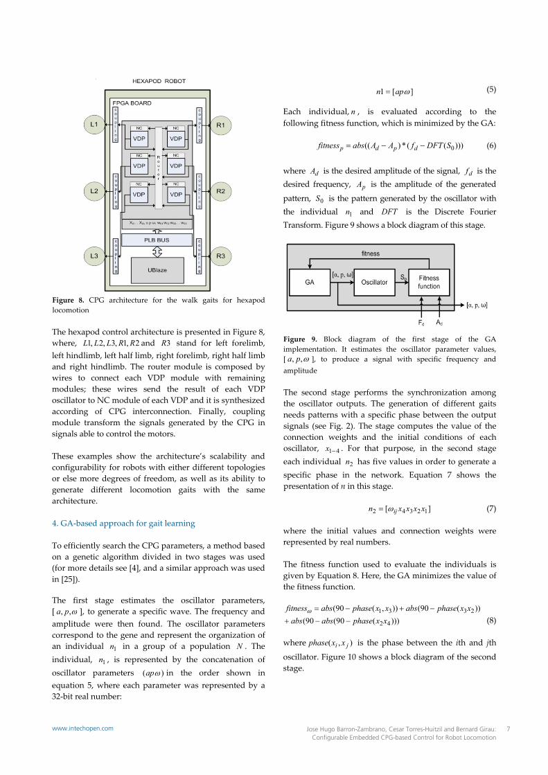
Figure 8. CPG architecture for the walk gaits for hexapod locomotion The hexapod control architecture is presented in Figure 8, where, 2,1,3,2,1 RRLLL and 3R stand for left forelimb, left hindlimb, left half limb, right forelimb, right half limb and right hindlimb. The router module is composed by wires to connect each VDP module with remaining modules; these wires send the result of each VDP oscillator to NC module of each VDP and it is synthesized according of CPG interconnection. Finally, coupling module transform the signals generated by the CPG in signals able to control the motors. These examples show the architecture’s scalability and configurability for robots with either different topologies or else more degrees of freedom, as well as its ability to generate different locomotion gaits with the same architecture. 4. GA‐based approach for gait learning To efficiently search the CPG parameters, a method based on a genetic algorithm divided in two stages was used (for more details see [4], and a similar approach was used in [25]). The first stage estimates the oscillator parameters, [ ,, pa ], to generate a specific wave. The frequency and amplitude were then found. The oscillator parameters correspond to the gene and represent the organization of an individual 1n in a group of a population N . The individual, 1n , is represented by the concatenation of oscillator parameters )( ap in the order shown in equation 5, where each parameter was represented by a 32‐bit real number:
(5)
Each individual, n , is evaluated according to the following fitness function, which is minimized by the GA:
)))((*)(( 0SDFTfAAabsfitness dpdp (6)
where dA is the desired amplitude of the signal, df is the desired frequency, pA is the amplitude of the generated
pattern, 0S is the pattern generated by the oscillator with the individual 1n and DFT is the Discrete Fourier Transform. Figure 9 shows a block diagram of this stage.
Figure 9. Block diagram of the first stage of the GA implementation. It estimates the oscillator parameter values, [ ,, pa ], to produce a signal with specific frequency and amplitude The second stage performs the synchronization among the oscillator outputs. The generation of different gaits needs patterns with a specific phase between the output signals (see Fig. 2). The stage computes the value of the connection weights and the initial conditions of each oscillator, 41x . For that purpose, in the second stage each individual 2n has five values in order to generate a specific phase in the network. Equation 7 shows the presentation of n in this stage.
(7) where the initial values and connection weights were represented by real numbers. The fitness function used to evaluate the individuals is given by Equation 8. Here, the GA minimizes the value of the fitness function.
(8) where ),( ji xxphase is the phase between the ith and jth
oscillator. Figure 10 shows a block diagram of the second stage.
][ 12342 xxxxn ij
][1 apn
)))(90(90())(90()),(90(
42
2331xxphaseabsabs
xxphaseabsxxphaseabsfitness
7Jose Hugo Barron-Zambrano, Cesar Torres-Huitzil and Bernard Girau: Configurable Embedded CPG-based Control for Robot Locomotion
www.intechopen.com
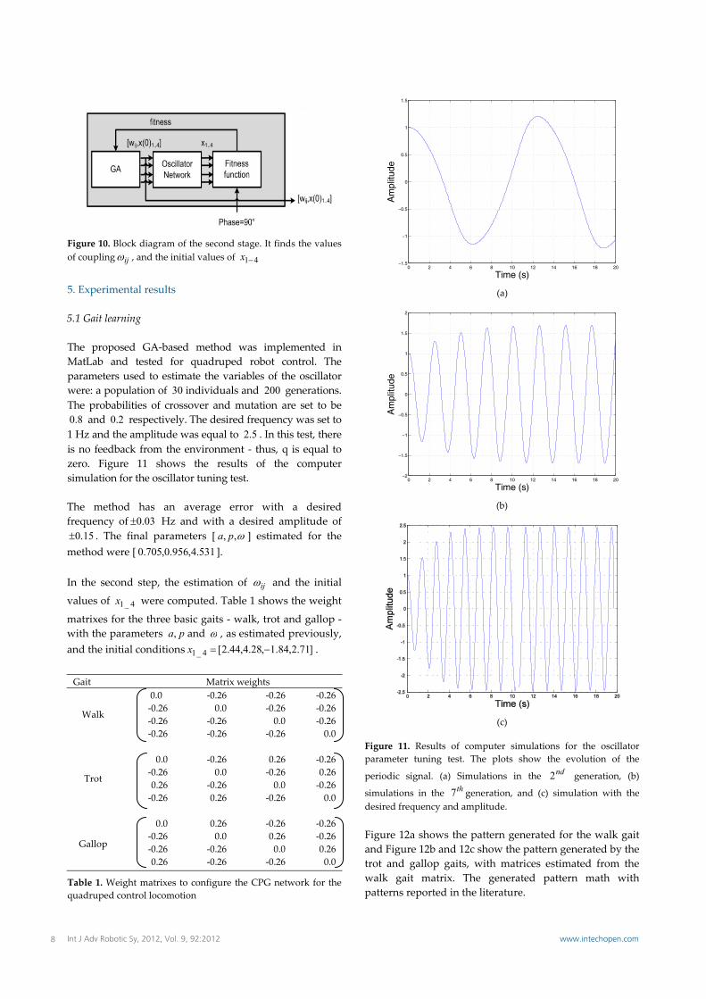
Figure 10. Block diagram of the second stage. It finds the values of coupling ij , and the initial values of 41x
5. Experimental results 5.1 Gait learning The proposed GA‐based method was implemented in MatLab and tested for quadruped robot control. The parameters used to estimate the variables of the oscillator were: a population of 30 individuals and 200 generations. The probabilities of crossover and mutation are set to be 8.0 and 2.0 respectively. The desired frequency was set to
1 Hz and the amplitude was equal to 5.2 . In this test, there is no feedback from the environment ‐ thus, q is equal to zero. Figure 11 shows the results of the computer simulation for the oscillator tuning test. The method has an average error with a desired frequency of 03.0 Hz and with a desired amplitude of
15.0 . The final parameters [ ,, pa ] estimated for the method were [ 531.4,956.0,705.0 ]. In the second step, the estimation of ij and the initial
values of 4_1x were computed. Table 1 shows the weight
matrixes for the three basic gaits ‐ walk, trot and gallop ‐ with the parameters pa, and , as estimated previously, and the initial conditions ]71.2,84.1,28.4,44.2[4_1 x .
Gait Matrix weights
Walk
0.0 ‐0.26 ‐0.26 ‐0.26 ‐0.26 0.0 ‐0.26 ‐0.26 ‐0.26 ‐0.26 0.0 ‐0.26 ‐0.26 ‐0.26 ‐0.26 0.0
Trot
0.0 ‐0.26 0.26 ‐0.26 ‐0.26 0.0 ‐0.26 0.26 0.26 ‐0.26 0.0 ‐0.26 ‐0.26 0.26 ‐0.26 0.0
Gallop
0.0 0.26 ‐0.26 ‐0.26 ‐0.26 0.0 0.26 ‐0.26 ‐0.26 ‐0.26 0.0 0.26 0.26 ‐0.26 ‐0.26 0.0
Table 1. Weight matrixes to configure the CPG network for the quadruped control locomotion
0 2 4 6 8 10 12 14 16 18 20−1.5
−1
−0.5
0
0.5
1
1.5
Time (s)
Am
plitu
de
(a)
0 2 4 6 8 10 12 14 16 18 20−2
−1.5
−1
−0.5
0
0.5
1
1.5
2
Time (s)
Am
plitu
de
(b)
(c)
Figure 11. Results of computer simulations for the oscillator parameter tuning test. The plots show the evolution of the
periodic signal. (a) Simulations in the nd2 generation, (b)
simulations in the th7 generation, and (c) simulation with the desired frequency and amplitude. Figure 12a shows the pattern generated for the walk gait and Figure 12b and 12c show the pattern generated by the trot and gallop gaits, with matrices estimated from the walk gait matrix. The generated pattern math with patterns reported in the literature.
8 Int J Adv Robotic Sy, 2012, Vol. 9, 92:2012 www.intechopen.com
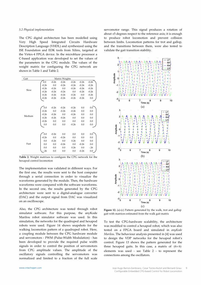
5.2 Physical implementation The CPG digital architecture has been modelled using Very High Speed Integrated Circuits Hardware Description Language (VHDL) and synthesized using the ISE Foundation and EDK tools from Xilinx, targeted at the Virtex‐4 FPGA device. In the microblaze processor a C‐based application was developed to set the values of the parameters in the CPG module. The values of the weight matrix for configuring the CPG network are shown in Table 1 and Table 2.
Gait Matrix Weights
Slow
0.0 ‐0.26 ‐0.26 ‐0.26 ‐0.26 ‐0.26 ‐0.26 0.0 ‐0.26 ‐0.26 ‐0.26 ‐0.26 ‐0.26 ‐0.26 0.0 ‐0.26 ‐0.26 ‐0.26 ‐0.26 ‐0.26 ‐0.26 0.0 ‐0.26 ‐0.26 ‐0.26 ‐0.26 ‐0.26 ‐0.26 ‐0.0 ‐0.26 ‐0.26 ‐0.26 ‐0.26 ‐0.26 ‐0.26 0.0
Medium
0.0 ‐0.26 ‐0.26 ‐0.26 0.0 0.0 ‐0.26 0.0 ‐0.26 ‐0.26 0.0 0.0 ‐0.26 ‐0.26 0.0 ‐0.26 0.0 0.0 ‐0.26 ‐0.26 ‐0.26 0.0 0.0 0.0 ‐0.26 0.0 0.0 0.0 0.0 0.0 0.0 0.0 0.0 ‐0.26 0.0 0.0
Fast
0.0 ‐0.26 0.0 0.0 0.0 0.0 ‐0.26 0.0 ‐0.26 0.0 0.0 0.0 0.0 ‐0.26 0.0 0.26 0.0 0.0 0.0 0.0 ‐0.26 0.0 ‐0.26 0.0 0.0 0.0 0.0 0.26 0.0 ‐.26 ‐‐.26 0.0 0.0 0.0 ‐0.26 0.0
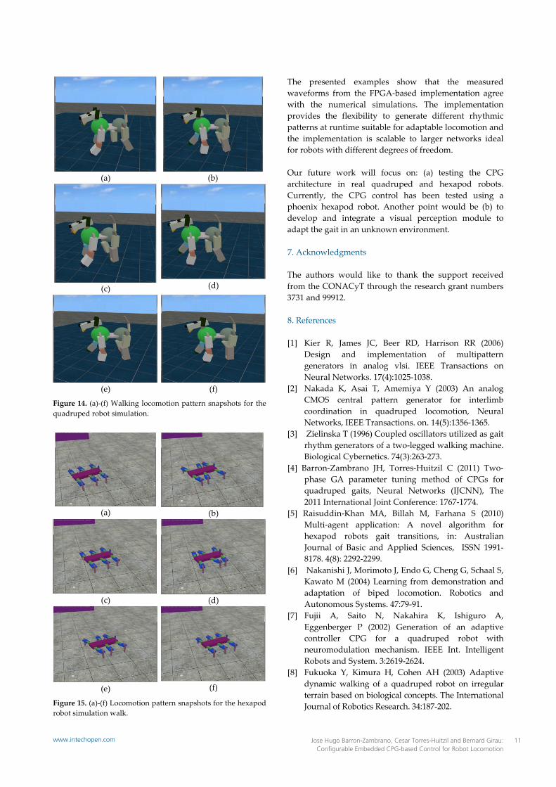
Table 2. Weight matrixes to configure the CPG network for the hexapod control locomotion The implementation was validated in different ways. For the first one, the results were sent to the host computer through a serial connection in order to visualize the waveforms generated by the module. Then, the hardware waveforms were compared with the software waveforms. In the second one, the results generated by the CPG architecture were sent to a digital‐analogue converter (DAC) and the output signal from DAC was visualized on an oscilloscope. Also, the CPG architecture was tested through robot simulator software. For this purpose, the anyKode Marilou robot simulator software was used. In this simulation, the networks for the quadruped and hexapod robots were used. Figure 14 shows snapshots for the walking locomotion pattern of a quadruped robot. Here, a coupling module between the CPG hardware module and servomotors ‐ PWM (Pulse‐Width Modulation) ‐ has been developed to provide the required pulse width signals in order to control the position of servomotors from CPG amplitude values. The amplitude of the oscillatory signals controlling the servomotors was normalized and limited to a fraction of the full scale
servomotor range. This signal produces a rotation of about ±5 degrees respect to the reference axis; it is enough to produce robot locomotion and prevent collision between limbs. Locomotion patterns for trot and gallop, and the transitions between them, were also tested to validate the gait transition stability.
(a)
(b)
(c)
Figure 12. (a)‐(c) Pattern generated by the walk, trot and gallop gait with matrices estimated from the walk gait matrix To test the CPG‐hardware scalability, the architecture was modified to control a hexapod robot, which was also tested on a FPGA board and simulated in anyKode Marilou. The behaviour analysis presented in [4] was used to design the VDP networks for the hexapod robot’s control. Figure 13 shows the pattern generated for the three hexapod gaits. In this case, a matrix of )66( elements was used ‐ see Table 2 ‐ to represent the connections among the oscillators.
9Jose Hugo Barron-Zambrano, Cesar Torres-Huitzil and Bernard Girau: Configurable Embedded CPG-based Control for Robot Locomotion
www.intechopen.com
Robot LUTs Flip‐Flops
Slices Embedded multipliers
% FPGA LUTs
CLK (MHz)
Quad Hexa
320 480
160 240
320 480
112 162
1 1
22 22
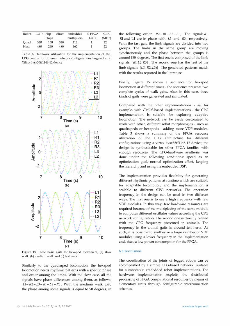
Table 3. Hardware utilization for the implementation of the CPG control for different network configurations targeted at a Xilinx 4vsx55ff1148‐12 device
(a)
(b)
(c)
Figure 13. Three basic gaits for hexapod movement, (a) slow walk, (b) medium walk and (c) fast walk. Similarly to the quadruped locomotion, the hexapod locomotion needs rhythmic patterns with a specific phase and order among the limbs. With the slow case, all the signals have phase differences among them, as follows:
321321 RLRLRL . With the medium walk gait, the phase among some signals is equal to 90 degrees, in
the following order: 1212 LLRR ,. The signals 1R 1R and L1 are in phase with 3L and 3R , respectively.
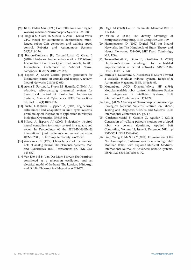
With the fast gait, the limb signals are divided into two groups. The limbs in the same group are moving synchronously and the phase between the groups is around180 degrees. The first one is composed of the limb signals ]3,2,1[ RLR . The second one has the rest of the limb signals )]3,2,1[( LRL . The generated patterns match with the results reported in the literature. Finally, Figure 15 shows a sequence for hexapod locomotion at different times ‐ the sequence presents two complete cycles of walk gaits. Also, in this case, three kinds of gaits were generated and simulated. Compared with the other implementations ‐ as, for example, with CMOS‐based implementations ‐ the CPG implementation is suitable for exploring adaptive locomotion. The network can be easily customized to work with other, different robot morphologies ‐ such as quadrupeds or hexapods ‐ adding more VDP modules. Table 3 shows a summary of the FPGA resource utilization of the CPG architecture for different configurations using a virtex 4vsx55ff1148‐12 device; the design is synthesizable for other FPGA families with enough resources. The CPG‐hardware synthesis was done under the following conditions: speed as an optimization goal, normal optimization effort, keeping the hierarchy and using the embedded DSP. The implementation provides flexibility for generating different rhythmic patterns at runtime which are suitable for adaptable locomotion, and the implementation is scalable to different CPG networks. The operation frequency in the design can be used in two different ways. The first one is to use a high frequency with few VDP modules. In this way, few hardware resources are required because of the multiplexing of the same module to computes different oscillator values according the CPG network configuration. The second one is directly related with the CPG frequency presented in animals. The frequency in the animal gaits is around ten hertz. As such, it is possible to synthesize a large number of VDP modules using a lower frequency in the implementation and, thus, a low power consumption for the FPGA. 6. Conclusions The coordination of the joints of legged robots can be accomplished by a simple CPG‐based network suitable for autonomous embedded robot implementations. The hardware implementation exploits the distributed processing of FPGA computational resources by means of elementary units through configurable interconnection schemes.
10 Int J Adv Robotic Sy, 2012, Vol. 9, 92:2012 www.intechopen.com
(a)
(b)
(c) (d)
(e) (f)
Figure 14. (a)‐(f) Walking locomotion pattern snapshots for the quadruped robot simulation.
(a) (b)
(c) (d)
(e) (f)
Figure 15. (a)‐(f) Locomotion pattern snapshots for the hexapod robot simulation walk.
The presented examples show that the measured waveforms from the FPGA‐based implementation agree with the numerical simulations. The implementation provides the flexibility to generate different rhythmic patterns at runtime suitable for adaptable locomotion and the implementation is scalable to larger networks ideal for robots with different degrees of freedom. Our future work will focus on: (a) testing the CPG architecture in real quadruped and hexapod robots. Currently, the CPG control has been tested using a phoenix hexapod robot. Another point would be (b) to develop and integrate a visual perception module to adapt the gait in an unknown environment. 7. Acknowledgments The authors would like to thank the support received from the CONACyT through the research grant numbers 3731 and 99912. 8. References [1] Kier R, James JC, Beer RD, Harrison RR (2006)
Design and implementation of multipattern generators in analog vlsi. IEEE Transactions on Neural Networks. 17(4):1025‐1038.
[2] Nakada K, Asai T, Amemiya Y (2003) An analog CMOS central pattern generator for interlimb coordination in quadruped locomotion, Neural Networks, IEEE Transactions. on. 14(5):1356‐1365.
[3] Zielinska T (1996) Coupled oscillators utilized as gait rhythm generators of a two‐legged walking machine. Biological Cybernetics. 74(3):263‐273.
[4] Barron‐Zambrano JH, Torres‐Huitzil C (2011) Two‐ phase GA parameter tuning method of CPGs for quadruped gaits, Neural Networks (IJCNN), The 2011 International Joint Conference: 1767‐1774.
[5] Raisuddin‐Khan MA, Billah M, Farhana S (2010) Multi‐agent application: A novel algorithm for hexapod robots gait transitions, in: Australian Journal of Basic and Applied Sciences, ISSN 1991‐8178. 4(8): 2292‐2299.
[6] Nakanishi J, Morimoto J, Endo G, Cheng G, Schaal S, Kawato M (2004) Learning from demonstration and adaptation of biped locomotion. Robotics and Autonomous Systems. 47:79‐91.
[7] Fujii A, Saito N, Nakahira K, Ishiguro A, Eggenberger P (2002) Generation of an adaptive controller CPG for a quadruped robot with neuromodulation mechanism. IEEE Int. Intelligent Robots and System. 3:2619‐2624.
[8] Fukuoka Y, Kimura H, Cohen AH (2003) Adaptive dynamic walking of a quadruped robot on irregular terrain based on biological concepts. The International Journal of Robotics Research. 34:187‐202.
11Jose Hugo Barron-Zambrano, Cesar Torres-Huitzil and Bernard Girau: Configurable Embedded CPG-based Control for Robot Locomotion
www.intechopen.com
[9] Still S, Tilden MW (1998) Controller for a four legged walking machine. Neuromorphic Systems: 138‐148.
[10] Inagaki S, Yuasa H, Suzuki T, Arai T (2006) Wave CPG model for autonomous decentralized multi‐legged robot: Gait generation and walking speed control, Robotics and Autonomous Systems. 54(2):118‐126.
[11] Barron‐Zambrano JH, Torres‐Huitzil C, Girau B (2010) Hardware Implementation of a CPG‐Based Locomotion Control for Quadruped Robots, In 20th International Conference on Artificial Neural Networks ‐ ICANN 2010, 276‐285.
[12] Ijspeert AJ (2002) Central pattern generators for locomotion control in animals and robots: A review. Neural Networks 21(4):642‐653.
[13] Arena P, Fortuna L, Frasca M, Sicurella G (2004) An adaptive, self‐organizing dynamical system for hierarchical control of bio‐inspired locomotion. Systems, Man and Cybernetics, IEEE Transactions on, Part B. 34(4):1823‐1837.
[14] Buchli J, Righetti L, Ijspeert AJ (2006) Engineering entrainment and adaptation in limit cycle systems. From biological inspiration to application in robotics, Biological Cybernetics. 95:645‐664.
[15] Billard A, Ijspeert AJ (2000) Biologically inspired neural controllers for motor control in a quadruped robot. In Proceedings of the IEEE‐INNS‐ENNS international joint conference on neural networks IJCNN 2000, IEEE Computer Society. 4:637‐641.
[16] Amarimber S (1972) Characteristic of the random nets of analog neuron‐like elements. Systems, Man and Cybernetics, IEEE Transactions on. SMC‐2(5): 643‐657.
[17] Van Der Pol B, Van Der Mark J (1928) The heartbeat considered as a relaxation oscillation, and an electrical model of the heart. The London, Edinburgh and Dublin Philosophical Magazine. 6:763‐775.
[18] Dagg AI (1973) Gait in mammals. Mammal Rev. 3: 135‐154.
[19] DeHon A (2000) The density advantage of configurable computing. IEEE Computer. 33:41‐49.
[20] Hammerstrom D (2002) Digital VLSI for Neural Networks. In: The Handbook of Brain Theory and Neural Networks, 304‐‐309, MIT Press. Cambridge, MA, USA.
[21] Torres‐Huitzil C, Girau B, Gauffriau A (2007) Hardware/software co‐design for embedded implementation of neural networks. ARCS 2007. LNCS. 4419:167‐178.
[22] Murata S, Kakomura K, Kurokawa H (2007) Toward a scalable modular robotic system. Robotics\& Automation Magazine, IEEE. 14(4):56‐63.
[23] Mutambara AGO, Durrant‐Whyte HF (1994) Modular scalable robot control. Multisensor Fusion and Integration for Intelligent Systems, IEEE International Conference on. 121‐127.
[24] Liu J, (2009) A Survey of Neuromorphic Engineering‐‐Biological Nervous Systems Realized on Silicon, Testing and Diagnosis, Circuits and Systems, IEEE International Conference on, pp. 1‐4.
[25] Cardenas‐Maciel S, Castillo O, Aguilar L (2011) Generation of walking periodic motions for a biped robot via genetic algorithms, Applied Soft Computing, Volume 11, Issue 8, December 2011, pp 5306‐5314, ISSN 1568‐4946.
[26] Liu J, Wang Y, Ma S, Li Y (2011). Enumeration of the Non‐Isomorphic Configurations for a Reconfigurable Modular Robot with Square‐Cubic‐Cell Modules, International Journal of Advanced Robotic Systems, ISSN: 1729‐8806, InTech: 61‐72.
12 Int J Adv Robotic Sy, 2012, Vol. 9, 92:2012 www.intechopen.com


![Locomotion [2015]](https://static.fdocuments.net/doc/165x107/55d39c9ebb61ebfd268b46a2/locomotion-2015.jpg)