conectores fsi
80
Product Catalog
-
Upload
jovares2099 -
Category
Documents
-
view
74 -
download
0
Transcript of conectores fsi

Product Catalog

2
FCI: SETTING THE STANDARD FOR CONNECTORS
With operations in 30 countries,FCI is a leading manufacturer of connectors.Our 13,500 employees are commited to providing customers with high-quality,innovative products for a wide range of consumer and industrial applications.
THE EASY WAY TO DO BUSINESSBasics+ brings together our proven, standard connectors forboard-to-board and wire/cable-to-board applications. Our goal is to save you time by providing “Easy To Use” services.All services are accessible via the dedicated Basics+ web site :www.fciconnect.com/basics
EASY TO SELECT A PRODUCTThis catalogue provides an easy overview of the most standard Basics+ products. For even more choice, our web catalogue provides the step search possibility that guides you step-by-step to your part number
EASY TO GET DOCUMENTATIONData sheets, product drawings, specifications, application notes, packaging drawingsand more are available on the web site for download. Just type the product number in the search field to get to the data sheet. From there you can easily access more supporting information.
EASY TO GET TECHNICAL SUPPORTGet your technical questions answered within 24 hours on our e-mail [email protected]
EASY TO GET SAMPLESOrder a sample today, and you can start to work with your Basics+ product right away!Sample orders can be placed via the web site.
EASY TO GET COMMERCIAL INFORMATIONAs a customer, you can have registered online access to prices, packaging quantities, minimum order quantities, and lead times. All the commercial information you need is at your fingertips.
EASY TO GET PRODUCTSThe CORE RANGE and PRIORITY PARTS offerings provide fast access to Basics+ products. See next page.

3Technical / Application Support / Drawings / Specifications / Samples: www.fciconnect.com/basics
HOW TO CHOOSE YOUR PARTSThe total Basics+ offering is very extensive and includes products to meet almost every design need.To help make your choices easier we have organised the range as shown below.
CATALOG RANGE The comprehensive selection
of products found in this catalog
EXTENDED RANGEA huge range of specials to meet
the most demanding design needs
The most industry-popular part numbers.Available from stock at
our key distributors
Industry-popular connectors.Components held in stock by FCI
and assembled immediately to meet your order
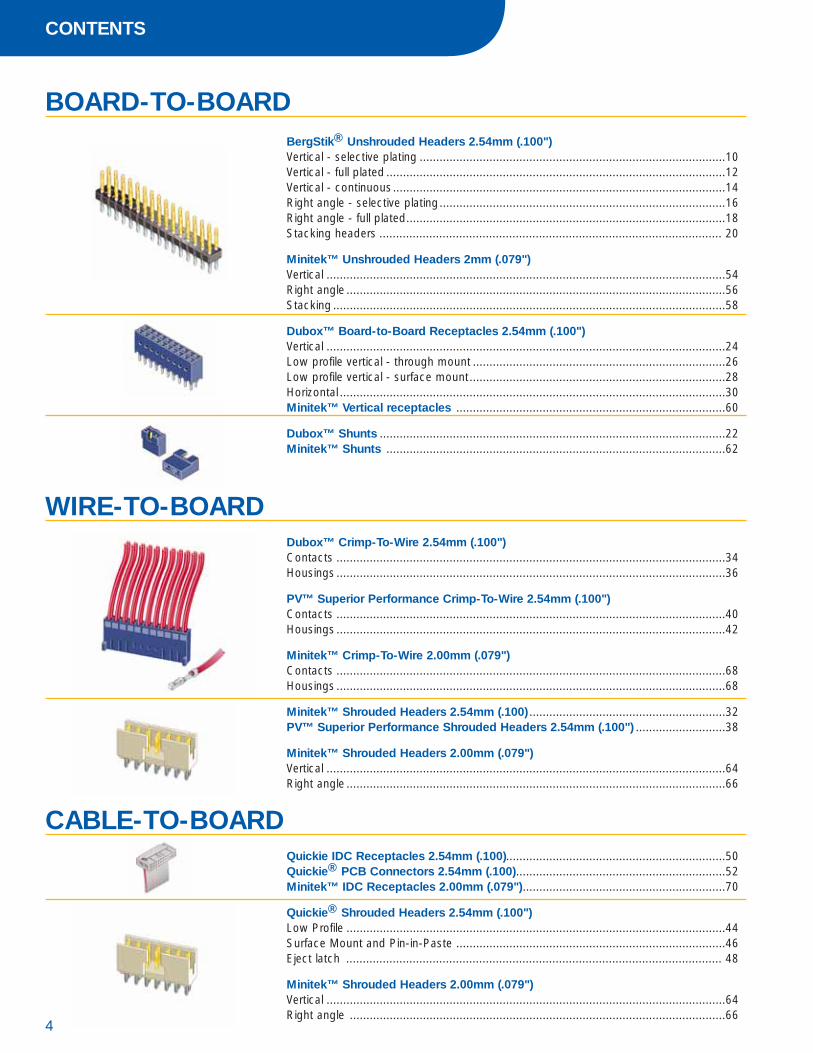
BOARD-TO-BOARDBergStik® Unshrouded Headers 2.54mm (.100")Vertical - selective plating ............................................................................................10Vertical - full plated ......................................................................................................12Vertical - continuous....................................................................................................14Right angle - selective plating......................................................................................16Right angle - full plated................................................................................................18Stacking headers ....................................................................................................... 20
Minitek™ Unshrouded Headers 2mm (.079")Vertical ........................................................................................................................54Right angle ..................................................................................................................56Stacking ......................................................................................................................58
Dubox™ Board-to-Board Receptacles 2.54mm (.100")Vertical ........................................................................................................................24Low profile vertical - through mount ............................................................................26Low profile vertical - surface mount.............................................................................28Horizontal ....................................................................................................................30Minitek™ Vertical receptacles .................................................................................60
Dubox™ Shunts ........................................................................................................22Minitek™ Shunts ......................................................................................................62
WIRE-TO-BOARDDubox™ Crimp-To-Wire 2.54mm (.100")Contacts .....................................................................................................................34Housings .....................................................................................................................36
PV™ Superior Performance Crimp-To-Wire 2.54mm (.100")Contacts .....................................................................................................................40Housings .....................................................................................................................42
Minitek™ Crimp-To-Wire 2.00mm (.079")Contacts .....................................................................................................................68Housings .....................................................................................................................68
Minitek™ Shrouded Headers 2.54mm (.100) ...........................................................32PV™ Superior Performance Shrouded Headers 2.54mm (.100") ...........................38
Minitek™ Shrouded Headers 2.00mm (.079")Vertical ........................................................................................................................64Right angle ..................................................................................................................66
Quickie IDC Receptacles 2.54mm (.100)..................................................................50Quickie® PCB Connectors 2.54mm (.100)...............................................................52Minitek™ IDC Receptacles 2.00mm (.079").............................................................70
Quickie® Shrouded Headers 2.54mm (.100")Low Profile ..................................................................................................................44Surface Mount and Pin-in-Paste .................................................................................46Eject latch ................................................................................................................. 48
Minitek™ Shrouded Headers 2.00mm (.079")Vertical ........................................................................................................................64Right angle .................................................................................................................66
CABLE-TO-BOARD
CONTENTS
4

5Technical / Application Support / Drawings / Specifications / Samples: www.fciconnect.com/basics
WHAT'S NEW ?
Selectively plated headers means youonly get gold on the pin tip where youwant it and not in the solder bath whereyou don't.Pages 10, 11, 16, 17.
SMT Quickie® Low Profile Header.Page 46-47
The Pin-in-Paste Quickie® Low ProfileHeader features a special high tempe-rature housing and is compatible with IR reflow soldering processes.Page 46-47
7.20 mmfor increased board density

APPLICATION OVERVIEW
6
BOARD-TO-BOARD SOLUTIONSPARALLEL
P. 24-29
P. 24-29
P. 10-15
P. 60-61
P. 58-59
P. 54-55
P. 60-61
P. 24-29
P. 20-21
P. 20-21
P. 60-61P. 58-59

7Technical / Application Support / Drawings / Specifications / Samples: www.fciconnect.com/basics
PERPENDICULAR
PLANAR
= 2.54 mm
= 2.00 mm
= Through Mount
= Surface Mount
P. 16-19
P. 56-57
P. 16-19
P. 24-29
P. 60-61
P. 30-31

APPLICATION OVERVIEW
8
WIRE-TO-BOARD SOLUTIONS DISCRETE WIRE
P. 54-55
P. 68-69
P. 68-69
P. 34-37P. 40-43
P. 32-33P. 38-39
P. 34-37P. 40-43
P. 10-15
P. 64-65
P. 56-57
P. 68-69P. 34-37P. 40-43
P. 66-67
P. 68-69P. 10-15 P. 32-33P. 38-39

9
CABLE-TO-BOARD SOLUTIONS FLAT CABLE IDC
P. 50-51
P. 48-49 P. 70-71
P. 70-71
P. 56-57 P. 70-71
P. 66-67
P. 64-65
P. 52-53
P. 48-49
P. 44-47P. 50-51
= 2.54 mm
= 2.00 mm
= Through Mount
= Surface Mount
Technical / Application Support / Drawings / Specifications / Samples: www.fciconnect.com/basics

BergStik® UNSHROUDED HEADERS2.54 mm (.100")
10
TECHNICAL DATAPhysical
Housing: High temperature, black thermoplasticFlammability rating: UL 94 V-0Pin: Phosphor-bronzePlating: Gold or tin over 1.27 µm (50 µ") nickel
Electrical PerformanceCurrent rating: 3 A continuousInsulation resistance: 5000 M� min.Dielectric withstanding voltage: 1500 V
Mechanical PerformancePin retention to housing: 9 N min.
Operating Temperature Range-65°C to +125°C
PackagingStandard: BagsOptional:Tubes or
Tape-and-reel with pick-up cap(SMT pin style 01 only)
Reference InformationFile no. E66906File no. LR46923
Product drawing: By 5-digit base partnumberProduct specification: BUS-12-114Tape and Reel packaging data: TA-840
Specifications subject to change without notice.
MATING DATADubox™ Crimp-to-wire contacts 34Dubox™ Crimp-to-wire housings 36Dubox™ Vertical receptacles 24Dubox™ Low profile vertical receptacles 26, 28Dubox™ Horizontal receptacles 30Quickie™ IDC receptacles 50PV™ Crimp-to-Wire Contacts 40PV™ Crimp-to-Wire Housings 42
PROCESSING INFORMATIONCompatible with wave, vapor-phase,and IR reflow soldering processesRecommended IR profile TA 842 for SMT
RoHs INFORMATIONThis product is RoHs compatible according to the European UnionDirective 2002/95/IEC
TYPICAL APPLICATIONS
Body
solder side
mating side mating side
7.20 mmfor increased board density
VERTICAL SELECTIVE PLATING
2.54
mm
(.100
")

11Technical / Application Support / Drawings / Specifications / Samples: www.fciconnect.com/basics
PART NUMBER
Through mount
Pin style Mating Solder OAL
01 5.84 2.41 10.8018 5.84 3.05 11.4302 5.84 3.42 11.8027 6.60 2.66 11.8222 7.75 3.06 13.3524 6.75 2.90 12.20
1 = 0.76 µm (30µ") gold on mating area, tin on solder side8 = 0.38 µm (15µ") gold on mating area, tin on solder side
02 to 36 = Single row TMT03 to 17 = Single Row SMT04 to 72 = Double row TMT04 to 50 = Double Row SMT08 to 50 = Double Row SMT with pegs
Plating Pin Style5-Digit Base Part Number OptionTotal
Positions LF
Through mount77311 = Single Row77313 = Double Row
Surface mount95293 = Single Row95278 = Double Row98401 = Double Row with pegs
Surface mount
Pin style Mating
01 5.8402 8.08 Option Packaging
- Plastic bagA Tape-and-reel with pick-up capB Tube with pick-up cap
availability on request
77311 101 XXLF
77311 118 XXLF
77311 124 XXLF
77313 101 XXLF
77313 118 XXLF
77313 124 XXLF
95278 101 XXLFA
XX = 04, 06, 08, 10, 12, 16, 20
77311 101 TOTAL POS. LF
77311 118 TOTAL POS. LF
77311 124 TOTAL POS. LF
77313 101 TOTAL POS. LF
77313 118 TOTAL POS. LF
77313 124 TOTAL POS. LF
95278 101 TOTAL POS. LFA
Dimensions in mm
Recommended PCB Layout
0,62 square pin
0,62 square pin
0,62 square pin
2.54
mm
(.100
")

BergStik® UNSHROUDED HEADERS2.54 mm (.100")
12
2.54
mm
(.100
")
VERTICAL FULL PLATING
TECHNICAL DATAPhysical
Housing: High temperature, black thermoplasticFlammability rating: UL 94 V-0Pin: Phosphor-bronzePlating: Gold or tin over 1.27 µm (50µ") nickel
Electrical PerformanceCurrent rating: 3 A continuousInsulation resistance: 5000 M� min.Dielectric withstanding voltage: 1500 V
Mechanical PerformancePin retention to housing: 8.88 N (2 lbf)min.Retentive leg insertion force: >44.48 N max.Retentive leg board retention: 2.22 N
Operating Temperature Range-65°C to +125°C
PackagingStandard: BagsOptional:Tubes or
Tape-and-reel with pick-up cap
Reference InformationFile no. E66906File no. LR46923
Product drawing: By 5-digit base partnumberProduct specification: BUS-12-114
Specifications subject to change without notice.
MATING DATADubox™ Crimp-to-wire contacts 34Dubox™ Crimp-to-wire housings 36Dubox™ Vertical receptacles 24Dubox™ Low profile vertical receptacles 26, 28Dubox™ Horizontal receptacles 30Quickie™ IDC receptacles 50PV™ Crimp-to-Wire Contacts 40PV™ Crimp-to-Wire Housings 42
PROCESSING INFORMATIONCompatible with wave, vapor-phase, andIR reflow soldering processes
RoHs INFORMATIONThis product is RoHs compatible according to the European UnionDirective 2002/95/IEC
TYPICAL APPLICATIONS
Body
solder side
mating side mating side

13Technical / Application Support / Drawings / Specifications / Samples: www.fciconnect.com/basics
2.54
mm
(.100
")
PART NUMBER
01 to 36 = Single row02 to 72 = Double row
1 = 0.76 µm (30µ") gold2 = 0.38 µm (15µ") gold4 = tin
Numberof positions5-Digit Base Part Number Plating HLF
Post Tail OAL
Base PN mm (in.) mm (in.) mm (in.)
68000 5.84 0.230 2.41 0.095 10.80 0.42568001 5.84 0.230 3.05 0.120 11.43 0.45068002 5.84 0.230 3.81 0.150 12.19 0.480
Single Row
Post Tail OAL
Base PN mm (in.) mm (in.) mm (in.)
67996 5.84 0.230 2.41 0.095 10.80 0.42567997 5.84 0.230 3.05 0.120 11.43 0.45068602 5.84 0.230 3.81 0.150 12.19 0.480
Double Row
68000 1XXHLF
68001 1XXHLF
68002 1XXHLF
67996 1XXHLF
67997 1XXHLF
68602 1XXHLF
XX = 04, 06, 08, 10, 12, 16, 20
XX = 04, 06, 08, 10, 12, 16, 20
68000 1XXHLF
68001 1XXHLF
68002 1XXHLF
67996 1XXHLF
67997 1XXHLF
68602 1XXHLF
XX = Total positions
0,62 square pin
0,62 square pin
Dimensions in mm
CONTINUOUS UNSHROUDED HEADERS 2.54 mm (.100")
14
2.54
mm
(.100
")
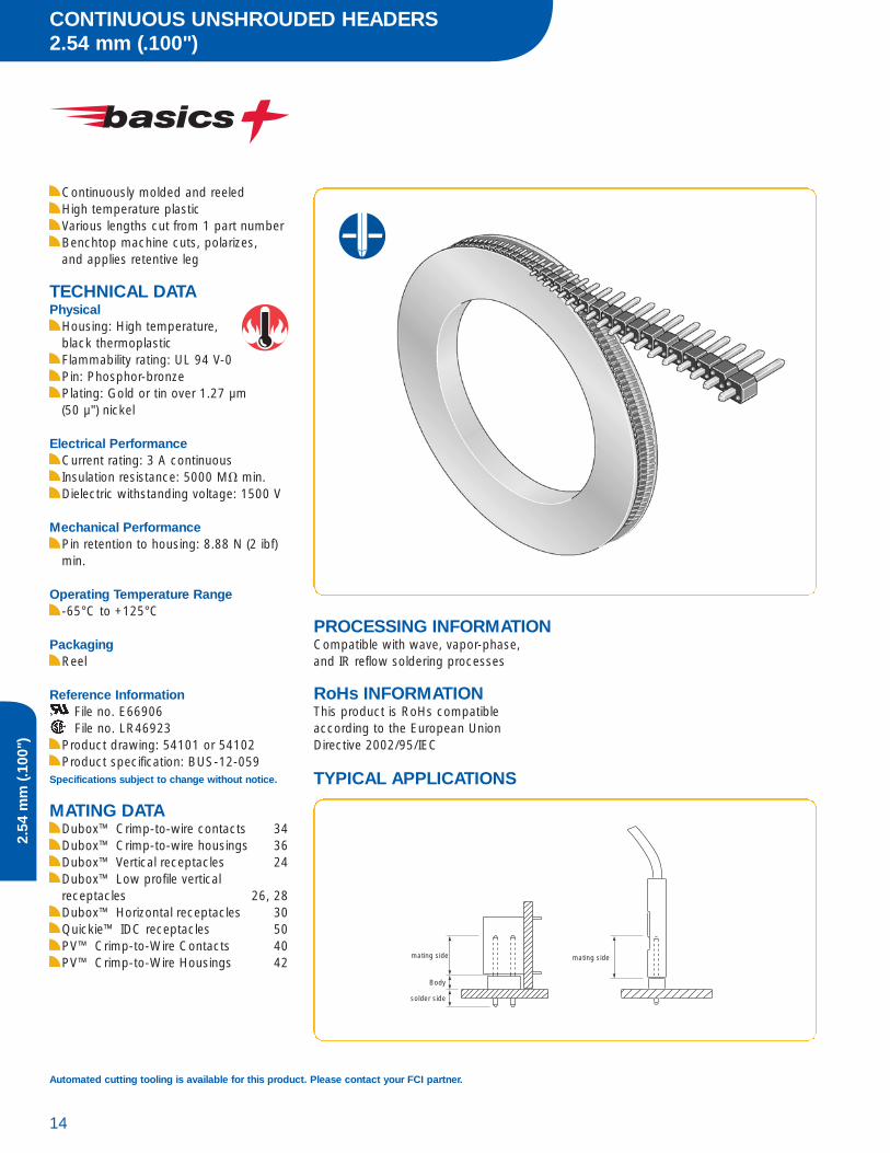
Continuously molded and reeledHigh temperature plasticVarious lengths cut from 1 part numberBenchtop machine cuts, polarizes, and applies retentive leg
TECHNICAL DATAPhysical
Housing: High temperature, black thermoplasticFlammability rating: UL 94 V-0Pin: Phosphor-bronzePlating: Gold or tin over 1.27 µm (50 µ") nickel
Electrical PerformanceCurrent rating: 3 A continuousInsulation resistance: 5000 M� min.Dielectric withstanding voltage: 1500 V
Mechanical PerformancePin retention to housing: 8.88 N (2 ibf)min.
Operating Temperature Range-65°C to +125°C
PackagingReel
Reference InformationFile no. E66906File no. LR46923
Product drawing: 54101 or 54102Product specification: BUS-12-059
Specifications subject to change without notice.
MATING DATADubox™ Crimp-to-wire contacts 34Dubox™ Crimp-to-wire housings 36Dubox™ Vertical receptacles 24Dubox™ Low profile vertical receptacles 26, 28Dubox™ Horizontal receptacles 30Quickie™ IDC receptacles 50PV™ Crimp-to-Wire Contacts 40PV™ Crimp-to-Wire Housings 42
PROCESSING INFORMATIONCompatible with wave, vapor-phase, and IR reflow soldering processes
RoHs INFORMATIONThis product is RoHs compatible according to the European UnionDirective 2002/95/IEC
TYPICAL APPLICATIONS
Body
solder side
mating side mating side
Automated cutting tooling is available for this product. Please contact your FCI partner.

15Technical / Application Support / Drawings / Specifications / Samples: www.fciconnect.com/basics
2.54
mm
(.100
")
PART NUMBER
1 = 0.76 µm (30µ") gold2 = 0.38 µm (15µ") gold4 = tin
0 05-Digit Base Part Number Plating HLF
Post Tail OAL
Base PN mm (in.) mm (in.) mm (in.)
68000 5.84 0.230 2.41 0.095 10.80 0.42568001 5.84 0.230 3.05 0.120 11.43 0.45068002 5.84 0.230 3.81 0.150 12.19 0.480
Single Row
Post Tail OAL
Base PN mm (in.) mm (in.) mm (in.)
67996 5.84 0.230 2.41 0.095 10.80 0.42567997 5.84 0.230 3.05 0.120 11.43 0.45068602 5.84 0.230 3.81 0.150 12.19 0.480
Double Row
68000 100HLF
68001 100HLF
68002 100HLF
67996 100HLF
67997 100HLF
68602 100HLF

BergStik® UNSHROUDED HEADERS2.54 mm (.100")
16
2.54
mm
(.100
")
RIGHT ANGLE SELECTIVE PLATING
High temperature plasticSelective plating
TECHNICAL DATAPhysical
Housing: High temperature, black thermoplasticFlammability rating: UL 94 V-0Pin: Phosphor-bronzePlating: Gold or tin over 1.27 µm (50µ") nickel
Electrical PerformanceCurrent rating: 3 A continuousInsulation resistance: 5000 M� min.Dielectric withstanding voltage: 1500 V
Mechanical PerformancePin retention to housing: 8.88 N min.
Operating Temperature Range-65°C to +125°C
PackagingBags
Reference InformationFile no. E66906File no. LR46923
Product drawing: By 5-digit base partnumberProduct specification: BUS-12-114
Specifications subject to change without notice.
MATING DATADubox™ Crimp-to-wire contacts 34Dubox™ Crimp-to-wire housings 36Dubox™ Vertical receptacles 24Dubox™ Low profile vertical receptacles 26, 28Dubox™ Horizontal receptacles 30Quickie™ IDC receptacles 50PV™ Crimp-to-Wire Contacts 40PV™ Crimp-to-Wire Housings 42
PROCESSING INFORMATIONCompatible with wave, vapor-phase, and IR reflow soldering processes
RoHs INFORMATIONThis product is RoHs compatible according to the European UnionDirective 2002/95/IEC
TYPICAL APPLICATIONS
solder side
solder side
solder side
1.78 mm
mating side
mating side
mating side

17Technical / Application Support / Drawings / Specifications / Samples: www.fciconnect.com/basics
2.54
mm
(.100
")
PART NUMBER
Pin style
77315 77317 Mating Solder
01 03 5.84 2.4118 04 5.84 3.0524 12 6.75 2.90
1 = 0.76 µm (30µ") gold on mating area, tin on solder side4 = tin8 = 0.38 µm (15µ") gold on mating area, tin on solder side
02 to 36 = Single row TMT04 to 72 = Double row TMT
Pin Style
Through mount77315 = Single Row77317 = Double Row
TotalPositions5-Digit Base Part Number Plating LF
Dimensions in mm
Recommended PCB Layout
0,62 square pin
0,62 square pin

BergStik® UNSHROUDED HEADERS2.54 mm (.100")
18
2.54
mm
(.100
")
RIGHT ANGLE FULL PLATING
TECHNICAL DATAPhysical
Housing: High temperature, black thermoplasticFlammability rating: UL 94 V-0Pin: Phosphor-bronzePlating: Gold or tin over 1.27 µm (50µ") nickel
Electrical PerformanceCurrent rating: 3 A continuousInsulation resistance: 5000 M� min.Dielectric withstanding voltage: 1500 V
Mechanical PerformancePin retention to housing: 8.88 N min.Retentive leg insertion force: > 44.48 N max.Retentive leg board retention: > 2.22 N
Operating Temperature Range-65°C to +125°C
PackagingBags
Reference InformationFile no. E66906File no. LR46923
Product drawing: 55101 or 55102Product specification: BUS-12-114
Specifications subject to change without notice.
MATING DATADubox™ Crimp-to-wire contacts 34Dubox™ Crimp-to-wire housings 36Dubox™ Vertical receptacles 24Dubox™ Low profile vertical receptacles 26, 28Dubox™ Horizontal receptacles 30Quickie™ IDC receptacles 50PV™ Crimp-to-Wire Contacts 40PV™ Crimp-to-Wire Housings 42
PROCESSING INFORMATIONCompatible with wave, vapor-phase, and IR reflow soldering processes
RoHs INFORMATIONThis product is RoHs compatible according to the European UnionDirective 2002/95/IEC
TYPICAL APPLICATIONS
solder side
solder side
solder side
1.78 mm
mating side
mating side
mating side

19Technical / Application Support / Drawings / Specifications / Samples: www.fciconnect.com/basics
2.54
mm
(.100
")
PART NUMBER
01 to 36 = Single row02 to 72 = Double row
1 = 0.76 µm (30µ") gold2 = 0.38 µm (15µ") gold4 = tin
PositionsPer row5-Digit Base Part Number Plating HLF
Post Tail
Base PN mm (in.) mm (in.)
68015 5.84 0.230 2.29 0.09568016 5.84 0.230 3.05 0.120
Post Tail
Base PN mm (in.) mm (in.)
68020 5.84 0.230 2.41 0.09568021 5.84 0.230 3.05 0.120
Single Row
Double Row
Recommended PCB Layout
0,62 square pin
0,62 square pin
Dimensions in mm

BergStik® UNSHROUDED STACKING HEADERS2.54 mm (.100")
20
2.54
mm
(.100
")
Wide variety of stack heights in 0.5 mm incrementsHigh temperature plasticSelective plating
TECHNICAL DATAPhysical
Housing: High temperature, black thermoplasticFlammability rating: UL 94 V-0Pin: Phosphor-bronzePlating: Gold or tin over 1.27 µm(50µ") nickel
Electrical PerformanceCurrent rating: 3 A continuousInsulation resistance: 5000 M� min.Dielectric withstanding voltage: 1500 V
Mechanical PerformancePin retention to housing: 9 N min.
Operating Temperature Range-65°C to +125°C
PackagingStandard: Bags
Reference InformationFile no. E66906File no. LR46923
Product drawing: By 5-digit base partnumberProduct specification: BUS-12-114
Specifications subject to change without notice.
MATING DATADubox™ Vertical receptacles 24Dubox™ Low profile vertical receptacles 26,28
PROCESSING INFORMATIONCompatible with wave, vapor-phase, and IR reflow soldering processes
RoHs INFORMATIONThis product is RoHs compatible according to the European UnionDirective 2002/95/IEC
TYPICAL APPLICATIONS
mating sidemating side
OAL OAL
Receptacle
OAL
solder side solder side
BoardSpace
StackHeight
StackHeight

21Technical / Application Support / Drawings / Specifications / Samples: www.fciconnect.com/basics
2.54
mm
(.100
")
PART NUMBER
1 = Single Row (TMT only) 2 = Double Row
1 = Through Hole (TMT)2 = Surface Mount (SMT)
02 to 36 single row (TMT)04 to 72 double row (TMT)04 to 50 double row (SMT
XX.XX = mmSpecify mmi.e. 08.50 = 8.50 mm in 0.50 mm incrementsTMT = 08.00 min. - 25.00 max.SMT = 09.50 min. - 26.00 max.
1 = 2.41 mm2 = 3.05 mm4 = SMT (double row only)
Pin OAL (TMT) OAL (SMT)Style mm mm01 12.20 10.4202 13.50 11.7203 15.90 14.1204 16.76 14.9805 17.65 15.8706 18.91 17.1307 20.96 19.1808 23.50 21.7209 26.04 24.2610 28.58 26.8011 31.12 29.3412 33.66 31.88
5 4 LeadSolder Side
Option
RowOption Plating Pin Style
TotalPositions Stack Height
1 = 0.76 µm (30µ") gold on mating area, tin on solder side8 = 0.38 µm (15µ") gold on mating area, tin on solder side
LF
Step-by-Step Design1. Determine desired board spacing
(0.50 mm increments)2. Select Dubox™ receptacle and calculate
stack height Stack Height = Board Spacing – Receptacle Height
3. Find the insertion depth from the chart below. Calculate max./min. OALOAL = Stack Height + solder side + InsertionDepth
4. Select the Pin Style with OAL between max. and min. values
Example:1. Application requires a board spacing of 22.50 2. Select the Dubox™ Low Profile Receptacle
with height of 7.00 The Header Stack Height is 22.50 - 7.00 = 15.50
3. For standard board applications, the 3.05 solderside is selectedOAL (max.) = 15.50 + 3.05 + 6.10 = 24.65OAL (min.) = 15.50 + 3.05 + 3.86 = 22.41
4. Select Pin Style 08 with OAL = 23.505. Part Number is 54122-108721550LF
Recommended PCB Layout
Dubox™ RECEPTACLES
Low Profile Vertical
Height 7.00 8.50Insertion Depth (max.) 6.10 6.10 Insertion Depth (min.) 3.86 4.34
Dimensions in mm
SHUNTS 2.54 mm (.100")
22
2.54
mm
(.100
")
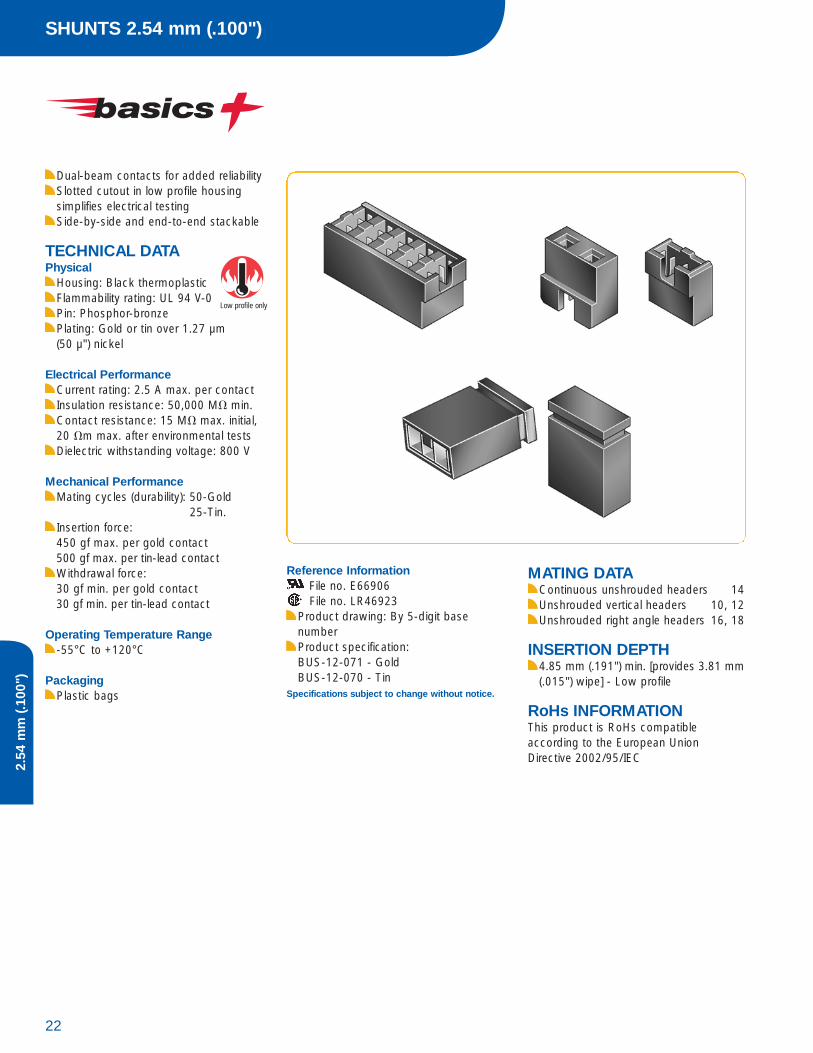
Dual-beam contacts for added reliabilitySlotted cutout in low profile housingsimplifies electrical testingSide-by-side and end-to-end stackable
TECHNICAL DATAPhysical
Housing: Black thermoplasticFlammability rating: UL 94 V-0Pin: Phosphor-bronzePlating: Gold or tin over 1.27 µm (50 µ") nickel
Electrical PerformanceCurrent rating: 2.5 A max. per contactInsulation resistance: 50,000 M� min.Contact resistance: 15 M� max. initial,20 �m max. after environmental testsDielectric withstanding voltage: 800 V
Mechanical PerformanceMating cycles (durability): 50-Gold
25-Tin.Insertion force:450 gf max. per gold contact500 gf max. per tin-lead contactWithdrawal force:30 gf min. per gold contact30 gf min. per tin-lead contact
Operating Temperature Range-55°C to +120°C
PackagingPlastic bags
Reference InformationFile no. E66906File no. LR46923
Product drawing: By 5-digit base numberProduct specification: BUS-12-071 - GoldBUS-12-070 - Tin
Specifications subject to change without notice.
Low profile only
MATING DATAContinuous unshrouded headers 14Unshrouded vertical headers 10, 12Unshrouded right angle headers 16, 18
INSERTION DEPTH4.85 mm (.191") min. [provides 3.81 mm(.015") wipe] - Low profile
RoHs INFORMATIONThis product is RoHs compatible according to the European UnionDirective 2002/95/IEC
23Technical / Application Support / Drawings / Specifications / Samples: www.fciconnect.com/basics
2.54
mm
(.100
")
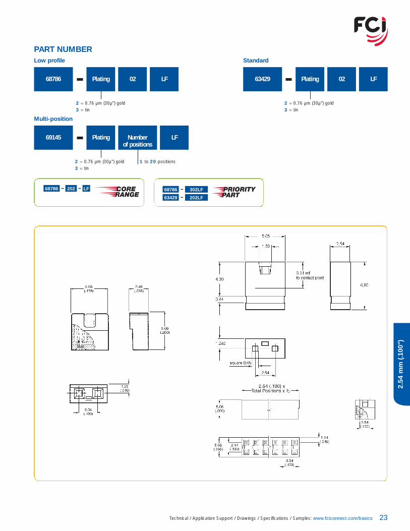
PART NUMBER
68786 Plating 02 LF
2 = 0.76 µm (30µ") gold3 = tin
Low profile
63429 Plating 02 LF
2 = 0.76 µm (30µ") gold3 = tin
69145 Number of positions
Plating LF
2 = 0.76 µm (30µ") gold3 = tin
1 to 20 positions
Standard
Multi-position
68786 302LF
63429 202LF
68786 202 LF
Dubox™ VERTICAL RECEPTACLES2.54 mm (.100")
24
2.54
mm
(.100
")
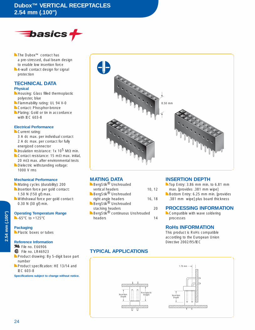
The Dubox™ contact has a pre-stressed, dual beam design to enable low insertion force4-wall contact design for signal protection
TECHNICAL DATAPhysical
Housing: Glass filled thermoplasticpolyester, blueFlammability rating: UL 94 V-0Contact: Phosphor-bronzePlating: Gold or tin in accordancewith IEC 603-8
Electrical PerformanceCurrent rating: 3 A dc max. per individual contact2 A dc max. per contact for fully energized connectorInsulation resistance: 1x 10⁵ M� min.Contact resistance: 15 m� max. initial,20 m� max. after environmental testsDielectric withstanding voltage: 1000 V rms
Mechanical PerformanceMating cycles (durability): 200Insertion force per gold contact: 1.50 N (150 gf) max.Withdrawal force per gold contact: 0.30 N (30 gf) min.
Operating Temperature Range-65°C to +125°C
PackagingPlastic boxes or tubes
Reference InformationFile no. E66906File no. LR46923
Product drawing: By 5-digit base partnumberProduct specification: HE 13/14 andIEC 603-8
Specifications subject to change without notice.
MATING DATABergStik® Unshrouded vertical headers 10, 12BergStik® Unshrouded right angle headers 16, 18BergStik® Unshrouded stacking headers 20BergStik® continuous Unshrouded headers 14
INSERTION DEPTHTop Entry: 3.86 mm min. to 6.81 mmmax. [provides .381 mm wipe]Bottom Entry: 6.25 mm min. [provides.381 mm wipe] plus board thickness
PROCESSING INFORMATIONCompatible with wave soldering processes
RoHs INFORMATIONThis product is RoHs compatible according to the European UnionDirective 2002/95/IEC
Insertion Depth
ReceptacleHeight
1.78 mm
InsertionDepth
8.50 mm
TYPICAL APPLICATIONS

25Technical / Application Support / Drawings / Specifications / Samples: www.fciconnect.com/basics
2.54
mm
(.100
")Dimensions in mm
5-Digit Base Part Number PositionsPer Row
02 to 5075915 = Single Row, Top Entry71920 = Single Row, Dual Entry87606 = Double Row, Top Entry89891 = Double Row, Dual Entry
Plating
3 = 0,76 µm (30µ") gold on mating area,tin on solder side
4 = tin
LF
PART NUMBER
Recommended PCB Layout

Dubox™ LOW PROFILE VERTICAL RECEPTACLES2.54 mm (.100")
26
2.54
mm
(.100
")
The Dubox™ contact has a pre-stressed, dual beam design to enable low insertion force4-wall contact design for signalprotection
TECHNICAL DATAPhysical
Housing: Glass filled thermoplasticFlammability rating: UL 94 V-0Contact: Phosphor-bronzePlating: Gold or tin over 1.27 µm (50 µ") nickel
Electrical PerformanceCurrent rating: 3 A dc max. per individual contact2 A dc max. per contact for fully energized connectorInsulation resistance: 1x 10⁵ M� min.Contact resistance: 15 m� max. initial,20 m� max. after environmental testsDielectric withstanding voltage: 1000 V rms
Mechanical PerformanceMating cycles (durability): 200Insertion force per gold contact: 1.50 N (150 gf) avg.Withdrawal force per gold contact: 0.30 N (30 gf) min.
Operating Temperature Range-65°C to +125°C
PackagingPlastic boxes or tubes
Reference InformationFile no. E66906File no. LR46923
Product drawing: By 5-digit base partnumberProduct specification: BUS-12-055
Specifications subject to change without notice.
MATING DATABergStik® Unshrouded vertical headers 10, 12BergStik® Unshrouded right angle headers 16, 18BergStik® Unshrouded stacking headers 20BergStik® continuous Unshrouded headers 14
INSERTION DEPTHTop Entry: 3.86 mm min. to 6.10 mmmax. [provides .381 mm wipe]Bottom Entry: 5.08 mm min. [provides .381 mm wipe] plus boardthickness
PROCESSING INFORMATIONCompatible with wave soldering processes
RoHs INFORMATIONThis product is RoHs compatible according to the European UnionDirective 2002/95/IEC
Low profile 7.0 mm for closer board stacking
TYPICAL APPLICATIONS
Insertion Depth
ReceptacleHeight
1.78 mm
InsertionDepth
ReceptacleHeight Insertion
Depth

27Technical / Application Support / Drawings / Specifications / Samples: www.fciconnect.com/basics
2.54
mm
(.100
")
PART NUMBER
5-Digit Base Part Number PositionsPer Row
02 to 5076341 = Single Row, Top Entry76342 = Double Row, Top Entry71991 = Double Row, Dual Entry
Plating
3 = 0,76 µm (30µ") gold on mating area,tin on solder side
4 = tin
LF
71991 3XXLFXX = 05 - 20
Dimensions in mm
Recommended PCB Layout
P/N 76341Top Entry
P/N 76342Top Entry
P/N 71991Dual Entry
P/N 76341Top Entry
P/N 76342Top Entry
P/N 71991Dual Entry

Dubox™ LOW PROFILE VERTICAL RECEPTACLES2.54 mm (.100")
28
2.54
mm
(.100
")
The Dubox™ contact has a pre-stressed, dual beam design to enable low insertion forceFloating solder tails self-center on circuit pads and assure coplanarity4-wall contact design for signal protection
TECHNICAL DATAPhysical
Housing: High-temperature, grey thermoplasticFlammability rating: UL 94 V-0Contact: Phosphor-bronzePlating: Gold or tin over 1.27 µm (50 µ") nickel
Electrical PerformanceCurrent rating: 3 A dc max. per individual contact2 A dc max. per contact for fully energized connectorInsulation resistance: 1x 10⁵ M� min.Contact resistance: 15 m� max. initial,20 m� max. after environmental testsDielectric withstanding voltage: 1000 V rms
Mechanical PerformanceMating cycles (durability): 200Insertion force per gold contact: 1.50 N (150 gf) avg.Withdrawal force per gold contact: 0.30 N (30 gf) min.
Operating Temperature Range-65°C to +125°C
PackagingTubes,Tape on Reel or plastic boxes
Reference InformationFile no. E66906File no. LR46923
Product drawing: By 5-digit base partnumberProduct specification: BUS-12-055Tape and Reel packaging data : TA-856
Specifications subject to change without notice.
MATING DATABergStik® Unshrouded vertical headers 10, 12BergStik® Unshrouded right angle headers 16, 18BergStik® Unshrouded stacking headers 20BergStik® continuous Unshrouded headers 14
INSERTION DEPTHTop Entry: 3.86 mm min. to 6.10 mmmax. [provides .381 mm wipe]Bottom Entry: 5.08 mm min.[provides .381 mm wipe] plus boardthickness
PROCESSING INFORMATIONCompatible with wave, vapor-phase,and IR reflow soldering processesRecommended IR profile: TA-842
RoHs INFORMATIONThis product is RoHs compatible accor-ding to the European Union Directive2002/95/IEC
TYPICAL APPLICATIONS
ReceptacleHeight Insertion
Depth
optional hold down
Low profile 7.0 mm for closer board stacking

29Technical / Application Support / Drawings / Specifications / Samples: www.fciconnect.com/basics
2.54
mm
(.100
")
5-Digit Base Part Number PositionsPer Row
02 to 25 Single Row02 to 25 Double Row
91601 = Single Row, Dual Entry91614 = Single Row with external Hold Downs, Dual Entry89898 = Double Row, Dual Entry91615 = Double Row with External Hold Downs, Dual Entry91618 = Double Row with Internal Hold Downs, Dual Entry
Plating Option
3 = 0,76 µm (30µ") gold on mating area, tin on solder side4 = tin
A = Tape-and-Reel packaging with pick-up cap(standard-tubes)
LF
PART NUMBER
89898 3XXALF
XX = 02, 03, 04, 05, 06, 08, 10
89898 3XXALF
XX = 11 - 20
Dimensions in mm
Standard
External Hold Downs91614 91615
Single Row + Pad lay-outs Double Row + Pad lay-outs
*Note: available as of 3 position versions
not available in single row
*Note: available as of 3 position versions
*Note: available as of 6 number of positions
91601 89898
91615Internal Hold Downs
Note:All dimensions marked with * are minimum dimensions

Dubox™ HORIZONTAL RECEPTACLES2.54 mm (.100")
30
2.54
mm
(.100
")
The Dubox™ contact has a pre-stressed, dual beam design to enable low insertion forceFloating solder tails self-center on circuit pads and assure coplanarity4-wall contact design for signal protection
TECHNICAL DATAPhysical
Housing: Blue thermoplastic -Through holeHigh temperature grey thermoplastic - Surface mountFlammability rating: UL 94 V-0Contact: Phosphor-bronzePlating: Gold or tin over 1.27 µm (50 µ") nickel
Electrical PerformanceCurrent rating: 3 A dc max. per individual contact2 A dc max. per contact for fully energized connectorInsulation resistance: 1x 10⁵ M� min.Contact resistance: 15 m� max. initial,20 m� max. after environmental testsDielectric withstanding voltage: 1000 V
Mechanical PerformanceMating cycles (durability): 200Insertion force per gold contact: 1.50 N (150 gf)Withdrawal force per gold contact: 0.30 N (30 gf)
Operating Temperature Range-65°C to +125°C
PackagingStandard: TubesOptional: Tape-and-reel
Reference InformationFile no. E66906File no. LR46923
Product drawing: 71607, 71609,89882, 89883Product specification: HE 13/14 andIEC 603-8Application specification: TA-842 for SMTTape and Reel packaging data : TA-856
Specifications subject to change without notice.
MATING DATABergStik® Unshrouded vertical headers 10, 12BergStik® Unshrouded right angle headers 16, 18BergStik® continuousUnshrouded headers 14
INSERTION DEPTH5.00 mm min. to 7.50 mm max. [provides .381 mm wipe]
PROCESSING INFORMATIONSeries 89882, 89883: compatible withwave soldering processesSeries 71607, 71609: compatible withwave, vapor-phase and IR reflow solde-ring processes
RoHs INFORMATIONThis product is RoHs compatible according to the European UnionDirective 2002/95/IEC
TYPICAL APPLICATIONS
InsertionDepth
InsertionDepth

31Technical / Application Support / Drawings / Specifications / Samples: www.fciconnect.com/basics
2.54
mm
(.100
")
PART NUMBER
5-Digit Base Part Number PositionsPer Row
02 to 50 (TMT)02 to 40 (SMT)
89882 = Through Hole (TMT), Single Row89883 = Through Hole (TMT), Double Row
71607 = Surface Mount (SMT), Single Row 71609 = Surface Mount (SMT), Double Row
Plating
3 = 0,76 µm (30µ") gold on mating area,tin on solder side
4 = tin (TMT only)
LF
Dimensions in mm
Recommended PCB Layout
89882
89883
71607
71609

Dubox™ SHROUDED HEADERS2.54 mm (.100")
32
2.54
mm
(.100
")
For use with Dubox™ crimp-to-wirehousingsStackable end-to-endPassive latching, anti-reverse and anti-miss-match when used withDubox™ crimp-to-wire housingsSelective plating
TECHNICAL DATAPhysical
Housing: Glass filled thermoplasticpolyesterHousing color for series 76382, 76383:blueHousing color for series 76384, 76385:blackFlammability rating: UL 94 V-0Contact: Phosphor-bronzePlating: Gold or tin over 1.27 µm (50µ") nickel
Electrical PerformanceCurrent rating: 3 A continuous Insulation resistance: 1x 10⁵ M� min.Dielectric withstanding voltage: 1000 V rms
Mechanical PerformanceContact retention to housing: 20 N min.
Operating Temperature Range-40°C to +125°C
PackagingTube
Reference InformationFile no. E66906File no. LR46923
Product drawing: By 5-digit base partnumberApplication specification: TA-531
Specifications subject to change without notice.
MATING DATADubox™ Crimp-to-wire contacts 34Dubox™ Crimp-to-wire housings 36
PROCESSING INFORMATIONCompatible with wave soldering processes
RoHs INFORMATIONThis product is RoHs compatible according to the European UnionDirective 2002/95/IEC
33Technical / Application Support / Drawings / Specifications / Samples: www.fciconnect.com/basics
2.54
mm
(.100
")
PART NUMBER
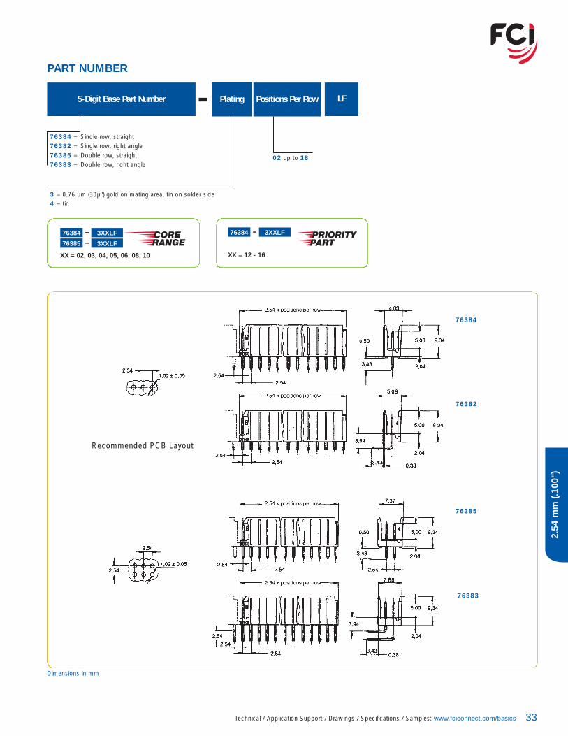
02 up to 18
Plating5-Digit Base Part Number Positions Per Row
76384 = Single row, straight76382 = Single row, right angle76385 = Double row, straight76383 = Double row, right angle
3 = 0.76 µm (30µ") gold on mating area, tin on solder side4 = tin
LF
76384 3XXLF
76385 3XXLF
XX = 02, 03, 04, 05, 06, 08, 10
76384 3XXLF
XX = 12 - 16
Dimensions in mm
76384
76382
76385
76383
Recommended PCB Layout

Dubox™ CRIMP-TO-WIRE CONTACTS2.54 mm (.100")
34
2.54
mm
(.100
")
The Dubox™ contact has a pre-stressed, dual beam design to enable low insertion force.Mates with very short pins (5 mm)Universal crimp barrel accomodateswires from AWG 22-30Selective plating
TECHNICAL DATAPhysical
Contact: phosphor bronzePlating: 0.76 µm (30µ") Gold over 1.27 µm (50 µ") nickel
Electrical PerformanceCurrent rating: 3 A continuousContact resistance after environmentaltest: 15 m� max. – ContactDielectric withstanding voltage: 1000 V rms
Mechanical PerformanceMating cycles (durability): 200 – GoldInsertion force gold finish contact: 1.3 NWithdrawal force (min) gold finishcontact: 0.3 N
Operating Temperature Range-65°C to +125°C
PackagingReelsBoxes - Loose piece
Reference InformationFile no. E66906File no. LR46923
Product drawing: By 5-digit base partnumberProduct specification: BUS-12-055Application specification: TA-317, TA-340
Specifications subject to change without notice.
MATING DATABergStik® unshrouded straight headers 10, 12BergStik® unshrouded right angle headers 16, 18Dubox™ shrouded vert./ra. headers 32BergStik® continuous unshrouded headers 14
INSERTION DEPTHDiscrete Wire: 3.56 mm min. to 5.59mm max. [provides .381 mm wipe]Crimp-to-Wire Housing: 5.08 mm min. to 6.22 mm max. [provides .381 mmwipe in housing]
RoHs INFORMATIONThis product is RoHs compatible according to the European UnionDirective 2002/95/IEC
TYPICAL APPLICATIONS
Insertion Depth
35Technical / Application Support / Drawings / Specifications / Samples: www.fciconnect.com/basics
2.54
mm
(.100
")
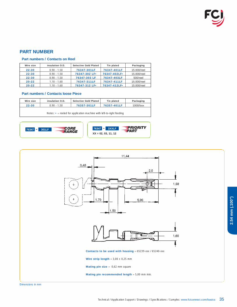
PART NUMBER
Wire size insulation O.D. Selective Gold Plated Tin plated Packaging
22-30 0.90 - 1.50 76347-301LF 76347-401LF 15.000/reel22-30 0.90 - 1.50 76347-302 LF• 76347-402LF• 15.000/reel22-30 0.90 - 1.50 76347-303 LF 76347-403LF 500/reel20-22 1.10 - 1.60 76347-311LF 76347-411LF 15.000/reel20-22 1.10 - 1.60 76347-312 LF• 76347-412LF• 15.000/reel
Part numbers / Contacts loose Piece
Wire size insulation O.D. Selective Gold Plated Tin plated Packaging
22-30 0.90 - 1.50 76357-301LF 76357-401LF 1000/box
Notes: • = reeled for application machine with left-to-right feeding
Part numbers / Contacts on Reel
76347 301LF 76347 3XXLF
XX = 02, 03, 11, 12
Dimensions in mm
Contacts to be used with housing = 65239-xxx / 65240-xxx
Wire strip length = 3,00 ± 0,25 mm
Mating pin size = 0,62 mm square
Mating pin recommended length = 5,00 mm min.

Dubox™ CRIMP-TO-WIRE HOUSINGS2.54 mm (.100")
36
2.54
mm
(.100
")
For use with Dubox™ crimp-to-wirecontactsStackable end-to-endPassive latching, anti-reverse and anti-miss-match when used with Dubox™ shrouded headersContacts removable for easy repairability
TECHNICAL DATAPhysical
Housing: Glass filled thermoplasticpolyester, blue
Flammability rating: UL 94 V-0
Electrical PerformanceInsulation resistance: 1x 10⁵ M� minDielectric withstanding voltage:1000 V rms
Operating Temperature Range-65°C to +125°C
PackagingBulk
Reference InformationFile no. E66906File no. LR46923
Product drawing: By 5-digit base partnumberApplication specification: TA-317, TA-340
Specifications subject to change without notice.
MATING DATABergStik® unshrouded vertical headers 10, 12BergStik® unshrouded right angle headers 16, 18Dubox™ shrouded headers 32
INSERTION DEPTH4.0 mm min. to 6.0 mm max.
RoHs INFORMATIONThis product is RoHs compatible according to the European UnionDirective 2002/95/IEC
InsertionDepth
InsertionDepth
InsertionDepth
TYPICAL APPLICATIONS

37Technical / Application Support / Drawings / Specifications / Samples: www.fciconnect.com/basics
2.54
mm
(.100
")
PART NUMBER
Dimensions in mm
Pin size: 0.62 mm square
Recommended pin length: 5.00 mm min.
02 up to 36
05-Digit Base Part Number Positions Per Row
65240 = Single row65239 = Double row
LF
65239 0XXLF
65240 0XXLF
65239 0XXLF
XX = 02 - 18
XX = 02, 03, 04, 05, 06, 08, 10
XX = 04, 06, 08, 10, 12, 16, 20
PV™ SHROUDED HEADERS2.54 mm (.100")
38
2.54
mm
(.100
")
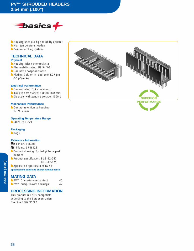
Housing uses our high reliability contactHigh temperature headersPassive latching system
TECHNICAL DATAPhysical
Housing: Black thermoplasticFlammability rating: UL 94 V-0Contact: Phosphor-bronzePlating: Gold or tin-lead over 1.27 µm(50 µ”) nickel
Electrical PerformanceCurrent rating: 3 A continuousInsulation resistance: 100000 m� min.Dielectric withstanding voltage: 1000 V
Mechanical PerformanceContact retention to housing: 17.76 N min.
Operating Temperature Range-40°C to +95°C
PackagingBags
Reference InformationFile no. E66906File no. LR46923
Product drawing: By 5-digit base partnumberProduct specification: BUS-12-067
BUS-12-075Application specification: TA-531
Specifications subject to change without notice.
MATING DATAPV™ Crimp-to-wire contact 40PV™ crimp-to-wire housings 42
PROCESSING INFORMATIONThis product is RoHs compatible according to the European UnionDirective 2002/95/IEC

39Technical / Application Support / Drawings / Specifications / Samples: www.fciconnect.com/basics
2.54
mm
(.100
")
Vertical69167 = Single Row69168 = Double Row
Right Angle78208 = Single Row78207 = Double Row
Plating5-Digit Base Part Number
Housings
5-Digit Base Part Number
78211 = Single Row65846 = Double Row
TotalPositions
03 to 15 (Single Row)06 to 30 (Double Row)
0
1 = 0.76 µm (30 µ") Gold
4 = tin
03 to 15 (Single Row)06 to 30 (Double Row)
HLF
LF
PART NUMBER
TotalPositions
PV™ CRIMP-TO-WIRE CONTACTS2.54 mm (.100")
40
2.54
mm
(.100
")
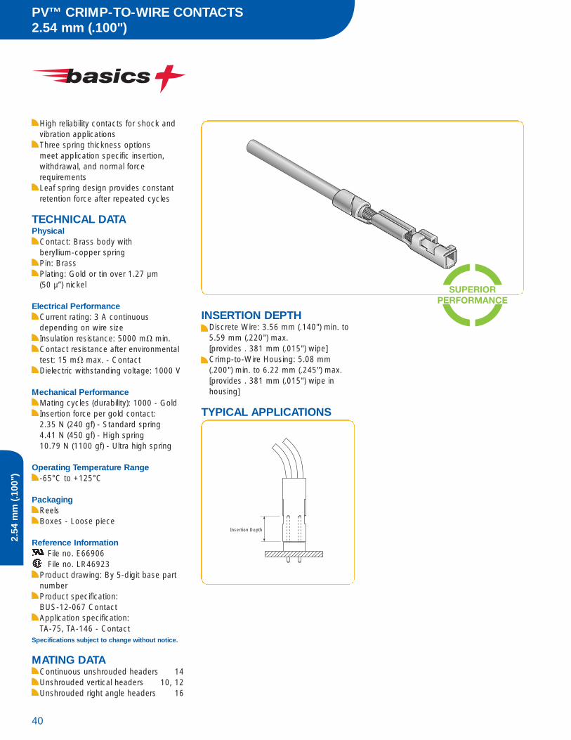
High reliability contacts for shock andvibration applicationsThree spring thickness options meet application specific insertion, withdrawal, and normal force requirementsLeaf spring design provides constantretention force after repeated cycles
TECHNICAL DATAPhysical
Contact: Brass body with beryllium-copper springPin: BrassPlating: Gold or tin over 1.27 µm (50 µ”) nickel
Electrical PerformanceCurrent rating: 3 A continuous depending on wire sizeInsulation resistance: 5000 m� min.Contact resistance after environmentaltest: 15 m� max. - ContactDielectric withstanding voltage: 1000 V
Mechanical PerformanceMating cycles (durability): 1000 - GoldInsertion force per gold contact:2.35 N (240 gf) - Standard spring4.41 N (450 gf) - High spring10.79 N (1100 gf) - Ultra high spring
Operating Temperature Range-65°C to +125°C
PackagingReelsBoxes - Loose piece
Reference InformationFile no. E66906File no. LR46923
Product drawing: By 5-digit base partnumberProduct specification: BUS-12-067 ContactApplication specification: TA-75, TA-146 - Contact
Specifications subject to change without notice.
MATING DATAContinuous unshrouded headers 14Unshrouded vertical headers 10, 12Unshrouded right angle headers 16
INSERTION DEPTHDiscrete Wire: 3.56 mm (.140") min. to5.59 mm (.220") max. [provides . 381 mm (.015") wipe]Crimp-to-Wire Housing: 5.08 mm(.200") min. to 6.22 mm (.245") max.[provides . 381 mm (.015") wipe in housing]
TYPICAL APPLICATIONS
Insertion Depth
41Technical / Application Support / Drawings / Specifications / Samples: www.fciconnect.com/basics
2.54
mm
(.100
")
PART NUMBER
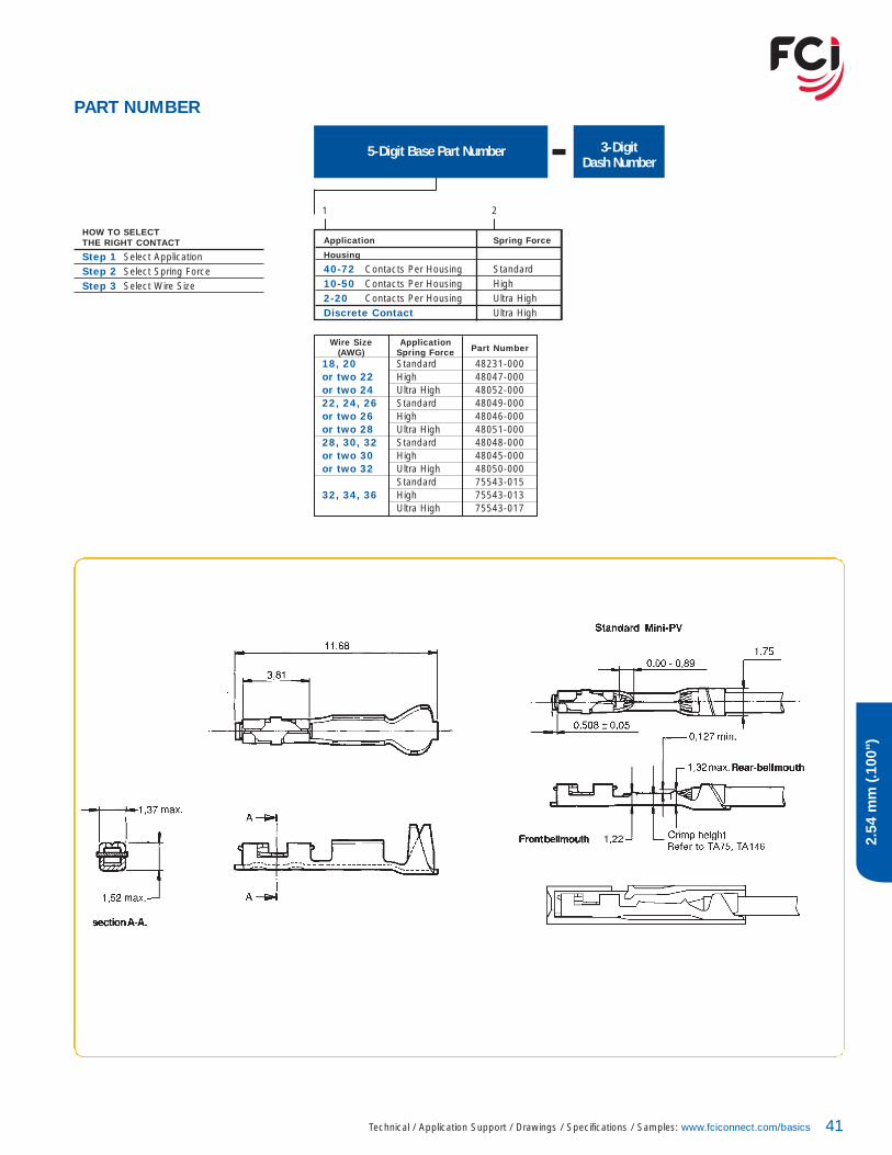
5-Digit Base Part Number 3-DigitDash Number
Application Spring Force
Housing
40-72 Contacts Per Housing Standard10-50 Contacts Per Housing High2-20 Contacts Per Housing Ultra HighDiscrete Contact Ultra High
HOW TO SELECT THE RIGHT CONTACT
Step 1 Select ApplicationStep 2 Select Spring ForceStep 3 Select Wire Size
Wire Size Application(AWG) Spring Force Part Number
18, 20 Standard 48231-000or two 22 High 48047-000or two 24 Ultra High 48052-00022, 24, 26 Standard 48049-000or two 26 High 48046-000or two 28 Ultra High 48051-00028, 30, 32 Standard 48048-000or two 30 High 48045-000or two 32 Ultra High 48050-000
Standard 75543-01532, 34, 36 High 75543-013
Ultra High 75543-017
1 2
PV™ CRIMP-TO-WIRE HOUSINGS2.54 mm (.100")
42
2.54
mm
(.100
")
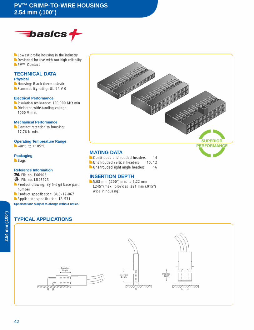
Lowest profile housing in the industryDesigned for use with our high reliabilityPV™ Contact
TECHNICAL DATAPhysical
Housing: Black thermoplastic Flammability rating: UL 94 V-0
Electrical PerformanceInsulation resistance: 100,000 M� minDielectric withstanding voltage: 1000 V min.
Mechanical PerformanceContact retention to housing:17.76 N min.
Operating Temperature Range-40°C to +105°C
PackagingBags
Reference InformationFile no. E66906File no. LR46923
Product drawing: By 5-digit base partnumberProduct specification: BUS-12-067 Application specification: TA-531
Specifications subject to change without notice.
MATING DATAContinuous unshrouded headers 14Unshrouded vertical headers 10, 12Unshrouded right angle headers 16
INSERTION DEPTH5.08 mm (.200") min. to 6.22 mm(.245") max. [provides .381 mm (.015")wipe in housing]
InsertionDepth
InsertionDepth
InsertionDepth
TYPICAL APPLICATIONS

43Technical / Application Support / Drawings / Specifications / Samples: www.fciconnect.com/basics
2.54
mm
(.100
")
Single Row Double Row
Total65039 78211
Total65043 65846
Positions Positions
1 -036 4 -035 -0142 -035 6 -034 -0153 -034 -003 8 -033 -0164 -033 -004 10 -032 -0105 -032 -005 12 -031 -0176 -031 -006 14 -030 -0077 -030 -007 16 -029 -0118 -029 -008 18 -028 -0089 -028 -009 20 -027 -00610 -027 -010 22 -026 -01811 -026 -011 24 -025 -00112 -025 -012 26 -024 -01913 -024 -013 28 -023 -02014 -023 -014 30 -022 -00215 -022 -015 32 -021 -02116 -021 34 -020 -02217 -020 36 -019 -02318 -019 38 -018 -003
PART NUMBER
3-DigitDash Number
LF5-Digit Base Part Number
65039 = Single Row78211 = Single Row with Center Key65043 = Double Row65846 = Double Row with Center Key
Single Row Double Row
Total65039 78211
Total65043 65846
Positions Positions
19 -018 40 -017 -02420 -017 42 -016 -02521 -016 44 -015 -00422 -015 46 -014 -02623 -014 48 -013 -02724 -013 50 -012 -01225 -012 52 -011 -02826 -011 54 -010 -00527 -010 56 -009 -02928 -009 58 -008 -03029 -008 60 -007 -01330 -007 62 -006 -03131 -006 64 -005 -00932 -005 66 -004 -03233 -004 68 -003 -03334 -003 70 -002 -03435 -002 72 -001 -03536 -001
Quickie™ SHROUDED LOW PROFILE HEADERS2.54 mm (.100")
44
2.54
mm
(.100
")
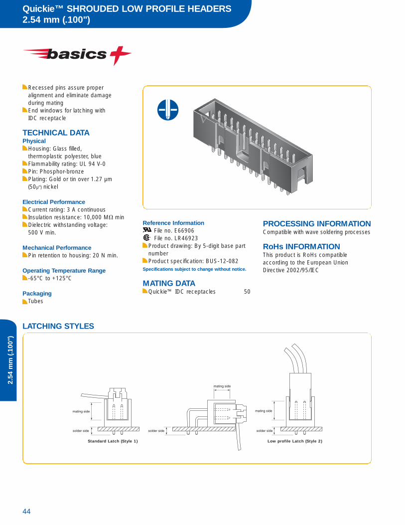
Recessed pins assure proper alignment and eliminate damage during matingEnd windows for latching with IDC receptacle
TECHNICAL DATAPhysical
Housing: Glass filled, thermoplastic polyester, blueFlammability rating: UL 94 V-0Pin: Phosphor-bronzePlating: Gold or tin over 1.27 µm (50µ") nickel
Electrical PerformanceCurrent rating: 3 A continuousInsulation resistance: 10,000 M� minDielectric withstanding voltage:500 V min.
Mechanical PerformancePin retention to housing: 20 N min.
Operating Temperature Range-65°C to +125°C
PackagingTubes
Reference InformationFile no. E66906File no. LR46923
Product drawing: By 5-digit base partnumberProduct specification: BUS-12-082
Specifications subject to change without notice.
MATING DATAQuickie™ IDC receptacles 50
LATCHING STYLES
Standard Latch (Style 1) Low profile Latch (Style 2)
PROCESSING INFORMATIONCompatible with wave soldering processes
RoHs INFORMATIONThis product is RoHs compatible according to the European UnionDirective 2002/95/IEC

45Technical / Application Support / Drawings / Specifications / Samples: www.fciconnect.com/basics
2.54
mm
(.100
")
PART NUMBER
1 = 0.76 µm (30µ") gold on mating area, tin on solder side2 = tin 3 = 0.38 µm (15µ") gold on mating area, tin on solder side
30 = 4 pos.31 = 6 pos.32 = 8 pos.01 = 10 pos.02 = 14 pos.03 = 16 pos.04 = 20 pos.05 = 26 pos. 06 = 34 pos.07 = 40 pos.08 = 50 pos.09 = 60 pos.10 = 64 pos.
Plating5-Digit Base Part Number TotalPositions
Through mount75869 = Vertical75867 = Right angle
LF
Dimensions in mm
Recommended PCB Layout
Vertical Right Angle
Quickie™ SMT/PiP LOW PROFILE HEADERS2.54 mm (.100")
46
2.54
mm
(.100
")
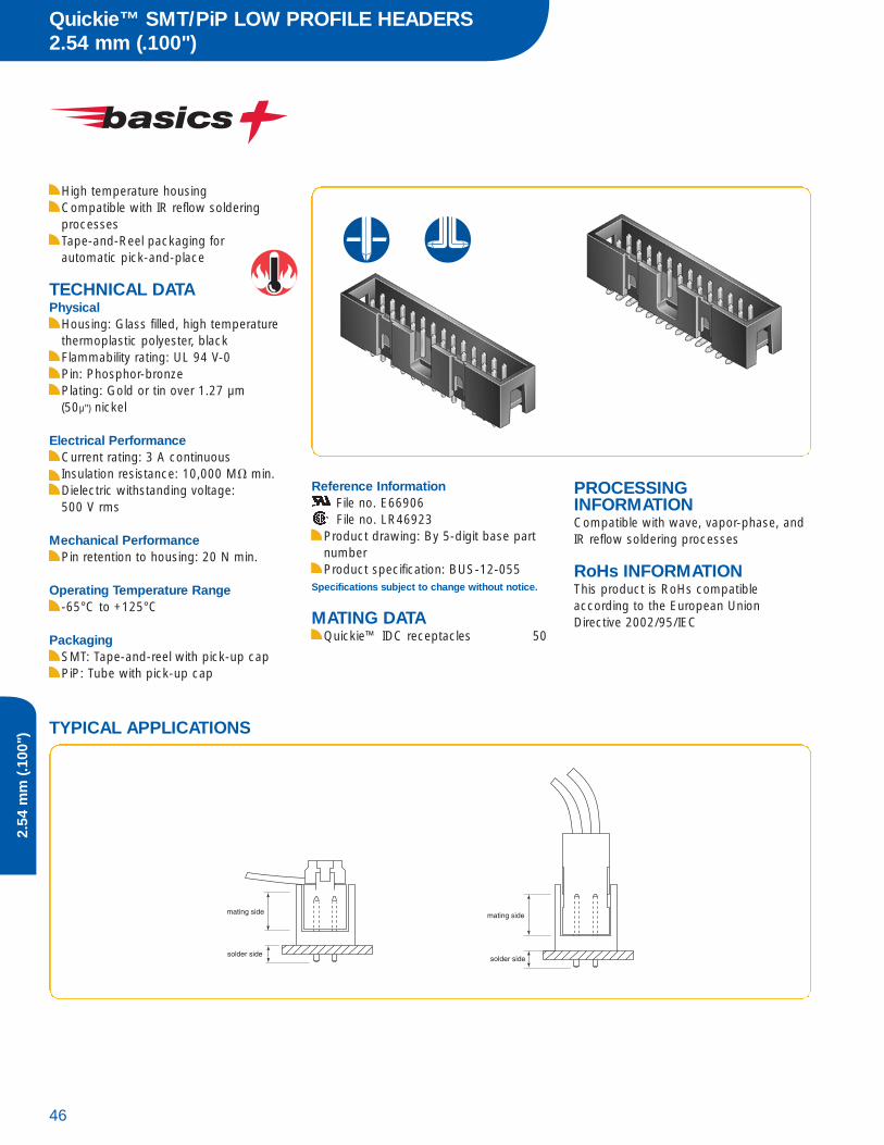
High temperature housingCompatible with IR reflow solderingprocessesTape-and-Reel packaging for automatic pick-and-place
TECHNICAL DATAPhysical
Housing: Glass filled, high temperaturethermoplastic polyester, blackFlammability rating: UL 94 V-0Pin: Phosphor-bronzePlating: Gold or tin over 1.27 µm (50µ") nickel
Electrical PerformanceCurrent rating: 3 A continuousInsulation resistance: 10,000 M� min. Dielectric withstanding voltage: 500 V rms
Mechanical PerformancePin retention to housing: 20 N min.
Operating Temperature Range-65°C to +125°C
PackagingSMT: Tape-and-reel with pick-up capPiP: Tube with pick-up cap
Reference InformationFile no. E66906File no. LR46923
Product drawing: By 5-digit base partnumberProduct specification: BUS-12-055
Specifications subject to change without notice.
MATING DATAQuickie™ IDC receptacles 50
TYPICAL APPLICATIONS
PROCESSING INFORMATIONCompatible with wave, vapor-phase, andIR reflow soldering processes
RoHs INFORMATIONThis product is RoHs compatible according to the European UnionDirective 2002/95/IEC

47Technical / Application Support / Drawings / Specifications / Samples: www.fciconnect.com/basics
2.54
mm
(.100
")
10056844
72454
72454 TotalPositions
08, 10, 14, 16, 20, 40
0 V LF
Base Part Number TotalPositions
08, 10, 14, 16, 20, 26, 30, 34, 40
1 LF
PART NUMBERSMT (Surface Mount)
PiP (Pin-in-Paste)
10056844 = Vertical10056845 = Right angle
Recommended PCB Layout

Quickie™ SHROUDED EJECT LATCH HEADERS2.54 mm (.100")
48
2.54
mm
(.100
")
Selective platingRecessed pins assure proper alignment and eliminate damage during mating
TECHNICAL DATAPhysical
Housing: Glass filled, thermoplastic polyester, greyFlammability rating: UL 94 V-0
Electrical PerformanceCurrent rating: 3 A continuousInsulation resistance: 10,000 M� minDielectric withstanding voltage:1500 V
Mechanical PerformancePin retention to housing: 20 N min.
Operating Temperature Range-65°C to +125°C
PackagingTubes
Reference InformationFile no. E66906File no. LR46923
Product drawing: By 5-digit base partnumberProduct specification: BUS-12-082
Specifications subject to change without notice.
MATING DATAQuickie™ IDC receptacles 50
PROCESSING INFORMATIONCompatible with wave soldering processes
RoHs INFORMATIONThis product is RoHs compatible according to the European UnionDirective 2002/95/IEC
LATCHING STYLES
Standard Latch (Style 1) Low profile Latch (Style 2)

49Technical / Application Support / Drawings / Specifications / Samples: www.fciconnect.com/basics
2.54
mm
(.100
")
PART NUMBER
06, 08, 10, 14, 16, 18, 20, 26,30, 34, 40, 44, 50, 60, 64
Latch Style
5-Digit Base Part Number TotalPositions
Through mount71918 = Vertical71922 = Right angle
Plating = 0.76 µm (30µ") gold on mating area, tin on solder side
1 = Standard (mates with IDCReceptacle Strain Relief 0,2
2 = Low Profile (mates with IDCReceptacle without Strain Relief
LF
71918 1XXLF
71922 1XXLF
XX = 04, 06, 08, 10, 12, 16, 20
71918 1XXLF
XX = 10 - 40
Dimensions in mm
71922 1XXLF
Recommended PCB Layout
Vertical
Right Angle
Quickie™ IDC RECEPTACLES2.54 mm (.100")
50
2.54
mm
(.100
")
TECHNICAL DATAPhysical
Housing: Grey thermoplasticFlammability rating: UL 94 V-0Contact: Phosphor-bronzePlating: 0.76 µm (30µ") Gold over 1.27 µm (50 µ") nickel
Electrical PerformanceCurrent rating: 1 A continuousInsulation resistance: 50,000 M� min.Contact resistance: 15 m� max. Dielectric withstanding voltage: 1000 V min. rms (sea level)
Mechanical PerformanceMating cycles (durability): 100
Operating Temperature Range-65°C to +125°C
PackagingTubes
Reference InformationFile no. E66906File no. LR46923
Product drawing: By 5-digit base partnumberProduct specification: BUS-12-095
Specifications subject to change without notice.
MATING DATABergStik® unshrouded vertical headers 10, 12, 14Quickie® shrouded low profile headers 44, 46Quickie® shrouded eject latch headers 48
RoHs INFORMATIONThis product is RoHs compatible according to the European UnionDirective 2002/95/IEC
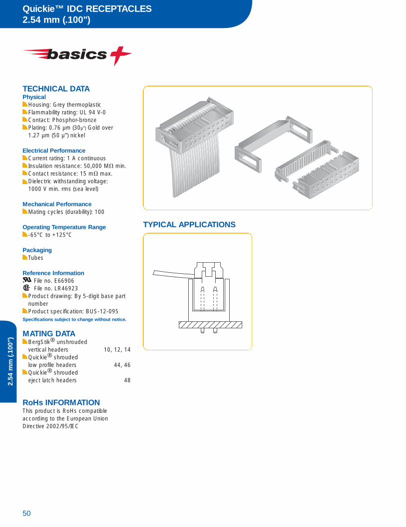
TYPICAL APPLICATIONS
51Technical / Application Support / Drawings / Specifications / Samples: www.fciconnect.com/basics
2.54
mm
(.100
")
PART NUMBER
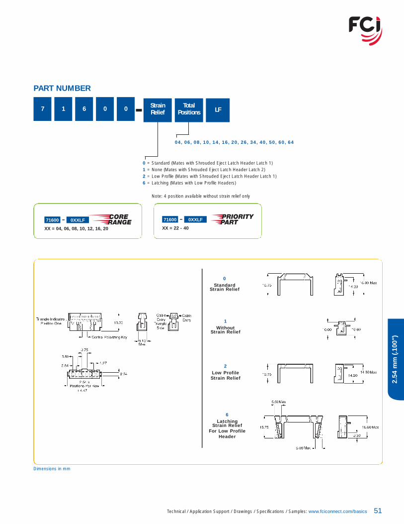
7 1 6 0 0 TotalPositions
04, 06, 08, 10, 14, 16, 20, 26, 34, 40, 50, 60, 64
StrainRelief
0 = Standard (Mates with Shrouded Eject Latch Header Latch 1)1 = None (Mates with Shrouded Eject Latch Header Latch 2)2 = Low Profile (Mates with Shrouded Eject Latch Header Latch 1)6 = Latching (Mates with Low Profile Headers)
Note: 4 position available without strain relief only
LF
71600 0XXLF
XX = 04, 06, 08, 10, 12, 16, 20
71600 0XXLF
XX = 22 - 40
1Without
Strain Relief
0Standard
Strain Relief
6Latching
Strain ReliefFor Low Profile
Header
2Low ProfileStrain Relief
Dimensions in mm

Quickie™ IDC 2-ROW PCB CONNECTORS2.54 mm (.100")
52
2.54
mm
(.100
")
Ideal for daisy chain applicationsSingle piece design provides one of the lowest applied costs in the industry
TECHNICAL DATAPhysical
Housing: Blue thermoplasticFlammability rating: UL 94 V-0Pin: Phosphor-bronzePlating: Tin over 1.27 µm (50µ") nickel
Electrical PerformanceCurrent rating: 1 A continuousInsulation resistance: 50,000 M� min.Contact resistance: 15 m� max. Dielectric withstanding voltage: 1000 V min.
Operating Temperature Range-65°C to +125°C
PackagingTubes
Reference InformationFile no. E66906File no. LR46923
Product drawing: By 5-digit base partnumberProduct specification: 110-019
Specifications subject to change without notice.
PROCESSING INFORMATIONCompatible with wave and vapor phasesoldering processes — Low temperature
RoHs INFORMATIONThis product is RoHs compatible according to the European UnionDirective 2002/95/IEC
53Technical / Application Support / Drawings / Specifications / Samples: www.fciconnect.com/basics
2.54
mm
(.100
")
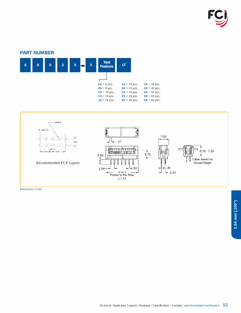
PART NUMBER
6 9 8 3 0 0Total
Positions
02 = 6 pos. 18 = 18 pos. 34 = 34 pos.08 = 8 pos. 20 = 20 pos. 40 = 40 pos.10 = 10 pos. 24 = 24 pos. 50 = 50 pos.14 = 14 pos. 26 = 26 pos. 60 = 60 pos.16 = 16 pos. 30 = 30 pos. 64 = 64 pos.
LF
Recommended PCB Layout
Dimensions in mm

Minitek™ UNSHROUDED VERTICAL HEADERS2.00 mm (.079")
54
2.00
mm
(.079
")
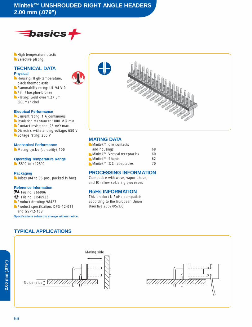
TECHNICAL DATAPhysical
Housing: High-temperature, black thermoplasticFlammability rating: UL 94 V-0Pin: Phosphor-bronzePlating: Gold over 1.27 µm (50 µ") nickel
Electrical PerformanceCurrent rating: 1 A continuousInsulation resistance: 1000 M� min.Contact resistance: 25 m� max.Dielectric withstanding voltage: 650 VVoltage rating: 200 V
Mechanical PerformanceMating cycles (durability): 100
Operating Temperature Range-55°C to +125°C
PackagingStandard: TMT in tubes (04 to 06 pos.packed in box)SMT in Tape-and-reelOptional: SMT in Tubes
Reference InformationFile no. E66906File no. LR46923
Product drawing: 57102 or 57202Product specification: DPS-12-011and GS-12-163 Tape and Reel packaging data: TA-884
Specifications subject to change without notice.
MATING DATAMinitek™ ctw contacts and housings 68Minitek™ Vertical receptacles 60Minitek™ Shunts 62Minitek™ IDC receptacles 70
PROCESSING INFORMATIONCompatible with wave, vapor-phase, and IR reflow soldering processes
RoHs INFORMATIONThis product is RoHs compatible according to the European UnionDirective 2002/95/IEC
Body
Solder side
Mating side
TYPICAL APPLICATIONS
55Technical / Application Support / Drawings / Specifications / Samples: www.fciconnect.com/basics
2.00
mm
(.079
")
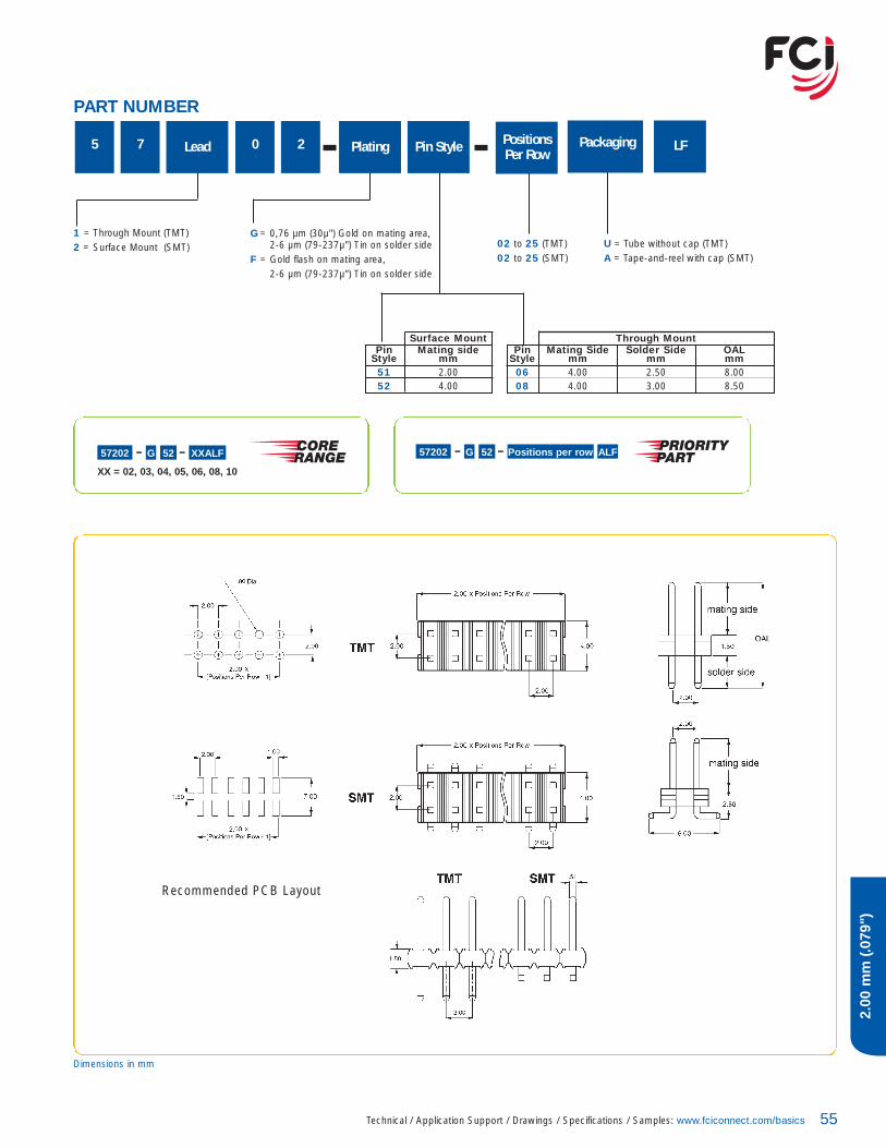
PART NUMBER
Dimensions in mm
1 = Through Mount (TMT)2 = Surface Mount (SMT)
G = 0,76 µm (30µ") Gold on mating area,2-6 µm (79-237µ") Tin on solder side
F = Gold flash on mating area,2-6 µm (79-237µ") Tin on solder side
5 7 0 2Lead Plating Pin Style
02 to 25 (TMT)02 to 25 (SMT)
PositionsPer Row
Surface MountPin Mating side
Style mm51 2.0052 4.00
Through MountPin Mating Side Solder Side OAL
Style mm mm mm06 4.00 2.50 8.0008 4.00 3.00 8.50
U = Tube without cap (TMT)A = Tape-and-reel with cap (SMT)
Packaging LF
Recommended PCB Layout
57202 G 52 XXALF
XX = 02, 03, 04, 05, 06, 08, 10
57202 G 52 Positions per row ALF
Minitek™ UNSHROUDED RIGHT ANGLE HEADERS2.00 mm (.079")
56
2.00
mm
(.079
")
High temperature plasticSelective plating
TECHNICAL DATAPhysical
Housing: High-temperature, black thermoplasticFlammability rating: UL 94 V-0Pin: Phosphor-bronzePlating: Gold over 1.27 µm (50µm) nickel
Electrical PerformanceCurrent rating: 1 A continuousInsulation resistance: 1000 M� min.Contact resistance: 25 m� max.Dielectric withstanding voltage: 650 VVoltage rating: 200 V
Mechanical PerformanceMating cycles (durability): 100
Operating Temperature Range-55°C to +125°C
PackagingTubes (04 to 06 pos. packed in box)
Reference InformationFile no. E66906File no. LR46923
Product drawing: 98423Product specification: DPS-12-011and GS-12-163
Specifications subject to change without notice.
MATING DATAMinitek™ ctw contacts and housings 68Minitek™ Vertical receptacles 60Minitek™ Shunts 62Minitek™ IDC receptacles 70
PROCESSING INFORMATIONCompatible with wave, vapor-phase, and IR reflow soldering processes
RoHs INFORMATIONThis product is RoHs compatible according to the European UnionDirective 2002/95/IEC
Solder side
Mating side
TYPICAL APPLICATIONS

57Technical / Application Support / Drawings / Specifications / Samples: www.fciconnect.com/basics
2.00
mm
(.079
")
9 8 4 2 3 Plating UPositionsPer Row
02 to 25G = 0,76 µm (30µ") Gold on mating area,2-6 µm (79-237µ") Tin on solder side
F = Gold flash on mating area,2-6 µm (79-237µ") Tin on solder side
61 LF
PART NUMBER
Dimensions in mm
Recommended PCB Layout
Minitek™ UNSHROUDED STACKING HEADERS2.00 mm (.079")
58
2.00
mm
(.079
")
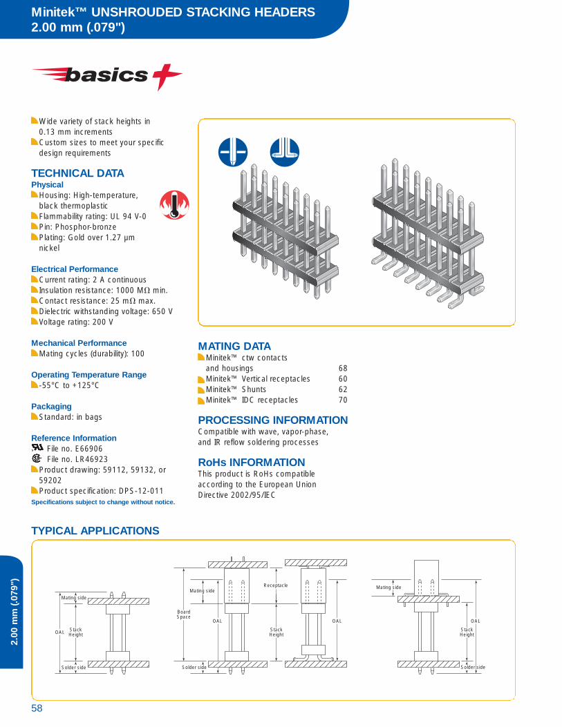
Wide variety of stack heights in 0.13 mm incrementsCustom sizes to meet your specificdesign requirements
TECHNICAL DATAPhysical
Housing: High-temperature, black thermoplasticFlammability rating: UL 94 V-0Pin: Phosphor-bronzePlating: Gold over 1.27 µm nickel
Electrical PerformanceCurrent rating: 2 A continuousInsulation resistance: 1000 M� min.Contact resistance: 25 m� max.Dielectric withstanding voltage: 650 VVoltage rating: 200 V
Mechanical PerformanceMating cycles (durability): 100
Operating Temperature Range-55°C to +125°C
PackagingStandard: in bags
Reference InformationFile no. E66906File no. LR46923
Product drawing: 59112, 59132, or59202Product specification: DPS-12-011
Specifications subject to change without notice.
MATING DATAMinitek™ ctw contacts and housings 68Minitek™ Vertical receptacles 60Minitek™ Shunts 62Minitek™ IDC receptacles 70
PROCESSING INFORMATIONCompatible with wave, vapor-phase, and IR reflow soldering processes
RoHs INFORMATIONThis product is RoHs compatible according to the European UnionDirective 2002/95/IEC
OAL
Mating side
OAL OAL
Receptacle
OAL
Solder side
StackHeight
BoardSpace
StackHeight
StackHeight
Mating side
Solder side
Mating side
Solder side
TYPICAL APPLICATIONS

59Technical / Application Support / Drawings / Specifications / Samples: www.fciconnect.com/basics
2.00
mm
(.079
")
1 = Through Mount (TMT)2 = Surface Mount (SMT)
02 to 25 (TMT)02 to 25 (SMT)
XXX = mmSpecify mm [i.e., 037 = 03.7 mm] in 0.1 mm increments
1 = 2.50 3 = 3.00 0 = SMT
5 9 2LeadSolderSide
Option Plating Pin Style Positions
Per RowStack Height
Pin OAL (TMT) OAL (SMT)Style mm mm22 8.20 6.5324 9.55 7.8726 10.19 8.5128 11.79 10.1130 13.54 11.8632 14.10 12.4234 15.60 13.9236 17.09 15.4238 19.08 17.4040 21.08 19.41
T = 0,76 µm (30µ") Gold on mating side, tin on solder side
LF
PART NUMBER
Dimensions in mm
Recommended PCB Layout
Step-by-Step Design1. Determine desired board spacing2. Select receptacle and calculate stack height
Stack Height = Board Spacing – Receptacle Height3. Find the insertion depth from the chart below.
Calculate max./min. OALOAL = Stack Height + Tail + Insertion Depth
4. Select the Pin Style with OAL between max. and min. values
Example:1. Application requires a board spacing of 12.5 mm2. Select the appropriate receptacle, in this case
4.5 mm height (SMT)The Header Stack Height is 12.5 - 4.5 = 8.0 mm
3. For 1,6 mm board application (TMT), the 2.5 Solder side is selectedOAL (max.) = 12.5 + 2.5 + 4.3 = 19.3OAL (min.) = 12.5 + 2.5 + 3.0 = 18.0
4. Select Pin Style 38 with OAL = 19.08 mm5. Part Number is 59112-G3810-080LF
RECEPTACLES
Height (mm) 4.50 2.30Insertion Depth (max.) 4.30 2.20 Insertion Depth (min.) 3.00 1.30
Minitek™ VERTICAL RECEPTACLES2.00 mm (.079")
60
2.00
mm
(.079
")
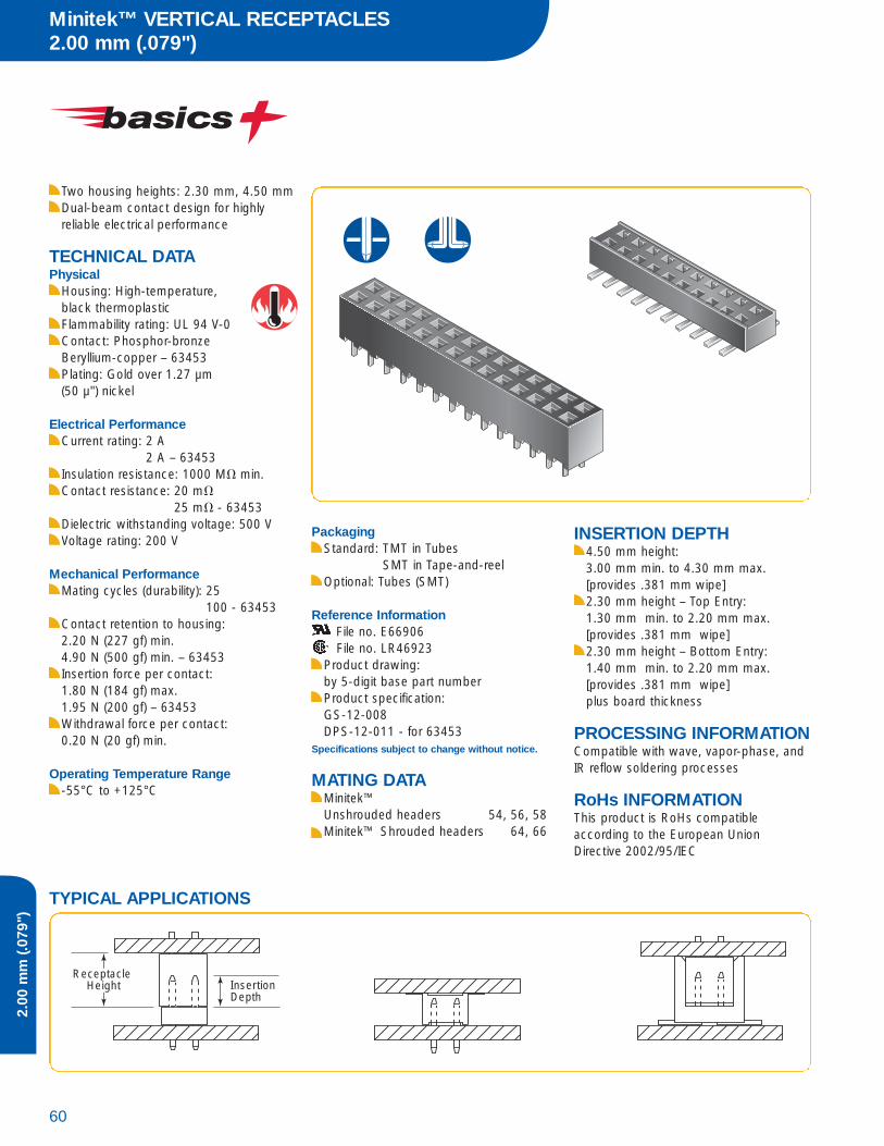
Two housing heights: 2.30 mm, 4.50 mmDual-beam contact design for highlyreliable electrical performance
TECHNICAL DATAPhysical
Housing: High-temperature, black thermoplasticFlammability rating: UL 94 V-0Contact: Phosphor-bronzeBeryllium-copper – 63453Plating: Gold over 1.27 µm (50 µ") nickel
Electrical PerformanceCurrent rating: 2 A
2 A – 63453Insulation resistance: 1000 M� min.Contact resistance: 20 m�
25 m� - 63453Dielectric withstanding voltage: 500 VVoltage rating: 200 V
Mechanical PerformanceMating cycles (durability): 25
100 - 63453Contact retention to housing: 2.20 N (227 gf) min.4.90 N (500 gf) min. – 63453Insertion force per contact: 1.80 N (184 gf) max.1.95 N (200 gf) – 63453Withdrawal force per contact: 0.20 N (20 gf) min.
Operating Temperature Range-55°C to +125°C
PackagingStandard: TMT in Tubes
SMT in Tape-and-reelOptional: Tubes (SMT)
Reference InformationFile no. E66906File no. LR46923
Product drawing: by 5-digit base part numberProduct specification: GS-12-008DPS-12-011 - for 63453
Specifications subject to change without notice.
MATING DATAMinitek™ Unshrouded headers 54, 56, 58Minitek™ Shrouded headers 64, 66
INSERTION DEPTH4.50 mm height: 3.00 mm min. to 4.30 mm max. [provides .381 mm wipe]2.30 mm height – Top Entry: 1.30 mm min. to 2.20 mm max. [provides .381 mm wipe]2.30 mm height – Bottom Entry: 1.40 mm min. to 2.20 mm max. [provides .381 mm wipe]plus board thickness
PROCESSING INFORMATIONCompatible with wave, vapor-phase, and IR reflow soldering processes
RoHs INFORMATIONThis product is RoHs compatible according to the European UnionDirective 2002/95/IEC
Receptacle Height Insertion
Depth
TYPICAL APPLICATIONS

61Technical / Application Support / Drawings / Specifications / Samples: www.fciconnect.com/basics
2.00
mm
(.079
")
PART NUMBER
5-Digit Base Part Number TotalPositions
04 to 50 Top Entry04 to 30 Bottom Entry
Plating
Through Mount (TMT)
Height Entry
63453 4.50 Top
Surface Mount (SMT)
55510 4.50 Top55508 2.30 Top91596 2.30 Bottom
Packaging
1 = 0,76 µm (30µ") Gold on mating area,2-6 µm (79-237µ") Tin on solder side
0 = Gold flash
- = Tubes (TMT)TR = Tape-and-reel (SMT)
LF
Dimensions in mm
55510 1XXTRLF
XX = 04, 06, 08, 10, 12, 16, 20
55510 1 Total Positions TRLF
Recommended PCB Layout
Bottom Entry
Top Entry
P/N 63453
P/N 55510
P/N 55508

Minitek™ SHUNTS2.00 mm (.079")
62
2.00
mm
(.079
")
Early entry, dual-beam contacts provide long wiping action for reliable electrical contact
TECHNICAL DATAPhysical
Housing: Black thermoplasticFlammability rating: UL 94 V-0Contact: Phosphor-bronzePlating: Gold or tin-lead over 1.27 µm(50 µ") nickel
Electrical PerformanceCurrent rating: 1 A continuousInsulation resistance: 1000 M� min.Contact resistance: 25 m� max.Dielectric withstanding voltage: 650 VVoltage rating: 200 V
Mechanical PerformanceMating cycles (durability): 50Insertion force per contact: 6.41 N (650 gf) max.Withdrawal force per contact: 0.49 N (50 gf) min.
Operating Temperature Range-40°C to +105°C
PackagingBags
Reference InformationFile no. E66906File no. LR46923
Product drawing: By 5-digit base partnumberProduct specification: DPS-12-012
Specifications subject to change without notice.
MATING DATAMinitek™ Unshrouded headers 54, 56, 58Minitek™ Shrouded headers 64, 66
INSERTION DEPTH2.24 mm min. [provides .381 mm wipe]
RoHs INFORMATIONThis product is RoHs compatible according to the European UnionDirective 2002/95/IEC
63Technical / Application Support / Drawings / Specifications / Samples: www.fciconnect.com/basics
2.00
mm
(.079
")
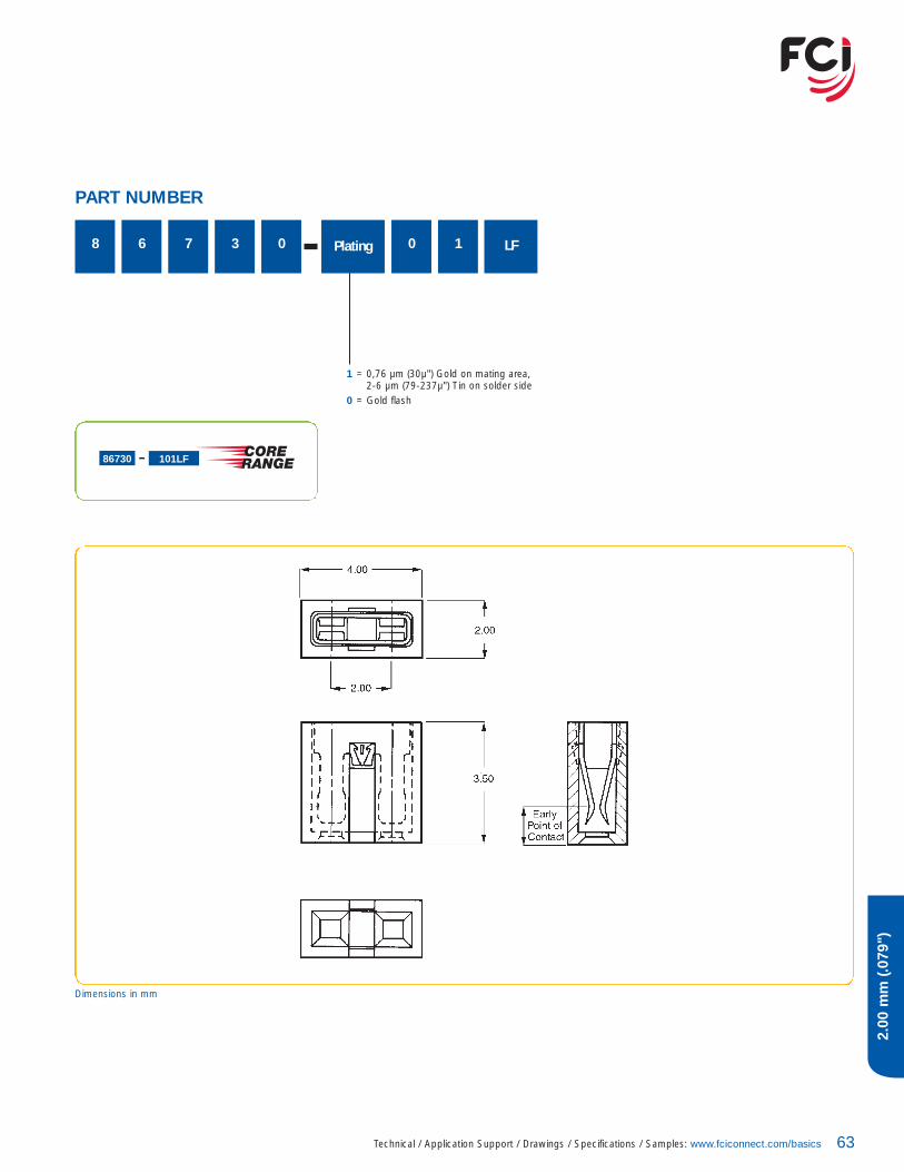
8 6 7 3 0 Plating 0 1
1 = 0,76 µm (30µ") Gold on mating area,2-6 µm (79-237µ") Tin on solder side
0 = Gold flash
LF
PART NUMBER
86730 101LF
Dimensions in mm

Minitek™ SHROUDED VERTICAL HEADERS2.00 mm (.079")
64
2.00
mm
(.079
")
4-wall design prevents mis-matingSelective platingCo-planarity 0.1 (SMT)
TECHNICAL DATAPhysical
Housing: High temperature, cream-colored thermoplasticFlammability rating: UL 94 V-0Pin: Phosphor-bronzePlating: Gold over 1.27 µm (50 µ") nickel
Electrical PerformanceCurrent rating: 2 A continuousInsulation resistance: 1000 M� min.Contact resistance: 25 m� max.Dielectric withstanding voltage: 650 VVoltage rating: 200 V
Mechanical PerformanceMating cycles (durability): 100
Operating Temperature Range-40°C to +125°C
PackagingStandard: TMT in Tubes (04 to 06 pos.
packed in box)SMT in Tape-and-reel
Optional: SMT in Tubes (04 and 06 in box)
Reference InformationFile no. E66906File no. LR46923
Product drawing: 98414 or 98424Product specification: DPS-12-011and GS-12-163Tape and Reel packaging data TA-884
Specifications subject to change without notice.
MATING DATAMinitek™ ctw contacts and housings 68Minitek™ Vertical receptacles 60Minitek™ Shunts 62Minitek™ IDC receptacles 70
PROCESSING INFORMATIONCompatible with wave, vapor-phase, and IR reflow soldering processes
RoHs INFORMATIONThis product is RoHs compatible according to the European UnionDirective 2002/95/IEC
TYPICAL APPLICATIONS

65Technical / Application Support / Drawings / Specifications / Samples: www.fciconnect.com/basics
2.00
mm
(.079
")
PART NUMBER
5-Digit Base Part Number TotalPositions
04 to 5098414 = Through Mount, Double Row98424 = Surface Mount, Double Row
Plating
U = Tube (TMT)A = Tape-and-reel (SMT)
Packaging
G = 0,76 µm (30µ") Gold on mating area,2-6 µm (79-237µ") Tin on solder side
F = Gold flash on mating area,2-6 µm (79-237µ") Tin on solder side
Surface MountPin Mating side
Style mm52 4.00
Pin style
Through MountPin Mating side Solder side
Style mm mm06 4.00 2.50
LF
98424 G 52 XX ALF
XX = 04, 06, 08, 10, 12, 16, 20
98424 G 52 Total Positions ALF
Dimensions in mm
Recommended PCB Layout
Recommended PCB Layout

Minitek™ SHROUDED RIGHT ANGLE HEADERS2.00 mm (.079")
66
2.00
mm
(.079
")
4-wall designprevents mis-matingSelective plating
TECHNICAL DATAPhysical
Housing: High-temperature, cream-colored thermoplasticFlammability rating: UL 94 V-0Pin: Phosphor-bronzePlating: Gold over 1.27 µm (50 µ") nickel
Electrical PerformanceCurrent rating: 2 A continuousInsulation resistance: 1000 M� min.Contact resistance: 25 m� max.Dielectric withstanding voltage: 650 VVoltage rating: 200 V
Mechanical PerformanceMating cycles (durability): 100
Operating Temperature Range-40°C to +125°C
PackagingStandard: Tubes (04 to 06 pos. packed in box)
Reference InformationFile no. E66906File no. LR46923
Product drawing: 98464Product specification: DPS-12-011and GS-12-163
Specifications subject to change without notice.
MATING DATAMinitek™ ctw contacts and housings 68Minitek™ Vertical receptacles 60Minitek™ Shunts 62Minitek™ IDC receptacles 70
PROCESSING INFORMATIONCompatible with wave, vapor-phase, and IR reflow soldering processes
RoHs INFORMATIONThis product is RoHs compatible according to the European UnionDirective 2002/95/IEC
TYPICAL APPLICATIONS

67Technical / Application Support / Drawings / Specifications / Samples: www.fciconnect.com/basics
2.00
mm
(.079
")
PART NUMBER
TotalPositions
04 to 50 (Double Row)
Plating
G = 0,76 µm (30µ") Gold on mating area,2-6 µm (79-237µ") Tin on solder side
F = Gold flash on mating area,2-6 µm (79-237µ") Tin on solder side
619 8 4 6 4 U LF
Dimensions in mm
Recommended PCB Layout

Minitek™ CRIMP-TO-WIRE CONTACTS AND HOUSINGS 2.00 mm (.079")
68
2.00
mm
(.079
")
Dual-beam contact design for highlyreliable electrical performanceLatching key assures proper alignmentand friction retention
TECHNICAL DATAPhysical
Housing: Black thermoplasticFlammability rating: UL 94 V-0Contact: Phosphor-bronzePlating: Gold over 1.27 µm (50 µ") nickel
Electrical PerformanceCurrent rating: 2 A continuousInsulation resistance: 1000 M� min.Contact resistance: 20 m� max.Dielectric withstanding voltage: 650 VVoltage rating: 200 V
Mechanical PerformanceMating cycles (durability): 100Contact retention to housing: 7.83 N (800 gf) min.Mating force per contact: 1.77 N (180 gf) max.Unmating force per contact: 0.20 N (20gf) min.
Operating Temperature Range-40°C to +105°C
PackagingReels – ContactsBags – Housings
Reference InformationFile no. E66906File no. LR46923
Product drawing: 77138 or 77139 – Contact69307, 90311– HousingProduct specification: 110-036Application specification: 100-006, TA-959
Specifications subject to change without notice.
MATING DATAMinitek™ Unshrouded headers 54, 56, 58Minitek™ Shrouded headers 64, 66
INSERTION DEPTH2.40 mm min. to 3.30 mm max. [provides .381 mm wipe]3.63 mm min. to 4.00 mm max. [provides .381 mm wipe in housing]
RoHs INFORMATIONThis product is RoHs compatible according to the European UnionDirective 2002/95/IEC
Insertion Depth
TYPICAL APPLICATIONS

69Technical / Application Support / Drawings / Specifications / Samples: www.fciconnect.com/basics
2.00
mm
(.079
")
PART NUMBER
77138 = 26 AWG to 30 AWG77139 = 32 AWG to 36 AWG
Plating5-Digit Base Part Number
Housings
5-Digit Base Part Number
69307 = Double Row90311 = Double Row with Center Key
TotalPositions
04 to 50 (Double Row)
0
0 1
1 = 0,76 µm (30µ") Gold on mating area,2-6 µm (79-237µ") Tin on solder side
0 = Gold flash
LF
LF
77138 101LF
90311 0XXLF
XX = 04, 06, 08, 10, 12, 16, 20
90311 0 Total Posiions LF
Dimensions in mm

Minitek™ IDC RECEPTACLES2.00 mm (.079")
70
2.00
mm
(.079
")
Early entry, single-beam contacts provide long wiping action for reliable electrical contactCenter key polarization and friction latchoptions
TECHNICAL DATAPhysical
Housing: Black thermoplasticFlammability rating: UL 94 V-0Contact: Phosphor-bronzePlating: Gold over 1.27 µm (50 µ") nickel
Electrical PerformanceCurrent rating: 1 A continuousInsulation resistance: 1000 M� min.Contact resistance: 30 m� max.Dielectric withstanding voltage: 650 V
Mechanical PerformanceMating cycles (durability): 100
Operating Temperature Range-40°C to +105°C
PackagingTubes
Reference InformationFile no. E66906File no. LR46923
Product drawing: 89947 or 89361Product specification: BUS-12-115
Specifications subject to change without notice.
MATING DATAMinitek™ Unshrouded headers 54, 56, 58Minitek™ Shrouded headers 64, 66
INSERTION DEPTH2.55 mm min. to 4.57 mm max. [provides .381 mm wipe]
RoHs INFORMATIONThis product is RoHs compatible according to the European UnionDirective 2002/95/IEC
TYPICAL APPLICATIONS
71Technical / Application Support / Drawings / Specifications / Samples: www.fciconnect.com/basics
2.00
mm
(.079
")
PART NUMBER
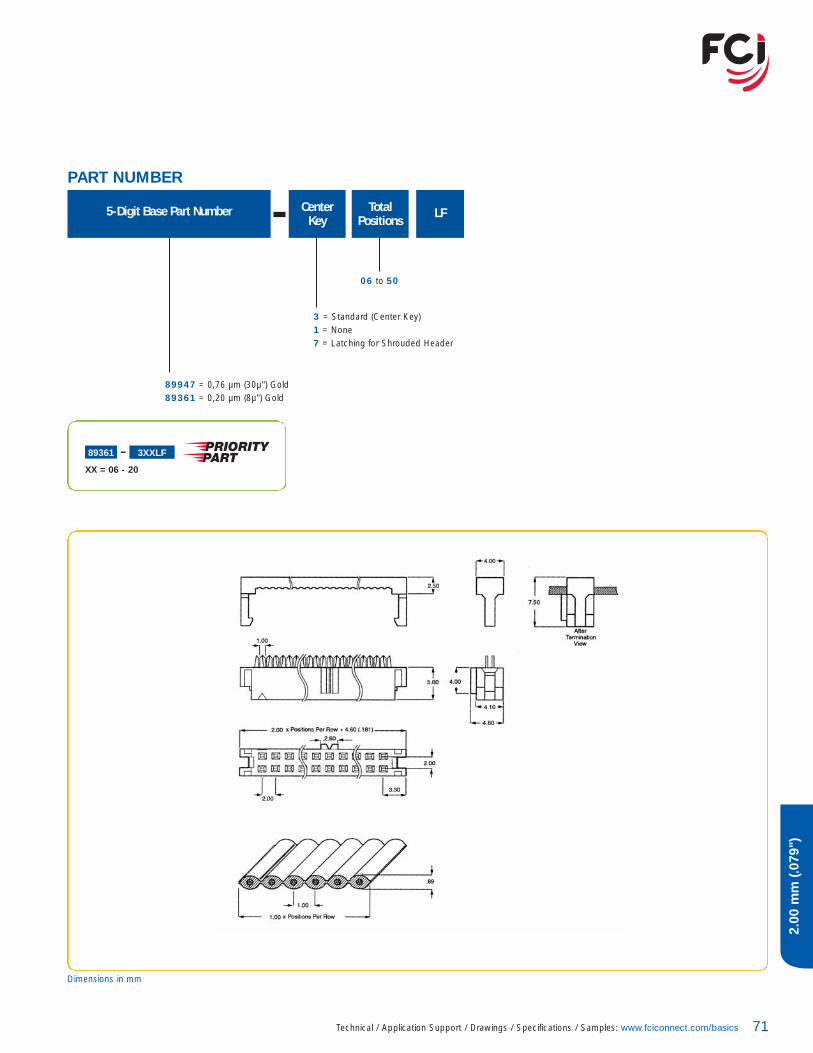
5-Digit Base Part Number TotalPositions
06 to 50
CenterKey
3 = Standard (Center Key)1 = None7 = Latching for Shrouded Header
89947 = 0,76 µm (30µ") Gold 89361 = 0,20 µm (8µ") Gold
LF
89361 3XXLF
XX = 06 - 20
Dimensions in mm

APPLICATION EQUIPMENT
72
DUBOX™ CONTACTHAND TOOL HT 234
Simple and reliableLow operation forceLightweight hand toolContains two toolings (AWG 22-24,AWG 26-30)
ORDERING DATAFor use with Dubox™ contacts, loose piecePart number 76357-x01 AWG 22-24/26-30 HT 234
ORDERING DATAFor use with Dubox™ contacts, on reelPart number 76347-x03 AWG 22-24 HT 250Part number 76347-x03 AWG 26-30 HT 251
Application rate/hour 500 (depending on operator dexterity)Weight 1 kgDimensions (h x w) 305 x 230 mm
HAND TOOL HT 250 / HT 251Simple and reliableLow operation forceLightweight hand toolReel fedSeperate toolings:HT 250 for AWG 22-24 HT 251 for AWG 26-30
For use with Dubox™ contacts, on reel
73Technical / Application Support / Drawings / Specifications / Samples: www.fciconnect.com/basics
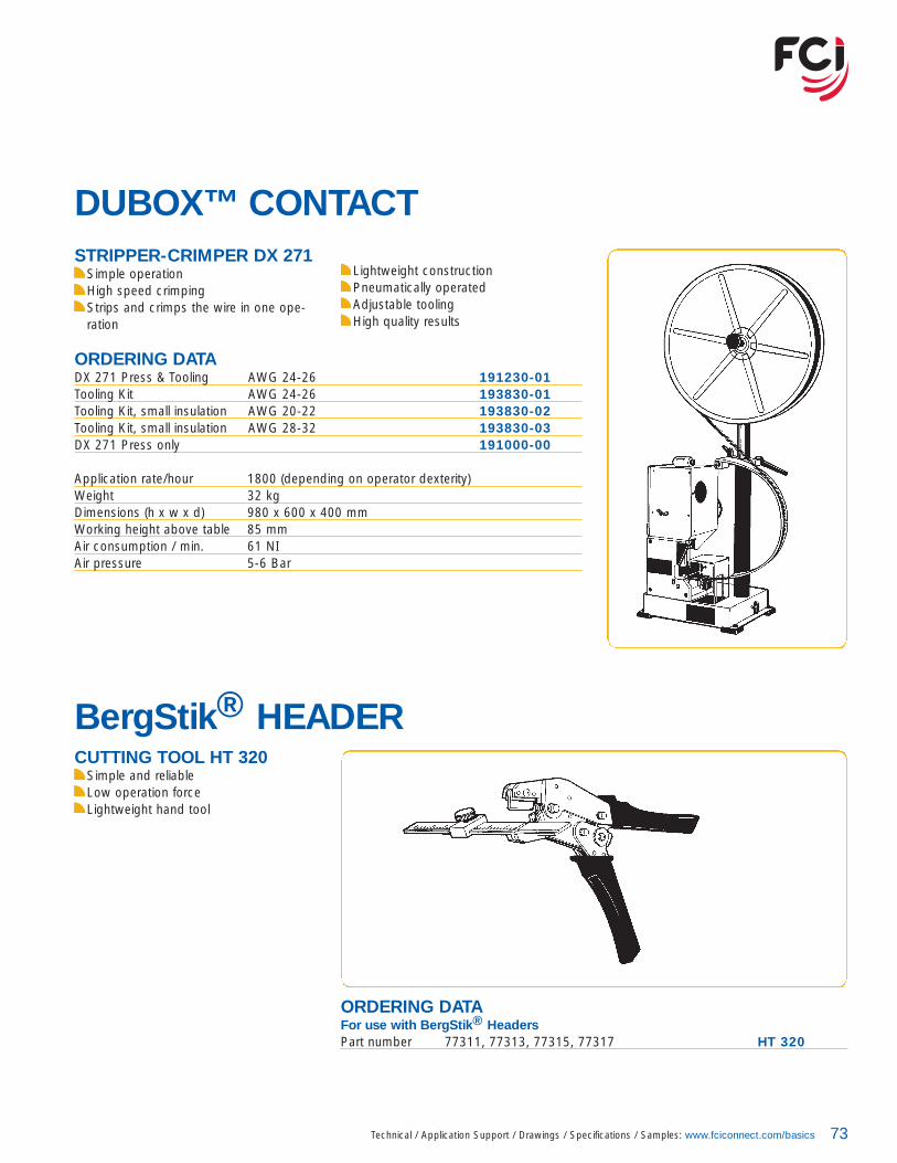
BergStik® HEADERCUTTING TOOL HT 320
Simple and reliableLow operation forceLightweight hand tool
ORDERING DATAFor use with BergStik® HeadersPart number 77311, 77313, 77315, 77317 HT 320
DUBOX™ CONTACTSTRIPPER-CRIMPER DX 271
Simple operationHigh speed crimpingStrips and crimps the wire in one ope-ration
Lightweight constructionPneumatically operatedAdjustable toolingHigh quality results
ORDERING DATADX 271 Press & Tooling AWG 24-26 191230-01Tooling Kit AWG 24-26 193830-01Tooling Kit, small insulation AWG 20-22 193830-02Tooling Kit, small insulation AWG 28-32 193830-03DX 271 Press only 191000-00
Application rate/hour 1800 (depending on operator dexterity)Weight 32 kgDimensions (h x w x d) 980 x 600 x 400 mmWorking height above table 85 mmAir consumption / min. 61 NIAir pressure 5-6 Bar

APPLICATION EQUIPMENT
74
MINITEK™ CONTACTSTRIPPER-CRIMPER MK 271
Simple and reliableHigh speed crimpingStrips and crimps the wire in one operation
ORDERING DATAMK 271 Press & Tooling AWG 26-30 193315-01Tooling Kit AWG 26-30 193317-01DX 271 Press only 193316-01
Application rate/hour 1500 (depending on operator dexterity)Weight 32 kgDimensions (h x w x d) 980 x 600 x 400 mmWorking height above table 85 mmAir consumption / min. 61 NIAir pressure 5-6 Bar
ORDERING DATAFor use with Dubox™ contacts, on reel
AWG 26-30 HT 151AWG 32-36 HT 152
Lightweight constructionPneumatically operatedAdjustable toolingHigh quality results
HAND TOOL HT 151 / HT 152Lightweight hand toolRuggedRatched-action handleassures complete crimp cycle

75Technical / Application Support / Drawings / Specifications / Samples: www.fciconnect.com/basics
DUBOX™ CONTACTSTRIPPER-CRIMPER DX 271
Simple operationReliablePneumatically operated
Low maintenance costHigh quality results
ORDERING DATAMK 411 Press & Tooling AWG 26-30 194294-01MK 411 Press & Tooling AWG 32-36 194294-02
Application rate/hour 1800 (depending on operator dexterity)Weight 25 kgDimensions (h x w x d) 710 x 560 x 400 mmWorking height above table 110 mmAir consumption / min. 28 NIAir pressure 5-6 BarElectrical requirements 220-240V, 50Hz, 0,5A
APPLICATION EQUIPMENT
76
PV™ CONTACTAPPLICATION TOOLING
PV™-250A Semi-automatic Crimping• Easy to use• Pneumatically operated• Low cost• Estimated 1000 crimps per hourMachine Part Number• 107416-101 (18-20AWG)• 107416-102 (22-26AWG)• 107416-103 (28-32AWG)
OL-740 Semi-automatic Two TonBench Press• Uses quick-changing, adjustable
crimping applicators for different terminals and wire sizes
• Most rugged construction• Easy to use• Electrically operated• Estimated 2400 crimps per hourMachine Part Number• 133911-102
(does not include applicator)Applicator Tooling Part Numbers• 133867-104 (18-20AWG)• 133867-105 (22-26AWG)• 133867-106 (28-32AWG)
Ratcheting Hand Crimping ToolPart Number• HT-0073 (for 18-20 AWG Wire)• HT-0096 (for 22-32 AWG Wire)• HT-0112 (for 32-36 AWG Wire)
PV™ Contact Removable ToolPart Number• HT-0080

77Technical / Application Support / Drawings / Specifications / Samples: www.fciconnect.com/basics
48045 4148046 4148047 4148048 4148049 4148050 4148051 4148052 4148231 4155508 6155510 6157102 5557202 5559112 5959132 5959202 5963429 2363453 6165039 4365043 4365239 3765240 3765846 4367996 13, 1567997 13, 1568000 13, 1568001 13, 1568002 13, 1568015 1968016 1968020 1968021 1968602 13, 1568786 2369145 2369167 3969168 3969307 6969830 5371600 5171607 3171609 3171918 4971920 2571922 4971991 27
72454 4775543 4175867 4575869 4575915 2576341 2776342 2776347 3576357 3576382 3376383 3376384 3376385 3377138 6977139 6977311 1177313 1177315 1777317 1778207 3978208 3978211 4386730 6387606 2589361 7189882 3189883 3189891 2589898 2989947 7190311 6991596 6191601 2991614 2991615 2991618 2995278 1195293 1198401 1198414 6598423 5798424 6598464 6710056844 4710056845 47
BASE PART NUMBER PAGE BASE PART NUMBER PAGE

NOTES
78


For more information about e-catalog or FCIsales offices, headquarters, agents and local distributors,
visit www.fciconnect.com
Americas - Phone: 1 (800) 237 2374 Europe - Phone: 33 1 39 49 21 83 Asia/Pacific- Phone: 65 6549 6666 Rea
lisat
ion:
En
Tout
e Tr
ansp
aren
ce