Conductivity Controller LRR 1-50 LRR 1-51 - GESTRA
32
EN English Original Installation & Operating Manual 819224-05 Conductivity Controller LRR 1-50 LRR 1-51
Transcript of Conductivity Controller LRR 1-50 LRR 1-51 - GESTRA

E NE n g l i s h
Original Installation & Operating Manual819224-05
Conductivity Controller
LRR 1-50LRR 1-51

2 LRR 1-50, LRR 1-51 - Installation & Operating Manual - 819224-05
ContentsPage
Important notes
Usage for the intended purpose ...............................................................................................................4Glossary ..................................................................................................................................................4Function ..................................................................................................................................................5Safety note ..............................................................................................................................................6
Directives and standards
EU Pressure Equipment Directive 2014/68/EU .........................................................................................7VdTÜV Bulletin “Wasserüberwachung 100” (Water Monitoring 100) .........................................................7LVD (Low Voltage Directive) and EMC (Electromagnetic Compatibility) .....................................................7ATEX (Atmosphère Explosible) .................................................................................................................7Notes on the Declaration of Conformity/Manufacturer’s Declaration ..................................................7
Technical data
LRR 1-50, LRR 1-51 ...............................................................................................................................8LRR 1-50 only .........................................................................................................................................9LRR 1-51 only .........................................................................................................................................9LRR 1-50, LRR -51 ..................................................................................................................................9Product package .....................................................................................................................................9Name plate/identification ......................................................................................................................10
Installation
Installation in the door of the control cabinet .........................................................................................11Dimensions of the LRR 1-50, LRR 1-51 .................................................................................................12Key .......................................................................................................................................................12Installation in a control cabinet ..............................................................................................................12
In the control cabinet: Wiring the conductivity controller
Wiring diagram for LRR 1-50 conductivity controller ..............................................................................13Key .......................................................................................................................................................13Wiring diagram for LRR 1-51 conductivity controller ..............................................................................14Key .......................................................................................................................................................14Supply voltage connection .....................................................................................................................15Connection of output contacts ...............................................................................................................15Connecting an LRG 12-2, LRG 16-4, LRG 17-1 or LRG 19-1 conductivity electrode and TRG 5-.. resistance thermometer ....................................................................................................15Connecting an LRG 16-9 conductivity electrode ....................................................................................15Wiring diagram for LRGT 1.-.. conductivity transmitter ..........................................................................16Connecting the actual value output ......................................................................................................16Tools .....................................................................................................................................................16

3LRR 1-50, LRR 1-51 - Installation & Operating Manual - 819224-05
ContentsPage
continued
In the system: Wiring the conductivity electrode/transmitter
Connecting an LRG 12-2, LRG 16-4, LRG 17-1 or LRG 19-1 conductivity electrode and TRG 5-.. resistance thermometer ....................................................................................................17Connecting an LRG 16-9 conductivity electrode ....................................................................................17Wiring diagram for LRGT 1.-.. conductivity transmitter ..........................................................................17
Factory settings ..................................................................................................................................18
Changing the factory settings
Conductivity controller LRR 1-50, LRR 1-51 .........................................................................................19Tools .....................................................................................................................................................19
Operating the conductivity controller
Meaning of codes on the 7-segment display .........................................................................................20
Bringing into service
Setting parameters................................................................................................................................21LRR 1-50 conductivity controller: Setting switchpoints and parameters ........................................... 22-23LRR 1-51 conductivity controller: Setting switchpoints and parameters .................................................24
Operation, alarm and testing
Conductivity controllers LRR 1-50, LRR 1-51: Checking the displays and the function of the MAXoutput contact .......................................................................................................................................25Password protection ..............................................................................................................................26
Troubleshooting
Indications, diagnosis and remedies ......................................................................................................27
Further information
Action against high-frequency interference ...........................................................................................28Replacing/taking the equipment out of service ......................................................................................28Disposal ................................................................................................................................................28

4 LRR 1-50, LRR 1-51 - Installation & Operating Manual - 819224-05
Important notes
Usage for the intended purpose
The LRR 1-50, LRR 1-51 conductivity controller is used in combination with the LRG 1.-.. conductivity electrodes and the LRGT 1.-.. conductivity transmitter as a conductivity controller and limit switch, e.g. in steam boilers and hot water installations and in condensate and feedwater tanks. The conductivity con-troller indicates when MAX conductivity is reached and opens or closes a continuous blowdown valve.Conductivity controllers can be combined in a circuit with conductivity electrodes or transmitters as follows: LRR 1-50 conductivity controller with LRG 12-2, LRG 16-4, LRG 16-9, LRG 17-1 and LRG 19-1 conductivity electrodes; LRR 1-51 conductivity controller with LRGT 16-1, LRGT 16-2, LRGT 16-3, LRGT 16-4, LRGT 17-3 and LRGT 17-1 conductivity transmitters.
Continuous blowdownAs the boiler water begins to evaporate, the concentration of non-volatile total dissolved solids (TDS) left behind in the boiler increases over time as a function of steam consumption. If the TDS concentra-tion exceeds the limit defined by the boiler manufacturer, foaming and priming occurs as the density of the boiler water increases, resulting in a carry-over of solids with vapour into steam lines and super-heaters. The consequences are adverse effects on reliability and severe damage to steam generating units and pipes. To keep the TDS concentration within admissible limits, a certain portion of boiler water must be removed continuously or periodically (by means of a continuous blowdown valve) and fresh feedwater must be added to the boiler feed to compensate for the water lost through blowdown. To determine the TDS in the boiler water, its electrical conductivity is measured in μS/cm, although some countries also use ppm (parts per million) as the unit of measurement. Conversion 1 µS/cm = 0.5 ppm.Operating position of the continuous blowdown valveIt is common practice to use the continuous blowdown valve to remove a certain amount of water from the boiler to keep the TDS within the desired limits. This means that the valve must be slightly open during operation, so that this water can be discharged (valve in OPERATING position). This operating position can be set on the continuous blowdown valve, and the amount of boiler blowdown can be established with the aid of the valve capacity charts.Switching hysteresisThe controller works as a 2-position controller, which means that the continuous blowdown valve is moved into OPEN position when the set point is reached. The conductivity must then decrease. Once it has fallen to a level that is lower than the set point minus the defined hysteresis, the valve is moved into OPERATING position.Temperature compensationThe electrical conductivity of water changes as the temperature falls or rises. To obtain meaningful readings, it is therefore necessary to base the measurements on the reference temperature of 25 °C, and to correct the measured conductivity using the temperature coefficient tC.Cell constant and correction factorThe geometric variable (cell constant) of the conductivity electrode is taken into account when calculating the conductivity. However, this constant may change during operation, e.g. due to dirt deposits on the measuring electrode. Deviations can be compensated by changing the correction factor CF.Flushing the continuous blowdown valveThe continuous blowdown valve can be flushed automatically to prevent it from sticking. In this case, the continuous blowdown valve is actuated at intervals (flushing interval Si) and opened for a certain time (flushing time Sd). After the flushing time, the valve is moved into the OPERATING position or into the required control position.
Glossary

5LRR 1-50, LRR 1-51 - Installation & Operating Manual - 819224-05
Important notes
Function
In combination with the LRG 1.-.. conductivity electrode, the LRR 1-50 conductivity controller meas-ures the electrical conductivity of conductive fluids. The LRG 1.-.. conductivity electrode or the LRG 16-9 electrode with integrated resistance thermometer is connected for measuring the fluid temperature. A separate Pt100 resistance thermometer may also be used to measure the temperature.The LRR 1-51 conductivity controller processes the current signal from the LRGT 1.-.. conductivity transmitter, which varies depending on the conductivity. This signal is normalised in the conductivity controller as a function of the adjusted measuring range and shown as an actual value on the 7-segment LED display.LRR 1-50 conductivity controller: When the LRG 1.-.. conductivity electrode is connected, a refer-ence measurement is taken and the conductivity reading is then adapted to the installation conditions by adjusting correction factor CF. If a resistance thermometer is connected, the water temperature is measured as well as the conductiv-ity. The conductivity reading is then automatically compensated in the conductivity controller based on the adjusted temperature coefficient tC (%/°C). If the temperature changes, thanks to linear tempera-ture compensation the reading is referenced to 25 °C across the entire measurement range, and shown as an actual value on the 7-segment LED display. The LRR 1-50, LRR 1-51 conductivity controller works as a 2-position controller, i.e. the continuous blowdown valve is moved into OPEN position when the set point is reached. After the conductivity has fallen by the set hysteresis, the valve returns to OPERATING position. To avoid loss of boiler water, the controller will automatically close the valve when the boiler is shut down. Two flashing LEDs indicate whether the continuous blowdown valve is opening or closing.The MAX limit can be adjusted as long as it remains within the measuring range. If the MAX limit is reached, the MAX output contact switches and the MAX LED lights up. It switches back when the conductivity has fallen below the set hysteresis. Faults or malfunctions in the conductivity electrode or conductivity transmitter, the electrical connection or the settings are indicated as error codes on the 7-segment LED display. In the event of a malfunction, the MAX alarm is triggered and the continuous blowdown valve moves into OPERATING position.If malfunctions occur only in the LRR 1-50, LRR 1-51 conductivity controller, the MAX alarm is trig-gered, the continuous blowdown valve moves into OPERATING position and the equipment is restarted.Parameters can be changed or the MAX alarm simulated using the rotary knob. Electrical conductivity is measured in µS/cm. In some countries, ppm (parts per million) is used instead. Conversion 1 µS/cm = 0.5 ppm. The conductivity controller can be set as appropriate.
continued

6 LRR 1-50, LRR 1-51 - Installation & Operating Manual - 819224-05
Safety note
The equipment may only be installed, wired and brought into service by qualified and competent staff.Maintenance and setup work may only be performed by authorised staff who have undergone specific training.
Danger
The terminal strips of the equipment are live during operation.There is a risk of serious injury due to electric shock!Always cut off power to the equipment before working on the terminal strips (installation, removal, connecting cables).
Attention
The name plate indicates the technical features of the equipment. Do not bring into ser-vice or operate any equipment that does not bear its own specific name plate.
Important notes continued

7LRR 1-50, LRR 1-51 - Installation & Operating Manual - 819224-05
Directives and standards
ATEX (Atmosphère Explosible)
The equipment must not be used in potentially explosive atmospheres, in accordance with European Directive 2014/34/EU.
LVD (Low Voltage Directive) and EMC (Electromagnetic Compatibility)
The equipment conforms to the requirements of the Low Voltage Directive 2014/35/EU and the EMC Directive 2014/30/EU.
Notes on the Declaration of Conformity/Manufacturer’s Declaration
For details on the conformity of our equipment with European Directives, please refer to our Declaration of Conformity or our Manufacturer's Declaration.The current Declaration of Conformity/Manufacturer's Declaration is available in Documents at www.gestra.com or can be requested from us.
Note
LRG 12-2, LRG 16-4, LRG 16-9, LRG 17-1 and LRG 19-1 conductivity electrodes are sim-ple items of electrical equipment as specified in EN 60079-11 section 5.7. According to European Directive 2014/34/EU, the equipment may be used in potentially explosive at-mospheres only in combination with approved Zener barriers. Suitable for use in Ex zones 1 and 2 (1999/92/EU). The equipment does not have Ex classification.
VdTÜV Bulletin “Wasserüberwachung 100” (Water Monitoring 100)
The LRR 1-50, LRR 1-51 conductivity controller, in combination with the LRG 1.-.. conductivity elec-trode and LRGT 1.-.. conductivity transmitter, has type approval in accordance with VdTÜV Bulletin “Wasserüberwachung 100”. The VdTÜV Bulletin “Wasserüberwachung 100” describes the require-ments for water monitoring equipment.
EU Pressure Equipment Directive 2014/68/EU
The LRG 1.-.., LRGT 1.-.., LRS 1-5.., LRR 1-5.. conductivity control and monitoring equipment satisfies the safety requirements of the EU Pressure Equipment Directive. The conductivity control and monitor-ing equipment has EC type approval in accordance with EN 12952/EN 12953. These Directives state, among other things, the requirements for limiting systems and equipment for steam boiler and hot water installations.

8 LRR 1-50, LRR 1-51 - Installation & Operating Manual - 819224-05
LRR 1-50, LRR 1-51
Supply voltage24 VDC +/– 20%FuseExternal semi-delay 0.5APower consumption4 WReset hysteresisMAX limit: –3% of set MAX limit, fixed.Outputs2 volt-free relay contacts, 8 A 250 V AC / 30 V DC cos ϕ = 1 (continuous blowdown valve OPEN, OPERATING, CLOSED). 1 volt-free relay contact, 8 A 250 V AC / 30 V DC cos ϕ = 1 (MAX alarm, switch-selectable).Inductive loads must have interference suppression (RC combination) as per the manufacturer's specification.1 analogue output 4-20 mA, max. output load 500 ohms, e.g. for actual value indication.Indicators and controls1 rotary knob with integrated pushbutton for testing the MAX alarm and setting parameters, 1 seven-segment, four-digit LED display, 1 red LED for MAX alarm, 2 amber LEDs for continuous blowdown valve opening/closing, 1 four-pole code switch for configuration.HousingHousing material: base of black polycarbonate; front of grey polycarbonate Conductor size: 1 x 4.0 mm2 solid per wire, or 1 x 2.5 mm2 per stranded wire with sleeve to DIN 46228 or 2 x 1.5 mm2 per stranded wire with sleeve to DIN 46228 (min. ∅ 0.1 mm) Terminal strips can be removed separately Housing attachment: Mounting clip on support rail TH 35, EN 60715Electrical safetyPollution degree 2 for installation in control cabinet with protection rating IP 54, fully insulatedIP rating Housing: IP 40 to EN 60529 Terminal strip: IP 20 to EN 60529 With panel adapter: IP 65 to EN 60529WeightApprox. 0.2 kg
Technical data

9LRR 1-50, LRR 1-51 - Installation & Operating Manual - 819224-05
LRR 1-50 only
Connecting a conductivity electrode1 input for LRG 1.-.. conductivity electrode (cell constant 1 cm-1), 3-pole with shield, or1 input for LRG 16-9 conductivity electrode (cell constant 0.5 cm-1), with integrated resistance ther-
mometer Pt100, 3-pole with shield.Measuring voltage0.8 Vss, pulse duty factor tv=0.5, frequency 20 – 10000 Hz.Measuring range1 to 10000 μS/cm at 25 °C or 1 to 5000 ppm at 25 °C.
Technical data
LRR 1-51 only
Connecting a conductivity transmitter1 analogue input 4-20 mA, e.g. for LRGT 1.-.. conductivity transmitter, 2-pole with shield.Lower end of measuring range SinL0 - 0.5 - 50 - 100 µS/cm, adjustable.Upper end of measuring range SinH20.0 - 100.0 - 200.0 - 500.0 -1000.0 - 2000.0 - 3000.0 - 5000.0 - 6000.0 - 7000.0 - 10000.0 - 12000.0 μS/cm, adjustable.
LRR 1-50, LRR -51
Ambient temperaturewhen system is switched on 0 ... 55 °C in operation –10 ... 55 °CTransport temperature–20 ... +80 °C (< 100 hours), only switch on after a defrosting period of 24 hours.Storage temperature–20 ... +70 °C, only switch on after a defrosting period of 24 hours.Relative humiditymax. 95%, non-condensingApprovals:TÜV Certificate VdTÜV Bulletin “Wasserüberwachung 100” (= Water Monitoring 100):
Requirements for water monitoring equipment Type approval number: TÜV · WÜL · XX-017
Product package
LRR 1-501 conductivity controller LRR 1-50 1 adhesive sign for ppm 1 Installation & Operating Manual
LRR 1-511 conductivity controller LRR 1-51 1 adhesive sign for ppm 1 Installation & Operating Manual
continued

10 LRR 1-50, LRR 1-51 - Installation & Operating Manual - 819224-05
IN 4-20
mA
LRG
T1.
.-..+_
OUT
4-20
mA
500 Ω
+_
M0,
5A4W
+1 2 3 4 6 7 8
TÜV.WÜL. -017XX
5
_24
V±
20%
0525
Absa
lzre
gler
Cont
inuo
us B
low
dow
nCo
ntro
ller
Régu
late
ur d
e dé
conc
en-
trat
ion
cont
inue
LR
R 1
-51
Betr
iebs
anle
itung
beac
hten
See
inst
alla
tion
inst
ruct
ions
Voir
inst
ruct
ions
dem
onta
ge
� � �
� L2
Tam
b =
55°C
(131
°F)
T
250V
~ T
2,5A
IP
(IP
20)
40
GE
ST
RA
AG
Mün
chen
er S
tr.7
728
215
Brem
enM
ade
in G
erm
any
Absa
lzre
gler
Cont
inuo
us B
low
dow
nCo
ntro
ller
Régu
late
ur d
e dé
conc
en-
trat
ion
cont
inue
LR
R 1
-50
Betr
iebs
anle
itung
beac
hten
See
inst
alla
tion
inst
ruct
ions
Voir
inst
ruct
ions
dem
onta
ge
� � �
� L2
250V
~ T
2,5A
IP
(IP
20)
40
Tam
b =
55°C
(131
°F)
T
GE
STR
A A
GM
ünch
ener
Str
.77
2821
5 Br
emen
Mad
e in
Ger
man
y
LRG
Pt10
0
1..-
..
1-50
00pp
m
1
-10
000µ
S/cm
+_
OUT
4-20
mA
500Ω
+_
M0,
5A4W
+1 2 3 4 6 7 85
TÜV.WÜL. -017XX
_24
V±
20%
0525
IP rating
Absa
lzre
gler
Cont
inuo
us B
low
dow
nCo
ntro
ller
Régu
late
ur d
e dé
conc
en-
trat
ion
cont
inue
LR
R 1
-50
Betr
iebs
anle
itung
beac
hten
See
inst
alla
tion
inst
ruct
ions
Voir
inst
ruct
ions
dem
onta
ge
� � �
� L2
250V
~ T
2,5A
IP
(IP
20)
40
Tam
b =
55°C
(131
°F)
T
GE
STR
A A
GM
ünch
ener
Str
.77
2821
5 Br
emen
Mad
e in
Ger
man
y
LRG
Pt10
0
1..-
..
1-50
00pp
m
1
-10
000µ
S/cm
+_
OUT
4-20
mA
500Ω
+_
M0,
5A4W
+1 2 3 4 6 7 85
TÜV.WÜL. -017XX
_24
V±
20%
0525
Technical data
Name plate/identification
Name plate of LRR 1-50, LRR 1-51, topSafety note
Output contacts
Ambient temperature
Type designation
Manufacturer
Fig. 1
Supply voltage
Fuse, provided on site
Power consumption
Disposal note
Connection of conductivity electrode
Type approval number
Measuring range
External fuse for output contacts
Name plate of LRR 1-50, bottom
Connection of actual value output
Supply voltage
Fuse, provided on site
Power consumption
Disposal note
Connection of conductivity transmitter
Type approval number
Name plate of LRR 1-51, bottom
Connection of actual value output
continued
11LRR 1-50, LRR 1-51 - Installation & Operating Manual - 819224-05
Installation
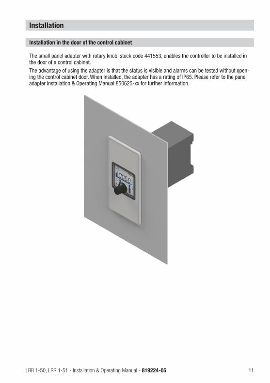
The small panel adapter with rotary knob, stock code 441553, enables the controller to be installed in the door of a control cabinet. The advantage of using the adapter is that the status is visible and alarms can be tested without open-ing the control cabinet door. When installed, the adapter has a rating of IP65. Please refer to the panel adapter Installation & Operating Manual 850625-xx for further information.
Installation in the door of the control cabinet

12 LRR 1-50, LRR 1-51 - Installation & Operating Manual - 819224-05
Installation
Dimensions of the LRR 1-50, LRR 1-51
Fig. 2
1 Upper terminal strip
2 Lower terminal strip
Key
Installation in a control cabinet
The LRR 1-50, LRR 1-51 conductivity controller is clipped onto a type TH 35, EN 60715 support rail in the control cabinet. Fig. 1 4
3 Housing
4 Support rail TH 35, EN 60715
4 3
1
2
46
74
120 15
continued

13LRR 1-50, LRR 1-51 - Installation & Operating Manual - 819224-05
In the control cabinet: Wiring the conductivity controller
Wiring diagram for LRR 1-50 conductivity controller
5 Connection of supply voltage 24 V DC with semi-delay fuse 0.5A provided on site
6 Actual value output 4-20 mA
7 LRG 1.-.. conductivity electrode (terminal 6/7: resistance thermometer can be connected)
8 Central earthing point (CEP) in control cabinet
Key
9 LRG 16-9 conductivity electrode with integrated resistance thermometer
0 MAX output contact
a Supply voltage L2
b Supply voltage N
OPERATINGOPEN CLOSED
Actuator EF
0.5A (semi- delay)
0.5A (semi- delay)
58
b
76
8
9
5
a
0
When the burner is switched off (standby) and therefore also the power supply to the control-ler, L2 must remain on until the actuator has closed the continuous blowdown valve.
Fig. 3
6

14 LRR 1-50, LRR 1-51 - Installation & Operating Manual - 819224-05
In the control cabinet: Wiring the conductivity controller
Wiring diagram for LRR 1-51 conductivity controller
5 Connection of supply voltage 24 V DC with semi-delay fuse 0.5A provided on site
6 Actual value output 4-20 mA
7 LRGT 1.-.. conductivity transmitter, 4-20 mA, with earthing point
8 Central earthing point (CEP) in control cabinet
Key
0 MAX output contact
a Supply voltage L2
b Supply voltage N
OPERATING
OPEN CLOSED
Actuator EF
0.5A (semi- delay)
8
b
5 76
a
0
Fig. 4
When the burner is switched off (standby) and therefore also the power supply to the control-ler, L2 must remain on until the actuator has closed the continuous blowdown valve.
continued

15LRR 1-50, LRR 1-51 - Installation & Operating Manual - 819224-05
Connecting an LRG 12-2, LRG 16-4, LRG 17-1 or LRG 19-1 conductivity electrode and TRG 5-.. resistance thermometer
To connect the equipment, please use a shielded, multi-core control cable with a minimum conductor size of 0.5 mm2, e.g. LiYCY 4 x 0.5 mm2. Wire the terminal strip as shown in the wiring diagram. Fig. 3 Connect the shield to the central earthing point (CEP) in the control cabinet.Route the connecting cable between items of equipment separately from power lines.
In the control cabinet: Wiring the conductivity controller
Supply voltage connection
The equipment is supplied with 24 V DC and has an external semi-delay 0.5A fuse. Please use a safety power supply unit with reliable electrical isolation. This power supply unit must provide a level of isolation from dangerous contact voltages that at least meets the requirements for double or reinforced insulation in accordance with one of the following standards: DIN EN 50178, DIN EN 61010-1, DIN EN 60730-1 or DIN EN 60950.
Connection of output contacts
Wire the upper terminal strip 1 (terminals 16-23) in line with the desired switching functions. Provide an external slow-blow 2.5A fuse for the output contacts. Switching off inductive loads produces surges that can have a major adverse effect on the operation of open and closed-loop control systems. Connected inductive loads must therefore have interference suppression (RC combination) as per the manufacturer's specifications. If used as a conductivity limiter, the LRR 1-50, LRR 1-51 conductivity controller does not interlock auto-matically when the MAX limit is exceeded.If the installation requires a lockout function, this must be implemented in the downstream (safety) circuit. This circuit must conform to the requirements of EN 50156.
The LRG 16-9 conductivity electrode features an M12 A-coded, 5-pole sensor connector, see pin as-signment in Fig. 3. A pre-wired control cable (with plug and socket) is available in various lengths as an accessory for connecting the equipment. To connect the LRR 1-50 conductivity controller, please remove the connector and wire the terminal strip as shown in the wiring diagram. Fig. 3.Connect the shield to the central earthing point (CEP) in the control cabinet.If you are not using the pre-wired control cable, use a 5-core shielded control cable as a connecting cable, e.g. LiYCY 5 x 0.5 mm2. In addition, connect a shielded socket to the control cable at the elec-trode end.Route the connecting cable between items of equipment separately from power lines.
Connecting an LRG 16-9 conductivity electrode
continued

16 LRR 1-50, LRR 1-51 - Installation & Operating Manual - 819224-05
Wiring diagram for LRGT 1.-.. conductivity transmitter
To connect the equipment, please use a shielded, multi-core control cable with a minimum conductor size of 0.5 mm2, e.g. LiYCY 4 x 0.5 mm2, maximum length 100 m. Wire the terminal strip as shown in the wiring diagram. Fig. 4 Connect the shield as shown in the wiring diagram.Route the connecting cable between items of equipment separately from power lines.
In the control cabinet: Wiring the conductivity controller
Connecting the actual value output
For connection, please use a shielded, multi-core control cable with a minimum conductor size of 0.5 mm2, e.g. LiYCY 2 x 0.5 mm2, maximum length 100 m.Please note the maximum output load of 500 ohms.Wire the terminal strip as shown in the wiring diagram. Fig. 3, 4 Connect the shield just once to the central earthing point (CEP) in the control cabinet.Route the connecting cable between items of equipment separately from power lines.Any item of equipment that you wish to connect to the terminals for the 4-20 mA actual value output (optional) must be certified to have at least double or reinforced insulation to DIN EN 50178 or DIN 61010-1 or DIN EN 60730-1 or DIN EN 60950 between the current loop and live parts of the equipment that are not supplied with safety extra-low voltage (SELV).
Attention
n Do not use unused terminals as support terminals.
Tools
n Screwdriver size 3.5 x 100 mm, fully insulated to VDE 0680-1.
continued

17LRR 1-50, LRR 1-51 - Installation & Operating Manual - 819224-05
Wiring diagram for LRGT 1.-.. conductivity transmitter
To connect the equipment, please use a shielded, multi-core control cable with a minimum conductor size of 0.5 mm2, e.g. LiYCY 4 x 0.5 mm2, maximum length 100 m. Wire the terminal strip as shown in the wiring diagram. Fig. 4 Connect the shield as shown in the wiring diagram.Route the connecting cable between items of equipment separately from power lines.
In the system: Wiring the conductivity electrode/transmitter
Connecting an LRG 12-2, LRG 16-4, LRG 17-1 or LRG 19-1 conductivity electrode and TRG 5-.. resistance thermometer
To connect the equipment, please use a shielded, multi-core control cable with a minimum conductor size of 0.5 mm2, e.g. LiYCY 4 x 0.5 mm2. Wire the terminal strip as shown in the wiring diagram. Fig. 3 Connect the shield to the central earthing point (CEP) in the control cabinet.The max. cable length between the conductivity electrode/resistance thermometer and conduc-tivity controller is 30 m, or max. 10 m with a conductivity of 1-10 μS/cm. Route the connecting cable between items of equipment separately from power lines.
The LRG 16-9 conductivity electrode features an M12 A-coded, 5-pole sensor connector, see pin as-signment in Fig. 3. A pre-wired control cable (with plug and socket) is available in various lengths as an accessory for connecting the equipment. This control cable is not UV-resistant and must be protected with a UV-resistant plastic tube or cable duct if the equipment is installed outdoors.To connect the LRR 1-50 conductivity controller, please remove the connector and wire the terminal strip as shown in the wiring diagram. Fig. 3Connect the shield to the central earthing point (CEP) in the control cabinet.If you are not using the pre-wired control cable, use a 5-core shielded control cable as a connecting cable, e.g. LiYCY 5 x 0.5 mm2. In addition, connect a shielded socket to the control cable at the elec-trode end.The max. cable length between the conductivity electrode and controller is 30 m, or max. 10 m with a conductivity of 1-10 μS/cm. Route the connecting cable between items of equipment separately from power lines.
Connecting an LRG 16-9 conductivity electrode
Attention
n Please start up the equipment as described in the Installation & Operating Manuals for the LRG 12-2, LRG 16-4, LRG 16-9, LRG 17-1, LRG 19-1, TRG 5-.. and LRGT 1.-..
n Route the connecting cable between items of equipment separately from power lines.n Check the shield connection to the central earthing point (CEP) in the control cabinet.n The conductivity transmitter must be connected to its own dedicated supply voltage.

18 LRR 1-50, LRR 1-51 - Installation & Operating Manual - 819224-05
Factory settings
Conductivity controller LRR 1-50n MAX switchpoint AL.Hi = 6000 μS/cmn Set point SP = 3000 μS/cmn Dead band: +/– 5% of set pointn Reset hysteresis:
Set point: –10% of set point MAX limit: –3% (fixed)
n Correction factor CF = 1 n Temperature compensation inP = NO (no)n Temperature coefficient tC = 2.1%/°C n Current output normalisation Sout =
6000 μS/cm n Flushing interval Si = 0 h n Flushing time Sd= 3 min (valve opens for
3 min then closes for 3 min)n Damping FiLt: oFFn Password PW: oFFn Code switch a :
S1=OFF, S2=ON, S3=OFF, S4=OFF
Conductivity controller LRR 1-51n MAX switchpoint AL.Hi = 6000 μS/cmn Set point SP = 3000 μS/cmn Dead band: +/– 5% of set pointn Reset hysteresis:
Set point: –10% of set point MAX limit: –3% (fixed)
n Lower end of measuring range Sin.L = 0.5 μS/cm
n Upper end of measuring range Sin.H = 6000 μS/cm
n Current output normalisation Sout = 6000 μS/cm
n Flushing interval Si = 0 h n Flushing time Sd= 3 min (valve opens for
3 min then closes for 3 min)n Damping FiLt: oFFn Password PW: oFFn Code switch a :
S1=OFF, S2=ON, S3=OFF, S4=OFF

19LRR 1-50, LRR 1-51 - Installation & Operating Manual - 819224-05
Changing the factory settings
The upper terminal strip of the equipment is live during operation.There is a risk of serious injury due to electric shock!Always cut off power to the equipment before working on the terminal strip (installation, removal, connecting cables).
Danger
Attention
Do not change the settings of switches S1 and S2 on code switch a!
Tools
n Screwdriver size 3.5 x 100 mm, fully insulated to VDE 0680-1.
Code switch D - sliding switch, white
Conductivity controller LRR 1-50, LRR 1-51
Code switch D
S1 S2 S3 * S4 Configuration
OFF Reserve (factory setting)
ON Reserve
OFF Reserve
ON Reserve (factory setting)
OFFTerminal 3/4 (Out 2) as actual value output (X) (factory setting) *
ON Terminal 3/4 (Out 2) as manipulated variable output (Yw) *
OFFElectrical conductivity measured in µS/cm (factory setting)
ON Electrical conductivity measured in ppm
* Controller software version 311178.13 or later

20 LRR 1-50, LRR 1-51 - Installation & Operating Manual - 819224-05
Operating the conductivity controller
Meaning of codes on the 7-segment display
Fig. 4
Code Meaning
Appears when rotary knob is turned clockwise:AL.Hi Alarm High MAX switchpoint, adjustable between 1 and 9999 μS/cmSP Set point Set point, adjustable between 1 and 9999 μS/cmHySt Hysteresis Reset hysteresis, adjustable between 1 and 25% of set pointFiLt Filter Filter is switched on/off (damping)
PWPassword on = password protection is enabled
oFF = password protection is disabledFactory setting 1902 (cannot be changed)
Appears in parameterization modequit Quit Input is not confirmeddone Done Input is confirmed
Appears in the event of malfunctionsE.001 Error Temperature sensor defective, temperature reading too lowE.002 Error Temperature sensor defective, temperature reading too highE.005 Error Acquired reading defective, reading too lowE.006 Error Acquired reading defective, reading too high
LRR 1-50 onlyCAL Electrode calibration Electrode calibration. Last reading is displayedCF Correction factor Adjustable between 0.05 and 5.000 in increments of 0.001inP Input Pt100 Temperature compensation YES (no)tC Temperature coefficient Tc 0.0 – 3.0% per °C, adjustable in increments of 0.1LRR 1-51 onlySin.L Lower end of measuring range, adjustable: 0 - 0.5 - 50 - 100 μS/cm
Sin.H Upper end of measuring range, adjustable: 20.0 - 100.0 - 200.0 - 500.0 -1000.0 - 2000.0 - 3000.0 - 5000.0 - 6000.0 - 7000.0 - 10000.0 - 12000 μS/cm
Sout Current output normalisation, adjustable between 1 and 9999 μS/cmSi Flushing interval, adjustable between 0 and 24 hours in increments of 1hSd Flushing time, adjustable between 1 and 4 minutes in increments of 1min.
tESt Test Output relays are tested
Rotary knob with integrated pushbutton
MAX LED red
54327-segment display
LED 1 valve opens
LED 2 valve closes

21LRR 1-50, LRR 1-51 - Installation & Operating Manual - 819224-05
Starting
Action Indication Function
Switch on the supply voltage.
7-segment display shows software/version System test, takes approx. 3 sec.
7-segment display shows actual value, LEDs light up. System switches to operating mode
Actual value < set point
1. LED 1 flashes to indicate valve opening, 2. LED 2 flashes to indicate valve closing.
Continuous blowdown valve opens for the dura-tion of Sd then goes into OPERATING position.
Actual value > set point
1. LED 1 flashes to indicate valve opening, 2. LED 2 flashes to indicate valve closing.
Continuous blowdown valve opens. After con-ductivity has fallen by the set hysteresis HySt, the valve moves into OPERATING position.
Setting parameters
Action 7-segment display Function
Turn rotary knob until desired parameter is shown
Display toggles between parameter and saved value. Selecting the parameter
Press and hold the push-button (on rotary knob) First digit (0000) flashes.
Parameterization mode active. First digit can be changed.
Turn rotary knob A new value is displayed. Turning clockwise increases the value, turning anti-clockwise reduces the value.
Briefly press the pushbut-ton. The number increas-es with each press
2nd, 3rd or 4th digit flashes. (from right to left)
2nd, 3rd or 4th digit can be changed using the rotary knob. Turning clockwise increases the value, turning anti-clockwise reduces the value.
If you do not take any further action:
quit is briefly displayed. After this, the display toggles between the parame-ter and the old value.
The parameter is automatically shown once more and your entry is not confirmed.
When your entries are complete: press and hold the pushbutton
done is displayed. After this, the dis-play toggles between the parameter and the new value.
Your entry is confirmed and the parameter is automatically shown once more.
Turn the rotary knob until the next parameter is shown. Or turn the rotary knob until the actual value is displayed. Or after 30s, the actual value is displayed automatically.
Bringing into service
Setting parameters
Fig. 4
Rotary knob with integrated pushbutton
MAX LED red
54327-segment display
LED 1 valve opens
LED 2 valve closes
If password protection is enabled, you must enter the password before you can change parameters. For the password, see page 26.

22 LRR 1-50, LRR 1-51 - Installation & Operating Manual - 819224-05
Bringing into service
LRR 1-50 conductivity controller: Setting switchpoints and parameters
Setting the MAX switchpoint
Action Function
Select parameter AL.Hi, enter and save the desired conductivity.
Set the MAX switchpoint between 1 and 9999 μS/cm or 1 and 5000 ppm.
Setting the set point
Select parameter SP, enter and save the desired con-ductivity.
Set the set point between 1 and 9999 μS/cm or 1 and 5000 ppm.
Setting the reset hysteresis
Select parameter HySt, enter and save the required value.
Set the reset hysteresis between 1 and 25% of the set point.
Conductivity electrode LRG 1.-.: Setting the correction factor
Select correction factor CF, enter and save the required value.
Once operating temperature is reached, measure the conductivity of a water sample (at 25°C). In increments, set the correction factor until the displayed actual value matches the reference reading. This adapts the conduc-tivity reading to the installation conditions or compen-sates for deviations during operation.
Conductivity electrode LRG 1.-.. with separate resistance thermometer and LRG 16-9
Switching on temperature compensation
Select setting inP and turn the rotary knob clockwise. YES is displayed. Save the setting.
Setting the temperature coefficient
Select temperature coefficient tC, enter and save the desired percentage.
Once operating temperature is reached, measure the conductivity of a water sample (at 25°C). In increments, set the temperature coefficient until the displayed actual value matches the reference reading.
If necessary:Select correction factor CF, enter and save the required value. Alternatively, use calibration function CAL (software version “S-13” and later).
During operation, the indicated conductivity may differ from the reference reading, e.g. due to soiling. In that case, set the correction factor in increments until the displayed actual value matches the reference reading.
Normalising the current output
Select parameter Sout, enter and save the desired conductivity.
Set the current output between 1 and 9999 μS/cm
Setting the flushing interval and flushing time
Select parameter Si, enter and save the desired time. Set the flushing interval between 0 and 24 hours.
Select parameter Sd, enter and save the desired time. Set the flushing time between 1 and 4 minutes.
continued

23LRR 1-50, LRR 1-51 - Installation & Operating Manual - 819224-05
Calibration
Action Display FunctionTurn the rotary knob until the entry CAL is shown.
CAL is displayed. Calibration is selected.
Press and hold the pushbutton (on rotary knob)
The last reading is displayed and the digit on the right flashes (xxxX).
Enter the conductivity starting with the digit on the right.
Turn the rotary knob clock- wise or anti-clockwise to enter the required digit.
xxxX The first digit is entered.
Briefly press the pushbutton.Second digit from the right flashes (xxXx).
The second digit can be entered.
Repeat the last two steps to enter the conductivity in full.
The entered conductivity is displayed (xxxx).
The conductivity is entered in full.
quitProcessing time has elapsed. System switches back to the parameter. Entry was discontinued due to lack of activity.
Press and hold the pushbutton (on rotary knob).
donE New calibration value has been accepted and a corresponding CF value calculated.
PF.ErCF value is outside the admissible range. Previous calibration has been retained.
Bringing into service
LRR 1-50 conductivity controller: Setting switchpoints and parameters
continued
continued
24 LRR 1-50, LRR 1-51 - Installation & Operating Manual - 819224-05
Bringing into service
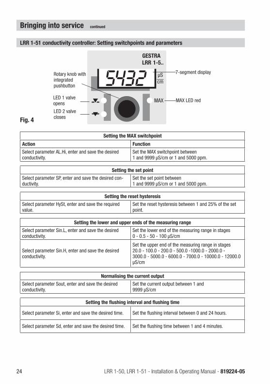
LRR 1-51 conductivity controller: Setting switchpoints and parameters
Setting the MAX switchpoint
Action Function
Select parameter AL.Hi, enter and save the desired conductivity.
Set the MAX switchpoint between 1 and 9999 μS/cm or 1 and 5000 ppm.
Setting the set point
Select parameter SP, enter and save the desired con-ductivity.
Set the set point between 1 and 9999 μS/cm or 1 and 5000 ppm.
Setting the reset hysteresis
Select parameter HySt, enter and save the required value.
Set the reset hysteresis between 1 and 25% of the set point.
Setting the lower and upper ends of the measuring range
Select parameter Sin.L, enter and save the desired conductivity.
Set the lower end of the measuring range in stages 0 - 0.5 - 50 - 100 μS/cm
Select parameter Sin.H, enter and save the desired conductivity.
Set the upper end of the measuring range in stages 20.0 - 100.0 - 200.0 - 500.0 -1000.0 - 2000.0 - 3000.0 - 5000.0 - 6000.0 - 7000.0 - 10000.0 - 12000.0 μS/cm
Normalising the current output
Select parameter Sout, enter and save the desired conductivity.
Set the current output between 1 and 9999 μS/cm
Setting the flushing interval and flushing time
Select parameter Si, enter and save the desired time. Set the flushing interval between 0 and 24 hours.
Select parameter Sd, enter and save the desired time. Set the flushing time between 1 and 4 minutes.
Fig. 4
Rotary knob with integrated pushbutton
MAX LED red
54327-segment display
LED 1 valve opens
LED 2 valve closes
continued
25LRR 1-50, LRR 1-51 - Installation & Operating Manual - 819224-05
Operation, alarm and testing
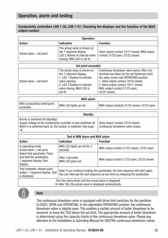
Conductivity controllers LRR 1-50, LRR 1-51: Checking the displays and the function of the MAX output contact
Operation
Action Indication Function
Actual value < set point
The actual value is shown on the 7-segment display. LED 2 flashes to indicate valve closing, MAX LED is not lit.
Valve output contact 19/17 closed, MAX output contact 21/23 open, 22/23 closed.
Test of MIN alarm and MAX alarm
Action Indication Function
In operating mode: Actual value < set point. Select Test parameter. Press and hold the pushbutton. 7-segment display: Test flashes.
MAX LED lights up red for 3 seconds MAX output contact 21/23 closed, 22/23 open.
After 3 seconds: MAX LED goes out. MAX output contact 21/23 open, 22/23 closed.
Test complete, release push-button. 7-segment display: Test is displayed.
Note: If you continue holding the pushbutton, the test sequence will start again. You can interrupt the test sequence at any time by releasing the pushbutton.
Turn the rotary knob until the actual value is displayed. Or after 30s, the actual value is displayed automatically.
Note
The continuous blowdown valve is equipped with three limit switches for the positions CLOSED, OPEN and OPERATING. In the adjustable OPERATING position, the continuous blowdown valve is slightly open. This enables a certain amount of boiler blowdown to be removed, to keep the TDS below the set limit. The appropriate amount of boiler blowdown is determined using the capacity charts of the continuous blowdown valve. Please pay attention to the Installation & Operating Manual for GESTRA continuous blowdown valves.
Set point exceeded
Actual value > set point
The actual value is shown on the 7-segment display. 1. LED 1 flashes to indicate valve opening, 2. LED 2 flashes to indicate valve closing. MAX LED is not lit.
Continuous blowdown valve opens. After con-ductivity has fallen by the set hysteresis HySt, the valve moves into OPERATING position. 1. Valve output contact 19/16 closed, 2. Valve output contact 19/17 closed. MAX output contact 21/23 open, 22/23 closed.
MAX alarmMAX conductivity switchpoint exceeded. MAX LED lights up red MAX output contacts 21/23 closed, 22/23 open.
Standby
Burner is switched off (standby) Supply voltage to the conductivity controller is also switched off. When it is switched back on, the system is restarted. See page 18
Valve output contact 19/18 closed. Continuous blowdown valve closes.
26 LRR 1-50, LRR 1-51 - Installation & Operating Manual - 819224-05
Operation, alarm and testing
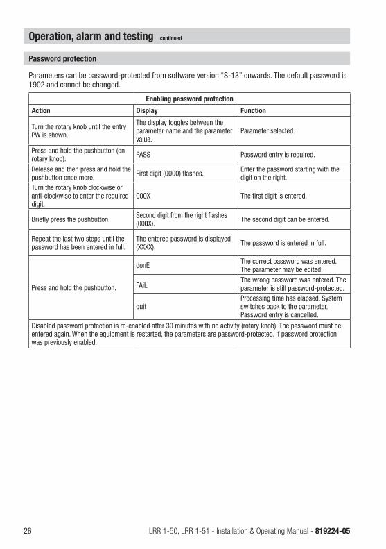
Enabling password protection
Action Display Function
Turn the rotary knob until the entry PW is shown.
The display toggles between the parameter name and the parameter value.
Parameter selected.
Press and hold the pushbutton (on rotary knob). PASS Password entry is required.
Release and then press and hold the pushbutton once more. First digit (0000) flashes. Enter the password starting with the
digit on the right.Turn the rotary knob clockwise or anti-clockwise to enter the required digit.
000X The first digit is entered.
Briefly press the pushbutton. Second digit from the right flashes (000X). The second digit can be entered.
Repeat the last two steps until the password has been entered in full.
The entered password is displayed (XXXX). The password is entered in full.
Press and hold the pushbutton.
donE The correct password was entered. The parameter may be edited.
FAiL The wrong password was entered. The parameter is still password-protected.
quitProcessing time has elapsed. System switches back to the parameter. Password entry is cancelled.
Disabled password protection is re-enabled after 30 minutes with no activity (rotary knob). The password must be entered again. When the equipment is restarted, the parameters are password-protected, if password protection was previously enabled.
Password protection
Parameters can be password-protected from software version “S-13” onwards. The default password is 1902 and cannot be changed.
continued

27LRR 1-50, LRR 1-51 - Installation & Operating Manual - 819224-05
Attention
Please check the following before fault diagnosis:Supply voltage:Is the conductivity controller supplied with the voltage specified on the name plate? WiringDoes the wiring conform to the wiring diagram?
Troubleshooting
Indications, diagnosis and remedies
Attention
n For further fault diagnosis, please refer to the Installation & Operating Manuals for the LRG 12-2, LRG 16-4, LRG 16-9, LRG 17-1, LRG 19-1, TRG 5-.. and LRGT 1.-..
Note
In the event of a malfunction in the conductivity controller, the MAX alarm is triggered and the equipment restarts. If the process is continually repeated, the equipment must be replaced.
Error codes on the 7-segment display
Error code Error Remedy
E.001 Temperature sensor defective, temperature reading too low Check resistance thermometer of LRG 16-9 conductiv-
ity electrode and replace if necessary. Check electrical connection (short circuit, open circuit?).E.002 Temperature sensor defective,
temperature reading too high
E.005
Conductivity electrode defective, reading too low.
Check conductivity electrode and replace if necessary. Check electrical connection.
Conductivity transmitter defective, measur-ing current < 4 mA
Check conductivity transmitter and replace if neces-sary. Check electrical connection.
E.006
Conductivity electrode defective, reading too high.
Check conductivity electrode and replace if necessary. Check electrical connection. Check boiler water.
Conductivity transmitter defective, measur-ing current > 20 mA
Check conductivity transmitter and replace if neces-sary. Check electrical connection.
E.097 Walkthrough application error Internal error. Replace equipment.
E.098 Walkthrough test error Internal error. Replace equipment.
E.099 Internal test error Internal error. Replace equipment.
In the event of a malfunction, the MAX alarm is triggered and the continuous blowdown valve moves into OPERATING position.
Error without a display
Error Remedy
Actual value < set point. Continuous blowdown valve opens. Check code switch S4. Switch must be in ON position.
All error codes not listed here are available as reserves.
28 LRR 1-50, LRR 1-51 - Installation & Operating Manual - 819224-05
Action against high-frequency interference
Further information
High-frequency interference can be caused by out-of-phase switching operations. If such interference occurs and results in sporadic failure, we recommend taking the following action to suppress interfer-ence:n Provide inductive loads with RC combinations as per manufacturer's specifications.n Route the connecting cable to the conductivity electrode or conductivity transmitter separately from
power lines.n Increase the distance from sources of interference. n Check the shield connection. Check the equipment shielding with the aid of the Installation & Oper-
ating Manuals. If equalisation currents can be expected (outdoor installations), connect the shield to one side only.
n Suppress HF interference using hinged-shell ferrite rings.
Disposal
The equipment must be disposed of in accordance with statutory waste disposal regulations.
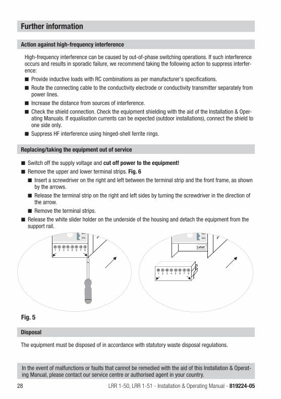
Fig. 5
Replacing/taking the equipment out of service
n Switch off the supply voltage and cut off power to the equipment! n Remove the upper and lower terminal strips. Fig. 6
n Insert a screwdriver on the right and left between the terminal strip and the front frame, as shown by the arrows.
n Release the terminal strip on the right and left sides by turning the screwdriver in the direction of the arrow.
n Remove the terminal strips.n Release the white slider holder on the underside of the housing and detach the equipment from the
support rail.
In the event of malfunctions or faults that cannot be remedied with the aid of this Installation & Operat-ing Manual, please contact our service centre or authorised agent in your country.

29LRR 1-50, LRR 1-51 - Installation & Operating Manual - 819224-05
For your notes
30 LRR 1-50, LRR 1-51 - Installation & Operating Manual - 819224-05
For your notes

31LRR 1-50, LRR 1-51 - Installation & Operating Manual - 819224-05
For your notes

819224-05/11-2021cm (808889-05) · GESTRA AG · Bremen · Printed in Germany
GESTRA AGMünchener Straße 77 28215 BremenGermanyTel. +49 421 3503-0 Fax +49 421 3503-393E-mail [email protected] www.gestra.com
You can find our authorised agents around the world at: www.gestra.com