Conducted by Geotech Specialists Ltd. Engineer: Finbarr ... · l 1 INTRODUCTION During May 2004,...
30
Conducted by Geotech Specialists Ltd. Engineer: Finbarr Gannon & Co. Ltd. REPORT NO [ KC4092 1 REPORT DATE 1 Aug 2004 REPORT ISSUE 1 Issue 1 NO 1 REPORT TITLE 1 Site at Youghal, Co. Cork / VOLUME NO and 11 NAME NO OF PAGES 115 / .,: . . For inspection purposes only. Consent of copyright owner required for any other use. EPA Export 25-07-2013:13:46:40
Transcript of Conducted by Geotech Specialists Ltd. Engineer: Finbarr ... · l 1 INTRODUCTION During May 2004,...
Conducted by Geotech Specialists Ltd.
Engineer: Finbarr Gannon & Co. Ltd.
REPORT NO [ KC4092
1 REPORT DATE 1 Aug 2004
REPORT ISSUE 1 Issue 1 NO 1
REPORT TITLE 1 Site at Youghal, Co. Cork /
VOLUME NO and 11 NAME NO OF PAGES 115
/
. , :
. .
For
insp
ectio
n pur
pose
s only
.
Conse
nt of
copy
right
owne
r req
uired
for a
ny ot
her u
se.
EPA Export 25-07-2013:13:46:40
l GCOTCCH
GEOTECH SPECIALISTS LIMITED Carewswood, Castlemartyr, Co. Cork, Ireland
Tel: (021) 4667164 Fax (021) 4667630 Email: [email protected]
Youg hal, Co. Cork
REPORT ON GROUND INVESTIGATION
Interpretative Report No. KC4092
Engineer: Finbarr Gannon & Co. Ltd
Engineer: Client:
Finbarr Gannon & Co. Ltd,
St Patrick’s House, sws Group,
Lower Glanmire Road, Shinagh House,
Bandon
For
insp
ectio
n pur
pose
s only
.
Conse
nt of
copy
right
owne
r req
uired
for a
ny ot
her u
se.
EPA Export 25-07-2013:13:46:40

CONTENTS
1 INTRODUCTION
2 THE SITE AND GEOLOGY 2.1 The Site 2.2 Published Geology
3 FIELDWORK 3.1 General 3.2 Exploratory Holes 3.3 Instrumentation and Monitoring 3.4 In Situ Testing
4 LABORATORY TESTING
5 GROUND CONDITIONS AND GROUNDWATER 5.1 Strata Encountered 5.2 Groundwater
6 GEOTECHNICAL ENGINEERING ASSESSMENT 6.1 Proposed Development 6.2 Foundations 6.3 Floor Slabs 6.4 Excavations and Groundwater 6.5 Infrastructure 6.6 Chemical Considerations for Buried Concrete
REFERENCES
l ENCLOSURES A EXPLORATORY HOLE RECORDS B INSTRUMENTATION MONITORING C GEOTECHNICAL LABORATORY TEST RESULTS D DRAWINGS
Page
1
1
2
3
4
5
8
For
insp
ectio
n pur
pose
s only
.
Conse
nt of
copy
right
owne
r req
uired
for a
ny ot
her u
se.
EPA Export 25-07-2013:13:46:40
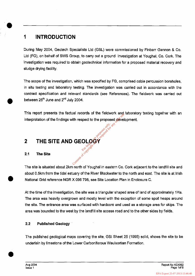
l 1 INTRODUCTION
During May 2004, Geotech Specialists Ltd (GSL) were commissioned by Finbarr Gannon & Co.
Ltd (FG), on behalf of SWS Group, to carry out a ground investigation at Youghal, Co. Cork. The
investigation was required to obtain geotechnical information for a proposed material recovery and
sludge drying facility.
The scope of the investigation, which was specified by FG, comprised cable percussion boreholes,
in situ testing and laboratory testing. The investigation was carried out in accordance with the
contract specification and relevant standards (see References). The fieldwork was carried out
l between 25’h June and 2”d July 2004.
This report presents the factual records of the fieldwork and laboratory testing together with an
interpretation of the findings with respect to the proposed development.
2 THE SITE AND GEOLOGY
2.1 The Site
The site is situated about 2km north of Youghal in eastern Co. Cork adjacent to the landfill site and
about 0.5km from the tidal estuary of the River Blackwater to the north and east. The site is at Irish
National Grid reference NGR X 096 798, see Site Location Plan in Enclosure C.
At the time of the investigation, the site was a triangular shaped area of land of approximately 1 Ha.
The area was heavily overgrown and mostly level with the exception of some spoil heaps around
the site. The entrance area was surfaced with hardcore and used as a storage area for skips. The
area was bounded to the west by the landfill site access road and to the other sides by fields.
2.2 Published Geology
The published geological maps covering the site, GSI Sheet 25 (1995) solid, shows the site to be
underlain by limestone of the Lower Carboniferous Waulsortian Formation.
Aug 2004 Issue 1
Report No KC4092 Page lof 8
For
insp
ectio
n pur
pose
s only
.
Conse
nt of
copy
right
owne
r req
uired
for a
ny ot
her u
se.
EPA Export 25-07-2013:13:46:40
3 FIELDWORK
3.1 General
The fieldwork was carried out in general accordance with BS 5930 (1999) and Part 9 of BS 1377
(1990).
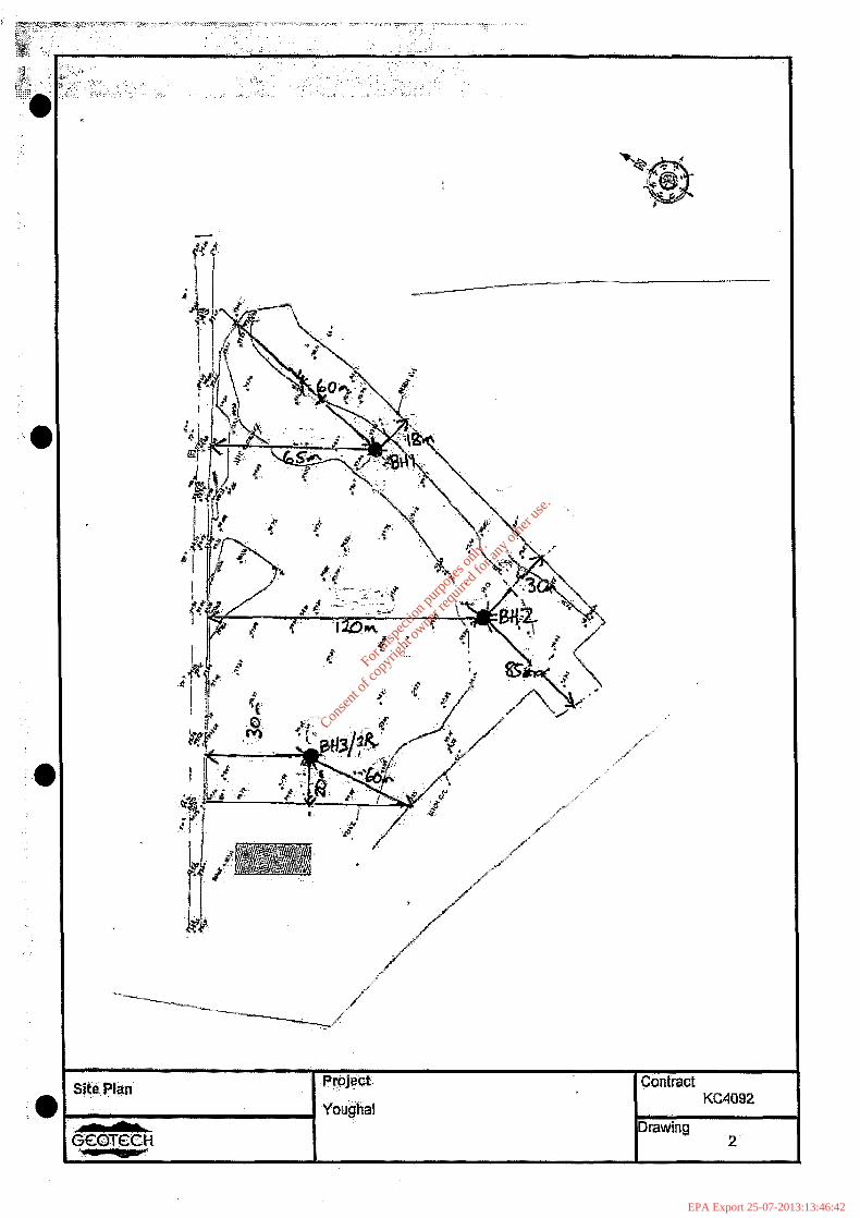
The exploratory hole locations were selected by SWS as shown on the Site Plan in Enclosure B.
The locations were set out from local features. The reduced levels were surveyed by GSL relative
to Ordnance Datum (Malin), using information on a temporary benchmark supplied by SWS.
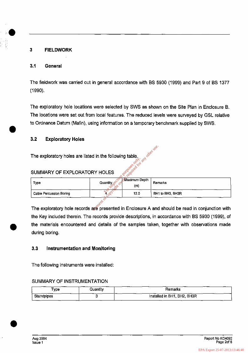
3.2 Exploratory Holes
The exploratory holes are listed in the following table.
SUMMARY OF EXPLORATORY HOLES
We Quantity Maximum Depth
Remarks 0-N
Cable Percussion Boring
I I I
4 12.0 BHI to BH3, BHBR
The exploratory hole records are presented in Enclosure A and should be read in conjunction with
the Key included therein. The records provide descriptions, in accordance with BS 5930 (1999), of
the materials encountered and details of the samples taken, together with observations made
during boring.
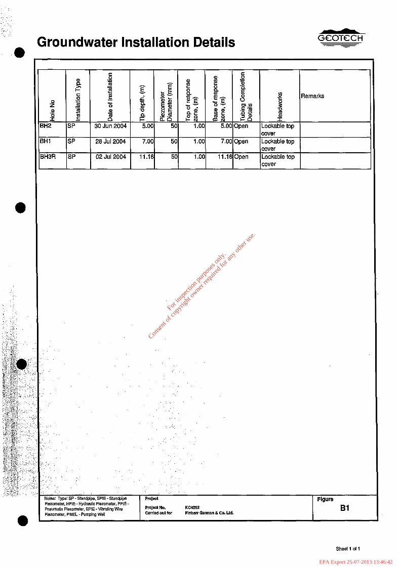
3.3 Instrumentation and Monitoring
The following instruments were installed:
SUMMARY OF INSTRUMENTATION
Type Standpipes
Quantity
3
Remarks
Installed in BHI, BH2, BHBR
Aug 2004 Issue 1
Report No KC4092 Page 20f 8
For
insp
ectio
n pur
pose
s only
.
Conse
nt of
copy
right
owne
r req
uired
for a
ny ot
her u
se.
EPA Export 25-07-2013:13:46:40
The instruments installed in the exploratory holes are shown on the logs and also detailed in
Enclosure 6. Records of groundwater monitoring carried out by GSL after the fieldwork period are
also presented in Enclosure B.
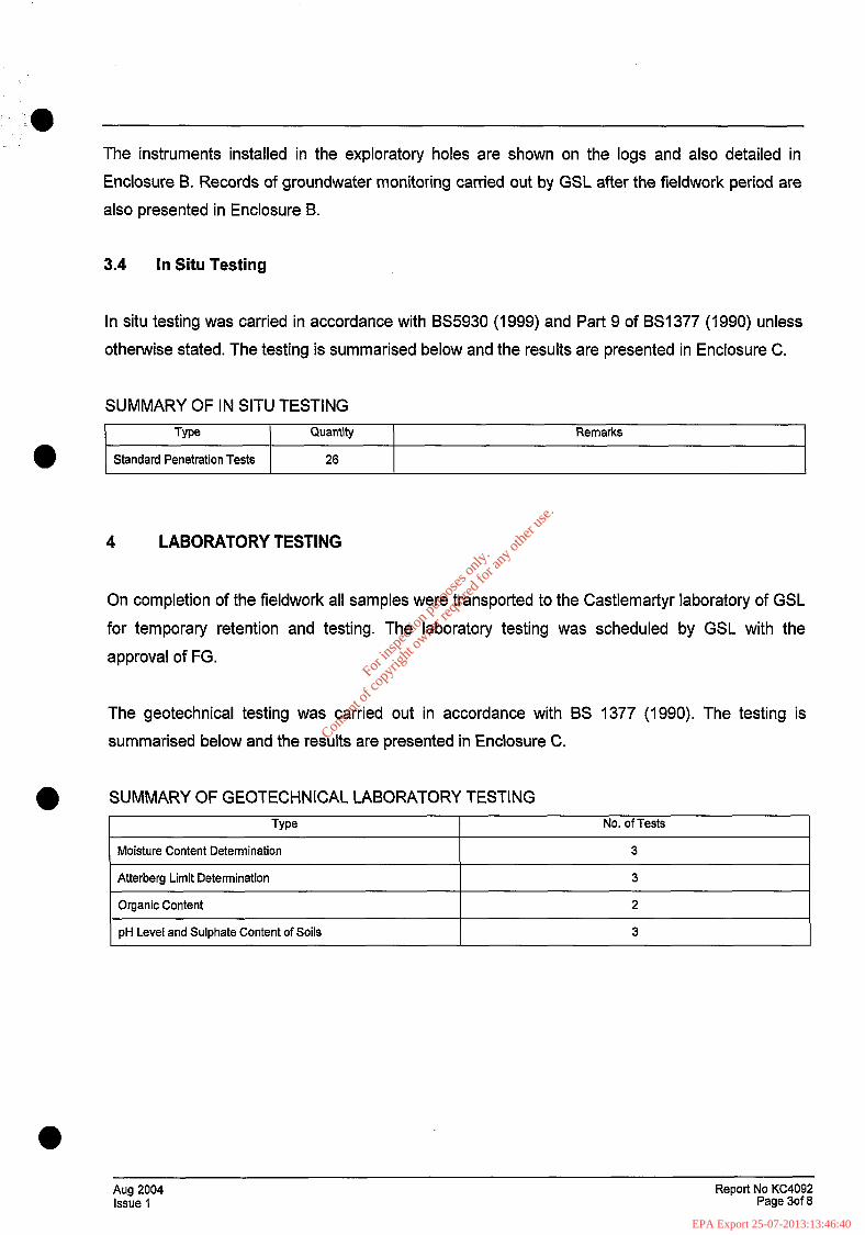
3.4 In Situ Testing
In situ testing was carried in accordance with BS5930 (1999) and Part 9 of BS1377 (1990) unless
otherwise stated. The testing is summarised below and the results are presented in Enclosure C.
SUMMARY OF IN SITU TESTING
I Type I Quantity Remarks I
Standard Penetration Tests 26
LABORATORY TESTING
On completion of the fieldwork all samples were transported to the Castlemartyr laboratory of GSL
for temporary retention and testing. The laboratory testing was scheduled by GSL with the
approval of FG.
The geotechnical testing was carried out in accordance with BS 1377 (1990). The testing is
summarised below and the results are presented in Enclosure C.
SUMMARY OF GEOTECHNICAL LABORATORY TESTING
Type No. of Tests
Moisture Content Determination I 3 I
Atterberg Limit Determination I 3 I
Organic Content
pH Level and Sulphate Content of Soils
2
3
Aug 2004 Report No KC4092 Issue 1 Page 3of 6
For
insp
ectio
n pur
pose
s only
.
Conse
nt of
copy
right
owne
r req
uired
for a
ny ot
her u
se.
EPA Export 25-07-2013:13:46:40
5 GROUND CONDITIONS AND GROUNDWATER
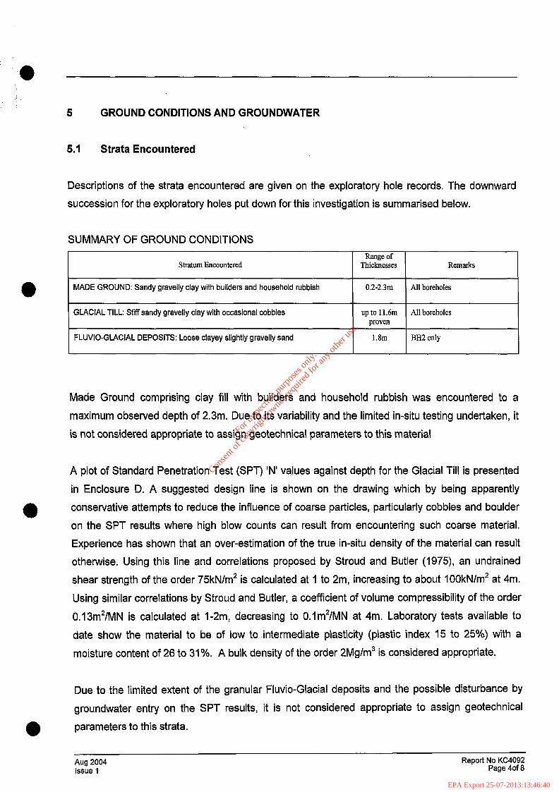
5.1 Strata Encountered
Descriptions of the strata encountered are given on the exploratory hole records. The downward
succession for the exploratory holes put down for this investigation is summarised below.
SUMMARY OF GROUND CONDITIONS Range of
Stratum Encountered Thicknesses Remarks
l MADE GROUND: Sandy gravelly clay with builders and household rubbish 0.2-2.3111 All boreholes
GLACIAL TILL: Stiff sandy gravelly clay with occasional cobbles I
up to 11.6m All boreholes proven I
FLUVIO-GLACIAL DEPOSITS: Loose clayey slightly gravelly sand I
1.8m BH2 only I
Made Ground comprising clay fill with builders and household rubbish was encountered to a
maximum observed depth of 2.3m. Due to its variability and the limited in-situ testing undertaken, it
is not considered appropriate to assign geotechnical parameters to this material
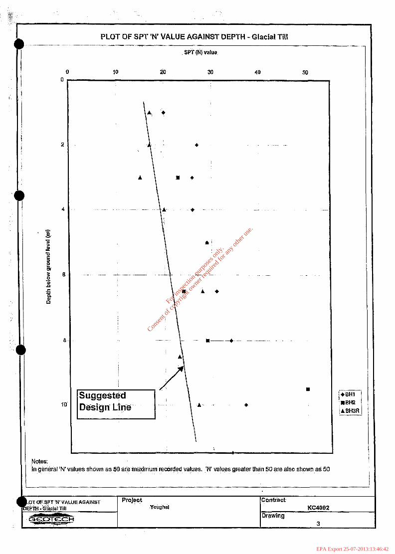
A plot of Standard Penetration Test (SPT) ‘N’ values against depth for the Glacial Till is presented
in Enclosure D. A suggested design line is shown on the drawing which by being apparently
conservative attempts to reduce the influence of coarse particles, particularly cobbles and boulder
on the SPT results where high blow counts can result from encountering such coarse material.
Experience has shown that an over-estimation of the true in-situ density of the material can result
otherwise. Using this line and correlations proposed by Stroud and Butler (1975), an undrained
shear strength of the order 75kN/m2 is calculated at 1 to 2m, increasing to about 100kN/m2 at 4m.
Using similar correlations by Stroud and Butler, a coefficient of volume compressibility of the order
0.13m2/MN is calculated at I-2m, decreasing to 0.1m2/MN at 4m. Laboratory tests available to
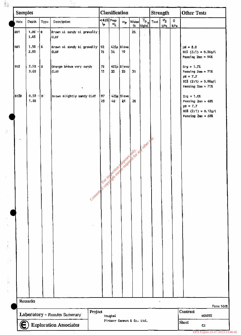
date show the material to be of low to intermediate plasticity (plastic index 15 to 25%) with a
moisture content of 26 to 31%. A bulk density of the order 2Mg/m3 is considered appropriate.
Due to the limited extent of the granular Fluvio-Glacial deposits and the possible disturbance by
groundwater entry on the SPT results, it is not considered appropriate to assign geotechnical
parameters to this strata.
Aug 2004 Issue 1
Report No KC4092 Page 40f 8
For
insp
ectio
n pur
pose
s only
.
Conse
nt of
copy
right
owne
r req
uired
for a
ny ot
her u
se.
EPA Export 25-07-2013:13:46:40
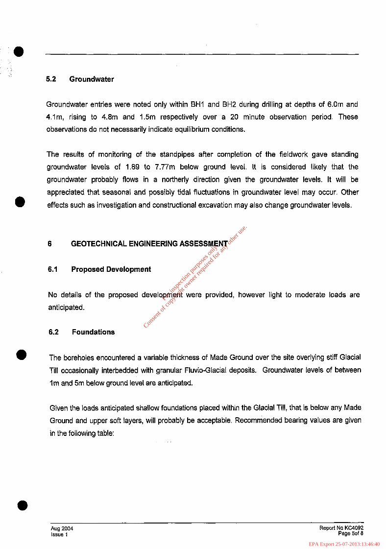
5.2 droundwater
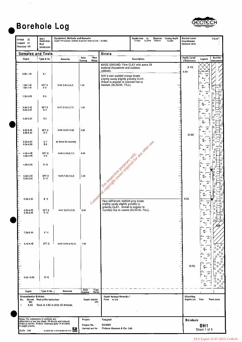
Groundwater entries were noted only within BHI and BH2 during drilling at depths of 6.0m and
4.lm, rising to 4.8m and 1.5m respectively over a 20 minute observation period. These
observations do not necessarily indicate equilibrium conditions.
The results of monitoring of the standpipes after completion of the fieldwork gave standing
groundwater levels of 1.89 to 7.77m below ground level. It is considered likely that the
groundwater probably flows in a northerly direction given the groundwater levels. It will be
appreciated that seasonal and possibly tidal fluctuations in groundwater level may occur. Other
0 effects such as investigation and constructional excavation may also change groundwater levels.
6 GEOTECHNICAL ENGINEERING ASSESSMENT
6.1 Proposed Development
No details of the proposed development were provided, however light to moderate loads are
anticipated.
6.2 Foundations
The boreholes encountered a variable thickness of Made Ground over the site overlying stiff Glacial
Till occasionally interbedded with granular Fluvio-Glacial deposits. Groundwater levels of between
I m and 5m below ground level are anticipated.
Given the loads anticipated shallow foundations placed within the Glacial Till, that is below any Made
Ground and upper soft layers, will probably be acceptable. Recommended bearing values are given
in the following table:
Aug 2004 Issue 1
Report No KC4092 Page 5of 8
For
insp
ectio
n pur
pose
s only
.
Conse
nt of
copy
right
owne
r req
uired
for a
ny ot
her u
se.
EPA Export 25-07-2013:13:46:40
lm
k 2m
3m
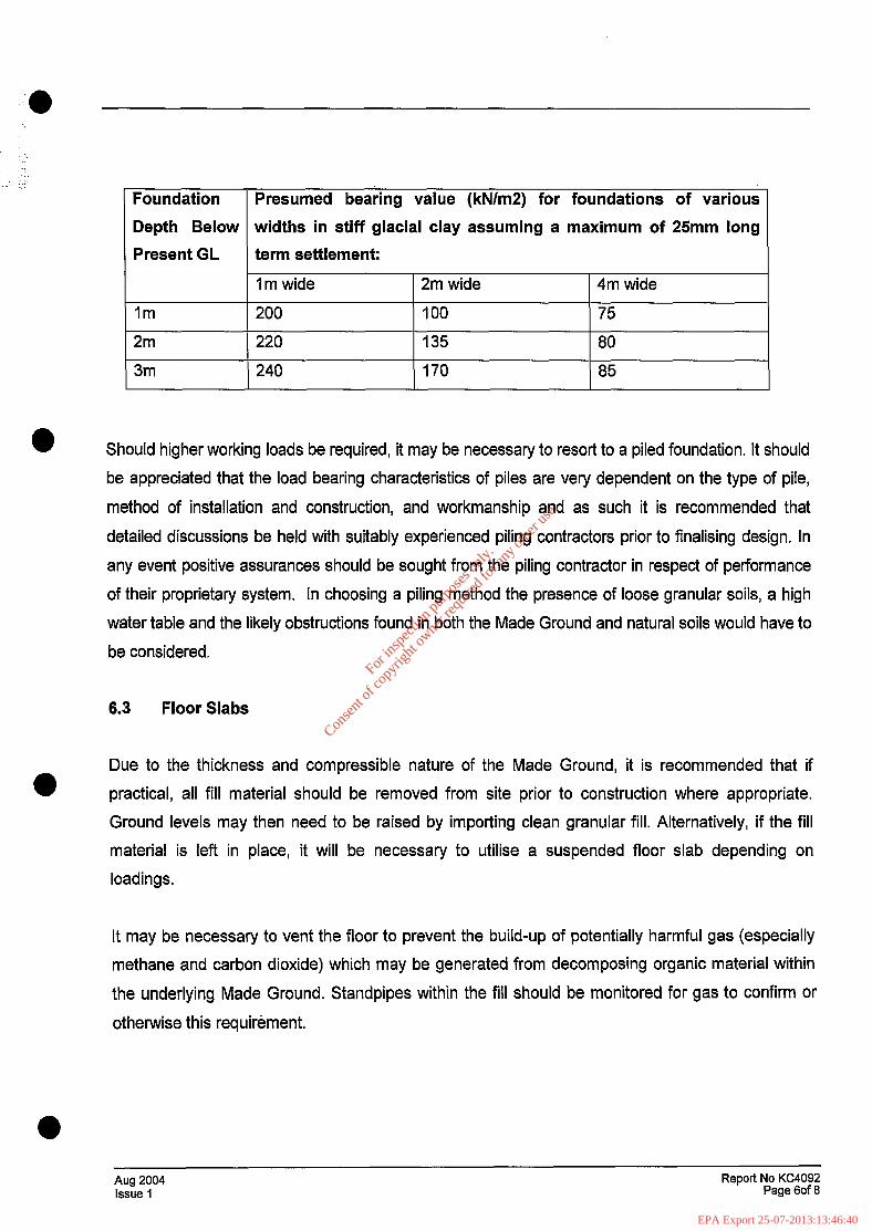
Presumed bearing value (kN/mZ) for foundations of various
widths in stiff glacial clay assuming a maximum of 25mm long
term settlement:
1 m wide 2m wide 4m wide
200 100 75
220 135 80
240 170 85
Should higher working loads be required, it may be necessary to resort to a piled foundation. It should
be appreciated that the load bearing characteristics of piles are very dependent on the type of pile,
method of installation and construction, and workmanship and as such it is recommended that
detailed discussions be held with suitably experienced piling contractors prior to finalising design. In
any event positive assurances should be sought from the piling contractor in respect of performance
of their proprietary system. In choosing a piling method the presence of loose granular soils, a high
water table and the likely obstructions found in both the Made Ground and natural soils would have to
be considered.
6.3 Floor Slabs
0
Due to the thickness and compressible nature of the Made Ground, it is recommended that if
practical, all fill material should be removed from site prior to construction where appropriate.
Ground levels may then need to be raised by importing clean granular fill. Alternatively, if the fill
material is left in place, it will be necessary to utilise a suspended floor slab depending on
loadings.
It may be necessary to vent the floor to prevent the build-up of potentially harmful gas (especially
methane and carbon dioxide) which may be generated from decomposing organic material within
the underlying Made Ground. Standpipes within the fill should be monitored for gas to confirm or
otherwise this requirement.
Aug 2004 Issue 1
Report No KC4092 Page 6of 8
For
insp
ectio
n pur
pose
s only
.
Conse
nt of
copy
right
owne
r req
uired
for a
ny ot
her u
se.
EPA Export 25-07-2013:13:46:40
6.4 Excavations and Groundwater
Any excavations required within the strata observed should be easily accomplished using
conventional back-acting hydraulic plant. However excavations may require support even at
shallow depths. Any excavation requiring man entry should be fully supported or cut back to a safe
slope in accordance with normal safe site practice.
As groundwater was encountered at relatively shallow depths, it is possible that groundwater may
be encountered, especially if granular pockets are encountered within the Glacial Till. Groundwater
levels may rise to depths of possibly I-2m in places, and localised pockets of groundwater may
0
occur within Made Ground. Generally, excavations within the Glacial Till should be easily
controlled by pumping from internal filtered sumps. Any excavations into gravel are expected to
encounter strong groundwater inflow which will require extensive dewatering.
6.5 Infrastructure
Any access roads, car parks or other areas of hardstanding may only be constructed on the Made
Ground after first removing at least the top 500mm of Made Ground and replacing by granular fill
underlain by a geotextile membrane or grid (Terram or similar) to prevent mixing of the granular
material with the underlying soft material. Placing layers of geogrid within the granular material can
reduce the total thickness of road construction required. For design, a CBR of not exceeding 1%
should be used where founding on the Made Ground. Higher CBRs may be possible where any
road, hardstanding etc is. located on natural soils. In-situ CBR tests should be carried out to
confirm the CBR values.
Any underground services should incorporate some flexibility in order to tolerate further settlement
of the Made Ground which may occur.
6.6 Chemical Considerations for Buried Concrete
The results of three tests for sulphate concentration and pH levels on selected soil samples show
sulphate concentrations of between 0.06 and 0.12 grams per litre (as SOS) and pH values of
between 7.7 and 8.0. These test results indicate a Design Sulphate Class 1 (DS-1) and Aggressive
Chemical Environment for Concrete Class 1 (ACEC-1) (BRE Special Digest 1). No special
l precautions are therefore recommended with regards to concrete design. Due to the possibility of
Aug 2004 Issue 1
Report No KC4092 Page 7of 8
For
insp
ectio
n pur
pose
s only
.
Conse
nt of
copy
right
owne
r req
uired
for a
ny ot
her u
se.
EPA Export 25-07-2013:13:46:41
saline groundwater, it is recommended that any reinforcement in concrete is protected from
chloride corrosion by covering with at least 30mm of good quality concrete.
Prepared By A. Garne B.Sc., M.Sc., F.G.S.
Reviewed By M.N. Harris B.Sc., M.Sc., DIC, FGS, MICE, C Eng.
Approved for Issue By
REFERENCES
British Standards and Codes of Practice
BS 1377 : 1990 : Methods of test for soils for civil engineering purposes. British Standards Institution.
BS 5930 : 1999 : Code of practice for site investigations. British Standards Institution.
Maps
GSI Sheet 25 : 1995 : “Geology of South Cork”. 1:100000 geological map (solid). Geological
a Survey of Ireland.
Ordnance Survey Discovery Series. Sheet 81 : 2001 : Cork. 150000. Ordnance Survey of Ireland.
Publications and Reports
BS 8004 ; 1986. Code of Practice for Foundations. British Standards Institution.
BRE Special Digest 1.2001. Concrete in aggressive ground. Part 1: Assessing the aggressive chemical environment. Building Research Establishment.
Stroud M A and Butler F G (1975): The standard penetration test and the engineering properties of glacial materials, Proc of the engineering properties of glacial materials. Midlands Sot SMFE.
.
l Aug 2004 Issue 1
Report No KC4092 Page 8of 8
For
insp
ectio
n pur
pose
s only
.
Conse
nt of
copy
right
owne
r req
uired
for a
ny ot
her u
se.
EPA Export 25-07-2013:13:46:41
GCOTGCH
ENCLOSUREA
EXPLORATORY HOLE RECORDS
Key to Exploratory Hole Records
Borehole Logs Key
BHI to BH3, BH3R
Aug 2004 Issue 1
Report No KC4092 Enclosure A
For
insp
ectio
n pur
pose
s only
.
Conse
nt of
copy
right
owne
r req
uired
for a
ny ot
her u
se.
EPA Export 25-07-2013:13:46:41
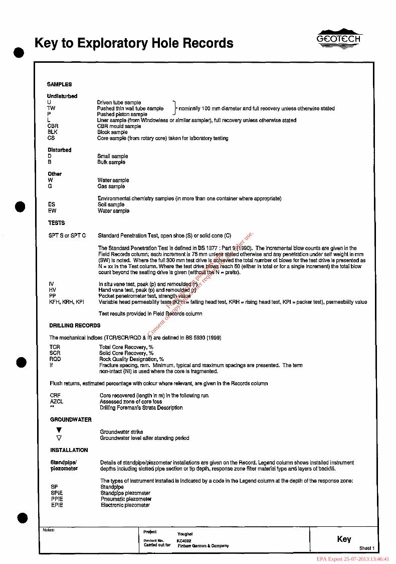
l Key to Exploratory Hole Records GczmiT - -
SAMPLES
Undlsturbed
iv
r CBR BLK cs
Dlsturbed
E
Driven tube sample Pushed thin wall tube sample nominally 100 mm diameter and full recovery unless otherwise stated Pushed piston sample Liner sample (from Windowless or similar sampler), full recovery unless otherwise stated CBR mould sample Block sample Core sample (from rotary core) taken for laboratory testing
Small sample Bulk sample
Other W G
ES EW
TESTS
Water sample Gas sample
Environmental chemistry samples (in more than one container where appropriate) Soil sample Water sample
SPT S or SPT C Standard Penetration Test, open shoe (S) or solid cone (C)
The Standard Penetration Test is defined in BS 1377 : Part 9 (1990). The incremental blow counts are given in the Fisld Records column; each increment is 75 mm unless stated otherwise and any penetration under self weight in mm (SW) is noted. Where the full 300 mm test drive is achieved the total number of blows for the test drive is presented as N = xx in the Test column. Where the test drive blows reach 50 (either in total or for a single increment) the total blow count beyond the seating drive is given (without the N = prefix).
!” PP KFH, KRH, KPI
In situ vane test, peak (p) and remoulded (r) Hand vane test, peak (p) and remoulded (r) Pocket penetrometer test, strength value Variable head permeability tests (KFH = falling head test, KRH = rising head test, KPI = packer test), permeability value
Test results provided in Field Records column
DRILLING RECORDS
The mechanical indices (TCR/SCR/RQD & If) are defined in BS 5930 (1999)
TCR Total Core Recovery, % SCR Solid Core Recovery, % RQD Rock Quality Designation, % If Fracture spacing, mm. Minimum, typical and maximum spacings are presented. The term
non-intact (NI) is used where the core is fragmented.
Flush returns, estimated percentage with colour where relevant, are given in the Records column
CRF AZCL l t
Core recovered (length in m) in the following run Assessed zone of core loss Drilling Foreman’s Strata Description
GROUNDWATER
v Groundwater strike V Groundwater level after standing period
INSTALLATION
Standplpel plezometer
&E PPIE EPIE
Details of standpipe/piezometer installations are given on the Record. Legend column shows installed instrument depths including slotted pipe section or tip depth, response zone filter material type and layers of backfill.
The types of instrument installed is indicated by a code in the Legend column at the depth of the response zone: Standpipe Standpipe piezometer Pneumatic piezometer Electronic piezometer
Notes: Youghal
KC4092 Key Canled out for Flnbaw Gannon & Company Shed
For
insp
ectio
n pur
pose
s only
.
Conse
nt of
copy
right
owne
r req
uired
for a
ny ot
her u
se.
EPA Export 25-07-2013:13:46:41
Key to Exploratory Hole Records emi e
--
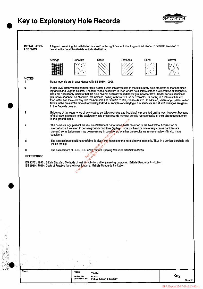
INSTALLATION A legend describing the installation is shown in the rightmost column. Legends additional to BS5930 are used to LEGENDS describe the backfill materials as indicated below.
Arisings Concrete Grout Bentonite Sand Gravel
m N m pj fgq
NOTES 1 Strata legends are in accordance with BS 5930 (1999).
2 Water level observations of discernible events during the advancing of the exploratory hole are given at the foot of the log and in the Legend column. The term “none observed” is used where no discrete entries are identified although this does not necessarily indicate that the hole has not been advanced below groundwater level. Under certain conditions groundwater cannot be observed, for instance, drilling with water flush or overwater, or boring at a rate much faster than water can make its way into the borehole (ret BS5930 : 1999, Clause 47.2.7). In addition, where appropriate, water levels in the hole at the time of recovering individual samples or carrying out in situ tests and at shift changes are given in the Records column.
3 Evidence of the occurrence of very coarse particles (cobbles and boulders) is presented on the logs, however, because of their size in relation to the exploratory hole these records may not be fully representative of their size and frequency in the ground mass.
4 The borehole logs present the results of Standard Penetration Tests recorded in the field without correction or interpretation. However, in certain ground conditions (eg high hydraulic head or where very coarse particles are present) some judgement may be necessary in considering whether the results are representative of in situ mass conditions.
5 The declination of bedding and joints is given with respect to the normal to the core axis. Thus in avertical borehole this will be the dip.
6 The assessment of SCR, RQD and Fracture Spacing excludes artificial fractures
REFERENCES
BS 1377 : 1990 : British Standard Methods of test for soils for civil engineering purposes. British Standards Institution BS 5930 : 1999 : Code of Practice for site investigations. British Standards Institution
Notes:
‘, is : ., ‘:)
Pmlect Youghal
Crnlcw, uo. KC4OgP Carrled out ior
Key Flnbarr Gannon &Company
Sheet
For
insp
ectio
n pur
pose
s only
.
Conse
nt of
copy
right
owne
r req
uired
for a
ny ot
her u
se.
EPA Export 25-07-2013:13:46:41
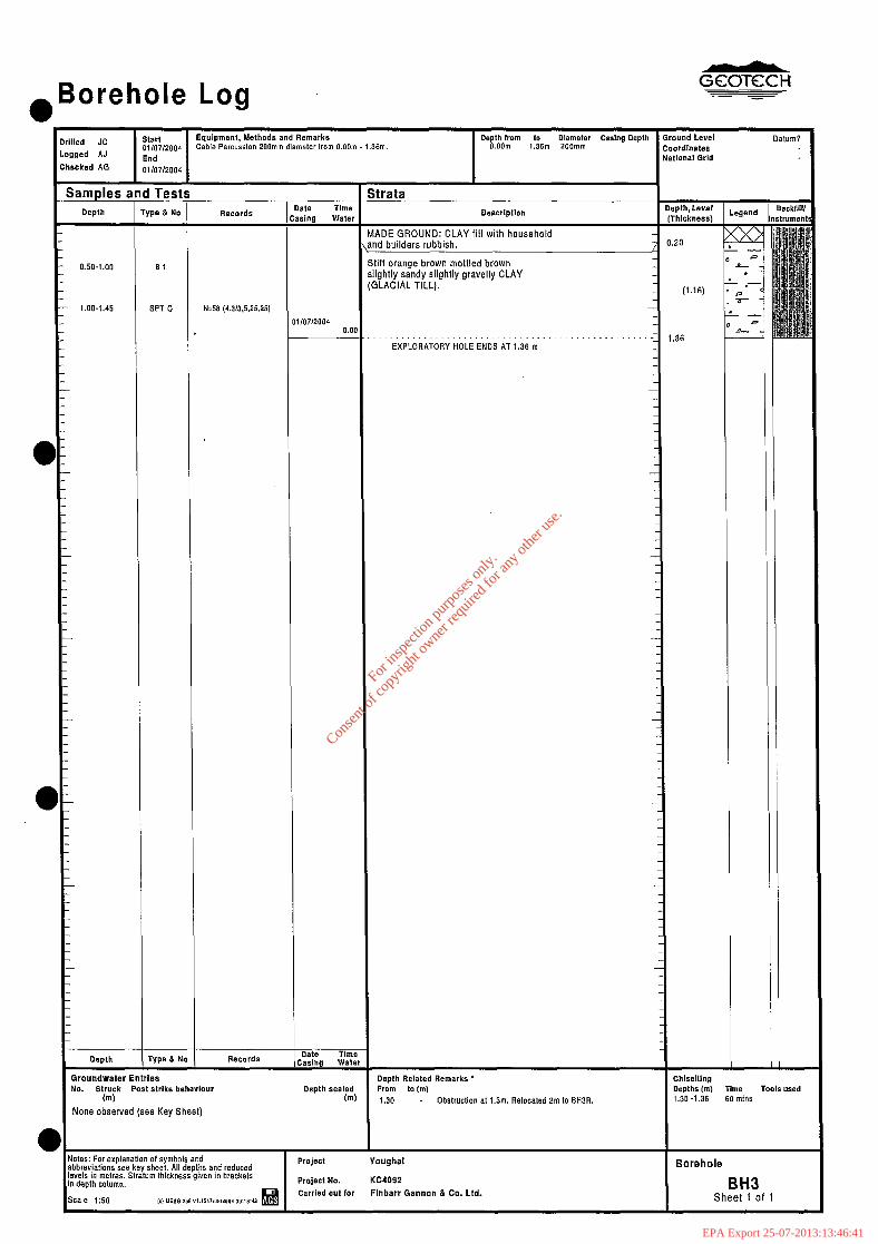
.Borehole Log
N=58 (4,3/3.5.25,251
Ike behaviaur 61
None observed (see Key Sheet) Obstruction at i.3m. Relocaled 2m to BHIR.
Carried o”t for Flnbarr Gannan d Co. Ltd. Sheet 1 of 1
For
insp
ectio
n pur
pose
s only
.
Conse
nt of
copy
right
owne
r req
uired
for a
ny ot
her u
se.
EPA Export 25-07-2013:13:46:41
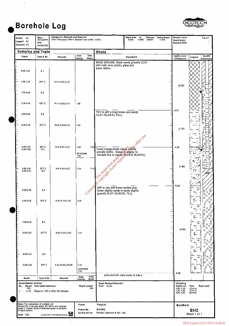
. Borehole Log
Drilled JC Logged AJ
Checked AG
Depth
start Equipment, Methods and Remarks Depth from to Diameter Casing Depth O.OOrn 29/06/2004 Cable Percussion 200mm diameter from O.OOm - 6.66m. 9mm 200mm 7.50m
End 3610612064
Test _s ltrata pe & No
Samples and late Time 1stng water Description I
M ADE GROUND: Black sandy gravelly CLAY w ith cloth, wire, plastic, glass and Pi aper debris.
- 0.50-1.00 El
- 1.00-1.45 SPT C N=if (3,2/2,3,3.3)
- 1.50-2.00 82
- 2.00-2.45 SPT C N=l, (2,X3,3,3.2) 50
- 6.00-6.50
6.50-6.95
Depth
SPT C
SPT C 84
SPT C B5
86
SPT C
87
SPT C
SPT C
ryps a N
N=23 (3,3/4,6,7,6)
N=S (2,2,,,2.2.3)
N.24 (5,5/9.5,7.6)
N=29 f4,5/5,7,6,9)
N&4 (5,6/6.8,25.25)
Groundwater Entrles NC& Struck Post strike behavfour
(ml 1 4.10 Rose to 1.50 m after 20 minutes.
.oo 1.5
910612004 .oo
i.00
7.50
30/06/2004 7.50
Date Tim, CaShg wat1
Depth sealed (m
irm to stiff orange brown very sandy LAY (GLACIAL TILL).
oose orange brown clayey slightly ravelly SAND. Gravel is angular to
ounded fine to coarse (FLUVIO-GLACIAL)
-
Stiff to very stiff brown mottled grey uown slightly sandy to sandy slightly gravelly CLAY (GLACIAL TILL).
-
EXPLORATORY HOLE ENDS AT 9.99 m
Depth Aelatad Remarks * Prom to b-4
Jotes: For snplanation of symbols and lbbrevialions see key shset. All depths and reduced evels in metres. Stratum thickness given in brackels n depth column.
icals 150 (0, MESG 218 “l.l5l7,08,2004 08:18:21
Project Youghal
Project No. KC4092 Carrfed out tar Finbarr Gannon & Co. Ltd.
ound Level ordinates tional Grid
Datum?
(2.30)
(4.08)
9.88
Chiselllng Depths (ml TllllS Tools used
0.60 -1.00 1.50 -1.68 :; ;ic: 9.80 -9.86 60 mins
Borehole
BH2 Sheet 1 of 1
For
insp
ectio
n pur
pose
s only
.
Conse
nt of
copy
right
owne
r req
uired
for a
ny ot
her u
se.
EPA Export 25-07-2013:13:46:41
e Borehole Log
4
4
Dr LO Ch
65 blows No recovery
N=26 (4.5/6,6,7,7)
- 5.00-5.45 N4?9 ,7,818,7,6,8)
- 6.00-6.50
alrlke behavlour
1 6.00 Rose to 4.80 m after 20 minutes.
B, h
e il
gravelly CLAY. Gravel is angular to rounded tine to coarse [GLACIAL TILL).
Carried out for Finharr Gannon & Co. Ltd.
For
insp
ectio
n pur
pose
s only
.
Conse
nt of
copy
right
owne
r req
uired
for a
ny ot
her u
se.
EPA Export 25-07-2013:13:46:41
Drilled JC ged AJ Lag
CIW eked AG
s hnd Tests amples i Depth
10.00-10.45 10.00-10.45
be & No
r D 16
ii .00-i 1.50 E 17
11.50-11.95 ;PT S
Depth rype a E:
Records
N=37 (5,5/7,9,10.12)
N=34 /7.7/6,8.10,10) II
2! II
“( . I :
.a,’
‘, i,. 1:
_.L , . :
; . . ; ,,~’
.Bo;ehole Log start Equipment, Methods and Remarks Depth from to Diameter Casing Depth Ground Level 25/06/2004 Cable Percussion 200mm diameter from O.OOm - 12.00m. o.oom 12.00m 200mm 10.50m Coordinates End Natis onal Grid
25/06/2004
trata late Time Ising wate 60
- gsnd
Records
Groundwater Entries No. Struck Post strike behavlour
W
1.50
i/OS/2004 1.50 d
-
Dale cashlg ws
Depth seals (1
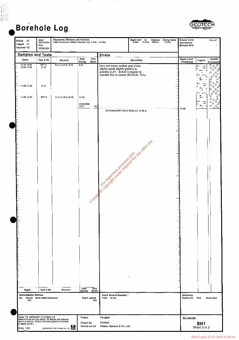
ry stiff brown mottled grey brown ghtly sandy slightly gravelly to avelly CLAY. Gravel is angular to unded fine to coarse (GLACIAL TILL).
EXPLORATORY HOLE ENDS AT 12.00 m
-
-
-
Depth Related Remarks l
FIWll to (ml
lotes: For explanation 01 symbols and abbreviations see key sheet. All depths and reduced aels in metres. Stratum thickness given in brackets n depth column.
Me 1:50 ,c, UESE 208 “,.,I17!0I,20P. oP:17:48
Project Youghal
Pro/ect No. KC4092 Carried out for Finbarr Gannon & Co. Ltd.
IO
:hlsolllng tsptne (In, Time Tools used
- P
L . . .-
F
- P
L . .-
D ( r-
- P
L L
-
Datum?
- ktlll, Ill=“,
10 01
0
)OO 0
0 ) 0
“d
,>
0 )O
0
Barehole
BHI Sheet 2 of 2
For
insp
ectio
n pur
pose
s only
.
Conse
nt of
copy
right
owne
r req
uired
for a
ny ot
her u
se.
EPA Export 25-07-2013:13:46:42
*Borehole Log
Cable Percussion 200mm diameter from O.OOm - 11.16m.
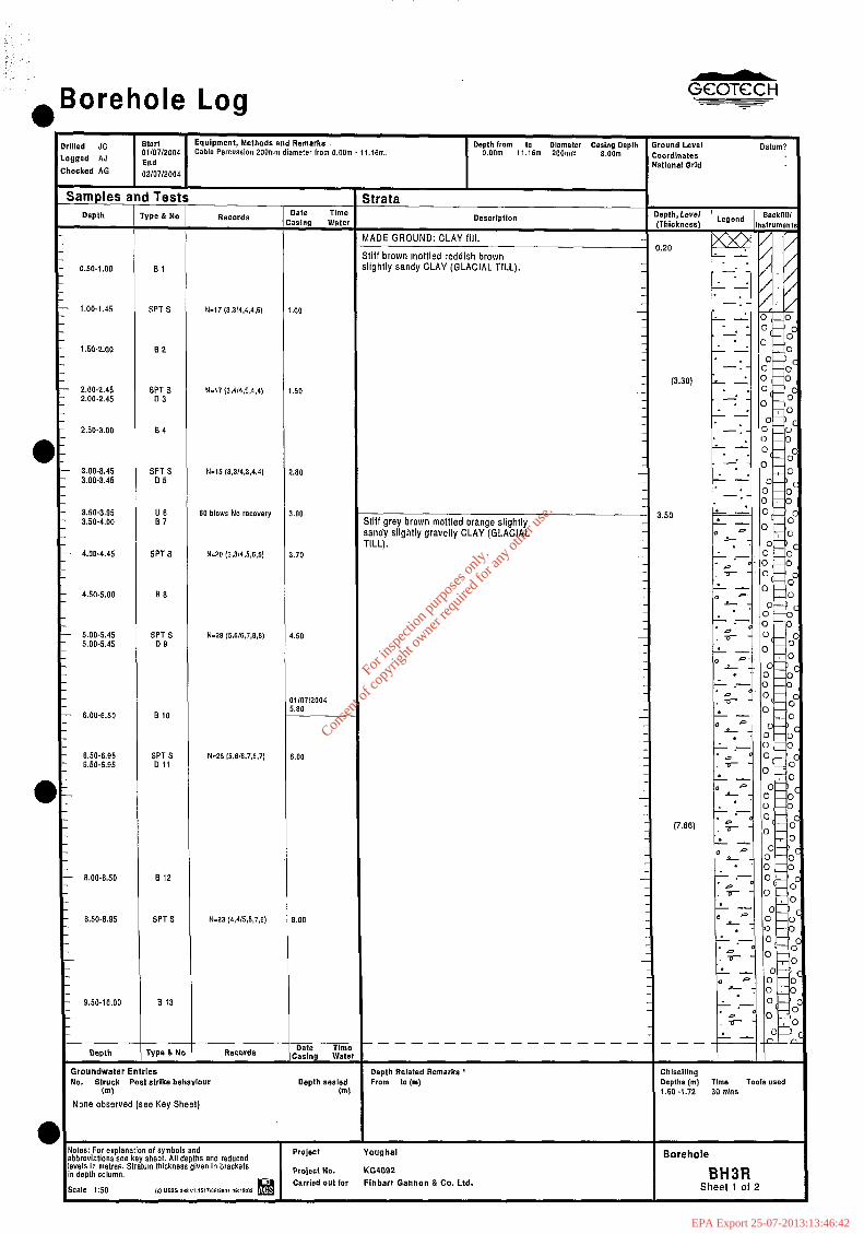
N-17 (3.314,4,4.5)
N=i7 (3.4,4,6.4,,)
N=15 (3.3/4.3,4,4)
60 blows No recovery
N=29 (5,616,7,3.3)
N=28 (5,616.7.3,7)
N=23 (4,4,5,5,7,6)
ike behavlour (ml
None observed (see Key Sheet)
I
dolss: For explanation of symbols and abbreviations SBB key shest. All depths and reduced
Project Yaughal Borehole evsls in m&es. Stratum thickness given in brackets n depth column. Project No. KC4092
k3 Carried out for Finbarr Gannon &Co. Ltd.
BH3R icab3 150 (0 UESO 288 “1.151710811001 WlB (II Sheet 1 of 2
For
insp
ectio
n pur
pose
s only
.
Conse
nt of
copy
right
owne
r req
uired
for a
ny ot
her u
se.
EPA Export 25-07-2013:13:46:42
“ , - ,
aBorehole Log
Drl LO Ch
I
lled JC start Equipment, Methods and Remarks Depth from ,o Diameter Casing Depth Ground Level Datum?
gged AJ 01/07/2004 Cable Percussion 200mm diameter lrom O.OOm 11.16m. o.oom 11.16m 200mm B.OOrn Coordinates End Natlonal Grid
ecked AG 02/07/2004
samples and Tests Strata Depth Type L No Records
Date Time llescript1on
Oepth,Level BacktIll casing Wai*r (Thickness)
Legend lnrtrumer
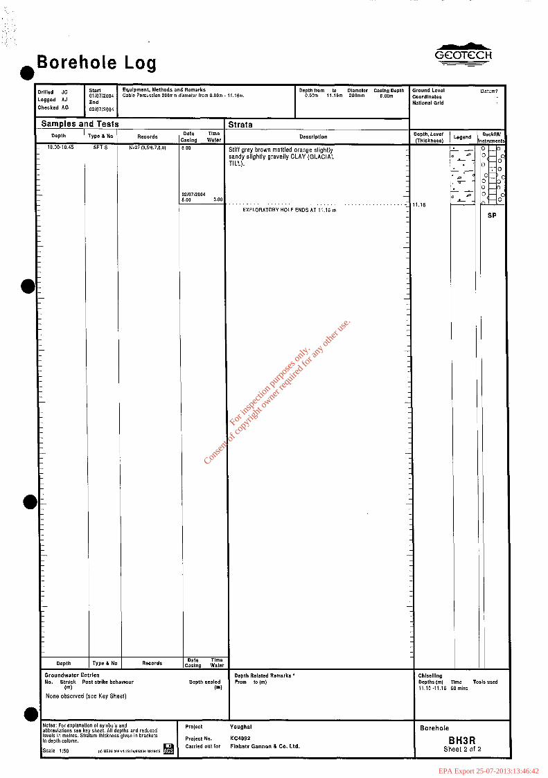
10.00.10.45 SPT S N-27 (3.5/6,7,6,8) 8.00 Stiff grey brown mottled orange slightly L, 0-c sandy slightly gravelly CLAY (GLACIAL a p o- TILL).
L-
I .O,: . .- -
*.a o -) b - 0”~c
. _ 0-c 02/07/2004 6.00 0.00
0 0 0- L- (-(
11.16 EXPLORATORY HOLE ENDS AT 11.16 m
SP
Depth Type & No Records Date Time ,casing water
Groundwater Entries Depth Related Remarks * Chlselllng NO. Struck Post strike behavtour Depth sealed From to(m) Depths(m) Time Tools used
@I (m) 11.10-11.16 60 mins
None observed (see Key Sheet)
dotes: For explanation of symbols and abbreviations see key sheet. All depths and reduced evels in mslres. Stratum thickness given in brackets n depth column.
scale 1:50 Ik) MESG a* “1.,617,08,2001 OW8’05
Project Youghal Borehole
Project No. KC4092
Carried out for BH3R
Finharr Gannon & Co. Ltd. Sheet 2 of 2
For
insp
ectio
n pur
pose
s only
.
Conse
nt of
copy
right
owne
r req
uired
for a
ny ot
her u
se.
EPA Export 25-07-2013:13:46:42
GCOTKH
ENCLOSUREB
INSTRUMENTATION MONITORING
Installation Details
Groundwater Monitoring
I31
B2
For
insp
ectio
n pur
pose
s only
.
Conse
nt of
copy
right
owne
r req
uired
for a
ny ot
her u
se.
EPA Export 25-07-2013:13:46:42
ndwater Installation Details
c c d .o F
z 8 z .g 9
s 5 E 5 s s P
S ki- 3 8 E c” ?!A Y Remarks
‘2 P g 5 E 5%
8 Ezi EE $ & E Lo -55-
a, s 3s .
B CE
0 E H2= SP-
m
30 Jut 2004
.a .- .- sfg $2 E 8 I- LO I-N I23 130”
i I
5.00 50 1 .oo 5.00 Open Lockable top cover
Hi SP 28 Jul2004 7.00 50 1 .oo 7.00 Open Lockable top cover
H3R SP 02 Jul2004 11.16 50 1 .oo 11.16 Open Lockable top cover
‘_ ._’ I’ ..: I
,’ . . . ‘.
:- Notes: Type: SP - Standpipe, SPIE - Standpipe Plezometer, HPIE - Hydraulic Piezometer, PPIE - Pneumatic Piezameter, EPIE - Vibrating Wire Plezometer, PWEL - Pumplng Well
1
:
: Project
Project No. Kc4092 Carded out for Flnbarr Cannon &Co. Ltd.
Figure
Bl
Sheet 1 of 1
For
insp
ectio
n pur
pose
s only
.
Conse
nt of
copy
right
owne
r req
uired
for a
ny ot
her u
se.
EPA Export 25-07-2013:13:46:42

l
Groundwater Monitoring Ge5%%
-- e
Notes: Type: SP - StandpIpe, SPIE - Standpipe ho]eot Yaughal Sheet Plezameter, HPIE - Hydraullo Plezometer, PPIE - Pneumatlo Plezometer, EPlE - Vlbratlng Wire Plezometer, PWEL _ Pumping Well
ProJeot No. Car&d out for
KC4092 Flnbarr Gsnnon &Co. Ltd.
Sheet 1 of 1
For
insp
ectio
n pur
pose
s only
.
Conse
nt of
copy
right
owne
r req
uired
for a
ny ot
her u
se.
EPA Export 25-07-2013:13:46:42
GCOTCCH
,, /..j
ENCLOSURE C
GEOTECHNICAL LABORATORY TEST RESULTS
Key to Geotechnical Laboratory Results
Table of Index Properties Key c2
Aug 2004 Report No KC4092 Issue 1 Enclosure C
For
insp
ectio
n pur
pose
s only
.
Conse
nt of
copy
right
owne
r req
uired
for a
ny ot
her u
se.
EPA Export 25-07-2013:13:46:42
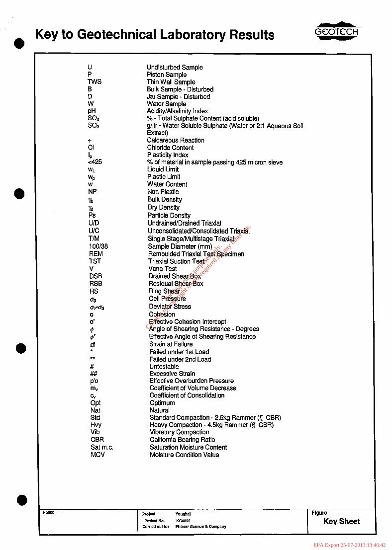
a Key to Geotechnical Laboratory Results Gem% - -
U
YWS B D W
!zo, so3
:I ‘P <425 WL
WP W
NP Ib yd
ED u/c T/M iOOl38 REM TST v DSB RSB RS 03
w(73
c C’
# #’ liTi * **
# ##I P’o m G Opt Nat Std HVY Vib CBR Sat m.c. MCV
Undisturbed Sample Piston Sample Thin Wall Sample Bulk Sample - Disturbed Jar Sample - Disturbed Water Sample Acidity/Alkalinity Index % - Total Sulphate Content (acid soluble) g/ltr - Water Soluble Sulphate (Water or 2:l Aqueous Soil Extract) Calcareous Reaction Chloride Content Plasticity Index % of material in sample passing 425 micron sieve Liquid Limit Plastic Limit Water Content Non Plastic Bulk Density Dry Density Particle Density Undrained/Drained Triaxial Unconsolidated/Consolidated Triaxial Single Stage/Multistage Triaxial Sample Diameter (mm) Remoulded Triaxial Test Specimen Triaxial Suction Test Vane Test Drained Shear Box Residual Shear Box Ring Shear Cell Pressure Deviator Stress Cohesion Effective Cohesion Intercept Angle of Shearing Resistance - Degrees Effective Angle of Shearing Resistance Strain at Failure Failed under 1st Load Failed under 2nd Load Untestable Excessive Strain Effective Overburden Pressure Coefficient of Volume Decrease Coefficient of Consolidation Optimum Natural Standard Compaction - 2.5kg Rammer (7 CBR) Heavy Compaction - 4.5kg Rammer (0 CBR) Vibratory Compaction California Bearing Ratio Saturation Moisture Content Moisture Condition Value
Notes: PmjBct Youghal Figure
Prnlm, No. KPdllP, Carried out for FInbarr Gannon & Company
Key Sheet
For
insp
ectio
n pur
pose
s only
.
Conse
nt of
copy
right
owne
r req
uired
for a
ny ot
her u
se.
EPA Export 25-07-2013:13:46:42
08 -
45
so - in
50 - aI3
,5a - ,m
rwn at sandy sl grawtly LAY
v.
lilt-l rlightly sandy CL&Y
s i
pM = a.0
5m C2:lj = u.wg/t Passing 2fnn = 94%
erg = 1.7% RMxiTng 2mn = 71% pR = 7.7 SO? (2~1) = O.OBa/t PaesiinQ i?ml = 74%
Qrg = 1.8% Passftkg J&ml = am%
= 3.7 SM (2:15 = Lk?g/t
znm = 60X
For
insp
ectio
n pur
pose
s only
.
Conse
nt of
copy
right
owne
r req
uired
for a
ny ot
her u
se.
EPA Export 25-07-2013:13:46:42
GCOTCCH
ENCLOSURE E
DRAWINGS
Site Location Plan
Site Plan
SPT vs Depth Plot
For
insp
ectio
n pur
pose
s only
.
Conse
nt of
copy
right
owne
r req
uired
for a
ny ot
her u
se.
EPA Export 25-07-2013:13:46:42
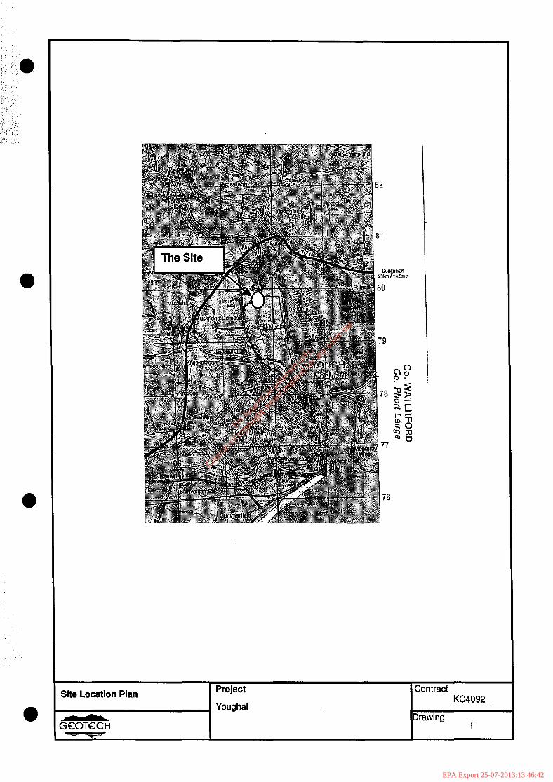
Site Location Plan Project
Youghal
Contract KC4092
Drawing 1
For
insp
ectio
n pur
pose
s only
.
Conse
nt of
copy
right
owne
r req
uired
for a
ny ot
her u
se.
EPA Export 25-07-2013:13:46:42
-
For
insp
ectio
n pur
pose
s only
.
Conse
nt of
copy
right
owne
r req
uired
for a
ny ot
her u
se.
EPA Export 25-07-2013:13:46:42
___.
For
insp
ectio
n pur
pose
s only
.
Conse
nt of
copy
right
owne
r req
uired
for a
ny ot
her u
se.
EPA Export 25-07-2013:13:46:42