
Conceptual Modular Design of Auto Body Frame Based on ...
26
Computer Modeling in Engineering & Sciences CMES, vol.122, no.1, pp.351-376, 2020 CMES. doi:10.32604/cmes.2020.08058 www.techscience.com/journal/CMES Conceptual Modular Design of Auto Body Frame Based on Hybrid Optimization Method Yonghong Zhao 1 , Changsheng Wang 2 , Huanquan Yuan 1 , Yongcheng Li 1 , Chunlai Shan 2 and Wenbin Hou 2, * Abstract: This article presents a systematic research methodology of modular design for conceptual auto body frame by hybrid optimization method. A modified graph-based decomposition optimization algorithm is utilized to generate an optimal BIW assembly topo model composed of “potential modules”. The consistency constraint function in collaborative optimization is extended to maximize the commonality of modules and minimize the performance loss of all car types in the same product family simultaneously. A novel screening method is employed to select both “basic structures” and “reinforcement” modules based on the dimension optimization of the manufacturing elements and the optimal assembly mode; this allows for a more exhaustive modular platform design in contrast with existing methods. The proposed methodology is applied to a case study for the modular design of three conceptual auto body types in the same platform to validate its feasibility and effectiveness. Keywords: Graph-based decomposition algorithm, consistency constraint function, modular design, conceptual auto body. 1 Introduction Advancements in engineering technology have brought about a number of challenges in the automotive industry including highly diverse customer demands, short product development cycles, and demand for lower production costs. Many automobile manufacturers have changed their mode of production from platform-based to module- based, similarly to the transition from pipeline-based toward platform-based production in the 1980s. Modularization has become wildly popular in automobile manufacturing because it enables mass customization while reducing the cost and shortening the development cycle dramatically [Agrawal, Sao, Fernandes et al. (2013)]. Most modern automakers combine modular design with the original product platform to realize a modular platform at the end of the design process. A modular product family can be achieved based on this modular platform to acquire extensive commonality and changeability, which reduce production costs and makes the products highly competitive. 1 Automotive Engineering Institute, Guangzhou Automobile Group Co., Ltd., Guangzhou, 511434, China. 2 State Key Laboratory of Structural Analysis for Industrial Equipment, School of Automotive Engineering, University of Technology, Dalian, 116024, China. * Corresponding Author: Wenbin Hou. Email: [email protected]. Received: 24 July 2019; Accepted: 07 November 2019.
Transcript of Conceptual Modular Design of Auto Body Frame Based on ...

Computer Modeling in Engineering & Sciences CMES, vol.122, no.1, pp.351-376, 2020
CMES. doi:10.32604/cmes.2020.08058 www.techscience.com/journal/CMES
Conceptual Modular Design of Auto Body Frame Based on Hybrid Optimization Method
Yonghong Zhao1, Changsheng Wang2, Huanquan Yuan1, Yongcheng Li1, Chunlai
Shan2 and Wenbin Hou2, *
Abstract: This article presents a systematic research methodology of modular design for conceptual auto body frame by hybrid optimization method. A modified graph-based decomposition optimization algorithm is utilized to generate an optimal BIW assembly topo model composed of “potential modules”. The consistency constraint function in collaborative optimization is extended to maximize the commonality of modules and minimize the performance loss of all car types in the same product family simultaneously. A novel screening method is employed to select both “basic structures” and “reinforcement” modules based on the dimension optimization of the manufacturing elements and the optimal assembly mode; this allows for a more exhaustive modular platform design in contrast with existing methods. The proposed methodology is applied to a case study for the modular design of three conceptual auto body types in the same platform to validate its feasibility and effectiveness. Keywords: Graph-based decomposition algorithm, consistency constraint function, modular design, conceptual auto body.
1 Introduction Advancements in engineering technology have brought about a number of challenges in the automotive industry including highly diverse customer demands, short product development cycles, and demand for lower production costs. Many automobile manufacturers have changed their mode of production from platform-based to module-based, similarly to the transition from pipeline-based toward platform-based production in the 1980s. Modularization has become wildly popular in automobile manufacturing because it enables mass customization while reducing the cost and shortening the development cycle dramatically [Agrawal, Sao, Fernandes et al. (2013)]. Most modern automakers combine modular design with the original product platform to realize a modular platform at the end of the design process. A modular product family can be achieved based on this modular platform to acquire extensive commonality and changeability, which reduce production costs and makes the products highly competitive. 1 Automotive Engineering Institute, Guangzhou Automobile Group Co., Ltd., Guangzhou, 511434, China. 2 State Key Laboratory of Structural Analysis for Industrial Equipment, School of Automotive Engineering,
University of Technology, Dalian, 116024, China. * Corresponding Author: Wenbin Hou. Email: [email protected]. Received: 24 July 2019; Accepted: 07 November 2019.

352 CMES, vol.122, no.1, pp.351-376, 2020
The product platform concept was first proposed in the 1980s and has been researched extensively since, though there are no globally recognized definitions to illuminate its essence. Different automobile manufacturers have distinct manufacturing modes [Hou, Shan, Yu et al. (2017)]. Platform definitions utilized in the product development process range from a “set of common components, modules, or parts from which a stream of derivative products can be efficiently developed and launched” to a “collection of assets, i.e., components, processes, knowledge, people and relationships that are shared by a set of products” [Simpson, Marion, De Weck et al. (2008)]. The product family can be regarded as a group of related products that are derived from a common set of components, modules, and subsystems-namely, the “product platform” defined above-which are designed to satisfy a variety of market demands. The module, can be regarded as “a component or a part of a product which can be either unique in each product variant or shared across multiple product variants” [Chowdhury, Maldonado, Tong et al. (2016)]. As the forerunner of modular platform development, Volkswagen has deployed enormous manpower, capital, and other manner of resources to deploy the techniques described above. Its Modularer Querbaukasten (MQB) is the foremost modular platform as a substitute for PQ2, PQ3, and PQ4 platform series. The Modular Longitudinal Platform (MLB) is also very successful. Multi-national automakers continually assert that modular platform methodology can significantly reduce the cost of product development cost while maintaining the diversity of variants by enhancing the interchangeability of components among different variants [Ferguson, Kasprzak and Lewis (2009); Lampón, Cabanelas and Benito (2015)]. Modular platform production comes with notable advantages for both automobile manufacturers and consumers, but designing a modular platform and corresponding family of vehicles is a very difficult task; such design embodies the challenges of a single vehicle design alongside the complexity of designing multiple vehicles. It is necessary to ensure sufficient commonality across the set of vehicles without compromising their distinctiveness and performance. It is relatively simple to apply modular methodology to relatively unrelated automobile components with individualized, specific functions [Lampón and Cabanelas (2014); Li, Kim and Jeswiet (2015)], such as components of the chassis system. Structures that must be designed as a whole, however, cannot be simply or arbitrarily divided into modules without taking numerous relevant objectives into consideration, e.g., the body-side of a body-in-white (BIW). Zuo et al. [Zuo, Yu and Saitou (2016)] solve the lightweight optimization design of car frame with stress constraints. Huang et al. [Huang, Wang and Li (2014)] propose the independent coefficients method to reanalyze structures with local modification which leads to a low-rank change in the stiffness matrix. A CAD/CAE integrated system referred to as the SIS system is developed for engineering design purposes [Wang, Zeng, Li et al. (2016)]. The SIS system can be used for vehicle concept design and popular optimization methods are integrated with the system. Many previous researchers and engineers have explored modularity in this context [Muffatto and Roveda (2000); Kokkolaras, Fellini, Kim et al. (2002); Shan and Chen (2009); Lewis and Mattson (2013)]. However, the balance between performance of the individual variant in product family and the overall platform is seldom taken into consideration. Multidisciplinary design optimization (MDO), an effective methodology in coping with complicated problems, can be applied to determine the core architecture for a

Conceptual Modular Design of Auto Body Frame 353
family of three reconfigurable vehicles when accommodating a changing number of adaptable design variables [Ferguson, Kasprzak and Lewis (2009)]. Unfortunately, the confined, specific scope of application limits this approach. The conceptual design stage generally determines the major development costs and critical structural performance of a vehicle, so it is imperative to take modularization into consideration as early as possible. Concerning the importance of the conceptual design stage, a proof-of-concept paper explored modularization with a simplified BIW FEM model of beam elements [Torstenfelt and Klarbring (2007)]. The cost and performance of a product family were measured by mass and stiffness, respectively, and the theory was applied to a realistic car product family from the Volvo Car Corporation; however, the finite element software environment was produced in-house as opposed to a commercial CAE software that could be easily obtained in practice. Furthermore, potential modules in the method were a pre-defined set of components and the reinforcements of the car body were still integrated in components which can actually be divided into “basic structure” and “reinforcement” modules. In other words, the modular design is not exhaustive from the point of view of structure. The “reinforcements” also contribute significantly to the performance of a BIW structure. In theory, a more thorough and comprehensive methodology can be achieved on the condition that the “basic structure” and “reinforcements” are considered separately in the modular platform design. In this study, a simplified BIW FEM model composed of thin-walled beam elements was divided into potential modules based on a modified graph-based decomposition algorithm with the cost and performance of the vehicle as objectives. A novel consistency constraint methodology derived from collaborative optimization is proposed to optimize the product family of the modular platform, where the degree of commonality and performance of each individual variant serve as objectives. The subsequent screening process (including shared “basic structure” and shared “reinforcement”) is based on the principle that “basic structure” comes first and “reinforcement” comes second. A case study was conducted to demonstrate the feasibility and effectiveness of this method; the results are discussed in detail below. The main innovations of the paper are as follows: (1) The hybrid optimization algorithm is proposed to establish a connection between topology optimization algorithm and collaborative optimization algorithm based on graph decomposition, which realizes the association optimization process of module segmentation and module combination. (2) In the collaborative optimization algorithm, consistency constraint function is taken as the optimization objective of system-level optimization to optimize the body performance of each vehicle in the substructure, and the sharing of design variables among vehicle models is judged according to the optimization results of system-level objective function. Due to the certainty of body structure and the difference in size between different models, this method avoids the problems of computation difficulty and convergence in the collaborative optimization method. (3) The algorithm in this paper can obtain better design results and realize the body structure more thoroughly when comparing with the previous research methods based on sensitivity, especially for the cases considering the modular design of the side enclosure structure of the stiffener. The rest of the paper is organized as follows. Section 2 briefly introduces the modular design of BIW. Sections 3 and 4 detail the implementation process of module division and module selection, respectively. Section 5 provides example to demonstrate the effectiveness of the presented method. Section 6 presents the conclusions.

354 CMES, vol.122, no.1, pp.351-376, 2020
2 Modular design of BIW “Module”, as the core concept of modular platform methodology, is generally interpreted as an assembly or component which is shared by at least two variants in a product family. Modules can be classified based on the level of commonality: a “globally shared module” applies to all car types in the platform, a “partially shared module” is available for more than one but not all car types, and a “unique module” can be used by one specific car type. As discussed above, modular platform design is still an extremely challenging task for the mainstream auto manufacturers-especially when it involves the BIW structure, which is not readily divisible into modules without concerning the consequent deterioration of relevant objectives. For simplicity, a BIW structure consists of engine compartment, passenger compartment and luggage compartment. The passenger compartment can be further subdivided into the body-side, under-frame, and roof, as shown in Fig. 1. This division is still too rough to implement modular design while satisfying the diversity of variants and commonality of modules necessary for a successful modular platform. The production cost under such an oversimplified division would also be excessive. It is critically necessary to subdivide the components in greater detail, e.g., by subdividing the body-side into five or even more segments as potential modules under the consideration of relevant objectives. In this paper, this procedure is referred to as the “module division phase”.
Figure 1: BIW partition
In the automobile manufacture process, “potential modules” obtained after module division of the BIW are typically produced by sheet metal stamping. This form “basic structure” and “reinforcement” modules, i.e., inner, outer panels and corresponding reinforcement panels. The commonality of a potential module is mainly determined by boundary dimensions and sectional dimensions, which can be set via the concurrent optimization of all the variants in a product family. In this paper, shared modules in basic structure and reinforcement categories are screened in the “module selection phase”. In this study, a multidisciplinary design optimization (MDO) framework was developed for the concurrent dimension optimization of all the variants in a product family. A method based on consistency constraint function derived from collaborative optimization is proposed below to guarantee the consistency of dimensional variables among different car types while optimizing each individual car type in the product family.
Conceptual Modular Design of Auto Body Frame 355
3 Module division In the conceptual design phase, the auto body is typically designed as an integrated space frame as-extracted via topology optimization or other methods. However, manufacturing the body in one piece requires sophisticated processing methods that come at a high production cost or may even be impossible due to the limitations of current technology. To remedy this, the auto body is usually decomposed into various components which have simpler geometries than the original structure prior to the detailed design of individual components. Finally, the auto body is manufactured through assembly of the above components, though it is not desirable to introduce joints into the structure as they will decrease the strength of the vehicle. The above process is called “assembly synthesis” [Yetis and Saitou (2002)]. Assembly synthesis involves making decisions regarding which components to assemble together to achieve the end product and is performed by decomposition of the end product design. Modular design, as-discussed in this paper, is based on the assembly synthesis results, i.e., the components obtained via decomposition (the “potential modules” discussed above). In this paper, a modified graph-based decomposition method is introduced to implement the process of module division, which will be discussed in detail in the following.
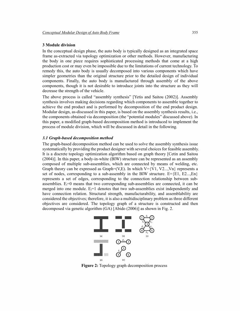
3.1 Graph-based decomposition method The graph-based decomposition method can be used to solve the assembly synthesis issue systematically by providing the product designer with several choices for feasible assembly. It is a discrete topology optimization algorithm based on graph theory [Cetin and Saitou (2004)]. In this paper, a body-in-white (BIW) structure can be represented as an assembly composed of multiple sub-assemblies, which are connected by means of welding, etc. Graph theory can be expressed as Graph=(V,E). In which V={V1, V2...,Vn} represents a set of nodes, corresponding to a sub-assembly in the BIW structure. E={E1, E2...,En} represents a set of edges, corresponding to the connection relationship between sub-assemblies. Ei=0 means that two corresponding sub-assemblies are connected, it can be merged into one module. Ei=1 denotes that two sub-assemblies exist independently and have connection relation. Structural strength, manufacturability, and assemblability are considered the objectives; therefore, it is also a multidisciplinary problem as three different objectives are considered. The topology graph of a structure is constructed and then decomposed via genetic algorithm (GA) [Abido (2006)] as shown in Fig. 2.
Figure 2: Topology graph decomposition process

356 CMES, vol.122, no.1, pp.351-376, 2020
3.2 Modified graph-based decomposition method Though the graph-based decomposition method is effective for assembly synthesis, the actual optimization process is still very time-consuming when dealing with sophisticated structures. A modified graph-based decomposition algorithm that optimally decomposes the assembly body structure into a set of components was presented in a previous paper by the authors of the present paper [Hou, Hou, Xu et al. (2015)]. In contrast with the original version, invalid decomposition modes which may account for more than 50% of all possible ones are excluded to dramatically reduce the computational overhead. The invalid decomposition modes mentioned above generally do not conform to practical engineering standards, as shown in Fig. 3. Fig. 3(b) shows the initial topology graph of the original structure shown in Fig. 3(a). A final decomposition mode is shown in Fig. 3(c). According to this mode, there will be a welding line between units 7 and 9 indicating that this subcomponent should be sheared and then welded between units 7 and 9. Obviously, this is an invalid decomposition mode as it is not permitted in an actual manufacturing process. To resolve this defect, an additional constraint called the “characteristic retaining strategy” is introduced for each decomposition mode; this maintains the appropriate interconnections among subcomponents identical to the original topology graph. After the correction of this constraint, E11 between vertex 7 and 9 is retained. Fig. 3(d) shows the final decomposition mode after the modification which conforms to practical engineering standards. What’s more, a large number of invalid decomposition modes won’t be analyzed, thus the computational overhead is reduced.
Figure 3: Characteristic retaining strategy
The additional constraint is expressed as follows:
x)E),(Graph(V,GRAPHFIXEDxfixed = (1)
where Graph(V,E) represents the information in initial topology graph and x is a splitting vector, i.e., a decomposition mode of the graph. Through this constraint function GRAPHFIXED( ), a correctional xfixed is returned to guarantee the rationality of the corresponding decomposition and truncate the computation time.

Conceptual Modular Design of Auto Body Frame 357
In our program implementation, an adjacency matrix was introduced to represent the original topology graph and decomposition in MATLAB. As shown in Fig. 4, the relevant zeros in the decomposition adjacent matrix (b) are transformed into ones via the modification described above according to the original topology graph shown in (a), and (c) which represents the final decomposition is achieved.
Figure 4: Implementation of the modification
3.3 Process of potential module division A reasonable decomposition mode can be obtained naturally by the modified graph-based decomposition algorithm. The body-side is shown in Fig. 4 as an example. It is still necessary, however, to effectively identify the optimal mode among thousands of solutions. Three objectives which can evaluate the merit of each decomposition mode are discussed below. 1) Structural stiffness fstiffness. This objective may be equivalent to the max-displacement of the structure in stiffness analysis. After adding a minus, the fstiffness can be formulated as follows: 𝒇𝒇𝐬𝐬𝐬𝐬𝐬𝐬𝐬𝐬𝐬𝐬𝐬𝐬𝐬𝐬𝐬𝐬𝐬𝐬 = −𝑚𝑚𝑚𝑚𝑚𝑚𝑚𝑚𝑚𝑚𝑚𝑚𝑚𝑚𝑚𝑚𝑚𝑚𝑚𝑚𝑚𝑚𝑚𝑚𝑚𝑚𝑚𝑚𝑚𝑚(𝑮𝑮𝑮𝑮𝑮𝑮𝑮𝑮𝑮𝑮(𝒙𝒙),𝒀𝒀) (2) where vector Y denotes design variables corresponding to the properties of joints, such as welding and adhesive bonding. 2) Manufacturability fmanu. The total expense of all the subcomponents can be used to measure the manufacturability of the subcomponents obtained from the decomposition. Sheet metal stamping is the main manufacturing mode in car factories, so mold cost forms the manufacturability index. The area of the outside envelope rectangle can be used to evaluate this index in the conceptual phase:
𝒇𝒇𝒎𝒎𝑮𝑮𝒎𝒎𝒎𝒎 = −∑ 𝑀𝑀𝑀𝑀𝑚𝑚𝑚𝑚𝑀𝑀𝑀𝑀𝑚𝑚𝑚𝑚 �𝐴𝐴𝐴𝐴𝑚𝑚𝑚𝑚 �𝑀𝑀𝑀𝑀𝑚𝑚𝑚𝑚�𝒊𝒊,𝑮𝑮𝑮𝑮𝑮𝑮𝑮𝑮𝑮𝑮(𝒙𝒙)���𝑛𝑛𝑖𝑖=1 (3)
where Comp( ) is the computed assembly graph and Area( ) is the outside envelope area of the subcomponent.

358 CMES, vol.122, no.1, pp.351-376, 2020
3) Assemblability fassem. Welding is the primary production method in automotive component assembly lines, so the number of welding spots can be used to evaluate fassem: 𝒇𝒇𝑎𝑎𝑎𝑎𝑎𝑎𝑎𝑎𝑎𝑎 = −∑ 𝑊𝑊𝑚𝑚𝑚𝑚𝑚𝑚𝑚𝑚𝑚𝑚𝑊𝑊𝑊𝑊𝑚𝑚𝑀𝑀𝑚𝑚((𝑮𝑮𝑮𝑮𝑮𝑮𝑮𝑮𝑮𝑮(𝒙𝒙),𝒀𝒀))𝑛𝑛
𝑖𝑖=1 (4) Finally, the optimization model is formulated as follows: min { fstiffness, fmanu, fassem} s.t. x∈{0,1} and xfixed=GRAPHFIXED(Graph(V,E),x) (5) Y=(y1, y2,…, yE), yi∈FBEAM The above is a nonlinear multi-objective problem. In this study, NSGA-II was utilized to solve the problem and subsequently obtain a Pareto set.
3.4 Optimal decomposition selection Once the Pareto set is ready, the engineer must select an exact result from the set as the best possible solution. According to the literature, fuzzy set theory is applicable here. For non-dominated solution k, the corresponding dominant function μk is defined as follows:
∑ ∑∑= =
==p obj
obj
M
j
N
ij
i
N
ikik
1 1
1
µ
µµ (6)
We use a membership function 𝜇𝜇𝑖𝑖𝑘𝑘 represent the ith objective function value of solution k in the Pareto-optimal set Fi , as shown in Eq. (7).
max
max
minminmax
max
min
,0
,
,1
i
ii
iiii
ii
ii
ki F
FF
FFFFFF
FF
≥
<<−−
≤
=µ (7)
where Fimin is the minimum value of the ith objective function in the Pareto set and Fi
max is the maximum. For solutions in a Pareto set, a maximum μk represents the best solution; thus, engineers can make selections according to the rank of μk. Though a nominally best solution is chosen in the end, it cannot satisfy diverse requirements in engineering because the varying degrees of importance of any objective must be taken into consideration in various situations. Furthermore, there is no equilibrium among the objectives-a solution may be chosen simply due to a single extremely high objective value though the others are ineffective. To address the first issue, a weighting factor 𝜈𝜈𝑖𝑖 is introduced for each objective which can be determined by the engineers according to the degree of importance of the objective. To overcome the second defect, an additional objective σ is proposed which represents the variance of all objectives, as shown in Eq. (8).
∑ ∑=
=
−=
Nobj
iobj
Nobj
ikik
ik N1
2
1µ
µσ (8)
Via the improvements above, the final formulation of μk is as follows:

Conceptual Modular Design of Auto Body Frame 359
∑ ∑∑= =
=
+
+=
pM
j
Nobj
ijj
ii
Nobj
ikiik
Modvv
vv
1 1
1
][ σσ
σσ
µµ
µµµ (9)
4 Module slection As the car types in a product family or a platform are generally developed from the same auto body structure design, therefore they share essentially the same basic construction apart from the fact that each may have a few unique characteristics locally. Thus via the techniques discussed in the last section, we can get the optimal decomposition mode of the original auto body and regard it as the final decomposition mode of all car types for compromise. Though it may be not the optimal one for some car types, we found in our computation that loss of the three objectives is tiny enough to be ignored. Now we have got the potential modules, i.e., the components produced by the optimal assembly mode. Before the final module selection process, we have to optimize the thicknesses of each manufacturing element in all car types simultaneously. This optimization should not only try to maximize the commonality of modules but also minimize the loss of performance of all car types. To overcome this sophisticated optimization problem which involves large amounts of coupling variables and more than one objectives, we resorted to Collaborative Optimization (CO) methodology and developed an effective optimization process with its consistency constraint function.
4.1 Collaborative optimization The design process of complex mechanical systems is growing increasingly sophisticated alongside rapid advancements in science and technology. The process, including when applied to automobiles, often necessitates relevant knowledge of more than one discipline. Multidisciplinary Design Optimization (MDO) was first proposed in the 1990s in response to this problem. It takes the coupling and restricting effects among different disciplines into full consideration. Numerous MDO methods have been applied to engineering successfully, including collaborative optimization, target cascading, and concurrent subspace optimization [Fellini, Kokkolaras and Papalambros (2006); Rebentisch, Schuh, Rudolf et al. (2016); Bayrak, Collopy, Papalambros et al. (2018)]. Collaborative Optimization (CO) is a well-suited method for large-scale MDO problems. It is a design architecture that preserves traditional disciplinary groupings by allowing the parallel development of designs, and has been widely used in many fields since being first proposed by Kroo. CO decomposes a complex MDO problem into an upper system level and several lower sub-systems. Each sub-system represents a subsidiary discipline and there are discrepancies between them. The top level is a system optimizer and it optimizes these discrepancies to satisfy the interdisciplinary coupling constraints. In other words, These sub-systems are optimized in the optimization process to meet their unique constraints. The following equation is a standard optimization formula. f(x) represents the objective function, xi represents optimization variable, gu(x) represents equality constraint, and hv(x) represents inequality constraint. The optimization variable sometimes has a scope comprised of upper limit xu and lower limit xl.

360 CMES, vol.122, no.1, pp.351-376, 2020
min𝑓𝑓(𝑚𝑚𝑖𝑖) s. t.𝑊𝑊𝑢𝑢(𝑚𝑚𝑖𝑖) ≤ 0,𝑢𝑢 = 1,2, … ,𝑚𝑚 ℎ𝑣𝑣(𝑚𝑚𝑖𝑖) = 0,𝑣𝑣 = 1,2, … ,𝑚𝑚 𝑚𝑚𝑖𝑖𝑙𝑙 ≤ 𝑚𝑚𝑖𝑖 ≤ 𝑚𝑚𝑖𝑖𝑢𝑢
(10)
gu(x) and hv(x) are divided into several parts each representing the constraints in a corresponding subsidiary discipline. Therefore, Eq. (10) can be written in CO form as follows:
Figure 5: Collaborative optimization structure
As shown in Fig. 5, the whole system consists of N subsystems. 𝐽𝐽𝑖𝑖(z,p) represents system-level compatibility constraint. It is usually relaxed to positive minimum value ξ (𝐽𝐽𝑖𝑖(z,p)≤ξ) because 𝐽𝐽𝑖𝑖(z,p)=0 cannot always be satisfied. Subscript i and j stands for sub-disciplines and variables, and 𝑚𝑚𝑖𝑖𝑖𝑖∗ is the optimal solution obtained from sub-disciplines. At the system level, the optimizer is used to ensure interdisciplinary compatibility of the overall variables and minimize the objective function. At the sub-system level, design variable optimization is acceptable only when related constraints are satisfied. This structure is an integral design involving the objectives of various disciplines. While satisfying local constraints, it minimizes the conflicts between the subsidiary discipline level and the system level. Fig. 6 is the form summary of CO flowchart.
Figure 6: CO framework

Conceptual Modular Design of Auto Body Frame 361
4.2 Method based on consistency constraint function When optimizing a product family which consists of several vehicle types, the different vehicles can be regarded as sub-disciplines in CO. The shared variables should meet the requirement 𝐽𝐽𝑖𝑖(z,p)=0 (or at least 𝐽𝐽𝑖𝑖(z,p)≤ξ), which is quite difficult to satisfy in practice. In this study, 𝐽𝐽𝑖𝑖(𝑧𝑧,𝑚𝑚) served as an objective function instead of a constraint function. The optimization problem thus involved securing sufficient variables to make 𝐽𝐽𝑖𝑖(𝑧𝑧,𝑚𝑚) ≤ ξ and keep the ξ value small. The consistency constraint function-based method is illustrated in Fig. 8. In this algorithm, the optimization at system level is a multi-objective unconstrained optimization which minimizes the corresponding 𝐽𝐽𝑖𝑖(z,p) of each optimized design variable obtained from the subsystems. If the result is sufficiently small, the optimized variable can be a shared variable in the platform. The subsystem-level optimizations are usually constrained optimizations which maximize the performance of each car type. The optimal values of design variables are delivered back and forth between the system level and subsystem levels before the iteration ends. In Fig. 7, 𝑚𝑚𝑖𝑖𝑖𝑖∗ is the optimal solution obtained from the sub-disciplines, 𝑧𝑧𝑖𝑖𝑖𝑖∗ is the optimal solution obtained from system optimization, and 𝑚𝑚𝑖𝑖𝑖𝑖0 is the initial iterative value at the subsidiary discipline level which is identical to 𝑧𝑧𝑖𝑖𝑖𝑖∗ . Via the modification above, a good balance between the commonality of the platform and performance of each car type can be reached. That is to say, the performance loss due to the introduction of modules is minimized. What’s more, the calculation becomes much easier to converge with this modification.
Figure 7: Modified method based on consistency constraint function
4.3 Module selection process Any part of the auto body can be optimized via the proposed method, and we take body-side structure of the BIW as an example here. Fig. 8 shows an exploded view of a real body-side, which is comprised of unbroken “basic structures” and scattered “reinforcements” (the integrated body-side outer panel excluded). The “basic structure” here refers to body-side inner and outer panels of the beams, while the “reinforcements” include the pillar reinforcement panel, rear fender liner, and other components. It is necessary to subdivide the modular design into the design of basic structures and the design of reinforcements to ensure a fully exhaustive modular design.

362 CMES, vol.122, no.1, pp.351-376, 2020
Figure 8: Exploded view of body-side structure
For the sake of simplicity, beams are usually used to approximate the skeleton structure of the BIW in the conceptual design phase. However, a certain level of accuracy must be ensured simultaneously to obtain correct mechanical analysis results. The sectional properties (e.g., area, centroid coordinates, and inertial moment) are present in the finite element analysis formulas, so the actual sections with complex outlines in the BIW can be substituted by simple sections on the condition that their sectional properties are identical. In this study, thin-walled rectangular sections were adopted as shown in Fig. 9. The simplified section outlines are similar to the original sections to a large extent in many beams, thus setting the appropriate wall thickness can readily ensure identical sectional properties.
Figure 9: Thin-walled rectangular beams
As the simplified model for potential modules, a thin-walled beam of the conceptual auto body and relevant sectional dimensions are illustrated in Fig. 10. In this paper, the longitudinal dimensions a and b are called “manufacturing dimensions”; they contribute substantially to inertia moment and other sectional properties. The thickness dimensions T and t in two perpendicular directions are called “scantling dimensions”. Basic structures are considered to be manufactured according to the manufacturing dimensions of potential modules in the

Conceptual Modular Design of Auto Body Frame 363
module selection. They account for the major part of production cost, thus the scantling dimensions of basic structure modules should be maximized to lower the cost. However, the reinforcements are usually a complement to basic structures, which are produced according to the minimum manufacturing element and used to strengthen the whole body. During the modular design of the conceptual auto body, the basic structure of the potential module can be shared on the condition that the boundary dimensions and manufacturing dimensions (a and b) are uniform among different car types. The reinforcement is shared if the scantling dimensions (T and t) of the reinforcements are identical in addition to the boundary dimensions and manufacturing dimensions (a and b).
Figure 10: Thin-walled beam of conceptual BIW
With a potential module composed of hinge pillar and part of the rocker serving as an example, Fig. 11 illustrates the dimensional relationship among the three structures discussed above (potential modules, basic structures, reinforcements). The first subscript of the dimensions stands for the number of corresponding manufacture elements, while the second one, B or R, represents the basic structure and reinforcement, respectively. The basic structure and reinforcement are both extracted from the potential module, with thickness dimensions that must satisfy the following equation:
3,2,1,, ==+=+ itttTTT iiRiBiiRiB (11)
Figure 11: Decomposition of potential module

364 CMES, vol.122, no.1, pp.351-376, 2020
Figure 12: Module selection method (TRB considered)

Conceptual Modular Design of Auto Body Frame 365
Figure 13: Module selection method (TRB not considered)

366 CMES, vol.122, no.1, pp.351-376, 2020
The modified graph-based decomposition and consistency constraint function methods yield the optimal division mode and structural dimensions of each manufacture element, respectively, in the conceptual design phase. The shared basic structures and reinforcements can be obtained via an exhaustive contrastive analysis of the two sets of optimal results. During the module selection process, shared elements in the basic structure are prioritized because the cost of a basic structure is much higher than that of a reinforcement. The selection process can be boiled down to two steps: 1) Optimization calculation of the decomposition mode and dimensions of the body-side via modified graph-based decomposition and consistency constraint function methods; 2) Use the decomposition mode as a comparative basis to identify the distribution and commonality of basic structures and reinforcements by analyzing the dimensions in four directions of the potential modules one-by-one. The potential module shown in Fig. 12 is used below as an example of the detailed implementation of this method. The commonality of the manufacturing dimensions (a and b) among all of the variants in a product family are discussed separately. The module selection process is also applied to best-case, average, and worst-case scenarios as discussed below.
4.3.1 Best-case result of dimension optimization The best-case dimension optimization result is one in which the manufacturing dimensions (a and b) of all the three manufacture elements are universal among all car types. The basic structure in this potential module is sure to be shared, as shown in Fig. 13, where the universal manufacturing dimensions are highlighted in blue. The optimal dimensions satisfy Eq. (12) in this case. The equal sign can be relaxed to a certain dimensional tolerance determined by engineers in an actual design process, however. The single subscript of the manufacturing dimensions (a and b) stands for the number of corresponding manufacture elements. As for the scantling dimensions (T and t), the first subscript stands for the car type to which it belongs and the second subscript is equivalent to the manufacturing dimensions.
𝑚𝑚Ⅰ𝑖𝑖 = 𝑚𝑚Ⅱ𝑖𝑖 = ⋯ = 𝑚𝑚𝑁𝑁𝑖𝑖 = 𝑚𝑚𝑖𝑖,
𝑏𝑏Ⅰ𝑖𝑖 = 𝑏𝑏Ⅱ𝑖𝑖 = ⋯ = 𝑏𝑏𝑁𝑁𝑖𝑖 = 𝑏𝑏𝑖𝑖,
𝑚𝑚 = 1,2,3
(12)
The basic structure is given priority in regards to shared components, so the next task is to decide the thickness dimensions (T and t) of the shared basic structure. Tailor Rolling Blanks (TRB) and Tailor Welded Blanks (TWB) are advanced technologies which allow continuous variation of the sectional thickness in an unbroken part [Kinsey (2011)]. There are two cases to consider when determining the thickness dimensions. 1) Advanced technologies are adopted in auto manufacture, therefore, the three manufacture elements in the shared basic structure may have different thicknesses as-determined by Eq. (13). This method ensures that the thicknesses of the shared basic structures are all maximized in accordance with the priority they are given.

Conceptual Modular Design of Auto Body Frame 367
𝑇𝑇1𝑎𝑎𝑖𝑖𝑛𝑛 = min �𝑇𝑇Ⅰ1,𝑇𝑇Ⅱ1, … ,𝑇𝑇𝑁𝑁1� , 𝑚𝑚1𝑎𝑎𝑖𝑖𝑛𝑛 = min {𝑚𝑚Ⅰ1, 𝑚𝑚Ⅱ1, … , 𝑚𝑚𝑁𝑁1}
𝑇𝑇2𝑎𝑎𝑖𝑖𝑛𝑛 = min �𝑇𝑇Ⅰ2,𝑇𝑇Ⅱ2, … ,𝑇𝑇𝑁𝑁2� , 𝑚𝑚2𝑎𝑎𝑖𝑖𝑛𝑛 = min {𝑚𝑚Ⅰ2, 𝑚𝑚Ⅱ2, … , 𝑚𝑚𝑁𝑁2}
𝑇𝑇3𝑎𝑎𝑖𝑖𝑛𝑛 = min �𝑇𝑇Ⅰ3,𝑇𝑇Ⅱ3, … ,𝑇𝑇𝑁𝑁3� , 𝑚𝑚3𝑎𝑎𝑖𝑖𝑛𝑛 = min {𝑚𝑚Ⅰ3, 𝑚𝑚Ⅱ3, … , 𝑚𝑚𝑁𝑁3}
(13)
The thicknesses 𝑇𝑇1𝑎𝑎𝑖𝑖𝑛𝑛,𝑇𝑇2𝑎𝑎𝑖𝑖𝑛𝑛,𝑇𝑇3𝑎𝑎𝑖𝑖𝑛𝑛, 𝑚𝑚1𝑎𝑎𝑖𝑖𝑛𝑛, 𝑚𝑚2𝑎𝑎𝑖𝑖𝑛𝑛 , and 𝑚𝑚3𝑎𝑎𝑖𝑖𝑛𝑛 are shown in Fig. 13 for each car type corresponding to Basic StructureⅠ, Basic Structure Ⅱ, and Basic Structure Ⅲ. The basic structures of the three car types have exactly the same dimensions, including a, b, T, and t in each manufacture element, i.e., the basic structure is totally shared. The next task is to determine the thickness dimensions (T and t) of the reinforcements in each manufacture element where the shared basic structure is excluded. The computational formulas for each reinforcement manufacture element, Reinforcement Ⅰ, Reinforcement Ⅱ, and Reinforcement Ⅲ are shown in Fig. 13. For example, the thickness in the T direction for manufacture element 1 in Reinforcement Ⅰ is calculated by 𝑇𝑇Ⅰ1 − 𝑇𝑇1𝑎𝑎𝑖𝑖𝑛𝑛 and the thickness in t direction is 𝑚𝑚Ⅰ1 − 𝑚𝑚1𝑎𝑎𝑖𝑖𝑛𝑛. In selecting reinforcement modules, the three manufacture elements should be investigated individually. Only if the two thicknesses mentioned above are identical in more than two car types is the corresponding reinforcement in this manufacture element shared among them; otherwise, the corresponding reinforcement is not a shared module at all. Consider manufacture element 1, the hinge pillar, as an example. If its two thicknesses satisfy Eq. (14) for some car types, say, they are identical between only car types Ⅰ and Ⅱ, then the corresponding Reinforcement Ⅰ and Ⅱ are partially shared modules between the first two car types, while the corresponding reinforcement in other car types are all unique modules which must be manufactured separately.
𝑇𝑇Ⅰ1 − 𝑇𝑇1𝑎𝑎𝑖𝑖𝑛𝑛 = 𝑇𝑇Ⅱ1 − 𝑇𝑇1𝑎𝑎𝑖𝑖𝑛𝑛 = 𝑇𝑇, 𝑏𝑏𝑢𝑢𝑚𝑚 𝑇𝑇 ≠ 𝑇𝑇Ⅲ1 − 𝑇𝑇1𝑎𝑎𝑖𝑖𝑛𝑛 ≠ ⋯
≠ 𝑇𝑇𝑁𝑁1 − 𝑇𝑇1𝑎𝑎𝑖𝑖𝑛𝑛
𝑚𝑚Ⅰ1 − 𝑚𝑚1𝑎𝑎𝑖𝑖𝑛𝑛 = 𝑚𝑚Ⅱ1 − 𝑚𝑚1𝑎𝑎𝑖𝑖𝑛𝑛 = 𝑚𝑚, 𝑏𝑏𝑢𝑢𝑚𝑚 𝑚𝑚 ≠ 𝑚𝑚Ⅲ1 − 𝑚𝑚1𝑎𝑎𝑖𝑖𝑛𝑛 ≠ ⋯ ≠ 𝑚𝑚𝑁𝑁1 − 𝑚𝑚1𝑎𝑎𝑖𝑖𝑛𝑛
(14)
Similar to the basic structure selection process, the equal sign can be relaxed to a certain dimensional tolerance determined by engineers for the sake of an actual design. It is important to note that if the two thicknesses of a reinforcement are both zero, then there is no reinforcement corresponding to the manufacture element. For instance, if Eq. (15) is satisfied, then the Reinforcement corresponding to manufacture element 1 in car typeⅠ does not exist.
𝑇𝑇Ⅰ1 − 𝑇𝑇1𝑎𝑎𝑖𝑖𝑛𝑛 = 𝑚𝑚Ⅰ1 − 𝑚𝑚1𝑎𝑎𝑖𝑖𝑛𝑛 = 0 (15)
2) Advanced technologies are undesirable as they come at a very high manufacture cost. To keep costs reasonable, the three manufacture elements in a shared basic structure should have same thicknesses as-determined by Eq. (16). These dimensions and the process of module selection are shown in Fig. 14.

368 CMES, vol.122, no.1, pp.351-376, 2020
𝑇𝑇𝑎𝑎𝑖𝑖𝑛𝑛 = 𝑚𝑚𝑚𝑚𝑚𝑚 �𝑇𝑇Ⅰ1,𝑇𝑇Ⅰ2,𝑇𝑇Ⅰ3,𝑇𝑇Ⅱ1,𝑇𝑇Ⅱ2,𝑇𝑇Ⅱ3, … ,𝑇𝑇𝑁𝑁1,𝑇𝑇𝑁𝑁2,𝑇𝑇𝑁𝑁3�
𝑚𝑚𝑎𝑎𝑖𝑖𝑛𝑛 = 𝑚𝑚𝑚𝑚𝑚𝑚 {𝑚𝑚Ⅰ1, 𝑚𝑚Ⅰ2, 𝑚𝑚Ⅰ3, 𝑚𝑚Ⅱ1, 𝑚𝑚Ⅱ2, 𝑚𝑚Ⅱ3, … , 𝑚𝑚𝑁𝑁1, 𝑚𝑚𝑁𝑁2, 𝑚𝑚𝑁𝑁3} (16)
𝑇𝑇𝑎𝑎𝑖𝑖𝑛𝑛 is the minimum of the T dimensions of all manufacture elements in all vehicle types and 𝑚𝑚𝑎𝑎𝑖𝑖𝑛𝑛 is the minimum of the t dimensions. This maximizes the thickness dimensions of the basic structure with the precondition that the basic structure is shared among all car types. Now that screening of basic structures is over, the next task is to determine the thickness dimensions (T and t) of the reinforcements in each manufacture element where the shared basic structure is excluded. The computational formulas are similar to TRB case discussed above and are shown in Fig. 13 beside each manufacture element of the reinforcements. The module selection for reinforcements is similar to that of the first case, so it is not discussed separately here.
4.3.2 Average result of dimension optimization In this case, the manufacturing dimensions (a and b) of all the three manufacture elements are universal in at least two but not all car types. Therefore, the basic structure can only be shared among some of the car types in the product family. Based on the priority given to the basic structure, the shared basic structure is screened only by the method discussed in Section 4.3.1. It is easy to determine the thickness dimensions of the reinforcements in these car types. The reinforcements obtained above merit investigation in regard to other car types which have yet to be addressed. Because there is no shared basic structure among them, it is advisable to maximize the commonality of the reinforcements among these car types to determine the thickness dimensions of the unique basic structures by excluding the reinforcements from the dimension optimization results. It is important to maximize the commonality of the reinforcements by considering their thickness dimensions with remaining car types together as a whole, and then by analyzing the degree of closeness among them. The number of car types in a platform is generally less than ten, so the problem scale is small and easy to solve.
4.3.3 Worst-case result of dimension optimization If the manufacturing dimensions (a and b) of all the three manufacture elements are not universal in any two car types, the dimension optimization result is considered to be the worst-case; the basic structure which accounts for most of the manufacture cost is not shared at all. However, with the assembly units that can be identified as unique modules by outer structure features, most potential modules do not yield this kind of result due to intrinsic structural similarity among different car types in the same platform. In this worst-case scenario, the following measures can be taken to enhance the level of commonality in the basic structure components in a specific potential module. To this effect, some or even all of the basic structures can become universal. The potential module used above is used again here as an example. Assuming that the manufacturing dimensions (a and b) are not universal in any two car types, a new dimension optimization result which

Conceptual Modular Design of Auto Body Frame 369
makes the basic structure universal among all car types can be obtained by modifying the manufacturing dimensions in the computation model according to Eq. (17). Module selection can then be implemented based on the improved optimization result.
𝑚𝑚Ⅰ1 = 𝑚𝑚Ⅱ1 = ⋯ = 𝑚𝑚𝑁𝑁1 = 𝑚𝑚𝑚𝑚𝑚𝑚 {𝑚𝑚Ⅰ1,𝑚𝑚Ⅱ1, … ,𝑚𝑚𝑁𝑁1}
𝑏𝑏Ⅰ1 = 𝑏𝑏Ⅱ1 = ⋯ = 𝑏𝑏𝑁𝑁1 = 𝑚𝑚𝑚𝑚𝑚𝑚 {𝑏𝑏Ⅰ1,𝑏𝑏Ⅱ1, … , 𝑏𝑏𝑁𝑁1}
𝑚𝑚Ⅰ2 = 𝑚𝑚Ⅱ2 = ⋯ = 𝑚𝑚𝑁𝑁2 = 𝑚𝑚𝑚𝑚𝑚𝑚 {𝑚𝑚Ⅰ2,𝑚𝑚Ⅱ2, … ,𝑚𝑚𝑁𝑁2}
𝑏𝑏Ⅰ2 = 𝑏𝑏Ⅱ2 = ⋯ = 𝑏𝑏𝑁𝑁2 = 𝑚𝑚𝑚𝑚𝑚𝑚 {𝑏𝑏Ⅰ2,𝑏𝑏Ⅱ2, … , 𝑏𝑏𝑁𝑁2}
𝑚𝑚Ⅰ3 = 𝑚𝑚Ⅱ3 = ⋯ = 𝑚𝑚𝑁𝑁3 = 𝑚𝑚𝑚𝑚𝑚𝑚 {𝑚𝑚Ⅰ3,𝑚𝑚Ⅱ3, … ,𝑚𝑚𝑁𝑁3}
𝑏𝑏Ⅰ3 = 𝑏𝑏Ⅱ3 = ⋯ = 𝑏𝑏𝑁𝑁3 = 𝑚𝑚𝑚𝑚𝑚𝑚 {𝑏𝑏Ⅰ3,𝑏𝑏Ⅱ3, … , 𝑏𝑏𝑁𝑁3}
(17)
The manufacturing dimensions modified by the above process should be excluded from design variables before recalculation. Moreover, the constraint of mass must be relaxed moderately if no feasible solution can be obtained due to relatively large manufacturing dimensions. Commonality of the basic structure is realized by this modification though the weight of the vehicle may be increased slightly. In practice, the level of the commonality in basic structure and the structural weight can be adjusted by engineers. After all potential modules are addressed, the distribution and commonality of basic structures and reinforcements can finally be obtained using the methodology discussed above. This methodology not only applies to the body-side in the given example, but to other structures which need assembly design and may provide reinforcements in the auto body. As a summary, Fig. 14 shows the detailed flowchart of our methodology discussed above. It can be divided into three main parts in which the assembly optimization part gets the optimal decomposition mode of the original structure design. The dimension optimization part obtains the optimal thicknesses of each manufacturing element with the consideration of not only maximizing their commonality but also minimizing the performance loss of all car types. In the module selection part, modules of basic structure and reinforcement are screening out successively.
Figure 14: Flow chart of modular design based on Hybrid optimization method

370 CMES, vol.122, no.1, pp.351-376, 2020
5 Case study Fig. 15 shows the beam element of the case vehicle:SUV, hatchback, and sedan from the same platform. They come from the same product family. Therefore, they share essentially the same basic construction other than that the SUV’s engine compartment is longer, while the hatchback and sedan’s profiles are lower.
Figure 15: Three models used in case study
5.1 Optimization model As discussed above, the body-side optimization serves as an example here, though any other part of the vehicle can be optimized via the proposed method. In order to get the optimal decomposition mode of the original structure, we built an assembly optimization flow in Isight conducted via modified graph-based decomposition algorithm and NSGA-II. As shown in Fig. 16, Module_Divide component carries out the optimization process with NSGA-II; Manu_Cost component carries out the decomposition process with modified graph-based decomposition algorithm and calculates the manufacture cost. Fem_Model and Stiff_Cal components build a FEA model and calculate the stiffness of the auto body while Ass_Cost component calculates the assembly cost of the decomposition mode. In the process of calculation, the GA population was 100 and 200 generations were carried out; the convergence criterion was target rate below 3%. We used the uniform crossover method with 90% crossover rate, 10% mutation rate, and 50% replacement rate of offspring to the parent generation.
Figure 16: Module division optimization flow in Isight

Conceptual Modular Design of Auto Body Frame 371
Figure 17: Body-side and sectional dimensions
Figure 18: Dimension optimization flow in Isight

372 CMES, vol.122, no.1, pp.351-376, 2020
Pillars A, B, and C of the SUV are longer than hatchback and sedan, whose share the identical body-side. In terms of external manufacturing dimensions, the red parts shown in Fig. 17 are entirely the same among all three car types while the lift parts are only shared between the hatchback and sedan. In other words, only hatchback and sedan can share modules 9, 10, and 11. Each beam has four variables as shown in Fig. 17: T and t scantling dimensions plus a and b manufacturing dimensions. There are 56 variables of 14 beams, comprising the minimum manufacture elements, to select when determining connections between different parts. Fig. 18 shows the dimension optimization flow in Isight conducted via consistency constraint method, where Module_Select is the system-level optimization component and Hatchback, Sedan, and SUV are subsystem-level optimization components corresponding to the three models. FEM parts are scripts for modeling in Hypermesh, and Solve parts are scripts for solving in Optistruct; Stiff parts represent calculations for solving the stiffness. Bending and torsion conditions are both taken into consideration for each car type. In the Initialize part, the optimal values obtained at the system level are passed down to the sub-system level as iterative initial values, i.e., 𝑚𝑚𝑖𝑖𝑖𝑖0 = 𝑧𝑧𝑖𝑖𝑖𝑖∗ as shown in Fig. 7. In the Variance part, 𝐽𝐽𝑖𝑖(𝑚𝑚,𝑚𝑚) = ∑ (𝒙𝒙𝒊𝒊𝒊𝒊 − 𝒒𝒒𝒊𝒊𝒊𝒊)𝟐𝟐 𝒎𝒎𝒊𝒊
𝒊𝒊=𝟏𝟏 is calculated and 𝑞𝑞𝑖𝑖𝑖𝑖 = 𝑚𝑚𝑖𝑖𝑖𝑖∗ is passed up to the Module_Select part. Module_Select minimizes all the 𝐽𝐽𝑖𝑖 (x,p) to yield as many shared variables as possible.
5.2 Results Fig. 19 shows the optimal body-side assembly drawn via the modified graph-based decomposition algorithm. Each color represents an assembly unit which is also a potential module and the manufacture unit of the corresponding basic structure.
Figure 19: Optimal body-side assembly
Figs. 21 and 22 show the final iteration results of manufacturing dimensions (a and b) and scantling dimensions (T and t), where h, s, and v represent the hatchback, sedan, and SUV, respectively. If points are close enough, the optimization results of three different models are very similar. That is, the corresponding variables are shared as shown at point 1b in Fig. 21. On the contrary, if the corresponding points are dispersed, the variables are unique as shown at point 7t1 in Fig. 20. If two points are almost coincident and the third is not as shown at point 6a in Fig. 21, the corresponding variable is a partially shared variable between two models.

Conceptual Modular Design of Auto Body Frame 373
Figure 20: Optimal manufacturing dimensions
Figure 21: Optimal scantling dimensions
We can select shared and partially shared variables through the data shown in Figs. 20 and 21. By applying the methodology described above, the module selection process can be implemented by thorough analysis of dimension optimization results. In regards to manufacturing, the dimensional accuracy tolerance and scantling dimension accuracy is controlled within 5 mm and 0.5 mm respectively. The final screening results are illustrated in Fig. 22, where h-s stands for the modules partially shared by the hatchback and sedan, s-v stands for those shared by the sedan and SUV, and h-v stands for those shared by the hatchback and SUV. Basic structures are marked in gray while reinforcements are marked in other colors. Though the basic structure of component Ⅱ is shared between the hatchback and sedan, the manufacturing dimensions (a and b) are not shared in the first mode of optimization. Concerning the dramatic increase in cost that this represents, plus the fact that the dimensions are still very close between the two car types, measures discussed in Section 4.3.3 were taken to realize commonality in the basic structure. Therefore, Fig. 23 is actually the module selection result of the secondary optimization process.

374 CMES, vol.122, no.1, pp.351-376, 2020
Figure 22: Result of module selection
6 Conclusions Based on our previous work, this paper presented a systematic research methodology of modular design for BIW to maximize commonality of modules while minimizing the loss of performance of all vehicle types in a product family. A novel module selection process of both basic structures and reinforcements is proposed to realize highly exhaustive modular design; priority is given to commonality in basic structure components to minimize production costs. The principal techniques applied in this method include modified graph-based decomposition algorithm, consistency constraint function, and a new module selection method. A case study was conducted to demonstrate that shared modules, partially shared modules, and unique modules of basic structures and reinforcements can be successfully and easily obtained via this method. As a result, production cost is decreased to a large extent because of the commonality of modules. The proposed method can also be applied to not only the body-side but to other structures in auto body which need assembly design and may have reinforcements. The selected modules can provide a good reference for the following stage of detailed design. Acknowledgement: This work was funded by the Innovation Foundation of GAC R&D Center. Support from the organization is gratefully acknowledged.
Conflicts of Interest: The authors declare that they have no conflicts of interest to report regarding the present study.

Conceptual Modular Design of Auto Body Frame 375
References Abido, M. A. (2006): Multiobjective evolutionary algorithms for electric power dispatch problem. IEEE Transactions on Evolutionary Computations, vol. 10, no. 3, pp. 315-329. Agrawal, T.; Sao, A.; Fernandes, K. J.; Tiwari, M. K.; Kim, D. Y. (2013): A hybrid model of component sharing and platform modularity for optimal product family design. International Journal of Production Research, vol. 51, no. 2, pp. 614-625. Bayrak, A. E.; Collopy, A. X.; Papalambros, P. Y.; Epureanu, B. I. (2018): Multiobjective optimization of modular design concepts for a collection of interacting systems. Structural and Multidisciplinary Optimization, vol. 57, no. 1, pp. 83-94. Beiter, P.; Groche, P. (2011): On the development of novel light weight profiles for automotive industries by roll forming of tailor rolled blanks. Key Engineering Materials, vol. 473, pp. 45-52. Cetin, O. L.; Saitou, K. (2004): Decomposition-based assembly synthesis for structural modularity. Journal of Mechanical Design, vol. 126, no. 2, pp. 234-243. Chowdhury, S.; Maldonado, V.; Tong, W.; Messac, A. (2016): New modular product-platform-planning approach to design macroscale reconfigurable unmanned aerial vehicles. Journal of Aircraft, vol. 53, no. 2, pp. 309-322. Fellini, R.; Kokkolaras, M.; Papalambros, P. Y. (2006): Quantitative platform selection in optimal design of product families, with application to automotive engine design. Journal of Engineering Design, vol. 17, no. 5, pp. 429-446. Ferguson, S.; Kasprzak, E.; Lewis, K. (2009): Designing a family of reconfigurable vehicles using multilevel multidisciplinary design optimization. Structural and Multidisciplinary Optimization, vol. 39, no. 2, pp. 171-186. Hou, W. B.; Hou, D. J.; Xu, J. T.; Zhang, W. (2015): A Modified graph-partitioning algorithm for vehicle body assembly structure optimization. Applied Mathematics & Mechanics, vol. 36, no. 5, pp. 515-522. Hou, W. B.; Shan, C. L.; Yu, Y.; Hu, P.; Zhang, H. Z. (2017): Modular platform optimization in conceptual vehicle body design via modified graph-based decomposition algorithm and cost-based priority method. Structural and Multidisciplinary Optimization, vol. 55, no. 6, pp. 2087-2097. Huang, G. X.; Wang, H.; Li, G. Y. (2014): A reanalysis method for local modification and the application in large-scale problems. Structural and Multidisciplinary Optimization, vol. 49, no. 6, pp. 915-930. Kinsey, B. L. (2011): Tailor welded blanks for the automotive industry. Tailor Welded Blanks for Advanced Manufacturing, pp. 164-180. Kokkolaras, M.; Fellini, R.; Kim, H. M.; Michelena, N. F.; Papalambros, P. Y. (2002): Extension of the target cascading formulation to the design of product families. Structural and Multidisciplinary Optimization, vol. 24, no. 4, pp. 293-301. Konosu, H. (2002): Skill-assist: helping human workers with automobile modular component assembly (No. 2002-01-0126). SAE Technical Paper.

376 CMES, vol.122, no.1, pp.351-376, 2020
Lampon, J. F.; Cabanelas, P. (2014): The modular platform strategy: a new revolution in the production’s organization in the automobile sector? UCJC Business and Society Review, no. 42, pp. 14-31. Lampón, J.; Cabanelas, P.; Benito, J. G. (2015): The impact of implementation of a modular platform strategy in automobile manufacturing networks. Governance and Economics Research Network Working Paper B, no. 2. Lewis, P. K.; Mattson, C. A. (2013): An optimization-based method for designing modular systems that traverse dynamic s-pareto frontiers. Structural and Multidisciplinary Optimization, vol. 48, no. 4, pp. 747-762. Li, C.; Kim, I. Y.; Jeswiet, J. (2015): Conceptual and detailed design of an automotive engine cradle by using topology, shape, and size optimization. Structural and Multidisciplinary Optimization, vol. 51, no. 2, pp. 547-564. Muffatto, M.; Roveda, M. (2000): Developing product platforms: analysis of the development process. Technovation, vol. 20, no. 11, pp. 617-630. Rebentisch, E.; Schuh, G.; Rudolf, S., Breunig, S.; Brakemeier, C. (2016): Technology assessment for modular product platforms with fuzzy numbers. Procedia Cirp, vol. 50, pp. 601-606. Shan, Q.; Chen, Y. (2009): Product modular platform design using SA_PSO. 2nd IEEE International Conference on Computer Science and Information Technology, pp. 176-179. Simpson, T. W.; Marion, T.; De Weck, O.; Kokkolaras, M. (2008): Platform-based design and development: current trends and needs in industry. ASME 2006 International Design Engineering Technical Conferences and Computers and Information in Engineering Conference, pp. 801-810. American Society of Mechanical Engineers Digital Collection. Seiffert, U. W.; Braess, H. H. (2005): Handbook of automotive engineering. SAE Technical Paper, vol. 312. Torstenfelt, B.; Klarbring, A. (2007): Conceptual optimal design of modular car product families using simultaneous size, shape and topology optimization. Finite Elements in Analysis and Design, vol. 43, no. 14, pp. 1050-1061. Wang, H.; Zeng, Y.; Li, E.; Huang, G. X.; Gao, G. Q. et al. (2016): “Seen Is Solution” a CAD/CAE integrated parallel reanalysis design system. Computer Methods in Applied Mechanics and Engineering, vol. 299, pp. 187-214. Yetis, F. A.; Saitou, K. (2002): Decomposition-based assembly synthesis based on structural considerations. Journal of Mechanical Design, vol. 124, no. 4, pp. 593-601. Zuo, W.; Yu, J.; Saitou, K. (2016): Stress sensitivity analysis and optimization of automobile body frame consisting of rectangular tubes. International Journal of Automotive Technology, vol. 17, no. 5, pp. 843-851.


