Conceptual Design on N16 Decay Chamber for Modified TRIGA ...
6
Jurnal Pengembangan Energi Nuklir Vol. 20, No. 1, (2018) 25-30 25 Jurnal Pengembangan Energi Nuklir Laman Jurnal: jurnal.batan.go.id/index.php/jpen Conceptual Design on N 16 Decay Chamber for Modified TRIGA-2000 with Plate-Type Fuel Sukmanto Dibyo 1 , Surian Pinem 1 , V.I.S.Wardhani 2 1 Center for Nuclear Reactor Technology and Safety, National Nuclear Energy Agency of Indonesia (BATAN), Kawasan Puspiptek Gd. 80 Setu, Tangerang Selatan – Banten, Indonesia 2 Center for Science and Applied Nuclear Technology, National Nuclear Energy Agency of Indonesia (BATAN), Bandung, Indonesia ARTICLE INFORMATION ABSTRACT Article History: Received: 27 April 2018 Received in revised form: 24 July 2018 Accepted: 07 August 2018 CONCEPTUAL DESIGN ON N 16 DECAY CHAMBER FOR MODIFIED TRIGA-2000 WITH PLATE-TYPE FUEL. The TRIGA-2000 is a research reactor in bandung that will be modified using plate-type fuel. The reactor core cooling system is changed from the natural convection cooling mode to the forced convection mode. The purpose of the study is to assess the conceptual design for the decay chamber of N 16 nuclide in the primary cooling system of the reactor. In this design, the hold-up system decays the nuclide of N 16 resulted from neutron activation product. In the period of 50 seconds, the activity of N 16 (T1/2= 7.13 seconds) decays 7 time from half life to low level. The cube shape of decay chamber is provided a plate with 4 hollows and facility to flush the cavitation bubbles. The decay chamber, which is submerged into the bulk shielding as located outside of the reactor pool. The conceptual design uses the Fluent software compared with the analytical estimation for flow velocity in the decay chamber. The result shows a good agreement range with the analytical estimations. The uniform flow profile can be obtained at the velocity of about 0.4 m/s. Water flow life time of 50 seconds in the decay chamber with the capacity of 3.5 m 3 is able to decay the N 16 nuclide to low level. This decay chamber is expected to contribute in completing the design of reactor primary coolant system using the forced convection mode. ABSTRAK DESAIN KONSEPTUAL RUANG TUNDA N 16 UNTUK TRIGA-2000 MODIFIKASI ELEMEN BAKAR TIPE PLAT. TRIGA-2000 adalah reaktor riset di bandung yang direncanakan untuk dimodifikasi menggunakan bahan bakar tipe pelat. Sistem pendingin teras reaktor diubah dari moda pendinginan konveksi alam ke konveksi paksa. Penelitian ini bertujuan mengkaji desain konseptual ruang penunda nuklida N 16 pada sistem pendingin primer reaktor. Dalam desain ini, sistem peluruhan (sistem hold-up) akan meluruhkan nuklida N 16 yang dihasilkan dari produk aktivasi neutron. Dalam perioda 50 detik, aktivitas N 16 (T1/2 = 7,13 detik) meluruhkan 7 kali dari waktu paruh ke level rendah. Bentuk ruang tunda adalah kubus yang dilengkapi pelat dengan 4 lubang dan fasilitas flushing untuk membuang gelembung kavitasi. Ruang tunda diletakkan pada bulk shielding reaktor yang terletak di luar kolam reaktor. Desain konseptual ini menggunakan perangkat lunak Fluent yang dibandingkan dengan estimasi perhitungan analitis terhadap kecepatan aliran di dalam ruang tunda. Hasilnya menunjukkan adanya kesesuaian antara Fluent dengan estimasi dimana profil alirannya seragam diperoleh pada kecepatan sekitar 0,4 m/s. Waktu tempuh aliran 50 detik melalui kamar tunda dengan kapasitas 3,5 m 3 dapat meluruhkan nuklida N 16 ke level yang rendah. Desain ruang tunda ini diharapkan dapat memberikan kontribusi dalam melengkapi desain pendingin primer reaktor menggunakan moda konveksi paksa. Katakunci: Ruang tunda N 16 , konveksi paksa, kecepatan aliran, TRIGA-2000, FLUENT Keywords: Decay chamber of N 16 Forced convection Flow velocity TRIGA-2000 FLUENT software © 2018 Jurnal Pengembangan Energi Nuklir. All rights reserved 1. INTRODUCTION The TRIGA-2000 Bandung is one of the research reactor in Indonesia that has been operating for more than 50 years. This pool type reactor uses the standard TRIGA fuel element. Its has been upgraded and safely operated at the power of 2000 kWth[1]. However, its operation depends on the fuel supplied by General Atomics (GA). Since GA no longer produces the TRIGA reactor fuel, and in regard with the production of domestic fuel elements, the replacement of the TRIGA reactor core from fuel cylinder to the fuel plate is planned[2,3]. The innovation to modify the reactor core using plate-type fuel has been studied which PT INUKI (Industri Nuklir Indonesia) successfully produces the plate-type fuel to be used for RSG-GAS reactor serpong. In the modification, the reactor core cooling system must be changed from natural *Correspondence author. E-mail: [email protected] brought to you by CORE View metadata, citation and similar papers at core.ac.uk provided by Badan Tenaga Nuklir Nasional: Jurnal BATAN
Transcript of Conceptual Design on N16 Decay Chamber for Modified TRIGA ...
Jurnal Pengembangan Energi Nuklir Vol. 20, No. 1, (2018) 25-30
25
Jurnal Pengembangan Energi Nuklir Laman Jurnal: jurnal.batan.go.id/index.php/jpen
Conceptual Design on N16 Decay Chamber for Modified TRIGA-2000 with Plate-Type Fuel
Sukmanto Dibyo1, Surian Pinem1, V.I.S.Wardhani2 1 Center for Nuclear Reactor Technology and Safety, National Nuclear Energy Agency of Indonesia (BATAN), Kawasan Puspiptek Gd. 80 Setu, Tangerang Selatan – Banten, Indonesia 2 Center for Science and Applied Nuclear Technology, National Nuclear Energy Agency of Indonesia (BATAN), Bandung, Indonesia
ARTICLE INFORMATION ABSTRACT
Article History: Received: 27 April 2018 Received in revised form: 24 July 2018 Accepted: 07 August 2018
CONCEPTUAL DESIGN ON N16 DECAY CHAMBER FOR MODIFIED TRIGA-2000 WITH PLATE-TYPE FUEL. The TRIGA-2000 is a research reactor in bandung that will be modified using plate-type fuel. The reactor core cooling system is changed from the natural convection cooling mode to the forced convection mode. The purpose of the study is to assess the conceptual design for the decay chamber of N16 nuclide in the primary cooling system of the reactor. In this design, the hold-up system decays the nuclide of N16 resulted from neutron activation product. In the period of 50 seconds, the activity of N16 (T1/2= 7.13 seconds) decays 7 time from half life to low level. The cube shape of decay chamber is provided a plate with 4 hollows and facility to flush the cavitation bubbles. The decay chamber, which is submerged into the bulk shielding as located outside of the reactor pool. The conceptual design uses the Fluent software compared with the analytical estimation for flow velocity in the decay chamber. The result shows a good agreement range with the analytical estimations. The uniform flow profile can be obtained at the velocity of about 0.4 m/s. Water flow life time of 50 seconds in the decay chamber with the capacity of 3.5 m3 is able to decay the N16 nuclide to low level. This decay chamber is expected to contribute in completing the design of reactor primary coolant system using the forced convection mode.
ABSTRAK
DESAIN KONSEPTUAL RUANG TUNDA N16 UNTUK TRIGA-2000 MODIFIKASI ELEMEN BAKAR TIPE PLAT. TRIGA-2000 adalah reaktor riset di bandung yang direncanakan untuk dimodifikasi menggunakan bahan bakar tipe pelat. Sistem pendingin teras reaktor diubah dari moda pendinginan konveksi alam ke konveksi paksa. Penelitian ini bertujuan mengkaji desain konseptual ruang penunda nuklida N16 pada sistem pendingin primer reaktor. Dalam desain ini, sistem peluruhan (sistem hold-up) akan meluruhkan nuklida N16 yang dihasilkan dari produk aktivasi neutron. Dalam perioda 50 detik, aktivitas N16 (T1/2 = 7,13 detik) meluruhkan 7 kali dari waktu paruh ke level rendah. Bentuk ruang tunda adalah kubus yang dilengkapi pelat dengan 4 lubang dan fasilitas flushing untuk membuang gelembung kavitasi. Ruang tunda diletakkan pada bulk shielding reaktor yang terletak di luar kolam reaktor. Desain konseptual ini menggunakan perangkat lunak Fluent yang dibandingkan dengan estimasi perhitungan analitis terhadap kecepatan aliran di dalam ruang tunda. Hasilnya menunjukkan adanya kesesuaian antara Fluent dengan estimasi dimana profil alirannya seragam diperoleh pada kecepatan sekitar 0,4 m/s. Waktu tempuh aliran 50 detik melalui kamar tunda dengan kapasitas 3,5 m3 dapat meluruhkan nuklida N16 ke level yang rendah. Desain ruang tunda ini diharapkan dapat memberikan kontribusi dalam melengkapi desain pendingin primer reaktor menggunakan moda konveksi paksa. Katakunci: Ruang tunda N16, konveksi paksa, kecepatan aliran, TRIGA-2000, FLUENT
Keywords: Decay chamber of N16 Forced convection Flow velocity TRIGA-2000 FLUENT software
© 2018 Jurnal Pengembangan Energi Nuklir. All rights reserved
1. INTRODUCTION
The TRIGA-2000 Bandung is one of the
research reactor in Indonesia that has been
operating for more than 50 years. This pool
type reactor uses the standard TRIGA fuel
element. Its has been upgraded and safely
operated at the power of 2000 kWth[1].
However, its operation depends on the fuel
supplied by General Atomics (GA). Since GA
no longer produces the TRIGA reactor fuel,
and in regard with the production of domestic
fuel elements, the replacement of the TRIGA
reactor core from fuel cylinder to the fuel
plate is planned[2,3].
The innovation to modify the reactor
core using plate-type fuel has been studied
which PT INUKI (Industri Nuklir Indonesia)
successfully produces the plate-type fuel to
be used for RSG-GAS reactor serpong.
In the modification, the reactor core
cooling system must be changed from natural *Correspondence author. E-mail: [email protected]
brought to you by COREView metadata, citation and similar papers at core.ac.uk
provided by Badan Tenaga Nuklir Nasional: Jurnal BATAN
Sukmanto Dibyo, Surian Pinem, and V.I.S.Wardhani - Jurnal Pengembangan Energi Nuklir Vol. 20, No. 1, (2018) 25-30
26
convection mode to forced convection mode. Currenly, the heat generated is directly
transferred through natural convection
modes and flowed by the coolant pump to the
heat exchanger. In the natural convection
modes, the analysis results of
thermalhydraulic by plate-type fuel which
indicates there is a boiling at reactor power
of 2000 kWth[4]. So, the forced convection
cooling mode should be operated.
In the forced convection, the primary
cooling system is designed to have a
downward flow through the core channel for
normal operation[1,5,6].
The produced fission neutrons in the
reactor core interact with the oxygen atoms
present in the water, resulting in the
radioactive isotope N16 according to the
following reaction:
8 O16 + 0 n1 7 N16 + 1 p1 (1)
In the reaction (Equation 1), N16 produces
high-strength radiation of gamma (γ) rays (6
MeV) and β particles during its decays[7,8].
In case of natural convection, the N16
nuclide decays in the reactor pool, meanwhile,
in the forced convection mode the coolant
goes straight to the outlet of reactor pool, so
during reactor operation the concentration of
N16 at the reactor may causing radiation risk
to the reactor operating personnel[9]. The
additional system required for the forced
convection mode is utilization of N16 decay
(hold-up system) that should decay the
nuclide from neutron activation products. The
coolant water flows through the decay
chamber located outside the reactor pool.
When the reactor in operating, therefore, the
coolant water flows at the mass flow rate of
about 70 kg/s.
In reactor operating condition, the
primary cooling water containing highly
radioactive N16 passes the decay chamber for
a minimum of 50 seconds. In the period of 50
seconds, the activity of N16 (T1/2= 7.13
seconds) decays 7 times of its half life to low
level[10]. Therefore a vessel (hold-up
system) which can decay the activity of N16
nuclides shall be provided in the reactor
primary coolant system.
The purpose of this study is to assess
the conceptually design of decay chamber that
is used to decay the N16 nuclide for the plate-
type fuel modified TRIGA-2000 reactor under
forced convection cooling mode. So, the
activity of N16 decays to low level.
2. METHODOLOGY
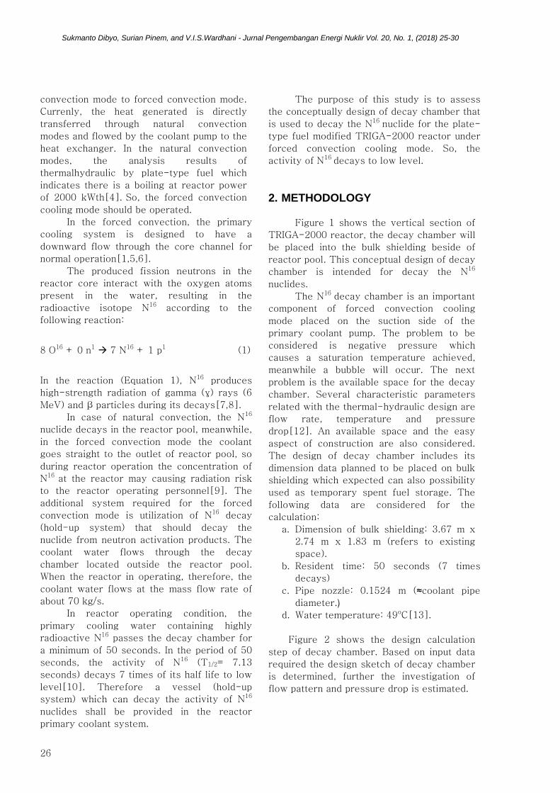
Figure 1 shows the vertical section of
TRIGA-2000 reactor, the decay chamber will
be placed into the bulk shielding beside of
reactor pool. This conceptual design of decay
chamber is intended for decay the N16
nuclides.
The N16 decay chamber is an important
component of forced convection cooling
mode placed on the suction side of the
primary coolant pump. The problem to be
considered is negative pressure which
causes a saturation temperature achieved,
meanwhile a bubble will occur. The next
problem is the available space for the decay
chamber. Several characteristic parameters
related with the thermal-hydraulic design are
flow rate, temperature and pressure
drop[12]. An available space and the easy
aspect of construction are also considered.
The design of decay chamber includes its
dimension data planned to be placed on bulk
shielding which expected can also possibility
used as temporary spent fuel storage. The following data are considered for the
calculation:
a. Dimension of bulk shielding: 3.67 m x
2.74 m x 1.83 m (refers to existing
space).
b. Resident time: 50 seconds (7 times
decays)
c. Pipe nozzle: 0.1524 m (≈coolant pipe
diameter.)
d. Water temperature: 49oC[13].
Figure 2 shows the design calculation
step of decay chamber. Based on input data
required the design sketch of decay chamber
is determined, further the investigation of
flow pattern and pressure drop is estimated.
Sukmanto Dibyo, Surian Pinem, and V.I.S.Wardhani - Jurnal Pengembangan Energi Nuklir Vol. 20, No. 1, (2018) 25-30
27
Figure 1. Vertical Section of TRIGA-2000 Reactor
Bandung[11].
Figure 2. Step of Design Calculation.
Pressure drop (ΔP) is estimated from
equation of fluid flow that flows isothermally,
∆𝑃 = (4. 𝑓𝐿
𝐷+ 𝐾)
𝜌𝑉2
2𝑔 (2)
f is friction factor of turbulence flow, its
determined by explicit correlation as function
of Reynold number[14]:
𝑓 = 0.0014 + 0.125
(𝑅𝑒)0.32 (3)
where,
ΔP: pressure drop, kg/m2
D : equivalent diameter of square channel
K : loss coefficient of turn flow 180o = 1.5
(dimensionless)
V : flow velocity (m/s)
ρ : density (kg/m3)
g : constant gravity (m/s2)
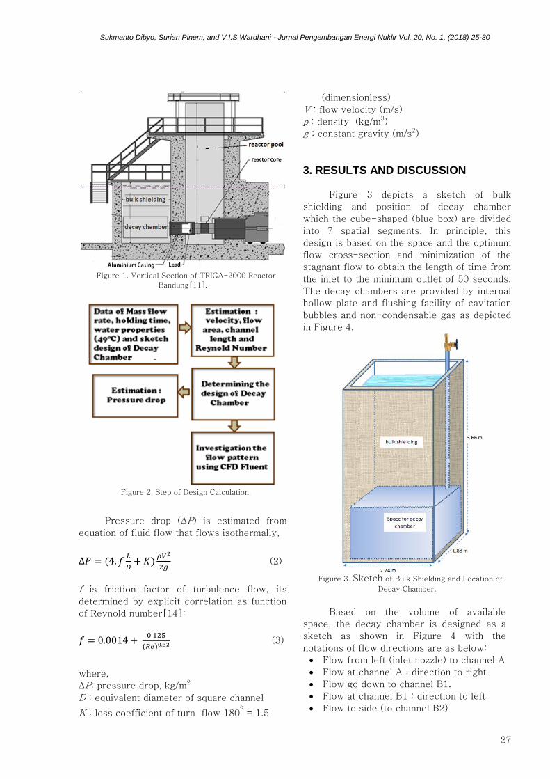
3. RESULTS AND DISCUSSION
Figure 3 depicts a sketch of bulk
shielding and position of decay chamber
which the cube-shaped (blue box) are divided
into 7 spatial segments. In principle, this
design is based on the space and the optimum
flow cross-section and minimization of the
stagnant flow to obtain the length of time from
the inlet to the minimum outlet of 50 seconds.
The decay chambers are provided by internal
hollow plate and flushing facility of cavitation
bubbles and non-condensable gas as depicted
in Figure 4.
Figure 3. Sketch of Bulk Shielding and Location of
Decay Chamber.
Based on the volume of available
space, the decay chamber is designed as a
sketch as shown in Figure 4 with the
notations of flow directions are as below:
• Flow from left (inlet nozzle) to channel A
• Flow at channel A : direction to right
• Flow go down to channel B1.
• Flow at channel B1 : direction to left
• Flow to side (to channel B2)

Sukmanto Dibyo, Surian Pinem, and V.I.S.Wardhani - Jurnal Pengembangan Energi Nuklir Vol. 20, No. 1, (2018) 25-30
28
• Flow at channel B2 : direction to right
• Flow go down to channel C2
• Flow at channel C2 : direction to left
• Flow to side (to channel C1)
• Flow at channel C1 : direction to right
• Flow go down to channel D1
• Flow at channel D1 : direction to left
• Flow to side (to channel D2)
• Flow at channel D2 : direction to right
Figure 4. Design Sketch of Decay Chamber.
Table 1 shows the calculated result
based on existing data as shown in the
methodology in which the flow life time of 50
seconds was considered. The channels B, C
and D are divided into 2 parts while the
channel A is not sealed plate, so channel A
has larger flow area (0.36 m2) therefore flow
velocity lower (0.20 m/s) than other channels.
Table 1. Calculation Result of Operating Parameter
Parameter Channel A Channel
B, C, D
Mass flow rate, kg/s 70 70
Flow area, m2 0.36 0.18
Flow velocity, m/s 0.20 0.39
Life time of 50 second 12.857 37.143
Channel length, m
Total vol (3.5 m3)
2.50
0.9
14.20
2.6
Meanwhile, Table 2 shows the
estimation of pressure drop based on the
analytical calculation (equation 2). The total
pressure drop from inlet to outlet decay
chamber is considered very small (0.0417
bar).
In the design sketch as shown in Figure
4, flow velocity in channel A is expected to be
lower than Tayler bubble velocity of 1.96 m/s
[15]. Therefore the conceptual design on the
upper channel (channel A) has a larger cross
section (lower flow velocity) to allow the
bubble to move upward. Further, Figure 5
indicates flow pattern and flow direction in the
channel A simulated using Fluent software.
This figure depicts the flow pattern is less
uniform. Therefore the plate with 4 hollows
were provided in channel A as shown in
Figure 6 by Gambit software.
Table 2. Estimation of Pressure Drop
Parameter Channel A Channel
B, C, D
Dia equiv.(m2) 0.36 0.3272
Flow area (m2) 0.36 0.18
Flow velocity (m/s) 0.19 0.39
Density (kg/m3) 992 992
Channel length (m) 2.50 15.00
Viscosity (kg/m.s) 0.000596 0.0006
Reynold number (-) 105940 211879
Gravity const (m/s2) 9.80665 9.8067
K loss coeff.(-) 9.0 3.0
Friction factor (-) 0.0045 0.0039
Tot.pressure drop
(0.0417bar)
0. 0006 0. 0411
Figure 5. Flow Pattern, Channel A (Without Plate Hollow).
Figure 6. Sketch of Decay Chamber Design Provided With
4 Hollows.
Sukmanto Dibyo, Surian Pinem, and V.I.S.Wardhani - Jurnal Pengembangan Energi Nuklir Vol. 20, No. 1, (2018) 25-30
29
Based on investigation result of flow
pattern as well as flow life time of 50
seconds passed through the channel A, B, C
and D can be obtained. But on the other hand,
it should be discussed here that in the steady
state reactor operation, the temperature of
the decay chamber will be equal to the outlet
coolant temperature of reactor core i.e. 49°C.
So that the water temperature in the bulk
shielding rise to 49oC as well. Therefore, in
above water pool of bulk shielding should be
thermal insulated (thermal shielding). It is
intended to avoid rising pool bulk shielding
temperature that can increase the rate of
pool water evaporation[16].
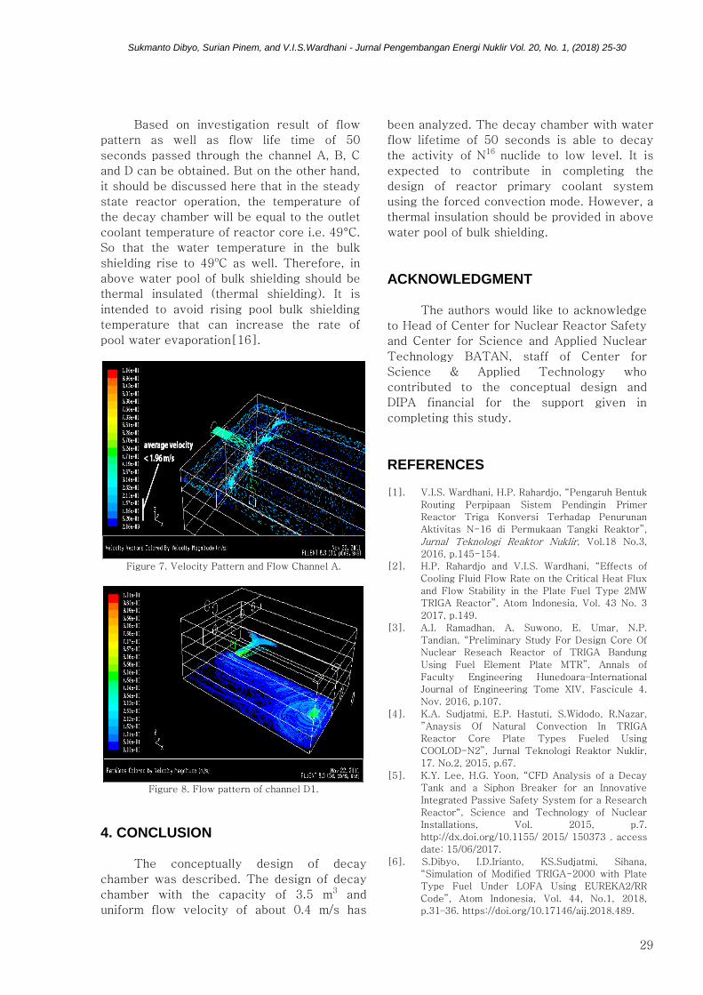
Figure 7. Velocity Pattern and Flow Channel A.
Figure 8. Flow pattern of channel D1.
4. CONCLUSION
The conceptually design of decay
chamber was described. The design of decay
chamber with the capacity of 3.5 m3 and
uniform flow velocity of about 0.4 m/s has
been analyzed. The decay chamber with water
flow lifetime of 50 seconds is able to decay
the activity of N16 nuclide to low level. It is
expected to contribute in completing the
design of reactor primary coolant system
using the forced convection mode. However, a
thermal insulation should be provided in above
water pool of bulk shielding.
ACKNOWLEDGMENT
The authors would like to acknowledge
to Head of Center for Nuclear Reactor Safety
and Center for Science and Applied Nuclear
Technology BATAN, staff of Center for
Science & Applied Technology who
contributed to the conceptual design and
DIPA financial for the support given in
completing this study.
REFERENCES [1]. V.I.S. Wardhani, H.P. Rahardjo, “Pengaruh Bentuk
Routing Perpipaan Sistem Pendingin Primer
Reactor Triga Konversi Terhadap Penurunan
Aktivitas N-16 di Permukaan Tangki Reaktor”,
Jurnal Teknologi Reaktor Nuklir, Vol.18 No.3,
2016, p.145-154.
[2]. H.P. Rahardjo and V.I.S. Wardhani, “Effects of
Cooling Fluid Flow Rate on the Critical Heat Flux
and Flow Stability in the Plate Fuel Type 2MW
TRIGA Reactor”, Atom Indonesia, Vol. 43 No. 3
2017, p.149.
[3]. A.I. Ramadhan, A. Suwono, E. Umar, N.P.
Tandian, “Preliminary Study For Design Core Of
Nuclear Reseach Reactor of TRIGA Bandung
Using Fuel Element Plate MTR”, Annals of
Faculty Engineering Hunedoara–International
Journal of Engineering Tome XIV, Fascicule 4.
Nov. 2016, p.107.
[4]. K.A. Sudjatmi, E.P. Hastuti, S.Widodo, R.Nazar,
”Anaysis Of Natural Convection In TRIGA
Reactor Core Plate Types Fueled Using
COOLOD-N2”, Jurnal Teknologi Reaktor Nuklir,
17. No.2, 2015, p.67.
[5]. K.Y. Lee, H.G. Yoon, “CFD Analysis of a Decay
Tank and a Siphon Breaker for an Innovative
Integrated Passive Safety System for a Research
Reactor“, Science and Technology of Nuclear
Installations, Vol. 2015, p.7.
http://dx.doi.org/10.1155/ 2015/ 150373 . access
date: 15/06/2017.
[6]. S.Dibyo, I.D.Irianto, KS.Sudjatmi, Sihana,
“Simulation of Modified TRIGA-2000 with Plate
Type Fuel Under LOFA Using EUREKA2/RR
Code”, Atom Indonesia, Vol. 44, No.1, 2018,
p.31–36. https://doi.org/10.17146/aij.2018.489.

Sukmanto Dibyo, Surian Pinem, and V.I.S.Wardhani - Jurnal Pengembangan Energi Nuklir Vol. 20, No. 1, (2018) 25-30
30
[7]. N. Sadeghi, “Estimation of reactor power using
N-16 production rate and its radiation risk
assessment in TRR”. Nuclear Engineering and
Design, 2010, 240, p.3607.
[8]. T.Y. Noh B.G. Park, M.S. Kim, “Estimation of
nuclear heating by delayed gamma rays from
radioactive structural materials of HANARO”,
Nuclear Engineering and Technology, Vol. 50,
Issue 3, 2018, p.446-452.
[9]. M.A. Hoq, M.A. Malek Soner, M.A. Salam, S.
Khanoma, S.M. Fahad, “Assessment of N-16
Activity Concentration in Bangladesh Atomic
Energy Commission TRIGA Research Reactor”,
Nuclear Engineering and Technology, xxx, 2017,
1 doi.org/10.1016/j.net.2017.11.006, access date:
08/02/2018.
[10]. N. Jeong, G. Roh, S. Kim, J. Yoon, “Design
evaluation of decay tank for a pool-type
research reactor from the required minimum flow
residence time point of view”, Journal of Nuclear
Science and Technology, 2014, Vol. 51, No.9,
p.1064.dx.doi.org/10.1080/00223131.2014.91852
[11]. E. Umar, K. Kamajaya, A. Suwono, N.P. Tandian,
T. Hardianto, "An experimental Study of Natural
Convection in The Hottest Channel of TRIGA-
2000 kW Reactor”, Indonesian Journal of Nuclear
Science and Technology, Vol.6 No.1 Febr. 2005,
p.1.
[12]. Susyadi, H.Tjahjono, S.Dibyo, J.S.Pane,
"Investigasi Karakteristik Termohidrolika Teras
Reaktor Daya Kecil Dengan Pendinginan Sirkulasi
Alam Menggunakan RELAP5”, Jurnal Teknologi
Reaktor Nuklir, Vol.18, No.1, 2016, p. 1-10, (in
Indonesian).http://dx.doi.org/10.17146/tdm.2016.
18.1.2330 , access date: 15/01/2018.
[13]. K. Kamajaya, P.R. Henky, E. Umar, P.I. Yazid,
”Core Sub-Cooled Boiling Of The Bandung
TRIGA-2000 Reactor”, Jurnal Mesin itb, Vol. 23,
No 2, 2008, p.62.
[14]. R.B. Bird, W.E. Stewart and E.N. Lightfoot,
“Interphase Transport in Isothermal System”,
Transport Phenomena, Chapter 6, John Wiley &
Sons Inc, New York, 1960. p.186.
[15]. L. Byeonghee, S. Yang, S. Park,“Two Phase
Vertical Stratification in Decay Tank of Research
Reactor”, International Conference on Research
Reactors: Safe Management and Effective
Utilization, 2015.
[16]. S. Dibyo, 2002, “Evaporation rate calculation of
the RSG-GAS Reactor Cooling pool water”,
Prosiding Seminar ke-7 TKPFN Bandung, 2002.
www.iaea.org/inis/collection/NCLCollectionStore/_Public
/37/092/37092492.pdf, access date: 05/02/2018.