Concept of the exhaust system of combustion engines used ... · PDF fileAn additional aspect...
4
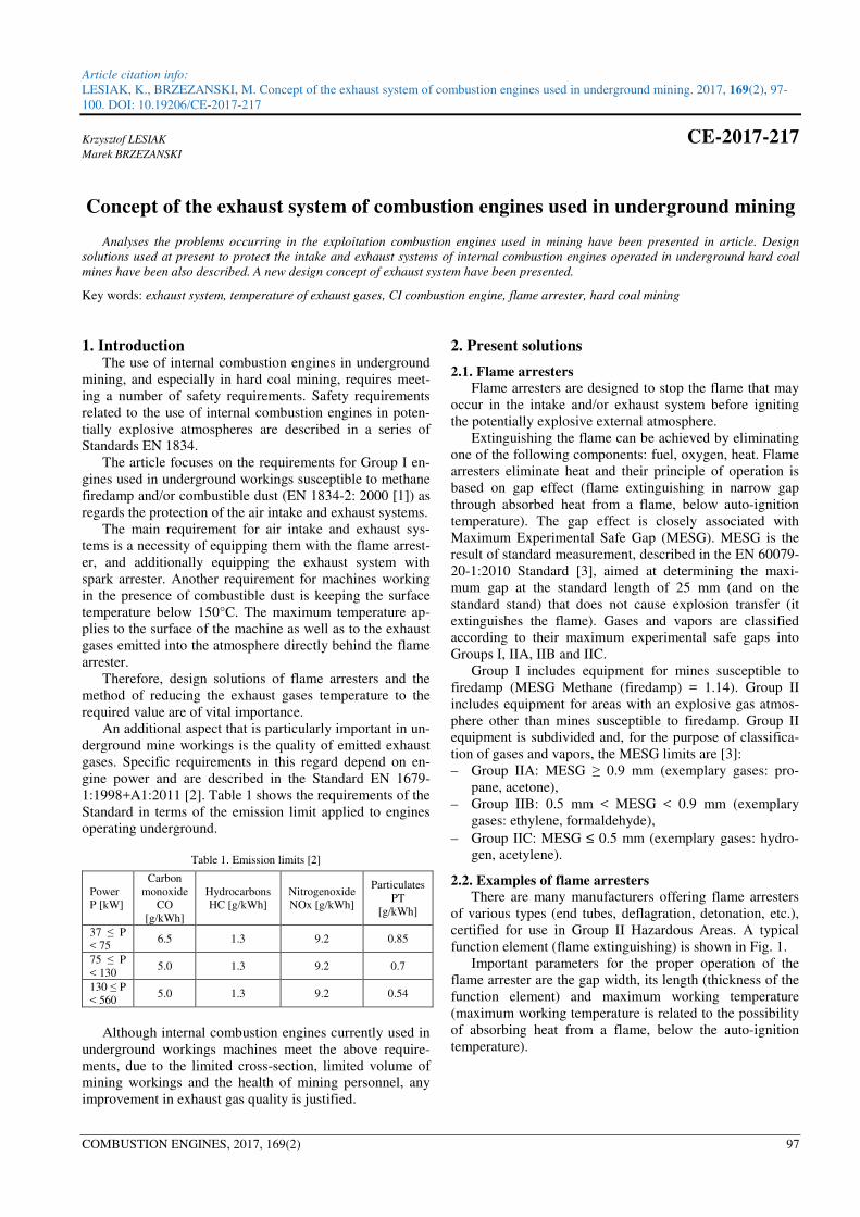
Article citation info: LESIAK, K., BRZEZANSKI, M. Concept of the exhaust system of combustion engines used in underground mining. 2017, 169(2), 97- 100. DOI: 10.19206/CE-2017-217 COMBUSTION ENGINES, 2017, 169(2) 97 Krzysztof LESIAK CE-2017-217 Marek BRZEZANSKI Concept of the exhaust system of combustion engines used in underground mining Analyses the problems occurring in the exploitation combustion engines used in mining have been presented in article. Design solutions used at present to protect the intake and exhaust systems of internal combustion engines operated in underground hard coal mines have been also described. A new design concept of exhaust system have been presented. Key words: exhaust system, temperature of exhaust gases, CI combustion engine, flame arrester, hard coal mining 1. Introduction The use of internal combustion engines in underground mining, and especially in hard coal mining, requires meet- ing a number of safety requirements. Safety requirements related to the use of internal combustion engines in poten- tially explosive atmospheres are described in a series of Standards EN 1834. The article focuses on the requirements for Group I en- gines used in underground workings susceptible to methane firedamp and/or combustible dust (EN 1834-2: 2000 [1]) as regards the protection of the air intake and exhaust systems. The main requirement for air intake and exhaust sys- tems is a necessity of equipping them with the flame arrest- er, and additionally equipping the exhaust system with spark arrester. Another requirement for machines working in the presence of combustible dust is keeping the surface temperature below 150°C. The maximum temperature ap- plies to the surface of the machine as well as to the exhaust gases emitted into the atmosphere directly behind the flame arrester. Therefore, design solutions of flame arresters and the method of reducing the exhaust gases temperature to the required value are of vital importance. An additional aspect that is particularly important in un- derground mine workings is the quality of emitted exhaust gases. Specific requirements in this regard depend on en- gine power and are described in the Standard EN 1679- 1:1998+A1:2011 [2]. Table 1 shows the requirements of the Standard in terms of the emission limit applied to engines operating underground. Table 1. Emission limits [2] Power P [kW] Carbon monoxide CO [g/kWh] Hydrocarbons HC [g/kWh] Nitrogenoxide NOx [g/kWh] Particulates PT [g/kWh] 37 ≤ P < 75 6.5 1.3 9.2 0.85 75 ≤ P < 130 5.0 1.3 9.2 0.7 130 ≤ P < 560 5.0 1.3 9.2 0.54 Although internal combustion engines currently used in underground workings machines meet the above require- ments, due to the limited cross-section, limited volume of mining workings and the health of mining personnel, any improvement in exhaust gas quality is justified. 2. Present solutions 2.1. Flame arresters Flame arresters are designed to stop the flame that may occur in the intake and/or exhaust system before igniting the potentially explosive external atmosphere. Extinguishing the flame can be achieved by eliminating one of the following components: fuel, oxygen, heat. Flame arresters eliminate heat and their principle of operation is based on gap effect (flame extinguishing in narrow gap through absorbed heat from a flame, below auto-ignition temperature). The gap effect is closely associated with Maximum Experimental Safe Gap (MESG). MESG is the result of standard measurement, described in the EN 60079- 20-1:2010 Standard [3], aimed at determining the maxi- mum gap at the standard length of 25 mm (and on the standard stand) that does not cause explosion transfer (it extinguishes the flame). Gases and vapors are classified according to their maximum experimental safe gaps into Groups I, IIA, IIB and IIC. Group I includes equipment for mines susceptible to firedamp (MESG Methane (firedamp) = 1.14). Group II includes equipment for areas with an explosive gas atmos- phere other than mines susceptible to firedamp. Group II equipment is subdivided and, for the purpose of classifica- tion of gases and vapors, the MESG limits are [3]: – Group IIA: MESG ≥ 0.9 mm (exemplary gases: pro- pane, acetone), – Group IIB: 0.5 mm < MESG < 0.9 mm (exemplary gases: ethylene, formaldehyde), – Group IIC: MESG ≤ 0.5 mm (exemplary gases: hydro- gen, acetylene). 2.2. Examples of flame arresters There are many manufacturers offering flame arresters of various types (end tubes, deflagration, detonation, etc.), certified for use in Group II Hazardous Areas. A typical function element (flame extinguishing) is shown in Fig. 1. Important parameters for the proper operation of the flame arrester are the gap width, its length (thickness of the function element) and maximum working temperature (maximum working temperature is related to the possibility of absorbing heat from a flame, below the auto-ignition temperature).
Transcript of Concept of the exhaust system of combustion engines used ... · PDF fileAn additional aspect...
Article citation info:
LESIAK, K., BRZEZANSKI, M. Concept of the exhaust system of combustion engines used in underground mining. 2017, 169(2), 97-
100. DOI: 10.19206/CE-2017-217
COMBUSTION ENGINES, 2017, 169(2) 97
Krzysztof LESIAK CE-2017-217 Marek BRZEZANSKI
Concept of the exhaust system of combustion engines used in underground mining
Analyses the problems occurring in the exploitation combustion engines used in mining have been presented in article. Design
solutions used at present to protect the intake and exhaust systems of internal combustion engines operated in underground hard coal
mines have been also described. A new design concept of exhaust system have been presented.
Key words: exhaust system, temperature of exhaust gases, CI combustion engine, flame arrester, hard coal mining
1. Introduction The use of internal combustion engines in underground
mining, and especially in hard coal mining, requires meet-
ing a number of safety requirements. Safety requirements
related to the use of internal combustion engines in poten-
tially explosive atmospheres are described in a series of
Standards EN 1834.
The article focuses on the requirements for Group I en-
gines used in underground workings susceptible to methane
firedamp and/or combustible dust (EN 1834-2: 2000 [1]) as
regards the protection of the air intake and exhaust systems.
The main requirement for air intake and exhaust sys-
tems is a necessity of equipping them with the flame arrest-
er, and additionally equipping the exhaust system with
spark arrester. Another requirement for machines working
in the presence of combustible dust is keeping the surface
temperature below 150°C. The maximum temperature ap-
plies to the surface of the machine as well as to the exhaust
gases emitted into the atmosphere directly behind the flame
arrester.
Therefore, design solutions of flame arresters and the
method of reducing the exhaust gases temperature to the
required value are of vital importance.
An additional aspect that is particularly important in un-
derground mine workings is the quality of emitted exhaust
gases. Specific requirements in this regard depend on en-
gine power and are described in the Standard EN 1679-
1:1998+A1:2011 [2]. Table 1 shows the requirements of the
Standard in terms of the emission limit applied to engines
operating underground.
Table 1. Emission limits [2]
Power
P [kW]
Carbon
monoxide
CO
[g/kWh]
Hydrocarbons
HC [g/kWh]
Nitrogenoxide
NOx [g/kWh]
Particulates
PT
[g/kWh]
37 ≤ P
< 75 6.5 1.3 9.2 0.85
75 ≤ P
< 130 5.0 1.3 9.2 0.7
130 ≤ P
< 560 5.0 1.3 9.2 0.54
Although internal combustion engines currently used in
underground workings machines meet the above require-
ments, due to the limited cross-section, limited volume of
mining workings and the health of mining personnel, any
improvement in exhaust gas quality is justified.
2. Present solutions
2.1. Flame arresters
Flame arresters are designed to stop the flame that may
occur in the intake and/or exhaust system before igniting
the potentially explosive external atmosphere.
Extinguishing the flame can be achieved by eliminating
one of the following components: fuel, oxygen, heat. Flame
arresters eliminate heat and their principle of operation is
based on gap effect (flame extinguishing in narrow gap
through absorbed heat from a flame, below auto-ignition
temperature). The gap effect is closely associated with
Maximum Experimental Safe Gap (MESG). MESG is the
result of standard measurement, described in the EN 60079-
20-1:2010 Standard [3], aimed at determining the maxi-
mum gap at the standard length of 25 mm (and on the
standard stand) that does not cause explosion transfer (it
extinguishes the flame). Gases and vapors are classified
according to their maximum experimental safe gaps into
Groups I, IIA, IIB and IIC.
Group I includes equipment for mines susceptible to
firedamp (MESG Methane (firedamp) = 1.14). Group II
includes equipment for areas with an explosive gas atmos-
phere other than mines susceptible to firedamp. Group II
equipment is subdivided and, for the purpose of classifica-
tion of gases and vapors, the MESG limits are [3]:
– Group IIA: MESG ≥ 0.9 mm (exemplary gases: pro-
pane, acetone),
– Group IIB: 0.5 mm < MESG < 0.9 mm (exemplary
gases: ethylene, formaldehyde),
– Group IIC: MESG ≤ 0.5 mm (exemplary gases: hydro-
gen, acetylene).
2.2. Examples of flame arresters
There are many manufacturers offering flame arresters
of various types (end tubes, deflagration, detonation, etc.),
certified for use in Group II Hazardous Areas. A typical
function element (flame extinguishing) is shown in Fig. 1.
Important parameters for the proper operation of the
flame arrester are the gap width, its length (thickness of the
function element) and maximum working temperature
(maximum working temperature is related to the possibility
of absorbing heat from a flame, below the auto-ignition
temperature).
Concept of the exhaust system of combustion engines used in underground mining
98 COMBUSTION ENGINES, 2017, 169(2)
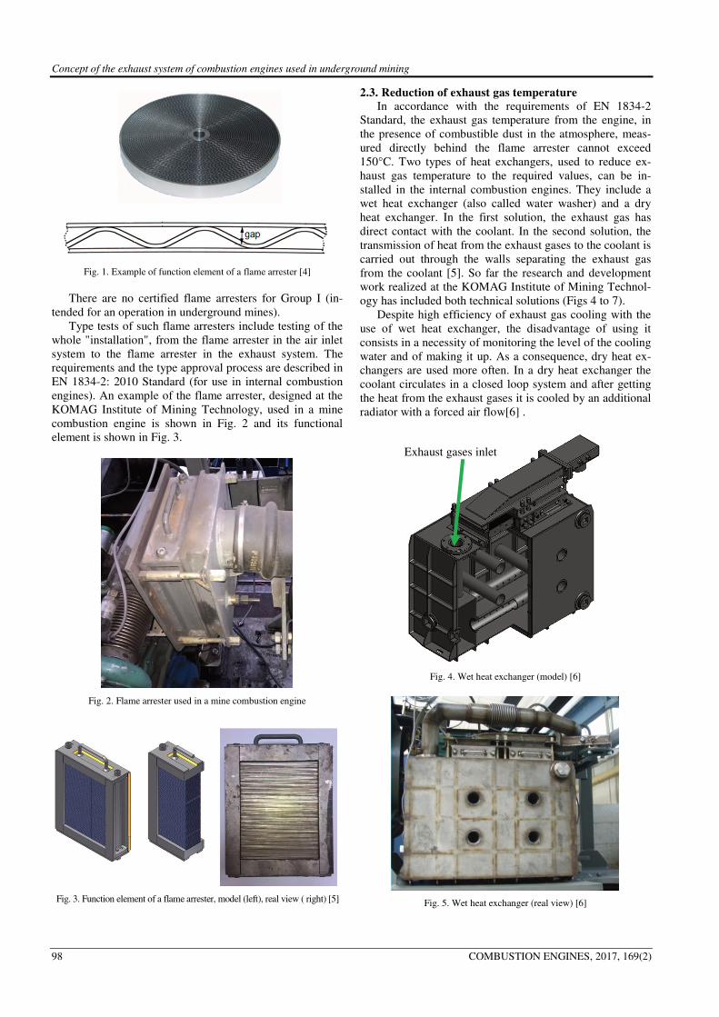
Fig. 1. Example of function element of a flame arrester [4]
There are no certified flame arresters for Group I (in-
tended for an operation in underground mines).
Type tests of such flame arresters include testing of the
whole "installation", from the flame arrester in the air inlet
system to the flame arrester in the exhaust system. The
requirements and the type approval process are described in
EN 1834-2: 2010 Standard (for use in internal combustion
engines). An example of the flame arrester, designed at the
KOMAG Institute of Mining Technology, used in a mine
combustion engine is shown in Fig. 2 and its functional
element is shown in Fig. 3.
Fig. 2. Flame arrester used in a mine combustion engine
Fig. 3. Function element of a flame arrester, model (left), real view ( right) [5]
2.3. Reduction of exhaust gas temperature
In accordance with the requirements of EN 1834-2
Standard, the exhaust gas temperature from the engine, in
the presence of combustible dust in the atmosphere, meas-
ured directly behind the flame arrester cannot exceed
150°C. Two types of heat exchangers, used to reduce ex-
haust gas temperature to the required values, can be in-
stalled in the internal combustion engines. They include a
wet heat exchanger (also called water washer) and a dry
heat exchanger. In the first solution, the exhaust gas has
direct contact with the coolant. In the second solution, the
transmission of heat from the exhaust gases to the coolant is
carried out through the walls separating the exhaust gas
from the coolant [5]. So far the research and development
work realized at the KOMAG Institute of Mining Technol-
ogy has included both technical solutions (Figs 4 to 7).
Despite high efficiency of exhaust gas cooling with the
use of wet heat exchanger, the disadvantage of using it
consists in a necessity of monitoring the level of the cooling
water and of making it up. As a consequence, dry heat ex-
changers are used more often. In a dry heat exchanger the
coolant circulates in a closed loop system and after getting
the heat from the exhaust gases it is cooled by an additional
radiator with a forced air flow[6] .
Fig. 4. Wet heat exchanger (model) [6]
Fig. 5. Wet heat exchanger (real view) [6]
Exhaust gases inlet
Concept of the exhaust system of combustion engines used in underground mining
COMBUSTION ENGINES, 2017, 169(2) 99
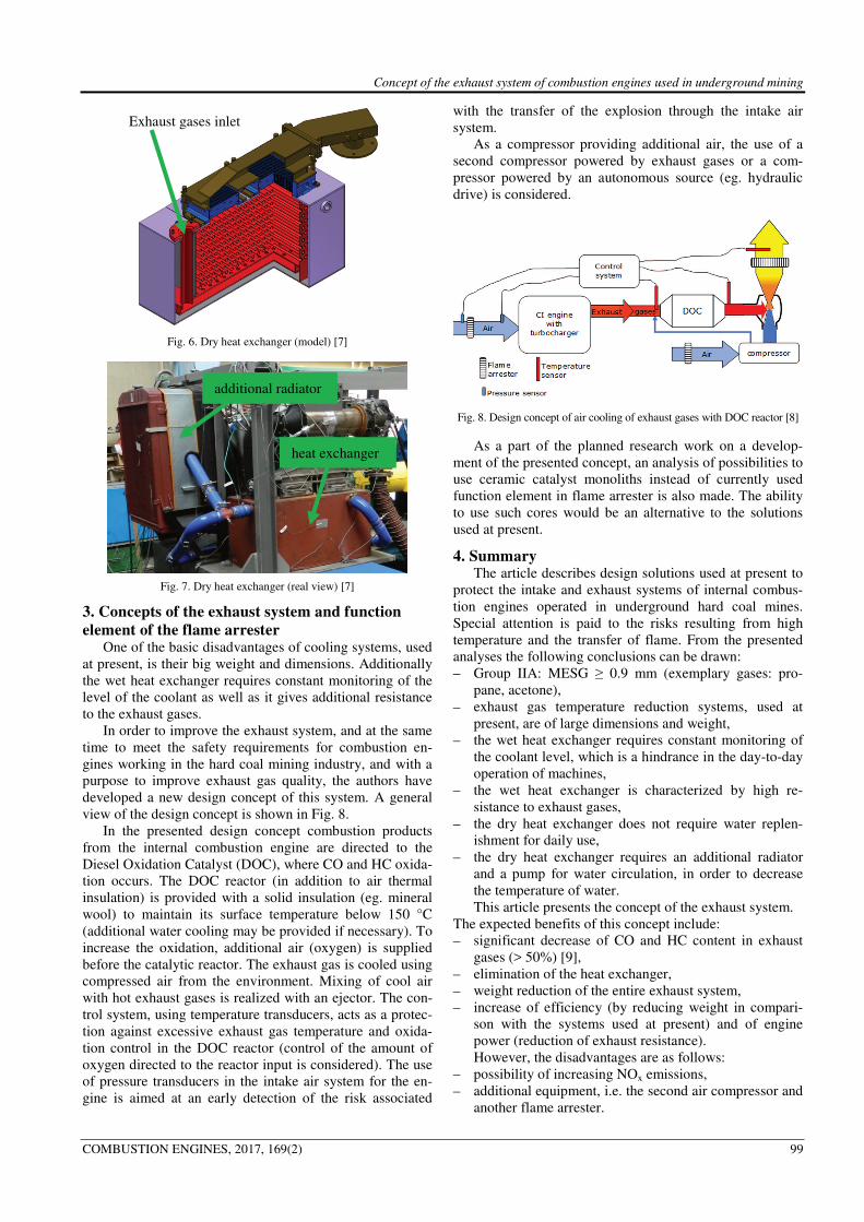
Fig. 6. Dry heat exchanger (model) [7]
Fig. 7. Dry heat exchanger (real view) [7]
3. Concepts of the exhaust system and function
element of the flame arrester One of the basic disadvantages of cooling systems, used
at present, is their big weight and dimensions. Additionally
the wet heat exchanger requires constant monitoring of the
level of the coolant as well as it gives additional resistance
to the exhaust gases.
In order to improve the exhaust system, and at the same
time to meet the safety requirements for combustion en-
gines working in the hard coal mining industry, and with a
purpose to improve exhaust gas quality, the authors have
developed a new design concept of this system. A general
view of the design concept is shown in Fig. 8.
In the presented design concept combustion products
from the internal combustion engine are directed to the
Diesel Oxidation Catalyst (DOC), where CO and HC oxida-
tion occurs. The DOC reactor (in addition to air thermal
insulation) is provided with a solid insulation (eg. mineral
wool) to maintain its surface temperature below 150 °C
(additional water cooling may be provided if necessary). To
increase the oxidation, additional air (oxygen) is supplied
before the catalytic reactor. The exhaust gas is cooled using
compressed air from the environment. Mixing of cool air
with hot exhaust gases is realized with an ejector. The con-
trol system, using temperature transducers, acts as a protec-
tion against excessive exhaust gas temperature and oxida-
tion control in the DOC reactor (control of the amount of
oxygen directed to the reactor input is considered). The use
of pressure transducers in the intake air system for the en-
gine is aimed at an early detection of the risk associated
with the transfer of the explosion through the intake air
system.
As a compressor providing additional air, the use of a
second compressor powered by exhaust gases or a com-
pressor powered by an autonomous source (eg. hydraulic
drive) is considered.
Fig. 8. Design concept of air cooling of exhaust gases with DOC reactor [8]
As a part of the planned research work on a develop-
ment of the presented concept, an analysis of possibilities to
use ceramic catalyst monoliths instead of currently used
function element in flame arrester is also made. The ability
to use such cores would be an alternative to the solutions
used at present.
4. Summary The article describes design solutions used at present to
protect the intake and exhaust systems of internal combus-
tion engines operated in underground hard coal mines.
Special attention is paid to the risks resulting from high
temperature and the transfer of flame. From the presented
analyses the following conclusions can be drawn:
– Group IIA: MESG ≥ 0.9 mm (exemplary gases: pro-
pane, acetone),
– exhaust gas temperature reduction systems, used at
present, are of large dimensions and weight,
– the wet heat exchanger requires constant monitoring of
the coolant level, which is a hindrance in the day-to-day
operation of machines,
– the wet heat exchanger is characterized by high re-
sistance to exhaust gases,
– the dry heat exchanger does not require water replen-
ishment for daily use,
– the dry heat exchanger requires an additional radiator
and a pump for water circulation, in order to decrease
the temperature of water.
This article presents the concept of the exhaust system.
The expected benefits of this concept include:
– significant decrease of CO and HC content in exhaust
gases (> 50%) [9],
– elimination of the heat exchanger,
– weight reduction of the entire exhaust system,
– increase of efficiency (by reducing weight in compari-
son with the systems used at present) and of engine
power (reduction of exhaust resistance).
However, the disadvantages are as follows:
– possibility of increasing NOx emissions,
– additional equipment, i.e. the second air compressor and
another flame arrester.
heat exchanger
Exhaust gases inlet
additional radiator
Concept of the exhaust system of combustion engines used in underground mining
100 COMBUSTION ENGINES, 2017, 169(2)
As a part of the development work on the concept, nu-
merical analyses are planned to determine the technical
parameters of the compressor used for cooling the exhaust
gases and the ejector element. As a part of the research
work on the possible use of ceramic monoliths, the first step
includes testing the abrasion resistance of ceramic material
which, according to the requirements of EN 1834-2: 2002
Standard, must be equal to or better than for stainless steel
14404 or 14435.
Bibliography
[1] EN 1834-2:2000 Reciprocating internal combustion engines.
Safety requirements for design and construction of engines
for use in potentially explosive atmospheres. Group I en-
gines for use in underground workings susceptible to fire-
damp and/or combustible dust.
[2] EN 1679-1:1998+A1:2011 Reciprocating internal combus-
tion engines. Safety. Compression ignition engines.
[3] EN 60079-20-1:2010 Explosive atmospheres. Material
characteristics for gas and vapour classification. Test met-
hods and data.
[4] www.techmako.pl, Przerywacze płomieni/Zawory odde-
chowe
[5] KACZMARCZYK K., BRZEŻAŃSKI, M. Problemy eko-
logiczne silników spalinowych eksploatowanych w wyrobi-
skach podziemnych węgla kamiennego Prace naukowe –
Monografie. Gliwice. 2015.
[6] DOBRZANIECKI, P. Modelowanie charakterystyk trakcyj-
nych napędów na przykładzie pojazdów górnictwa węglo-
wego. Praca doktorska. Gliwice 2012.
[7] KACZMARCZYK, K. Metoda dostosowania silnika do
wymagań stawianych górniczym napędom spalinowym.
Praca doktorska. Gliwice 2014.
[8] LESIAK, K. Redukcja toksycznych składników w spalinach
silników wysokoprężnych oraz optymalizacja układu wylo-
towego spalin. ITG KOMAG, Gliwice 2016, materiały nie-
publikowane.
[9] KRUCZYŃSKI, S., DANILCZYK, W. Ograniczanie szko-
dliwości gazów wylotowych silników spalinowych poprzez
zastosowanie reaktorów katalitycznych. MOTROL. 2007, 9,
93-102.
Marek Brzeżański, DSc., DEng. – Faculty of Me-
chanical Engineering at Cracow University of Tech-
nology.
e-mail: [email protected]
Krzysztof Lesiak, MEng. – KOMAG Institute of
Mining Technology.
e-mail: [email protected]