Concentric Butterfly Valve - HABLEM · Concentric Butterfly Valves The Concentric Design CCENTER OF...
9
139-12, 1430 beon-gil, Seobu-ro, Juchon-myun, Gimhae-si, Gyeongsangnam-do, Korea. ▶TEL +82-55-310-8000 ▶FAX +82-55-329-0656~8 ▶E-mail [email protected] ▶Homepage www.acevalve.co.kr Concentric Butterfly Valve Concentric Butterfly Valve
Transcript of Concentric Butterfly Valve - HABLEM · Concentric Butterfly Valves The Concentric Design CCENTER OF...
139-12, 1430 beon-gil, Seobu-ro, Juchon-myun, Gimhae-si, Gyeongsangnam-do, Korea.
▶TEL +82-55-310-8000▶FAX +82-55-329-0656~8▶E-mail [email protected]▶Homepage www.acevalve.co.kr
Concentric Butterfly Valve
Concentric Butterfly Valve
ACE VALVE PRODUCT GUIDEBOOK | C-3ACE VALVE PRODUCT GUIDEBOOK | C-2
Technological Knowhow of
ACE VALVE
ACE VALVE has provided the best quality products by using accumulated technological knowhow and the most advanced machinery.
Now we challenge the whole world market of butterfly valve.
A Top - ranking company in the 21st century bychallenging the potential
Specification of Concentric Butterfly Valve
The valve shall be capable of bi-directional flow with bubble tightshut-off at full rating pressure.
TYPE NUMBERING SYSTEM• AV-CWR Concentric WAFER type Rubber lined Butterfly Valves• AV-CSR Concentric SEMI-LUG type Rubber lined Butterfly Valves• AV-CLR Concentric LUG type Rubber lined Butterfly Valves• AV-CFR Concentric FLANGE type Rubber lined Butterfly Valves
PRODUCTION RANGE• SIZE : DN 50mm (2 inch) ~ DN 4000mm (160 inch) • RATING PRESSURE : UP to 20 bar depend on related size • RATING TEMPERATURE : -20℃ ~ +200℃
APPLICABLE FLANGE• KS/JIS 5K, 10K, 16K • ASME B 16.1 Class 125LB • ASME B 16.5 Class 150LB • EN 1092 PN6, PN10, PN16• ISO 7005 PN6, PN10, PN16
STANDARD COMPLIANCE• ACE Concentric Butterfly valves conform to ISO 5752, KSV 7490, JIS F 7480, JIS B 2032, API 609, BS 5155, DIN2501.
Concentric Butterfly Valves
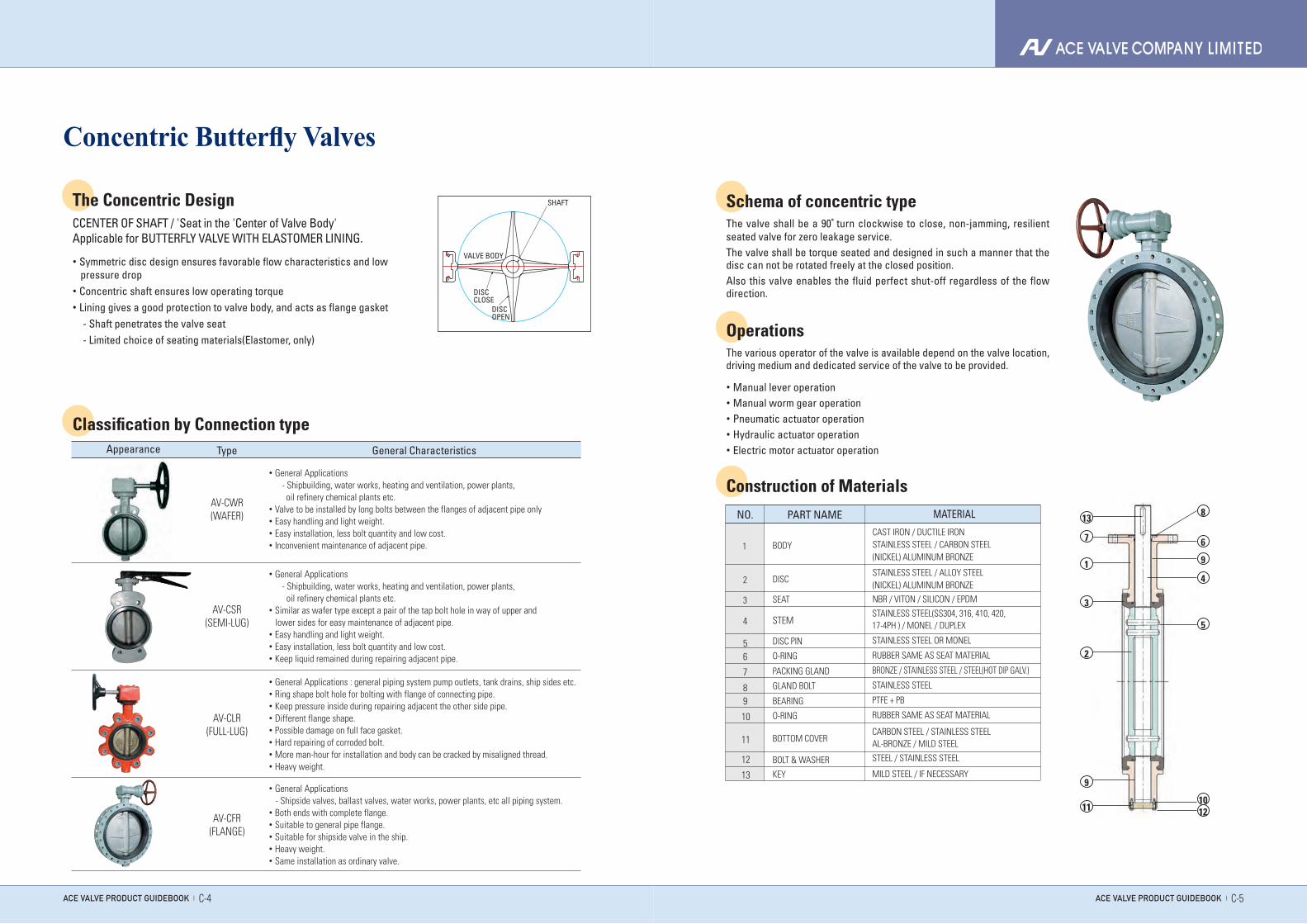
The Concentric DesignCCENTER OF SHAFT / 'Seat in the 'Center of Valve Body' Applicable for BUTTERFLY VALVE WITH ELASTOMER LINING.
Classification by Connection type
• Symmetric disc design ensures favorable flow characteristics and low pressure drop• Concentric shaft ensures low operating torque• Lining gives a good protection to valve body, and acts as flange gasket - Shaft penetrates the valve seat - Limited choice of seating materials(Elastomer, only)
VALVE BODY
SHAFT
DISCCLOSE
DISCOPEN
TypeAppearance General Characteristics
AV-CWR(WAFER)
• General Applications - Shipbuilding, water works, heating and ventilation, power plants, oil refinery chemical plants etc.• Valve to be installed by long bolts between the flanges of adjacent pipe only • Easy handling and light weight.• Easy installation, less bolt quantity and low cost.• Inconvenient maintenance of adjacent pipe.
AV-CSR(SEMI-LUG)
• General Applications - Shipbuilding, water works, heating and ventilation, power plants, oil refinery chemical plants etc.• Similar as wafer type except a pair of the tap bolt hole in way of upper and lower sides for easy maintenance of adjacent pipe.• Easy handling and light weight.• Easy installation, less bolt quantity and low cost.• Keep liquid remained during repairing adjacent pipe.
AV-CLR(FULL-LUG)
• General Applications : general piping system pump outlets, tank drains, ship sides etc.• Ring shape bolt hole for bolting with flange of connecting pipe.• Keep pressure inside during repairing adjacent the other side pipe.• Different flange shape.• Possible damage on full face gasket.• Hard repairing of corroded bolt.• More man-hour for installation and body can be cracked by misaligned thread.• Heavy weight.
AV-CFR(FLANGE)
• General Applications - Shipside valves, ballast valves, water works, power plants, etc all piping system.• Both ends with complete flange.• Suitable to general pipe flange.• Suitable for shipside valve in the ship.• Heavy weight.• Same installation as ordinary valve.
Schema of concentric typeThe valve shall be a 90° turn clockwise to close, non-jamming, resilient seated valve for zero leakage service.The valve shall be torque seated and designed in such a manner that the disc can not be rotated freely at the closed position.Also this valve enables the fluid perfect shut-off regardless of the flow direction.
OperationsThe various operator of the valve is available depend on the valve location, driving medium and dedicated service of the valve to be provided.
• Manual lever operation• Manual worm gear operation• Pneumatic actuator operation• Hydraulic actuator operation• Electric motor actuator operation
Construction of Materials
ACE VALVE PRODUCT GUIDEBOOK | C-5ACE VALVE PRODUCT GUIDEBOOK | C-4
MATERIAL
CAST IRON / DUCTILE IRONSTAINLESS STEEL / CARBON STEEL(NICKEL) ALUMINUM BRONZE
STAINLESS STEEL / ALLOY STEEL(NICKEL) ALUMINUM BRONZE
NBR / VITON / SILICON / EPDM
STAINLESS STEEL(SS304, 316, 410, 420,17-4PH ) / MONEL / DUPLEX
STAINLESS STEEL OR MONEL
RUBBER SAME AS SEAT MATERIAL
BRONZE / STAINLESS STEEL / STEEL(HOT DIP GALV.)
STAINLESS STEEL
PTFE + PB
RUBBER SAME AS SEAT MATERIAL
CARBON STEEL / STAINLESS STEEL AL-BRONZE / MILD STEEL
STEEL / STAINLESS STEEL
MILD STEEL / IF NECESSARY
PART NAMENO.
BODY1
DISC2
SEAT3
STEM4
56
7
89
10
11
12
13
DISC PIN
O-RING
PACKING GLAND
GLAND BOLT
BEARING
O-RING
BOTTOM COVER
BOLT & WASHER
KEY
813
7
1
3
2
9
11
6
9
4
5
1012
unit : mm
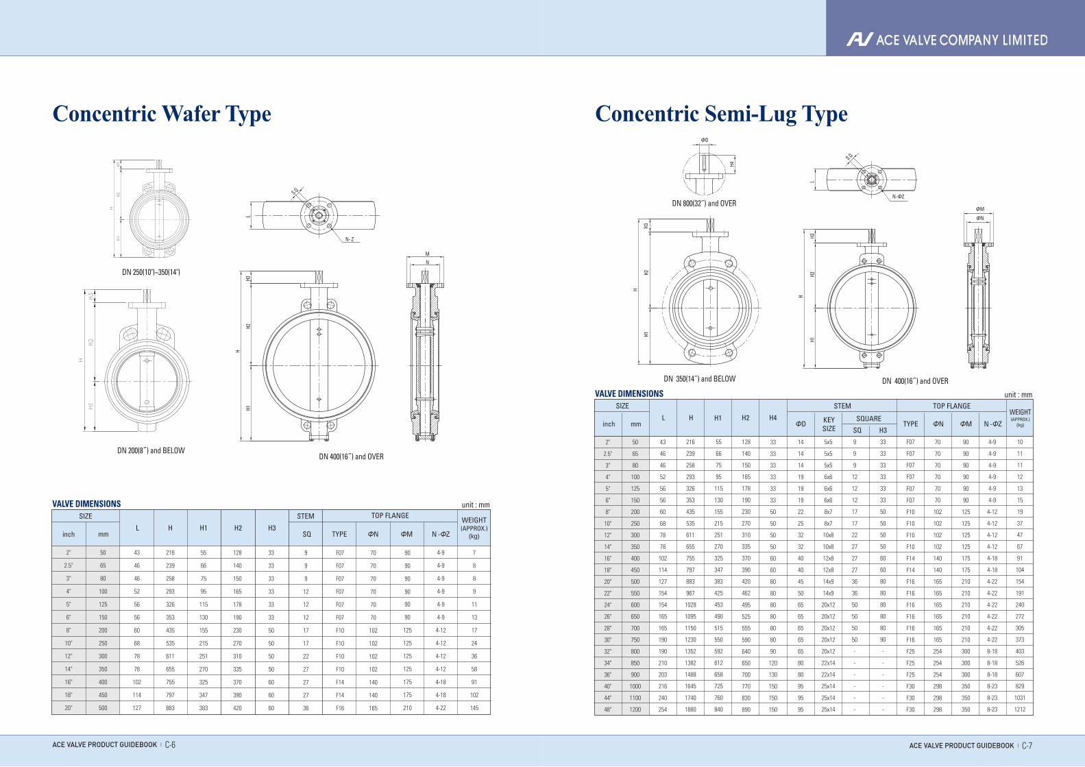
Concentric Wafer Type
ACE VALVE PRODUCT GUIDEBOOK | C-7ACE VALVE PRODUCT GUIDEBOOK | C-6
Concentric Semi-Lug Type
2"
2.5"
3"
4"
5"
6"
8"
10"
12"
14"
16"
18"
20"
50
65
80
100
125
150
200
250
300
350
400
450
500
43
46
46
52
56
56
60
68
78
78
102
114
127
216
239
258
293
326
353
435
535
611
655
755
797
883
55
66
75
95
115
130
155
215
251
270
325
347
383
128
140
150
165
178
190
230
270
310
335
370
390
420
33
33
33
33
33
33
50
50
50
50
60
60
60
9
9
9
12
12
12
17
17
22
27
27
27
36
F07
F07
F07
F07
F07
F07
F10
F10
F10
F10
F14
F14
F16
70
70
70
70
70
70
102
102
102
102
140
140
165
90
90
90
90
90
90
125
125
125
125
175
175
210
4-9
4-9
4-9
4-9
4-9
4-9
4-12
4-12
4-12
4-12
4-18
4-18
4-22
7
8
8
9
11
13
17
24
36
58
91
102
145
mminch
SIZE
L H H1 H2 H3SQ TYPE ΦN ΦM N -ΦZ
WEIGHT(APPROX.)
(kg)
STEM TOP FLANGEVALVE DIMENSIONS
DN 400(16˝) and OVERDN 200(8˝) and BELOW
DN 250(10")~350(14")
DN 400(16˝) and OVERDN 350(14˝) and BELOW
DN 800(32˝) and OVER
H4
H3
H3
H2H2
H1
H1
H
H
N-ΦZ
L
ΦN
ΦM
ΦD
S.Q
LH3
H2H1
H
H3H2
H1
H
S.Q
N- Z
N M
2"
2.5"
3"
4"
5"
6"
8"
10"
12"
14"
16"
18"
20"
22"
24"
26"
28"
30"
32"
34"
36"
40"
44"
48"
50
65
80
100
125
150
200
250
300
350
400
450
500
550
600
650
700
750
800
850
900
1000
1100
1200
43
46
46
52
56
56
60
68
78
78
102
114
127
154
154
165
165
190
190
210
203
216
240
254
216
239
258
293
326
353
435
535
611
655
755
797
883
967
1028
1095
1150
1230
1352
1382
1488
1645
1740
1880
55
66
75
95
115
130
155
215
251
270
325
347
383
425
453
490
515
550
592
612
658
725
760
840
128
140
150
165
178
190
230
270
310
335
370
390
420
462
495
525
555
590
640
650
700
770
830
890
33
33
33
33
33
33
50
50
50
50
60
60
80
80
80
80
80
80
90
120
130
150
150
150
14
14
14
19
19
19
22
25
32
32
40
40
45
50
65
65
65
65
65
80
80
95
95
95
5x5
5x5
5x5
6x6
6x6
6x6
8x7
8x7
10x8
10x8
12x8
12x8
14x9
14x9
20x12
20x12
20x12
20x12
20x12
22x14
22x14
25x14
25x14
25x14
9
9
9
12
12
12
17
17
22
27
27
27
36
36
50
50
50
50
-
-
-
-
-
-
33
33
33
33
33
33
50
50
50
50
60
60
80
80
80
80
80
90
-
-
-
-
-
-
F07
F07
F07
F07
F07
F07
F10
F10
F10
F10
F14
F14
F16
F16
F16
F16
F16
F16
F25
F25
F25
F30
F30
F30
70
70
70
70
70
70
102
102
102
102
140
140
165
165
165
165
165
165
254
254
254
298
298
298
90
90
90
90
90
90
125
125
125
125
175
175
210
210
210
210
210
210
300
300
300
350
350
350
4-9
4-9
4-9
4-9
4-9
4-9
4-12
4-12
4-12
4-12
4-18
4-18
4-22
4-22
4-22
4-22
4-22
4-22
8-18
8-18
8-18
8-23
8-23
8-23
10
11
11
12
13
15
19
37
47
67
91
104
154
191
240
272
305
373
403
526
607
829
1031
1212
unit : mm
KEYSIZE
ΦDH4H2H1HL
mminch
SIZE
TYPE
WEIGHT(APPROX.)
(kg)ΦN ΦM N -ΦZSQUARE
STEM TOP FLANGE
SQ H3
VALVE DIMENSIONS
ACE VALVE PRODUCT GUIDEBOOK | C-9ACE VALVE PRODUCT GUIDEBOOK | C-8
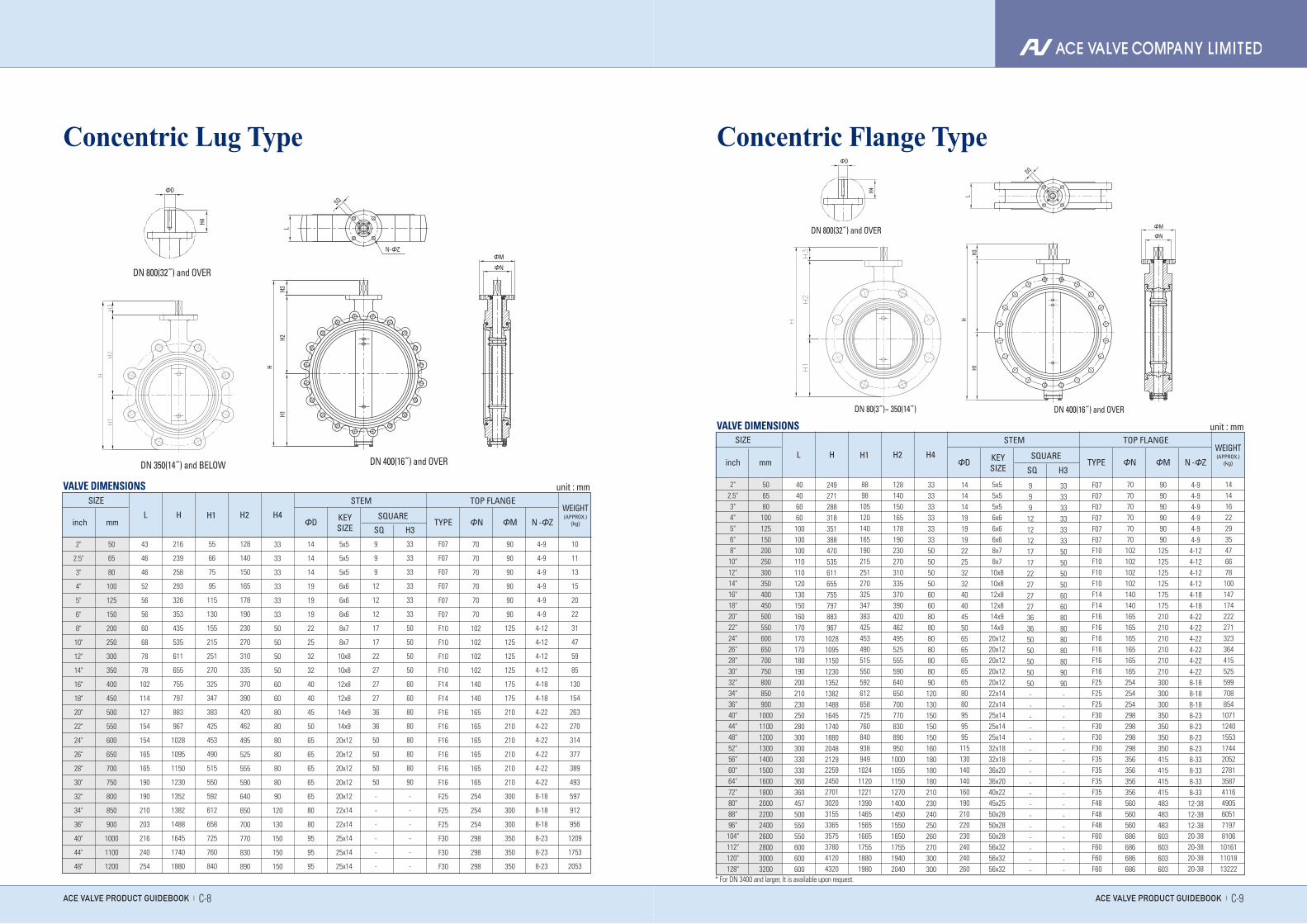
Concentric Lug Type Concentric Flange Type
DN 400(16˝) and OVERDN 350(14˝) and BELOW
DN 800(32˝) and OVERH2
H
H1H3
N-ΦZ
ΦN
ΦM
SQ
ΦD
H4
L
DN 400(16˝) and OVERDN 80(3˝)~ 350(14˝)
DN 800(32˝) and OVER
H
H1H3
ΦD
H4
SQ
L
ΦN
ΦM
2"
2.5"
3"
4"
5"
6"
8"
10"
12"
14"
16"
18"
20"
22"
24"
26"
28"
30"
32"
34"
36"
40"
44"
48"
50
65
80
100
125
150
200
250
300
350
400
450
500
550
600
650
700
750
800
850
900
1000
1100
1200
43
46
46
52
56
56
60
68
78
78
102
114
127
154
154
165
165
190
190
210
203
216
240
254
216
239
258
293
326
353
435
535
611
655
755
797
883
967
1028
1095
1150
1230
1352
1382
1488
1645
1740
1880
55
66
75
95
115
130
155
215
251
270
325
347
383
425
453
490
515
550
592
612
658
725
760
840
128
140
150
165
178
190
230
270
310
335
370
390
420
462
495
525
555
590
640
650
700
770
830
890
33
33
33
33
33
33
50
50
50
50
60
60
80
80
80
80
80
80
90
120
130
150
150
150
14
14
14
19
19
19
22
25
32
32
40
40
45
50
65
65
65
65
65
80
80
95
95
95
5x5
5x5
5x5
6x6
6x6
6x6
8x7
8x7
10x8
10x8
12x8
12x8
14x9
14x9
20x12
20x12
20x12
20x12
20x12
22x14
22x14
25x14
25x14
25x14
9
9
9
12
12
12
17
17
22
27
27
27
36
36
50
50
50
50
-
-
-
-
-
-
33
33
33
33
33
33
50
50
50
50
60
60
80
80
80
80
80
90
-
-
-
-
-
-
F07
F07
F07
F07
F07
F07
F10
F10
F10
F10
F14
F14
F16
F16
F16
F16
F16
F16
F25
F25
F25
F30
F30
F30
70
70
70
70
70
70
102
102
102
102
140
140
165
165
165
165
165
165
254
254
254
298
298
298
90
90
90
90
90
90
125
125
125
125
175
175
210
210
210
210
210
210
300
300
300
350
350
350
4-9
4-9
4-9
4-9
4-9
4-9
4-12
4-12
4-12
4-12
4-18
4-18
4-22
4-22
4-22
4-22
4-22
4-22
8-18
8-18
8-18
8-23
8-23
8-23
10
11
13
15
20
22
31
47
59
85
130
154
263
270
314
377
389
493
597
912
956
1209
1753
2053
unit : mm
KEYSIZE
ΦDH4H2H1HL
mminch
SIZE
TYPE
WEIGHT(APPROX.)
(kg)ΦN ΦM N -ΦZSQUARE
STEM TOP FLANGE
SQ H3
VALVE DIMENSIONS
* For DN 3400 and larger, It is available upon request.
WEIGHT(APPROX.)
(kg)KEYSIZE
ΦDH4H2H1HL
mminch
SIZE
TYPE ΦN ΦM N -ΦZSQUARE
STEM TOP FLANGE
SQ H3
2"2.5"3"4"5"6"8"10"12"14"16"18"20"22"24"26"28"30"32"34"36"40"44"48"52"56"60"64"72"80"88"96"104"112"120"128"
506580100125150200250300350400450500550600650700750800850900
100011001200130014001500160018002000220024002600280030003200
40406060100100100110110120130150160170170170180190200210230250280300300330330360360457500550550600600600
249271288318351388470535611655755797883967
1028109511501230135213821488164517401880204821292259245027013020315533653575378041204320
8898
105120140165190215251270325347383425453490515550592612658725760840938949
1024112012211390146515651665175518801980
12814015016517819023027031033537039042046249552555559064065070077083089095010001055115012701400145015501650175519402040
33333333333350505050606080808080808090
120130150150150160180180180210230240250260270300300
141414191919222532324040455065656565658080959595
115130140140160190210220230240240260
5x55x55x56x66x66x68x78x710x810x812x812x814x914x9
20x1220x1220x1220x1220x1222x1422x1425x1425x1425x1432x1832x1836x2036x2040x2245x2550x2850x2850x2856x3256x3256x32
999
12121217172227272736365050505050-----------------
33333333333350505050606080808080809090-----------------
F07F07F07F07F07F07F10F10F10F10F14F14F16F16F16F16F16F16F25F25F25F30F30F30F30F35F35F35F35F48F48F48F60F60F60F60
707070707070102102102102140140165165165165165165254254254298298298298356356356356560560560686686686686
909090909090125125125125175175210210210210210210300300300350350350350415415415415483483483603603603603
4-94-94-94-94-94-94-124-124-124-124-184-184-224-224-224-224-224-228-188-188-188-238-238-238-238-338-338-338-33
12-3812-3812-3820-3820-3820-3820-38
14 14 16 22 29 35 47 66 78 100 147 174 222 271 323 364 415 525 599 708 854 1071 1240 1553 1744 2052 2781 3587 4116 4905 60517197 8106
10161 11018 13222
unit : mmVALVE DIMENSIONS
WEIGHT(APPROX.)
(kg)
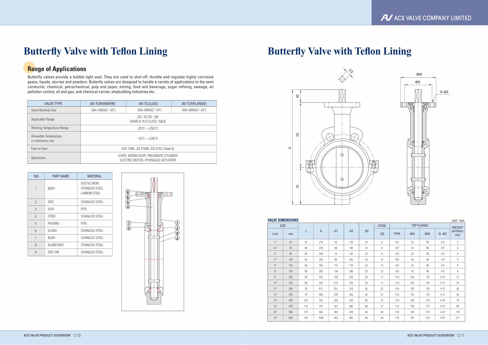
Range of ApplicationsButterfly valves provide a bubble tight seal. They are used to shut-off, throttle and regulate highly corrosive gases, liquids, slurries and powders. Butterfly valves are designed to handle a variety of applications to the semi conductor, chemical, petrochemical, pulp and paper, mining, food and beverage, sugar refining, sewage, air pollution control, oil and gas, and chemical carrier, shipbuilding industries etc.
Butterfly Valve with Teflon Lining Butterfly Valve with Teflon Lining
NO. PART NAME
1
2
3
4
5
6
7
8
9
MATERIAL
DUCTILE IRONSTAINLESS STEELCARBON STEEL
STAINLESS STEEL
PTFE
STAINLESS STEEL
PTFE
STAINLESS STEEL
STAINLESS STEEL
STAINLESS STEEL
STAINLESS STEEL
BODY
DISC
SEAT
STEM
PACKING
GLAND
BUSH
GLAND BOLT
DISC PIN
AV-TLW(WAFER) AV-TLL(LUG) AV-TLF(FLANGE)VALVE TYPE
Valve Nominal Size
Applicable Flange
Working Temperature Range
Face to Face
Allowable Temperature in continuous use
Operations
50A~500A(2"~20") 50A~600A(2"~24") 50A~600A(2"~24")
JIS / KS 5K, 10KASME B 16.5 CLASS 150LB
LEVER, WORM GEAR, PNEUMATIC CYLINDERELECTRIC MOTOR, HYDRAULIC ACTUATOR
-20℃ ~ +250℃
-10℃ ~ +230℃
KSV 7490, JIS F7480, ISO 5752 (Table 6)
ACE VALVE PRODUCT GUIDEBOOK | C-11ACE VALVE PRODUCT GUIDEBOOK | C-10
1
8654
75 3
92
H3H2
H1
H
S.QΦM
N-ΦZ
ΦN
VALVE DIMENSIONS unit : mm
2"
2.5"
3"
4"
5"
6"
8"
10"
12"
14"
16"
18"
20"
24"
50
65
80
100
125
150
200
250
300
350
400
450
500
600
43
46
46
52
56
56
60
68
78
78
102
114
127
154
216
239
258
293
326
353
435
535
611
655
755
797
883
1028
55
66
75
95
115
130
155
215
251
270
325
347
383
453
128
140
150
165
178
190
230
270
310
335
370
390
420
495
33
33
33
33
33
33
50
50
50
50
60
60
80
80
9
9
9
12
12
12
17
17
22
27
27
27
36
50
F07
F07
F07
F07
F07
F07
F10
F10
F10
F10
F14
F14
F16
F16
70
70
70
70
70
70
102
102
102
102
140
140
165
165
90
90
90
90
90
90
125
125
125
125
175
175
210
210
4-9
4-9
4-9
4-9
4-9
4-9
4-12
4-12
4-12
4-12
4-18
4-18
4-22
4-22
3
4
4
5
6
8
12
19
30
43
70
86
128
211
mminch
SIZE
L H H1 H2 H3SQ TYPE ΦN ΦM N -ΦZ
WEIGHT(APPROX.)
(kg)
STEM TOP FLANGE
ACE VALVE PRODUCT GUIDEBOOK | C-15ACE VALVE PRODUCT GUIDEBOOK | C-14
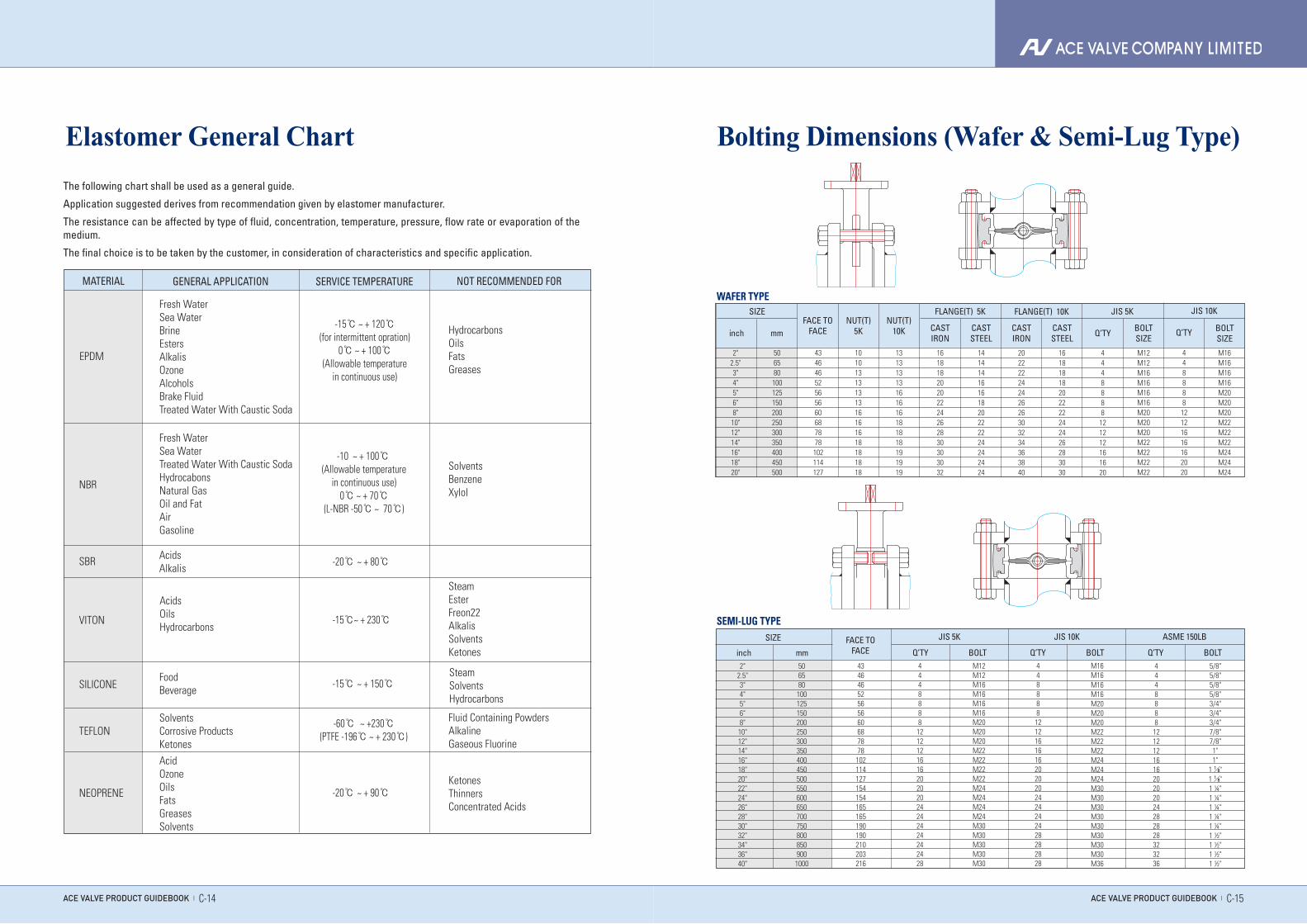
The following chart shall be used as a general guide.
Application suggested derives from recommendation given by elastomer manufacturer.
The resistance can be affected by type of fluid, concentration, temperature, pressure, flow rate or evaporation of the medium.
The final choice is to be taken by the customer, in consideration of characteristics and specific application.
MATERIAL
Fresh WaterSea WaterBrineEstersAlkalisOzoneAlcoholsBrake FluidTreated Water With Caustic Soda
Fresh WaterSea WaterTreated Water With Caustic SodaHydrocabonsNatural GasOil and FatAirGasoline
AcidsAlkalis
SolventsCorrosive ProductsKetonesAcidOzoneOilsFatsGreasesSolvents
FoodBeverage
GENERAL APPLICATION SERVICE TEMPERATURE NOT RECOMMENDED FOR
Elastomer General Chart
HydrocarbonsOilsFatsGreases
EPDM
NBR
SBR
SILICONE
TEFLON
NEOPRENE
-15℃ ~ + 120℃(for intermittent opration)
0℃ ~ + 100℃(Allowable temperature
in continuous use)
-10℃ ~ + 100℃℃(Allowable temperature
in continuous use)0℃ ~ + 70℃
(L-NBR -50℃ ~ 70℃)
-20℃ ~ + 80℃
-15℃ ~ + 150℃
-60℃ ~ +230℃(PTFE -196℃ ~ + 230℃)
-20℃ ~ + 90℃
SolventsBenzeneXylol
VITON -15℃~ + 230℃℃
SteamEsterFreon22AlkalisSolventsKetones
AcidsOilsHydrocarbons
SteamSolventsHydrocarbons
Fluid Containing PowdersAlkalineGaseous Fluorine
KetonesThinnersConcentrated Acids
2"2.5"3"4"5"6"8"10"12"14"16"18"20"22"24"26"28"30"32"34"36"40"
506580100125150200250300350400450500550600650700750800850900
1000
43464652565660687878102114127154154165165190190210203216
4448888
121212161620202024242424242428
M12M12M16M16M16M16M20M20M20M22M22M22M22M24M24M24M24M30M30M30M30M30
44888812121616162020202424242428282828
M16M16M16M16M20M20M20M22M22M22M24M24M24M30M30M30M30M30M30M30M30M36
4448888
121212161620202024282828323236
5/8"5/8"5/8"5/8"3/4"3/4"3/4"7/8"7/8"1"1"
1 ⅛"
1 ⅛"
1 ¼"1 ¼"1 ¼"1 ¼"1 ¼"1 ½"1 ½"1 ½"1 ½"
Bolting Dimensions (Wafer & Semi-Lug Type)
SEMI-LUG TYPESIZE
inch mmFACE TO
FACE Q’TY
JIS 5K
BOLT Q’TY
JIS 10K
BOLT Q’TY
ASME 150LB
BOLT
506580
100125150200250300350400450500
43464652565660687878
102114127
2"2.5"3"4"5"6"8"
10"12"14"16"18"20"
10101313131316161618181818
13131313161616181818191919
16181820202224262830303032
14141416161820222224242424
20222224242626303234363840
16181818202222242426283030
4448888121212161620
M12M12M16M16M16M16M20M20M20M22M22M22M22
448888
12121616162020
M16M16M16M16M20M20M20M22M22M22M24M24M24
FLANGE(T) 5K FLANGE(T) 10K JIS 5K JIS 10KNUT(T)
5KNUT(T)
10K CASTIRON
CASTSTEEL
SIZEFACE TO
FACE
WAFER TYPE
CASTIRON
CASTSTEEL Q’TY BOLT
SIZEQ’TY BOLT
SIZEinch mm
ACE VALVE PRODUCT GUIDEBOOK | C-17ACE VALVE PRODUCT GUIDEBOOK | C-16
G1 G3
T1 T3
L1 L3
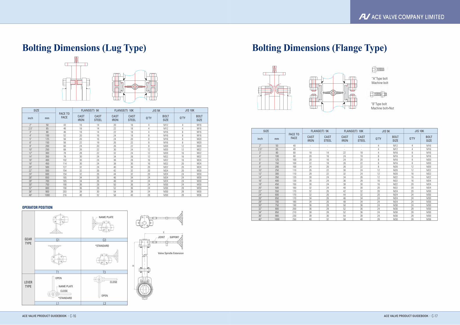
OPERATOR POSITION
Bolting Dimensions (Lug Type)
GEARTYPE
LEVERTYPE
NAME PLATE
OPEN
NAME PLATE
CLOSE
*STANDARD
*STANDARD
CLOSE
OPEN
NAME PLATE
OPEN
NAME PLATE
CLOSE
*STANDARD
*STANDARD
CLOSE
OPEN
NAME PLATE
OPEN
NAME PLATE
CLOSE
*STANDARD
*STANDARD
CLOSE
OPEN
NAME PLATE
OPEN
NAME PLATE
CLOSE
*STANDARD
*STANDARD
CLOSE
OPEN
Bolting Dimensions (Flange Type)
“A”Type boltMachine bolt
“B”Type boltMachine bolt+Nut
Valve Spindle Extension
JOINT
506580
100125150200250300350400450500550600650700750800900
1000
506580
100125150200250300350400450500550600650700750800850900
1000
43464652565660687878
102114127154154165165190190203216
40406060100100100110110120130150160170170170180190200210230250
2"2.5"3"4"5"6"8"
10"12"14"16"18"20"22"24"26"28"30"32"36"40"
2"2.5"3"4"5"6"8"
10"12"14"16"18"20"22"24"26"28"30"32"34"36"40"
161818202022242628303030323232343436363840
--
1820202224262830303032323234343636383840
141414161618202222242424242626262628283032
--
1416161820222224242424262626262828283032
202222242426263032343638404244464850525458
--
2224242626303234363840424446485052525458
161818182022222424262830303232343436363840
--
1818202222242426283030323234343636363840
44488881212121616202020242424242428
4448888121212161620202024242424242428
M12M12M16M16M16M16M20M20M20M22M22M22M22M24M24M24M24M30M30M30M30
M12M12M16M16M16M16M20M20M20M22M22M22M22M24M24M24M24M30M30M30M30M30
448888121216161620202024242424282828
44888812121616162020202424242428282828
M16M16M16M16M20M20M20M22M22M22M24M24M24M30M30M30M30M30M30M30M36
M16M16M16M16M20M20M20M22M22M22M24M24M24M30M30M30M30M30M30M30M30M36
FLANGE(T) 5K
FLANGE(T) 5K
FLANGE(T) 10K
FLANGE(T) 10K
JIS 5K
JIS 5K
JIS 10K
JIS 10K
CASTIRON
CASTIRON
CASTSTEEL
CASTSTEEL
SIZE
SIZE
FACE TOFACE
FACE TOFACE
CASTIRON
CASTIRON
CASTSTEEL
CASTSTEEL
Q’TY
Q’TY
BOLTSIZE
BOLTSIZE
Q’TY
Q’TY
BOLTSIZE
BOLTSIZE
inch
inch
mm
mm
ACE VALVE PRODUCT GUIDEBOOK | C-18
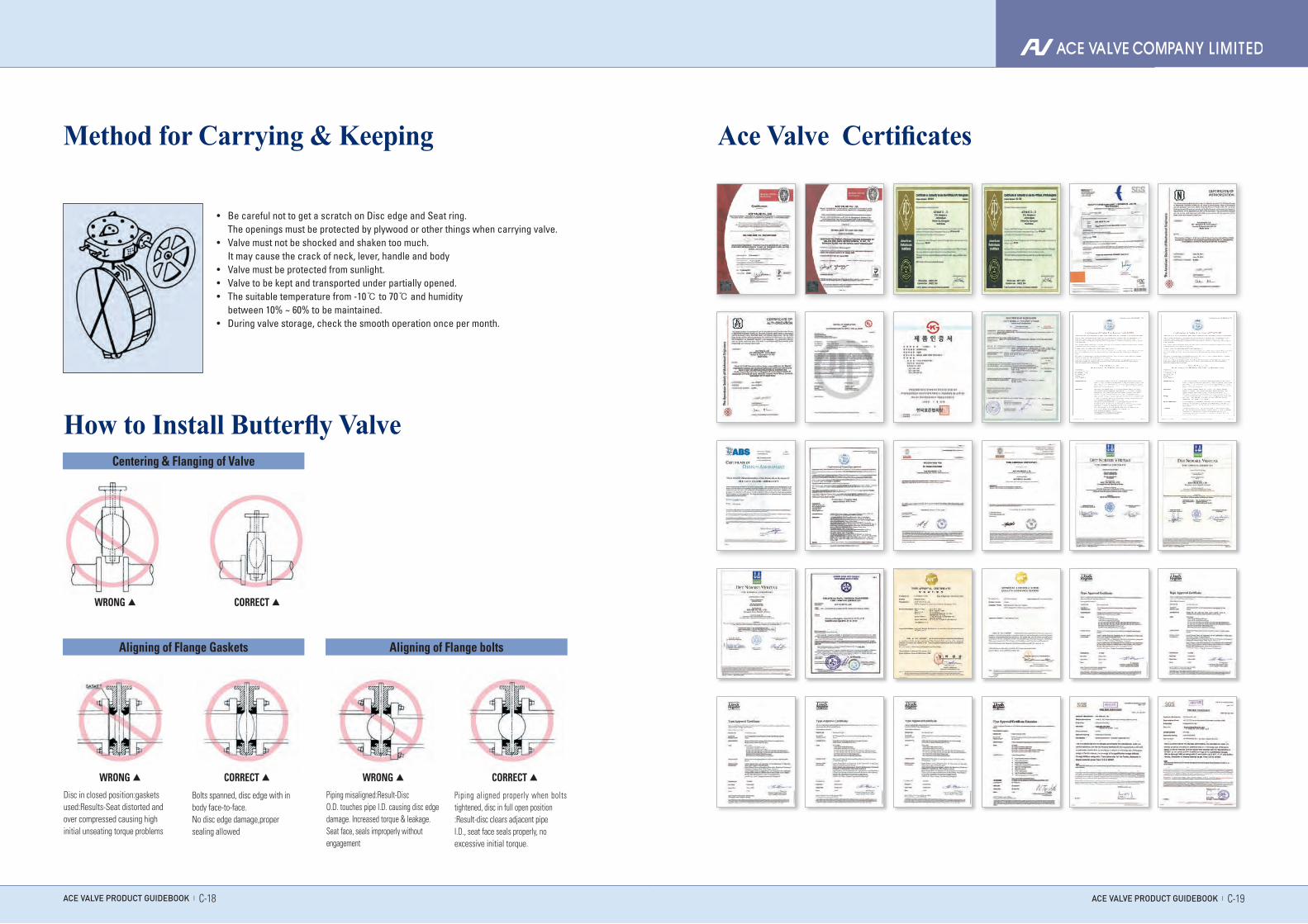
Method for Carrying & Keeping Ace Valve Certificates
How to Install Butterfly Valve
Aligning of Flange Gaskets
Centering & Flanging of Valve
Bolts spanned, disc edge with inbody face-to-face.No disc edge damage,propersealing allowed
• Be careful not to get a scratch on Disc edge and Seat ring. The openings must be protected by plywood or other things when carrying valve.• Valve must not be shocked and shaken too much. It may cause the crack of neck, lever, handle and body• Valve must be protected from sunlight.• Valve to be kept and transported under partially opened.• The suitable temperature from -10℃ to 70℃ and humidity between 10% ~ 60% to be maintained.• During valve storage, check the smooth operation once per month.
Aligning of Flange bolts
Piping misaligned:Result-DiscO.D. touches pipe I.D. causing disc edge damage. Increased torque & leakage.Seat face, seals improperly withoutengagement
Piping aligned properly when bolts tightened, disc in full open position:Result-disc clears adjacent pipeI.D., seat face seals properly, noexcessive initial torque.
WRONG ▲
WRONG ▲ WRONG ▲
CORRECT ▲
CORRECT ▲ CORRECT ▲
Disc in closed position:gasketsused:Results-Seat distorted andover compressed causing highinitial unseating torque problems
ACE VALVE PRODUCT GUIDEBOOK | C-19
ACE VALVE has provided the best quality products by using accumulated technological knowhow and the most advanced machinery.Now we challenge the whole world market of butterfly valve


![Section 18 Butterfly Valves - AAP Industries · BUTTERFLY VALVES [18] Wafer Butterfly Valve with Gear-Op Stainless Steel Wafer Butterfly Valve Wafer Butterfly Valve with Stainless](https://static.fdocuments.net/doc/165x107/60a1925cd0b68c353a5fc104/section-18-butterfly-valves-aap-industries-butterfly-valves-18-wafer-butterfly.jpg)