Concentration Method Development of Variable Rate Spring ...
5
540 APSAEM14 Jorunal of the Japan Society of Applied Electromagnetics and Mechanics Vol.23, No.3 (2015) (106) Development of Variable Rate Spring by Permanent Magnet with Flux Concentration Method Iwanori MURAKAMI *1 , Hiroto OHCHIAI *1 , Shunya MATUMOTO *1 and Yshinori ANDO *1 Springs are used for various purposes, particularly for vibration control and the removal of machines. However, the use of a spring generates a high amplitude at the resonance point; therefore, it is difficult to suppress vibrations from all frequency bands. To solve this issue, a variable rate spring is developed, which is a magnetic spring. This variable rate spring can change its spring constant. An experiment is carried out by placing compression and magnet- ic springs along the same axis to miniaturize the experimental device. Basically, the natural frequency of the vibration system fluctuates with changes in the spring constant. As a result, the problem can effectively be resolved by chang- ing the resonance point and suppressing the vibration. The variable rate spring consists of magnetic and compression springs; the utility of the spring is verified by an experiment and a simulation. Keywords: variable rate spring, flux concentration method, magnetic spring, vibration control. (Received: 24 July 2014, Revised: 25 May 2015) 1. Introduction The operation of vehicles and variable machines generates vibration. Thus, it is necessary to control and reduce vibration. In general, springs are used to control vibration in a machine. However, a large amplitude occurs when a spring reaches its natural frequency. Various methods have been researched to control vibration; one of these methods is the elimination of vibration by a magnetic spring. In general, an electro magnet can eliminate vibration. This is very effective for vibration control; however, electric power is always necessary, and the electromagnetic force is not large enough. Therefore, electronic magnets are only used for small devices mainly. A permanent magnet can gener- ate a strong magnetic force, and electric power is not necessary; however, it is difficult to control. Thus, if a permanent magnet is applied to a variable rate spring, the resulting spring could have a very large spring constant [1-6]. Therefore, we propose the development of a varia- ble rate spring that consists of compression and magnet- ic springs with a permanent magnet. First, the variable rate spring with a permanent magnet is proposed and combined with a compression spring. The magnetic spring with a permanent magnet is usually used for the repulsive magnetic force, but an attractive magnetic force is also possible in combination with the compres- sion spring. Thus, the variable region of the variable rate spring is realized. The problem associated with the magnetic spring is solved by simultaneously applying the compression spring, and the magnetic spring is only used to change the spring constant. This variable rate spring only needs electric power when changing the spring constant. In addition, the variable rate spring is semiactive, usually functioning as normal spring. Previously, the compression spring and two magnetic spring were set up in parallel, but the initial position of the moving part is different under attraction and repul- sion [8]. In this research, this variable rate spring is devel- oped, and the basic characteristics are clarified via simulation. Further, the usability of the spring is con- firmed with experiments and simulations. 2. Principle of the Variable Rate Spring In this research, a magnetic spring is used with a permanent magnet as an element to change the spring constant of the variable rate spring. It is impossible to change the spring constant actively from the initial state. Fig. 1 shows the rotating system of the magnetic spring. This magnetic spring consists of a pair of sets of mag- nets and one set of magnets has four poles. This system is rotated by a motor, and the permanent magnets face each other. Thus, it becomes possible to control the spring constant of the variable rate spring. It only needs _______________________ Correspondence: I. MURAKAMI, Faculty of Mechanical Science and Technology, Gunma University, 1-5-1 Tenjin- cho, Kiryu, Gunma 376-8515, Japan email: [email protected] *1 Gunma University Fig. 1. Model of the magnetic spring Regular Paper
Transcript of Concentration Method Development of Variable Rate Spring ...
540
APSAEM14 Jorunal of the Japan Society of Applied Electromagnetics and Mechanics Vol.23, No.3 (2015)
(106)
Development of Variable Rate Spring by Permanent Magnet with Flux Concentration Method
Iwanori MURAKAMI*1, Hiroto OHCHIAI*1, Shunya MATUMOTO*1 and Yshinori ANDO*1
Springs are used for various purposes, particularly for vibration control and the removal of machines. However, the use of a spring generates a high amplitude at the resonance point; therefore, it is difficult to suppress vibrations from all frequency bands. To solve this issue, a variable rate spring is developed, which is a magnetic spring. This variable rate spring can change its spring constant. An experiment is carried out by placing compression and magnet-ic springs along the same axis to miniaturize the experimental device. Basically, the natural frequency of the vibration system fluctuates with changes in the spring constant. As a result, the problem can effectively be resolved by chang-ing the resonance point and suppressing the vibration. The variable rate spring consists of magnetic and compression springs; the utility of the spring is verified by an experiment and a simulation.
Keywords: variable rate spring, flux concentration method, magnetic spring, vibration control. (Received: 24 July 2014, Revised: 25 May 2015)
1. Introduction
The operation of vehicles and variable machines generates vibration. Thus, it is necessary to control and reduce vibration. In general, springs are used to control vibration in a machine. However, a large amplitude occurs when a spring reaches its natural frequency. Various methods have been researched to control vibration; one of these methods is the elimination of vibration by a magnetic spring. In general, an electro magnet can eliminate vibration. This is very effective for vibration control; however, electric power is always necessary, and the electromagnetic force is not large enough. Therefore, electronic magnets are only used for small devices mainly. A permanent magnet can gener-ate a strong magnetic force, and electric power is not necessary; however, it is difficult to control. Thus, if a permanent magnet is applied to a variable rate spring, the resulting spring could have a very large spring constant [1-6].
Therefore, we propose the development of a varia-ble rate spring that consists of compression and magnet-ic springs with a permanent magnet. First, the variable rate spring with a permanent magnet is proposed and combined with a compression spring. The magnetic spring with a permanent magnet is usually used for the repulsive magnetic force, but an attractive magnetic force is also possible in combination with the compres-sion spring. Thus, the variable region of the variable rate spring is realized. The problem associated with the magnetic spring is solved by simultaneously applying the compression spring, and the magnetic spring is only
used to change the spring constant. This variable rate spring only needs electric power when changing the spring constant. In addition, the variable rate spring is semiactive, usually functioning as normal spring. Previously, the compression spring and two magnetic spring were set up in parallel, but the initial position of the moving part is different under attraction and repul-sion [8].
In this research, this variable rate spring is devel-oped, and the basic characteristics are clarified via simulation. Further, the usability of the spring is con-firmed with experiments and simulations.
2. Principle of the Variable Rate Spring
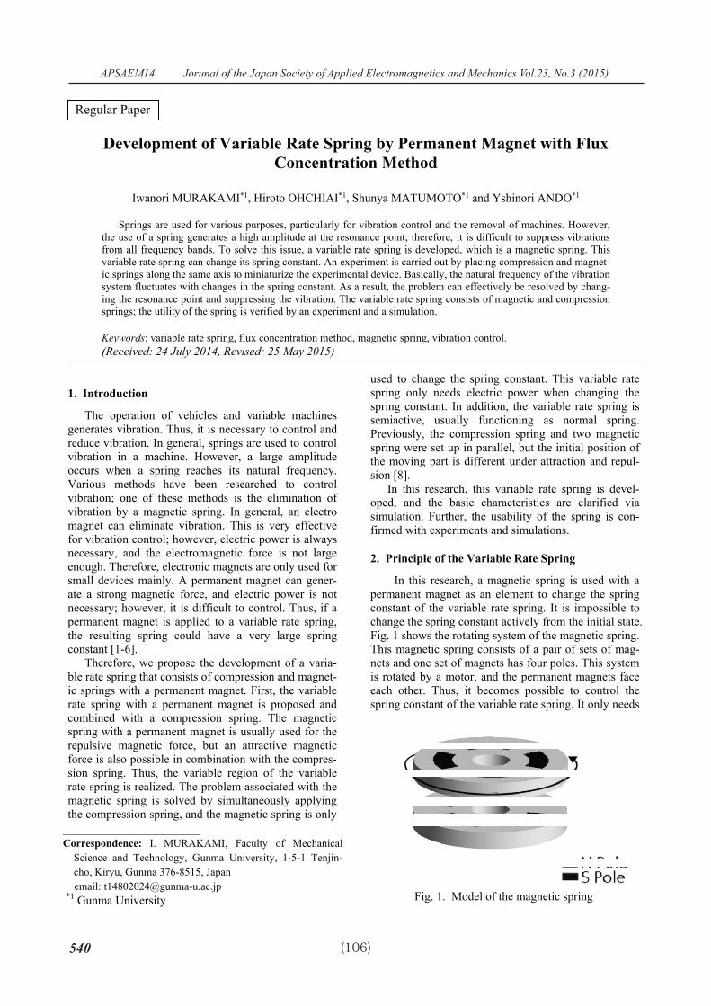
In this research, a magnetic spring is used with a permanent magnet as an element to change the spring constant of the variable rate spring. It is impossible to change the spring constant actively from the initial state. Fig. 1 shows the rotating system of the magnetic spring. This magnetic spring consists of a pair of sets of mag-nets and one set of magnets has four poles. This system is rotated by a motor, and the permanent magnets face each other. Thus, it becomes possible to control the spring constant of the variable rate spring. It only needs
_______________________ Correspondence: I. MURAKAMI, Faculty of Mechanical
Science and Technology, Gunma University, 1-5-1 Tenjin-cho, Kiryu, Gunma 376-8515, Japan email: [email protected]
*1 Gunma University Fig. 1. Model of the magnetic spring�
Regular Paper
日本 AEM 学会誌 Vol. 23, No.3 (2015)
541(107)
electric power to control the spring constant; thus, this mechanism is semi active. The magnet on the bottom is fixed, and the magnet on the top is rotated by changing the attractive and repulsive forces between the magnets. Thus, the spring constant of the magnetic spring is able to be changed. The magnetic field strength of the magnets facing each other becomes large by applying the flux concentration method.
In this research, the relative angle between the mag-nets for a completely attractive forces occurs at 0°, a completely repulsive force occurs at 90°, and equilibri-um occurs at 45°, in which no work is done on the spring.
3. Experimental Device
The experimental device consists of three parts: the excitation, joining, and variable rate spring parts. The mass of the exciting part is 54.15 kg, and each of the two eccentric masses has a mass of 0.1 kg. The eccen-tric radius is 60 mm.
Fig. 2 shows the model of the variable rate spring. The variable rate spring consists of a fixed magnet, rotating magnet, compression spring, and moving part. A linear guide vertically restricts the moving part. The rotating magnets are rotated by the motor and convert the attractive and repulsive forces. This experimental device has two pairs of magnets because the initial position of the moving part does not change by working force from up and down.
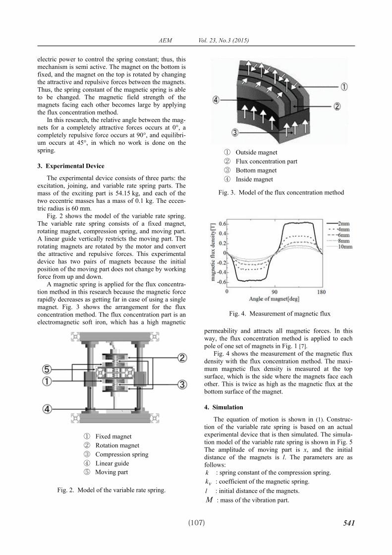
A magnetic spring is applied for the flux concentra-tion method in this research because the magnetic force rapidly decreases as getting far in case of using a single magnet. Fig. 3 shows the arrangement for the flux concentration method. The flux concentration part is an electromagnetic soft iron, which has a high magnetic
permeability and attracts all magnetic forces. In this way, the flux concentration method is applied to each pole of one set of magnets in Fig. 1 [7].
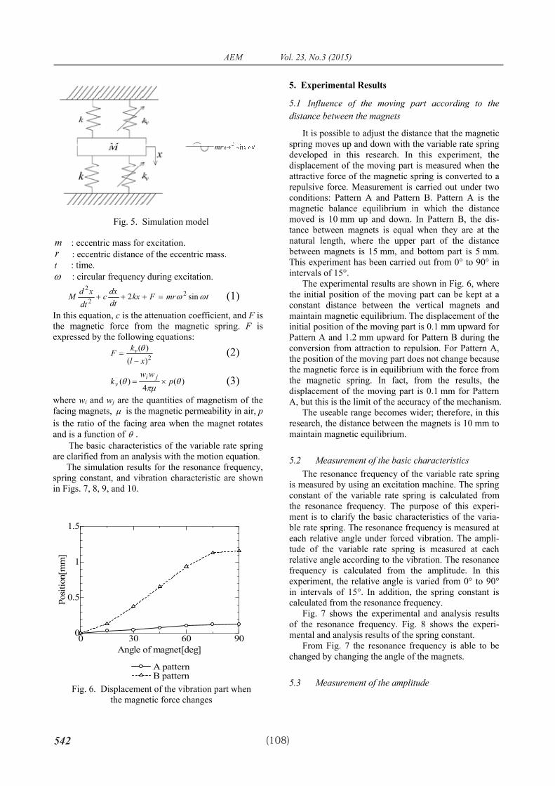
Fig. 4 shows the measurement of the magnetic flux density with the flux concentration method. The maxi-mum magnetic flux density is measured at the top surface, which is the side where the magnets face each other. This is twice as high as the magnetic flux at the bottom surface of the magnet.
4. Simulation
The equation of motion is shown in (1). Construc-tion of the variable rate spring is based on an actual experimental device that is then simulated. The simula-tion model of the variable rate spring is shown in Fig. 5 The amplitude of moving part is x, and the initial distance of the magnets is l. The parameters are as follows: k : spring constant of the compression spring. vk : coefficient of the magnetic spring. l : initial distance of the magnets. M : mass of the vibration part.
Fig. 3. Model of the flux concentration method
� Outside magnet � Flux concentration part � Bottom magnet � Inside magnet
Fig. 2. Model of the variable rate spring.
� Fixed magnet � Rotation magnet � Compression spring � Linear guide � Moving part
Fig. 4. Measurement of magnetic flux�
542
日本 AEM 学会誌 Vol. 23, No.3 (2015)
(108)
m : eccentric mass for excitation. r : eccentric distance of the eccentric mass. t : time. � : circular frequency during excitation.
tmrFkxdtdxc
dtxdM �� sin2 22
2���� (1)
In this equation, c is the attenuation coefficient, and F is the magnetic force from the magnetic spring. F is expressed by the following equations:
2)()(
xlkF v
��
� (2)
)(4
)( ���
� pww
k jiv �� (3)
where wi and wj are the quantities of magnetism of the facing magnets, � is the magnetic permeability in air, pis the ratio of the facing area when the magnet rotates and is a function of � .
The basic characteristics of the variable rate spring are clarified from an analysis with the motion equation.
The simulation results for the resonance frequency, spring constant, and vibration characteristic are shown in Figs. 7, 8, 9, and 10.
5. Experimental Results
5.1 Influence of the moving part according to the distance between the magnets
It is possible to adjust the distance that the magnetic spring moves up and down with the variable rate spring developed in this research. In this experiment, the displacement of the moving part is measured when the attractive force of the magnetic spring is converted to a repulsive force. Measurement is carried out under two conditions: Pattern A and Pattern B. Pattern A is the magnetic balance equilibrium in which the distance moved is 10 mm up and down. In Pattern B, the dis-tance between magnets is equal when they are at the natural length, where the upper part of the distance between magnets is 15 mm, and bottom part is 5 mm. This experiment has been carried out from 0° to 90° in intervals of 15°.
The experimental results are shown in Fig. 6, where the initial position of the moving part can be kept at a constant distance between the vertical magnets and maintain magnetic equilibrium. The displacement of the initial position of the moving part is 0.1 mm upward for Pattern A and 1.2 mm upward for Pattern B during the conversion from attraction to repulsion. For Pattern A, the position of the moving part does not change because the magnetic force is in equilibrium with the force from the magnetic spring. In fact, from the results, the displacement of the moving part is 0.1 mm for Pattern A, but this is the limit of the accuracy of the mechanism.
The useable range becomes wider; therefore, in this research, the distance between the magnets is 10 mm to maintain magnetic equilibrium.
5.2 Measurement of the basic characteristics The resonance frequency of the variable rate spring
is measured by using an excitation machine. The spring constant of the variable rate spring is calculated from the resonance frequency. The purpose of this experi-ment is to clarify the basic characteristics of the varia-ble rate spring. The resonance frequency is measured at each relative angle under forced vibration. The ampli-tude of the variable rate spring is measured at each relative angle according to the vibration. The resonance frequency is calculated from the amplitude. In this experiment, the relative angle is varied from 0° to 90° in intervals of 15°. In addition, the spring constant is calculated from the resonance frequency.
Fig. 7 shows the experimental and analysis results of the resonance frequency. Fig. 8 shows the experi-mental and analysis results of the spring constant.
From Fig. 7 the resonance frequency is able to be changed by changing the angle of the magnets.
5.3 Measurement of the amplitude
Fig. 5. Simulation model
0 30 60 900
0.5
1
1.5
Angle of magnet[deg]
Posi
tion[
mm
]
A pattern B pattern
Fig. 6. Displacement of the vibration part when the magnetic force changes
日本 AEM 学会誌 Vol. 23, No.3 (2015)
543(109)
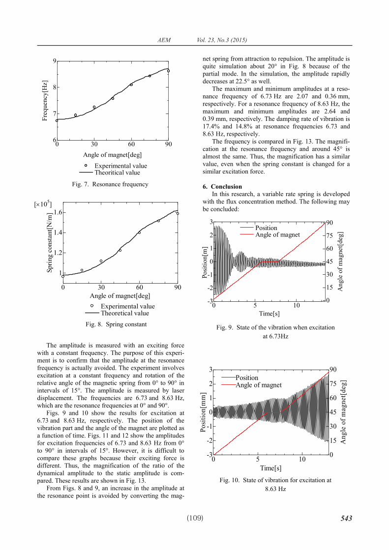
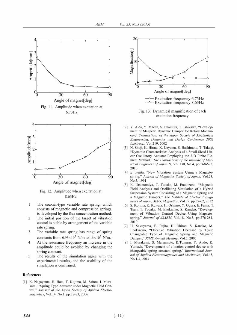
The amplitude is measured with an exciting force with a constant frequency. The purpose of this experi-ment is to confirm that the amplitude at the resonance frequency is actually avoided. The experiment involves excitation at a constant frequency and rotation of the relative angle of the magnetic spring from 0° to 90° in intervals of 15°. The amplitude is measured by laser displacement. The frequencies are 6.73 and 8.63 Hz, which are the resonance frequencies at 0° and 90°.
Figs. 9 and 10 show the results for excitation at 6.73 and 8.63 Hz, respectively. The position of the vibration part and the angle of the magnet are plotted as a function of time. Figs. 11 and 12 show the amplitudes for excitation frequencies of 6.73 and 8.63 Hz from 0° to 90° in intervals of 15°. However, it is difficult to compare these graphs because their exciting force is different. Thus, the magnification of the ratio of the dynamical amplitude to the static amplitude is com-pared. These results are shown in Fig. 13.
From Figs. 8 and 9, an increase in the amplitude at the resonance point is avoided by converting the mag-
net spring from attraction to repulsion. The amplitude is quite simulation about 20° in Fig. 8 because of the partial mode. In the simulation, the amplitude rapidly decreases at 22.5° as well.
The maximum and minimum amplitudes at a reso-nance frequency of 6.73 Hz are 2.07 and 0.36 mm, respectively. For a resonance frequency of 8.63 Hz, the maximum and minimum amplitudes are 2.64 and 0.39 mm, respectively. The damping rate of vibration is 17.4% and 14.8% at resonance frequencies 6.73 and 8.63 Hz, respectively.
The frequency is compared in Fig. 13. The magnifi-cation at the resonance frequency and around 45° is almost the same. Thus, the magnification has a similar value, even when the spring constant is changed for a similar excitation force.
6. Conclusion In this research, a variable rate spring is developed
with the flux concentration method. The following may be concluded:
Fig. 8. Spring constant
0 30 60 90
1
1.2
1.4
1.6[�105]
Angle of magnet[deg]
Sprin
g co
nsta
nt[N
/m]
Experimental value Theoretical value
0 5 10-3
-2
-1
0
1
2
3
0
15
30
45
60
75
90
Time[s]
Posi
tion[
m]
Position Angle of magnet
Ang
le o
f mag
net[d
eg]
Fig. 9. State of the vibration when excitation at 6.73Hz
Fig. 10. State of vibration for excitation at 8.63 Hz
0 5 10-3
-2
-1
0
1
2
3
0
15
30
45
60
75
90
Time[s]
Posi
tion[
mm
]
Ang
le o
f mag
net[d
eg]Position
Angle of magnet
Fig. 7. Resonance frequency
0 30 60 906
7
8
9
Angle of magnet[deg]
Freq
uenc
y[H
z]
Experimental value Theoritical value
544
日本 AEM 学会誌 Vol. 23, No.3 (2015)
(110)
1 The coaxial-type variable rate spring, which consists of magnetic and compression springs, is developed by the flux concentration method.
2 The initial position of the target of vibration control is stable by arrangement of the variable rate spring.
3 The variable rate spring has range of spring constants from 51095.0 � N/m to 5106.1 � N/m.
4 At the resonance frequency an increase in the amplitude could be avoided by changing the spring constant.
5 The results of the simulation agree with the experimental results, and the usability of the simulation is confirmed.
References
[1] K. Nagayama, H. Hata, T. Kojima, M. Saitou, I. Mura-kami, “Spring Type Actuator under Magnetic Field Con-trol,” Journal of the Japan Society of Applied Electro-magnetics, Vol.14, No.1, pp.78-83, 2006
[2] Y. Aida, Y. Maeda, S. Imamura, T. Ishikawa, “Develop-ment of Magnetic Dynamic Damper for Rotary Machin-ery,” Transactions of the Japan Society of Mechanical Engineering, Dynamics and Design Conference 2002(abstract), Vol.219, 2002
[3] N. Shoji, K. Hirata, K. Ueyama, E. Hashimoto, T. Takagi, “Dynamic Characteristics Analysis of a Small-Sized Lin-ear Oscillatory Actuator Employing the 3-D Finite Ele-ment Method,” The Transactions of the Institute of Elec-trical Engineers of Japan D, Vol.130, No.4, pp.568-573, 2010
[4] E. Fujita, “New Vibration System Using a Magneto-spring,” Journal of Magnetics Society of Japan, Vol.23, No.3, 1991
[5] K. Utsunomiya, T. Todaka, M. Enokizono, “Magnetic Field Analysis and Oscillating Simulation of a Hybrid Suspension System Consisting of a Magnetic Spring and a Magnetic Damper,” The Institute of Electrical Engi-neers of Japan, MAG, Magnetics, Vol.37, pp.57-62, 2012
[6] S. Kojima, K. Kuwata, H. Oshimo, Y. Ogura, E. Fujita, T. Tsuji, T. Todaka, M. Enokizino, S. Kaneko, “Develop-ment of Vibration Control Device Using Magneto-spring,” Journal of JSAEM, Vol.18, No.3, pp.276-281, 2010
[7] H. Sakuyama, E. Fujita, H. Ohimo, S. Kaneko, M. Enokizono, “Effective Vibration Decrease by Cycle Changeable Type of Magnetic Spring and Magnetic Damper,” JSME Annual Meeting, Vol.7, 2005
[8] I. Murakami, S. Matsumoto, K.Tomaru, Y. Ando, K. Yamada, “Development of vibration control device with changeable spring constant spring,” International Jour-nal of Applied Electromagnetics and Mechanics, Vol.45, No.1-4, 2014
Fig. 11. Amplitude when excitation at 6.73Hz
0 30 60 900
1
2
3
4
Angle of magnet[deg]
Am
pritu
de[m
m]
Fig. 12. Amplitude when excitation at 8.63Hz
0 30 60 900
1
2
3
4
Angle of magnet[deg]
Am
plitu
de[m
m]
Fig. 13. Dynamical magnification of each excitation frequency
0 30 60 900
10
20
Angle of magnet[deg]
Mag
nific
atio
n[-]
Excitation frequency 6.73Hz Excitation frequency 8.63Hz